Embed Size (px)
Citation preview
Constant-filled fluid coupling with valve control – Types TV…F…
2
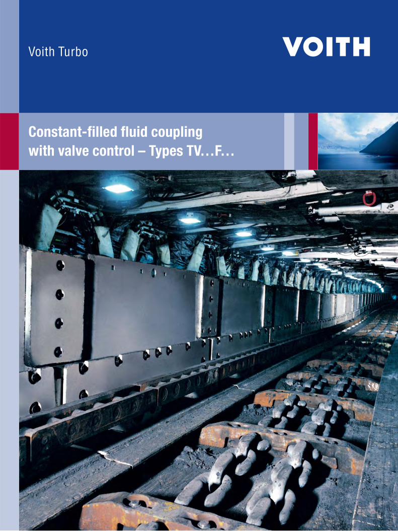
Voith Turbo fluid couplings with valve control:Putting traction on the chainBecause of the harsh operating conditions underground, AFC drives need to be extremely
robust and reliable. For this reason, high break down torque squirrel cage motors are nor-
mally chosen for this severe duty. These motors often have torque-speed curves which,
when combined with voltage drops, can intersect the AFC load curve (pull-up torque point)
creating a condition which will not produce sufficient torque to start a loaded conveyor.
To break away, a loaded or overloaded conveyor frequently requires the torque to be higher
than the nominal torque. This means that a direct connected (motor to gearbox) AFC drive
will have limited ability to start a loaded AFC. Also voltage drops cannot be excluded in
underground power supply systems and these reduce the motor‘s torque characteristic
and deteriorate the startup behavior. Voith fluid couplings with integral valve function
compensate for these negative influences and enable the motor and the conveyor to be
started up reliably.
Voith fluid couplings with speed-dependent valve control have proven their advantages in mining applications over several decades:
They work reliably in AFC and stage loader drives
1 Delay chamber2 Nozzle screw3 Centrifugal force valve4 Valve support5 Pump wheel6 Working circuit7 Turbine wheel8 Annular chamber
1
2
3
4
5
6
7
8
3D model, TVVFS coupling TWVF coupling in lantern (tunnel) housing
3
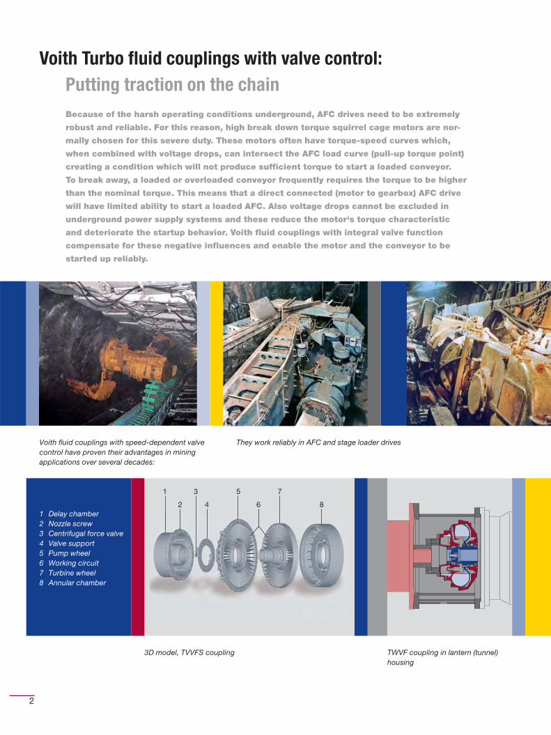
The Voith drive concept
The hydrodynamic and design properties of fluid couplings with
valve control are optimized for the conditions of use on AFCs
and stage loaders. In conjunction with squirrel cage motors,
they make up a robust drive system that is extremely reliable
and protects all drive components, particularly the chain.
Features of fl uid couplings
with valve control (types TVF, TVVF, TVVFS)
Advantages
Hydrodynamics Hydrodynamic power transmission based on the
Föttinger principle. A rotating fl uid fl ow creates
the torque transmission between the input and
output runners.
n Power transmission with almost zero wearn Load-free motor run-upn Smooth build-up of starting torquen Dampening of torsional vibrations and impacts on the drive chainn Automatic load sharing in multi-motor drivesn Robust and reliable drive concept with squirrel cage motorsn Protection of all drive components, particularly the chainn High effi ciency
Valve control Centrifugal valves control the filling and draining
of the working circuit volume as a function of
motor speed, thereby influencing the torque
transmission behavior of the coupling.
n Relieves load on drive motor in case of voltage drops resulting in
motor speeds below the break down torque pointn Utilization of motor break down torque after run-upn No external control and regulating equipment necessary
Design Compact and simple design n Small space requiredn Servicing easy to carry out
Depending on the coupling type, large chambers
for the operating fl uid with corresponding
additional heat capacity.
n High startup frequencyn Startup against high breakaway torques
Components with symmetrical rotation n Clockwise and counter clockwise rotation with identical
properties
Operating fl uid Versions available for oil, water and HFD fl uids n Environmentally friendlyn Complies with offi cial requirementsn Available in trade outlets worldwide
Approvals Mining approvals obtained for a variety of
countries
n Certifi ed drive components complying with local mining
regulations
4
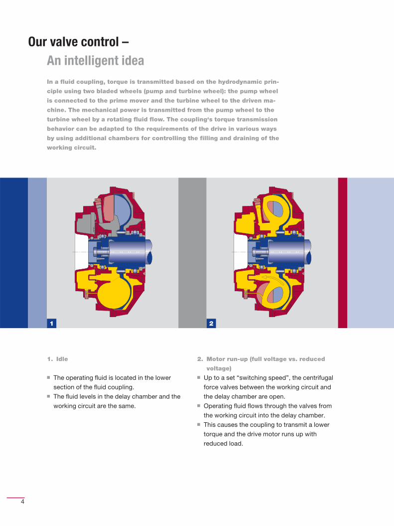
Our valve control – An intelligent ideaIn a fluid coupling, torque is transmitted based on the hydrodynamic prin-
ciple using two bladed wheels (pump and turbine wheel): the pump wheel
is connected to the prime mover and the turbine wheel to the driven ma-
chine. The mechanical power is transmitted from the pump wheel to the
turbine wheel by a rotating fluid flow. The coupling‘s torque transmission
behavior can be adapted to the requirements of the drive in various ways
by using additional chambers for controlling the filling and draining of the
working circuit.
1. Idle
n The operating fl uid is located in the lower
section of the fl uid coupling.n The fl uid levels in the delay chamber and the
working circuit are the same.
2. Motor run-up (full voltage vs. reduced
voltage)n Up to a set “switching speed”, the centrifugal
force valves between the working circuit and
the delay chamber are open.n Operating fl uid fl ows through the valves from
the working circuit into the delay chamber.n This causes the coupling to transmit a lower
torque and the drive motor runs up with
reduced load.
1 2
5
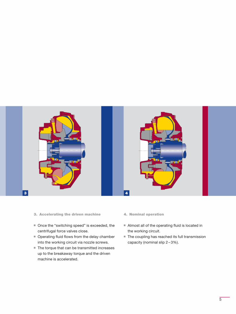
3. Accelerating the driven machine
n Once the “switching speed” is exceeded, the
centrifugal force valves close.n Operating fl uid fl ows from the delay chamber
into the working circuit via nozzle screws.n The torque that can be transmitted increases
up to the breakaway torque and the driven
machine is accelerated.
4. Nominal operation
n Almost all of the operating fl uid is located in
the working circuit.n The coupling has reached its full transmission
capacity (nominal slip 2 – 3%).
3 4
6
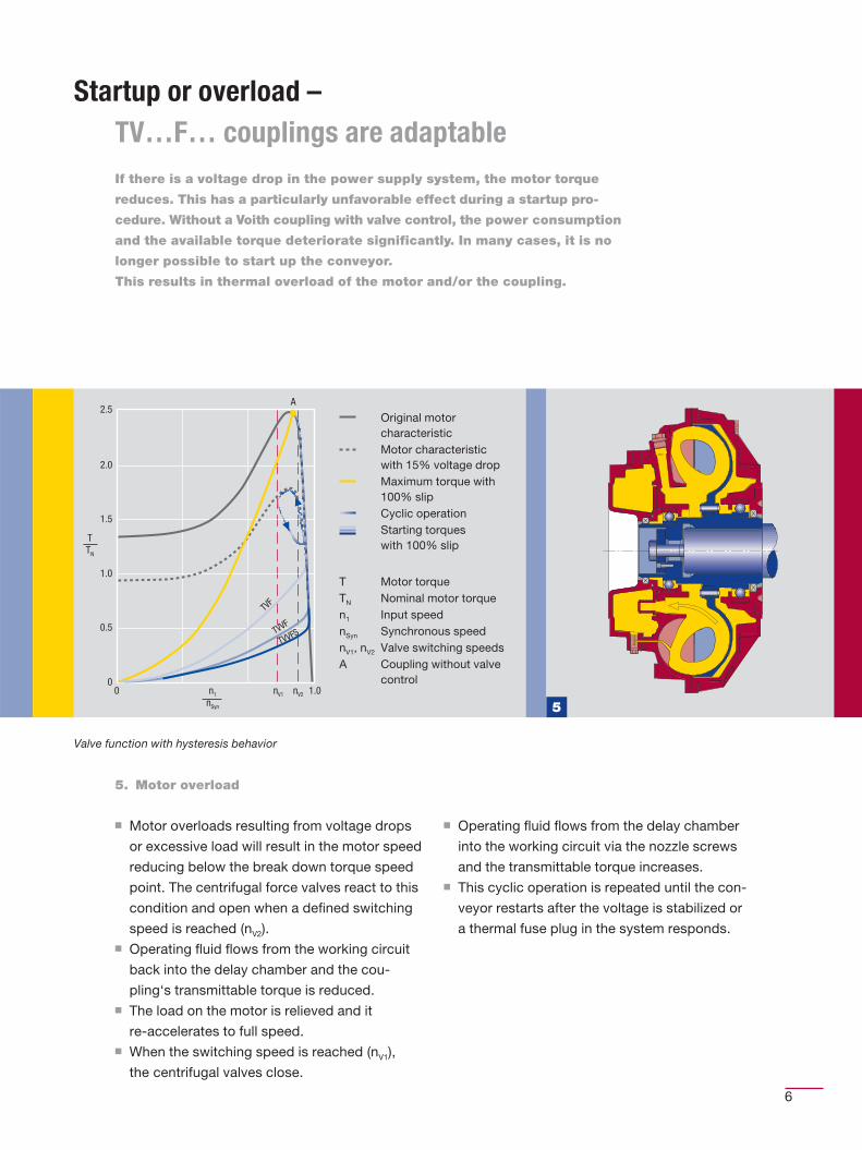
5. Motor overload
n Motor overloads resulting from voltage drops
or excessive load will result in the motor speed
reducing below the break down torque speed
point. The centrifugal force valves react to this
condition and open when a defi ned switching
speed is reached (nV2).n Operating fl uid fl ows from the working circuit
back into the delay chamber and the cou-
pling‘s transmittable torque is reduced.n The load on the motor is relieved and it
re-accelerates to full speed.n When the switching speed is reached (nV1),
the centrifugal valves close.
n Operating fl uid fl ows from the delay chamber
into the working circuit via the nozzle screws
and the transmittable torque increases.n This cyclic operation is repeated until the con-
veyor restarts after the voltage is stabilized or
a thermal fuse plug in the system responds.
Startup or overload –TV…F… couplings are adaptableIf there is a voltage drop in the power supply system, the motor torque
reduces. This has a particularly unfavorable effect during a startup pro-
cedure. Without a Voith coupling with valve control, the power consumption
and the available torque deteriorate significantly. In many cases, it is no
longer possible to start up the conveyor.
This results in thermal overload of the motor and/or the coupling.
Valve function with hysteresis behavior
2.5
2.0
1.5
1.0
0.5
00 1.0n1
nSyn
nV1 nV2
TTN
A
TVVFSTVVF
TVF
5
Original motor characteristicMotor characteristic with 15% voltage dropMaximum torque with 100% slipCyclic operationStarting torques with 100% slip
T Motor torqueTN Nominal motor torquen1 Input speednSyn Synchronous speednV1, nV2 Valve switching speedsA Coupling without valve
control
7
The right coupling for every driveThe critical factors in the design of a fluid coupling are the power and speed
of the drive motor. Other factors include startup frequency, maximum trans-
mittable torque and the time-dependent build-up of the starting torque.
When it comes to choosing the most suitable fluid coupling for your drive,
you can rely on our sales engineers‘ decades of experience. We will be happy
to advise you.
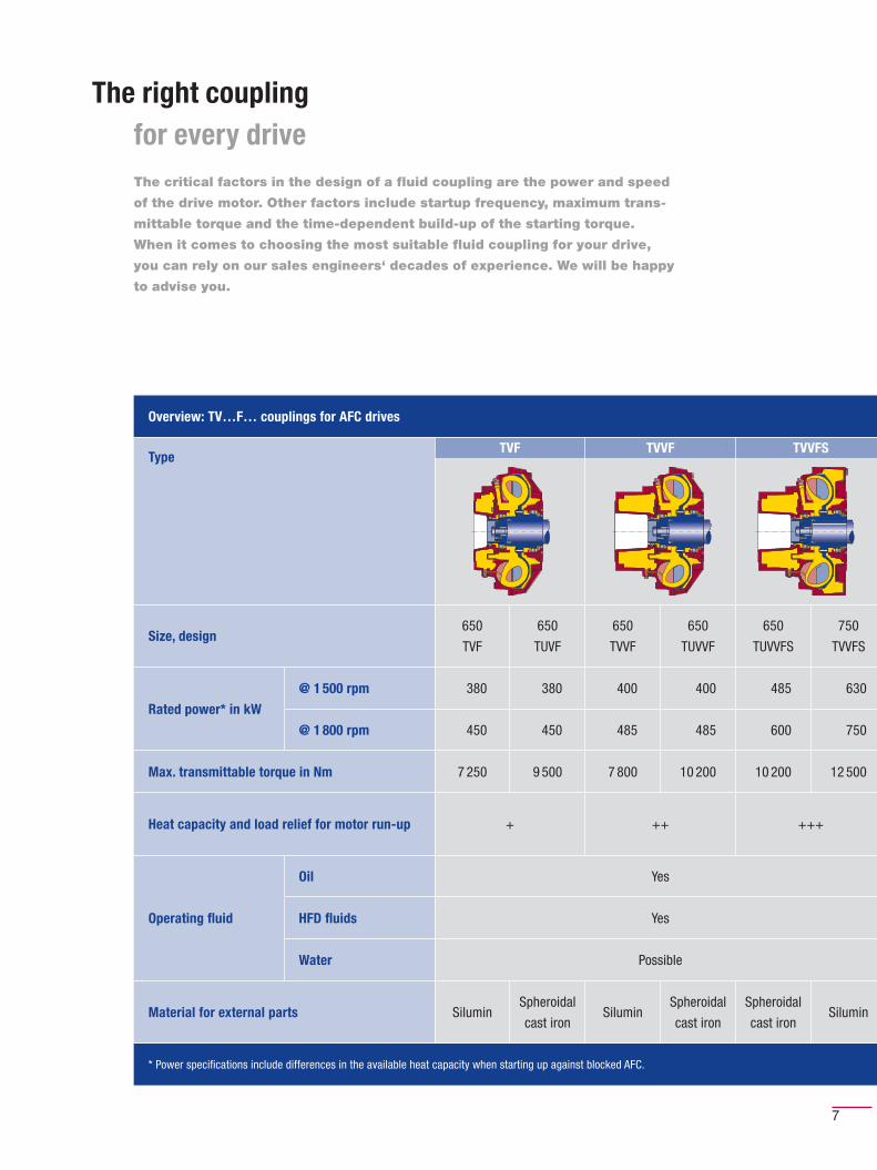
Overview: TV…F… couplings for AFC drives
TypeTVF TVVF TVVFS
Size, design650
TVF
650
TUVF
650
TVVF
650
TUVVF
650
TUVVFS
750
TVVFS
Rated power* in kW
@ 1 500 rpm 380 380 400 400 485 630
@ 1 800 rpm 450 450 485 485 600 750
Max. transmittable torque in Nm 7 250 9 500 7 800 10 200 10 200 12 500
Heat capacity and load relief for motor run-up + ++ +++
Operating fl uid
Oil Yes
HFD fl uids Yes
Water Possible
Material for external parts SiluminSpheroidal
cast ironSilumin
Spheroidal
cast iron
Spheroidal
cast ironSilumin
* Power specifi cations include differences in the available heat capacity when starting up against blocked AFC.
8
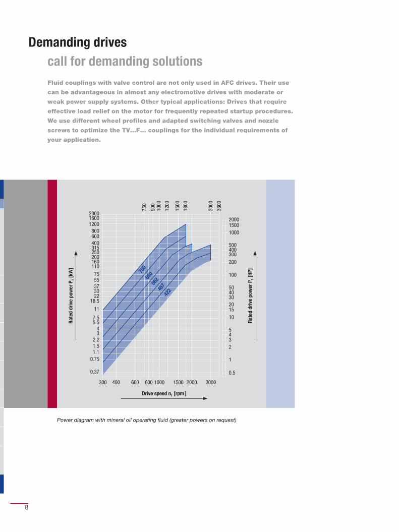
Demanding drives call for demanding solutionsFluid couplings with valve control are not only used in AFC drives. Their use
can be advantageous in almost any electromotive drives with moderate or
weak power supply systems. Other typical applications: Drives that require
effective load relief on the motor for frequently repeated startup procedures.
We use different wheel profiles and adapted switching valves and nozzle
screws to optimize the TV…F… couplings for the individual requirements of
your application.
Power diagram with mineral oil operating fluid (greater powers on request)
200016001200800600400315250200160110
7555373022
18.5
11
7.55.5
43
2.21.51.1
0.75
0.37
300 400 600 800 1000 1500 2000 3000
200015001000
500400300200
100
504030201510
5432
1
0.5
750
900
1000
1200
1500
1800
3000
3600
750
650
562
487
422
Rate
d dr
ive
pow
er P
1 [kW
]
Rate
d dr
ive
pow
er P
1 [HP
]
Drive speed n1 [rpm ]
9
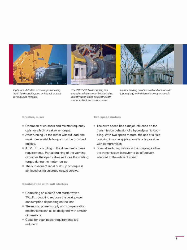
Optimum utilization of motor power using Voith fluid couplings on an impact crusher for reducing minerals.
The 750 TVVF fluid coupling in a strander, which cannot be started up directly when using an electric soft starter to limit the motor current.
Harbor loading plant for coal and ore in Vado Ligure (Italy) with different conveyor speeds.
Crusher, mixer
n Operation of crushers and mixers frequently
calls for a high breakaway torque.n After running up the motor without load, the
maximum available torque must be provided
quickly.n A TV…F… coupling in the drive meets these
requirements. Partial draining of the working
circuit via the open valves reduces the starting
torque during the motor run-up.n The subsequent rapid build-up of torque is
achieved using enlarged nozzle screws.
Combination with soft starters
n Combining an electric soft starter with a
TV…F… coupling reduces the peak power
consumption depending on the load.n The motor, power supply and compensation
mechanisms can all be designed with smaller
dimensions.n Costs for peak power requirements are
reduced.
Two speed motors
n The drive speed has a major infl uence on the
transmission behavior of a hydrodynamic cou-
pling. With two speed motors, the use of a fl uid
coupling in some applications is only possible
with compromises.n Special switching valves in the couplings allow
the transmission behavior to be effectively
adapted to the relevant speed.
Voith Turbo GmbH & Co. KG
Start-up Components
Voithstr. 1
74564 Crailsheim, Germany
Tel. +49 7951 32-409
Fax +49 7951 32-480
www.voithturbo.com/startup-components
cr 1
36 e
n, a
ik-S
DL
/ WA
, 05.
2007
, 150
0. D
imen
sio
ns a
nd il
lust
ratio
ns w
itho
ut o
blig
atio
n. S
ubje
ct t
o m
od
ifica
tions
.


![[Kutak, K.; Surówka, P.] Non-linear Evolution of Unintegrated Gluon Density at Large Values of Coupling Constant](https://img.pdfslide.us/doc/110x75/5695d42a1a28ab9b02a085ae/kutak-k-surowka-p-non-linear-evolution-of-unintegrated-gluon-density.jpg)