Embed Size (px)
Citation preview
. CONSTANT-CU NT CHARGING SUPPLIES FOR THE ADVANCED
PHOTON SOURCE (APS) LINEAR ACCELERATOR MODULATORS
R. Fuja, A. E. Grelick, D. LMeyer, G. Pile, andiM. White Advanced Photon Source, Argonne National Laboratory,
9700 South Cass Avenue, Argonne. Illinois 60439-4800 USA
Abstract The APS [1,2] linac beam energy must be stable to
within 21% to match the energy acceptance of the positron accumulator ring. The klystron pulse modulators [3,4] must therefore provide a pulse-to-pulse repeatability of 0.1% in order for the beam to have the required energy stability. The modulators have had difficulty achieving the necessary repeatability since the pulse forming network (PFN) charging scheme does not include a deQing circuit. Several of the major charging circuit components are also less reliable than desired. In order to increase operating reliability and to improve pulse-to-pulse stability, it is planned to replace the high voltage power supplies in all modulators with constant- current power supplies. A new modulator charging supply that contains two EM1 [SI series 303 constant-current power supplies was constructed. Each of these EM1 supplies delivers 1.5 A at up to 40 kV. One supply is sufficient for linac operation at up to 15 Hz, and two supplies in parallel enable linac operation at the nominal rf repetition rate of 60 Hz. This paper discusses test results from the new modulator, and ais0 describes the existing modulators and their performance limitations.
1 INTRODUCTION In the five existing APS linac modulators, a 12-pulse
unregulated power supply and a 22-Henry inductor are used to resonantly charge a 0.7W-pF P F 3 capacitance to the desired voltage through a tetrode switch tube. When the switch opens, energy in the charging inductor increases the PFN voltage to a higher value. This new PFN voltage level can vary from pulse to pulse depending on the voltage level of the charging supply. The charging supply's output voltage is affected by the rather frequent AC line voltage fluctuations. The 60-Hz. 20-kV charging supply. the tetrode switch tube. the 22-Henry charging inductor. and other ancillary cquipment require control and protection circuitry and also a fair amount of space.
The heat generated by the 100-A tetrode filament current must also be dealt with. Use of a series tetrode as the charge-controlling element is not ideal, because screen grid current can become excessive as the plate voltage drops to a value near the screen -grid voltage.
The P J 3 is normally charged to 33 kV, and for f 0.18 regulation. a c 33-V variation can be tolerated. Use of a '?-Henry charging inductor means that the current in the inductor is required to remain to within 2 5 mA at the
3UH 0 9 $ 1
time the tetrode opens. This is impossibIe in this non- deQed configuration because of the large stored e n e r g in the inductor.
.4C line variations of 3% can easily be seen during normal running, and power line variations of 5% can happen at certain times of the day.
In order to overcome the limitations of the present configuration, a sixth modulator and klystron system, eventually intended as an on-line spare, was fitted with two EM1 series 303 constant-current charging supplies. These supplies are rated at 40 kV and 1.5 A, and are capable of an average power output of 30kW. In the next section, we compare regulation of the new modulator with constant-current supplies to regulation of our standard modulators with resonant-charging systems.
2 TESTRESULTS Power supply regulation data were obtained for both
types of charging systems while the 1000-A, 2-Hz pulsed, booster synchrotron power supplies were off and also while they were on. The modulator PFN set point voltage, the actual measured modulator PFN voltage, and the incoming AC line voltage were logged and analyzed using software from the SDDS toolkit [6]. Power supply regulation data for the two types of charsing systems were captured using the built-in envelope detector on an HP 54542 A oscilloscope.
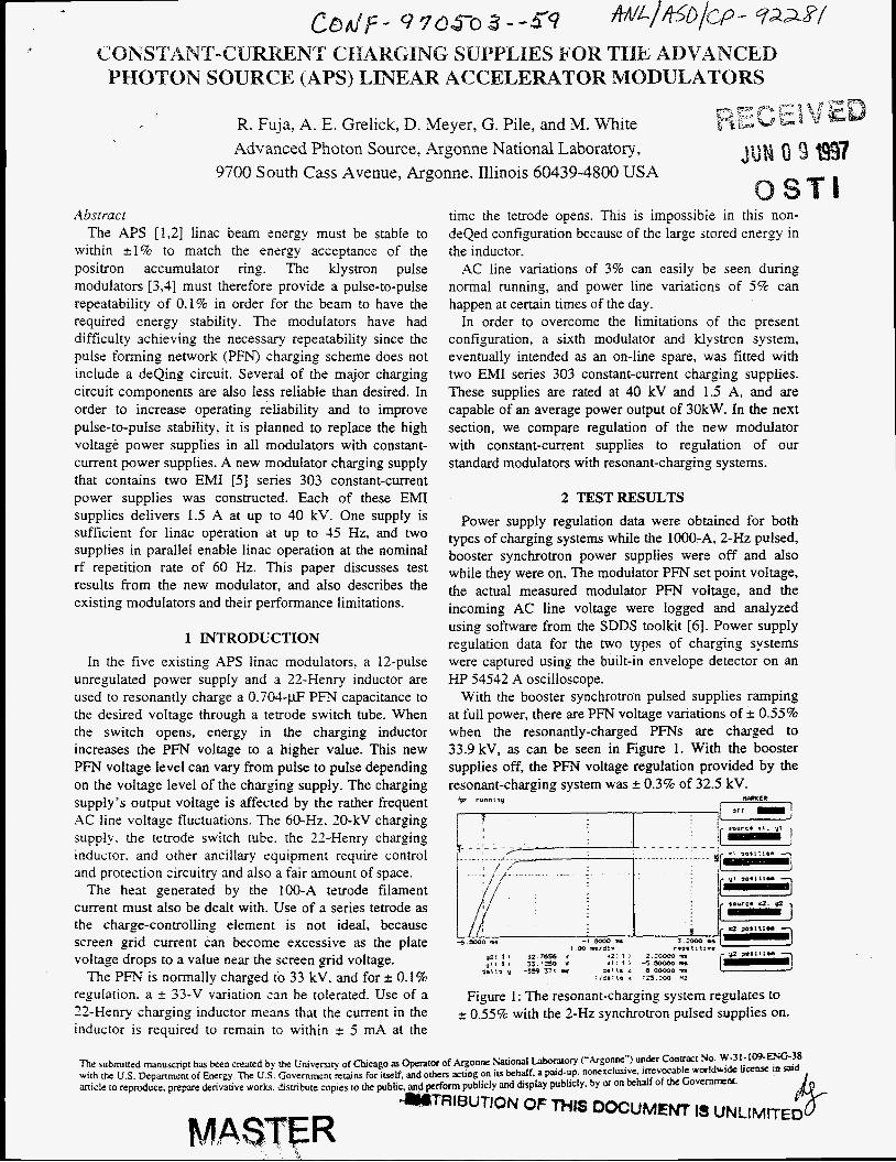
With the booster synchrotron pulsed supplies ramping at full power, there are PFN voltage variations of 2 0.55% when the resonantly-charged PFNs are charged to 33.9 kV, as can be seen in Figure 1. With the booster supplies off, the PFN voltage regulation provided by the resonant-charging system was 0.3% of 32.5 kV.
1-j i ; hm- 1
fp running
I ? SOYTC. X I . ) t
Figure 1: The resonant-charging system regulates to ~t: 0.55% with the 2-Hz synchrotron pulsed supplies on.

Portions of this document m y be iilegible in elecaoaic image products are prpduced from the best availabie original document.
DISCLAIMER
This report was prepared as an account of work sponsored by an agency of the United States Government. Neither the United States Government nor any agency thereof, nor any of their employees, makes any warranty, express or implied, or assumes any legal liability or responsibility for the accuracy, completeness, or use- fulness of any information, apparatus, product, or process disclosed, or represents that its use would not infringe privately owned rights. Reference herein to any spe- cific commercial product, process, or service by trade name, trademark, manufac- turer, or otherwise dots not necessarily constitute or imply its endorsement, recorn- mendktion, or favoring by the United States Government or any agency thereof. The views and opinions of authors expressed herein do not necessarily state or reflect those of the United States Government or any agency thereof.
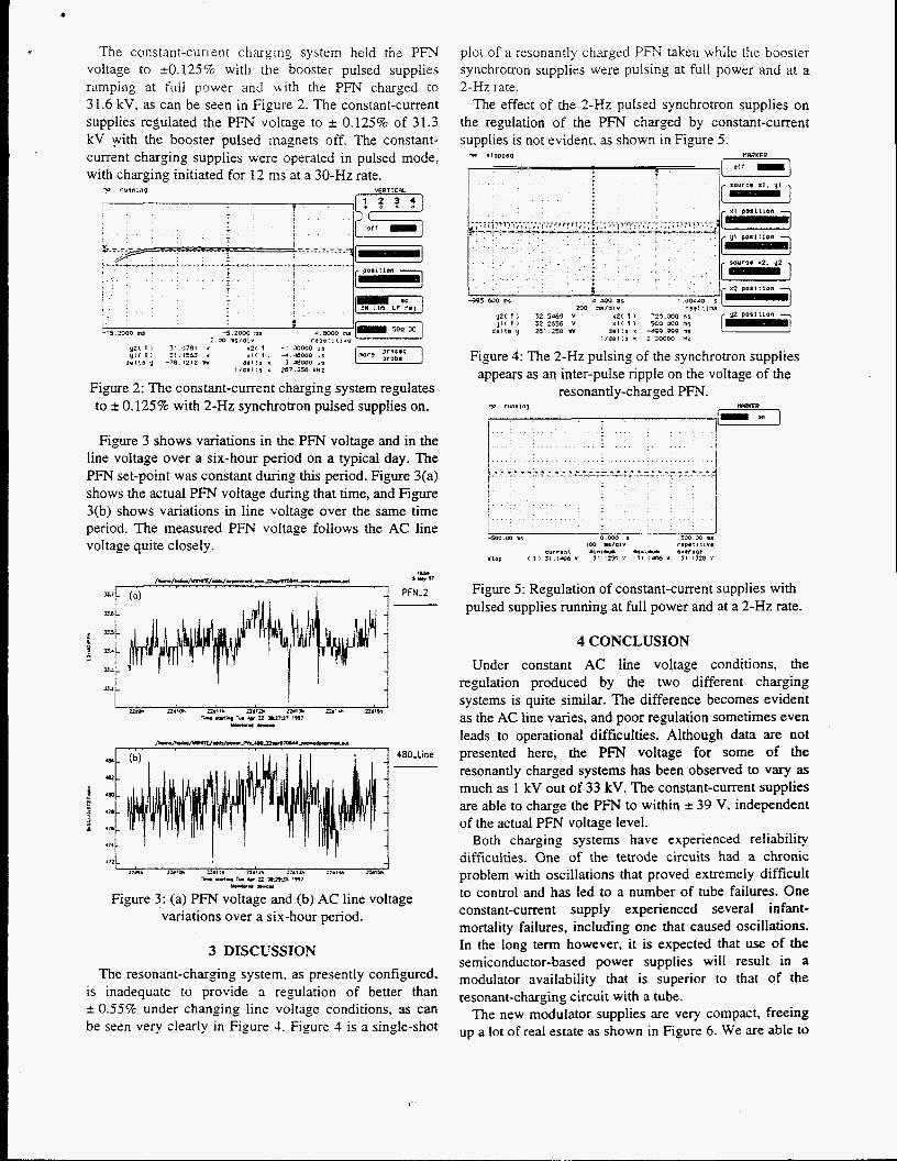
i The constant-current charging system held the Y F N voltage to +.O. 125% with the booster pulsed supplies ramping at full pQwer and with the PFN charged to 3 1.6 kV, as can be seen in Figure 2. The constant-current supplies regulated the PFN voltage to 2 0.125% of 31.3 kV with'the booster pulsed magnets off. The constant- current charging supplies were operated in pulsed mode, with charging initiated for 12 ms at a 30-Hz rate.
"P runo1ng VERTICRL
j . .
-15.2000 I S -5.iooo zu i 30 l I S l 4 , " 1-1 y2( l ! 3!.9781 1 x2c 1 - I 1)oooo ,,
y I ( 1 ) 31.1563 V X i ( 1 : 4 . ~ 0 0 0 .P asita 'I - 7 8 . 1 2 1 ~ w a l l l a * 3.UIM)o 2,
1/4@ita < 297.556 kHL
Figure 2: The constant-current charging system regulates to t 0.125% with 2-Hz synchrotron pulsed supplies on.
Figure 3 shows variations in the PFN voltage and in the line voltage over a six-hour period on a typical day. The PFN set-point was constant during this period. Figure 3(a) shows the actual PFN voltage during that time, and Figure 3(b) shows variations in line voltage over the same time period. The measured PFN voltage follows the AC line voltage quite closely.
I
nbu 12.1- n a t m n a u . i i a m zw.. ne?% rrr .inl I n -2 '-7
YlUL-
Figure 3: (a) PFN voltage and (b) AC line voltage variations over a six-hour period.
3 DISCUSSION The resonant-charsing system, as presently configured.
is inadequate to provide a regulation of better than t 0.55% under changing line voltage conditions, as can be seen very clearly in Figure 1. Figure 1 is a single-shot
plot of a resonantly charged PFN taken while the booster synchrotron supplies were pulsing at full power and at a 2-Hz rate.
The effect of the 2-Hz pulsed synchrotron supplies on the regulation of the PFN charged by constant-current supplies is not evident. as shown in Figure 5. 4 SIOPPBI
Figure 4: The 2-Hz pulsing of the synchrotron supplies appears as an inter-pulse ripple on the voltage of the
resonantly-charged PFN. *p running
1- I I
1 I
Figure 5: Regulation of constant-current supplies with pulsed supplies running at full power and at a 2-Hz rate.
4 CONCLUSION Under constant AC line voltage conditions, the
regulation produced by the two different charging systems is quite similar. The difference becomes evident as the AC line varies, and poor regulation sometimes even leads to operational difficulties. Although data are not presented here, the PFN voltage for some of the resonantly charged systems has been observed to vary as much as 1 kV out of 33 kV. The constant-current supplies are able to charge the PFN to within -c 39 V, independent of the actual PFN voltage level.
Both charging systems have experienced reliability difficuities. One of the tetrode circuits had a chronic problem with oscillations that proved extremely difficult to control and has led to a number of tube failures. One constant-current supply experienced several infant- mortality failures, including one that caused oscillations. In the long term however, it is expected that use of the semiconductor-based power supplies will result in a modulator availability that is superior to that of the resonant-charging circuit with a tube.
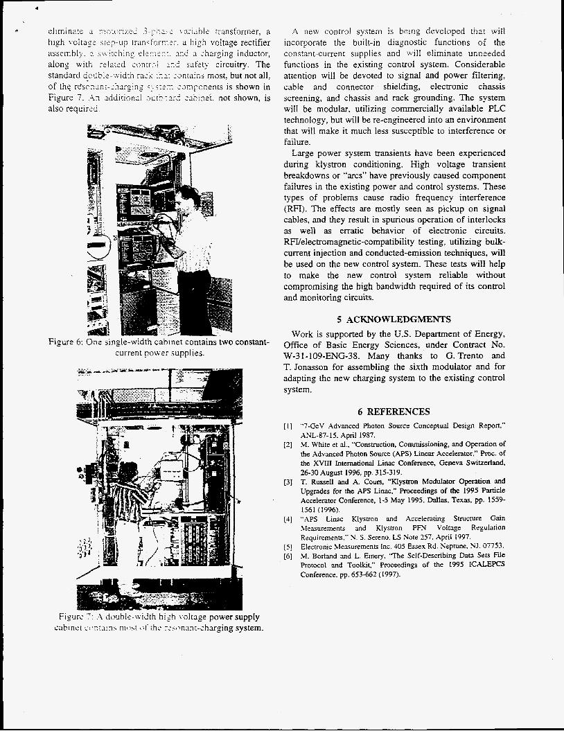
The new modulator supplies are very compact, freeing up a lot of real estate as shown in Figure 6. We are able to
1
A Lnri;i’e!e transformer, a rr.:r. a high voltage rectifier
assembly. 3 ,v%i-iLching el-rn-::. ?!id charging inductor, along with related a n m i ~ n d safety circuitry. The standard dc&Ie-xidth iuc‘ zzntains most, but not all,
,-=rnpcnsnts is shown in Figure 7. .i:i idditionui JECC?,:L-~ a b i n s ‘ t . not shown, is also required.
I-
C_
Figure 6: Ons single-width cabinet contains two constant- current power supplies.
A nebv control system is being developed triat will incorporate the built-in diagnostic functions of the constant-current supplies and will eliminate unneeded functions in the existing control system. Considerable attention will be devoted to signal and power filtering, cable and connector shielding, electronic chassis screening, and chassis and rack grounding. The system will be modular, utilizing commercially available PLC technology, but will be re-engineered into an environment that will make it much less susceptible to interference or failure.
Large power system transients have been experienced during klystron conditioning. High voltage transient breakdowns or “arcs” have previously caused component failures in the existing power and control systems. These types of problems cause radio frequency interference (RFI). The effects are mostly seen as pickup on signal cables, and they result in spurious operation of interlocks as well as erratic behavior of electronic circuits. Welectromagnetic-compatibility testing, utilizing bulk- current injection and conducted-emission techniques, will be used on the new control system. These tests wiII help to make the new control system reliable without compromising the high bandwidth required of its control and monitoring circuits.
5 ACKNOWLEDGMENTS Work is supported by the U.S. Department of Energy,
Office of Basic Energy Sciences, under Contract No. W-31-109-ENG-38. Many thanks to G. Trento and T. Jonasson for assembling the sixth modulator and for adapting the new charging system to the existing control system.
6 REFERENCES [I]
[2]
“7-GeV Advanced Photon Source Conceptual Design Report,” ANL-87-15, April 1987. M. Whte et al., “Construction, Commissioning, and Operation of the Advanced Photon Source (APS) Linear Accelerator.” Roc. of the XVIII International Linac Conference, Geneva Switzerland,
T. Russell and A. Cours, “Klystron Modulator Operation and Upgrades for the APS Linac,” Proceedings of the 1995 Particle Accelerator Conference, 1-5 May 1995, Dallas, Texas, pp. 1559- 1561 (1996).
[4] “APS Linac Klystron and Accelerating Suucture Gain hlesurements and Klystron P N Voltage Regutation Requirements:’ N. S. Sereno. LS Note 257, April 1997. Electronic Measurements Inc. 405 Essex Rd. Neptune. NJ. 07753. M. Bodand and L. Emery. “The Self-Describing Dam Sets File Protocol and Toolkit,” Proceedings of the 1995 ICALJZPCS Conference. pp. 653-662 (1997).
26-30 August 1996, pp. 315-319. [3]
[ j ] [6]