Embed Size (px)
Citation preview
CONSOLIDATION PRACTICES IN CONCRETE PAVEMENT CONSTRUCTION
by
W. B. Ledbetter
Associate Research Engineer
Texas Transportation Institute
Harvey Treybig
Associate Design Engineer
Texas Highway Department
Research Report 128-1 (Final)
Concrete Pavement Consolidation
Research Study 2-8-69-128
Sponsored by
the Texas Highway Department
in cooperation with
U.S. Department of Transportation
Federal Highway Administration
Bureau of Public Roads
August '1969
Texas Transportation Institute Texas A&M University College Station, Texas
i
Technical Reports Center Texas Transportation Institute

PREFACE
This report represents the findings from Type B research study 2-8-69-128 which was conducted at the Texas Transportation Institute in the cooperative research pro· gram with the Texas Highway Department and the U. S. Bureau of Public Roads.
The authors wish to acknowledge the guidance and assistance given by the many people contacted in connection with this study. In particular, special thanks are offered to Mr. T. E. Ziller of the Construction Division, Mr. Ray A. Vansickle and Mr. William V. Ward of the Houston Urban Office, Mr. R. W. Crook and Mr. H. D. Swilley of District 2, Mr. Frank Hebner and Mr. Lawrence Galfione of District 12, Mr. John A. Blasienz of District 17, Mr. John G. Keller and Mr. W. C. Gromatzky of District 18, Mr. Ken Nagai of District 20, and Mr. J. M. Battle of District 24.
In addition, the authors wish to acknowledge the assistance given them by the Fort Worth Division of the U. S. Corps of Engineers, and the Associated General Contractors Committee on Concrete Paving, Mr. Richard Turner, Chairman. They gave fully of their time in discussing their experiences with concrete consolidation.
The opinions, findings, and conclusions expressed in this publication are those of the authors and not necessarily those of the Bureau of Public Roads.
ii

ABSTRACT
The investigation involved an examination of current technology on concrete consolidation, current continuously reinforced concrete pavement (CRCP) consolidation praciices in Texas, and selected current concrete pavement problems through field examination and laboratory investigation. Principal conclusions reached were: (l) while the vast majority of concrete pavements are in excellent condition, inadequate concrete consolidation has been found in many areas of Texas, the most prevalent locations occurring adjacent to transverse construction joints in CRCP, (2) with proper construction control, rigorously enforced, these isolated consolidation problems can be minimized, (3) by introducing selected changes in current practices, consolidation problems can be minimized. Based on these conclusions, recommendations were made which involved the introduction of more effective construction controls and the introduction of selected changes in current practices.
iii

TABLE OF CONTENTS Page
PREFACE ____________________ ·····--··-·······---·-···················--··-·····-·-···-········------···-··------····-·····················································-·················· ii
ABSTRACT .................... ---·-··········-······-······--··-···-················-·----····························-··························-···············-···--··--······--··-······ iii
TABLE OF CONTENTS ........ ---·················--··········--················-······-·-····--------·-····-·····································--······-····-------------······ iv
LIST OF FIGURES ........ ---································································----·····································-·····--···-··-······················--·-··-···· v
LIST OF TABLES .................................... ·-················-·-···············-·-··-···································-···················-··--···-·························· vi
1. INTRODUCTION AND SUMMARY .................... ---·-···-····-·----------·--······--········································--·--···-··-··············-····-·- 1
1.1 Purpose .... ·-····················-······-----------------·-····················-··---···-···----····----·-····························-~---········-··--··-········-·········---· 1
1.2 Scope ............... ·-························-··-------------------······-····-·-···-··-············-··-·········-·········-·······················-·-··--·---·········-···--·-·-· l
1.3 Conclusions ..................................... ---·····--···········-···-··-······-·················-·····--··-·······-··················-···--····--·············-·······-·· 1
1.4 Recommendations .... ---···-······················-···········-·······--·-··---·-··-···--······-···-···································-·-·---------······················ 1
1.5 Implementation of Research Results .......................................... -----·-········-·--······-···························------····-·---·-·-········ l
2. PROBLEM AND APPROACH ... ·---···--····---··················-·-···········-··------·-····-·---·········---····-·················-···--····-···-···················· l
2.1 Current Technology ·-····················-·-·-···--·-···--·················------···--···-·······-·--······-·-·······-·······-··-······································ l
2.2 Survey of Pavement Consolidation Problems and Practices ....... ·-··················-·····-·--·------·····-····················-·······-· 2
2.3 Field Investigations of Concrete Pavement Problem Areas ............................... ----···------·-··-----···-······················· 3
2.4 Need for Statistical Control of Consolidation .......... -------······················-······--······-···············--···················--············· 6
3. SYNTHESIS OF PRESENT PRACTICES ................ ---····················-························-·-·················----·-············-···-··-·········- 7
4. APPENDIX .... ·---··································-··-··--······················-----------------···--·······--··--··-····-··-··--------··-··-········-·--······----·-·············· 8
4.1 Data ... ·--------····--···-··········----····---·---··-···········-··········--------------------··-·---··-···-······-···-···--·····-·-···········-·····------------················· 8
4.2 Example Special Provision Item 360 ..... ·-·····--·················---··--·-----------·············--··········-···········-···········--····-·-·-············13
4.3 References·--·--·-·····-·-··---·················-···········-···--·--·-------····--·····-·-··························--·········-············--··--···--·--··-·-·-------·--·····18
iv

LIST OF FIGURES Number Page
1 Concrete Area of Distress Adjacent to a Construction Joint in CRCP (core upside down to view honeycombing)------------------------------------------------------------------------------------------------------------- 2
2 Honeycombed Concrete Taken from the Bottom Side of Continuously Reinforced Concrete Pavement __________ 3
3 Comparison of Splitting Tensile Strength and Bulk Density Values for Area A_ _______________________________________________ 4
4 Comparison of Splitting Tensile Strength and Bulk Density Values for Area B_ _______________________________________________ 4
5 Comparison of Splitting Tensile Strength and Bulk Density Values for Area c_ _______________________________________________ 4
6 Core 4-1 From Area A-------------------------------------------------------------------------------------------------------------------------------------------------- 4
7 Core 5-1 From Area A-------------------------------------------------------------------------------------------------------------------------------------------------- 5
8 Core· 7-2 From Area A------------------------------------------------·------------------------------'------------------------------------------------------------------ 5
9 Core 3-3 From Area B------------------------------------------------·------------------------------------------------------------------------------------------------- 6
10 Core 2-2 From Area B-------------------------------------------------------------------------------------------------------------------------------------------------- 6
11 Comparison of Densities for the Top and Bottom of Concrete Cores from Good
and Poor Performing Areas (Area D)---------------------------------------------------------------------------------------------------------------------- 7
12 Comparison of the Tensile Strengths for Top and Bottom of Concrete Cores from
Good and Poor Performing Areas (Area D)-----······------------------------------------------------------------------------------------------------- 7
v

LIST OF TABLES Number Page
1 Data From Area A-------------------------------------------------------------------------------------------------------------------------------------------------------- 8
2 Statistical Analysis of Data From Area A.---------------------------------------------------------------------'------------------------------------------ 8
3 Data From Area B---------------------------------------------------------------------'---------------------------------------------------------------------------------- 9
4 Statistical Analysis of Data From Area R----------------------------------------------------------------------------------------------------------------- 9
5 Data From Area C-------------------------------------------------------------------------------------------------------------------------------------------------------- 9
6 Statistical Analysis of Data From Area c_ ___________________________________________________________________ ----------------------------------------------10
7 Data From Area D ______________________________________________________ -------------------------------------------------------------------------------------------------10
8 Statistical Analysis of Data From Area D ________________ -------------------------------------------------------------------------------------------------12
vi

1. Introduction and Summary
1.1 Purpose
The purpose of this study was to examine the current state-of-the-art in vibrating plastic paving concrete in Texas Highway Department construction and propose methods whereby the consolidation of the pavement might be improved.
1.2 Scope
The study involved three phases. They were (a) an examination of current technology in the field of concrete consolidation, (b) an examination of current continuously reinforced concrete pavement (CRCP) consolidation practices in the Texas Highway Department, and (c) an evaluation of selected current concrete pavement problems existing on Texas highways. These phases were performed concurrently and are reported herein.
1.3 Conclusions
l. Distress that appears to be attributed to inade• quate concrete consolidation has been found in many areas of Texas, the most prevalent locations occurring adjacent to transverse construction joints in CRCP.
2. With improved construction control, consolidation problems may be minimized.
3. By introducing selected changes in current construction practices, consolidation problems may be minimized.
1.4 Recommendations
l. Introduce more effective construction control over vibration of CRCP. This control could he accomplished by:
a. requiring a tachometer to measure vibration frequency at regular intervals on all projects,
b. utilizing concrete coring or some nondestructive technique to inspect consolidation in addition to thickness determinations,
c. making inspectors more aware of the potential problems in consolidation, especially adjacent to transverse construction joints, and,
d. requiring a visual indication on equipment to indicate whether or not internal vibrators are operating.
2. Introduce selected changes in current practices. These changes include:
a. standardizing present practices, as much as possible, throughout the state,
b. requiring a mechanical spreader on all main lane paving.
c. reducing the maximum size of the coarse aggregate from 2lf2 in. to llf2 m. on all projects, and
d. reqmnng a m1mmum frequency, in air, of 7000 vpm for internal vibrators.
3. Continue the research already started on consolidation to find out the relationships between consolidation, finishing, and curing of concrete pavements as a function of aggregate type, environment, and type of subbase.
1.5 Implementation of Research Results
For rapid implementation of these results, it is suggested that the following steps be taken.
l. Prepare sample specifications incorporating the recommendations contained herein and distribute these specifications, along with the report, to the Districts for their review and consideration.
2. Institute a program through the Construction Division of continuing education throughout the Department, whereby field personnel could be apprised of the latest information involving concrete pavement consolidation. Through such a program, concrete paving inspectors could be made aware of the findings of this study.
3. Disseminate this information to the Bridge Division, as some of the findings herein are applicable to structural concrete.
2.. Probletn and Approach
2.1 Current Technology
While literature in tlie field of concrete consolidation is extensive, the vast majority deals with consolidation of concrete used in such structures as beams, columns, floor slabs, and dams. Reports in the areas of concrete pavement consolidation are somewhat limited in number.
The major findings from the literature survey were:
l. Vibration of fresh concrete is not new. Significant reports have been published for more than 35 years
( l, 2, 3) .1 Such reports indicate that vibration cannot overcome the lack of proper spreading (2).
2. In well proportioned concrete of proper consistency ( n,ot over l :Y2 in. slump for concrete pavement) , it is very difficult to over-vibrate ( 4, 5). Even vibration placed directly on the reinforcement actually improved bond strength (6).
3. Surface vibration gives adequate consolidation
1Numbers in parentheses refer to references found in Section 4.3.
PAGE ONE

of reinforced concrete pavements, provided sufficient amplitude and time of vibration is supplied by the surface unit (7). Surface vibrators should have frequencies in excess of 3500 vpm ( 4) .
4. Internal vibrators should have frequencies in excess of 7000 vpm ( 4) .
2.2 Survey of Pavement Consolidation Problems and Practices
Description of the Problem: Although it goes almost without saying, the Texas
Highway Department has many, many miles of excellent CRCP in service. However, in some instances problems with the pavement have occurred. Some of these problems have been the result of improper consolidation of the concrete.
One location along the pavement which has been particularly troublesome (for CRCP) is the concrete adjacent to construction joints, or headers as they are sometimes termed. As shown in Figure l, the concrete adjacent to this joint is badly cracked and the bottom is honeycombed, as seen on the core (turned upside down to view the honeycombing). Such areas which appear to indicate this type distress are rather prevalent throughout the state.
In addition to construction joints, problems resulting from improper consolidation have occurred randomly in isolated, small locations on many projects. While such locations are not nearly so prevalent as observed distress adjacent to construction joints, they do occur frequently enough to be of concern to the highway engineer. Invariably, the question arises: How may such areas of distress be prevented?
A third type of failure has been noted in some CRCP projects. These are manifested in closely spaced transverse cracks, or random longitudinal cracks or transverse cracks joining together in the center area of the pavement. The causes of these areas of distress (or impending failures) are not always due to improper consolidation, as will be discussed later in this report.
Figure 1. Concrete area of distress adjacent to a construction joint in CRCP (core upside down to view honeycombing).
PAGE TWO
Possible Problem Causes: Unconsolidated or honeycombed concrete is usually
developed when concrete is dumped on the grade without spreading and flash set occurs, or if the concrete is spread out and either allowed to segregate or is inadequately vibrated or not vibrated at all. In Texas, CRCP contains the reinforcing steel in the center of the slab. Through this obstruction must flow a relatively dense mass of low-slump concrete. Thus, it is difficult for the desirable mix to be adequately consolidated. As the concrete passes through the spacings between the reinforcing bars, it needs to be vibrated by mechanical means, such as either the conventional pan type (surface vibrator) or the conventional spud type (internal vibrator). Both have been used to satisfactorily consolidate pavement. However, as stated earlier, there have been projects in which the concrete was vibrated where areas of distress have occurred due to improperly consolidated concrete (Figure 2) . It is hypothesized that in a concrete matrix such as this, very little tensile strength could be expected from the concrete.
As mentioned in the previous section, pavement distress has also occurred where improper consolidation was not found. The probable causes for this distress may include such factors as loss of subgrade support, improper curing, weak concrete, concrete which achieves its strength too fast, or a combination of these.
Consolidation Practices: When the Texas Highway Department first began
using CRCP, the specifications did not include mechanical vibration of the plastic concrete; however, it was optional with the contractor. This soon proved to be unwise and vibration became a required item.
About 1960 the Texas Highway Department began specifying mechanical vibration of paving concrete with both surface and internal methods allowed on paving projects.
The first specification concerning vibration was rather "loose" as it did nothing more than specify vibration, and to this date for the spud type (internal) vibrator the specifications still do not include any requirement concerning amplitudes or frequencies. For the pan type vibrator, a frequency range is. recommended, but neither frequency nor amplitudes are specified.
Special coring operations on problem pavements throughout the state have shown that no single vibrating method is the lone culprit resulting in the unconsolidated or honeycombed areas which contribute to distress.
Since areas adjacent to transverse construction joints are not accessible with machine vibrators on the paver itself, they usually have to be vibrated by handoperated mechanical vibrators. This is usually not an easy task and areas can be missed.
The current special provision on mechanical vibratory equipment used by the Texas Highway Department is:
All concrete placed for pavement shall be consolidated by approved mechanical vibrators operated ahead of the transverse finishing machine and designed to vibrate the concrete internally and/ or from the surface. Unless otherwise shown on the plans, vibrators of the sur-

Figure 2. Honeycombed concrete taken from the bottom side of continuously reinforced concrete pavement.
face-pan type will be used for two-lift placement of concrete and the internal type will be used for full-depth placement. Vibratory members shall extend across the pavement practically to, but shall not come in contact with the side forms. Mechanically-operated vibrators shall be mounted in such a manner, as not to come in contact with the forms or reinforcement and not to interfere with the transverse or longitudinal joints.
The internal-type vibrators shall be equipped with synchronized vibratory units. Separate
vibratory units shall be spaced at sufficiently close intervals to provide uniform vibration and consolidation to the entire width of the pavement. The frequency of the internal type vibratory units and the method of operation shall be as determined by the Engineer. The Contractor shall have a satisfactory tachometer available for checking the vibratory elements.
The pan-type vibratory units shall apply the vibrating impulses directly to the surface of the concrete. The operating frequency shall be not less than 3500 cycles nor more than 4200 cycles per minute. The Contractor shall have a satisfactory tachometer available for checking the speed of the vibratory elements.
The pavement vibrators shall not be used to level or spread the concrete, but shall be used only for the purposes of consolidating. The vibrators will not be operated where the surface of the concrete, as spread, is below the elevation of the finished surface of the pavement and the vibrators shall not be operated for more than 15 seconds while the machine upon which they are installed is standing still.
Approved hand manipulated mechanical vibrators shall be furnished in the number required for provision of proper consolidation of the concrete along forms, at joints and in areas not covered by mechanically controlled vibrators. These vibrators shall be sufficiently rigid to insure control of the operating position of the vibration head.
For information purposes, the complete special provision is contained in Section 4.2.
In addition to this special provision, certain sections of the state employ one or more of the following practices:
l. Use of a mechanical spreader.
2. Reduction of maximum size coarse aggregate from 2% in. to llh in.
3. Use of a coarse aggregate factor in the range of 80 to 82.
4. A more restrictive grading on the fine aggregate.
2.3 Field Investigations of Concrete Pavement Problem Areas
Sections of continuously reinforced concrete pavement were selected from three areas of the state. These sections were examined for pavement problem areas and from certain areas four-in. diameter cores were taken for evaluation. The evaluation of each core included dynamic modulus of rigidity (8), density of the top and bottom portions, and splitting tensile strengths of the top and bottom portions (9). In every area an attempt was made to obtain a sound core (one that did not contain a crack) without reinforcing steel. While this was not always achieved, the majority of the cores were sound. From suspected problem sites, a total of 50 cores was taken. The data were analyzed statistically using normal distribution functions and, for each parameter, the average, median, standard deviation, variance, and
PAGE THREE

146
SPLITTING TENSILE BULK DENSITY STRENGTH
800 I- TOP BOTTOM - 144 BOTTOM
OF OF OF
CORES CORES CORES OVERALL u; 0.. TOP OVERALL I 700 - OF - 142
::t: CORES
t; lL z u .... 0.. a::
AVG I 1- 600 - - 140 (/)
AVG AVG >-AVG 1-
w AVG AVG iii ...J z
w iii 0 z 500 I- - 13B w
1- "' ...J ::>
<!> <D z i= 1- 400 1-- - 136 :::; 0.. (/)
300 1-- - 134
BAR CHART INDICATES AVERAGE :t ONE STANDARD DEVIATION
200 132
Figure 3. Comparison of splitting tensile strength and bulk density values for Area A.
coefficient of variation were determined. All data are contained in Section 4.1.
The average and standard deviations for splitting tensile strength and bulk density are compared for each area in Figures 3, 4, and 5. The comparisons are in terms of top of core, bottom of core, and overall values.
Examination of these figures reveal some interesting findings. First, considered as a group in each area, the concretes are excellent quality as indicated by the high densities and high splitting tensile strengths. Second,
r--------------------r-------------------, 148
SPLITTING TENSILE
STRENGTH BULK DENSITY
800 -
u; a.. TOP I 700- OF
CORES ::t:
t; i ~600-. ~ iii ~ 500-
<!> z i= ~ 400 1--0.. (/)
300 1--
AVG
BOTTOM OF
CORES
TOP OF
CORES·
AVG
BOTTOM OF
CORES
AVG
BAR CHART INDICATES AVERAGE ::!: ONE STANDARD DEVIATION
- 146
OVERALL
- 144
u. ~ I
AVG 142 ~ (/) z w 0
- 140 "' ...J
ffi
- 138
- 136
200L---------------------------------------~134
Figure 4. Comparison of splitting tensile strength and bulk density values for Area B.
PAGE FOUR
146
SPLITTING TENSILE BULK DENSITY STRENGTH
800 f- - 144
TOP OF iii CORES BOTTOM 0..
I 700 r- OF OVERAL'=._ BOTTOM CORES 142
::t: OF t; CORES lL z TOP OVERALL u w
~·~ 0.. a:: OF I 1- 600 -CORES
~·~ - 140 (/) >-AVG 1-
w
f- BAVG
iii ...J AVG z iii w
0 z 500 AVG w - 138
1- "' ...J ::>
<!> <D z i= 400 f- - 136 :::; 0.. (/)
300 r- - 134
BAR CHART INDICATES AVERAGE :t ONE STANDARD DEVIATION
200 132
Figure 5. Comparison of splittif:g tensile strength and bulk density values for Area C.
Figure 6. Core 4-1 from Area A.

Figure 7. Core 5-l from Area A.
the concretes sampled are uniformly consolidated as indicated by the very low standard deviations in density values. Third, while at first glance the standard deviations for splitting tensile strengths appear to be rather high ( 122 psi in one instance) , this can be easily explained by the few cores exhibiting low strength or honeycombing. The remainder of the strengths are uniformly high. Fourth, improper consolidation was found in only 6 of the 24 sites investigated. Thus, while improper consolidation was found in these three areas, it does not appear to be too widespread a cause for localized pavement distress (with exception of distressed areas at construction joints) .
Pictures of selected cores are given in Figures 6 through 10. As verified ny the data, Figures 6, 7, and 8 are of sound cores. Figure 9 depicts a suspected honeycombed area in the bottom of the core resulting from improper consolidation, and Figure 10 shows concrete segregation with the top 2 in. devoid of any coarse aggregate.
A fourth area of the state (Area D) contained a CRCP project in which extensive honeycombing occurred. Although this area was investigated and report,
ed in another investigation ( 10, II), the data concerning the evaluation of the cores are included herein.
A total of 40 cores were taken along the project, two at each location. One core was selected from a section of the pavement showing distress and another from an adjacent section that appeared to be performing satisfactorily or not showing distress. Data from these cores are contained in Section 4.1. These data were also analyzed statistically and the results are given in Figures II and 12. Note in Figure II that in the distressed sections the average density of the bottom halves of the cores was 140.8 pcf, while the average density of the top halves of the cores was 142.6 pcf. Even though the density values were scattered, there is a difference in densities, indicating the bottoms may have been poorly consolidated. This conclusion is verified by the splitting tensile strengths given in Figure 12. Here the bottom halves of the cores were significantly lower in strength than the corresponding strengths of the top halves of the cores. One other point should be made here. When comparing the splitting tensile strengths in Area D of all the bottom halves of the cores, the average value was 382 psi, with a standard deviation of 100 psi and a coefficient of variation ( Cv) of 26 percent. The average strengths of the bottom halves of the cores in the other three areas were 605 psi, 619 psi, and 576 psi.
Figure 8. Core 7-2 from Area A.
PAGE FIVE

Figure 9. Core 3-3 from Area B.
These values are significantly higher than the strengths reported for Area D. While it is dangerous to draw any firm conclusions from these data due to the variations in mix design and aggregate types, it does appear that Area D contained some weak concrete, which may have contributed to the many failures which occurred. This is more fully discussed in reference ll.
2.4 Need for Statistical Control of Consolidation
In present Texas construction practices there is no quantitative measurement of the degree of consolidation being obtained. Experiences in the field certainly do indicate that some type of control measure would be desirable. As indicated in the current special provision for surface vibratory equipment by the Texas Highway
PAGE SIX
Figure 10. Core 2-2 from Area B.
Department, checks on the frequency are required. Measurements such as this check to make sure that the equipment used is operational and operating properly; but because no requirements presently exist concerning frequency on the spud type vibrator, there is not much control that can be exercised over the equipment. Thus, it becomes necessary to check the product being produced, in this case the pavement. Cores are drilled for thickness determination and payment. It would appear to be sensible to use these same cores, or a larger population of cores, for checks on consolidation as well as thickness. Acceptance for consolidation would be desirable on a statistical basis, although research in this area would certainly be needed before establishing the statistical limits.

LL (.) a..
>-
146 f-
144 f-
f- 142 f(j) z w 0
w 140 r--t;:i a:: (.)
z 0 (.)
BOTTOM OF CORES TOP OF CORES
-
AVG AVG
AVG -
PAVEMENT PAVEMENT 138 1-- NOT SHOWING SHOWING
PAVEMENT NOT SHOWING DiSTRESS
PAVEMENT SHOWING -
136-
DISTRESS DISTRESS
BAR CHART INDICATES AVERAGE ± ONE STANDARD DEVIATION
DISTRESS
134L-----------------------------------------~
PERFORMANCE RATING
Figure 11. Comparison of densities for the top and bottom of concrete cores from good and poor performing areas (Area D).
U5 a..
600
I 500 :X:
t; z w a:: f- 400 (/)
w __J
U5 15 300 f-
(!) z i= !:: 200 __J a.. (/)
100
BOTTOM OF CORES TvP OF CORES
AVG
AVG
PAVEMENT PAVEMENT NOT SHOWING SHOWING --oiSTRESS DISTRESS
PAVEMENT NOT SHOWING ---o\STRESS
BAR CHART INDICATES AVERAGE ± ONE STANDARD DEVIATION
PAVEMENT SHOWING DISTRESS
0~----------------------------------------~ PERFORMANCE RATING
Figure 12. Comparison of the tensile strengths for top and bottom of concrete cores from good and poor performing areas (A rea D).
3. Synthesis of Present Practices The survey of present practices now being used in
Texas Highway Department construction of CRCP has indicated that several items now being required in isolated areas of the state should be made part of the stand"' ard specifications for general use throughout the state.
The following items should be made part of the standard specifications:
l. Require the use of a mechanical spreader.
2. The maximum size of the coarse aggregate should be reduced from 2Yz in. to l :Yz in.
3. Coring operations should be used as a check on
consolidation as well as thickness.
4. A trained inspector should be assigned the sole job of insuring uniform vibration.
5. A tachometer should be available to check vibratory elements.
6. Require visual indication on equipment to indicate whether or not internal vibrators are operating.
The most current special provision (see Section 4.2) contains some of the items which have been suggested to be standardized for statewide use.
PAGE SEVEN

4. Appendix
4.1 Data Data obtained from the field investigation (see
Section 2.3) are given in Tables l through 8.
TABLE 1. DATA FROM AREA A
TOP HALF BOTTOM HALF Splitting Splitting Dynamic Tensile Bulk Tensile Bulk G
Strength Density Strength Density (psi x Specimen (psi) (pcf) (psi) (pcf) 10')
1.1 657 141.7 742 139.8 2.64 1.2 585 141.0 580 139.8 2.63 2.1 722 143.5 765 144.1 1.34 2.2 794 144.1 796 144.8 2.58 3.1 503 142.3 607 14M 2.57 3.2 502 141.0 697 142.3 2.49 4.1 532 135.4 441 132.9 2.01 4.2 516 132.9 492 133.5 1.90 5.1 198 134.2 233 132.3 1.19 6.1 585 139.2 730 137.9 1.25 6.2 596 139.8 651 142.9 2.23 7.1 532 139.8 629 137.3 2.35 7.2 496 137.9 499 137.9 2.49 8.1 471 137.3 499 136.7 1.91 9.1 488 14o.4 510 137.9 1.89 9.2 429 139.2 431 137.9 1.71
*Specimens 5.1 top and bottom not used in calculations.
TABLE 2. STATISTICAL ANALYSIS OF DATA FROM AREA A
Coefficient Average Median Standard of Variation No. of
Parameter Value· Value Deviation Variance (percent) Values
Dynamic G-psi x 106 2.13 2.23 0.461 0.212 21.6 15 Bulk Density (top.)-pcf 139.7 139.8 2.96 8.76 2.1 15 Bulk Density (bottom)-pcf 139.1 137.9 3.48 12.1 2.5 15 Bulk Density (overall) -pcf 139.4 139.8 3.19 10.2 2.3 30 f,.' (top) psi 560 532 99 9820 17.7 15 f,. (bottom) psi 605 607 122 14980 20.2 15 f,. (overall) psi 583 532 112 12470 19.2 30
'Splitting tensile strength.
PAGE EIGHT

TABLE 3. DATA FROM AREA B
TOP HALF BOTTOM HALF Splitting Splitting Dynamic Tensile Bulk Tensile Bulk G
Strength Density Strength Density (psi x Specimen (psi) (pcf) (psi) (pcf) 10")
1.1 548 142.3 0 0.0 0.00 1.2 533 139.8 608 142.3 1.98 1.3 512 141.0 0 142.3 0.00 2.1 667 134.8 688 149.1 2.27 2.2 552 134.2 776 147.9 2.31 3.1 624 142.3 603 138.6 2.08 3.2 440 137.9 689 141.6 2.03 3.3 601 139.8 610 139.8 0.00 4.1 750 144.1 526 138.5 0.00 4.2 695 144.1 537 141.6 0.00 5.1 592 144.1 626 142.3 2.34 5.2 508 142.9 773 143.5 2.42 6.1 667 143.5 633 141.6 2.24 6.2 720 143.5 630 142.3 2.32 7.1 .500 142.3 668 143.5 2.17 7.2 452 142.3 698 142.9 2.20 8.1 506 141.0 524 140,4 2.00 9.1 419 142.9 414 142.3 1.90
10.1 529 142.3 0 141.0 0.00 10.2 519 142.3 519 139.2 0.00
TABLE 4. STATISTICAL ANALYSIS OF DATA FROM AREA B
Coefficient Average Median Standard of Variation No. of
Parameter Value Value Deviation Variance (percent) Values
Dynamic G-psi X 10" 2.17 2.20 0.162 0.026 7.5 13 Bulk Density (top)-pcf 141.4 142.3 2.84 8.06 2.0 20 Bulk Density (bottom)-pcf 142.1 142.3 2.70 7.28 1.9 19 Bulk Density ( overall)-pcf 141.8 142.3 2.76 7.63 1.95 39 f./ (top) psi 567 533 95 8940 16.7 20 f,v (bottom) psi 619 626 95 8990 15.3 17 f,v (overall) psi 591 601 97 9410 16.4 31
1Splitting tensile strength.
TABLE 5. DATA FROM AREA C
TOP HALF BOTTOM HALF Splitting Splitting Dynamic Tensile Bulk Tensile Bulk G
Strength Density Strength Density (psi x Specimen (psi) (pcf) (psi) (pcf) to•)
2.2 577 141.7 501 136.0 1.58 2.4 568 139.8 572 137.3 1.86 2.5 550 138.5 626 139.8 1.78 2.6 482 139.2 642 142.9 1.86 2.8 262 141.6 0 138.5 0.00 2.9 501 137.3 542 140,4 1.84 2.10 377 142.9 .594 137.3 1.49 2.11 512 136.0 554 132.3 1.63
PAGE NINE

TABLE 6. STATISTICAL ANALYSIS OF DATA FROM AREA <..;
Coefficient Averagl' Median Standard of Variation No. of
Parameter Value Value Deviation Variance (percent) Values
Dynamic 106 G-psi X 1.72 1.78 0.152 0.023 8.8 7
Bulk Density (top)-pcf Bulk Density
139.6 139.2 2.36 5.57 1.7 8
(bottom)-pcf 138.1 137.3 3.18 10.10 2.3 8 Bulk Density (overall) -pcf 138.8 138.5 2.82 7.96 2.0 16 f •• ~ (top)
532 512 38.7 1500 7.3 ps1 6 f ••. (bottom)
576 572 49.1 2410 8.5 pSI 7 f ••. (overall)
555 5.54 48.5 2360 8.7 psi 13
'Splitting tensile strength.
TABLE 7. DATA FROM AREA D
Bulk Density by Comp. Measured Splitting
Sample' Absolute Density Thickness, Tensile Flexural Condi-No. Vol. (pcf) (pcf) (in.) (psi) (psi) tion'
1 -T 146.3 140.0 535 866 G lA -B 145.0 134.0 567 918 G !XX -T 144.8 122.5 289 468 G lX -B 145.0 117.5 7.750 327 529 G 2 -T 142.5 136.2 417 675 c 2A -B 141.7 126.6 7.625 395 640 c 3 -T 142.6 136.8 423 685 c 3A -B 140.3 128.1 8.125 429 695 c 4 -T 140.9 132.7 458 742 c 4A -B 140.8 128.2 8.125 263 426 c 5 -T 140.8 135.2 443 717 c 5A -B 138.8 125.9 7.750 326 528 c 6 -T 140.6 134.2 412 667 G 6A -B 142.8 127.3 8.000 458 742 G 7 -T 142.2 136.4 576 933 c 7A -B 137.3 120.0 8.12.5 214 346 c 8 -T 140.3 131.1 509 824 G SA -B 140.3 125.9 8.000 358 580 G 9 -T 142.4 137.5 445 721 c 9A -B 141.6 126.9 7.750 356 576 c 10 .;T 142.3 136.1 465 753 G lOA -B 141.7 134.3 7.875 387 627 G 11 -T 144.2 138.0 451 730 c llA -B 141.8 118.3 8.250 26.5 429 c 12 -T 142.5 136.3 416 674 G 12A -B 142.5 129.6 8.250 409 662 G 13 -T 142.3 135.9 409 662 c 13A -B 143.6 130.4 8.000 564 913 c 14 -T 143.0 137.6 472 764 G 14 -B 143.5 125.0 8.125 323 523 G 15 -T 141.4 135.4 490 794 c 15A -B 140.8 128.0 8.000 496 803 c 16 -T 141.1 134.8 592 959 G 16A -B 144.2 132.3 8.125 447 724 G 17 -T 135.9 127.8 373 604 c 17A -B 137.9 114.8 7.875 345 559 c 18 -T 138.8 132.6 396 641 G 18A -B 141.7 121.5 8.500 3.54 573 G 19 -T 138.9 132.4 497 805 c 19A -B 137.9 105.8 8.000 164 265 c 20 -T 139.4 134.6 420 680 G 20A -B 140.0 122.2 7.750 309 500 G 21 -T 144.6 137.0 552 894 c 21A -B 140.1 122.0 8.250 303 491 c 22 -T 142.0 136.7 472 764 G 22 -B 140.6 116.0 8.125 286 463 G 23 -T 144.7 139.2 .577 934 c 23A -B 141.1 126.0 8.375 363 588 c
PAGE TEN
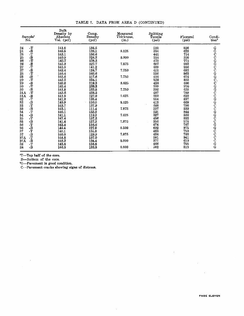
TABLE 7. DATA FROM AREA D (CONTINUED)
Bulk Density by Comp. Measured Splitting
Sample' Absolute Density Thickness, Tensile Flexural Condi-No. Vol. (pcf) (pcf) (in.) (psi) (psi) tion•
24 -T 141.0 134.5 510 826 G 24 -B 140.5 128.1 8.125 384 622 G 25 -T 143.1 136.6 441 714 c 25 -B 140.9 124.2 8.000 216 350 c 26 -T 142.7 138.3 470 771 G 26 -B 145.3 127.7 7.875 607 983 G 27 -T 145.5 141.2 609 986 c 27 -B 142.4 124.7 7.750 421 682 c 28 -T 146.4 14o.6 536 863 G 28 -B 145.6 117.6 7.750 416 674 G 29 -T 142.5 134.1 528 855 c. 29 -B 140.0 119.3 8.625 426 690 c 30 -T 145.4 13.8.3 599 970 G 30 -B 141.8 123.5 7.7.50 392 635 G 31A -T 143.6 138.5 487 789 c 31A -B 141.9 127.0 7.625 383 620 c 32 -T 141.8 135.4 554 897 G 32 -B 140.9 130.0 8.125 413 669 G 33 -T 143.7 137.9 488 790 c 33 -B 143.1 111.4 7.875 327 530 c 34 -T 140.i 133.2 521 844 G 34 -B 141.1 119.3 7.625 327 530 G 35 -T 147.4 137.2 496 803 c 35 -B 141.4 127.3 7.875 356 576 c 36 -T 142.4 136.6 474 767 G 36 -B 144.4 127.0 8.500 602 975 G 37 -T 140.1 135.8 463 750 c 37 -B 140.8 129.9 7.875 434 703 c 37A -T 144.8 137.0 581 941 c 37A -B 142.3 124.4 8.000 377 610 c 38 -T 143.6 136.8 466 755 G 38 -B 146.5 133.8 8.000 502 813 G
'T-Top half of the core. B-Bottom of the core. •a-Pavement in good condition. C-Pavement cracks showing signs of distress.
PAGE ELEVEN

TABLE 8. STATISTICAL ANALYSIS OF DATA FROM AREA D
Coefficient Average Median Standard of Variation No. of
Parameter Value Value Deviation Variance (percent) Values
Bulk Density (top) (pvt. sat.)-pcf 142.3 142.3 2.20 4.83 1.5 19 Bulk Density (bottom) (pvt. sat.)-pcf 142.8 142.5 2.06 4.26 1.4 19 Bulk Density (top) (pvt. distress)-pcf 142.6 142.5 2.47 6.12 1.7 21 Bulk Density (bottom) (pvt. distress)-pcf 140.8 140.9 1.68 2.82 1.2 21 Bulk Density (overall) (pvt. sat.)-pcf 142.6 142.4 2.12 4.48 1.5 38 Bulk Density (ove·rall) (pvt. distress)-pcf 141.7 141.8 2.28 5.18 1.6 42 Bulk Density (top) (all conditions)-pcf 142.5 142.4 2.32 5.38 1.6 40 Bulk Density (bottom) (all conditions )-pcf 141.8 141.6 2.11 4.46 1.5 40 Comp. Density (top) (pvt. sat.)-pcf 13.5.3 136.1 3.92 15.38 2.9 19 Comp. Density (bottom) (pvt. sat.)-pcf 125.9 127.0 5.78 33.44 4.6 19 Comp. Density (top) (pvt. distress)-pcf 136.1 136.6 2.77 7.67 2.0 21 Comp. Density (bottom) (pvt. distress)-pcf 123.3 125.9 6.36 4o.42 5.2 21 Comp. Density (overall) (pvt. sat.)-pcf 130.6 132.9 6.80 46.18 5.2 38 Comp. Density (overall) ( pvt. distress) -pcf 129.7 130.2 8.10 65.67 6.3 42 Comp. Density (top) (all conditions)-pcf 135.7 136.4 3.35 11.22 2.5 40 Comp. Density (bottom) (all conditions)-pcf 124.5 126.0 6.16 37.93 5.0 40 f,.' (top) (pvt. sat.)-psi 479.4 472.0 73.90 5461.01 15.4 19 r.. (bottom) (pvt. sat.)-psi 414.1 392.0 96.17 9248.75 23.2 19 f,. (top) (pvt. distress)-psi 485.9 487.0 64.19 4120.88 13.2 21 r.. (bottom) (pvt. distress )-psi 353.5 356.0 95.98 9211.83 27.2 21 f,. (overall) (pvt. sat.)-psi 446.7 452.5 90.83 8249.68 20.3 38 f ,. (overall) (pvt. distress)-psi 419.7 427.5 104.86 10995.01 25.0 42 f •• (top) (all conditions)-psi 482.8 473.0 68.15 4644.65 14.1 40 f,v (bottom) (all conditions)-psi 382.3 380.0 99.66 9932.84 26.1 40 Flexure Str. (top) (pvt. s!l!t.)-psi 776.5 767.0 119.45 14267.33 15.4 19 Flexure Str. (bottom) (pet. sat.)-psi 670.6 635.0 155.79 24269.21 23.2 19 F:lexure Str. (top) (pvt. distress)-psi 786.8 789.0 103.98 10812.30 13.2 21 Flexure Str. (bottom) ( pvt. distress) -psi 572.4 576.0 155.47 24170.81 27.2 21 Flexure Str. (overall) (pvt. sat.}-psi 723.6 733.0 147.05 21623.84 20.3 38 Flexure Str. (overall) (pvt. distress)-psi 679.6 692.5 169.84 28845.41 25.0 42 Flexure Str. (top) (all conditions)-psi 781.9 769.0 110.26 12157.26 14.1 40 Flexure Str. (bottom) (all conditions)-psi 619.1 615.0 161.45 26065.44 26.1 40
'Splitting Tensile Strength.
PAGE TWELVE
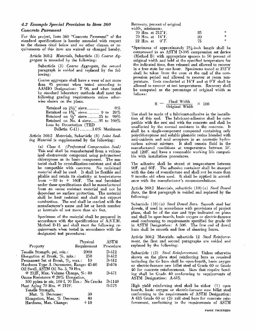
4.2 Example Special Provision to Item 360 Concrete Pavement
For this project, Item 360 "Concrete Pavement" of the standard specifications is hereby amended with respect to the clauses cited below and no other clauses or requirements of this item are waived or changed hereby.
Article 360.2 Materials, Subarticle (3) Coarse Aggregate is amended by the following:
Subarticle (3) Coarse Aggregate, the second paragraph is voided and replaced by the following:
Coarse aggregate shall have a wear of not more than 45 percent when tested according to AASHO Designation: T 96, and when tested by standard laboratory methods shall meet the following grading requirements unless otherwise shown on the plans.
Retained on 2%" sieve ........... . Retained on 1-%" sieve ............ 0 to
O% 20% 90%
100% Retained on lf2" sieve ............ 25 to Retained on No. 4 sieve ........ 95 to Loss by Decantation (THD
Bulletin C-ll) ............ 1.0% Maximum
Article 360.2 Materials, Subarticle (8) !oint Sealing Material is supplemented by the following:
(e) Class 4. (Preformed Compression Seal) This seal shall be manufactured from a vulcanized elastromeric compound using polymerized chloroprene as its basic component. The material shall be crystallization-resistant and shall be compatible with concrete. No reclaimed material shall be used. It shall be flexible and pliable and retain its elasticity at temperatures from -30 to + 160F. The seal furnished under these specifications shall be manufactured from an ozone resistant material and not be dependent on surface protection. The material shall be heat resistant and shall not support combustion. The seal shall be marked with the manufacturer's name and lot or batch number at intervals of not more than six feet.
Specimens of the material shall be prepared in accordance with the specifications of A.S.T.M. Method D-15 and shall meet the following requirements when tested in accordance with the designated test procedures:
Property Physical
Requirement
Tensile Strength, psi, min.: 2000 Elongation at Break, %, min.: 250 Permanent Set at Break, %_, max.: 10 Hardness Type A Durometer, Range: 45-60 Oil Swell, ASTM Oil No. 3, 70 Hrs.
@ 212F, Max. Volume Change, %: 80 Ozone Resistance @ 20% Elongation,
300 pphm in air, 100 f, 70 Hrs.: No Cracks Heat Aging 70 Hrs. @ 212F.
Tensile Strength, Max. % Decrease:
Elongation, Max. % Decrease: Hardness, Max. Change:
30 40
+10
ASTM Procedure
D-412 D-412 D-412 D-676
D-471
D-ll49 D-573
Recovery, percent of original width, minimum:
70 Hrs. at 212°F. 70 Hrs. at 14°F. 22 Hrs. at 0°F.
85 80 75
* * *
*Specimens of approximately 2%-inch length shall be compressed in an ASTM D-395 compression set device (Method B) with appropriate spacers to 50 percent of original width and held at the specified temperature for the indicated time, then released and allowed to recover in a free state for one hour. Specimens tested at 212oF shall be taken from the oven at the end of the compression period and allowed to recover at room temperature. Tests conducted at 14oF and at OoF shall be allowed to recover at test temperatures. Recovery shall be computed as the percentage of original width as follows:
Final Width R = X 100
Original Width
. Use shall be made of a lubricant,adhesive in the installation of this seal. The lubricant-adhesive shall be compatible with the seal and with the concrete and shall be unaffected by the normal moisture in the concrete. It shall be a single-component compound containing only polychloroprene and soluble phenolic resins blended with anti-oxidents and acid acceptors in an aromatic hydrocarbon solvent mixture. It shall remain fluid in the manufactured conditions at temperatures between SF. and 120F. and have a reasonable working life compatible with installation procedures.
The adhesive shall be stored at temperatures between SOF. and 80F. The adhesive container shall be stamped with the date of manufacture and shall not be more than 9 months old when used. It shall be applied in accordance with the manufacturer's recommendations.
Article 360.2 Materials, subarticle ( 10) (a) Steel Dowel Bars, the first paragraph is voided and replaced by the following:
Subarticle (10) (a) Steel Dowel Bars. Smooth steel bar dowels, if used in accordance with provisions of project plans, shall be of the size and type indicated on plans and shall be open-hearth, basic oxygen or electric-furnace steel conforming to requirements specified for grade 60 in ASTM Designation: A 306. The free end of dowel bars shall be smooth and free of shearing burrs.
Article 360.2 Materials. subarticle 12 Steel Reinforcement, the first and second paragraphs are voided and replaced by the following:
Subarticle (12) Steel Reinforcement. Unless otherwise shown on the plans steel reinforcing bars as required including the tie bars shall be open-hearth, basic oxygen or electric-furnace new billet steel of Grade 60 or Grade 40 for concrete reinforcement. Bars that require bending shall be Grade 40 conforming to requirements of ASTM Designation: A-615.
High yield reinforcing steel shall be either ( 1) open hearth, basic oxygen or electric-furnace new billet steel conforming to the requirements of ASTM Designation: A 615 Grade 60 or (2) rail steel bars for concrete reinforcement, conforming to the requirements of ASTM
PAGE THIRTEEN

Designation: A 616 Grade 60. (Bars produced by piling method will not he accepted.) High yield reinforcing steel bars shall he further identified by a special marking rolled into each bar. Unless otherwise designated on plans, all reinforcing steel shall he deformed bars conforming to the requirements of pertinent ASTM Specifications.
Where prefabricated deformed wire mats are specified or permitted, the wire shall he cold worked deformed steel wire conforming to the requirements of ASTM Designation: A 496, except that steel shall he made by open-hearth, electric-furnace, or basic oxygen processes. The prefabricated deformed wire mats shall conform to the requirements of ASTM Designation: A 497, except that all wires used shall he deformed and transverse wires shall project beyond the centerline of each edge longitudinal wire as specified on the plans and in these specifications. Mats that have been bent or wires dislocated or parted during shipping or project handling shall he realigned to within one,half inch of the original horizontal plane of the mat. Mats with any portion of the wires out of vertical alignment more than one-half inch after realignment and/or wires dislocated or mutilated so that, in the opinion of the Engineer, they do not represent the original mat, shall he rejected. The mats may he clamped or wired so that the mats will retain the horizontal and vertical alignment as specified by the plans or as approved by the Engineer. Deformed wire may he used for tie bars and load transfers that require bending. The nominal size and area and the theoretical weight of reinforcing steel wires covered by this provision are as listed in Table l.
Article 360.2 Materials is supp1emented by the following: In addition to the requirements of ASTM Designation C 150, the specific surface area of the cement shall not exceed 2000 square centimeters per gram as measured by the Wagner Turbidimeter in accordance with Text Method Tex 310-D.
Adequate storage facilities shall he provided for all approved materials. The intermixing of nonapproved materials with approved materials either in stockpiles or in bins will not he permitted. Aggregates from different sources shall he stored in different stockpiles unless otherwise approved by the Engineers.
Aggregates shall he stockpiled in such a manner to prevent segregation and maintained as nearly as possible in a uniform condition of moisture.
Each aggregate stockpile shall he reworked with suitable equipment at such times as required by the Engineer to remix the material to provide uniformity of the stockpile. Article 360.3 Equipment, is hereby amended by the following:
Suharticle ( 4) , Mixer, is voided and replaced by the following:
Suharticle ( 4) Mixer. The mixer furnished may he either a paving mixer (operated at the site of construction or centrally located) or a stationary mixer (central mixer) that will produce adequately mixed concrete meeting the specified requirements. The mixer, or mixers, shall conform to the following requirements.
Each mixer shall have attached in a prominent place a manufacturer's plate showing the rated capacity
PAGE FOURTEEN
TABLE 1. DIMENSIONAL REQUIREMENTS FOR DEFORMED STEEL WIRE FOR CONCRETE REIN
FORCEMENT
NOMINAL DIMENSIONS
Cross Sec-
Unit tional Deformed Weight Area
Wire Pounds Diam. Sq. Perimeter Size No. Per Ft. Inches Inches Inches
1 2 3~ 4 5
D-1 .034 .113 .01 .355 D-2 .068 .159 .02 .499 D-3 .102 .195 .03 .612 D-4 .136 .225 .04 .706 D-5 .170 .252 .05 .791 D-6 .204 .276 .06 .867 D-7 .238 .298 .07 .936 D-8 .272 .319 .08 1.002 D-9 .306 .338 .09 1.061 D-10 .340 .356 .10 1.118 D-11 .374 .374 .11 1.174 D-12 .408 .390 .12 1.225 D-13 .442 .406 .13 1.275 D-14 .476 .422 .14 1.325 D-15 .510 .437 .15 1.372 D-16 .544 .451 .16 1.416 D-17 .578 .465 .17 1.460 D-18 .612 .478 .18 1.501 D-19 .646 .491 .19 1.542 D-20 .680 .504 .20 1.583 D-21 .714 .517 .21 1.624 D-22 .748 .. 529 .22 1.662 D-23 .782 .541 .23 1.700 D-24 .816 .553 .24 1.737 D-25 .850 .564 .25 1.772 D-26 .884 .575 .26 1.806 D-27 .918 .586 .27 1.841 D-28 .952 .597 .28 1.876 D-29 .986 .608 .29 1.910 D-30 1.020 .618 .30 1.942 D-31 1.054 .628 .31 1.973
Col. 1. The number following the prefix D identifies the nominal cross-sectional area of the deformed wire in hundredths of a square inch. Fractional sizes are also available between the sizes listed.
Col. 2. The unit weight in pounds per foot is obtained by multiplying the cross-sectional area in square inches by 3.4.
Col. 3. The nominal diameter of a deformed wire is equivalent to the diameter of a plain wire having the same weight per foot as the deformed wire.
Col. 4. The cross-sectional area is based on the nominal diameter. The area in square inches may be cal-culated by dividing the weight per .lineal inch of specimen in pounds by 0.2833 (weight of 1 cu. in. of steel), or by dividing the weight per lineal foot of specimen in pounds by 3.4 (weight of steel 1 in. square and 1 ft. long) .
of the drum in terms of volume of mixed concrete and the recommended speed of rotation of the mixing drum or blades.
The stationary mixer (central mixer) shall he operated at the manufacturer recommended speed.
The size of the paving mixer shall not he less than that of a 27-E paver, as established by the Mixer Manufacturer's Bureau of the Associated General Contractors. The paving mixer shall he operated at a drum speed of not less than 16 revolutions per

minute and not more than 22 revolutions per minute. Pick-up and throw-over blades in the drum of the mixer shall be replaced when worn down % inch or more.
The mixer shall be equipped with an approved automatic device for satisfactorily timing the mix and locking the discharging device in order to prevent the discharging of the mixer before the end of the required mixing period. This timing device shall operate a sounding device to signal plainly the completion of the mixing time.
Multiple drum mixers will be permitted provided their operation is properly synchronized. The mixing time shall be determined exclusive of the time required to transfer concrete from one drum to the next drum.
Each mixer shall be equipped with a water measuring device so constructed that it will measure the water within 1 percent of the total amount required for each batch. Unless the water is to be weighed, the water measuring equipment shall include an auxiliary tank with a capacity greater than that of the measuring tank, and from which the measuring tank will be filled by gravity flow. The measuring tank shall be open to the atmosphere and shall be so placed and constructed that the water for a batch can be discharged into a calibrated tank or weighing device for checking the accuracy of water measurement without seriously delaying the paving operations. The Contractor shall have a calibrated tank or weighing device available at all times at a location satisfactory to the Engineer.
If a paving mixer is furnished and operated at the site of construction, it shall be equipped with a power controlled boom and bucket, so designed as to permit uniform distribution of the concrete for the full width between pavement forms. Alternate equipment for distributing concrete may be substituted when approved by the Engineer in writing, provided uniform distribution is obtained without segregation.
If central mixed concrete is used on the project, the Contractor shall provide equipment designed to provide uniform distribution of the concrete for the full width between pavement forms without segregation.
Transit mixing will not be allowed on this project except for small or irregular areas approved by the Engineer.
Subarticle (5) Hauling Equipment, is supplemented by the following:
If a central mixer is used, concrete may be transported to the point of delivery in truck agitators or nonagitating trucks.
If truck agitators are used, they shall be of the following types:
(a) Horizontal axis, revolving drum.
(b) Inclined axis, revolving drum.
(c) Open top, revolving blade or paddle.
(d) Alternate agitating hauling equipment ap-proved by the Engineer in writing.
The drum or agitating blades shall be actuated by an engine mounted as an integral part of the unit for the purpose of rotating the drum or agitating blades. It shall be capable of being governed accurately for the desired speed of rotation and be in satisfactory working condition. As an exception, where the truck agitator is equipped with a transmission that will govern the speed of the drum or agitating blades within the specified rpm, no seperate engine for rotating the drum will be required. Truck agitators shall be equipped with facilities to readily permit access for inspection, cleaning, and repair of blades.
Each truck agitator shall have attached, in a prominent place, by the manufacturer, a metal plate or plates on which are plainly marked the various uses for which the unit is designed. The data shall include speed of rotation of drum or agitating blades for agitation and the capacity of the unit.
If non-agitator trucks are used, they shall conform to the following requirements:
The bed of the non-agitating hauling equipment shall be a smooth, mortar-tight, metal container. The hauling equipment shall be capable of delivering the concrete to the site of the work in a thoroughly mixed and uniform mass and capable of discharging the concrete at a satisfactory controlled rate without segregation.
The non-agitating equipment shall be of sufficient capacity to transport one or more regnlar size batches and approved by the Engineer.
If in the opinion of the Engineer any appreciable segregation or accumulation of excess water and/ or mortar occurs on the surface of the concrete, this may be cause for rejection and this method of transporting the concrete to the point of delivery shall be suspended as directed by the Engineer.
Subarticle (8) Mechanical Vibratory Equipment is voided and replaced by the following:
All concrete placed for pavement shall be consolidated by approved mechanical vibrators operated ahead of the transverse finishing machine and designed to vibrate the concrete internally and/ or from the surface. Unless otherwise shown on the plans, vibrators of the surface-pan type will be used for two-lift placement of concrete and the internal type will be used for full-depth placement. Vibratory members shall extend across the pavement practically to, but shall not come in contact with the side forms. Mechanically-operated vibrators shall be mounted in such manner, as not to come in contact with the forms of reinforcement and not to interfere with the transverse or longitudinal joints. The internal-type vibrators shall be equipped with synchronized vibratory units. Separate vibratory units shall be spaced at sufficiently close intervals to provide uniform vibration and consolidation to the entire width of the pavement. The frequency of the internal type vibratory units and the method of operation shall be as determined by the Engineer.
PAGE FIFTEEN

The Contractor shall have a satisfactory tachometer available for checking the vibratory elements. The pan type vibratory units shall apply the vibrating impulses directly to the surface of the concrete. The operating frequency shall be not less than 3500 cycles not more than 4200 cycles per minute. The Contractor shall have a satisfactory tachometer available for checking the speed of the vibratory elements.
The pavement vibrators shall not be used to level or spread the concrete, but shall be used only for purposes of consolidation. The vibrators will not be operated where the surface of the concrete, as spread, is below the elevation of the finished surface of the pavement and the vibrators shall not be operated for more than 15 seconds while the machine upon which they are installed is standing still.
Approved hand manipulated mechanical vibrators shall be furnished in the number required for provision of proper consolidation of the concrete along forms, at joints and in areas not covered by mechanically controlled vibrators. These vibrators shall be sufficiently rigid to insure control of the operating position of the vibrating head.
Subarticle (9) Finishing Equipment. Section (b) The Longitudinal Finishing Machine, the fifth paragraph is voided and replaced by the following:
Unless otherwise specified on plans, the Contractor shall furnish a burlap drag for finishing the pavement. The burlap drag shall consist of two or more plies of burlap fastened to a bridge to form a continuous strip of burlap the full width of the pavement and with approximately two feet of its width in contact with the pavement surface. Burlap drags shall be maintained clean and free of encrusted mortar.
Article 360.3 Equipment and Article 360.8 Spreading and Finishing are supplemented by the following:
Spreader, is hereby added.
A self-powered concrete spreader of a type approved by the Engineer shall be required on this project. If a central-mix concrete plant is used, the spreader must be capable of receiving the concrete from the hauling equipment and uniformly distributing the concrete on the subgrade without segregation, unless other methods producing equal results are approved by the Engineer in writing. Depositing concrete on the subgrade from hauling equipment will not be permitted except for irregular pavement sections where approved by the Engineer.
Optional Method and Equipment for Placing and Finishing Concrete Pavement
In lieu of construction methods employing forms, spreading, consolidating, finishing and floating equipment required in this specification, the contractor, if he so elects, may use a "Traveling Form Paver" (also known by various other trade names such as "Formless Paver," "Slip Form Paver," etc.). If this method of construction is elected, all requirements of this specification in regard to subgrade and pavement tolerances, pavement depth, alignments, workmanship, etc., shall be met in full.
PAGE SIXTEEN
In addition to the applicable provisions o£ this specification, the following requirements shall govern when a traveling form paver is employed.
l. Equipment
If a "Traveling Form Paver" proves inadequate in the opinion of the Engineer in providing a pavement which meets the plans and specifications in all respects, the use shall be immediately discontinued when so ordered by the Engineer.
The traveling paver shall be equipped with a longitudinal transangular finishing float (also known by various trade names such as "V-Finisher," "Lewis Transangular Finisher," C.M.I. tube float Etc.) attached to the paver and adjustable to crown and grade. The float shall extend across the pavement practically to the side forms.
2. Construction Methods: Prior to beginning pav· ing operations, the Contractor shall insure that a continuous deposit of concrete can be made at the paver to minimize starting and stopping.
Locations inaccessible to a traveling paver or locations having horizontal or vertical curvature that a traveling· paver cannot negotiate shall be paved using conventional means.
Where the plans require tie bars to be installed for adjacent paving, the bars shall be securely tied and supported to prevent displacement, or the tie bars may be installed with an approved bar inserter, mounted on the traveling-form paver. The Contractor will be required to replace at his expense any pavement in which tie bars assume a final position other than that shown on the plans. Tie bars which require bending after concrete has been placed shall not be bent until the concrete has cured three days or until such time as the Engineer may direct.
3. Curing. The concrete pavement, except that to be overlaid by asphaltic concrete, shall be cured with a Type II white pigmented curing compound in accordance with the requirements of the Item, "Membrane Curing."
Article 360.3 Equipment and 360.8 Spreading and Finishing are supplemented .by the following:
Where the pavement width is irregular, or where the area to be paved is isolated or narrow in width, other paving equipment than that specified above will be permitted when approved by the Engineer unless otherwise shown on plans.
Article 360.4 Proportioning of Concrete, is amended by the following:
Subarticle (5) Mix Design, the fifth paragraph is voided and replaced by the following:
For mixing the concrete to be used in making the preliminary test specimens, the Contractor shall furnish and operate the mixer approved for use on this project. A minimum one cubic yard batch shall be mixed or a batch of sufficient size to afford proper mixing, whichever is the greater. In lieu of the above mixer and procedure, the Contractor may furnish a portable mixer of sufficient rated capacity to mix a minimum three-sack batch; in which case,

the batch mixed for the preliminary test shall not be less than the rated capacity of the mixer furnished.
A coating batch will be mixed prior to mixing for test beams as prescribed in THD Bulletin C-11. No additional compensation will be allowed for equipment, materials or labor involved in making preliminary test specimens.
Subarticle (5) Mix Design is supplemented by the following:
The cement furnished for preliminary tests shall have a specific surface area within a range of 1600 to 1900 square centimeters per gram.
A change in the specific surface of the cement of more than 100 square centimeters per gram from that furnished for preliminary tests may require a new mix design. The cement shall be sampled and tested in accordance with the Texas Highway Department, Manual of Testing Procedures, and the Contractor shall furnish to the Engineer with each shipment a statement as to the specific surface area of the cement expressed in square centimeters per gram.
Subarticle ( 6) Test Specimens, is voided and replaced by the following:
"Unless otherwise specified on the plans, test beams for flexural strength value shall be taken in accordance with THD Bulletin C-11. Additional beams may be made as required by concrete placing conditions, or for adequately determining the strength of concrete where the early opening of the pavement to traffic is dependent upon concrete strength tests. No extra compensation will be allowed for materials and work involved in fulfilling these requirements."
Article 360.6 Concrete Mixing and Placing, is amended by the following:
Subarticle (1) Mixing Methods is supplemented by the following:
Transit mixing will not be allowed on this project except for small or irregular areas approved by the Engineer.
Subarticle (2) Mixing, is supplemented by the following:
The Engineer may increase the minimum mixing time to that necessary to produce thoroughly mixed concrete based on inspection or appropriate uniformity tests. The mixing time may be varied at any time as necessary to produce acceptable concrete.
If a central mixer is u;ed, the concrete shall be discharged into the specified hauling equipment and delivered to the road site. If truck agitators are used, the concrete shall be continuously agitated at not less than one nor more than six rpm as directed by the Engineer.
Subarticle (3) Placing, is supplemented by the following:
If a central mixer is used, the Contractor shall pro-
vide a system satisfactory to the Engineer for determining that concrete delivered to the road meets the specified requirements for mixing and time of placing.
If a central miXmg plant is used, two mixers will not be required where the double strike-off method is employed.
If in the opinion of the Engineer, the temperature, wind and/ or humidity conditions are such that the quality of the concrete will not be adversely affected, the specified placing time may be extended to a maximum of 45 minutes.
Subarticle ( 4) Reinforcing Steel and Joint Assemblies, the first paragraph is voided and replaced by the following:
All reinforcing steel, including steel wire fabric reinforcement, tie bars, dowel bars, and load transmission devices used in accordance with plan provisions shall be accurately placfld and secured in position in accordance with details shown on plans. Reinforcing bars shall be securely wired together at alternate intersections, following a pattern approved by the Engineer; and at all splices, and shall be securely wired to each dowel intersected. When wire fabric is used, it replaces only the longitudinal and transverse bars and shall be securely wired together at all splices and to each dowel intersected. Tie bars shall be installed in the required position by the method and device shown on plans, or by approved method and device equivalent thereto. Bar coatings required by plans, and of material specified, shall be completed and the bars and coating shall be free of dirt or other foreign matter at the time of installation in the concrete.
Article 360.7 JOINTS, Subarticle (1) General is supplemented by the following:
If necessary for proper installation of the sealer, excessive spalling of the joint groove shall be repaired to the satisfaction of the Engineer in the manner which he prescribes.
Article 360.7 JOINTS, Subarticle (3) Weakened Plane Joints paragraph (c), Joint Sealers, is voided and replaced by the following:
Unless otherwise specified on the plans either Class 1-a, Class 1-b, Class 2, Class 3 or Class 4 materials, designated by Article 360.2(8) "Joint Sealing Materials," may be used at the option of the Contractor.
Article 360.7 JOINTS, is supplemented by the following: Class 4 Material. After the joints in the hardened concrete have been sawed, repaired (if necessary) , and cleaned to the satisfaction of the Engineer, the material shall be installed into each joint by means of an appropriate hand or power operated installation device using the lubricant-adhesive specified. The seal shall be installed in a compressed condition and shall be free of an objectionable amount of curling and twisting during installation in the joint groove. It shall be of such material and so installed that it will effectively seal joints in concrete against
PAGE SEVENTEEN

water, dirt, and stones throughout repeated cycles of expansion and contraction. Stretching of the compression seal during installation in the joint will not be permitted.
Article 360.8 Spreading and Finishing is amended by the following:
Subarticle (1) Machine Finishing, the seventh and eighth paragraphs are voided and replaced by the following:
After completion of the straightedge testing, and just before the concrete becomes non-plastic, the surface shall be finished with an approved burlap drag unless otherwise indicated on plans. This operation shall produce a uniform surface of a gritty texture.
After completion of finishing and about the time the concrete becomes hard, the edge of the slab and joints shall be carefully finished as directed by the Engineer and the pavement shall be left smooth and true to line.
Article 360.13, PAYMENT, the first paragraph is voided and replaced by the following:
360.13 Payment. The work performed and materials furnished as prescribed by this item and measured as provided under "Measurement" will be paid for at the unit price bid for "Concrete Pavement," Concrete Pavement (High Strength)," "Concrete Pavement (High Yield Steel)," "Concrete Pavement (Deformed Wire Mat)" and "Monolithic Curb" (when pavement is measured by the square yard), as required, or the adjusted unit price for pavement of deficient thickness as provided under "Penalty for Deficient Pavement Thickness," which price shall be full compensation for shaping and fine grading the roadbed, including furnishing and applying all water required; for furnishing, loading and unloading, storing, hauling and handling all concrete ingredients, including all frei~ht and royalty involved; for mixing, placing, finishing, sawing, cleaning and sealing joints, and curing all concrete; for furnishing and installing all reinforcing steel; for furnishing ·an materials for sealing joints imd placing longitudinal, expansion, and weakened plane joints, including all steel dowel caps and load transmission devices required, and wire and devices for placing, holding and supporting the steel bars, load transmission devices and joint filler material in proper position, for coating steel bars where required by plans, and for all manipulations, labor, equipment, appliances, tools, traffic provisions and incidentals necessary to complete the work.
PAGE EIGHTEEN
4.3 References
1. Powers, T. C., "Vibrated Concrete," presented at the 29th Annual Convention, Chicago, Feb. 21-23, 1933, Proceedings, Journal of the American Concrete Institute, June 1933, pp. 373-381.
2. Kirkham, R. H. H., "Influence of Vibrating Beams on Compaction of Concrete Surfacings," Materials and Construction, pp. 340-351.
3. Larnach, William J ., '.:,Changes in Bond Strength Caused by Re-Vibration of Concrete and the Vibration of Reinforcement," Magazine of Concrete Research, July 1952, pp. 17-31.
4. Taylor, W. H., Concrete Technology and Practice, 2nd ed., (Chapter 23, "Mechanical Compaction"), American Elsievier Publishing Co., Inc., New York, N. Y., 1967, 650 pp.
5. "Consolidation of Concrete," reported by ACI Committee 609, Journal of the American Concrete Institute, April 1960, No. 10, Vol. 31.
6. Clair, Miles N., "The Use of Vibration in the Manufacture of Concrete Products," presented at the 29th Annual Convention, Chicago, Feb. 21-23, 1933, Proceedings, Journal of the American Concrete Institute, June, 1933, pp. 383-390.
7. Reagel, F. V., "Vibratory Finishing Machine for Concrete Pavements," presented at the 29th Annual Convention, Chicago, Feb. 21-23, 1933, Proceedings, Journal of the American Concrete Institute, June 1933, pp. 391-396.
8. ASTM C 215, "Fundamental Transverse Longitudinal and Torsional Freque11cies of Concrete Specimens," 1968 Book of ASTM Standards, Part 10, Concrete and Mineral Aggregates, American Society for Testing and Materials, Philadelphia, Pa., Oct. 1968, pp. 155-159.
9. ASTM C 496, "Splitting Tensile Strength of Molded Concrete Cylinders," 1968 Book of ASTM Standards, Part 10, Concrete and Mineral Aggregates, American Society for Testing and Materials, Philadelphia, Pa., 1968, pp. 351-354.
10. McCullough, B. F., "A Pavement Overlay Design System Considering Wheel Loads, Temperature Changes, and Performance," Ph.D. Dissertation, University of California, Berkeley, California, 1969.
11. Shelby, M. D., and McCullough, B. F., "Fourth Year Progress Report on Experimental CRCP in Walker County," Departmental Research Report, Highway Design Division, Texas Highway Department, March 1965, 34, pp.