Embed Size (px)
Citation preview
Feed Pelleting Reference Guide Section 4: Ingredient Considerations
Chapter 18: Considerations for Aquaculture
Considerations for Pelleting for
Aquaculture BY EUGENIO BORTONE, PH.D, PAS, DPL. ACAS
REVIEWED AND EDITED BY CHARLES STARK, ADAM FAHRENHOLZ, AND CASSANDRA JONES
Global production of aquafeed is approximately
6.3 million metric tonnes (MMT) per year (FAO,
2012). Of this total, approximately 44 MMT is
inland production and 19 MMT is marine
production. The growth in aquaculture will continue
as countries increase aquaculture production to meet
the demand for food production, specifically as a
protein source.
The aquafeed mill
Feed mills designed to produce aquafeed have
major differences when compared to traditional
animal feed mills. To understand the differences, it
is necessary to have a basic understanding of an
aquafeed plant layout. Figures 18-1, 18-2 and 18-3
show the three major operational or cost centers of a
plant designed to produce shrimp or fin fish feeds.
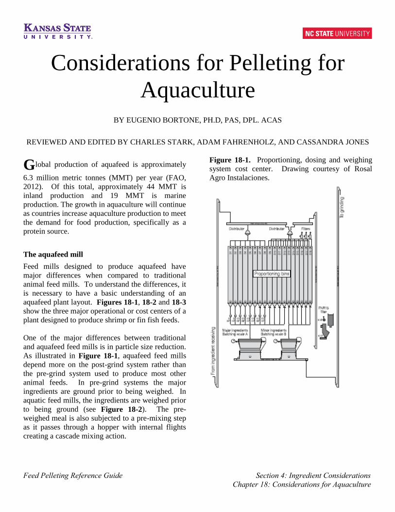
One of the major differences between traditional
and aquafeed feed mills is in particle size reduction.
As illustrated in Figure 18-1, aquafeed feed mills
depend more on the post-grind system rather than
the pre-grind system used to produce most other
animal feeds. In pre-grind systems the major
ingredients are ground prior to being weighed. In
aquatic feed mills, the ingredients are weighed prior
to being ground (see Figure 18-2). The pre-
weighed meal is also subjected to a pre-mixing step
as it passes through a hopper with internal flights
creating a cascade mixing action.
Figure 18-1. Proportioning, dosing and weighing
system cost center. Drawing courtesy of Rosal
Agro Instalaciones.

Feed Pelleting Reference Guide Section 4: Ingredient Considerations
Chapter 18: Considerations for Aquaculture
Figure 18-2. Grinding and mixing cost centers.
Drawing courtesy of Rosal Argo Instalaciones.
Post-grinding process
A post-grinding system is necessary in aquatic feeds
because of the inclusion of difficult-to-grind
ingredients such as fishmeal. It allows the
production of a more uniform particle size. Another
advantage of the post-grinding system is that it does
not require storage for the individual ground
ingredients, and does not require a grinding process
for each ingredient.
Hammermills have long been used for particle size
reduction in the animal feed industry. A typical
hammermill for aquaculture feed applications will
have a motor rotational speed of 3,600 RPM, twice
as high as the speed used in most livestock and
poultry feeds.
Figure 18-3. Pelleting and extrusion cost centers.
Drawing courtesy of Rosal Argo Instalaciones.
For larval shrimp feeds it is necessary to reduce the
particle size of an ingredient or blend of ingredients
to as small as 100-150 microns, with a maximum of
5% retained on an 80-mesh Tyler screen. For
adequate feed conversion in growing shrimp it is
generally recommended that the average mean
geometric particle size be 250 microns, with a
maximum of 5% retained in a 60-mesh Tyler
screen.
Uniform particle size will also improve the moisture
and heat transfer during preconditioning of the feed
prior to pelleting. With a uniform particle size the
moisture distribution from steam condensation will
occur more evenly. If the particles are not uniform,
then the smaller ones, with a larger surface area,
will absorb more moisture and could tend to
produce “spotted” pellets that can have poor water
stability.
Feed Pelleting Reference Guide Section 4: Ingredient Considerations
Chapter 18: Considerations for Aquaculture
Another major difference between traditional and
aquatic feed production can be found in the
pelleting operation. Pellet mills in traditional feed
mills use shorter residence time (10-60 seconds)
preconditioners as compared to shrimp feeds that
require preconditioning times of three or more
minutes. The compression ratio used in the pellet
dies is also different. Shrimp feeds require
compression ratios of 20-24 (diameter of the bore
divided by the effective travel length), while poultry
and swine feeds require compression ratios of 10-
12. A higher compression of shrimp feeds is
required in order to produce highly water-stable
feeds. With increased compression, the production
capacity is reduced. Therefore, a pellet mill set up
to produce 30 MT/hr of poultry feed may only
produce 4-5 MT/hr of high-quality shrimp feed.
Formulation
The high protein levels of most aquafeeds are
achieved by using ingredients high in protein such
as fishmeal, shrimp head meal, squid meal, clam
meal and soybean meal. Soybean meal use has
increased considerably in an attempt to reduce feed
costs and lessen the demand on fishmeal. Many of
these high protein ingredients also have a high oil
content. When these ingredients are ground, their
high oil content can clog fine mesh screens. To
avoid this, it is recommended that ingredients high
in oil be ground together with low oil content
ingredient(s) such as cereal grains.
For shrimp feed manufacturing, the most common
low oil ingredients used in combination with protein
meals high in oil are whole wheat grain, wheat
flour, wheat gluten, and defatted soybean meal.
Because fibrous ingredients do not grind well,
wheat middlings and similar ingredients are not
used in shrimp formulations. Although the fiber
particles can be reduced in size to a point, because
they are flexible they can be pulled through the
screen holes by the air-assist system without being
reduced to the target particle size. These large fiber
pieces will act as avenues for water penetration, and
upon soaking, will expand, leading to the creation
of voids resulting in loss of pellet integrity. For
aquafeed manufacturing it is recommended that
high-fiber ingredients not exceed 3% of the total
formula.
Formulation can perhaps be better understood when
we consider feeding a 1 g shrimp. For this stage of
physiological development the shrimp will consume
approximately 12% of its body weight per day, or
approximately 0.12 g of feed. Every pellet or
crumble of feed should contain all the nutrients for
which the diet has been formulated. In the event
the ingredients are not mixed properly, reduced
growth rates, high morbidity and mortality, and
poor feed conversion could result.
Once the major ingredients are ground to the target
particle size, they are passed to the mixer where
other minor ingredients such as heat-labile vitamins
and some of the liquids are added. From the mixer,
the mixed formula meal is sent to the pelleting line
(Figure 18-3).
Mixing: Sequence of ingredient addition
The order in which ingredients are added to the
mixer can affect the mixing efficiency. The
sequence of addition will depend on the
formulation, type of ingredients, and the activation
of natural or synthetic binders. Particular attention
should be paid to the addition of binders to the mix.
In most cases, binding agents need to be activated
by water and by temperature. However, if a
hydrophobic liquid, such as oil (i.e., fish oil), is
added in the mixer and coats the synthetic or natural
binder, it will not be able to readily absorb water
and start development of its binding properties,
which can reduce the water stability of the pelleted
feed.
Aquaculture feed ingredients are added to the
mixer in the following order:
• All major ingredients in order from greatest to
least (fishmeal, soybean meal, cereal flours, etc.).
Allow some mixing time (1-2 minutes depending
on type of mixer) prior to adding the minor
ingredients (trace elements, vitamin pre-mixes,
etc.), which will also be added from greatest to
least.
Feed Pelleting Reference Guide Section 4: Ingredient Considerations
Chapter 18: Considerations for Aquaculture
• Once all the dry ingredients are added, they should
be mixed for a predetermined time before the
addition of liquid ingredients.
• To prevent clump formation, the liquid ingredients
must be sprayed onto the mixed feed as uniformly
as possible, with water being the first liquid added
because water must be internalized into the
particles, improving the binding capacity once
subjected to higher temperatures in the pelleting
or extrusion processes.
• After the water is added, other aqueous
ingredients should follow.
• Lipids should be added last to prevent coating the
particles and inhibiting the hydration of the starch
and other binding agents that may be present in
the formula.
• After all liquid ingredients are added, mix for a
predetermined time to ensure adequate dispersion.
Production basics for aquafeed
The most common mixer used in commercial
aquaculture feed manufacturing today is the
horizontal (Figure 18-4) mixers.
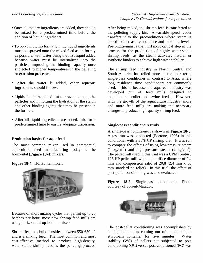
Figure 18-4. Horizontal mixer.
Because of short mixing cycles that permit up to 20
batches per hour, most new shrimp feed mills are
using horizontal drop-bottom mixers.
Shrimp feed has bulk densities between 550-650 g/l
and is a sinking feed. The most common and most
cost-effective method to produce high-density,
water-stable shrimp feed is the pelleting process.
After being mixed, the shrimp feed is transferred to
the pelleting supply bin. A variable speed feeder
transfers it to the preconditioner where steam is
added to increase temperature and moisture levels.
Preconditioning is the third most critical step in the
process for the production of highly water-stable
shrimp feeds, as the steam activates natural or
synthetic binders to achieve high water stability.
The shrimp feed industry in North, Central and
South America has relied more on the short-term,
single-pass conditioner in contrast to Asia, where
long residence time conditioners are commonly
used. This is because the aquafeed industry was
developed out of feed mills designed to
manufacture broiler and swine feeds. However,
with the growth of the aquaculture industry, more
and more feed mills are making the necessary
changes to produce high-quality shrimp feed.
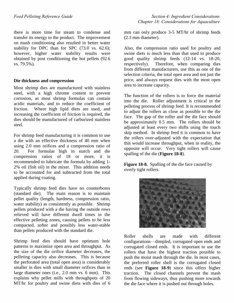
Single-pass conditioners study
A single-pass conditioner is shown in Figure 18-5.
A test run was conducted (Bortone, 1995) in this
conditioner with a 35% CP shrimp diet. It was run
to compare the effects of using low-pressure steam
(1 kg/cm2) and high-pressure steam (2 kg/cm2).
The pellet mill used in this trial was a CPM Century
125 HP pellet mill with a die orifice diameter of 2.4
mm and compression ratio of 20.8 (2.4 mm x 50
mm standard no relief). In this trial, the effect of
post-pellet conditioning was also evaluated.
Figure 18-5. Single-pass conditioner. Photo
courtesy of Sprout-Matador.
The post-pellet conditioning was accomplished by
placing hot pellets coming out of the die into a
styrofoam container for five minutes. Water
stability (WS) of pellets not subjected to post
conditioning (OC) versus post conditioned (PC) was

Feed Pelleting Reference Guide Section 4: Ingredient Considerations
Chapter 18: Considerations for Aquaculture
measured as percent dry matter left after four hours
of water immersion. For this method, 80% WS is
considered good and beyond 90% is considered
excellent.
Results indicated that, at a pressure of 2 kg/cm2,
conditioned mash temperature and pellet
temperature exiting the die were higher (95 vs.
92°C and 98 vs. 95°C) than at 1 kg/cm2 pressure. In
contrast, water stability (WS) was higher for low-
pressure (LP) pellets (75.2 vs. 68.0%). The higher
pellet temperature of high-pressure (HP) pellets is
due to lower moisture content, which in turn had
higher friction as they exited the die. This higher
temperature of HP pellets is also responsible for the
higher post conditioning temperatures achieved
(95.0 vs. 94.0°C).
Water stability for PC pellets was substantially
higher than for pellets cooled right after exiting the
die at the same pressure. However, there was no
difference in water stability for PC pellets at either
of the pressures tested (92.8 vs. 92.2). The results
clearly show an advantage in using post
conditioning and this should be considered,
especially in situations where double-pass
conditioners are not available.
A better alternative to the single-pass short retention
time conditioner is the double-pass (Figure 18-6),
and even triple-pass conditioner. Stacking
conditioners on top of each other reduces the total
length of the unit. Many poultry and swine
operations are turning their attention to double-pass
conditioners as a way to increase pellet durability,
reduce fines, increase pellet digestibility and as a
means for sanitizing the feed.
A disadvantage of multiple-pass conditioners is the
possibility of reduced mixing when the speed is
reduced or the paddle configuration is changed in an
attempt to increase dwell time. This dilemma can
be overcome by using double agitators that rotate at
different speeds, maintaining adequate mixing and
dwell times. This is known as the double-
differential conditioner (Figure 18-7).
Figure 18-6. Double-pass conditioner. Photo
courtesy of Sprout-Matador.
Figure 18-7. Double-differential conditioner. Photo
courtesy of Wenger, Inc.
A comparison between (Bortone, 1996) a Sprout-
Matador double-pass conditioner (DPC) and a CPM
single-pass (SPC) conditioner was made to
determine the effects of long (two minutes) vs. short
retention time (30 seconds) on shrimp feed water
stability. In this case, die specifications (2.4 mm x
50 mm working area, high-chrome die and closed-
end corrugated roller shells), formula (35% CP
high-wheat flour) and processing conditions were
equal. The pellet mills were the same brand of
equipment and were run at the same die speed side
by side. The steam was injected at 1.5 kg/cm2 of
pressure. In this trial, post-pellet conditioning
(PPC) of five minutes was tested for both DPC and
SPC.
Results indicated that a DPC achieved higher mash
conditioning temperatures than the SPC (97.5 vs.
82.4°C). Also, mash moisture was higher for DPC
than SPC (15.7 vs. 12.9%). These results
corroborated the advantage of dwell time on mash
temperature and moisture. This experiment
demonstrates that as the residence time increases,
Feed Pelleting Reference Guide Section 4: Ingredient Considerations
Chapter 18: Considerations for Aquaculture
there is more time for steam to condense and
transfer its energy to the product. The improvement
on mash conditioning also resulted in better water
stability for DPC than for SPC (73.0 vs. 62.6);
however, higher water stability results were
obtained by post conditioning the hot pellets (92.6
vs. 79.5%).
Die thickness and compression
Most shrimp dies are manufactured with stainless
steel, with a high chrome content to prevent
corrosion, as most shrimp formulas can contain
acidic materials, and to reduce the coefficient of
friction. Where high lipid diets are used, and
increasing the coefficient of friction is required, the
dies should be manufactured of carburized stainless
steel.
For shrimp feed manufacturing it is common to use
a die with an effective thickness of 40 mm when
using 2.0 mm orifices and a compression ratio of
20. For formulas high in starch and die
compression ratios of 18 or more, it is
recommended to lubricate the formula by adding 1-
2% oil (fish oil) in the mixer. This addition needs
to be accounted for and subtracted from the total
applied during coating.
Typically shrimp feed dies have no counterbores
(standard die). The main reason is to maintain
pellet quality (length, hardness, compression ratio,
water stability) as consistently as possible. Shrimp
pellets produced with a die having the outside rows
relieved will have different dwell times in the
effective pelleting zones, causing pellets to be less
compacted, softer and possibly less water-stable
than pellets produced with the standard die.
Shrimp feed dies should have optimum hole
patterns to maximize open area and throughput. As
the size of the die orifice diameter decreases, the
pelleting capacity also decreases. This is because
the perforated area (total open area) is considerably
smaller in dies with small diameter orifices than in
large diameter ones (i.e., 2.0 mm vs. 6 mm). This
explains why pellet mills with throughputs of 20
MT/hr for poultry and swine diets with dies of 6
mm can only produce 3-5 MT/hr of shrimp feeds
(2.3 mm diameter).
Also, the compression ratio used for poultry and
swine diets is much less than that used to produce
good quality shrimp feeds (12-14 vs. 18-20,
respectively). Therefore, when comparing dies
from different manufacturers, use this as one of the
selection criteria, the total open area and not just the
price, and always request dies with the most open
area to increase capacity.
The function of the rollers is to force the material
into the die. Roller adjustment is critical in the
pelleting process of shrimp feed. It is recommended
to adjust the rollers as close as possible to the die
face. The gap of the roller and the die face should
be approximately 0.5 mm. The rollers should be
adjusted at least every two shifts using the touch
skip method. In shrimp feed it is common to have
the rollers over-adjusted with the expectation that
this would increase throughput, when in reality, the
opposite will occur. Very tight rollers will cause
spalling of the die (Figure 18-8).
Figure 18-8. Spalling of the die face caused by
overly tight rollers.
Roller shells are made with different
configurations—dimpled, corrugated open ends and
corrugated closed ends. It is important to use the
rollers that have the highest traction possible to
push the moist mash through the die. In most cases,
the preferred roller shell is the corrugated closed
ends (see Figure 18-9) since this offers higher
traction. The closed channels prevent the mash
from flowing sideways, thus pushing more towards
the die face where it is pushed out through holes.

Feed Pelleting Reference Guide Section 4: Ingredient Considerations
Chapter 18: Considerations for Aquaculture
Figure 18-9. Corrugated shells closed ends. Photo
courtesy of Jacobson Inc.
The shells should be rotated at least twice during
the life of the die. It is also important to have each
die placed with its matching set of roller shells.
This is because the shells will conform to the wear
of the die, and if used with a different die, will not
have the same wear pattern, thus affecting
throughput and possibly damaging the die.
The shells can be fine groove (Figure 18-10) or
standard (Figure 18-11) groove configuration. For
moist meals, as in the case of shrimp feed, the fine
groove is the more desired one because it has good
traction due to greater surface area of contact and it
also provides a quieter run.
Figure 18-10. Fine groove shell.
Figure 18-11. Standard groove shell.
Pellets are cut as they exit the die. The knives used
to cut the pellets need to be as sharp as possible.
Dull blades will only knock off the pellets, creating
stress cracks that will cause the pellets to break into
smaller pieces with fines production. The stress
cracks also provide an avenue for water penetration,
which can result in poor water stability. As a
general rule, all blades need to be replaced at least
every other shift.
Post-pellet cooking
Why is water stability so improved with post
conditioning? As discussed previously, pellets
subjected to some form of post conditioning had
improved water stability. In those trials, post
conditioning was accomplished by just keeping the
pellets at their own temperature for a determined
period of time. The increments in time in which the
pellets are kept warm have two positive effects.
First, the pellets are not subjected to the sudden
change in temperature due to the cold draft of the
cooler that causes the pellets to contract rapidly.
The sudden contraction causes microscopic cracks
that are avenues for water penetration and result in
poor water stability. Post conditioning, as a very
slow cooling process, allows for the contraction to
occur very slowly and permits particles to come
together in a tight structure rather than the sudden
cooling process, which leaves these particles
separated (no maturation) with micro-cracks or
voids. Second, post conditioning provides the
means for further cooking the starches, which in
turn improves water stability. After all, the degree

Feed Pelleting Reference Guide Section 4: Ingredient Considerations
Chapter 18: Considerations for Aquaculture
of starch gelatinization is a time- and temperature-
dependent process.
Post-pellet cookers offer an alternative to
substantially improve shrimp feed water stability.
There is no published literature that shows a
scientific explanation as to why post conditioned
pellets have better water stability than pellets not
subjected to this treatment. However, research
(Bortone, 1995) with shrimp feeds using regular
pelleting, extrusion and expander and pelleting
technologies follow the same trend. No matter what
process is used, water stability is 10-20% better
when the pellets are subjected to a post cooking
time.
As pellets exit the die some expansion is exhibited,
but if allowed to cook slowly, the pellets’ diameter
starts to shrink. This shrinkage brings the particles
together, including starch granules, protein and even
other binding agents present in the formula. In
contrast, when pellets are subjected to an abrupt
change in temperature, as in the case of the pellets
immediately reaching the cooler, they do not have
time to shrink in size, and micro-cracks develop.
Post conditioners, or post-pellet cookers, are not
new in the Eastern hemisphere. These units of
operation have slowly made their way to the
Western hemisphere in the last five years, where
they have been recognized to improve pellet water
stability.
A few years ago, this unit was regarded as a “trade
secret,” but not so long ago feed manufacturers
learned about it and started implementing its use.
The main post-pellet conditioners used in the
shrimp feed industry in Asia were horizontal units.
These horizontal units were designed to retain the
pelleted feed for up to 20 minutes. The units can be
anything from slowly-moving drag conveyors to
large holding bins.
Horizontal post conditioners
These units may be considered a simple “box.” But
there is more to post conditioners. The units are
designed to either further heat the pellets via live
steam addition or keep them as hot as possible
(jacketed). Some units incorporate steam injection,
temperature control zones and PLC controls to
monitor temperature and humidity.
To understand the size of a horizontal unit we also
need to take into account the maximum capacity of
the pellet mill. This is the highest capacity at which
the “best quality” feed is made. Therefore, if the
pellet mill is known to produce pellets of high
quality at 3 MT/hr, with 10 minute residence time in
the post conditioner, then these parameters should
be used as a guideline to size the unit.
Figure 18-12 shows post conditioning time
optimization trials using styrofoam boxes to
simulate a post cooker unit. The boxes are labeled
5, 10, 15 and 20 minutes (Figure 18-13) and the
pellets were collected at a known capacity. This is
repeated at various pellet mill capacities to
determine the optimal capacity without reducing
pellet water stability.
Figure 18-12. Styrofoam box simulating a post
conditioning chamber.
Once the minimum residence time is estimated, one
can proceed to size the unit or use this information
to request the minimum residence time required
from the equipment vendor.

Feed Pelleting Reference Guide Section 4: Ingredient Considerations
Chapter 18: Considerations for Aquaculture
Figure 18-13. Styrofoam boxes labeled 5, 10, 15
and 20 minutes to measure the effect of post
cooking time at 4 MT/hr.
Calculate the space needed
How big does this unit need to be to hold the
product for 10 minutes? To determine the
dimensions of the bed needed to hold the product
for the required time, use the following equation:
Footprint area (FPA) = (rate × time/60) / (depth x )
For example:
Production rate = 3,000 kg
Feed density = 650 kg/m3
Desired bed depth of pellets = 0.3 meters
Post conditioning time = minimum 10 minutes
FPA = (3000 kg × (10 minutes/60 minutes)) /
(0.3 m × 650 kg/m3) = 2.56 m2
The total footprint for the bed can be a
combination of lengths and widths as shown on
Table 18-1.
Table 18-1. Settings for a 10 minute residence
time in a horizontal post conditioner.
Length, m Width, m Area, m2
2.56 1.00 2.56
2.84 0.9 2.56
3.20 0.8 2.56
3.66 0.7 2.56
4.27 0.6 2.56
5.12 0.5 2.56
The dimensions of the horizontal post conditioner
depend on the floor space available. The
dimensions can change considerably if the residence
time is doubled. This will practically require
double the space of the footprint or a change of bed
depth. One critical aspect to consider is the bed
width of the unit. The wider the bed, the shorter it
will be. If it is too wide, it will require an
oscillating arm feeder to evenly distribute the
pelleted feed across the bed width. This adds an
extra cost to the unit. Other important aspects to
consider are: Steam injection; jacketed sections to
maintain the temperature product; temperature
control thermocouples (closed-loop control); and
total moisture coming out of the post conditioner.
The latter is often overlooked and may result in
serious problems if live steam is injected. This can
result in high moisture in the finished product
because a cooler alone will not be able to remove
the excess.
Horizontal post conditioners can work well where
floor space is available, but when sizing a unit or
designing a new line, consider other important
aspects such as maintenance. Horizontal units
require more maintenance due to the large amount
of moving parts used. Also, they require more
cleaning to avoid cross-contamination or mold.
One of the major advantages of these units is the
fact that the pelleted feeds are gently handled, so
fewer fines are produced.
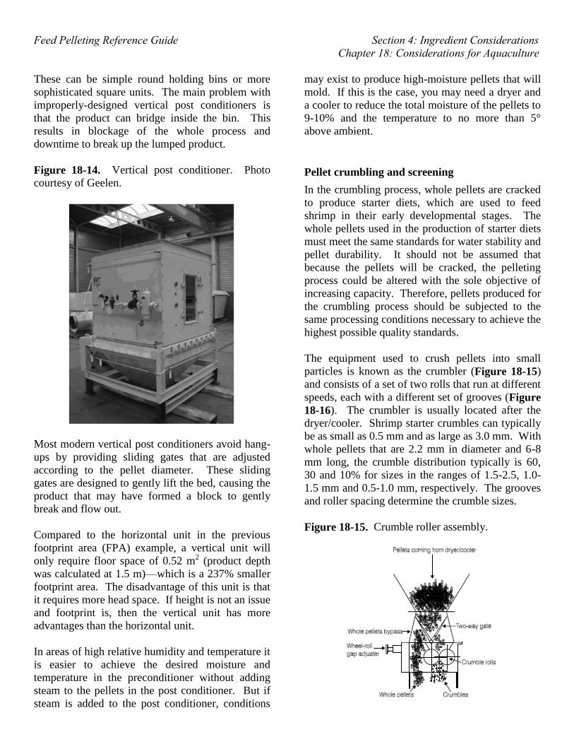
Vertical post-pellet conditioners
The vertical post-pellet cooker (Figure 18-14)
includes the option of further increasing the degree
of cooking by adding steam to the unit, and a steam
jacket to control the temperature of the unit. The
addition of steam, coupled with a long residence
time of up to 20 minutes, increases the total
moisture content from 17% (out of the die) to 22%.
Since starch gelatinization is a temperature-,
moisture- and time-dependant process, it is without
a doubt that such a system can further improve the
water stability of the pellets. At these high moisture
contents, however, the system also requires a dryer
to reduce the excess moisture that cannot be
achieved by evaporative cooling alone.
Feed Pelleting Reference Guide Section 4: Ingredient Considerations
Chapter 18: Considerations for Aquaculture
These can be simple round holding bins or more
sophisticated square units. The main problem with
improperly-designed vertical post conditioners is
that the product can bridge inside the bin. This
results in blockage of the whole process and
downtime to break up the lumped product.
Figure 18-14. Vertical post conditioner. Photo
courtesy of Geelen.
Most modern vertical post conditioners avoid hang-
ups by providing sliding gates that are adjusted
according to the pellet diameter. These sliding
gates are designed to gently lift the bed, causing the
product that may have formed a block to gently
break and flow out.
Compared to the horizontal unit in the previous
footprint area (FPA) example, a vertical unit will
only require floor space of 0.52 m2 (product depth
was calculated at 1.5 m)—which is a 237% smaller
footprint area. The disadvantage of this unit is that
it requires more head space. If height is not an issue
and footprint is, then the vertical unit has more
advantages than the horizontal unit.
In areas of high relative humidity and temperature it
is easier to achieve the desired moisture and
temperature in the preconditioner without adding
steam to the pellets in the post conditioner. But if
steam is added to the post conditioner, conditions
may exist to produce high-moisture pellets that will
mold. If this is the case, you may need a dryer and
a cooler to reduce the total moisture of the pellets to
9-10% and the temperature to no more than 5°
above ambient.
Pellet crumbling and screening
In the crumbling process, whole pellets are cracked
to produce starter diets, which are used to feed
shrimp in their early developmental stages. The
whole pellets used in the production of starter diets
must meet the same standards for water stability and
pellet durability. It should not be assumed that
because the pellets will be cracked, the pelleting
process could be altered with the sole objective of
increasing capacity. Therefore, pellets produced for
the crumbling process should be subjected to the
same processing conditions necessary to achieve the
highest possible quality standards.
The equipment used to crush pellets into small
particles is known as the crumbler (Figure 18-15)
and consists of a set of two rolls that run at different
speeds, each with a different set of grooves (Figure
18-16). The crumbler is usually located after the
dryer/cooler. Shrimp starter crumbles can typically
be as small as 0.5 mm and as large as 3.0 mm. With
whole pellets that are 2.2 mm in diameter and 6-8
mm long, the crumble distribution typically is 60,
30 and 10% for sizes in the ranges of 1.5-2.5, 1.0-
1.5 mm and 0.5-1.0 mm, respectively. The grooves
and roller spacing determine the crumble sizes.
Figure 18-15. Crumble roller assembly.

Feed Pelleting Reference Guide Section 4: Ingredient Considerations
Chapter 18: Considerations for Aquaculture
Figure 18-16. Crumble rollers rotate at different
speeds and have different corrugations.
An important objective of crumbling is to reduce
the amount of fines that are produced as the pellets
are crushed. More fines are generated when the
pellet diameter is too large in relation to the
particles that need to be produced. Larger diameter
pellets cannot properly enter through the nip angle
of the rollers, causing more fines as the rollers erode
them. The average amount of fines produced is
15%. These fines need to be removed, and, unlike
what is done with other farm animal feeds, they
should be sent to an ingredient bin and not to the
pellet mill. Fines that are returned to the pellet mill
can drastically reduce pellet quality. Some pellets
pass through the crumble rolls without breaking.
These pellets must be separated downstream and
redirected to the crumbler.
The screening process removes clumps produced in
the pelleting process. These clumps or larger pieces
are removed by the sifter as overs, and should be
separated and re-ground. When pelleting is
adequate, no more than 5% fines should be
produced. Exceeding this number may indicate
problems in the pelleting process or mechanical
handling that is too harsh.
The crumbling process produces different particle
sizes that need to be segregated into the different
fractions with a screener. The most common
equipment used in the separation of crumbles of
various sizes is the horizontal rotational screener
(Figure 18-17). These screeners are composed of
multiple stacked decks of sifting screens. These
units rotate and vibrate in three planes, making
them more efficient than common screener
separators. The rotational action is controlled by a
set of weights and a motor placed at the bottom of
the unit. Shifting the weights can increase or
decrease the dwell time by changing the direction of
flow on the screen.
Figure 18-17. Horizontal rotational screener used
to segregate crumbles.
Coating
Coaters are necessary to add those liquids that were
not included in the mix to avoid affecting the
processing and overall quality of the feed. One of
the most common ingredients added post-pelleting
or post extrusion is fish oil.
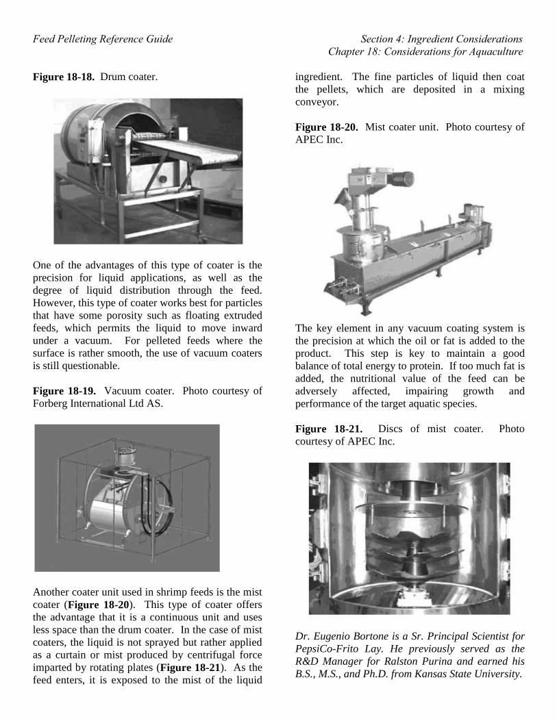
The most common method for adding fish oil is
through a drum coater (Figure 18-18). Drum
coaters are equipped with spray nozzles that apply
the liquid as the feed is gently tumbled. In the last
ten years, new coating systems have entered in the
aquatic feed market. One such piece of equipment
is the vacuum coater (Figure 18-19). This is
basically a batch unit that is filled with the pelleted
feed and then subjected to vacuum or 200 mbar of
absolute pressure. This allows for liquids to be
drawn into the pellet by capillary forces. Once the
liquid is applied and subjected to vacuum, the
pressure must be equalized back to atmospheric
pressure.
Feed Pelleting Reference Guide Section 4: Ingredient Considerations
Chapter 18: Considerations for Aquaculture
Figure 18-18. Drum coater.
One of the advantages of this type of coater is the
precision for liquid applications, as well as the
degree of liquid distribution through the feed.
However, this type of coater works best for particles
that have some porosity such as floating extruded
feeds, which permits the liquid to move inward
under a vacuum. For pelleted feeds where the
surface is rather smooth, the use of vacuum coaters
is still questionable.
Figure 18-19. Vacuum coater. Photo courtesy of
Forberg International Ltd AS.
Another coater unit used in shrimp feeds is the mist
coater (Figure 18-20). This type of coater offers
the advantage that it is a continuous unit and uses
less space than the drum coater. In the case of mist
coaters, the liquid is not sprayed but rather applied
as a curtain or mist produced by centrifugal force
imparted by rotating plates (Figure 18-21). As the
feed enters, it is exposed to the mist of the liquid
ingredient. The fine particles of liquid then coat
the pellets, which are deposited in a mixing
conveyor.
Figure 18-20. Mist coater unit. Photo courtesy of
APEC Inc.
The key element in any vacuum coating system is
the precision at which the oil or fat is added to the
product. This step is key to maintain a good
balance of total energy to protein. If too much fat is
added, the nutritional value of the feed can be
adversely affected, impairing growth and
performance of the target aquatic species.
Figure 18-21. Discs of mist coater. Photo
courtesy of APEC Inc.
Dr. Eugenio Bortone is a Sr. Principal Scientist for
PepsiCo-Frito Lay. He previously served as the
R&D Manager for Ralston Purina and earned his
B.S., M.S., and Ph.D. from Kansas State University.

Feed Pelleting Reference Guide Section 4: Ingredient Considerations
Chapter 18: Considerations for Aquaculture
This content was edited and reviewed by Dr.
Charles Stark, Jim and Carol Brown Associate
Professor of Feed Technology at Kansas State
University, Dr. Adam Fahrenholz, Assistant
Professor of Feed Milling at North Carolina State
University, and Dr. Cassandra Jones, Assistant
Professor of Feed Technology at Kansas State
University.