Embed Size (px)
Citation preview

The Optimum Choice for Performance, Convenience and Safety
Connections for Fluid Applications
»

Series 141 – 10 bar (145 PSI), Page 7
Series 414 – 35 bar (508 PSI), Page 13
Series 324 – 35 bar (508 PSI), Page 9
Series 326 – 70 bar (1015 PSI), Page 10
Series 411 – 35 bar (508 PSI), Page 11
Series 220/221, 225 – 35 bar (508 PSI), Page 8
Reliable, High-Flow Couplings for aAvailable in brass or stainless steel, valv e
We reserve the right to changes without further notification.2
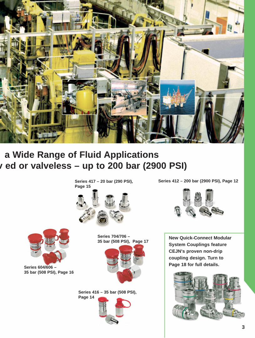
Series 412 – 200 bar (2900 PSI), Page 12
Series 416 – 35 bar (508 PSI), Page 14
Series 417 – 20 bar (290 PSI), Page 15
Series 604/606 –35 bar (508 PSI), Page 16
Series 704/706 – 35 bar (508 PSI), Page 17
New Quick-Connect Modular System Couplings feature CEJN's proven non-drip coupling design. Turn to Page 18 for full details.
a Wide Range of Fluid Applicationsv ed or valveless – up to 200 bar (2900 PSI)
3

4
CEJNYour Reliable Partner for High-Quality Fluid Couplings
The ability to quickly connect and discon -nect fluid lines is the fundamental role of quick couplings in fluid transfer applica-tions. Fluid couplings must also be leak free and withstand the media being transferred and the atmospheric and operating condi-tions to which they are subjected.
CEJN's leadership in the design, develop-ment, and manufacture of fluid couplings is evident in its more than 45 years of success-ful sales performance in numerous markets, each with its own specific demands.
This leadership is the result of our steadfast commitment to taking every step possible to ensure CEJN fluid couplings are synony-mous with high quality and superior perfor-mance characteristics.
CEJN's fluid coupling lineup includes over 14 different series of products in both valved and valveless designs for low- and medium-pressure applications.
Offering maximum working pressures up to 200 bar (2900 PSI), CEJN offers just the right coupling solution for virtually any fluid transfer application – from petrochemical, to pharmaceutical, to paint – in which lines
need to be connected and disconnected eas-ily, safely, and reliably.
Incorporating an innovative, aerodynamic valve design, all CEJN fluid couplings offer superior flow capacity with minimal pres-sure drop.
They are available in stainless steel, nickel-, chrome-, or non-plated brass, depending on the series, with seals in nitrile, viton®, or EPDM. Upon request, other coupling and seal material options are available to comply with specific performance objectives.
Because smooth fluid flow is a critical requirement in system operation, CEJN vig -orously tests each coupling it produces. All fluid couplings undergo extensive function-ality and quality testing to ensure defect-free performance where it is needed most – at the jobsite.
When you need smooth fluid flow and smooth equipment operation, call on CEJN – your Quick Connect Specialist and reliable partner for high-quality fluid couplings.
5

141 221 223 225 321 322 324 326 411 412 414 416 417 604 606 704 706
• • • • • • • • • • • • • • • • • • • • • • • •
• • • • • • • • • • • • • • • • • • • • • • • • • •
1 1 1 1 1 1 1 1 1 1 1 1 1 1 2 1 2 2 2 2 2 2 2 1 2 2 2 1 2 1 2 1 2 2 2 2 2 2 2 2 2 2 2 2 2 2 2 2 2 2 2 2 2
• • • • • • • • • • • • • • • • •
• • • • • • • • • • • • • • • • •
• • • • • • • • • • • •
• • • • • • • • • • • • • • • • • • • • • • • • • • • • • • • • • • 141 221 223 225 321 322 324 326 411 412 414 416 417 604 606 704 706
Series Flow l/min.0-5 5-10 10-20 20-30 30-50 50-75 75-100 100-150 150-200 200-250 250-300
FunctionSingle shut-off Double shut-off Straight through
SealingNitrile Viton® EP Kalrez® MaterialBrassStainless Steel AISI 316
StylePush-to-connect Two-hand operation
Dust CapsIncluded As accessory
Working Pressure8 10 20 35 70 200
Vacuum useYes No Series
Overview CEJN Fluid Couplings
1 = as standard, 2 = on request6

14110 141 1001 5.0 mm (3/16") NBR 52.0 12.0 -
10 141 1201 G 1/8" NBR 43.5 15.0 13
10 141 1251 G 1/8'' NBR 40.0 12.7 1110 141 1451 NPT 1/8" NBR 35.0 12.7 11
10 141 5000 3.0 mm (1/8'') - 32.0 7.0 -10 141 5001 5.0 mm (3/16'') - 40.5 7.0 -
10 141 5201 G 1/8'' - 30.0 13.9 12
10 141 5451 NPT 1/8" - 31.0 12.7 11
Nip
ples
(val
vele
ss)
Cou
plin
gs (v
alve
d) Hose connections
Female thread
Male thread
Hose connection
Female thread
Male thread
Part No. Connection Seals Length Dia. Hex.
Thread connections are listed according to ISO Standards. See Page 30 for additional information. All measurements are in mm. NBR=nitrile, FPM=Viton®. Check with an authorized CEJN distributor for availability and prices.
Series 14110 bar (145 PSI) – 3.5 l/min (0.8 GPM UK)
Technical Data Material: Chrome-plated brassFlow capacity at 4 bar pressure drop: 3.5 l/min (0.77 GPM UK)Max. working pressure: 10 bar (145 PSI) Min. burst pressure: 40 bar (580 PSI) Temperature range: -30°C to +100°C (-22°F to +212°F)Nominal fl ow diameter: 2.5 mm (3/32")Kv (Cv): 0.10 (0.12)
Information on CEJN's worldwide network of sales companies, agents, and distributors is available at www.cejn.com.
Series 141 miniature couplings are specially designed for dental and medical equipment applications. Among the smallest couplings available today, Series 141 features valved couplings and valveless nipples that are easily connected with one hand. Viton® and EPDM seals are available on request.
Pre
ssur
e dr
op, b
ar (P
SI)
Flow, liters/min. (GPM -UK)
7

22..10 220 1001 5.0 mm (3/16'') NBR 47.4 19.6 1710 220 1002 6.3 mm (1/4'') NBR 47.4 19.6 1710 220 1003 8.0 mm (5/16'') NBR 50.4 19.6 1710 220 1004 10.0 mm (3/8'') NBR 50.4 19.6 17
10 220 1151 R 1/8'' NBR 39.4 19.6 1710 220 1152 R 1/4'' NBR 42.9 19.6 1710 220 1154 R 3/8'' NBR 41.4 19.6 1710 220 1451 NPT 1/8" NBR 37.9 19.6 1710 220 1452 NPT 1/4" NBR 42.4 19.6 17
10 220 1201 G 1/8'' NBR 38.9 19.6 1710 220 1202 G 1/4'' NBR 42.9 19.6 1710 220 1204 G 3/8'' NBR 44.4 23.1 2010 220 1402 NPT 1/4" NBR 42.9 19.6 17
10 225 1202 G 1/4'' NBR 42.9 19.6 17
10 221 5009* 5.0 mm (3/16'') - 36.0 11.0 -10 221 5002 6.3 mm (1/4'') - 36.0 11.0 -
10 221 5152 R 1/4'' - 33.0 16.2 1410 221 5251 G 1/8'' - 26.5 12.7 1110 221 5452 NPT 1/4" - 33.0 16.2 14
10 221 5201 G 1/8'' - 26.5 15.0 1310 221 5202 G 1/4'' - 31.0 19.6 17
10 225 6202** G 1/4'' NBR 31.0 19.6 17
** Valved nipples in Series 225 can only be used with Series 225 couplings. N
ippl
es (v
alve
less
) C
oupl
ings
(val
ved) Hose connection
Male thread
Female thread
Hose connection(* nickel-plated)
Male thread
Female thread
Female thread(valved)
Part No. Connection Seals Length Dia. Hex.
Thread connections are listed according to ISO Standards. See Page 30 for additional information. All measurements are in mm. NBR=nitrile, FPM=Viton®. Check with an authorized CEJN distributor for availability and prices.
Series 220/221, 22535 bar (508 PSI) – 26 l/min (5.72 GPM UK)
Technical Data Material: Series 220 coupling: Nickel-plated brass Series 225 coupling: Chrome-plated brass Nipple: Chrome-plated brassFlow capacity at 4 bar pressure drop: Series 221 valveless nipple: 26 l/min (5.72 GPM UK) Series 225 valved nipple: 8 l/min (1.76 GPM UK) Max. working pressure: 35 bar (508 PSI) Min. burst pressure: 140 bar (2030 PSI) Temperature range NBR: -30°C to +100°C (-22°F to +212°F)Nominal fl ow diameter: Series 220 coupling: 5.0 mm (3/16") Series 225 coupling: 3.0 mm (1/8")Kv (Cv): Series 220: 0.79 (0.92) Series 225: 0.24 (0.28)
Requiring only one hand for operation, Series 220/221 and Series 225 couplings are suitable for a variety of fluid applica-tions, such as water inlet and return for injection molding lines. Series 220/221 features valved couplings and valveless nip-ples. Series 225 features both vavled couplings and valved nip-ples. Other sealing materials, such as viton® and EPDM, are available on request. Straight-through couplings are also avail-able on request.
Pre
ssur
e dr
op, b
ar (P
SI)
Flow, liters/min. (GPM -UK)
8

32410 324 1002 6.0 mm (1/4'') NBR 66.3 23.4 20
10 324 1003 8.0 mm (5/16'') NBR 68.3 23.4 20
10 324 1004 10.0 mm (3/8'') NBR 67.3 23.4 20
10 324 1005 13.0 mm (1/2'') NBR 66.3 23.4 20
10 324 1152 R 1/4'' NBR 59.3 23.4 20
10 324 1154 R 3/8'' NBR 58.3 23.4 20
10 324 1155 R 1/2'' NBR 51.8 25.4 22
10 324 1202 G 1/4'' NBR 56.3 23.4 20
10 324 1204 G 3/8'' NBR 56.3 25.4 22
10 324 1205 G 1/2'' NBR 60.3 28.9 25
10 324 1212 G 1/4'' FPM 56.3 23.4 20
10 324 1222 G 1/4'' EPDM 56.3 23.4 20
10 324 1402 NPT 1/4'' NBR 56.3 23.4 20
10 324 6202 G 1/4'' NBR 52.1 23.1 20
10 324 6212 G 1/4'' FPM 52.1 23.1 20
10 324 6222 G 1/4'' EPDM 52.1 23.1 20
10 324 6402 NPT 1/4'' NBR 52.1 23.1 20
Series 32435 bar (508 PSI) - 42 l/min (9.2 GPM UK)
Technical Data Material: Nickle-plated brassFlow capacity at 4 bar pressure drop: Series 324 nipple: 42 l/min (9.2 GPM UK) Series 321 nipple: 53 l/min (11.6 GPM UK)Max. working pressure: 35 bar (508 PSI) Min. burst pressure: 140 bar (2030 PSI) Temperature range NBR: -30°C to +100°C (-22°F to +212°F)Nominal fl ow diameter: 6.2 mm (1/4")Kv (Cv): 324 nipple 1.26 (1.46) 321 nipple 1.59 (1.85)
N
ippl
es (v
alve
d)
Cou
plin
gs (v
alve
d) Hose connection
Male thread
Female thread
Female thread
Part No. Connection Seals Length Dia. Hex.
Thread connections are listed according to ISO Standards. See Page 30 for additional information. All measurements are in mm. NBR=nitrile, FPM=Viton®. Check with an authorized CEJN distributor for availability and prices.
Series 324 offers a two-way shutoff and is connectable with the valveless nipple in Series 321. Designed with small external dimensions, it is suitable for a variety of fluid applications, such as water inlet and return for injection molding lines. Only one hand is required to connect this original CEJN product offering. Dust caps are included. Other sealing materials and connec-tions are available on request.
Pre
ssur
e dr
op, b
ar (P
SI)
Flow, liters/min. (GPM -UK)
9
32610 326 1202 G 1/4'' NBR 51.3 24.3 21
10 326 1204 G 3/8'' * NBR 54.8 25.4 22
10 326 1212 G 1/4'' FPM 51.3 24.3 21
10 326 1214 G 3/8'' * FPM 54.8 25.4 22
10 326 6202 G 1/4'' NBR 52.1 22.0 19
10 326 6204 G 3/8'' NBR 54.1 25.4 22
10 326 6212 G 1/4'' FPM 52.1 22.0 19
10 326 6214 G 3/8'' FPM 54.1 25.4 22
10 326 5232 G 1/4'' - 37.5 19.6 17
N
ippl
es
Cou
plin
gs (v
alve
d) Female thread
(* 9 mm)
Female thread
(valved)
Female thread
(valveless)
Part No. Connection Seals Length Dia. Hex.
Thread connections are listed according to ISO Standards. See Page 30 for additional information. All measurements are in mm. NBR=nitrile, FPM=Viton®. Check with an authorized CEJN distributor for availability and prices.
Series 32670 bar (1015 PSI) - 18 l/min (3.9 GPM UK)
Technical Data Material: Stainless steel, AISI 316 Flow capacity at 4 bar pressure drop: Valved nipple: 18 l/min (3.96 GPM UK) Valveless nipple: 28 l/min (6.16 GPM UK)Max. working pressure: 70 bar (1015 PSI) Min. burst pressure: 280 bar (4060 PSI) Temperature range FPM: -15°C to +100°C (+5°F to +212°F)Nominal fl ow diameter: 6.2 mm (1/4")Kv (Cv): valved 0.54 (0.63) valveless 0.84 (0.98)
CEJN uses only the finest raw materials to produceits high-quality products.
Compatible with aggressive medias, Series 326 stands up to food, offshore, and steam applications. One- and two-way shut-off styles are included in the series that requires only one hand for operation. Dust caps are included as standard. EPDM seals are available on request.
Pre
ssur
e dr
op, b
ar (P
SI)
Flow, liters/min. (GPM -UK)
10

41110 411 1003 8.0 mm (5/16") NBR 73.8 27.7 24
10 411 1004 10.0 mm (3/8") NBR 72.8 27.7 24
10 411 1005 13.0 mm (1/2") NBR 71.3 27.7 24
10 411 1006 16.0 mm (5/8") NBR 72.3 27.7 24
10 411 1007 19.0 mm (3/4") NBR 70.3 27.7 24
10 411 1066 11x16 mm NBR 78.6 27.7 24
10 411 1154 R 3/8" NBR 63.8 27.7 24
10 411 1155 R 1/2" NBR 66.3 27.7 24
10 411 1157 R 3/4" NBR 59.8 31.2 27
10 411 1204 G 3/8" NBR 58.3 27.7 24
10 411 1205 G 1/2" NBR 63.3 28.9 25
10 411 1207 G 3/4" NBR 60.3 37.0 32
10 411 5004 10.0 mm (3/8") - 46.5 17.0 -
10 411 5005 13.0 mm (1/2") - 46.0 17.0 -
10 411 5006 16.0 mm (5/8") - 48.5 21.0 -
10 411 5007 19.0 mm (3/4") - 49.0 25.0 -
10 411 5066 11x16 mm - 540.0 27.7 24
10 411 5255 G 1/2" - 37.0 25.4 22
10 411 5257 G 3/4" - 39.5 31.2 27
10 411 5204 G 3/8" - 34.5 24.2 21
10 411 5205 G 1/2" - 34.5 27.7 24
10 411 5207 G 3/4" - 35.0 34.6 30
Series 411 35 bar (508 PSI) - 156 l/min (34.3 GPM UK)
Technical Data Material: Coupling- Nickle-plated brass Nipple- Chrome-plated brassFlow capacity at 4 bar pressure drop: 156 l/min (34.32 GPM UK)Max. working pressure: 35 bar (508 PSI) Min. burst pressure: 140 bar (2030 PSI) Temperature range NBR: -30°C to +100°C (-22°F to +212°F)Nominal fl ow diameter: 10.4 mm (13/32")Kv (Cv): 4.68 (5.44)
N
ippl
es (v
alve
less
) C
oupl
ings
(val
ved) Hose connection
Stream-Line Connection
Male thread
Female thread
Hose connection
Stream-Line Connection
Male thread
Female thread
Part No. Connection Seals Length Dia. Hex.
Thread connections are listed according to ISO Standards. See Page 30 for additional information. All measurements are in mm. NBR=nitril,FPM=Viton®. Check with an authorized CEJN distributor for availability and prices.
Series 411 features valved couplings and valveless nipples. Requiring only one hand for operation, the series is suitable for a variety of fluid applications, such as water inlet and return for injection molding lines.
Pre
ssur
e dr
op, b
ar (P
SI)
Flow, liters/min. (GPM -UK)
11

41210 412 0255 * G 1/2'' NBR 50.7 27.7 24
10 412 0455 NPT 1/2" NBR 65.3 27.7 24
10 412 1205 G 1/2'' NBR 63.3 28.9 25
10 412 0205 G 1/2'' NBR 63.3 28.9 25
10 412 0405 NPT 1/2'' NBR 63.3 28.9 25
10 412 5265 * G 1/2'' - 42.3 25.4 22
10 412 5205 G 1/2'' - 44.0 31.2 27
10 410 5154 R 3/8'' - 42.5 19.6 17
10 410 5155 R 1/2'' - 48.0 25.4 22
10 410 5204 G 3/8'' - 39.0 23.1 20
10 410 5205 G 1/2'' - 44.0 31.2 27
N
ippl
es (v
alve
less
) C
oupl
ings Male thread
(valveless * with 60° sealing cone)
Female thread(valved)
Female thread(valveless)
Male thread(Steel – hardened and chemical nickel-plated * with 60° sealing cone)
Female thread(Steel – hardened and chemical nickel-plated )
Male thread(Steel – hardened and zinc-plated)
Female thread(Steel – hardened and zinc-plated)
Part No. Connection Seals Length Dia. Hex.
Thread connections are listed according to ISO Standards. See Page 30 for additional information. All measurements are in mm. NBR = nitrile, FPM = Viton®. Check with an authorized CEJN distributor for availability and prices.
Series 412 200 bar (2900 PSI) - 167 l/min (36.7 GPM UK)
Technical Data Material: Coupling–Nickle-plated brass/steel Nipple–Hardened steel, chemical nickel-plated/zinc-plated Flow capacity at 4 bar pressure drop: 167 l/min (36.74 GPM UK)Max. working pressure: 200 bar (2900 PSI) Min. burst pressure: 600 bar (8700 PSI) Temperature range NBR: -30°C to +100°C (-22°F to +212°F)Nominal fl ow diameter: 10.4 mm (13/32")Kv (Cv): 5.01 (5.83)
The 200 bar working pressure of Series 412 makes this prod-uct line suitable for high-pressure water applications and high-pressure cleaning. Included in the series are valved and valve-less couplings and valveless nipples. Only one hand is required for operation. Other sealing materials are available on request.
Pre
ssur
e dr
op, b
ar (P
SI)
Flow, liters/min. (GPM -UK)
12

41410 414 1004 10.0 mm (3/8'') NBR 72.8 27.7 24
10 414 1005 13.0 mm (1/2'') NBR 71.3 27.7 24
10 414 1006 16.0 mm (5/8'') NBR 71.3 27.7 24
10 414 1007 19.0 mm (3/4'') NBR 70.3 27.7 24
10 414 1154 R 3/8'' NBR 63.8 27.7 24
10 414 1155 R 1/2'' NBR 66.3 27.7 24
10 414 1157 R 3/4'' NBR 59.8 31.2 27
10 414 1204 G 3/8'' NBR 58.3 27.7 24
10 414 1205 G 1/2'' NBR 63.3 28.9 25
10 414 1207 G 3/4'' NBR 60.3 37.0 32
10 414 1405 NPT 1/2'' NBR 63.3 28.9 25
10 414 6205 G 1/2'' NBR 59.4 31.2 27
10 414 6405 NPT 1/2'' NBR 59.4 31.2 27
Series 41435 bar (508 PSI) - 71 l/min (15.6 GPM UK )
Technical Data Material: Chrome-plated brassFlow capacity at 4 bar pressure drop: Series 414 nipple: 71 l/min (15.6 GPM UK) Series 411 nipple: 104 l/min (22.9 GPM UK)Max. working pressure: 35 bar (508 PSI) Min. burst pressure: 140 bar (2030 PSI) Temperature range NBR: -30°C to +100°C (-22°F to +212°F)Nominal fl ow diameter: 8.9 mm (11/32")Kv (Cv): double valved 2.13 (2.48) 411 nipple 3.12 (3.63)
N
ippl
es (v
alve
d)
Cou
plin
gs (v
alve
d) Hose connection
Male thread
Female thread
Female thread
Part No. Connection Seals Length Dia. Hex.
Thread connections are listed according to ISO Standards. See Page 30 for additional information. All measurements are in mm. NBR = nitrile, FPM = Viton®. Check with an authorized CEJN distributor for availability and prices.
Series 414 includes a two-way shutoff and is connectable with Series 411 valveless nipples. Requiring only one hand for operation, Series 414 couplings are suitable for a variety of fluid applications, such as water inlet and return for injection molding lines. Dust caps are included as standard. Viton® and EPDM sealings are available on request.
Pre
ssur
e dr
op, b
ar (P
SI)
Flow, liters/min. (GPM -UK)
13

41610 416 1205 G 1/2'' NBR 63.3 31.2 2710 416 1215 G 1/2'' FPM 63.3 31.2 27
10 416 6205 G 1/2'' NBR 60.5 31.2 2710 416 6215 G 1/2'' FPM 60.5 31.2 27
10 416 5205 G 1/2'' - 45.0 31.2 27
N
ippl
es
Cou
plin
gs
Female thread(valved)
Female thread(valved)
Female thread(valveless)
Part No. Connection Seals Length Dia. Hex.
Thread connections are listed according to ISO Standards. See Page 30 for additional information. All measurements are in mm. NBR = nitril, FPM = Viton®. Check with an authorized CEJN distributor for availability and prices.
Series 416 35 bar (508 PSI)
Technical Data Material: Stainless steel, AISI 316Flow capacity at 4 bar pressure drop: Valved nipple: 45 l/min (9.9 GPM UK) Valveless nipple: 85 l/min (18.7 GPM UK) Max. working pressure: 35 bar (508 PSI) Min. burst pressure: 140 bar (2030 PSI) Temperature range FPM: -15°C to +205°C (+5°F to +401°F)Nominal fl ow diameter: 8.9 mm (11/32")Kv (Cv): 1.35 (1.57) valved, 2.55 (2.96) valveless nipple
CEJN's wide range of fl uid products includes water hose. For information on hose products, order CEJN's comprehensive hose catalog at www.cejn.com, or contact your nearest CEJN offi ce or distributor.
Compatible with aggressive medias, Series 416 stands up to food, offshore, and steam applications. One- and two-way shutoff styles are included in the series that requires only one hand for operation. Dust caps are included as standard. EPDM and Kalrez® seals are available on request.
Pre
ssur
e dr
op, b
ar (P
SI)
Flow, liters/min. (GPM -UK)
14

41710 417 0005 13.0 mm (1/2") NBR 45.0 24.0 -
10 417 0006 16.0 mm (5/8") NBR 46.5 24.0 -
10 417 0007 19.0 mm (3/4") NBR 47.0 24.0 -
10 417 0255 G 1/2" NBR 30.0 24.0 -
10 417 0257 G 3/4" NBR 29.0 24.0 -
10 417 0205 G 1/2" NBR 32.5 27.7 24
10 417 0207 G 3/4" NBR 34.0 32.0 30
10 411 5004 10.0 mm (3/8") - 46.5 17.0 -
10 411 5005 13.0 mm (1/2") - 46.0 17.0 -
10 411 5006 16.0 mm (5/8") - 48.5 21.0 -
10 411 5007 19.0 mm (3/4") - 49.0 25.0 -
10 411 5255 G 1/2" - 37.0 25.4 22
10 411 5257 G 3/4" - 39.5 31.2 27
10 411 5204 G 3/8" - 34.5 24.3 21
10 411 5205 G 1/2" - 34.5 27.7 24
10 411 5207 G 3/4" - 35.0 34.6 30
10 411 7005 13.0 mm (1/2") EPDM 64.0 23.0 -
10 411 7255 G 1/2" EPDM 37.0 25.4 22
Series 417 20 bar (290 PSI) - 226 l/min (49.7 GPM UK)
Technical Data Material: Chrome-plated brassFlow capacity at 4 bar pressure drop: 226 l/min (49.72 GPM UK)Max. working pressure: 20 bar (290 PSI) Min. burst pressure: 80 bar (1160 PSI) Temperature range: -30°C to +100°C (-22°F to +212°F)Nominal fl ow diameter: 10.5 mm (13/32")Kv (Cv): 6.78 (7.88)
N
ippl
es (v
alve
d)
Nip
ples
(val
vele
ss)
Cou
plin
gs (v
alve
less
) Hose connection
Male thread
Female thread
Hose connection
Male thread
Female thread
Hose connection
Male thread
Part No. Connection Seals Length Dia. Hex.
Thread connections are listed according to ISO Standards. See Page 30 for additional information. All measurements are in mm. NBR = nitril, FPM = Viton®. Check with an authorized CEJN distributor for availability and prices.
The straight-through, valveless design of Series 417 couplings makes them ideal for garden and other low-pressure applica-tions in which there is no need for valved-style couplings. Two hands are needed to connect Series 417 couplings, which are connectable to Series 411 nippels.
Pre
ssur
e dr
op, b
ar (P
SI)
Flow, liters/min. (GPM -UK)
15

60..10 604 1201 G 3/4'' NBR 83.0 47.3 4110 604 1211 G 3/4'' FPM 83.0 47.3 4110 604 1401 NPT 3/4'' NBR 83.0 47.3 4110 604 1411 NPT 3/4'' FPM 83.0 47.3 41
10 606 1211 G 3/4'' FPM 83.0 47.3 41
10 604 6201 G 3/4'' NBR 81.5 41.6 3610 604 6211 G 3/4'' FPM 81.5 41.6 3610 604 6401 NPT 3/4'' NBR 81.5 41.6 3610 604 6411 NPT 3/4'' FPM 81.5 41.6 36
10 606 6211 G 3/4'' FPM 81.5 41.6 36
10 604 5201 G 3/4'' - 81.5 41.6 3610 604 5401 NPT 3/4'' - 81.5 41.6 36
10 606 5201 G 3/4'' - 81.5 41.6 3610 606 5401 NPT 3/4'' - 81.5 41.6 36
N
ippl
es
Cou
plin
gs Female thread(valved)
Female thread(valved)
Female thread(valveless)
Part No. Connection Seals Length Dia. Hex.
Thread connections are listed according to ISO Standards. See Page 30 for additional information. All measurements are in mm. NBR=nitrile, FPM=Viton®. Check with an authorized CEJN distributor for availability and prices.
One- and two-way shutoff styles are included in Series 604 and Series 606 couplings that require only one hand for operation. Series 604 is suitable for a variety of fluid applications, such as water inlet and return. Series 606 stands up to food, offshore, and steam applications. Dust caps are included as standard.
Series 604, 60635 bar (508 PSI)
Technical Data Series 604Material: Chrome-plated brassFlow capacity at 4 bar pressure drop: valved nipple: 140 l/min (30.8 GPM UK) valveless nipple: 210 l/min (46.2 GPM UK)Max. working pressure: 35 bar (508 PSI) Min. burst pressure: 140 bar (2030 PSI) Temperature range NBR: -30°C to +100°C (-22°F to +212°F)Nominal fl ow diameter: 14.5 mm (9/16")Kv (Cv): valved 4.20 (4.88) valveless nipple 6.30 (7.33)
Pre
ssur
e dr
op, b
ar (P
SI)
Flow, liters/min. (GPM -UK)
Technical Data Series 606 Material: Stainless steel, AISI 316 Flow capacity at 4 bar pressure drop: valved nipple: 134 l/min (29.4 GPM UK) valveless nipple: 207 l/min (45.5 GPM UK)Max. working pressure: 35 bar (508 PSI) Min. burst pressure: 140 bar (2030 PSI) Temperature range: FPM -15°C to +205°C (+5°F to +401°F)Nominal fl ow diameter: 14.5 mm (9/16")Kv (Cv): valved 4.02 (4.67) valveless nipple 6.21 (7.22)
16

70..10 704 1203 G 1'' NBR 94.0 53.1 4610 704 1213 G 1'' FPM 94.0 53.1 4610 704 1403 NPT 1'' NBR 94.0 53.1 4610 704 1413 NPT 1'' FPM 94.0 53.1 46
10 706 1213 G 1'' FPM 94.0 53.0 46
10 704 6203 G 1'' NBR 91.5 53.1 4610 704 6213 G 1'' FPM 91.5 53.1 4610 704 6403 NPT 1'' NBR 91.5 53.1 4610 704 6413 NPT 1'' FPM 91.5 53.1 46
10 706 6213 G 1'' FPM 91.5 53.1 46
10 704 5203 G 1'' - 91.5 53.1 46
10 706 5203 G 1'' - 91.5 53.1 46
Requiring only one hand for operation, Series 704 and Series 706 couplings feature a two-way shutoff. A valveless nipple style is available upon request. Series 704 is suitable for water inlet and return for injection molding lines. Series 706 stands up to food, offshore, and steam applications. Dust caps are included as standard.
Series 704, 70635 bar (508 PSI)
Part No. Connection Seals Length Dia. Hex.
Thread connections are listed according to ISO Standards. See Page 30 for additional information. All measurements are in mm. NBR=nitrile, FPM=Viton®. Check with an authorized CEJN distributor for availability and prices.
N
ippl
es
Cou
plin
gs Female thread(valved)
Female thread(valved)
Female thread(valveless)
Technical Data Series 704 Material: Chrome-plated brassFlow capacity at 4 bar pressure drop: 271 l/min (59.62 GPM UK)Max. working pressure: 35 bar (508 PSI) Min. burst pressure: 140 bar (2030 PSI) Temperature range NBR: -30°C to +100°C (-22°F to +212°F)Nominal fl ow diameter: 19.0 mm (3/4")Kv (Cv): 8.13 (9.45)
Pre
ssur
e dr
op, b
ar (P
SI)
Flow, liters/min. (GPM -UK)
Technical Data Series 706 Material: Stainless steel, AISI 316 Flow capacity at 4 bar pressure drop: 227 l/min (49.94 GPM UK)Max. working pressure: 35 bar (508 PSI) Min. burst pressure: 140 bar (2030 PSI) Temperature range: FPM -15°C to +205°C (+5°F to +401°F)Nominal fl ow diameter: 19.0 mm (3/4")Kv (Cv): 6.81 (7.20)
17

267 277 467 477 567 577 667 677 767 777
X X X X XX X X X X
DN 4 DN 6 DN 9 DN 14 DN 19
17 l/min ( 3.7 GPM uk) 36 l/min (7.9 GPM uk) 76 l/min (16.7 GPM uk) 168 l/min (37.0 GPM uk) 306 l/min (67.3 GPM uk)17 l/min (3.7 GPM uk) 36 l/min (7.9 GPM uk) 78 l/min (17.2 GPM uk) 193 l/min (42.5 GPM uk) 334 l/min (73.5 GPM uk)32 l/min (7.0 GPM uk) 62 l/min (13.6 GPM uk) 187 l/min (41.1 GPM uk) 413 l/min (90.9 GPM uk) 803 l/min (176.7 GPM uk)
20 bar (290 PSI) 20 bar (290 PSI) 20 bar (290 PSI) 20 bar (290 PSI) 20 bar (290 PSI)80 bar (1160 PSI) 80 bar (1160 PSI) 80 bar (1160 PSI) 80 bar (1160 PSI) 80 bar (1160 PSI)
4 mm (5/32") 6 mm (1/4") 9 mm (11/32") 14 mm (9/16") 19 mm (3/4")0.51 (0.59) 1.08 (1.26) 2.28 (2.65) 5.04 (5.86) 9.18 (10.67)
-15ºC – +100ºC (+5ºF – +212ºF)-5ºC – +205ºC (+23ºF – +401ºF) -20ºC – +150ºC (-4ºF – +302ºF)-5°C – +315ºC (+23ºF – +600ºF)
Technical Data
Flow capacity is measured at 4 bar pressure drop for all three versions. For more information about seal recommendations, conversion tables, maintenence advice, and other fl uid products from CEJN, see the general CEJN Fluid Catalog, available at www.cejn.com or from your nearest authorized CEJN distributor. CEJN reserves the right to make changes without further notifi cation. This right is applicable to all information in this brochure.
The Right Product for Each and Every ApplicationWith unlimited combination possibilities, CEJN’s non-drip modular couplings are adaptable to most applications and system requirements. This means customers will no longer be burdened with searching out application-worthy couplings. CEJN has already done the work for them by incorporat-ing just what customers want and need most in a modular coupling line – versatility and virtually spillage-free perfor-mance.
The part number listing on Page 6 includes basic coupling and nipple combinations and reflects only a small portion of combinations that are possible by varying seals, threads, or other product features.
The fluid series includes both valved and valveless couplings and nipples, which further extend application possibilities. Valved styles are one-hand operated and are the most com-monly used version in fluid system applications. Due to their construction, the valveless couplings require two hands for connection/disconnection and are useful in those applications in which fluid loss upon disconnection may not be critical.
Three configurations are available in the extensive standard range:• Single shutoff (must utilize a coupling and valveless nipple)• Double shutoff • Straight through
The series is compatible with working pressures up to 20 bar (290 PSI) and temperatures up to 315° C (600° F), making it suitable for a variety of low-pressure fluid applications in which lines need to be connected and disconnected easily, safely, and without spillage. Sizes available include body sizes from 1/4-inch to 1 inch.
CEJN modular couplings are available in nickel-plated brass with nitrile seals and AISI 316 stainless steel with Viton® seals. EPDM and Kalrez® seals are available upon request to comply with specific performance objectives.
With or without valve
Body SizeSeriesMaterials Nickel-plated brass Stainless steel AISI 316Flow Capacity Double shutoff Single shutoff Straight throughMax. Working PressureMin. Burst PressureNominal Flow DiameterKv (Cv) (Double shutoff)Temperature Range NBR (Nitrile rubber) FPM (Viton®) Please note – Colored rings can only withstand heat up to +125ºC (+257ºF)
EPDM Kalrez® Please note – Colored rings can only withstand heat up to +125ºC (+257ºF)
18

1/4" 10 267 0200 10 267 0400 43.5 59.2 23 191/4" 10 267 1200 10 267 1400 43.5 59.2 23 191/4" 10 267 5200 10 267 5400 48.5 48.5 20 191/4" 10 267 6200 10 267 6400 48.5 48.5 20 19
3/8" 10 467 0200 10 467 0400 45.0 61.2 29 223/8" 10 467 1200 10 467 1400 45.0 61.2 29 223/8" 10 467 5200 10 467 5400 52.0 50.5 24 223/8" 10 467 6200 10 467 6400 52.0 50.5 24 22
1/2" 10 567 0200 10 567 0400 52.5 68.2 34 271/2" 10 567 1200 10 567 1400 52.5 68.2 34 271/2" 10 567 5200 10 567 5400 56.5 55.0 29 271/2" 10 567 6200 10 567 6400 56.5 55.0 29 27
3/4" 10 667 0200 10 667 0400 74.2 71.7 41 363/4" 10 667 1200 10 667 1400 74.2 71.7 41 363/4" 10 667 5200 10 667 5400 66.0 63.0 36 343/4" 10 667 6200 10 667 6400 66.0 63.0 36 34
1" 10 767 0200 10 767 0400 82.0 79.0 52 461" 10 767 1200 10 767 1400 82.0 79.0 52 461" 10 767 5200 10 767 5400 67.5 64.5 44 411" 10 767 6200 10 767 6400 67.5 64.5 44 41
1/4" 10 277 0210 10 277 0410 43.5 59.2 23 191/4" 10 277 1210 10 277 1410 43.5 59.2 23 191/4" 10 277 5210 10 277 5410 48.5 48.5 20 191/4" 10 277 6210 10 277 6410 48.5 48.5 20 19
3/8" 10 477 0210 10 477 0410 45.0 61.2 29 223/8" 10 477 1210 10 477 1410 45.0 61.2 29 223/8" 10 477 5210 10 477 5410 52.0 50.5 24 223/8" 10 477 6210 10 477 6410 52.0 50.5 24 22
1/2" 10 577 0210 10 577 0410 52.5 68.2 34 271/2" 10 577 1210 10 577 1410 52.5 68.2 34 271/2" 10 577 5210 10 577 5410 56.5 55.0 29 271/2" 10 577 6210 10 577 6410 56.5 55.0 29 27
3/4" 10 677 0210 10 677 0410 74.2 71.7 41 363/4" 10 677 1210 10 677 1410 74.2 71.7 41 363/4" 10 677 5210 10 677 5410 66.0 63.0 39 363/4" 10 677 6210 10 677 6410 66.0 63.0 39 36
1" 10 777 0210 10 777 0410 82.0 79.0 52 461" 10 777 1210 10 777 1410 82.0 79.0 52 461" 10 777 5210 10 777 5410 67.5 64.5 44 411" 10 777 6210 10 777 6410 67.5 64.5 44 41
Standard Range Brass (NBR Seal) Stainless Steel (FPM Seal)
Ser
ies
267 Description Connection Part No. G-thread Part No. NPT-thread Length (G) Length (NPT) Diameter Hexagon
Coupling, valveless FemaleCoupling, valved FemaleNipple, valveless FemaleNipple, valved Female
Ser
ies
467 Description Connection Part No. G-thread Part No. NPT-thread Length (G) Length (NPT) Diameter Hexagon
Coupling, valveless FemaleCoupling, valved FemaleNipple, valveless FemaleNipple, valved Female
Ser
ies
567 Description Connection Part No. G-thread Part No. NPT-thread Length (G) Length (NPT) Diameter Hexagon
Coupling, valveless FemaleCoupling, valved FemaleNipple, valveless FemaleNipple, valved Female
Ser
ies
667 Description Connection Part No. G-thread Part No. NPT-thread Length (G) Length (NPT) Diameter Hexagon
Coupling, valveless FemaleCoupling, valved FemaleNipple, valveless FemaleNipple, valved Female
Ser
ies
767 Description Connection Part No. G-thread Part No. NPT-thread Length (G) Length (NPT) Diameter Hexagon
Coupling, valveless FemaleCoupling, valved FemaleNipple, valveless FemaleNipple, valved Female
Ser
ies
277 Description Connection Part No. G-thread Part No. NPT-thread Length (G) Length (NPT) Diameter Hexagon
Coupling, valveless FemaleCoupling, valved FemaleNipple, valveless FemaleNipple, valved Female
Ser
ies
477 Description Connection Part No. G-thread Part No. NPT-thread Length (G) Length (NPT) Diameter Hexagon
Coupling, valveless FemaleCoupling, valved FemaleNipple, valveless FemaleNipple, valved Female
Ser
ies
577 Description Connection Part No. G-thread Part No. NPT-thread Length (G) Length (NPT) Diameter Hexagon
Coupling, valveless FemaleCoupling, valved FemaleNipple, valveless FemaleNipple, valved Female
Ser
ies
677 Description Connection Part No. G-thread Part No. NPT-thread Length (G) Length (NPT) Diameter Hexagon
Coupling, valveless FemaleCoupling, valved FemaleNipple, valveless FemaleNipple, valved Female
Ser
ies
777 Description Connection Part No. G-thread Part No. NPT-thread Length (G) Length (NPT) Diameter Hexagon
Coupling, valveless FemaleCoupling, valved FemaleNipple, valveless FemaleNipple, valved Female
All thread connections are listed according to ISO Standards. All measurements are in mm. Check with an authorized CEJN distributor for availability and prices. 19

19 958 1240 8.0 x 12.0 10 / 145 100
19 958 1640 11.0 x 16.0 10 / 145 100
8.0 x 12.0 10 321 1062 10 321 5062 - -
11.0 x 16.0 10 321 1066 10 321 5066 10 411 1066 10 411 5066
8.0 x 12.0 1/4" 19 958 1262 19 958 1212 19 958 1292 19 958 1242
8.0 x 12.0 3/8" 19 958 1264 19 958 1214 19 958 1294 19 958 1244
11.0 x 16.0 1/2" 19 958 1665 19 958 1615 19 958 1695 19 958 1645
Thread connections are listed according to ISO Standards. See Page 30 for additional information. Check with an authorized CEJN distributor for availability and prices.
Pre
ssur
e, B
ar (P
SI)
Temperature in ºC (ºF)
Part No. Size ID x OD (mm) Working Pressue (bar/PSI) Total Length per Roll (m)
Wat
erStream-Line Straight Braided HoseFor Water
CEJN Stream-Line straight polyurethane hose, designed for working pressures up to 10 bar, is suitable for both water and compressed air applications. When compressed air lines are in prolonged contact with water, use this hose instead of an air hose to ensure proper function.
Flexible and long lasting, it features two layers of blue ether-based PUR and a reinforced middle layer of polyester fiber. This construction gives the hose an extended temperature range of -30 ºC to +60 ºC. Additional sizes are available upon request.
Meter markings are indicated on the hose to make cutting and assembly easy.
Hos
e Fi
tting
s
Hose ID x OD Adapter R Thread R Thread NPT Thread NPT Thread Dim. mm Male Thread with swivel without swivel with swivel without swivel
Stream-Line Hose AdaptersFor Series 321, Series 411 and with Standard Thread
Other CEJN Products Suitable for Fluid Applications Other CEJN coupling series may be suitable for fluid applications, depending on working pressure and media. In addition, CEJN's range of breathing air couplings also includes the following brass styles:• Series 221 – Couplings with a "large-grip" locking sleeve that is interchangeable with Standard 221 nipples• Series 341, 344 – Single shutoff couplings and nipples with an integrated safety feature that protects against unintentional disconnection • Series 345, 347 – Double shutoff couplings and nipples with an integrated safety feature that protects against unintentional disconnection • Series 346 – Single or double shutoff couplings and nipples in AISI 316 stainless material with an integrated safety feature that protects against
unintentional disconnection. CEJN also offers stainless/chemical nickel-plated versions of Series 116 couplings in its high-pressure hydraulics range for extremely high pressures up to 1500 bar.
Brochures available on other CEJN products are listed on Page 31.
Coupling 321 Nipple 321 Coupling 411 Nipple 411
20
19 900 3211 G 1/4” - G 1/8” 19 900 3221 G 3/8” - G 1/8” 19 900 3222 G 3/8” - G 1/4” 19 900 3232 G 1/2” - G 1/4” 19 900 3234 G 1/2” - G 3/8” 19 900 3244 G 3/4” - G 3/8” 19 900 3245 G 3/4” - G 1/2” 19 900 4302 G 1/4” 19 900 4304 G 3/8” 19 900 4305 G 1/2” 19 900 4307 G 3/4” 19 900 5302 G 1/4” 19 900 5304 G 3/8” 19 900 5305 G 1/2” 19 900 5309 G 1” 19 900 5322 G 1/4” 19 900 5324 G 3/8” 19 900 5325 G 1/2” 19 900 5332 G 1/4” 19 900 5334 G 3/8” 19 900 5335 G 1/2” 19 900 5361 G 1/8” 19 900 5362 G 1/4” 19 900 5364 G 3/8” 19 900 5365 G 1/2” 19 900 5371 G 1/8” 19 900 5372 G 1/4” 19 900 5374 G 3/8” 19 900 5375 G 1/2” 19 900 5379 G 1” 19 900 5382 G 1/4” 19 900 5384 G 3/8” 19 900 5385 G 1/2” 19 900 5916 G 1/4” 19 900 5912 G 3/8” 19 900 5902 G 1/2” 19 900 5920 G 1/4” 19 900 5921 G 3/8” 19 900 5925 G 1/2” 19 900 5906 G 1/8” 19 900 5905 G 1/4” 19 900 5904 G 3/8” 19 900 5903 G 1/2” 19 900 5932 G 1/4” 19 900 5934 G 3/8” 19 900 5935 G 1/2”
19 900 0211 R 1/8” - 3/16"19 900 0212 R 1/8” - 1/4”19 900 0221 R 1/4” - 3/16”19 900 0222 R 1/4” - 1/4”19 900 0223 R 1/4” - 5/16”19 900 0224 R 1/4” - 3/8”19 900 0225 R 1/4” - 1/2”19 900 0232 R 3/8” - 1/4”19 900 0233 R 3/8” - 5/16”19 900 0234 R 3/8” - 3/8”19 900 0235 R 3/8” - 1/2”19 900 0242 R 1/2” - 1/4”19 900 0243 R 1/2” - 5/16”19 900 0244 R 1/2” - 3/8”19 900 0245 R 1/2” - 1/2”19 900 0246 R 1/2” - 5/8”19 900 0247 R 1/2” - 3/4”19 900 0254 R 3/4” - 3/8”19 900 0255 R 3/4” - 1/2”19 900 0256 R 3/4” - 5/8”19 900 0257 R 3/4” - 3/4”19 900 0262 1/4” - 1/4”19 900 0264 3/8” - 3/8”19 900 0265 1/2” - 1/2”
19 900 1210 G 1/8” - G 1/8”19 900 1211 G 1/4” - G 1/8”19 900 1212 G 1/4” - G 1/4”19 900 1214 G 1/4” - G 3/8”19 900 1215 G 1/4” - G 1/2”19 900 1220 G 3/8” - G 1/8”19 900 1224 G 3/8” - G 3/8”19 900 1225 G 3/8” - G 1/2”19 900 1227 G 3/8” - G 3/4”19 900 1229 G 1/2” - G 3/4”19 900 1235 G 1/2” - G 1/2”19 900 1249 G 3/4” - G 3/4”19 900 2201 G 1/8” - G 1/8”19 900 2202 G 1/8” - G 1/4”19 900 2204 G 1/8” - G 3/8”19 900 2212 G 1/4” - G 1/4”19 900 2214 G 1/4” - G 3/8”19 900 2224 G 3/8” - G 3/8”19 900 2225 G 3/8” - G 1/2”19 900 2235 G 1/2” - G 1/2”19 900 2237 G 1/2” - G 3/4”
Series 900Connectors, Adapters, Bushings, and Plugs
Technical DataMax. working pressure: 35 bar (507 PSI)Material: Plated brass
CEJN offers a wide range of hose connectors; male-to-male adapters; bushings; plugs; T-, L-, and Y-pieces; and crosses for compressed air and liquid applications. A wide range of both cylindrical and conical threads is available for maximum flexibili-ty in a variety of applications. All adapters are plated for better protection against corrosion and feature a high burst pressure/working pressure factor of safety.
C
ross
Y-
piec
e L-
piec
e T-
piec
e Pl
ug
Red
ucin
g A
dap.
Part No. Connection
Check with an authorized CEJN distributor for availability and prices.
Male/Female
Male
Female/Female/Female
Female/Male/Female
Female/Female/Male
Male/Male
Female/Female
Male/Female
Female/Female/Female
Female/Male/Female
Female/Female/Female/Female
Male/Female/Female/Male
A
dapt
ers
Mal
e A
dapt
er H
ose
Men
ders
H
ose
Tail
Nip
ple
Part No. Connection
Male/Hose
Hose/Hose
Male/Male
Male/Female
21
PressureFrom To Multiply by Example
MPa (Megapascal) * bar 10 10 MPa x 10 = 100 barMPa kp/cm2 10.197 10 MPa x 10.197 = 101.97 kp/cm2MPa PSI 145.0 10 MPa x 145.0 = 1450 PSI bar (Bar) kp/cm2 1.020 10 bar x 1.020 = 10.2 kp/cm2bar MPa 0.1 10 bar x 0.1 = 1.0 MPabar PSI 14.504 10 bar x 14.504 = 145 PSI kp/cm2 (kilopound / cm2) bar 0.981 10 kp/cm2 x 0.981 = 9.81 barkp/cm2 MPa 0.0981 10 kp/cm2 x 0.0981 = 0.981 MPakp/cm2 PSI 14.223 10 kp/cm2 x 14.223 = 142.2 PSI PSI (Pounds / square inch) bar 0.0689 100 PSI x 0.0689 = 6.89 bar PSI kp/cm2 0.0703 100 PSI x 0.0703 = 7.03 kp/cm2PSI MPa 0.00689 100 PSI x 0.00689 = 0.689 MPaatm (Atmosphere) bar 1.01325 1.1 atm x 1.01325 = 1.115 baratm kp/cm2 1.0332 1.1 atm x 1.0322 = 1.137 kp/cm2atm PSI 14.696 1.1 atm x 14.695 = 16.166 PSIatm MPa 0.10132 1.1 atm x 0.10132 = 0.111 MPa
FlowFrom To Multiply by Example
l/s (liter / second) * l/min 60 10 l/s x 60 = 600 l/minl/min (litre / minute) l/s 0.0167 100 l/min x 0.0167 = 1.7 l/sl/min GPM (US) 0.26417 100 l/min x 0.26417 = 26.42 GPM (US)l/min GPM (Imperial) 0.220 100 l/min x 0.220 = 22.0 GPM (Imp)GPM (US) (gallon/minute) l/min 3.7854 10 GPM (US) x 3.7854 = 37.85 l/minGPM (Imperial) l/min 4.5461 10 GPM (Imp) x 4.5461 = 45.46 l/minm3/h (cubic meter / hour) l/min 16.667 10 m3/h x 16.667 = 166.7 l/min
VolumeFrom To Multiply by Example m3 (cubic meter) * liter 1000 10 m3 x 1000 = 10 000 literm3 ft3 35.3 10 m3 x 35.3 = 353 ft3liter m3 0.001 100 liter x 0.001 = 0.1 m3liter ft3 0.0353 100 liter x 0.0353 = 3.53 ft3liter gallon (US) 0.264 100 liter x 0.264 = 26.4 gallon (US)liter gallon (Imperial) 0.220 100 liter x 0.220 = 22.0 gallon (Imperial) ft3 (cubic feet) m3 0.0283 10 ft3 x 0.0283 = 0.283 m3ft3 liter 28.32 10 ft3 x 28.32 = 283.2 litergallon (US) liter 3.785 10 gallon (US) x 3.785 = 37.85 litergallon (Imperial) liter 4.546 10 gallon (Imperial) x 4.546 = 45.46 literin3 (cubic inch) cm3 16.387 10 in3 x 16.387 = 163.87 cm3cm3 (cubic centimeter) in3 0.0610 10 cm3 x 0.0610 = 0.610 in3
LengthFrom To Multiply by Example m (meter) * ft 3.28083 10 m x 3.28083 = 32.8083 feetFt (feet) m 0.3048 10 feet x 0.3048 = 3.048 mmm (millimeter) Inch 0.0393 10 mm x 0.0393 = 0.393 inchInch mm 25.4 10 inch x 25.4 = 254 mm
* SI-unit, international unit according to "Systèm International d'Unités."
Units, Conversion Tables, and Formulas
22

Thread Sealant
CEJN Pre-applied Thread SealantCEJN's thread sealant is a dry, non-hardened product that seals against pressure immediate-ly after assembly. The thread sealant does not lock the threaded components together, which makes the coupling/nipple easy to remove.
The sealant is gas- and water-approved in accordance with KTW, DVGW, ÖVGW, and SVGW. It is vibration resistant, water-based, and free of any organic solvents. Seals up to 150 bar. Max. temperature: 150° C.
• Ready to be attached• Seals directly
• Requires unnecessary time to apply thread tape or fluid.
• Danger of leakage if the tape or fluid isn't applied properly.
• Danger of loose tape or fluid getting onto the coupling or air system and causing problems.
Series 321, 322, and 324All couplings with male threads are pre-applied with thread sealant. Pre-applied nippels available on request.
ForceFrom To Multiply by Example N (Newton) * kp 0.1020 10 N x 0.1020 = 1.02 kpN lbf 0.2248 10 N x 0.2248 = 2.25 lbfkp (kilogram force) N 9.806 10 kp x 9.806 = 98.06 Nkp lbf 2.205 10 kp x 2.204 = 22.05 lbflbf (pound force) kp 0.454 10 lbf x 0.454 = 4.54 kplbf N 4.448 10 lbf x 4.448 = 44.48 N
MassFrom To Multiply by Example kg (kilogram) * lb 2.205 10 kg x 2.205 = 22.05 lblb (pound) kg 0.454 10 lb x 0.454 = 4.54 kg
TorqueFrom To Multiply by Example Nm (Newton meter) kpm 0.1020 10 Nm x 0.1020 = 1.02 kpmNm lbfft 0.7376 10 Nm x 0.7376 = 7.38 lbfftkpm (Kilo pound meter) Nm 9.81 10 kpm x 9.81 = 98.1 Nmkpm lbfft 7.233 10 kpm x 7.233 = 72.33 lbfftlbfft (pound force foot) Nm 1.356 10 lbfft x 1.356 = 13.56 Nmlbfft kpm 0.1383 10 lbfft x 0.1383 = 1.38 kpm
23

Technical Data – Measurement and Units
Sealing Material – Overview
Material Features Temperature Range Media
NBR Resistant to water, gasoline, grease, -30°C to +100°C Compressed air,Nitrile Rubber mineral oil, heat, and alkalis. (-22°F to +212°F) oil, waterBuna-N Sensitive to ozone.
FPM Recommended for gasoline, oils, -15°C to +205°C Chemicals,Fluorocrabon Rubber and acids; water-proof. (+5°F to +401°F) hot airViton® Not recomended for hot steam.
EPDM Good qualities for hot water, -40°C to +150°C WaterEtylene Propylene Rubber alkalines, and acids. Not re- (-40°F to +302°F)EPDM/ EPM commended for mineral oil.
Kalrez® Highly aggressive chemicals, +315ºC Chemicals, pharmaceuticals, aerospace, and (+600ºF) oil, steam petroleum applications, oil and gas recovery, semiconductor wafer processing
Contact CEJN for more detailed information regarding sealing material and chemical compatibility with CEJN couplings.
All technincal data are measured according to CEJN standards. Contact CEJN for more detailed information.
Water flow: Measured within an accuracy of ±5%. The unit used is "l/min" and stands for liter per minute.
Sound level: Measured at a distance of 1 meter in front of and 1 meter beside a 90° angle in front of the object. The unit used is "dB (A)" and stands for decibel on the "A" scale.
Working pressure: Specified in bar and PSI (pounds per square inch). Working pressure is often stipulated in varying national and international standards for quick-connect coupling.
Burst pressure: Specified in bar and PSI and measured within an accuracy of ±2%. Minimum burst pressure is calculated by mutiplying the safety factor by the working pressure.
Weight: Measured in "g" (gram) as an average of 10 pcs.
Temperature range: Measured in Celsius degrees within an accuracy of ±2°C (±3.6°F).
Kv and Cv value: See Page 29.
Nominal flow diameter: Specifies the smallest flow area through the coupling and nipple.
24

P= KvQ60
x x1000
= CvKv 0.86x
P= KvQx
x
601000( )2
P 1.99 bar= =2.3455 x
x
601000( )2
Q1
P1
Q2
P2
= =>
Q2Q1
P1
P2=x
Q2 55.5 l/min683
2= =x
�
P= CvQ x
= KvCv 0.86
P= CvQ( )2
P 30.4 PSI= =2.7215( )2
Q1
P1
Q2
P2
= =>
Q2Q1
P1
P2=x
�
17.2 GPMQ212.16
2040= =
x
Maintanence Tips – Couplings and Nipples
To guarantee a coupling’s function, quality and lifetime, be sure to:• Keep the coupling and nipple clean and dry. Dust and foregin matters may cause leakage.• Avoid front-end impacts to the coupling and nipple.• Check the sealing of the coupling and its moving parts regularly. If necessary, replace the coupling. • Check the nipples on a regular basis. If they are heavily worn or marked, replace them. Worn nipples
lead to greater wear on the couplings. • Choose the proper connection for the application. Oversized connections cause unnecessary wear to
the coupling. • Avoid overtorquing when installing couplings and nipples.
Flow CalculationKv= Flow in m³/hour @ ∆P=1 bar Cv=Flow in gallon/minute @ ∆P=1 PSIQ= Flow (l/min) Q= Flow (gallon/min)Kv= Flow constant (m³/h) Cv= Flow constant (gallon/min)∆P= Pressure drop (bar) ∆P= Pressure drop (PSI)
Recalculation of Pressure Drop or Water Flow ValuesDetermine the pressure drop at 55 l/min for Series 321. For Series 321, Kv=2.34 For Series 321, Cv=2.72
With a Flowchart:∆P 3 bar gives a flow of 68 l/min. ∆P 20 PSI gives a flow of 12.16 GPM.What is the flow at ∆P 2 bar? What is the flow at ∆P 40 PSI?
25

L
L
L
Ø
Ø
L
Ø
L
Ø
L
L
Ø
L
Ø
L
6.3 mm (1/4") - 18.08.0 mm (5/16") - 18.010.0 mm (3/8") - 21.013.0 mm (1/2") - 21.016.0 mm (5/8") - 23.0
5.0 x 8.0 mm - 15.06.5 x 10.0 mm - 17.08.0 x 12.0 mm - 19.09.5 x 13.5 mm - 21.011.0 x 16.0 mm - 25.0
1/4" - 19.03/8" - 23.01/2" - 26.0
R 1/8" 10.2 7.4R 1/4" 13.6 11.0R 3/8" 17.2 11.0R 1/2" 21.7 15.0R 3/4" 27.1 16.3
Rc 1/8" 8.3 7.4Rc 1/4" 11.0 11.0Rc 3/8" 14.5 11.4Rc 1/2" 18.0 15.0Rc 3/4" 23.5 16.3
G 1/8" 9.6 8.0G 1/4" 13.0 10.0G 3/8" 16.5 10.0G 1/2" 20.8 12.0G 3/4" 26.3 12.0
G 1/8" 8.75 7.4G 1/4" 11.8 11.0G 3/8" 15.25 11.4G 1/2" 19.0 15.0G 3/4" 24.5 16.3 NPT 1/8" 10.5 6.7NPT 1/4" 14.0 10.2NPT 3/8" 17.5 10.4NPT 1/2" 21.8 13.6NPT 3/4" 27.1 13.9
NPT 1/8" 8.5 6.9NPT 1/4" 11.0 10.0NPT 3/8" 14.5 10.3NPT 1/2" 18.0 13.6 NPT 3/4" 23.0 14.1
Connections and Thread StandardsHose Connection Standard hose barb for hose clamp
Stream-Line ConnectionHose barb with nut capfor reusable and safe hose clamping
CEJN-Lock ConnectionFor special non-clampinghose
BSPT thread ConnectionConical pipe thread according to ISO 7/1
Male:ie. R 1/4"
Female:ie. Rp 1/4" (parallel)ie. Rc 1/4" (taper)
BSP Thread ConnectionCylindrical pipe threadaccording to ISO 228/1
Male:ie. G 1/4"
Female (ISO 1179):ie. G 1/4"
NPT Thread ConnectionNational Pipe ThreadAmerican Standardaccording to ANSI/ASME B 1.20.1
Male and female:ie. NPT 1/4"
Connection Ø mm L mm
Male thread
Male thread
Male thread
Female thread
Female thread
Female thread
26

>>
>> CEJN
>>
>>
>>
>>
>>
>>
>>
Quick connect couplings for gas Technical specifications
Max flow capacity (air): Series 171, 172, 181; 720 l/min.
Serie 324; 1049 l/min.
Max working pressure: 10 bar.
Temperatur e range: -30° C - +100° C.
Material: Coupling and nipple: yellow pickled brass,
aluminium. Series 324, chrome plated brass.
Sealing material: Series 171 and 181, EPDM.
Series 172, 324 and 101711234 Nitrile.
Accessories Plastic dust caps:
For couplings, all connections, Part no. 09 171 1000.
For nipples with hose connection, Part no. 09 171 1050.
For nipples with thread connection, Part no. 09 171 1051.
Series 324 - dust caps included as standard.
Oil for lubrication of coupling and nipple:
Part no. 19 960 0000.
• Automatic safety locking device • Double seal function for extra safety
• Cross connection between series impossible • Colour coding on both coupling and nipple
Conversion factors for the flow
from air to other gases
Acetylene = Air flow x 1,05
Oxygen gas = Air flow x 0,95
Nitrogen = Air flow x 1,02
LP-gas = Air flow x 0,81
Town gas = Air flow x 1,49
^̂
Innovative Products for
Demanding Applications
Non-Drip Quick
Connect Couplings
Modular constructions offering just
the right coupling for every fl uid application
pecialist
The GlobalQ
uick Connect S
pecialist
Pneumatic Products
2 / M
ultit
ryck
, Bor
ås S
wed
en
uid-power ww.cejn.com. life
als
ts
PN
EU
MA
TIC P
RO
DU
CTS
»
Other Products Available from CEJN To obtain product information or product brochures, contact your nearest
CEJN offi ce or representative, or visit us on the Internet at www.cejn.com
– General Product Range
– Complete Gas range
– Complete Fluids range – Non-Drip range
– Complete Pneumatics range
– Complete Breathing Air range
– Complete Hydraulics range
– Complete High-pressure Hydraulics range– High-pressure Hose range
– Complete WEO Plug-In range– WEO Plug-In Cartridge range
– Autocouplings range – Quick-Seal range– Multi-Snap range
Gas
Fluids
Pneumatics
Breathing Air
Hydraulics
High-pressure Hydraulics
Multi & Auto
WEO Plug-In
CEJN reserves the right to make product changes without further notification. Check with an authorized CEJN distributor for availability and prices. 27

www.cejn.com
The Global
Quick Connect Specialist
Traditions and Innovations. Quick-connect couplings and systems for
compressed air, low- and high-pressure hydraulics, fluids, gases, and breathing air applications.
09 0
01 2
255
/ 030
2 re
v.04
12 /
Mul
titry
ck, B
orås
Sw
eden