Embed Size (px)
Citation preview
Connection Solutionsfor Cold formed Steel Construction
Complies with;AS/NZS 4600:2005AISI S100:2007AS/NZ 1397ASTM A653
www.framecad.com
Connection Solutions
DESIGN BUILD SYSTEM
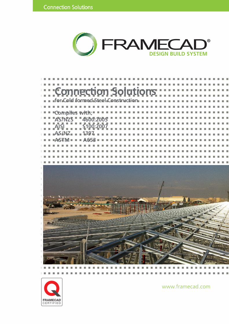
FRAMECAD® Construction Connectors are designed for speed, suitability and performance and are designed to deliver the most advanced end-to-end steel frame building solution.
The range includes connectors for steel truss, wall and joist assembly required for construction. FRAMECAD® connectors are designed with 4 main objectives - Design, Speed, Suitability and Performance.
DESIGN - Ease of design with correct information specified in FRAMECAD® Software to deliver robust and reliable structures.
SPEED - All our connectors have been selected to optimise the speed and efficiency of the FRAMECAD® building system. Using FRAMECAD® screws reduces labour costs by making it quicker and easier to fix screws consistently, helping business reach optimum production rates, both in the factory and on-site.
SUITABILITY - With over Twenty Five years’ experience in CFS (Cold Formed Steel Construction) FRAMECAD® has identified and developed a range of FRAMECAD® Certified Connectors that work specifically alongside our FRAMECAD® cold formed steel construction.
It is essential to use the specified FRAMECAD® Fasteners as they form a critical part of the connector’s tested performance.
PERFORMANCE - The design capacity of our connector range has been calculated in accordance with AS/NZ 4600:2005 and AISI S100:2007.FRAMECAD® Fasteners have been tested according to the AS/NZS 4600:2005 and AISI S100:2007 in our laboratories to ensure they are compatible with our FRAMECAD® Building Systems and meet relevant international recognised manufacturing standards.
All our Connectors are manufactured to steel grade AS/NZS 1397 G350 and are produced by ISO 9001 certified manufacturing facilities and have been tested for shear and tensile strength. Additionally, FRAMECAD®
Connectors are coated in corrosion retardant that give high visibility for your quality assurance process, during manufacturing and on-site.
FRAMECAD® Connectors are made from top quality Z275 galvanised material then further protected with FRAMECAD® Long Life Green protection coating for further corrosion protection.
DESIGN & BUILD SYSTEM
Beware of non-compliant Connectors. Brackets and connectors made from cheap or scrap metal often will not comply.
The FRAMECAD® Connector range are fully designed and manufactured to have both the correct strength and ductility to; 1. provide high strength connection of members2. provide the appropriate flexibility for dynamic loads e.g. wind or earthquake.FRAMECAD® materials are used to meet both these requirements and comply with the building code.
www.framecad.com © FRAMECAD Ltd. 2013 - All rights reserved
Pg. 10
Pg. 12
Pg. 6Pg. 16Pg. 8
Pg. 14
Pg. 4
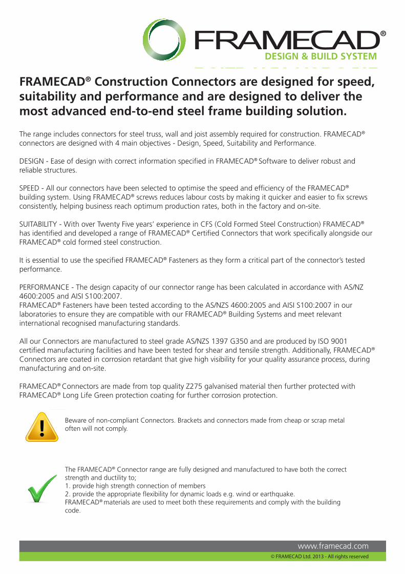
Connector CategoryBracket - Frame to Frame Connection -Tri Fix ( Left and Right) Page 4Multi Fix Connector Page 6Twist Fix Strap Page 8
Anchor - Frame to Floor Connection -Hold Down Fix & Washer Page 10
Bracing - Frame System Restraint -Strap Fix Page 12Strap Fix Tensioner Page 13
Plate - Frame and Connection StrengtheningFix Plate Connector Page 14Apex Heel Plate Page 16
FRAMECAD Connectors and Fasteners are:• Designed into FRAMECAD® Software• Compliant with AS/NZS 4600:2005, and AISI S100:2007.• Manufactured to Steel Grade AS/NZ 1397 G350 - 0.95 - 1.15 BMT, otherwise specified.• Site Friendly - easy and flexible to install on site.• Versatile - as connectors can be used for several construction applications.• FRAMECAD® Certified and compliant with many building standards
FRAMECAD® Connector Solutions
Page1
www.framecad.com © FRAMECAD Ltd. 2013 - All rights reserved

FRAMECAD® Specified Screw Fasteners
Code Description
307387 10g - 16 x 19mm, HWH, Hex, DP, 1000hrs
002047 10g - 16 x 16mm, HWH, Hex, DP, 1000hrs
001869 10g - 16 x 16mm, Flat, Ph#2, DP, 48hrs
001539 10g - 16 x 16mm, Flat, Ph#2, DP, 1000hrs
FRAMECAD® Certified Connectors are based upon physical testing using FRAMECAD® Fasteners and the following criteria:
1. No Substitution: The products specified in this guide must not be substituted with other products.2. Design Capacity Code and Standard AS/NZS 4600:2005 and AISI S100:2007.3. Constructions using FRAMECAD® products must be used in accordance with the regulations of the Local or International Building Code Authorities.4. Correct Installation: Installation of FRAMECAD® products must be strictly in accordance with the instructions in this guide.5. Current Guide Version Used: The current version of this guide, including any amendments or additions, must be used.
We advised to check with FRAMECAD® for updates at least every three months via the web site: www.framecad.com
FRAMECAD® Product Certification
FRAMECAD® products are structurally adequate provided they are designed, installed and used completely in accordance with this guide and signed off by the locally registered engineer.
This Certification applies only to:
1. Only Products in this guide.2. Products used in the specified applications and not damaged after manufacture and supply.
FRAMECAD® Connector Installation:
These notes are provided to ensure proper installation of FRAMECAD® Certified Connectors.
1. FRAMECAD® Certified Connectors are used in conjunction with FRAMECAD® Certified Fasteners.2. Do not drill additional fastener holes or modify FRAMECAD® Certified connectors, otherwise specified.3. Do not overload the joints or connectors - during construction or in service.4. Use proper safety equipment and due care in installing connectors.5. Any gaps in joints between the steel members must not exceed 1.5mm.6. Do not over-tighten screws.7. Use proper Fastener quantity as specified in this catalogue.8. Do not weld connectors.
Fastensings Manufactured in ISO 9001 and ISO certified facilities.
FRAMECAD® Connector Solutions
Page 2
www.framecad.com © FRAMECAD Ltd. 2013 - All rights reserved
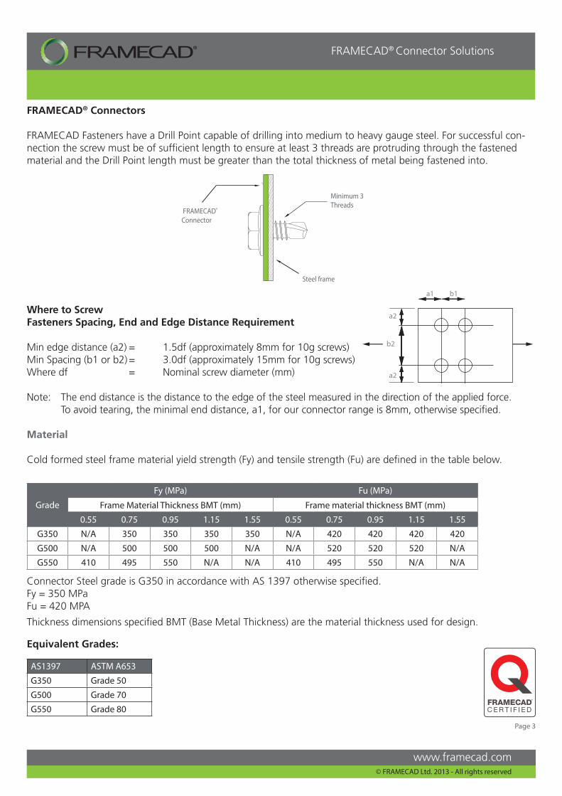
FRAMECAD® Connectors
FRAMECAD Fasteners have a Drill Point capable of drilling into medium to heavy gauge steel. For successful con-nection the screw must be of sufficient length to ensure at least 3 threads are protruding through the fastened material and the Drill Point length must be greater than the total thickness of metal being fastened into.
Where to ScrewFasteners Spacing, End and Edge Distance Requirement
Min edge distance (a2) = 1.5df (approximately 8mm for 10g screws) Min Spacing (b1 or b2) = 3.0df (approximately 15mm for 10g screws)Where df = Nominal screw diameter (mm)
Note: The end distance is the distance to the edge of the steel measured in the direction of the applied force. To avoid tearing, the minimal end distance, a1, for our connector range is 8mm, otherwise specified.
Material
Cold formed steel frame material yield strength (Fy) and tensile strength (Fu) are defined in the table below.
Grade
Fy (MPa) Fu (MPa)
Frame Material Thickness BMT (mm) Frame material thickness BMT (mm)
0.55 0.75 0.95 1.15 1.55 0.55 0.75 0.95 1.15 1.55
G350 N/A 350 350 350 350 N/A 420 420 420 420
G500 N/A 500 500 500 N/A N/A 520 520 520 N/A
G550 410 495 550 N/A N/A 410 495 550 N/A N/A
a1
b2
a2
b1
a2
AS1397 ASTM A653
G350 Grade 50
G500 Grade 70
G550 Grade 80
Equivalent Grades:
FRAMECAD®
Connector
Minimum 3 Threads
Steel frame
Connector Steel grade is G350 in accordance with AS 1397 otherwise specified. Fy = 350 MPaFu = 420 MPA
Thickness dimensions specified BMT (Base Metal Thickness) are the material thickness used for design.
Page 3
www.framecad.com
FRAMECAD® Connector Solutions
© FRAMECAD Ltd. 2013 - All rights reserved
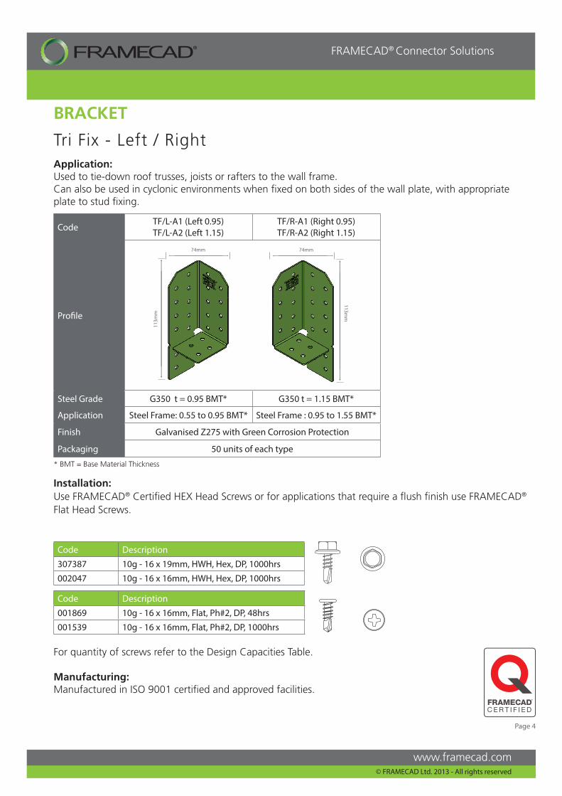
Tri Fix - Left / Right Application:Used to tie-down roof trusses, joists or rafters to the wall frame.Can also be used in cyclonic environments when fixed on both sides of the wall plate, with appropriate plate to stud fixing.
Installation:Use FRAMECAD® Certified HEX Head Screws or for applications that require a flush finish use FRAMECAD® Flat Head Screws.
Code Description
307387 10g - 16 x 19mm, HWH, Hex, DP, 1000hrs
002047 10g - 16 x 16mm, HWH, Hex, DP, 1000hrs
Code Description
001869 10g - 16 x 16mm, Flat, Ph#2, DP, 48hrs
001539 10g - 16 x 16mm, Flat, Ph#2, DP, 1000hrs
CodeTF/L-A1 (Left 0.95)TF/L-A2 (Left 1.15)
TF/R-A1 (Right 0.95)TF/R-A2 (Right 1.15)
Profile
Steel Grade G350 t = 0.95 BMT* G350 t = 1.15 BMT*
Application Steel Frame: 0.55 to 0.95 BMT* Steel Frame : 0.95 to 1.55 BMT*
Finish Galvanised Z275 with Green Corrosion Protection
Packaging 50 units of each type
74mm
113m
m
74mm
113mm
BRACKET
For quantity of screws refer to the Design Capacities Table.
Manufacturing:Manufactured in ISO 9001 certified and approved facilities.
* BMT = Base Material Thickness
Page 4
www.framecad.com
FRAMECAD® Connector Solutions
© FRAMECAD Ltd. 2013 - All rights reserved
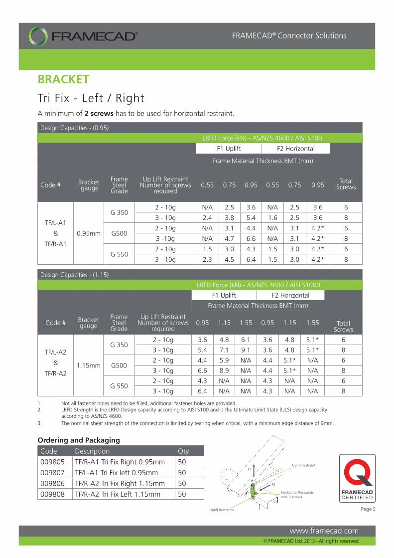
A minimum of 2 screws has to be used for horizontal restraint.
Tri Fix - Left / Right
Design Capacities - (1.15)
LRFD Force (kN) - AS/NZS 4600 / AISI S1000
F1 Uplift F2 Horizontal
Frame Material Thickness BMT (mm)
Total Screws
Code # Bracket gauge
Frame Steel Grade
Up Lift Restraint Number of screws
required 0.95 1.15 1.55 0.95 1.15 1.55
TF/L-A2
&
TF/R-A21.15mm
G 3502 - 10g 3.6 4.8 6.1 3.6 4.8 5.1* 6
3 - 10g 5.4 7.1 9.1 3.6 4.8 5.1* 8
G5002 - 10g 4.4 5.9 N/A 4.4 5.1* N/A 6
3 - 10g 6.6 8.9 N/A 4.4 5.1* N/A 8
G 5502 - 10g 4.3 N/A N/A 4.3 N/A N/A 6
3 - 10g 6.4 N/A N/A 4.3 N/A N/A 8
BRACKET
Design Capacities - (0.95)
LRFD Force (kN) - AS/NZS 4600 / AISI S100
F1 Uplift F2 Horizontal
Frame Material Thickness BMT (mm)
Total ScrewsCode # Bracket
gaugeFrame Steel Grade
Up Lift Restraint Number of screws
required0.55 0.75 0.95 0.55 0.75 0.95
TF/L-A1
&
TF/R-A1
0.95mm
G 3502 - 10g N/A 2.5 3.6 N/A 2.5 3.6 6
3 - 10g 2.4 3.8 5.4 1.6 2.5 3.6 8
G5002 - 10g N/A 3.1 4.4 N/A 3.1 4.2* 6
3 -10g N/A 4.7 6.6 N/A 3.1 4.2* 8
G 5502 - 10g 1.5 3.0 4.3 1.5 3.0 4.2* 6
3 - 10g 2.3 4.5 6.4 1.5 3.0 4.2* 8
F1
F2
Horizontal Restraints min. 2 screws
Uplift Restraint
Uplift Restraints
1. Not all fastener holes need to be filled, additional fastener holes are provided.2. LRFD Strength is the LRFD Design capacity according to AISI S100 and is the Ultimate Limit State (ULS) design capacity according to AS/NZS 4600.3. The nominal shear strength of the connection is limited by tearing when critical, with a minimum edge distance of 9mm.
Ordering and Packaging
Code Description Qty
009805 TF/R-A1 Tri Fix Right 0.95mm 50
009807 TF/L-A1 Tri Fix left 0.95mm 50
009806 TF/R-A2 Tri Fix Right 1.15mm 50
009808 TF/R-A2 Tri Fix Left 1.15mm 50
Page 5
www.framecad.com
FRAMECAD® Connector Solutions
© FRAMECAD Ltd. 2013 - All rights reserved
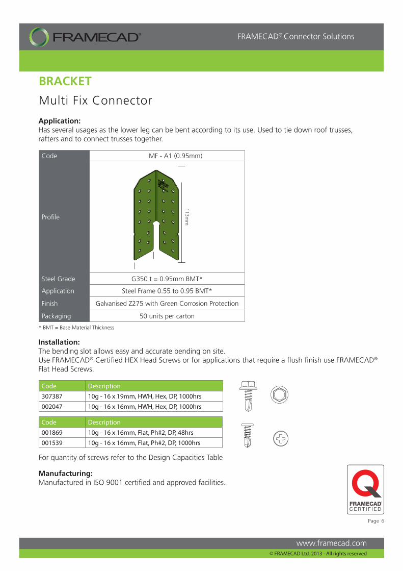
Multi Fix Connector
Application:Has several usages as the lower leg can be bent according to its use. Used to tie down roof trusses, rafters and to connect trusses together.
Code Description
307387 10g - 16 x 19mm, HWH, Hex, DP, 1000hrs
002047 10g - 16 x 16mm, HWH, Hex, DP, 1000hrs
Code Description
001869 10g - 16 x 16mm, Flat, Ph#2, DP, 48hrs
001539 10g - 16 x 16mm, Flat, Ph#2, DP, 1000hrs
Code MF - A1 (0.95mm)
Profile
Steel Grade G350 t = 0.95mm BMT*
Application Steel Frame 0.55 to 0.95 BMT*
Finish Galvanised Z275 with Green Corrosion Protection
Packaging 50 units per carton
113mm
For quantity of screws refer to the Design Capacities Table
Manufacturing:Manufactured in ISO 9001 certified and approved facilities.
BRACKET
Installation:The bending slot allows easy and accurate bending on site.Use FRAMECAD® Certified HEX Head Screws or for applications that require a flush finish use FRAMECAD® Flat Head Screws.
* BMT = Base Material Thickness
Page 6
www.framecad.com
FRAMECAD® Connector Solutions
© FRAMECAD Ltd. 2013 - All rights reserved
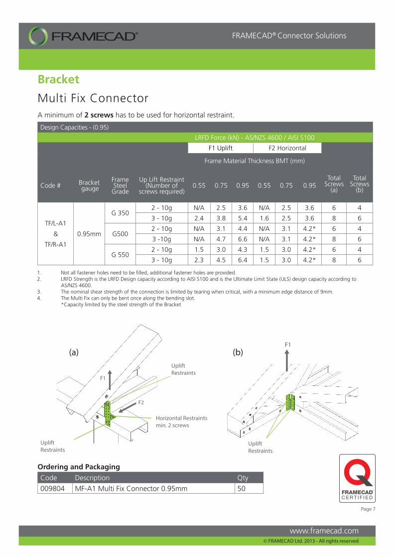
Multi Fix Connector
F1
Bracket
F1
F2
(a) (b)Uplift Restraints
Uplift Restraints
Uplift Restraints
Horizontal Restraintsmin. 2 screws
A minimum of 2 screws has to be used for horizontal restraint.
Design Capacities - (0.95)
LRFD Force (kN) - AS/NZS 4600 / AISI S100
F1 Uplift F2 Horizontal
Frame Material Thickness BMT (mm)
Total Screws
(a)
Total Screws
(b)Code # Bracket
gaugeFrame Steel Grade
Up Lift Restraint (Number of
screws required)0.55 0.75 0.95 0.55 0.75 0.95
TF/L-A1
&
TF/R-A1
0.95mm
G 3502 - 10g N/A 2.5 3.6 N/A 2.5 3.6 6 4
3 - 10g 2.4 3.8 5.4 1.6 2.5 3.6 8 6
G5002 - 10g N/A 3.1 4.4 N/A 3.1 4.2* 6 4
3 -10g N/A 4.7 6.6 N/A 3.1 4.2* 8 6
G 5502 - 10g 1.5 3.0 4.3 1.5 3.0 4.2* 6 4
3 - 10g 2.3 4.5 6.4 1.5 3.0 4.2* 8 6
1. Not all fastener holes need to be filled, additional fastener holes are provided.2. LRFD Strength is the LRFD Design capacity according to AISI S100 and is the Ultimate Limit State (ULS) design capacity according to AS/NZS 4600.3. The nominal shear strength of the connection is limited by tearing when critical, with a minimum edge distance of 9mm.4. The Multi Fix can only be bent once along the bending slot. *Capacity limited by the steel strength of the Bracket
Ordering and Packaging
Code Description Qty
009804 MF-A1 Multi Fix Connector 0.95mm 50
Page 7
www.framecad.com
FRAMECAD® Connector Solutions
© FRAMECAD Ltd. 2013 - All rights reserved
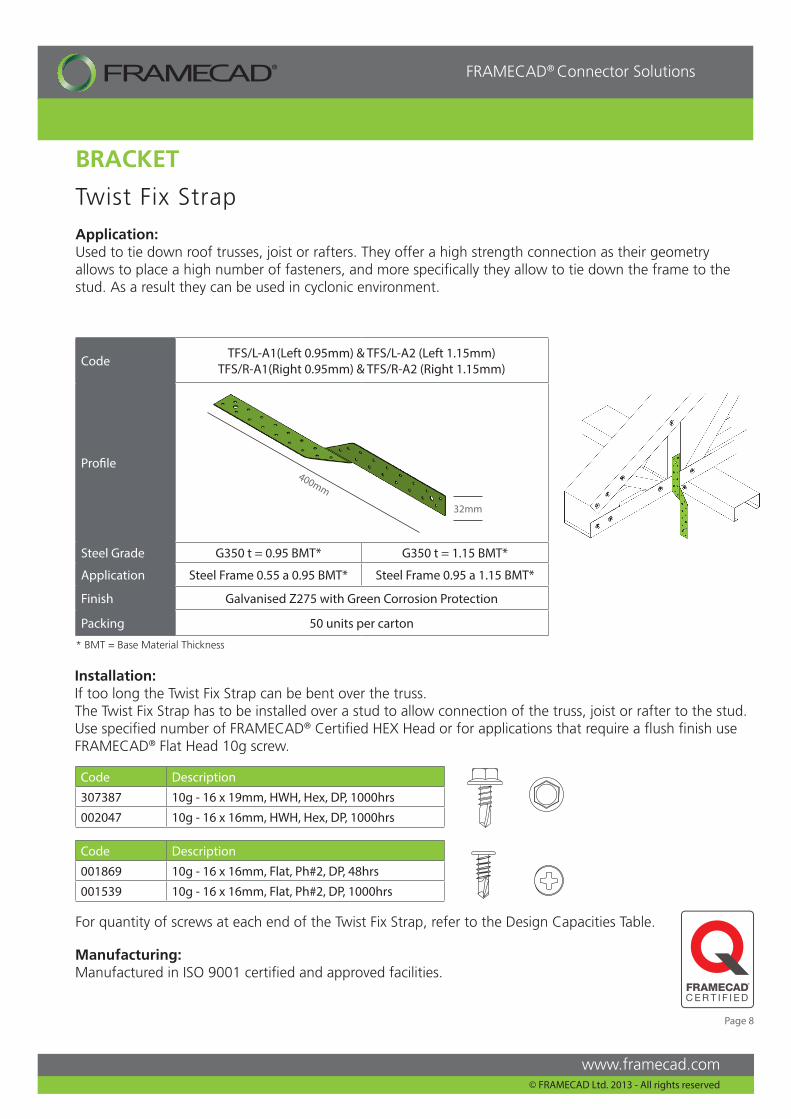
Twist Fix Strap
Installation:If too long the Twist Fix Strap can be bent over the truss.The Twist Fix Strap has to be installed over a stud to allow connection of the truss, joist or rafter to the stud.Use specified number of FRAMECAD® Certified HEX Head or for applications that require a flush finish use FRAMECAD® Flat Head 10g screw.
Application:Used to tie down roof trusses, joist or rafters. They offer a high strength connection as their geometry allows to place a high number of fasteners, and more specifically they allow to tie down the frame to the stud. As a result they can be used in cyclonic environment.
Code TFS/L-A1(Left 0.95mm) & TFS/L-A2 (Left 1.15mm)TFS/R-A1(Right 0.95mm) & TFS/R-A2 (Right 1.15mm)
Profile
Steel Grade G350 t = 0.95 BMT* G350 t = 1.15 BMT*
Application Steel Frame 0.55 a 0.95 BMT* Steel Frame 0.95 a 1.15 BMT*
Finish Galvanised Z275 with Green Corrosion Protection
Packing 50 units per carton
400mm
32mm
Code Description
307387 10g - 16 x 19mm, HWH, Hex, DP, 1000hrs
002047 10g - 16 x 16mm, HWH, Hex, DP, 1000hrs
Code Description
001869 10g - 16 x 16mm, Flat, Ph#2, DP, 48hrs
001539 10g - 16 x 16mm, Flat, Ph#2, DP, 1000hrs
Manufacturing:Manufactured in ISO 9001 certified and approved facilities.
BRACKET
For quantity of screws at each end of the Twist Fix Strap, refer to the Design Capacities Table.
* BMT = Base Material Thickness
Page 8
www.framecad.com
FRAMECAD® Connector Solutions
© FRAMECAD Ltd. 2013 - All rights reserved
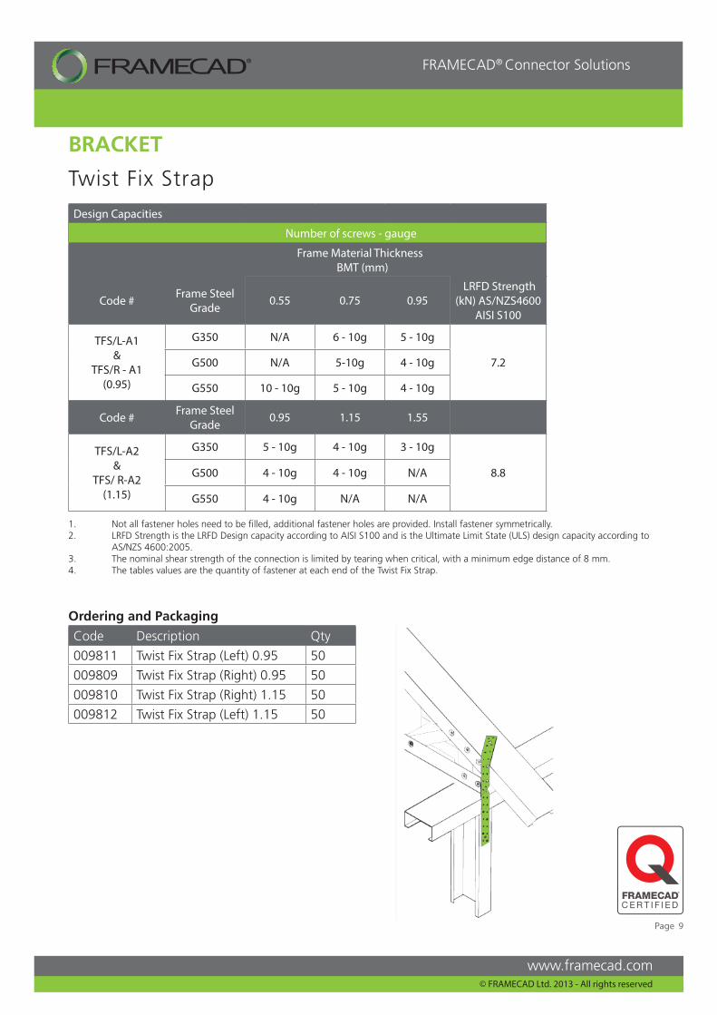
Design Capacities
Number of screws - gauge
Frame Material Thickness BMT (mm)
Code # Frame Steel Grade
0.55 0.75 0.95 LRFD Strength
(kN) AS/NZS4600 AISI S100
TFS/L-A1 &
TFS/R - A1(0.95)
G350 N/A 6 - 10g 5 - 10g
7.2G500 N/A 5-10g 4 - 10g
G550 10 - 10g 5 - 10g 4 - 10g
Code # Frame Steel Grade
0.95 1.15 1.55
TFS/L-A2 &
TFS/ R-A2(1.15)
G350 5 - 10g 4 - 10g 3 - 10g
8.8G500 4 - 10g 4 - 10g N/A
G550 4 - 10g N/A N/A
Twist Fix Strap
BRACKET
1. Not all fastener holes need to be filled, additional fastener holes are provided. Install fastener symmetrically.2. LRFD Strength is the LRFD Design capacity according to AISI S100 and is the Ultimate Limit State (ULS) design capacity according to AS/NZS 4600:2005.3. The nominal shear strength of the connection is limited by tearing when critical, with a minimum edge distance of 8 mm.4. The tables values are the quantity of fastener at each end of the Twist Fix Strap.
Ordering and Packaging
Code Description Qty
009811 Twist Fix Strap (Left) 0.95 50
009809 Twist Fix Strap (Right) 0.95 50
009810 Twist Fix Strap (Right) 1.15 50
009812 Twist Fix Strap (Left) 1.15 50
Page 9
www.framecad.com
FRAMECAD® Connector Solutions
© FRAMECAD Ltd. 2013 - All rights reserved
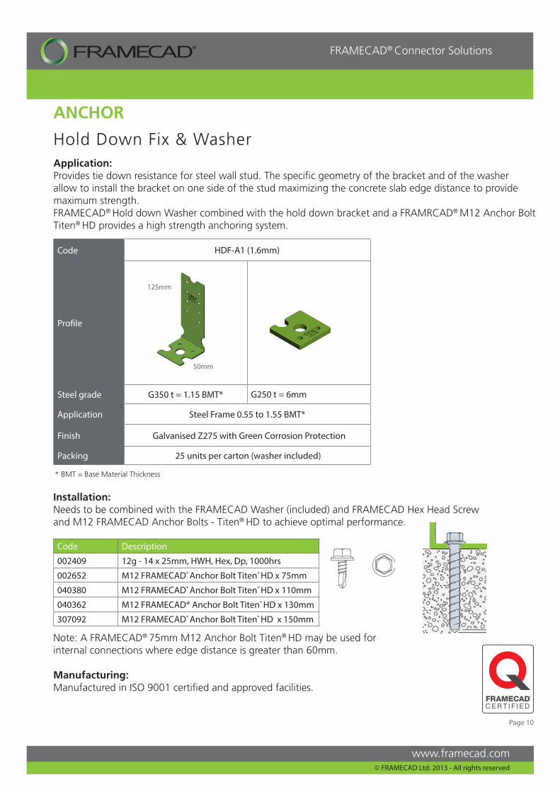
Code HDF-A1 (1.6mm)
Profile
Steel grade G350 t = 1.15 BMT* G250 t = 6mm
Application Steel Frame 0.55 to 1.55 BMT*
Finish Galvanised Z275 with Green Corrosion Protection
Packing 25 units per carton (washer included)
Hold Down Fix & Washer
ANCHOR
125mm
50mm
Application:Provides tie down resistance for steel wall stud. The specific geometry of the bracket and of the washer allow to install the bracket on one side of the stud maximizing the concrete slab edge distance to provide maximum strength.FRAMECAD® Hold down Washer combined with the hold down bracket and a FRAMRCAD® M12 Anchor Bolt Titen® HD provides a high strength anchoring system.
Installation:Needs to be combined with the FRAMECAD Washer (included) and FRAMECAD Hex Head Screw and M12 FRAMECAD Anchor Bolts - Titen® HD to achieve optimal performance.
Code Description
002409 12g - 14 x 25mm, HWH, Hex, Dp, 1000hrs
002652 M12 FRAMECAD® Anchor Bolt Titen® HD x 75mm
040380 M12 FRAMECAD® Anchor Bolt Titen® HD x 110mm
040362 M12 FRAMECAD® Anchor Bolt Titen® HD x 130mm
307092 M12 FRAMECAD® Anchor Bolt Titen® HD x 150mm
Note: A FRAMECAD® 75mm M12 Anchor Bolt Titen® HD may be used for internal connections where edge distance is greater than 60mm.
Manufacturing:Manufactured in ISO 9001 certified and approved facilities.
* BMT = Base Material Thickness
Page 10
www.framecad.com
FRAMECAD® Connector Solutions
© FRAMECAD Ltd. 2013 - All rights reserved
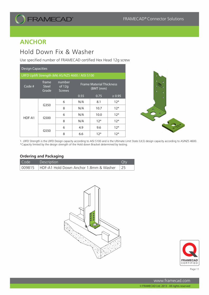
Design Capacities
LRFD Uplift Strength (kN) AS/NZS 4600 / AISI S100
Code #frame Steel
Grade
number of 12g Screws
Frame Material Thickness (BMT (mm)
0.55 0.75 ≥ 0.95
HDF-A1
G3506 N/A 8.1 12*
8 N/A 10.7 12*
G5006 N/A 10.0 12*
8 N/A 12* 12*
G5506 4.9 9.6 12*
8 6.6 12* 12*
Hold Down Fix & Washer
ANCHOR
Use specified number of FRAMECAD certified Hex Head 12g screw
1. LRFD Strength is the LRFD Design capacity according to AISI S100 and is the Ultimate Limit State (ULS) design capacity according to AS/NZS 4600.*Capacity limited by the design strength of the Hold down Bracket determined by testing.
Ordering and Packaging
Code Description Qty
009815 HDF-A1 Hold Down Anchor 1.8mm & Washer 25
Page 11
www.framecad.com
FRAMECAD® Connector Solutions
© FRAMECAD Ltd. 2013 - All rights reserved
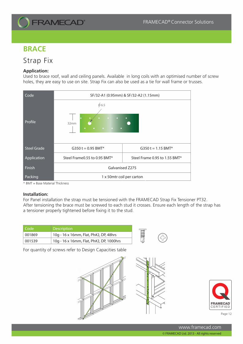
Code SF/32-A1 (0.95mm) & SF/32-A2 (1.15mm)
Profile
Steel Grade G350 t = 0.95 BMT* G350 t = 1.15 BMT*
Application Steel Frame0.55 to 0.95 BMT* Steel Frame 0.95 to 1.55 BMT*
Finish Galvanised Z275
Packing 1 x 50mtr coil per carton
Strap Fix
Installation:For Panel installation the strap must be tensioned with the FRAMECAD Strap Fix Tensioner PT32.After tensioning the brace must be screwed to each stud it crosses. Ensure each length of the strap has a tensioner properly tightened before fixing it to the stud.
Code Description
001869 10g - 16 x 16mm, Flat, Ph#2, DP, 48hrs
001539 10g - 16 x 16mm, Flat, Ph#2, DP, 1000hrs
32mm
O 6.5
BRACE
Application:Used to brace roof, wall and ceiling panels. Available in long coils with an optimised number of screw holes, they are easy to use on site. Strap Fix can also be used as a tie for wall frame or trusses.
For quantity of screws refer to Design Capacities table
* BMT = Base Material Thickness
Page 12
www.framecad.com
FRAMECAD® Connector Solutions
© FRAMECAD Ltd. 2013 - All rights reserved
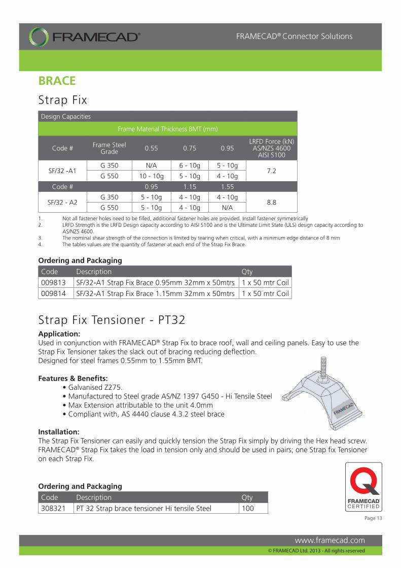
Strap Fix Tensioner - PT32
BRACE
Design Capacities
Frame Material Thickness BMT (mm)
Code # Frame Steel Grade 0.55 0.75 0.95
LRFD Force (kN) AS/NZS 4600
AISI S100
SF/32 -A1G 350 N/A 6 - 10g 5 - 10g
7.2G 550 10 - 10g 5 - 10g 4 - 10g
Code # 0.95 1.15 1.55
SF/32 - A2G 350 5 - 10g 4 - 10g 4 - 10g
8.8G 550 5 - 10g 4 - 10g N/A
Strap Fix
Application:Used in conjunction with FRAMECAD® Strap Fix to brace roof, wall and ceiling panels. Easy to use the Strap Fix Tensioner takes the slack out of bracing reducing deflection. Designed for steel frames 0.55mm to 1.55mm BMT.
Features & Benefits: • Galvanised Z275. • Manufactured to Steel grade AS/NZ 1397 G450 - Hi Tensile Steel • Max Extension attributable to the unit 4.0mm • Compliant with, AS 4440 clause 4.3.2 steel brace
Installation:The Strap Fix Tensioner can easily and quickly tension the Strap Fix simply by driving the Hex head screw. FRAMECAD® Strap Fix takes the load in tension only and should be used in pairs; one Strap fix Tensioner on each Strap Fix.
1. Not all fastener holes need to be filled, additional fastener holes are provided. Install fastener symmetrically2. LRFD Strength is the LRFD Design capacity according to AISI S100 and is the Ultimate Limit State (ULS) design capacity according to AS/NZS 4600.3. The nominal shear strength of the connection is limited by tearing when critical, with a minimum edge distance of 8 mm4. The tables values are the quantity of fastener at each end of the Strap Fix Brace.
Ordering and Packaging
Code Description Qty
009813 SF/32-A1 Strap Fix Brace 0.95mm 32mm x 50mtrs 1 x 50 mtr Coil
009814 SF/32-A1 Strap Fix Brace 1.15mm 32mm x 50mtrs 1 x 50 mtr Coil
Ordering and Packaging
Code Description Qty
308321 PT 32 Strap brace tensioner Hi tensile Steel 100 Page 13
www.framecad.com
FRAMECAD® Connector Solutions
© FRAMECAD Ltd. 2013 - All rights reserved
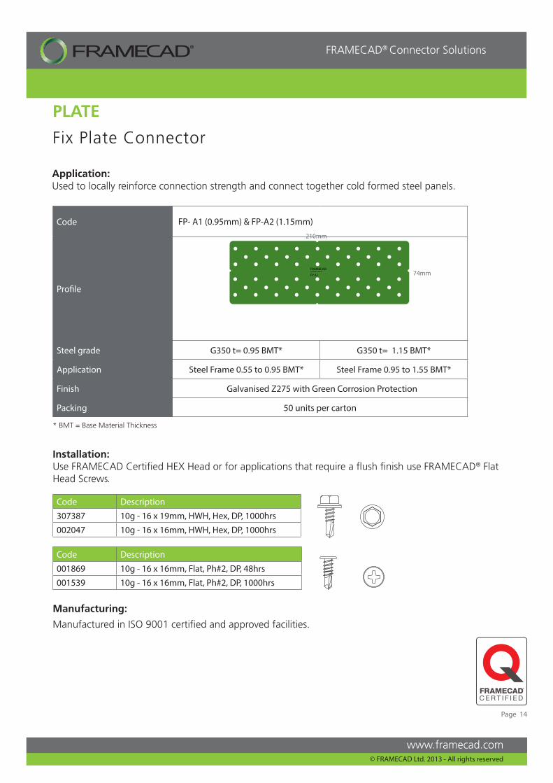
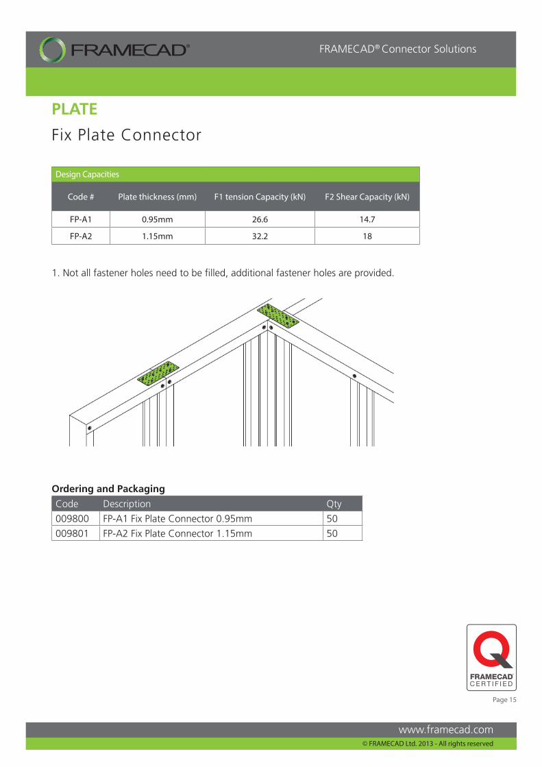
Fix Plate Connector
Application:Used to locally reinforce connection strength and connect together cold formed steel panels.
Code FP- A1 (0.95mm) & FP-A2 (1.15mm)
Profile
Steel grade G350 t= 0.95 BMT* G350 t= 1.15 BMT*
Application Steel Frame 0.55 to 0.95 BMT* Steel Frame 0.95 to 1.55 BMT*
Finish Galvanised Z275 with Green Corrosion Protection
Packing 50 units per carton
Code Description
307387 10g - 16 x 19mm, HWH, Hex, DP, 1000hrs
002047 10g - 16 x 16mm, HWH, Hex, DP, 1000hrs
Code Description
001869 10g - 16 x 16mm, Flat, Ph#2, DP, 48hrs
001539 10g - 16 x 16mm, Flat, Ph#2, DP, 1000hrs
Manufacturing:
Manufactured in ISO 9001 certified and approved facilities.
PLATE
74mm
Installation:Use FRAMECAD Certified HEX Head or for applications that require a flush finish use FRAMECAD® Flat Head Screws.
210mm
* BMT = Base Material Thickness
Page 14
www.framecad.com
FRAMECAD® Connector Solutions
© FRAMECAD Ltd. 2013 - All rights reserved
Design Capacities
Code # Plate thickness (mm) F1 tension Capacity (kN) F2 Shear Capacity (kN)
FP-A1 0.95mm 26.6 14.7
FP-A2 1.15mm 32.2 18
Fix Plate Connector
PLATE
1. Not all fastener holes need to be filled, additional fastener holes are provided.
Ordering and Packaging
Code Description Qty
009800 FP-A1 Fix Plate Connector 0.95mm 50
009801 FP-A2 Fix Plate Connector 1.15mm 50
Page 15
www.framecad.com
FRAMECAD® Connector Solutions
© FRAMECAD Ltd. 2013 - All rights reserved
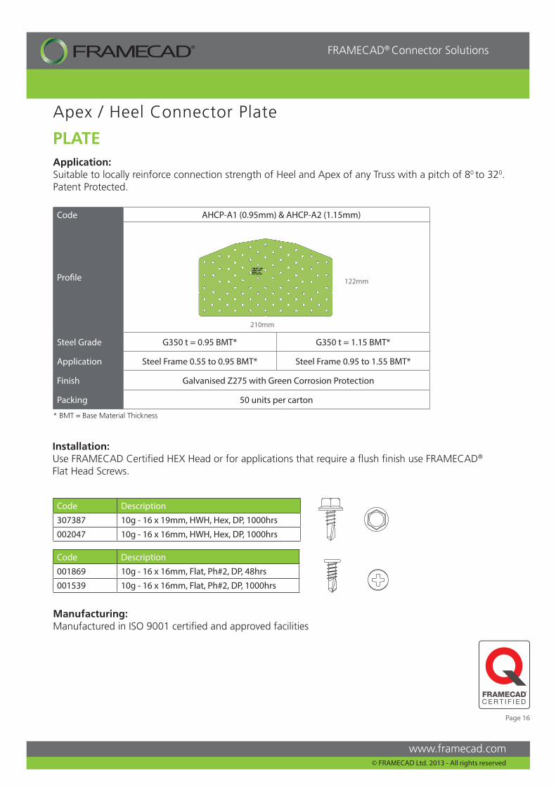
Code AHCP-A1 (0.95mm) & AHCP-A2 (1.15mm)
Profile
Steel Grade G350 t = 0.95 BMT* G350 t = 1.15 BMT*
Application Steel Frame 0.55 to 0.95 BMT* Steel Frame 0.95 to 1.55 BMT*
Finish Galvanised Z275 with Green Corrosion Protection
Packing 50 units per carton
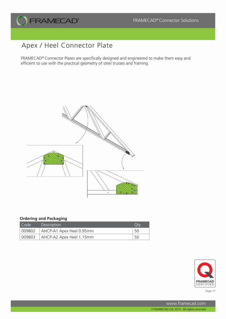
Apex / Heel Connector Plate
Code Description
307387 10g - 16 x 19mm, HWH, Hex, DP, 1000hrs
002047 10g - 16 x 16mm, HWH, Hex, DP, 1000hrs
Code Description
001869 10g - 16 x 16mm, Flat, Ph#2, DP, 48hrs
001539 10g - 16 x 16mm, Flat, Ph#2, DP, 1000hrs
122mm
210mm
PLATEApplication:Suitable to locally reinforce connection strength of Heel and Apex of any Truss with a pitch of 80 to 320. Patent Protected.
Installation:Use FRAMECAD Certified HEX Head or for applications that require a flush finish use FRAMECAD®
Flat Head Screws.
Manufacturing:Manufactured in ISO 9001 certified and approved facilities
* BMT = Base Material Thickness
Page 16
www.framecad.com
FRAMECAD® Connector Solutions
© FRAMECAD Ltd. 2013 - All rights reserved
PLATE
Apex / Heel Connector Plate
Ordering and Packaging
Code Description Qty
009802 AHCP-A1 Apex Heel 0.95mm 50
009803 AHCP-A2 Apex Heel 1.15mm 50
FRAMECAD® Connector Plates are specifically designed and engineered to make them easy and efficient to use with the practical geometry of steel trusses and framing.
Page 17
www.framecad.com
FRAMECAD® Connector Solutions
© FRAMECAD Ltd. 2013 - All rights reserved
English - Connectors 2013
This document has been published for the purpose of providing information of a general nature only. Further, no guarantee, warranty, or any other form of assurance is given as to the accuracy, currency or completeness of the information provided. Accordingly, any reliance on, or use, by you of any information contained within this document for any purpose whatsoever shall be entirely at your own risk, and any liability to you is expressly disclaimed to the maximum extent permitted by law.
FRAMECAD® logos and are trademarks and the property of FRAMECAD Ltd.
Copyright 2012 FRAMECAD Ltd. Reproduction of any part of this document is prohibited, except with the prior written consent of FRAMECAD Ltd.
We have offices here:
Auckland, New Zealand (Head Office) Dubai, UAEMelbourne, AustraliaJohannesburg, South AfricaDallas, USAHong Kong
For more information you can contact us atwww.framecad.com


![The antimicrobial case for the 9.7- inch iPad Pro, iPad ... · Dimensions 288(L) x 215(H) x 22(D) mm [including handle depth is 74mm]. Dimensions](https://img.pdfslide.us/doc/110x75/5e6cf6efb0859e0d9a1a720e/the-antimicrobial-case-for-the-97-inch-ipad-pro-ipad-dimensions-288l-x.jpg)