Embed Size (px)
Citation preview

Connection Design with the NDS and Technical Report 12Lori Koch, PEManager, Educational OutreachAmerican Wood Council 1
This webinar ispresented on behalf of
KM3

Slide 1
KM3 If you have time, I suggest increase the font sizes throughout the presentation. Maybe this is something that you can have Kim do. Also, check some of slides graphics as they may have the graphics cut off at the bottom of the slides.Kam-Biron, Michelle, 1/25/2017

This presentation is protected by US and International Copyright laws. Reproduction,
distribution, display and use of the presentation without written permission of the speaker is
prohibited.
© American Wood Council 2017
Copyright Materials
2
Course Description
This course will feature techniques for designing connections for wood members utilizing AWC's 2015 National Design Specification® (NDS®) for Wood Construction and Technical Report 12 - General Dowel Equations for Calculating Lateral Connection Values (TR12). Topics will include connection design philosophy and behavior, an overview of common fastener types, changes in the 2015 NDS related to cross-laminated timber, and design examples per TR12.
3

Learning Objectives
• On completion of this course, participants will:
1. Be familiar with current wood member connection solutions and applicable design requirements.
2. Be familiar with Technical Report 12 and provisions for connection design beyond NDS requirements.
3. Be able to recommend fastening guidelines for wood to steel, wood to concrete, and wood to wood connections.
4. Be able to describe effects of moisture on wood member connections and implement proper detailing to mitigate issues that may occur.
4

Outline
• Wood connection design philosophy
• Connection behavior• Serviceability challenges• Connection hardware and
fastening systems• Connection techniques • Design software• Where to get more
information
5

• Model wood cells as a bundle of straws• Bundle is very strong parallel to axis of the straws
Basic Concepts
Stronger Less strong
Parallel Perpendicular
6

Connecting Wood - Philosophy
• Wood likes compression parallel to grain• makes connecting wood very easy
7

• Wood likes compression parallel to grain• makes connecting wood very easy
Connecting Wood - Philosophy
8

Connecting Wood - Philosophy• Wood likes to take on load spread over its surface
9

Connecting Wood - Philosophy• Wood and tension perpendicular to grain
• Not recommended
Initiators:• notches• large diameter fasteners• hanging loads
10

Notching
Problem Solution
11

Split
Beam to Concrete
• Notched Beam Bearing• may cause splitting• not recommended
12

Beam to Concrete
• Notched Bearing Wall• alternate to beam notch
13
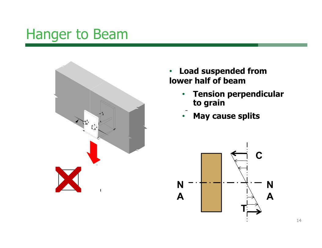
Hanger to Beam
• Load suspended from lower half of beam
• Tension perpendicular to grain
• May cause splits SplitSplit
C
T
NA
NA
14
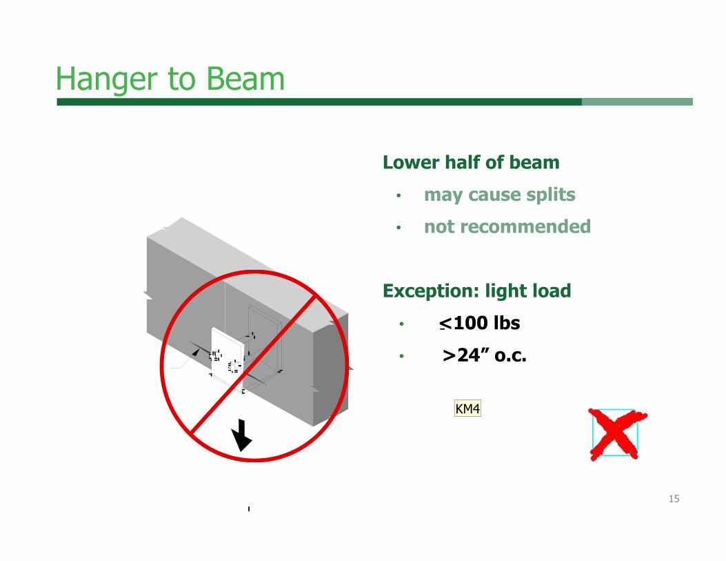
Hanger to Beam
Lower half of beam• may cause splits• not recommended
Exception: light load• <100 lbs• >24” o.c.Split
15
KM4

Slide 15
KM4 I believe this is per the exception is per the NDS, you might mention where it states this.Kam-Biron, Michelle, 1/25/2017

Hanger to Beam
• Load supported in upper half of beam
• Extended plates puts wood in compression when loaded
compression
Full wrap sling option
C
T
NA
NA
16
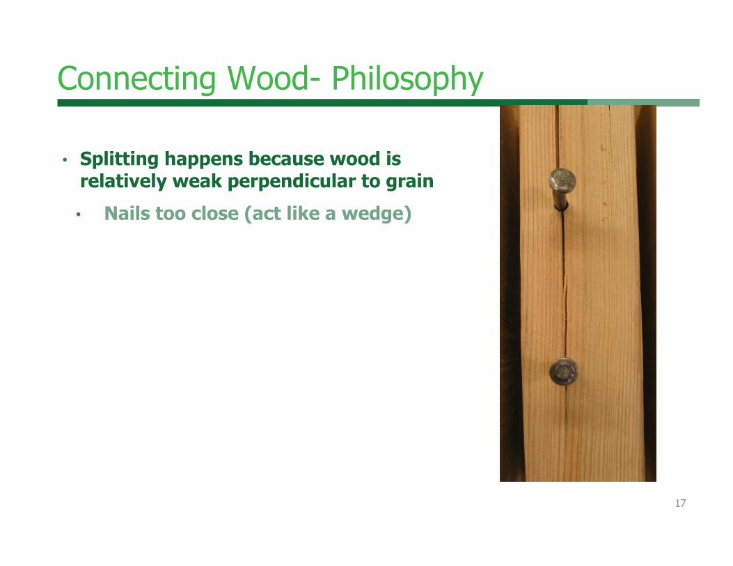
Connecting Wood- Philosophy
• Splitting happens because wood is relatively weak perpendicular to grain
• Nails too close (act like a wedge)
17

Nailing not staggered Nailing staggered
Framing
Wood StructuralPanel
Nail
1/8" GapBetween Panels
Nailing not staggered Nailing staggered
Staggered Nailing
Connecting Wood - Philosophy
18
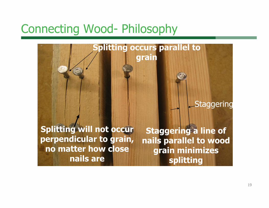
Splitting will not occur perpendicular to grain,
no matter how close nails are
Splitting occurs parallel to grain
Staggering
Staggering a line of nails parallel to wood
grain minimizes splitting
Connecting Wood- Philosophy
19

Connecting Wood - Philosophy• Wood, like other hygroscopic materials, moves in varying
environments
20

Connecting Wood - Philosophy• Fastener selection is key to connection ductility, strength,
performance
21

Outline
• Wood connection design philosophy
• Connection behavior• Serviceability challenges• Connection hardware and
fastening systems• Connection techniques • Design software• Where to get more
information
22

Connection Behavior
• Balance• Strength –• Ductility-
Load
Displacement
high strength, poor ductility
good strength, good ductility
low strength, good ductility
23

Connection Behavior
Load
Displacement
high strength, poor ductility
good strength, good ductility
low strength, good ductility
• Balance• Strength –
• Size and number of fasteners
• Ductility-• Fastener slenderness• Spacing• End distance
24

Outline
• Wood connection design philosophy
• Connection behavior• Serviceability challenges• Connection hardware and
fastening systems• Connection techniques • Design software• Where to get more
information
25

Connection Serviceability
• Issue: direct water ingress• Water is absorbed most quickly through wood end grain
No end caps or flashing
26
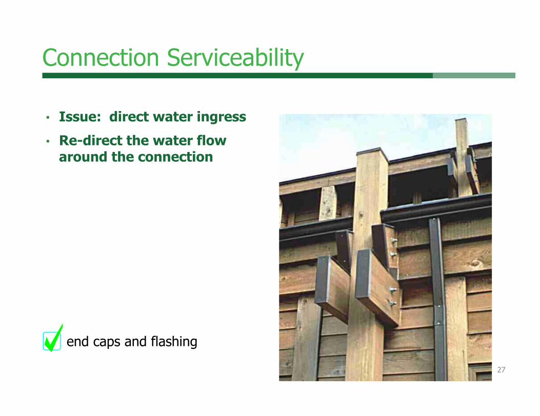
Connection Serviceability
• Issue: direct water ingress• Re-direct the water flow
around the connection
end caps and flashing
27

Connection Serviceability• Issue: direct water ingress• Or, let water out if it gets in...
Moisture trap -No weep holes
28

Moisture Changes In Wood
Causes dimensional changes perpendicular to grain
Growing tree is filled with water
As wood dries, it shrinksperp. to grain
Tang
entia
lly
Radially
29

Wood Shrinks
Woodmagazine.com30

Connection Serviceability• Moisture Effects
1% change in dimension for
every 4% change MC
31
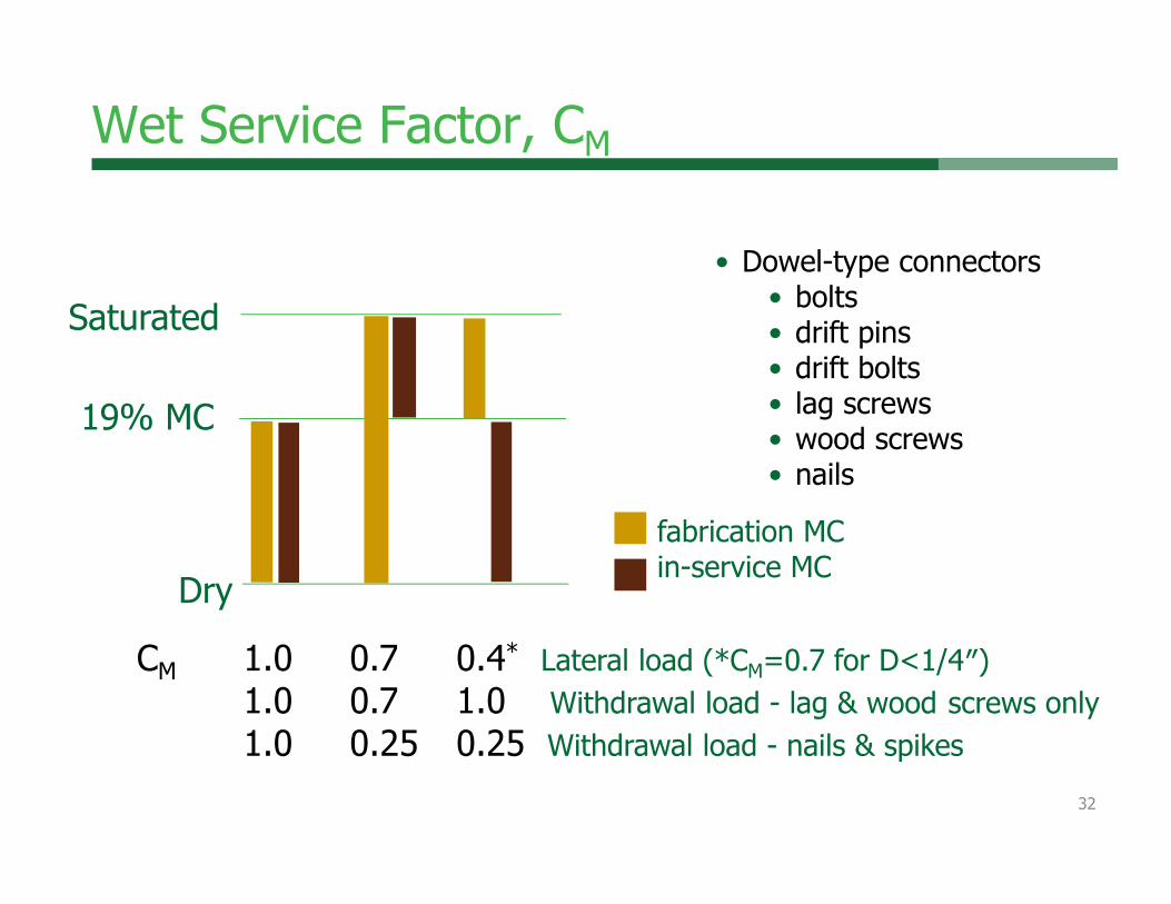
Wet Service Factor, CM
• Dowel-type connectors• bolts• drift pins• drift bolts• lag screws• wood screws• nails
CM 1.0 0.7 0.4* Lateral load (*CM=0.7 for D<1/4″)1.0 0.7 1.0 Withdrawal load - lag & wood screws only1.0 0.25 0.25 Withdrawal load - nails & spikes
Saturated
19% MC
Dryfabrication MCin-service MC
32

Wet Service Factor, CM
CM 0.4 Lateral load (D>1/4″)
CM = 1.0 if:1 fastener
2+ fasteners
split splice plates
Saturated
19% MC
Dry
fabrication MCin-service MC Table 11.3.3 footnote 2
33

Beam to Column
• Full-depth side plates• may cause splitting• wood shrinkage
34

Beam to Column
• Smaller side plates• transmit force• allow wood movement
35

Beam to Column
• Problem• shrinkage• tension perp
36

Beam to Wall
• Solution• bolts near bottom• minimizes effect of
shrinkage
Slotted hardware
37
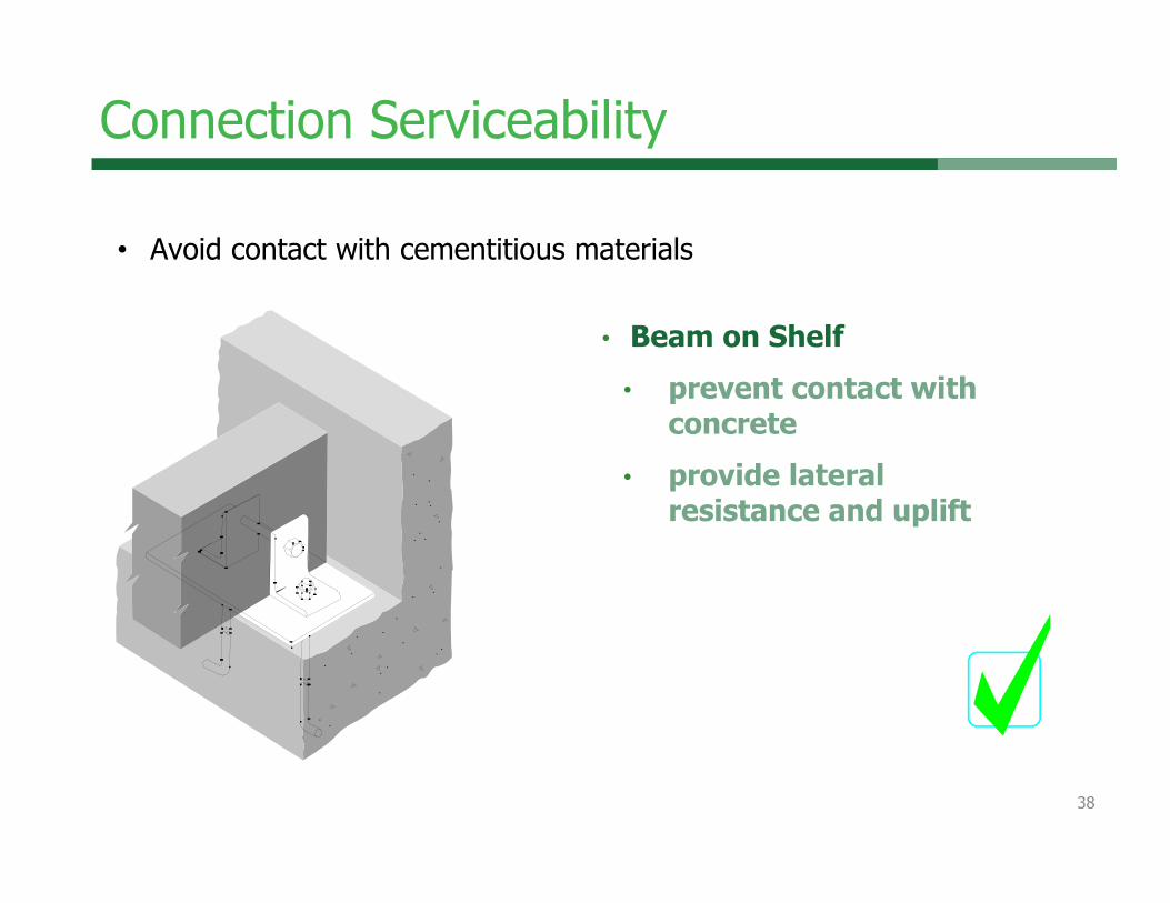
• Beam on Shelf• prevent contact with
concrete• provide lateral
resistance and uplift
• Avoid contact with cementitious materials
Connection Serviceability
38

Beam to Concrete
• Beam on Wall• prevent contact with
concrete• provide lateral
resistance and uplift• slotted to allow
longitudinal movement• typical for sloped beam
39

Beam to Masonry
• Application
Need 1/2” air gap between wood and masonry
• Application
40

Column to Base
• Problem• no weep holes in closed
shoe• moisture entrapped• decay can result
41

Column to Base
• Angle brackets• anchor bolts in brackets
42

Hidden Column Base
• Floor slab poured over connection
• will cause decay• not recommended
43

Column to Base
• Floor slab poured below connection
44

Outline
• Wood connection design philosophy
• Connection behavior• Serviceability challenges• Connection hardware and
fastening systems• Connection techniques • Design software• Where to get more
information
45

Mechanical Connectors
46

Traditional Connectors
• All-wood solution• time tested• practical• extreme efficiencies
available with computer numeric control (CNC) machining
www.tfguild.orgwww.timberframe.org
47

• Long History > 100 years
• Uses automated Computer numerical Control (CNC) milling technology • machine joints• pre-drill holes
• Timber Framer’s Guild -www.tfguild.org
Traditional Connectors
http://www.tfguild.org/downloads/TFEC-1-2010-with-Commentary.pdf
48

Traditional Connectors
• Wood dowel connection design technology now available
Schmidt, R.J. (2006): Timber Pegs – Considerations for Mortise and Tenon Joint Design, Structure Magazine, March 2006, NCSEA, 13(3):44-47. http://www.structuremag.org/wp-content/uploads/2014/09/SF-Timber-Pegs-March-061.pdf 49

•Common Fasteners• Nails • Staples • Wood Screws• Metal plate
connectors• Lag screws • Bolts
Mechanical Connectors
50

Typical Panel Connectors
51

Typical Panel Connectors
52Resource: Simpson Strong‐Tie

Typical Panel Connectors
53

• Included in U.S. design literature
Evaluation Reports (ER) are developed for proprietary products
Fastener Values
Fastener Type ReferenceBolts NDS or ERLag Screws NDS or ERWood Screws NDS or ERNails & Spikes NDS or ERSplit Ring Connectors NDSShear Plate Connectors NDSDrift Bolts & Drift Pins NDSMetal Plate Connectors ERHangers & Framing Anchors ER
Staples ER
54

Outline
• Wood connection design philosophy
• Connection behavior• Serviceability challenges• Connection hardware and
fastening systems• Connection techniques • Design software• Where to get more
information
55

Governing Codes for Wood Design
2015 NDS referenced in 2015 IBC
56
2015 NDS Chapter Reorganization
57
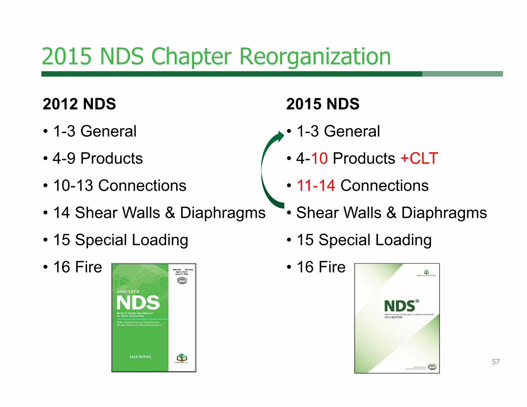
2012 NDS• 1-3 General• 4-9 Products• 10-13 Connections• 14 Shear Walls & Diaphragms• 15 Special Loading• 16 Fire
2015 NDS• 1-3 General• 4-10 Products +CLT• 11-14 Connections• Shear Walls & Diaphragms• 15 Special Loading• 16 Fire

NDS Chapter 11 – Mechanical Connections• ASD and LRFD accommodated through Table 11.3.1• Dowel fasteners• Split ring/shear plate• Timber rivets• Spike grids
New chapter numbering for 2015 NDS! 58

NDS Dowel-fastener Connections• 2015 NDS Chapter 12 (New location)• Can be used for any dowel-shaped fastener• Includes lateral and withdrawal provisions
• Bolts• Lag screws• Wood screws• Nails• Spikes• Drift bolts• Drift pins
59

Dowel-fastener withdrawal• Withdrawal calculated based on fastener penetration
• W value is per inch of fastener penetration• Threaded fasteners use thread penetration
• Lag screws• W = 1800 G3/2 D¾
• Wood screws• W = 2850 G2 D
• Nails (smooth shank)• W = 1380 G5/2 D No withdrawal in end grain allowed
for nails or wood screws!
60
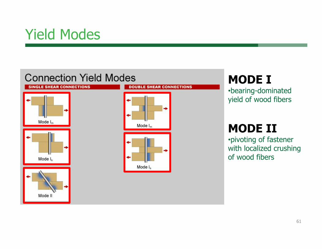
Yield Modes
MODE I•bearing-dominated yield of wood fibers
MODE II•pivoting of fastener with localized crushing of wood fibers
61

Yield Modes
MODE III•fastener yield in bending at one plastic hinge and bearing –dominated yield of wood fibersMODE IV•fastener yield in bending at two plastic hinges and bearing –dominated yield of wood fibers
62
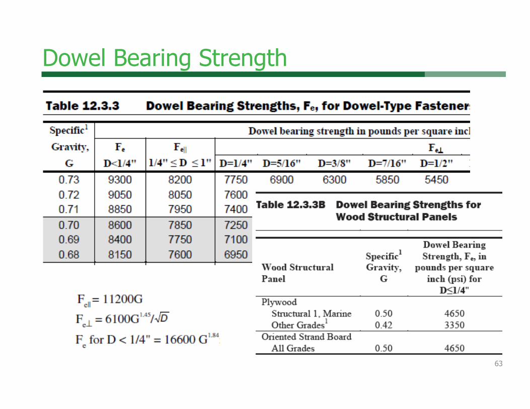
Dowel Bearing Strength
63
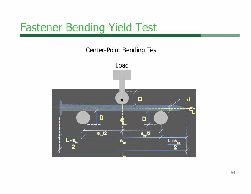
Fastener Bending Yield Test
Center-Point Bending Test
Load
64

Fastener Bending Yield Strength
65
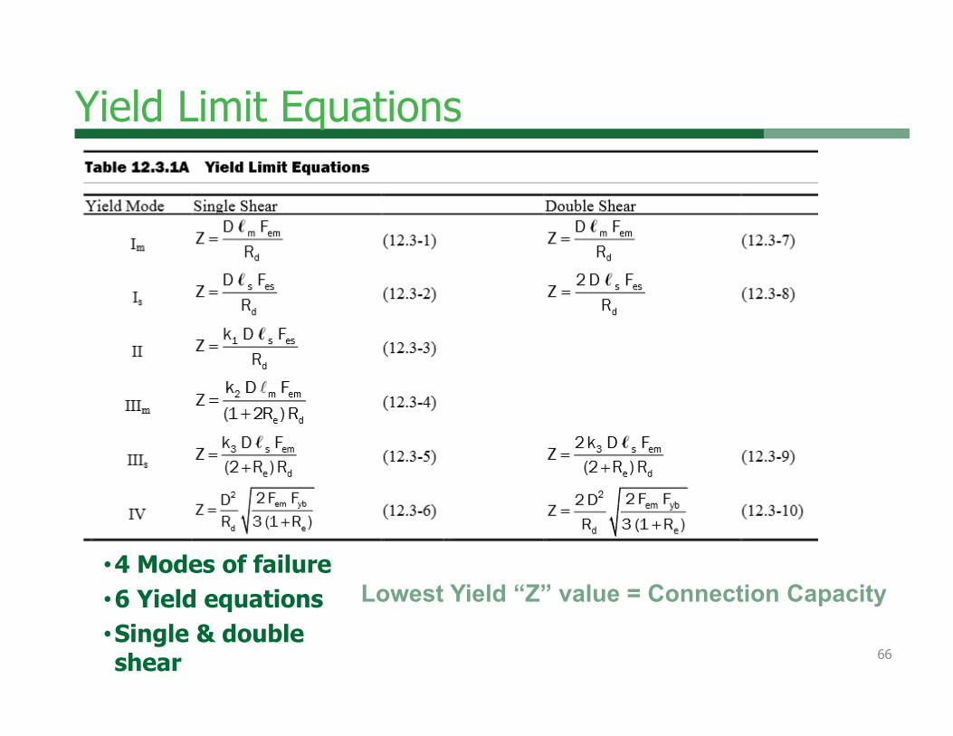
Yield Limit Equations
•4 Modes of failure•6 Yield equations•Single & double shear
Lowest Yield “Z” value = Connection Capacity
66
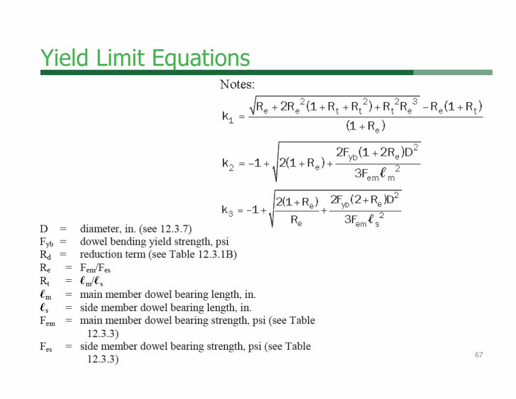
Yield Limit Equations
67

Yield Limit Equations
Also applied in TR12 equations!
68

Spacing, End, & Edge Distance
69

Spacing, End, & Edge Distance
70

Spacing, End, & Edge Distance
71
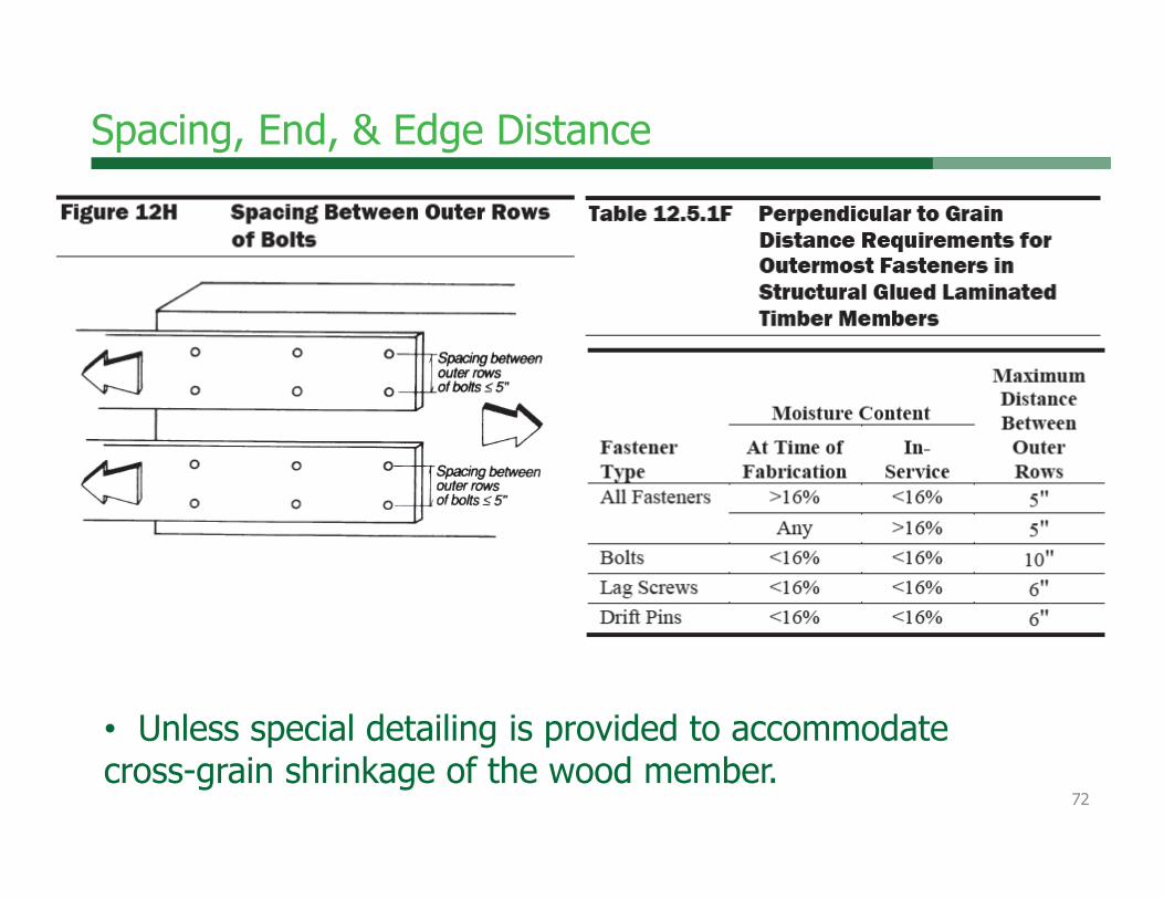
• Unless special detailing is provided to accommodate cross-grain shrinkage of the wood member.
Spacing, End, & Edge Distance
72
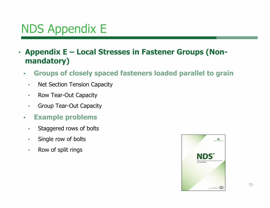
NDS Appendix E• Appendix E – Local Stresses in Fastener Groups (Non-
mandatory)• Groups of closely spaced fasteners loaded parallel to grain
• Net Section Tension Capacity
• Row Tear-Out Capacity
• Group Tear-Out Capacity
• Example problems• Staggered rows of bolts
• Single row of bolts
• Row of split rings
73

Chapter 12-Dowels
74

Chapter 12-Dowels
75

Dowel DiametersThreaded length < lm/4 lm
Dia. Fastener = D
Dia. Fastener = D
Threaded length < lm/4 lm
76

Dowel Diameters
Dia. Fastener = Dr
• NDS Chapter 12 Tables use Dr for lateral yield equations• Assumes shear plane passes through threads
lm
77

Chapter 12 – Dowel-type Fasteners
78
New

Chapter 12 – Dowel-type Fasteners
79
New

Chapter 12 – Dowel-type Fasteners
80
New

Chapter 12 – Dowel-type Fasteners
81
New
Non-uniform for CLT

• Adjust lm or ls to compensate for orthogonal grain orientations in adjacent layers
• Parallel to grain: Fe/Fe‖Example: ½” bolt in southern pine 3-ply CLT
with 1-½” laminationslm = t1‖ + t2 + t3‖ = 3(1.5) = 4.5”lm-adj = t1‖ + t2(Fe/Fe‖) + t3‖
=1.5 +1.5(3650/6150) +1.5 = 3.9”
82
Chapter 12 – Dowel-type Fasteners

83
Chapter 12 – Dowel-type Fasteners
New

Chapter 12 – Dowel-type Fasteners
• Lateral – any end grain• D<1/4” Ceg=0.67
• Lateral – any CLT edge• D>1/4” Ceg=0.67
84
New
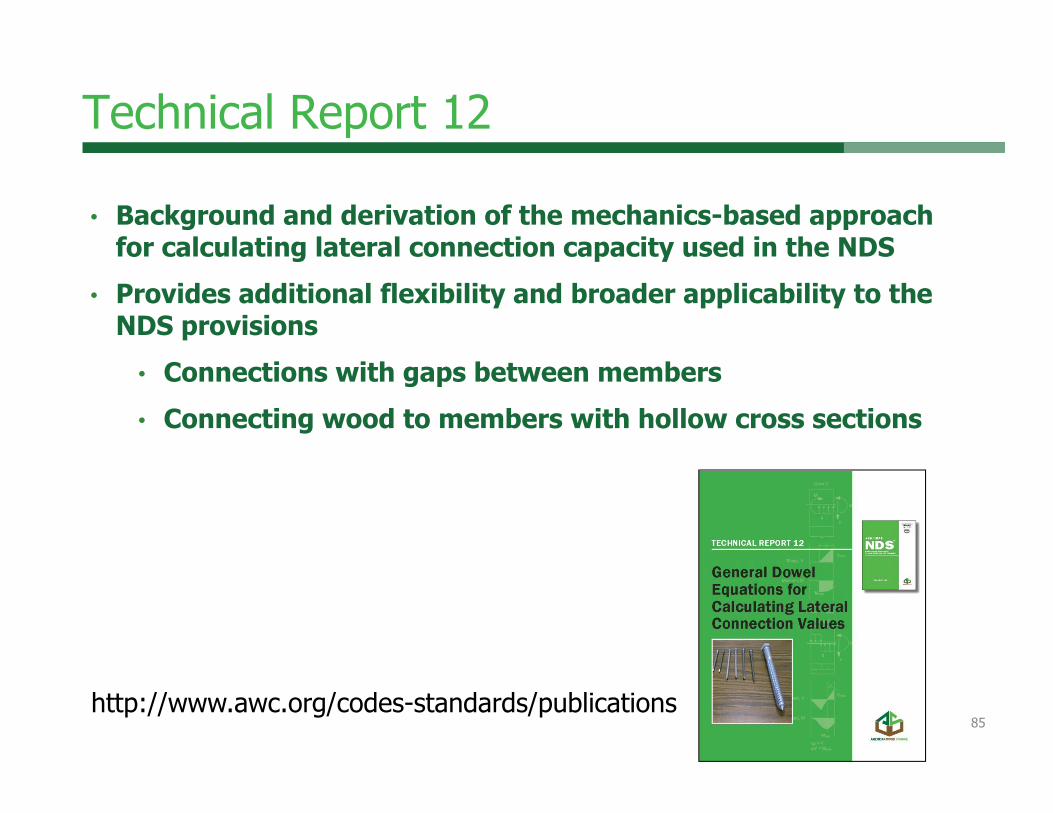
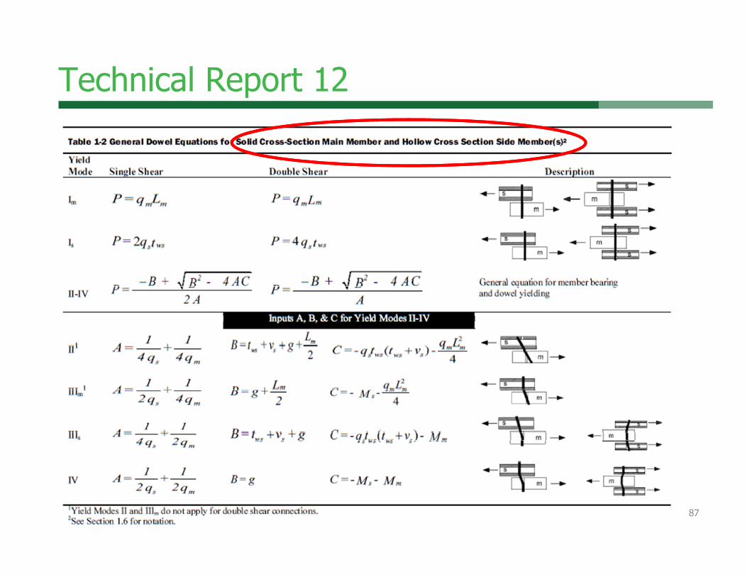
Technical Report 12
• Background and derivation of the mechanics-based approach for calculating lateral connection capacity used in the NDS
• Provides additional flexibility and broader applicability to the NDS provisions
• Connections with gaps between members• Connecting wood to members with hollow cross sections
http://www.awc.org/codes-standards/publications85

Technical Report 12
86
Technical Report 12
87

Technical Report 12
88

Technical Report 12•Allows for evaluation of connections with gaps between connected members
89

Technical Report 12• Tapered tip fasteners
• NDS 12.5.3 defines “E” as length of tapered tip• Lag screws – E defined in Appendix L
• Wood screws, nails – E assumed to be 2D
• Tapered tip does not count towards bearing length (Lm) in TR12 Tapered tip equations.
90

Technical Report 12• Tapered tip equations
• Mode Im
• Mode Is
• Mode II
• Mode IIIm
• Mode IIIs
• Mode IV
TR12 shows NDS approximations are <1% different from
using expanded equation!
91

Technical Report 12
• TR12 presents mechanics-based equations • Gives same results as NDS energy-based approach
• Equations in TR12 calculate P, must be divided by Rd (NDS Table 12.3.1B) to convert to NDS Z basis
• TR12 Appendix available with supplementary information
92

Technical Report 12 Appendix• Contains additional data for
TR12 equation inputs• Dowel bearing values for:
• Wood• Steel• Concrete• Stainless steel• Aluminum
• Dowel bending values for fastener materials: • Steel and stainless steel bolts
and lag screws• Low-to-medium carbon steel
nails• Hardened steel nails (including
post-frame ring-shank)
93

Example Problem #1
• Calculate W for ¼” diameter, 2.5” long lag screw connecting 2-2x SYP (G = 0.55) members
• W = 1800 G3/2 D¾ = 260 lbs/in (calculate or NDS Table 12.2A)• Calculate penetration into main member for withdrawal capacity
• NDS Appendix L gives lag screw dimensions• Length of unthreaded section = ¾”
• Length of threaded section (including tip) = 1¾”
• Length of threaded section (excluding tip) = 119/32”
• p = screw length – length of side member – length of tip
• p = 2.5” – 1.5” – (1¾” - 119/32”) = 0.84” of penetration
• Unadjusted capacity = W*p = (260 lbs/in * 0.84 in) = 219 lbs• Apply adjustment factors per Table 11.3.1 to get adjusted W’
94
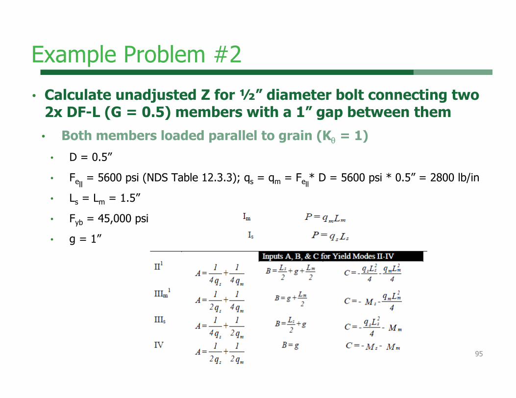
Example Problem #2 • Calculate unadjusted Z for ½” diameter bolt connecting two
2x DF-L (G = 0.5) members with a 1” gap between them• Both members loaded parallel to grain (K = 1)
• D = 0.5”
• Fell= 5600 psi (NDS Table 12.3.3); qs = qm = Fell
* D = 5600 psi * 0.5” = 2800 lb/in
• Ls = Lm = 1.5”
• Fyb = 45,000 psi
• g = 1”
95

Example Problem #2 • Calculate unadjusted Z for ½” diameter bolt connecting two
2x DF-L (G = 0.5) members with a 1” gap between them• Mm = Ms = (FbD3)/6 = (45,000 psi)*(0.5”^3)/6 = 937.5 lb-in
• Substituting values into TR12 equations yields P values• Divide P values by Rd to obtain Z
Mode P (lbs) Rd Z (lbs)
Im 4200 4K = 4 1050Is 4200 4K = 4 1050II 1163 3.6K= 3.6 323
IIIm 1211 3.2K = 3.2 378IIIs 1211 3.2K = 3.2 378IV 1285 3.2K = 3.2 402
Z = 323 lbs 96

Example Problem #3
• Compare lateral Z values for single shear nail connection at 6D, 8D, 10D, and 12D penetration using TR12 tapered tip equations
• 8d common nail D = 0.131”, tapered tip length, E = 2D = 0.262” • Main member Fem = 4,700 psi (loaded parallel to grain); ASTM
A653, Grade 33 steel side member, thickness = 0.06”, Fes = 61,850 psi
• Lm = p (penetration into main member); Ls = 0.06” (side member thickness)
Penetration Depth (p) Z (lbs) Controlling
mode12D (1.57") 97 IIIs10D (1.31") 97 IIIs8D (1.05") 97 IIIs6D (0.79") 79 II
97

Example Problem #3
• Compare Z values for single shear nail connection at 6D, 8D, 10D, and 12D penetration using NDS Lm assumption for tapered tip
• 8d common nail D = 0.131”, tapered tip length, E = 2D = 0.262” • Main member Fem = 4,700 psi (loaded parallel to grain); ASTM
A653, Grade 33 steel side member, thickness = 0.06”, Fes = 61,850 psi
• Lm = p – E/2 (NDS assumption) ; Ls = 0.06” (side member thickness)
Penetration Depth (p) Z (lbs) Controlling
mode12D (1.57") 97 IIIs10D (1.31") 97 IIIs8D (1.05") 97 IIIs6D (0.79") 78 II
98
Outline
• Wood connection design philosophy
• Connection behavior• Serviceability challenges• Connection hardware and
fastening systems• Connection techniques • Design software• Where to get more
information
99

http://www2.wwpa.org/TECHGUIDEPAGES/DesignSoftware/tabid/859/Default.aspx
•WWPA Lumber Design Suite
• Beams and Joists• Post and Studs• Wood to Wood
Shear Connections (nails, bolts, wood screws and lag screws)
Software Solutions Exist
100
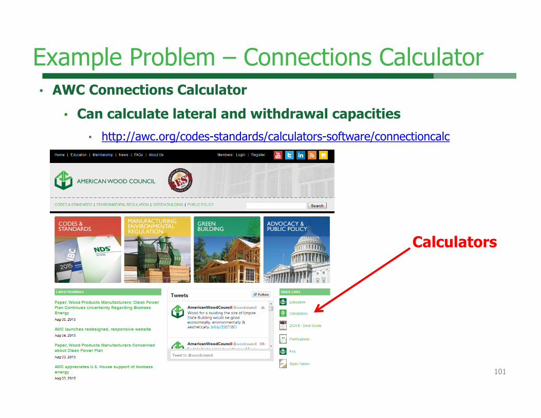
Example Problem – Connections Calculator • AWC Connections Calculator
• Can calculate lateral and withdrawal capacities• http://awc.org/codes-standards/calculators-software/connectioncalc
Calculators
101

Example Problem – Connections Calculator
Z’
102

Outline
• Wood connection design philosophy
• Connection behavior• Serviceability challenges• Connection hardware and
fastening systems• Connection techniques • Design software• Where to get more
information
103

• 2012 NDS
More info???
104
KM5

Slide 104
KM5 Update to 2015 mention the what's changed icon.Kam-Biron, Michelle, 1/25/2017

• Technical papers on Timber rivets: http://www.awc.org/helpoutreach/faq/faqFiles/Timber_rivets.html
• Timber rivets in structural composite lumber• Simplified analysis of timber rivet connections • Timber rivet connections in U.S. domestic species• Timber Rivets-Structure Magazine• Seismic Behavior of Timber Rivets in Wood Construction• Seismic Performance of Riveted Connections in Heavy
Timber Construction• Timber rivet suppliers
More info???
105

More info???• Load-carrying behavior of steel-to-timber dowel connections:
http://timber.ce.wsu.edu/Resources/papers/2-4-1.pdf• New Concealed Connectors Bring More Options for Timber
Structures http://www.structuremag.org/Archives/2007-1/p42-43D-Insights-ConcealedConnectorsJan07.pdf
106

Take Home Messages...• Transfer loads in compression / bearing whenever possible• Allow for dimensional changes in the wood due to potential in-
service moisture cycling• Avoid the use of details which induce tension perp stresses in
the wood• Avoid moisture entrapment in connections• Separate wood from direct contact with masonry or concrete• Avoid eccentricity in joint details• Minimize exposure of end grain
107
Connections
…and you thought connecting wood was complicated!
108

109

• This concludes The American Institute of Architects Continuing Education Systems Course
Questions?
110
American Wood [email protected]

![LISTADO DE JUEGOS - PinillaNumero Descripcion Foto 291 [NDS]Artic_Tale[EUR] 798 [NDS]Asphalt_Urban_GT_2[EUR] 306 [NDS]Assassins_Creed_Altairs_Chronicles[EUR] 285 [NDS]Assassins_Creed_Altairs_Chronicles[USA]](https://img.pdfslide.us/doc/110x75/5f07ebef7e708231d41f6db4/listado-de-juegos-numero-descripcion-foto-291-ndsartictaleeur-798-ndsasphalturbangt2eur.jpg)