Embed Size (px)
Citation preview
Reference Guide
17856.8.10 March 1996
Connecting SLC Systems asRemote I/O toPLC5 Processors
This document combines available PLC and SLC documentationto show you how you can communicate between these two types ofsystems over the remote I/O link.
remote I/O link
using a 1747DCMusing a 1747ASBusing a 1747SN
This information is in addition to the user documentation for theprocessors and communication modules discussed here. You shouldalready have a solid understanding of how to use these processors.Each section in this document lists additional documentation you canrefer to for detailed information.
This document is one of a larger set of reference materials to helpyou better use your PLC-5 processor. The 1785-6.8.x series ofdocuments provides individual documents for different applications.This reference set is continually expanding, so see yourAllen-Bradley sales representative or distributor for an up-to-date listof available reference documents.
For information about: See page:
Connecting remote I/OConnecting remote I/O
Using a 1747DCM Direct Communications module 2Using a 1747 DCM Direct Communications module
Application requirements
2
3Application requirements
Communicating over a remote I/O link 4
Connecting remote I/OConnecting remote I/O
Using a 1747ASB Remote I/O Adapter module 6Using a 1747 ASB Remote I/O Adapter module
Application requirements
6
8Application requirements
Communicating over a remote I/O link 9
Connecting remote I/O
Using a 1747SN Remote I/O Scanner module
Application requirements
Communicating over a remote I/O link
Sending blocktransfers
12
14
14
17
Introduction
Note: You can configure the
communication modules described in
this chapter to work with SLC 5/03 and
SLC 5/04 processors or with a
1747SN scanner.
Connecting SLC Systems as Remote I/O to PLC-5 Processors 2
17856.8.10 March 1996
DCM
COMM
CONFIGURATION
RACK SIZE1/4 1/2 3/4 1
RACK ADDR
FIRST I/O GROUP0 2 4 6
DATA RATE (K B/S)57.6 115.2 230.4
LINE 1 _______
SHIELD ______
LINE 2 _______
1747-DCM
SW
2S
W1
O N
12
34
56
78
O N
12
34
56
78
I/OGROUP
(LSB)
RACKADDRESS
(MSB)
RACKSIZE
DATARATE
XX
LAST RACK
CLR ON FLT
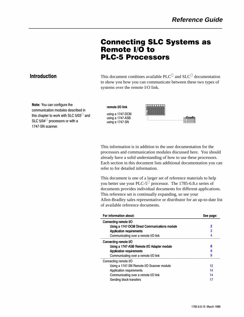
Using the 1747DCM Direct Communications Module
DCM modulePLC5 processor
To anotherremote I/O device
1770CD(Belden 9463)
Clear
ShieldBlue
82Ω or150Ωresistor
Clear
ShieldBlue
Terminate both ends of a remote I/O link
1770CD(Belden 9463)
PLC5 processorchannel 1 or 2
remote I/O link
SLC 500 processorwith 1747DCM module
FAULT
Connecting the remote I/O
Connecting SLC Systems as Remote I/O to PLC-5 Processors 3
17856.8.10 March 1996
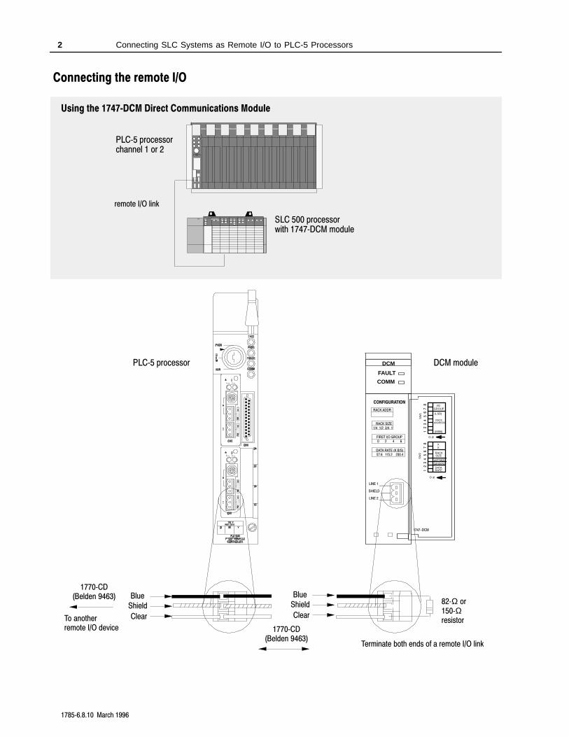
clear on faultlast rack
1747DCM module configurations
SW
1S
W2
8O N
12
34
56
7
SW1
O N
SW2 1
23
45
67
8
81
23
45
67
12
34
56
78
starting I/O group number
rack address
reserved
rack size
data rate
switch 1(SW1)
switch 2(SW2)
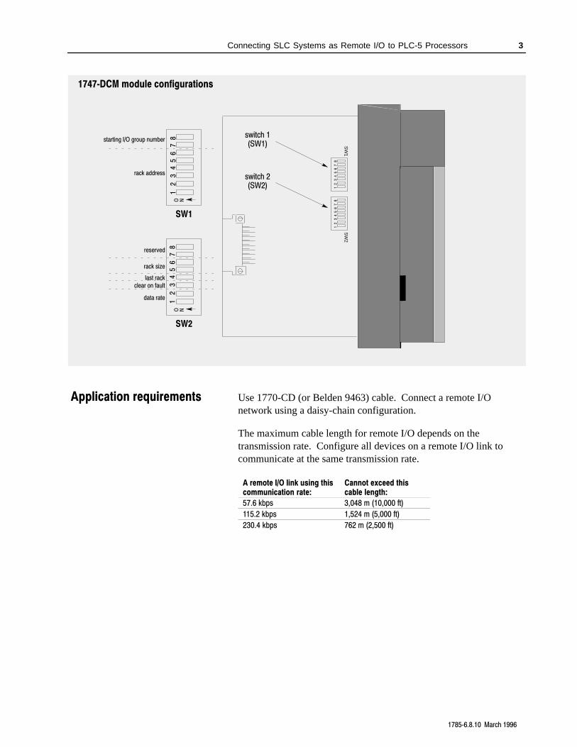
Use 1770-CD (or Belden 9463) cable. Connect a remote I/Onetwork using a daisy-chain configuration.
The maximum cable length for remote I/O depends on thetransmission rate. Configure all devices on a remote I/O link tocommunicate at the same transmission rate.
A remote I/O link using thiscommunication rate:
Cannot exceed thiscable length:
57.6 kbps 3,048 m (10,000 ft)
115.2 kbps 1,524 m (5,000 ft)
230.4 kbps 762 m (2,500 ft)
Application requirements
Connecting SLC Systems as Remote I/O to PLC-5 Processors 4
17856.8.10 March 1996
Installing a 1747DCM module
The installation procedures for the DCM module are the same as forany other discrete I/O or specialty module in a 1746 chassis.
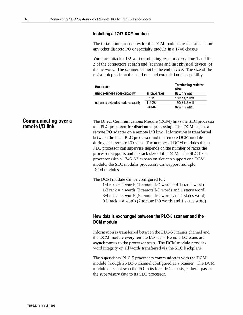
You must attach a 1/2-watt terminating resistor across line 1 and line2 of the connectors at each end (scanner and last physical device) ofthe network. The scanner cannot be the end device. The size of theresistor depends on the baud rate and extended node capability.
Baud rate:Terminating resistorsize:
sing e tended node capabilit all ba d rates 82 1/2 attusing extended node capability all baud rates 82 1/2 wattusing extended node capability all baud rates 82 1/2 watt
57.6K 150 1/2 watt
not using extended node capability 115.2K 150 1/2 wattnot using extended node capability
230.4K 82 1/2 watt
The Direct Communications Module (DCM) links the SLC processorto a PLC processor for distributed processing. The DCM acts as aremote I/O adapter on a remote I/O link. Information is transferredbetween the local PLC processor and the remote DCM moduleduring each remote I/O scan. The number of DCM modules that aPLC processor can supervise depends on the number of racks theprocessor supports and the rack size of the DCM. The SLC fixedprocessor with a 1746-A2 expansion slot can support one DCMmodule; the SLC modular processors can support multipleDCM modules.
The DCM module can be configured for:1/4 rack = 2 words (1 remote I/O word and 1 status word)1/2 rack = 4 words (3 remote I/O words and 1 status word)3/4 rack = 6 words (5 remote I/O words and 1 status word)full rack = 8 words (7 remote I/O words and 1 status word)
How data is exchanged between the PLC5 scanner and the
DCM module
Information is transferred between the PLC-5 scanner channel andthe DCM module every remote I/O scan. Remote I/O scans areasynchronous to the processor scan. The DCM module providesword integrity on all words transferred via the SLC backplane.
The supervisory PLC-5 processors communicates with the DCMmodule through a PLC-5 channel configured as a scanner. The DCMmodule does not scan the I/O in its local I/O chassis, rather it passesthe supervisory data to its SLC processor.
Communicating over aremote I/O link
Connecting SLC Systems as Remote I/O to PLC-5 Processors 5
17856.8.10 March 1996
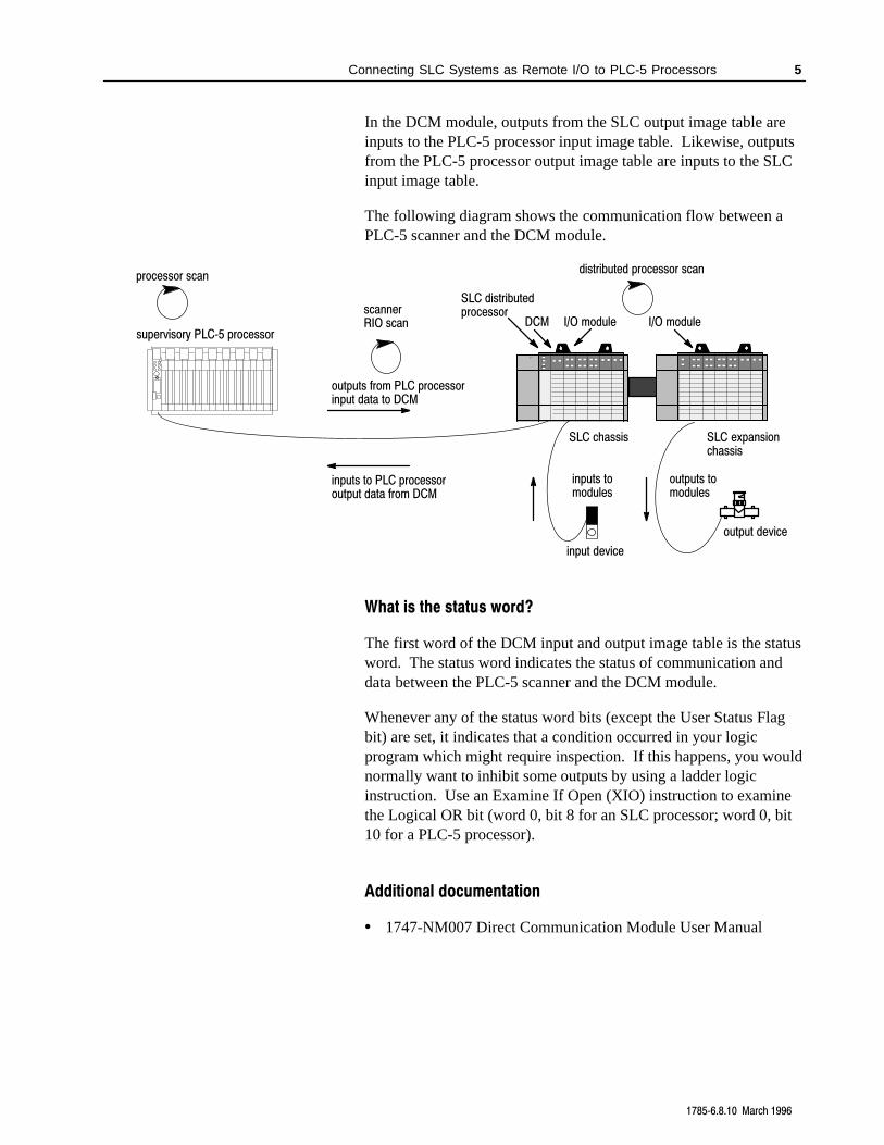
In the DCM module, outputs from the SLC output image table areinputs to the PLC-5 processor input image table. Likewise, outputsfrom the PLC-5 processor output image table are inputs to the SLCinput image table.
The following diagram shows the communication flow between aPLC-5 scanner and the DCM module.
SLC distributedprocessor
processor scan
supervisory PLC5 processor
scannerRIO scan
outputs from PLC processorinput data to DCM
inputs to PLC processoroutput data from DCM
DCM I/O module
distributed processor scan
SLC chassis
I/O module
SLC expansionchassis
inputs tomodules
outputs tomodules
input device
output device
What is the status word?
The first word of the DCM input and output image table is the statusword. The status word indicates the status of communication anddata between the PLC-5 scanner and the DCM module.
Whenever any of the status word bits (except the User Status Flagbit) are set, it indicates that a condition occurred in your logicprogram which might require inspection. If this happens, you wouldnormally want to inhibit some outputs by using a ladder logicinstruction. Use an Examine If Open (XIO) instruction to examinethe Logical OR bit (word 0, bit 8 for an SLC processor; word 0, bit10 for a PLC-5 processor).
Additional documentation
• 1747-NM007 Direct Communication Module User Manual
Connecting SLC Systems as Remote I/O to PLC-5 Processors 6
17856.8.10 March 1996
ADAPTERCOMM FAULT
1747-ASB
1 2
34
56
78
SW
1
1 2
34
56
78
SW
2
1 2
34
56
78
SW
3
ONON
LINE 1
SHLD
LINE 2
NC
IN
RET
(MSB)
LOGICAL RACK
(LSB)
LOGICAL GROUP
BAUDRATE
PRI/COMP
RSV
(MSB)
(LSB)
IMAGESIZE
HLS
PRL
RESP
LAST CHA
ADDRMODE
SP MODE
KEY
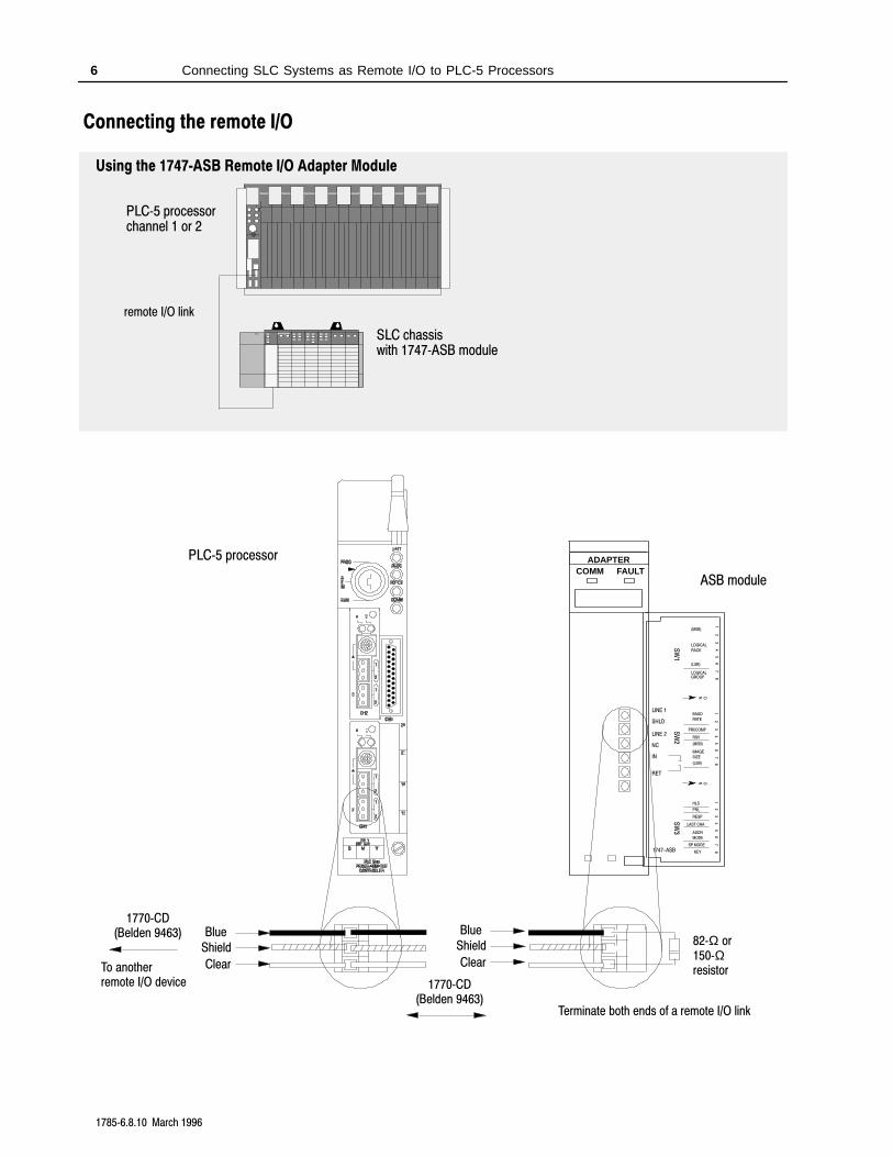
Using the 1747ASB Remote I/O Adapter Module
PLC5 processorchannel 1 or 2
remote I/O link
SLC chassiswith 1747ASB module
ASB module
PLC5 processor
To anotherremote I/O device
1770CD(Belden 9463)
Clear
ShieldBlue
82Ω or150Ωresistor
Clear
ShieldBlue
Terminate both ends of a remote I/O link
1770CD(Belden 9463)
Connecting the remote I/O
Connecting SLC Systems as Remote I/O to PLC-5 Processors 7
17856.8.10 March 1996
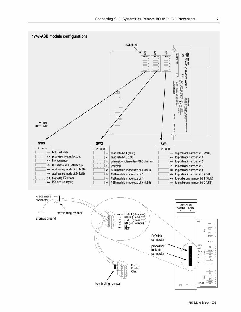
1747ASB module configurations
1 ON
24
56
78
3
SW1SW2SW3
logical rack number bit 5 (MSB)
logical rack number bit 4
logical rack number bit 3
logical rack number bit 2
logical rack number bit 1
logical rack number bit 0 (LSB)
logical group number bit 1 (MSB)
logical group number bit 0 (LSB)
1 ON
24
56
78
3
baud rate bit 1 (MSB)
baud rate bit 0 (LSB)
primary/complementary SLC chassis
reserved
ASB module image size bit 3 (MSB)
ASB module image size bit 2
ASB module image size bit 1
ASB module image size bit 0 (LSB)
1 ON
24
56
78
3
hold last state
processor restart lockout
link response
last chassis/PLC3 backup
addressing mode bit 1 (MSB)
addressing mode bit 0 (LSB)
specialty I/O mode
I/O module keying
SL
C 500
CA
TS
ER
SE
RIA
L NO
.F
RN
U
L
SA
switches
1 2
34
56
78
SW
1
ON
1 2
34
56
78
SW
2
ON
1 2
34
56
78
SW
3
ON
IMP
OR
TAN
T:IN
STA
LL IN S
LOT
ZE
RO
OF
MO
DU
LAR
CH
AS
SIS
ON
LYR
EM
OT
E I/O
AD
AP
TE
R M
OD
UL
E
FAC
1MM
AD
E IN
US
A
CU
RR
EN
T R
EQ
UIR
EM
EN
T: 375mA
LIST
ED
IND
. CO
NT. E
Q.
FO
R H
AZ
. LOC
. A196
CLA
SS
1, GR
OU
PS
A, B
, C A
ND
D, D
IV. 2
OP
ER
AT
ING
TE
MP
ER
AT
UR
E
CO
DE
T3C
ON
OFF
ADAPTERCOMM FAULT
1747-ASB
RIO linkconnector
1 2
34
56
78
SW
1
1 2
34
56
78
SW
2
1 2
34
56
78
SW
3
ONON
LINE 1
SHLD
LINE 2
NC
IN
RET
(MSB)
LOGICAL RACK
(LSB)
LOGICAL GROUP
BAUDRATE
PRI/COMP
RSV
(MSB)
(LSB)
IMAGESIZE
HLS
PRL
RESP
LAST CHA
ADDRMODE
SP MODE
KEYterminating resistor
terminating resistor
to scanner'sconnector
chassis groundLINE 1 (Blue wire)SHLD (Shield wire)LINE 2 (Clear wire)NC (No Connect)INRET
Blue
ClearShield
processorlockoutconnector
Connecting SLC Systems as Remote I/O to PLC-5 Processors 8
17856.8.10 March 1996
Use 1770-CD (or Belden 9463) cable. Connect a remote I/Onetwork using a daisy-chain configuration.
The maximum cable length for remote I/O depends on thetransmission rate. Configure all devices on a remote I/O link tocommunicate at the same transmission rate.
A remote I/O link using thiscommunication rate:
Cannot exceed thiscable length:
57.6 kbps 3,048 m (10,000 ft)
115.2 kbps 1,524 m (5,000 ft)
230.4 kbps 762 m (2,500 ft)
Installing a 1747ASB module
The total number of adapters allowed on a remote I/O link are:
• 32 if the scanner and all adapters on the remote I/O link haveextended node capability
• 16 if the scanner or any adapter does not have extended nodecapability
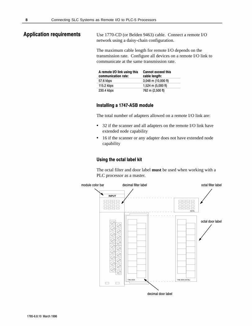
Using the octal label kit
The octal filter and door label must be used when working with aPLC processor as a master.
INPUT
1746-XXXX 1746-XXXX (OCTAL)
OCTAL
octal door label
octal filter label
decimal door label
decimal filter labelmodule color bar
Application requirements
Connecting SLC Systems as Remote I/O to PLC-5 Processors 9
17856.8.10 March 1996
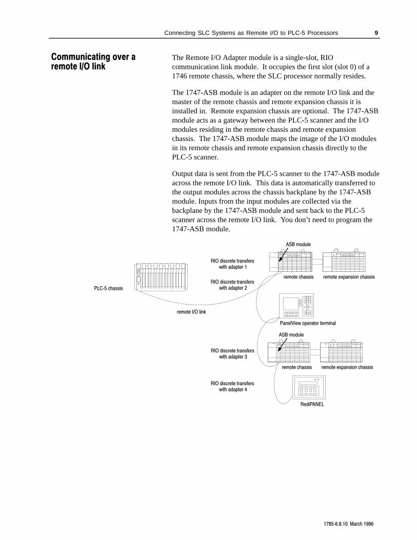
The Remote I/O Adapter module is a single-slot, RIOcommunication link module. It occupies the first slot (slot 0) of a1746 remote chassis, where the SLC processor normally resides.
The 1747-ASB module is an adapter on the remote I/O link and themaster of the remote chassis and remote expansion chassis it isinstalled in. Remote expansion chassis are optional. The 1747-ASBmodule acts as a gateway between the PLC-5 scanner and the I/Omodules residing in the remote chassis and remote expansionchassis. The 1747-ASB module maps the image of the I/O modulesin its remote chassis and remote expansion chassis directly to thePLC-5 scanner.
Output data is sent from the PLC-5 scanner to the 1747-ASB moduleacross the remote I/O link. This data is automatically transferred tothe output modules across the chassis backplane by the 1747-ASBmodule. Inputs from the input modules are collected via thebackplane by the 1747-ASB module and sent back to the PLC-5scanner across the remote I/O link. You don’t need to program the1747-ASB module.
RediPANEL
PanelView operator terminal
remote I/O link
PLC5 chassis
ASB module
remote chassis remote expansion chassis
ASB module
remote chassis remote expansion chassis
RIO discrete transfers with adapter 1
RIO discrete transfers with adapter 2
RIO discrete transfers with adapter 3
RIO discrete transfers with adapter 4
Communicating over aremote I/O link
Connecting SLC Systems as Remote I/O to PLC-5 Processors 10
17856.8.10 March 1996
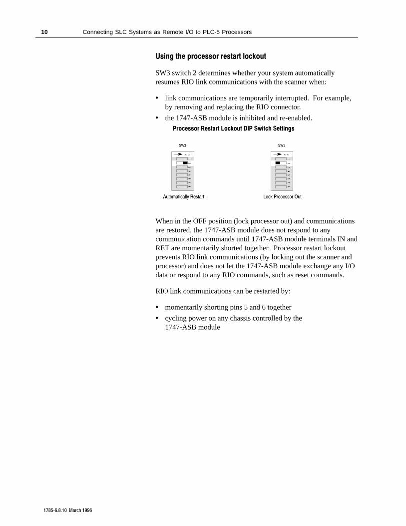
Using the processor restart lockout
SW3 switch 2 determines whether your system automaticallyresumes RIO link communications with the scanner when:
• link communications are temporarily interrupted. For example,by removing and replacing the RIO connector.
• the 1747-ASB module is inhibited and re-enabled.
SW3
Lock Processor Out
41
23
56
78
ON
Processor Restart Lockout DIP Switch Settings
SW3
Automatically Restart
41
23
56
78
ON
When in the OFF position (lock processor out) and communicationsare restored, the 1747-ASB module does not respond to anycommunication commands until 1747-ASB module terminals IN andRET are momentarily shorted together. Processor restart lockoutprevents RIO link communications (by locking out the scanner andprocessor) and does not let the 1747-ASB module exchange any I/Odata or respond to any RIO commands, such as reset commands.
RIO link communications can be restarted by:
• momentarily shorting pins 5 and 6 together
• cycling power on any chassis controlled by the1747-ASB module
Connecting SLC Systems as Remote I/O to PLC-5 Processors 11
17856.8.10 March 1996
While in the ON position, the 1747-ASB module always attempts torestart communications with the scanner if RIO link communicationsare interrupted or if the 1747-ASB module is inhibited andre-enabled. While in the ON position, the 1747-ASB module doesnot respond if terminals 5 and 6 are shorted together.
The 1747-ASB module is shipped from the factory with the defaultposition ON (automatic restart).
!ATTENTION: Cycling power on any chassisremoves the processor restart lockout condition.
Additional documentation
• 1747-6.13 Remote I/O Adapter Module User Manual
Connecting SLC Systems as Remote I/O to PLC-5 Processors 12
17856.8.10 March 1996
SCANNER
1 2NO
COMM FAULT
SW1
CONNECT ONE END OFCABLE SHIELD TO CHASSISMOUNTING BOLT. REFER TO
USER'S MANUAL.
1747-SN
LINE 1
LINE 2
SHIELD
1 2 KBAUD
ON
OFF
OFF OFF
OFF
ON
ON
ON
57.6
115.2
230.4
230.4
√
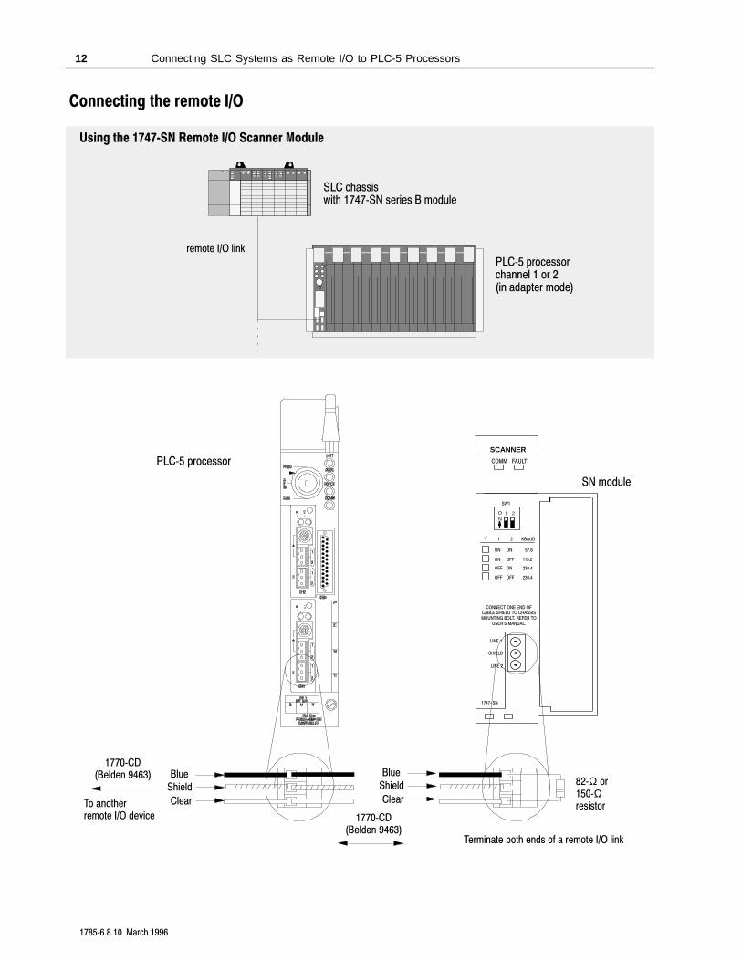
Using the 1747SN Remote I/O Scanner Module
PLC5 processorchannel 1 or 2(in adapter mode)
remote I/O link
SLC chassiswith 1747SN series B module
SN module
PLC5 processor
To anotherremote I/O device
1770CD(Belden 9463)
Clear
ShieldBlue
82Ω or150Ωresistor
Clear
ShieldBlue
Terminate both ends of a remote I/O link
1770CD(Belden 9463)
Connecting the remote I/O
Connecting SLC Systems as Remote I/O to PLC-5 Processors 13
17856.8.10 March 1996
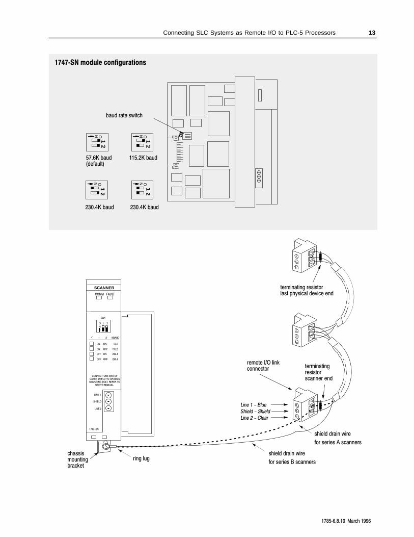
1747SN module configurations
Line 1 - Blue
Line 2 - Clear
chassismountingbracket
remote I/O linkconnector
terminating resistorlast physical device end
terminatingresistorscanner end
Shield - Shield
shield drain wire
for series A scanners
ring lug
SCANNER
1 2NO
COMM FAULT
SW1
CONNECT ONE END OFCABLE SHIELD TO CHASSISMOUNTING BOLT. REFER TO
USER'S MANUAL.
1747-SN
LINE 1
LINE 2
SHIELD
1 2 KBAUD
ON
OFF
OFF OFF
OFF
ON
ON
ON
57.6
115.2
230.4
230.4
√
baud rate switch
57.6K baud(default)
115.2K baud
230.4K baud 230.4K baud
12
N O
12
N O
12
N O
12
N O
shield drain wire
for series B scanners
Connecting SLC Systems as Remote I/O to PLC-5 Processors 14
17856.8.10 March 1996
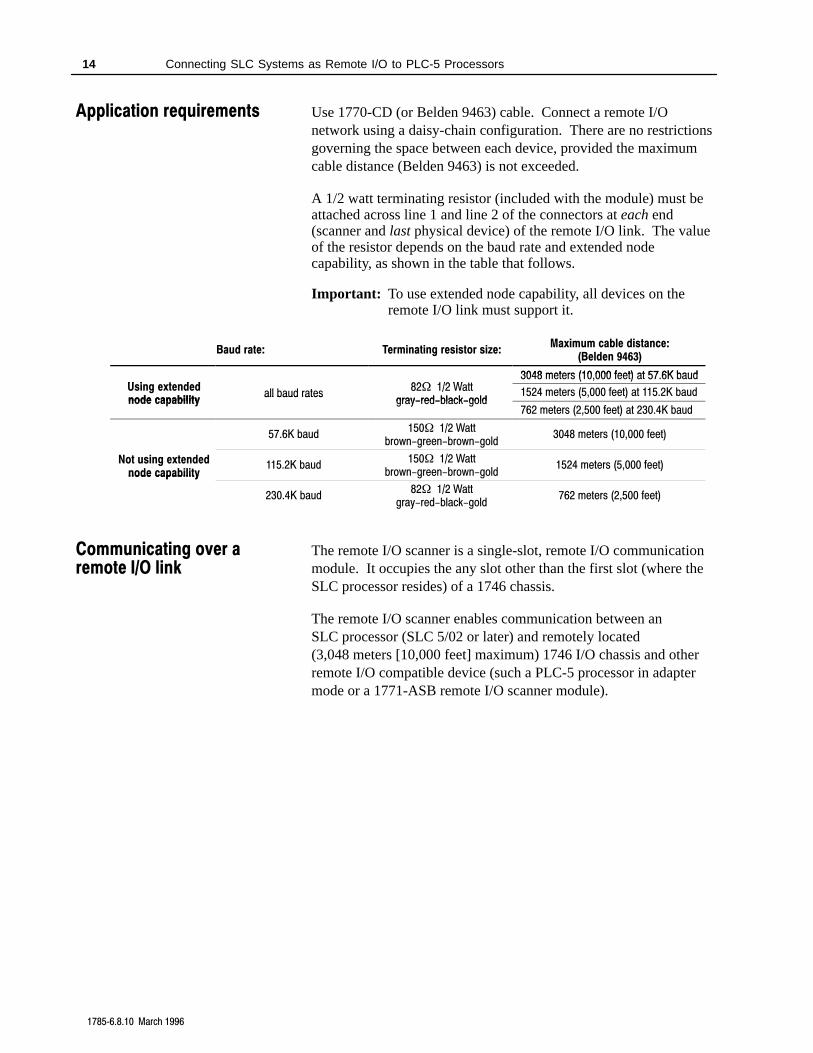
Use 1770-CD (or Belden 9463) cable. Connect a remote I/Onetwork using a daisy-chain configuration. There are no restrictionsgoverning the space between each device, provided the maximumcable distance (Belden 9463) is not exceeded.
A 1/2 watt terminating resistor (included with the module) must beattached across line 1 and line 2 of the connectors at each end(scanner and last physical device) of the remote I/O link. The valueof the resistor depends on the baud rate and extended nodecapability, as shown in the table that follows.
Important: To use extended node capability, all devices on theremote I/O link must support it.
Baud rate: Terminating resistor size:Maximum cable distance:
(Belden 9463)
3048 meters (10 000 feet) at 57 6K baudU i t d d 82 1/2 W tt
3048 meters (10,000 feet) at 57.6K baudUsing extendednode capability
all baud rates82 1/2 Watt
gray-red-black-gold1524 meters (5,000 feet) at 115.2K baud
node capabilityall baud rates
gray-red-black-gold762 meters (2,500 feet) at 230.4K baud
57.6K baud150 1/2 Watt
brown-green-brown-gold3048 meters (10,000 feet)
Not using extendednode capability
115.2K baud150 1/2 Watt
brown-green-brown-gold1524 meters (5,000 feet)
node capability
230.4K baud82 1/2 Watt
gray-red-black-gold762 meters (2,500 feet)
The remote I/O scanner is a single-slot, remote I/O communicationmodule. It occupies the any slot other than the first slot (where theSLC processor resides) of a 1746 chassis.
The remote I/O scanner enables communication between anSLC processor (SLC 5/02 or later) and remotely located(3,048 meters [10,000 feet] maximum) 1746 I/O chassis and otherremote I/O compatible device (such a PLC-5 processor in adaptermode or a 1771-ASB remote I/O scanner module).
Application requirements
Communicating over aremote I/O link
Connecting SLC Systems as Remote I/O to PLC-5 Processors 15
17856.8.10 March 1996
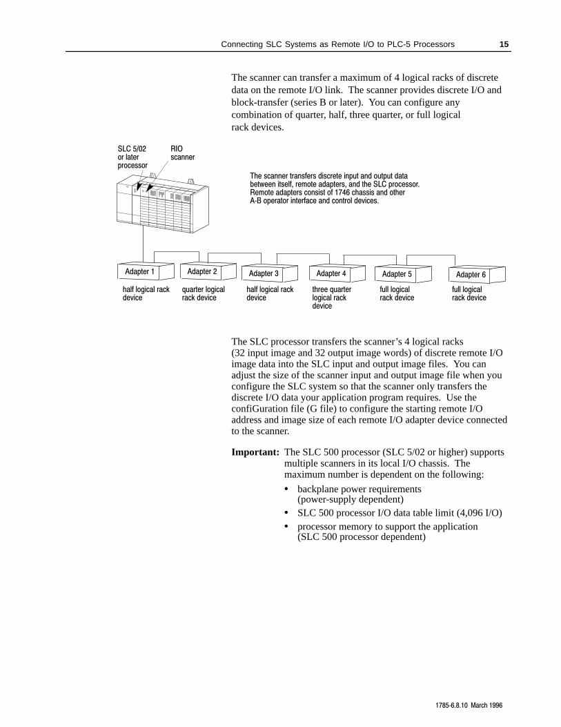
The scanner can transfer a maximum of 4 logical racks of discretedata on the remote I/O link. The scanner provides discrete I/O andblock-transfer (series B or later). You can configure anycombination of quarter, half, three quarter, or full logicalrack devices.
The scanner transfers discrete input and output databetween itself, remote adapters, and the SLC processor.Remote adapters consist of 1746 chassis and otherAB operator interface and control devices.
RIOscanner
SLC 5/02or laterprocessor
quarter logicalrack device
half logical rackdevice
three quarterlogical rackdevice
full logicalrack device
half logical rackdevice
full logicalrack device
Adapter 1 Adapter 2 Adapter 3 Adapter 4 Adapter 5 Adapter 6
The SLC processor transfers the scanner’s 4 logical racks(32 input image and 32 output image words) of discrete remote I/Oimage data into the SLC input and output image files. You canadjust the size of the scanner input and output image file when youconfigure the SLC system so that the scanner only transfers thediscrete I/O data your application program requires. Use theconfiGuration file (G file) to configure the starting remote I/Oaddress and image size of each remote I/O adapter device connectedto the scanner.
Important: The SLC 500 processor (SLC 5/02 or higher) supportsmultiple scanners in its local I/O chassis. Themaximum number is dependent on the following:
• backplane power requirements(power-supply dependent)
• SLC 500 processor I/O data table limit (4,096 I/O)• processor memory to support the application
(SLC 500 processor dependent)
Connecting SLC Systems as Remote I/O to PLC-5 Processors 16
17856.8.10 March 1996
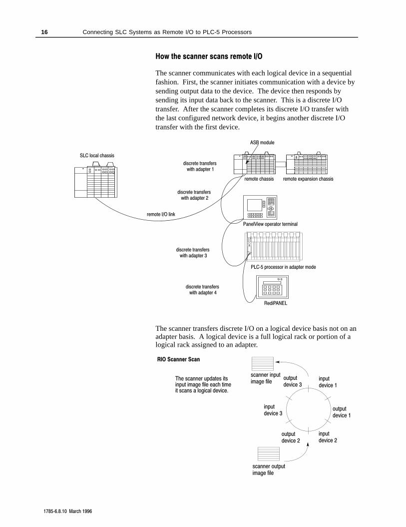
How the scanner scans remote I/O
The scanner communicates with each logical device in a sequentialfashion. First, the scanner initiates communication with a device bysending output data to the device. The device then responds bysending its input data back to the scanner. This is a discrete I/Otransfer. After the scanner completes its discrete I/O transfer withthe last configured network device, it begins another discrete I/Otransfer with the first device.
RediPANEL
PanelView operator terminal
remote I/O link
SLC local chassis
ASB module
remote chassis remote expansion chassis
PLC5 processor in adapter mode
discrete transfers with adapter 1
discrete transfers with adapter 2
discrete transfers with adapter 3
discrete transfers with adapter 4
The scanner transfers discrete I/O on a logical device basis not on anadapter basis. A logical device is a full logical rack or portion of alogical rack assigned to an adapter.
RIO Scanner Scan
scanner outputimage file
The scanner updates itsinput image file each timeit scans a logical device.
outputdevice 3
outputdevice 2
outputdevice 1
inputdevice 3
inputdevice 2
inputdevice 1
scanner inputimage file
Connecting SLC Systems as Remote I/O to PLC-5 Processors 17
17856.8.10 March 1996
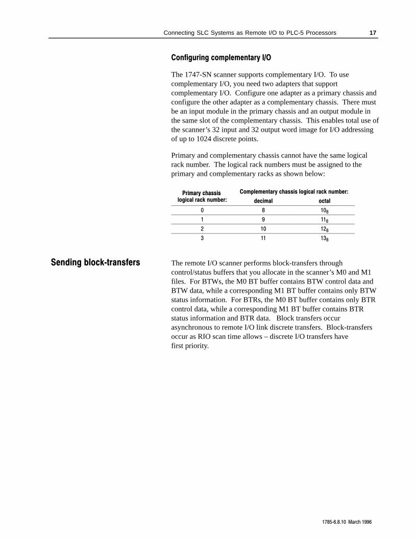
Configuring complementary I/O
The 1747-SN scanner supports complementary I/O. To usecomplementary I/O, you need two adapters that supportcomplementary I/O. Configure one adapter as a primary chassis andconfigure the other adapter as a complementary chassis. There mustbe an input module in the primary chassis and an output module inthe same slot of the complementary chassis. This enables total use ofthe scanner’s 32 input and 32 output word image for I/O addressingof up to 1024 discrete points.
Primary and complementary chassis cannot have the same logicalrack number. The logical rack numbers must be assigned to theprimary and complementary racks as shown below:
Primary chassis Complementary chassis logical rack number:Primary chassis logical rack number: decimal octal
0 8 108
1 9 118
2 10 128
3 11 138
The remote I/O scanner performs block-transfers throughcontrol/status buffers that you allocate in the scanner’s M0 and M1files. For BTWs, the M0 BT buffer contains BTW control data andBTW data, while a corresponding M1 BT buffer contains only BTWstatus information. For BTRs, the M0 BT buffer contains only BTRcontrol data, while a corresponding M1 BT buffer contains BTRstatus information and BTR data. Block transfers occurasynchronous to remote I/O link discrete transfers. Block-transfersoccur as RIO scan time allows – discrete I/O transfers havefirst priority.
Sending blocktransfers
Connecting SLC Systems as Remote I/O to PLC-5 Processors 18
17856.8.10 March 1996
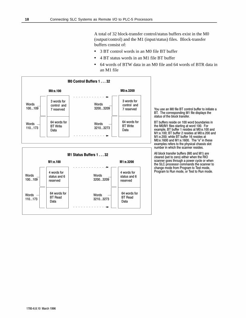
A total of 32 block-transfer control/status buffers exist in the M0(output/control) and the M1 (input/status) files. Block-transferbuffers consist of:
• 3 BT control words in an M0 file BT buffer
• 4 BT status words in an M1 file BT buffer
• 64 words of BTW data in an M0 file and 64 words of BTR data inan M1 file
You use an M0 file BT control buffer to initiate aBT. The corresponding M1 file displays thestatus of the block transfer.
BT buffers reside on 100 word boundaries inthe M0/M1 files starting at word 100. Forexample, BT buffer 1 resides at M0:e.100 andM1:e.100; BT buffer 2 resides at M0:e.200 andM1:e.200; while BT buffer 16 resides atM0:e.1600 and M1:e.1600. The e" in theseexamples refers to the physical chassis slotnumber in which the scanner resides.
All block transfer buffers (M0 and M1) arecleared (set to zero) either when the RIOscanner goes through a power cycle or whenthe SLC processor commands the scanner tochange mode from Program to Test mode,Program to Run mode, or Test to Run mode.
M0:e.100
Words100...109
3 words forcontrol and7 reserved
64 words forBT WriteData
M1:e.100
4 words for status and 6reserved
64 words forBT ReadData
M0:e.3200
Words3200...3209
3 words forcontrol and7 reserved
64 words forBT WriteData
M1:e.3200
4 words for status and 6reserved
64 words forBT ReadData
M0 Control Buffers 1 . . . 32
M1 Status Buffers 1 . . . 32
Words110...173
Words3210...3273
Words100...109
Words3200...3209
Words110...173
Words3210...3273
Connecting SLC Systems as Remote I/O to PLC-5 Processors 19
17856.8.10 March 1996
Application considerations when using blocktransfers
Below are points to consider when implementingblock-transfer operations:
• The minimum amount of scanner image that can be assigned to adevice on the RIO link is 1/4 logical rack in the G fileconfiguration. This allows up to four separate devices per logicalrack. Each device could have a maximum of four block-transfersconfigured to it. Thus, up to 16 BTRs and/or 16 BTWs could beassigned to each logical rack.
• If a block-transfer device is a 1747-ASB remote I/O adapter, thenmultiple SLC 500 modules (such as analog modules) could bescanned by the 1747-ASB and the data block transferred to the1747-SN scanner. Since the remote I/O network handles oneblock-transfer request per logical rack at a time, there will be adelay before all devices in the 1747-ASB rack can be accessed.
• Inhibiting a device on the remote I/O network (via control wordsM0:e.8...11) precludes that device from block-transfer operations.Trying to initiate a block-transfer to an inhibited device results inan error reply. The scanner cancels a block-transfer that is inprogress if it detects that the device is inhibited. Because of theasynchronous nature of inhibiting a device that has ablock-transfer in progress, the reply may indicate either asuccessful completion or an error. In either case, the SLC controlprogram must still clear the Enable flag.
• All M0 and M1 BT buffers are cleared (set to all zeros) after apower cycle and when the SLC processor goes from Program toRun mode, Program to Test mode, or Test to Run mode.
When using complementary I/O, if you configure a complementarydevice to use more I/O image space than an associated primarydevice, then block-transfers can only be performed to locations in thecomplementary device that have associated I/O image space in theprimary device. For example, if a primary device is 1/2 logical rackand a complementary device is a full logical rack, block-transferscan be performed only in the first 1/2 logical rack of thecomplementary device.
Connecting SLC Systems as Remote I/O to PLC-5 Processors 20
17856.8.10 March 1996
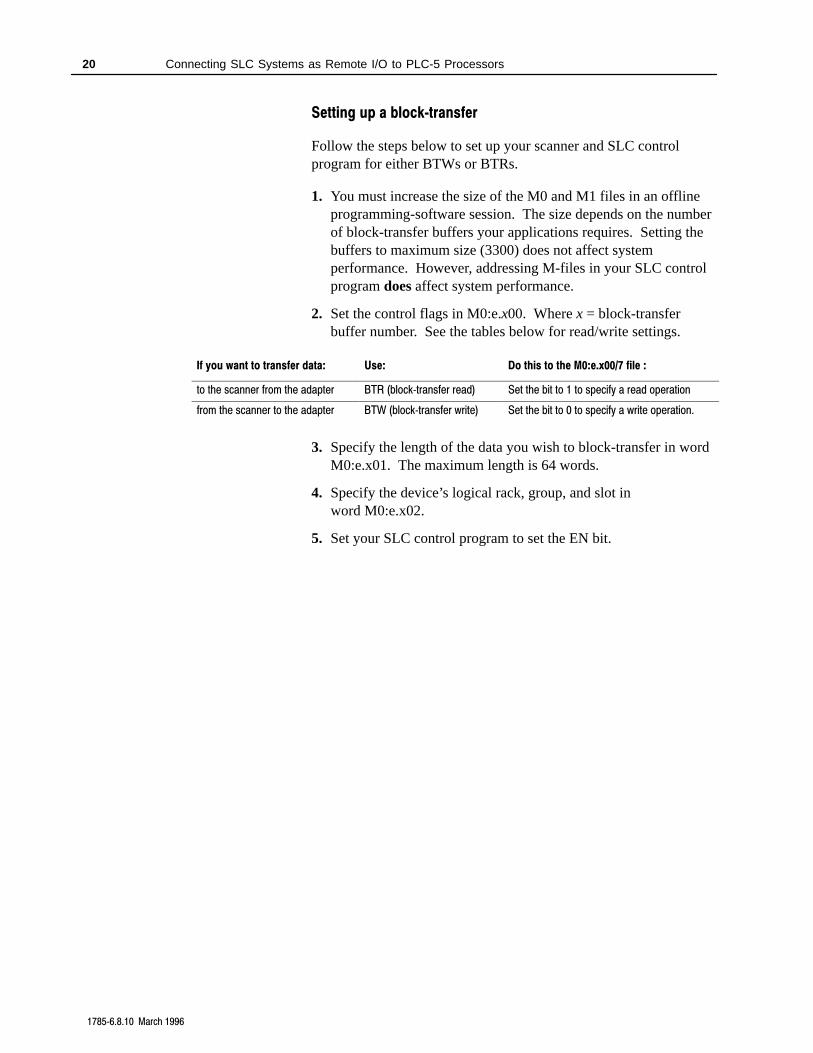
Setting up a blocktransfer
Follow the steps below to set up your scanner and SLC controlprogram for either BTWs or BTRs.
1. You must increase the size of the M0 and M1 files in an offlineprogramming-software session. The size depends on the numberof block-transfer buffers your applications requires. Setting thebuffers to maximum size (3300) does not affect systemperformance. However, addressing M-files in your SLC controlprogram does affect system performance.
2. Set the control flags in M0:e.x00. Where x = block-transferbuffer number. See the tables below for read/write settings.
If you want to transfer data: Use: Do this to the M0:e.x00/7 file :
to the scanner from the adapter BTR (blocktransfer read) Set the bit to 1 to specify a read operation
from the scanner to the adapter BTW (blocktransfer write) Set the bit to 0 to specify a write operation.
3. Specify the length of the data you wish to block-transfer in wordM0:e.x01. The maximum length is 64 words.
4. Specify the device’s logical rack, group, and slot inword M0:e.x02.
5. Set your SLC control program to set the EN bit.
Connecting SLC Systems as Remote I/O to PLC-5 Processors 21
17856.8.10 March 1996
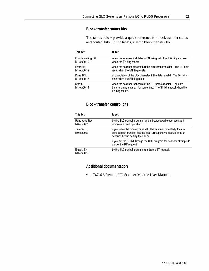
Blocktransfer status bits
The tables below provide a quick reference for block transfer statusand control bits. In the tables, x = the block transfer file.
This bit: Is set:
Enable waiting EWM1:e.x00/10
when the scanner first detects EN being set. The EW bit gets resetwhen the EN flag resets.
Error ERM1:e.x00/12
when the scanner detects that the block transfer failed. The ER bit isreset when the EN flag resets.
Done DNM1:e.x00/13
at completion of the block transfer, if the data is valid. The DN bit isreset when the EN flag resets.
Start STM1:e.x00/14
when the scanner schedules" the BT for the adapter. The datatransfers may not start for some time. The ST bit is reset when theEN flag resets.
Blocktransfer control bits
This bit: Is set:
Readwrite RWM0:e.x00/7
by the SLC control program. A 0 indicates a write operation; a 1indicates a read operation.
Timeout TOM0:e.x00/8
if you leave the timeout bit reset. The scanner repeatedly tries tosend a blocktransfer request to an unresponsive module for fourseconds before setting the ER bit.
if you set the TO bit through the SLC program the scanner attempts tocancel the BT request.
Enable ENM0:e.x00/15
by the SLC control program to initiate a BT request.
Additional documentation
• 1747-6.6 Remote I/O Scanner Module User Manual
1
PLC, PLC-2, PLC-5, SLC, SLC 5/02, SLC 5/03, and SLC 5/04 are trademarks of Allen-Bradley Company, Inc.
AllenBradley, a Rockwell Automation Business, has been helping its customers improveproductivity and quality for more than 90 years. We design, manufacture and support a broadrange of automation products worldwide. They include logic processors, power and motioncontrol devices, operator interfaces, sensors and a variety of software. Rockwell is one of theworlds leading technology companies.
Worldwide representation.
Argentina • Australia • Austria • Bahrain • Belgium • Brazil • Bulgaria • Canada • Chile • China, PRC • Colombia • Costa Rica • Croatia • Cyprus • Czech Republic •Denmark • Ecuador • Egypt • El Salvador • Finland • France • Germany • Greece • Guatemala • Honduras • Hong Kong • Hungary • Iceland • India • Indonesia •
Ireland • Israel • Italy • Jamaica • Japan • Jordan • Korea • Kuwait • Lebanon • Malaysia • Mexico • Netherlands • New Zealand • Norway • Pakistan • Peru •Philippines • Poland • Portugal • Puerto Rico • Qatar • Romania • Russia-CIS • Saudi Arabia • Singapore • Slovakia • Slovenia • South Africa, Republic • Spain •Sweden • Switzerland • Taiwan • Thailand • Turkey • United Arab Emirates • United Kingdom • United States • Uruguay • Venezuela • Yugoslavia
AllenBradley Headquarters, 1201 South Second Street, Milwaukee, WI 53204 USA, Tel: (1) 414 3822000 Fax: (1) 414 3824444
17856.8.10 March 1996 95512411Copyright 1996 AllenBradley Company, Inc. Printed in USA