Embed Size (px)
Citation preview

Americas Headquarters:Cisco Systems, Inc., 170 West Tasman Drive, San Jose, CA 95134-1706 USA
Connecting DSL WAN Interface Cards
Revised: November 2011, OL-12846-04
This document describes how to connect Cisco DSL WAN interface cards. For an overview of Cisco interface cards used for Cisco access routers, see Overview of Cisco Interface Cards for Cisco Access Routers. For descriptions of interface cards see “Related Documentation” section on page 17.
ADSL WICs Asymmetric digital subscriber line WAN interface cards (ADSL WICs) are available in the following variations:
• WIC-1ADSL-DG
• WIC-1ADSL-I-DG
Front Panel on ADSL WICsADSL WICs have three LEDs, as shown in Figure 1, and described in Table 5.
Note Front panel labels may differ with model numbers.

Connecting DSL WAN Interface Cards ADSL High Speed WICs
2
Figure 1 ADSL and G.SHDSL WIC Front Panels
ADSL High Speed WICsHigh speed ADSL WICs are available in the following variations:
• ADSL over plain old telephone service (ADSLoPOTS) high-speed WAN interface cards (HWICs)
– HWIC-ADSL—a 1-port ADSLoPOTS card
– HWIC-ADSL-B/ST—a 2-port card with a port for ADSLoPOTS and a data-only backup port for an ISDN BRI S/T connection
• ADSL over ISDN (ADSLoISDN) HWICs
– HWIC-ADSLI—a 1-port ADSLoISDN card
– HWIC-ADSLI-B/ST—a 2-port card with a port for ADSLoISDN and a data-only backup port for an ISDN BRI S/T connection
Note ADSL HWICs can be inserted only in those interface slots that are enabled to receive HWICs. To determine which slots in your router are enabled to receive HWICs, see Overview of Cisco Interface Cards for Cisco Access Routers.
ADSL HWICs are all packaged in the Cisco standard single-wide HWIC form factor.
Front Panel on ADSL HWICsADSL HWICs have three LEDs. Those ADSL HWICs with a backup ISDN port have three additional LEDs.
Figure 2 shows the front panels and LEDs for the ADSLoPOTS and ADSLoISDN HWICs. The LED descriptions are listed in Table 5.
Figure 2 ADSLoPOTS HWIC Front Panel
SEE MANUAL BEFORE INSTALLATION
WIC1ADSL
CD LP OKADSLADSL
2547
53
1271
17
ADSL
LPCDOK
SEE MANUAL BEFORE
INSTALLATION
B1B2OK
SEE MANUAL BEFORE
INSTALLATION
RJ-11 Connector RJ-11 Connector
LEDs
RJ-45 Connector
ADSL
LPCDOK
ISDN BRI S/T
LEDsLEDs

Connecting DSL WAN Interface Cards G.SHDSL WICs
3Connecting DSL WAN Interface Cards
G.SHDSL WICsG.SDSL WICs are available in the following variations:
• WIC-1SHDSL
• WIC-1SHDSL-V2 and WIC-1SHDSL-V3
Caution To comply with the Telcordia GR-1089 NEBS standard for electromagnetic compatibility and safety, connect the 1-port G.SHDSL interface card (WIC-1SHDSL-V2 and WIC-1SHDSL-V3) only to intra-building or non-exposed wiring or cabling. The intrabuilding cable must be shielded and the shield must be grounded at both ends.
Front Panel on G.SHDSL WICsThe ADSL and G.SHDSL WICs have three LEDs shown in Figure 3 and described in Table 5.
Note Front panel labels may differ with model numbers.
Figure 3 G.SHDSL WIC Front Panels
G.SHDSL High Speed WICsHigh speed WICs are available in the following variations:
• G.SHDSL HWICs
– HWIC-2SHDSL
– HWIC-4SHDSL
• G.SHDSL EFM
– HWIC-4SHDSL-E
Note Inverse multiplexing over ATM (IMA) lines and ATM segmentation and reassembly (SAR) lines are not supported on the G.SHDSL EFM HWIC.
Note The HWIC-4SHDSL-E provides four DSL pairs of connectivity through one RJ-45 connector.
SEE MANUAL BEFORE INSTALLATION
WIC1ADSL
CD LP OKADSLADSL
2547
53

Connecting DSL WAN Interface Cards Multimode VDSL2/ADSL2/2+ HWICs
4
Note The Cisco HWIC-2SHDSL and the Cisco HWIC-4SHDSL-E provide support for the Dying Gasp feature; however, the Cisco HWIC-4SHDSL does not provide support for this feature. The term dying gasp refers to power status as defined in ITU-T standard G.991.2, section 7.1.2.5.3.
Front Panel on G.SHDSL HWICsThe G.SHDSL HWICS have three or five LEDs as shown in Figure 4 and Figure 5 and described in Table 5.
Note Front panel labels may differ with model numbers.
Figure 4 HWIC-2SHDSL Front Pane
Figure 5 HWIC-4SHDSL-E Front Panel
Multimode VDSL2/ADSL2/2+ HWICsMultimode VDSL2/ADSL2/2+ HWICs are available in the following variations:
• ADSL/VDSL over POTS
– EHWIC-VA-DSL-A, Annex A
– EHWIC-VA-DSL-M, Annex M
• ADSL/VDSL over ISDN
– EHWIC-VA-DSL-B, Annex B
Note Multimode VDSL2/ADSL2/2+ HWICs can be inserted only in those interface slots that are enabled to receive EHWICs. To determine which slots in your router are enabled to receive HWICs, see the Interface Card Slot Locations and Numbering on Cisco Access Routers section of Overview of Cisco Interface Cards for Cisco Access Routers.
1555
62
SHDSL
GRWIC2SHDSL EN L0 L1
SEE MANUALBEFORE INSTALLATION
2532
15
SHDSL
RJ45 CONNECTOR ONLYEN/LP
L0 L1 L2 L3
SEE MANUAL BEFOREINSTALLATION
HWIC4SHDSL-E

Connecting DSL WAN Interface Cards G.SHDSL High Speed EHWICs
5Connecting DSL WAN Interface Cards
Front Panel on Multimode VDSL2/ADSL2/2+ HWICsThe Multimode VDSL2/ADSL2/2+ HWICs have three LEDS as shown in Figure 6 and described in Table 5.
Note Front panel labels may differ with model numbers.
Figure 6 Multimode VDSL2/ADSL2/2+ HWIC Front Panels
G.SHDSL High Speed EHWICsA multimode VDSL2/ADSL2/2+ EHWIC is available, the Cisco EHWIC-4SHDSL-EA (EFM/ATM).
Front Panel on G.SHDSL EFM/ATM EHWICsThe G.SHDSL EFM/ATM HWICs have LEDs that indicate DSL functionality. Figure 7 shows the front panel and LEDs for the EHWIC-4SHDSL-EA. The LED functions are described in Table 5.
Figure 7 Cisco EHWIC-4SHDSL-EA EFM/ATM Faceplate
Note The Cisco EHWIC-4SHDSL-EA provides support for the Dying Gasp feature. The term “dying gasp” refers to power status as defined in ITU-T standard G.991.2, section 7.1.2.5.3.
2543
37
2550
37
SHDSLEHWIC-4SHDSL-EA
EN/LPEFM ATM
SEE MANUAL BEFOREINSTALLATION
RJ45 CONNECTOR ONLY
L3 L2 L1 L0

Connecting DSL WAN Interface Cards Cabling
6
Note G.SHDSL EFM/ATM EHWICs can be inserted only in interface slots that are enabled to receive EHWICs. To determine which slots in your router are enabled to receive HWICs, see the Interface Card Slot Locations and Numbering on Cisco Access Routers section of Overview of Cisco Interface Cards for Cisco Access Routers.
CablingThe twisted-pair straight-through cable for customer premises equipment (CPE) applications is supplied. The RJ-45-to-RJ-45 BRI cable to connect the ISDN BRI ports on ADSL over ISDN HWICs is not supplied. The two-line Y-cable for central office (CO) and four-wire patch panel applications is not supplied. See Overview of Cisco Interface Cards for Cisco Access Routers.
Note The Y-cable must have the wires for pins 3 and 4 twisted together; wires for pins 2 and 5 must also be twisted together. Each pair goes to its own connector at the patch panel end.
Connecting DSL Interface Cards to a Network
Connecting the DSL Ports on WICs and HWICsUse a straight-through RJ-11 cable for this connection.
Table 1 shows the ADSL and VDSL WIC and HWIC pinouts.
Note If you are connecting an ADSL interface card to an RJ-11 wall jack that has the DSL pair wired for pins 2 and 5, you must use an RJ-11 crossover cable (lavender with blue stripe). The RJ-11 crossover cable is orderable separately as a spare.
Table 1 VDSL2/ADSL2/2+ WIC and HWIC Pinouts
Pin Signal
3 Tip
4 Ring

Connecting DSL WAN Interface Cards Connecting DSL Interface Cards to a Network
7Connecting DSL WAN Interface Cards
Table 2 shows the WIC-1SHDSL pinouts.
Table 3 shows the RJ-14C pinouts on the WIC-1SHDSL-V2 and WIC-1SHDSL-V3 interface cards.
To connect a DSL interface card to the WAN, complete the following steps:
Step 1 Confirm that the router is turned off.
Warning To comply with the standard for electromagnetic compatibility and safety, connect the HWIC-ADSLI-B/ST, HWIC-2SHDSL, HWIC-4SHDSL, and HWIC-4SHDSL-E interface cards only to intra-building or unexposed wiring or cable. The intra-building port(s) of the equipment or subassembly must not be metallically connected to interfaces that connect to the OSP or its wiring. These interfaces are designed for use as intra-building interfaces only (Type 2 or Type 4 ports as described in GR-1089-CORE, Issue 4) and require isolation from the exposed OSP cabling. The addition of Primary Protectors is not sufficient protection in order to connect these interfaces metallically to OSP wiring.
Step 2 Connect one end of the cable to the ADSL or G.SHDSL port on the card.
Step 3 Connect the other end to the wall jack (RJ-11) at your site, as shown in Figure 8.
Table 2 WIC-1SHDSL Pinouts
Pin Signal
3 Tip
4 Ring
Table 3 WIC-1SHDSL-V2 RJ-14C Pinouts
Pins Signal Line
3 and 4 3 = Tip, 4 = Ring 0
2 and 5 2 = Tip, 5 = Ring 1

Connecting DSL WAN Interface Cards Connecting DSL Interface Cards to a Network
8
Figure 8 Connecting an ADSL Card to the Wall Jack
Alternatively, when connecting a G.SHDSL card to a 4-wire patch panel, use a Y-cable as shown in Figure 9.
RJ-11wall jack
3770
1
SEE MANUAL BEFORE INSTALLATION
CD LP OK
ADSL port(RJ-11)
ADSL
RJ-11 twisted-pair cable

Connecting DSL WAN Interface Cards Connecting DSL Interface Cards to a Network
9Connecting DSL WAN Interface Cards
Figure 9 Connecting a G.SHDSL Card to a Patch Panel With a Y-Cable
Figure 10Connecting a G.SHDSL EFM Card to a Patch Panel With a Y-Cable
Step 4 Turn on power to the router.
Step 5 To connect the card to the network, you must configure the DSL interface card in the router to the no shutdown state. Enter the no shut command in the router configuration. Verify that the CD LED comes on, indicating that the interface card is connected to the network.
Note This step does not apply to the WIC-1SHDSL-V2, WIC-1SHDSL-V3, and HWIC-4SHDSL-E.
SHDSL
SEE MANUAL BEFORE INSTALLATION
CD LP OK
WIC1SHDSL V2
1032
35
RJ-11twisted-paircables
1413121110
SHDSL port(RJ-11)
Patch panel
2532
29
RJ-45twisted-paircables
SHDSL
RJ45 CONNECTOR ONLY
EN/LP
L0 L1 L2 L3
SEE MANUAL BEFOREINSTALLATION
HWIC4SHDSL-E
SHDSL port(RJ-45)
141312
1110
Patch panel

Connecting DSL WAN Interface Cards Connecting DSL Interface Cards to a Network
10
Connecting the ISDN Ports on HWICsUse an RJ-45-to-RJ-45 BRI cable (not included) to connect the ISDN BRI port to an ISDN NT1 device. See the online document Cisco Modular Access Router Cable Specifications for pinouts.
To connect an ISDN BRI S/T port to the WAN, follow these steps:
Step 1 Confirm that the router is turned off.
Warning To comply with the Telcordia GR-1089 NEBS standard for electromagnetic compatibility and safety, connect the HWIC-ADSL-B/ST or HWIC-ADSLI-B/ST ISDN BRI S/T port only to intra-building or unexposed wiring or cable. The intra-building port(s) of the equipment or subassembly must not be metallically connected to interfaces that connect to the OSP or its wiring. These interfaces are designed for use as intra-building interfaces only (Type 2 or Type 4 ports as described in GR-1089-CORE, Issue 4) and require isolation from the exposed OSP cabling. The addition of Primary Protectors is not sufficient protection in order to connect these interfaces metallically to OSP wiring.
Step 2 Connect one end of a straight-through RJ-45-to-RJ-45 cable to the S/T interface.
Step 3 Connect the other end of the cable to the NT1 device, as shown in Figure 11.
Figure 11 Connecting the BRI S/T Port
Step 4 Connect the NT1 device to the ISDN wall jack according to the documentation that came with the NT1 device.
Step 5 Turn on power to the router.
B1B2OK
SEE MANUAL BEFORE
INSTALLATIONADSL
LPCDOK
ISDN BRI S/T
NT1 device
Straight-throughRJ-45-to-RJ-45cable
BRI S/T port (RJ-45)
S/T port
1274
28
Connecting DSL WAN Interface Cards Connecting DSL Interface Cards to a Network
11Connecting DSL WAN Interface Cards
Connecting the SHDSL Port on the G.SHDSL HWICs and EHWICsConnect Cisco G.SHDSL HWICs as described next:
• Cisco HWIC-2SHDSL—Use a standard RJ-11 straight-through cable to establish connection between the HWIC and a network device.
• Cisco HWIC-4SHDSL, HWIC-4SHDSL EFM, and EHWIC-4SHDSL-EA—Use a standard RJ-45 straight-through cable to establish connection between the HWIC or EHWIC and a network device.
Warning To comply with the Telcordia GR-1089 NEBS standard for electromagnetic compatibility and safety, connect the HWIC-2SHDSL, HWIC-4SHDSL, HWIC-4SHDSL-E interface cards only to intra-building or unexposed wiring or cable. The intra-building port(s) of the equipment or subassembly must not be metallically connected to interfaces that connect to the OSP or its wiring. These interfaces are designed for use as intra-building interfaces only (Type 2 or Type 4 ports as described in GR-1089-CORE, Issue 4) and require isolation from the exposed OSP cabling. The addition of Primary Protectors is not sufficient protection in order to connect these interfaces metallically to OSP wiring.
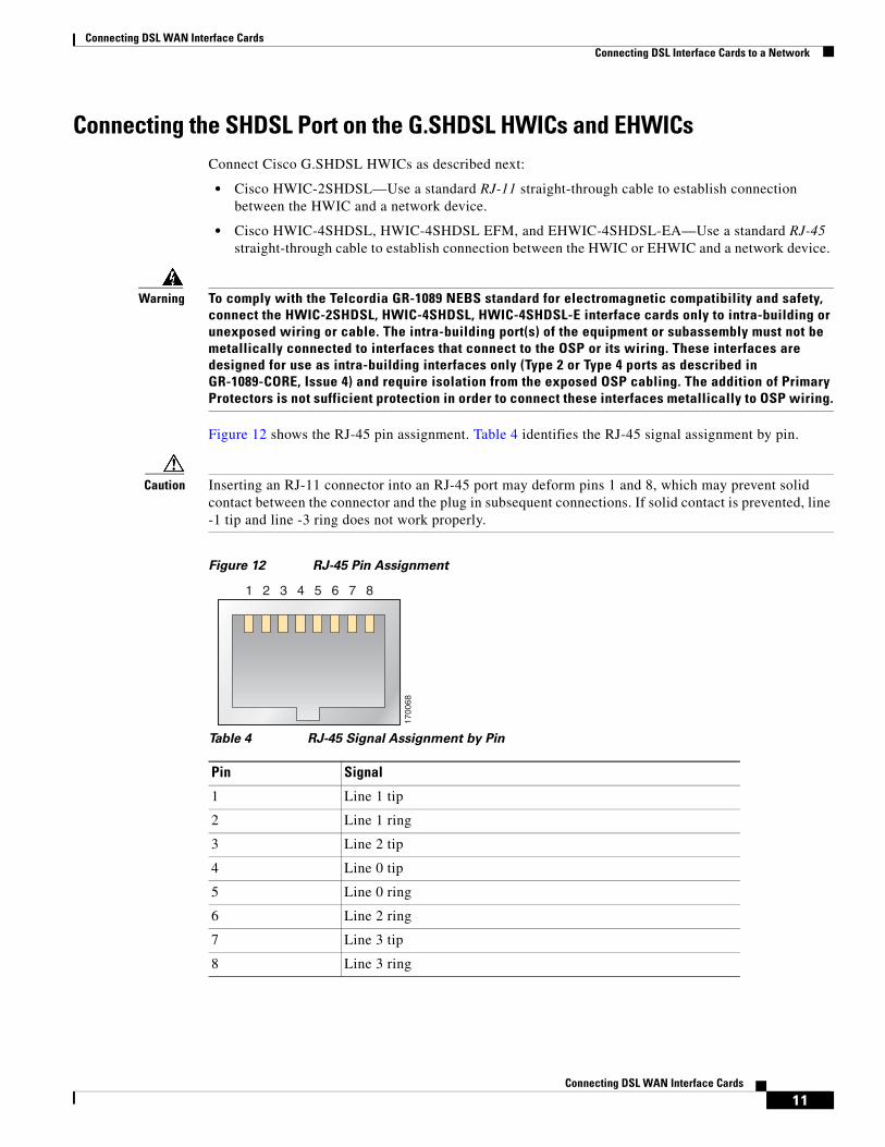
Figure 12 shows the RJ-45 pin assignment. Table 4 identifies the RJ-45 signal assignment by pin.
Caution Inserting an RJ-11 connector into an RJ-45 port may deform pins 1 and 8, which may prevent solid contact between the connector and the plug in subsequent connections. If solid contact is prevented, line -1 tip and line -3 ring does not work properly.
Figure 12 RJ-45 Pin Assignment
1 2 3 4 5 6 7 8
1700
68
Table 4 RJ-45 Signal Assignment by Pin
Pin Signal
1 Line 1 tip
2 Line 1 ring
3 Line 2 tip
4 Line 0 tip
5 Line 0 ring
6 Line 2 ring
7 Line 3 tip
8 Line 3 ring

Connecting DSL WAN Interface Cards Using POTS Splitters and Microfilters with an ADSL-over-POTS WIC (WIC-1ADSL)
12
To connect the Cisco HWIC-4SHDSL or Cisco HWIC-4SHDSL-E with a DSLAM that supports two or four RJ-11 connections, modify the standard RJ-45 cable, using one of the following diagrams as applicable:
• Figure 13 shows how to modify the cable and connect the Cisco HWIC-4SHDSL, HWIC-4SHDSL-E, and EHWIC-4SHDSL-EA with a DSLAM that supports four RJ-11 cable connections. Figure 14 shows how to modify the cable and connect the Cisco HWIC-4SHDSL, HWIC-4SHDSL-E, and EHWIC-4SHDSL-EA with a DSLAM that supports two RJ-11 cable connections.
Figure 13 Standard RJ-45 Connector to Four Standard RJ-11 Connectors
Figure 14 Standard RJ-45 Connector to Two Standard RJ-11 Connectors
Using POTS Splitters and Microfilters with an ADSL-over-POTS WIC (WIC-1ADSL)
POTS splitters and microfilters apply to the ADSL-over-POTS WIC only. They are used on telephone lines to ensure voice- and data-call quality. POTS splitters result in the best data and voice performance when the router and the telephone are used on the same telephone line.
POTS SplittersA POTS splitter is installed on a telephone line connected to both data and voice devices. The splitter routes the data and voice signals on the telephone line to the correct device. Signals intended for the router can disrupt voice calls; signals intended for voice calls can affect router operation.
1555
63
Pin 8Pin 7Pin 6Pin 5Pin 4Pin 3Pin 2Pin 1
Pin 4Pin 3
RJ11 (line 3)
Pin 4Pin 3
RJ11 (line 2)
Pin 4Pin 3
RJ11 (line 0)
Pin 4Pin 3
RJ11 (line 1)
RJ45
1555
64
Pin 8Pin 7Pin 6Pin 5Pin 4Pin 3Pin 2Pin 1
Pin 5Pin 4Pin 3Pin 2
RJ11
Pin 5Pin 4Pin 3Pin 2
RJ11
RJ45

Connecting DSL WAN Interface Cards Using POTS Splitters and Microfilters with an ADSL-over-POTS WIC (WIC-1ADSL)
13Connecting DSL WAN Interface Cards
Most splitters must be installed by the telephone company; however, some splitters can be installed by the customer. If you are not sure what type of splitter to use, contact your service provider.
Figure 15 is an example of a type of POTS splitter that is installed at the customer premises by the customer.
Figure 15 POTS Splitters
MicrofiltersMicrofilters are installed on telephones to improve voice-call quality when voice and data equipment are using the same telephone line (twisted pair). You should use microfilters only when the documentation requires their use.
Figure 16 shows one type of microfilter.
Figure 16 Microfilte
ToCisco router
To wall jack
4119
9
To phone
DATA VOICE
To wall jack
To phone
4120
1
WALL
PHONE

Connecting DSL WAN Interface Cards Using POTS Splitters and Microfilters with an ADSL-over-POTS WIC (WIC-1ADSL)
14
Telephone Company-Installed Splitter
The scenario below describes Figure 17.
• The telephone company has provisioned a single copper pair to be used by both the telephone (POTS) service and the router with a DSL interface card, so a POTS splitter must be installed.
• The splitter is installed by the telephone company on the customer premises. This type of splitter is also referred to as a network interface device (NID).
• The router and telephone are on separate lines (twisted pair) to the splitter.
• The router and telephone share the same telephone line (twisted pair) to the telephone company.
Figure 17 Telephone Company-Installed Splitter
Customer-Installed Splitter
The scenario below describes Figure 18.
• The telephone company has provisioned a single copper pair used by the telephone (POTS) service and the router with a DSL interface card, so a POTS splitter must be installed.
• The splitter is installed by the customer on the customer premises.
• The router and telephone are directly connected to the splitter connected to the telephone line.
• The router and telephone share the same telephone line (twisted pair) to the telephone company.
• For optional telephones connected through the splitter, microfilters are optional. They should be installed only if they improve telephone call quality.
• For telephones connected directly to the telephone line, microfilters are required.
Splitter (NID)To telco
Cisco router
Optionalmicrofilters
3919
6
Actual wall of building

Connecting DSL WAN Interface Cards Supported Platforms
15Connecting DSL WAN Interface Cards
Figure 18 Customer-Installed Splitter
Router and Telephone Using Separate Telephone Lines
The scenario below describes Figure 19.
• The telephone company has provisioned a single copper pair to be used exclusively by the router with a DSL interface card and a separate copper pair to be used exclusively by the telephone (POTS) service; therefore, neither a POTS splitter nor a microfilter is needed.
• The microfilter is optional; it should be installed only if it improves telephone call quality.
Figure 19 No Splitter, Optional Microfilter
Supported PlatformsFor a list of the platforms supported by a Cisco interface card, see Platform Support for Cisco Interface Cards.
Splitter
To telco
Optional telephones,if supported by your telco
Required microfilter
Actual wall of building
3927
5
Cisco router
Optionalmicrofilters
Optional microfilter
Line 1to telco (ADSLor G.SHDSL)
Line 2to telco (POTS)
Actual wall of building
3919
7
Cisco router

Connecting DSL WAN Interface Cards Interface Card LEDs
16
Finding Support Information for Platforms and Cisco IOS Software Images
Use Cisco Feature Navigator to find information about platform support and Cisco IOS software image support. Access Cisco Feature Navigator at http://www.cisco.com/go/fn. You must have an account on Cisco.com. If you do not have an account or have forgotten your username or password, click Cancel at the login dialog box and follow the instructions that appear.
Interface Card LEDs
Table 5 DSL Interface Card LEDs
LED Color Description
CD LED Green Lit when the unit is connected to the network and operating normally. On ADSL interface cards only, this LED blinks while training with DSLAMs. Does not apply to the WIC-1SHDSL-V2 or WIC-1SHDSL-V3 interface cards.
LP LED Yellow DSL interface is in loopback mode.
Off Normal operation.
OK LED Green Enabled when the card is detected by the router.
LINK (CD) LED
Green and Yellow
Green when cells or frames are passing between the host and the DSLAM. Yellow when the T1E1 framer detects an alarm. Applies only to the WIC-1SHDSL-V2 and WIC-1SHDSL-V3 interface cards.
EN Green Operating system is running.
Amber Interface card is resetting.
Blinking System is initializing.
L0, L1, L2, L3, L4, L5, L6, L7
Status of link:
On—Link is active.
Off—Link is inactive (disabled).
Blinking—Link is training / Link alarm.
Amber and green blinking simultaneously—Loopback mode. EN/LP is also amber (HWIC-4SHDSL-E and EHWIC-2SHDSL-EA).
EN/LP Green Operating system is running.
Amber Loopback mode.
EFM Green EFM mode.
ATM Green ATM mode.
OK (ADSL)
Green Enabled when the card is detected by the router. This LED blinks while downloading firmware.
B1 Green ISDN port. Blinks with active connection on the first B channel.
B2 Green ISDN port. Blinks with active connection on the second B channel.
OK (ISDN)
Green ISDN port has established a connection with the central office switch (D channel).

Connecting DSL WAN Interface Cards Related Documentation
17Connecting DSL WAN Interface Cards
Related DocumentationRelated documentation is available on Cisco.com. For more information, see the “Obtaining Documentation, Obtaining Support, and Security Guidelines” section on page 17.
Interface Card General Information
– Cisco Router—Guide For teleworkers, small offices, small to medium-sized businesses and enterprise branch and head offices
– Overview of Cisco Interface Cards for Cisco Access Routers
Feature Modules
– Configuring Cisco Multimode G.SHDSL EFM/ATM in Cisco ISR G2
– Configuring Cisco G.SHDSL EFM HWICs in Cisco Access Routers
– Configuring Cisco G.SHDSL HWICs in Cisco Access Routers
– 1-Port ADSL WAN Interface Card for Cisco 2600 Series and Cisco 3600 Series Routers, Cisco IOS Release 12.2(4)T
– 1-Port ADSL WAN Interface Card, Cisco IOS Releases 12.1(3)XJ and 12.2(2)T
– 1-Port ADSL WAN Interface Card, Cisco IOS Release 12.1(5)YB
– ATM Mode for Two-Wire or Four-Wire SHDSL, Cisco IOS Release 12.3(7)T
– T1/E1 Mode for SHDSL, Cisco IOS Release 12.3(7)T
– Enhanced Voice and QoS for ADSL and G.SHDSL, Cisco IOS Release 12.3(2)T
Sample Configurations
– Configuring PPP over Ethernet with NAT
– Configuring PPP over ATM with NAT
– Configuring a LAN with DHCP and VLANs
– Configuring a VPN Using Easy VPN and an IPSec Tunnel
Obtaining Documentation, Obtaining Support, and Security Guidelines
For information on obtaining documentation, obtaining support, providing documentation feedback, security guidelines, and also recommended aliases and general Cisco documents, see the monthly What’s New in Cisco Product Documentation, which also lists all new and revised Cisco technical documentation, at:
http://www.cisco.com/en/US/docs/general/whatsnew/whatsnew.html
Cisco and the Cisco logo are trademarks or registered trademarks of Cisco and/or its affiliates in the U.S. and other countries. To view a list of Cisco trademarks, go to this URL: www.cisco.com/go/trademarks. Third-party trademarks mentioned are the property of their respective owners. The use of the word partner does not imply a partnership relationship between Cisco and any other company. (1110R)
Any Internet Protocol (IP) addresses used in this document are not intended to be actual addresses. Any examples, command display output, and figures included in the document are shown for illustrative purposes only. Any use of actual IP addresses in illustrative content is unintentional and coincidental.
© 2011 Cisco Systems, Inc. All rights reserved.

Connecting DSL WAN Interface Cards Obtaining Documentation, Obtaining Support, and Security Guidelines
18


![James Burton, Albert Lee, Amos Garrett, David Wilcox - Guitar Heroes [CD/LP Liner Notes]](https://img.pdfslide.us/doc/110x75/55cf8f4c550346703b9aeae8/james-burton-albert-lee-amos-garrett-david-wilcox-guitar-heroes-cdlp.jpg)