Embed Size (px)
Citation preview

CONNECTICUT YANKEE ATOMIC POWER COMPANY
HADDAM NECK PLANT362 INJUN HOLLOW ROAD * EAST HAMPTON, CT 06424-3099
JAN - 9 2007Docket No. 50-213
CY-07-004
Re: 10 CFR 50.82
U. S. Nuclear Regulatory CommissionAttention: Document Control DeskWashington, DC 20555-0001
Haddam Neck PlantRevised Groundwater Monitorinq Plan to Support HNP License Termination and
Radioloqical Groundwater Monitorin-QProcedures..
In a letter dated September 22, 2006,(1) Connecticut Yankee Atomic Power Company(CYAPCO) submitted Revision 1 to the Groundwater Monitoring Plan-for the Haddam NeckPlant (HNP) site that incorporated responses to NRC comments. The purpose of thissubmittal is to provide Revision 2 of the Plan, which was revised to provide clarification andupdate references to revised groundwater monitoring procedures. Only the revised textand tables are provided (Attachment 1), as there are no proposed changes to the figuresand appendices provided in Revision 1.
A copyý of the revised:prodedures is also included with this submittal (Attachment 2).
There are no regulat6ry commnitments contained in this submittal.
CYAPCO hereby requests the NRC review and concur with the revised GroundwaterMonitoring Plan for the HNP site. If you shouldohave any questions regarding thissubmittal,, please contact me .at (860) 267-3938.
(1) G.P. van Noordennen (CYAPCO) letter to US NRC, "Response to NRC Staff
Comments/Questions On Groundwater Monitoring Plan to Support HNP LicenseTermination", dated September 22, 2006.
C)

NRC Document Control DeskCY-07-004/Page 2
Sincerely,
G. P. van Noordennen DateDirector, Nuclear Safety and Regulatory Affairs
Attachment 1: Groundwater Monitoring Plan to Support HNP License Termination Plan,January 2007, Rev. 2
Attachment 2: Radiological Groundwater Monitoring Procedure Set, November 2006
cc: S. J. Collins, Region I AdministratorM. Roberts, Acting Chief, Decommissioning and Laboratory Branch, NRC Region IJ. Peckenpaugh, USNRC HeadquartersT. B. Smith, Project Manager, Haddam Neck PlantE. L. Wilds, Jr., Director, CT DEP Radiation DivisionP. Hill, CT DEP Remediation Division

CY-07-004
Attachment 1
Groundwater Monitoring Plan to Support HNP License Termination Plan, Rev. 2(Text and Tables, only)

Groundwater Monitoring Plan toSupport HNP License Termination
Connecticut Yankee Atomic PowerCompany
Haddam Neck Plant
January 2007
Rev. 2
REV.2 18-MONTH GWMP

Table of Contents
1.0 Purpose ............................................................................................................................. 12.0 Scope and O bjectives ................................................................................................ 2
2 .1 S co p e ......................................................................................................................... 22.2 O bjectives .......................................................................................................... 3
3.0 Groundwater Monitoring Requirements .............................................................. 43.1 Summary Overview of HNP Hydrogeologic Conceptual Model ................ 5
3.1.1 Contaminant Distribution in Groundwater .......................................... 83.2 Groundwater Monitoring Well Network ....................................................... 9
3.2.1 Monitoring Well Locations and Rationale ............................................ 93.3 Groundwater Sampling and Analysis Requirements .................................. 11
3.3.1 Target A nalytes ....................................................................................... 113.3.2 Target Analyte Closure Criteria ............................................................ 12
3.4 Quality Assurance Requirements .................................................................. 123.5 Groundwater Monitoring Deliverables .......................................................... 12
4.0 Monitoring Plan Implementation Schedule ........................................................ 14
List of Tables
Table 3-1 Monitoring Well Parameters
Table 3-2 Monitoring Well Network and Well Characteristics
Table 3-3 Target Radionuclides and Detection Limits
Table 3-4 The Criteria and Performance Defined to meet Closure RequirementAcceptance at the end of the 18-month Clock for License Termination
Table 4-1 18-Month License Termination Groundwater Monitoring Schedule
List of Figures
Figure 2-1 Haddam Neck Plant Property Map
Figure 3-1 Inferred water elevation contours in shallow unconfined aquifer, HaddamNeck Plant, 17 August 2005.
Figure 3-2 Inferred water elevation contours in shallow unconfined aquifer, HaddamNeck Plant, 11 September 2005.
Figure 3-3 Inferred water elevation contours in shallow unconfined aquifer, HaddamNeck Plant, 5 December 2005
Figure 3-4 Areas of Significant Contaminant Releases and Soil Remediation
Figure 3-5 Shallow Groundwater Flow Paths as Affected by Underground Structures
Figure 3-6 Conceptual Groundwater Flow Patterns in Fractured Bedrock
REV.2 18-MONTH GWMP

Figure 3-7 Aerial Photo of the Haddam Neck Plant Showing Exposed Bedrock Underthe Former Primary Auxiliary Building, Waste Disposal Building and TankFarm AreasFigure 3-8 Forward Particle Tracking from Two Rows of ArbitraryPoints During Post-Demo Conditions Under Average Annual Recharge
Figure 3-9 Reverse Particle Tracking from Major Monitoring Wells in Steady StateOperational Mode
Figure 3-10
Figure 3-11
Figure 3-12
Figure 3-13
Figure 3-14
Figure 3-15
Figure 3-16
Figure 3-17
Figure 3-18
Figure 3-19
Figure 3-20
Inferred Distribution of the Unfiltered Tritium (pCi/L) in the unconsolidateddeposits hydrostratigraphic unit at the industrial area and upper peninsulaarea of the Haddam Neck Plant December 2003
Inferred Distribution of the filtered Tritium (pCi/L) in the shallow bedrockhydrostratigraphic unit at the industrial area and upper peninsula area of theHaddam Neck Plant December 2003
Inferred Distribution of Tritium (pCi/L) in the unconfined aquifer at theindustrial area and upper peninsula area of the Haddam Neck Plant June2005
Inferred Distribution of Tritium (pCi/L) in the confined aquifer at theindustrial area and upper peninsula area of the Haddam Neck Plant June2005
Inferred Distribution of filtered Tritium (pCi/L) in the deep bedrockhydrostratigraphic unit at the industrial area and upper peninsula area of theHaddam Neck Plant December 2003
Inferred Distribution of Sr-90 (pCi/L) in the unconfined aquifer at theindustrial area and upper peninsula area of the Haddam Neck Plant June2005
Inferred Distribution of Sr-90 (pCi/L) in the confined aquifer at the industrialarea and upper peninsula area of the Haddam Neck Plant June 2005
Monitoring Well Locations
Cross Section Traces A-A' and B-B'
Cross Section A-A' Inferred Vertical Tritium Plume Distribution
Cross Section B-B' Inferred Vertical Tritium Plume Distribution
List of Attachments
Attachment 1 Monitoring Well Construction Diagrams
Attachment 2 Monthly On-site Precipitation Totals for August 2002 through December2005
REV. 218-MONTH GWMP 11

1.0 Purpose
The purpose of this groundwater monitoring plan is to define the requirements for verifyingthat groundwater contamination conditions at Connecticut Yankee Atomic PowerCompany's (CYAPCO) Haddam Neck Plant (HNP) meet the closure requirements asdefined in the License Termination Plan (LTP) (Haddam Neck Plant License TerminationPlan). The LTP specifies a minimum 18-month period of groundwater monitoring (toinclude two spring/high water seasons) to verify the efficacy of remedial actions at thefacility. The monitoring period will begin following completion of remedial actionsconducted with the use of groundwater depression systems. The groundwater monitoringprogram is required to demonstrate that groundwater contaminant conditions are below theestablished LTP closure criteria (a maximum dose rate of 25 mrem/yr for all exposurepathways, and conformance to the Derived Concentration Guideline Level, or DCGL) andexhibit either stable or decreasing trends.
This document describes the groundwater monitoring plan that will be implemented tosupport license termination at the HNP. The following sections describe the elements of theplan:
* Scope and Objectives
* Groundwater Monitoring Plan Requirements
* Groundwater Monitoring Well Network
* Groundwater Sampling and Analysis Requirements
* Quality Assurance
" Groundwater Monitoring Plan Implementation Schedule and Deliverables
A separate groundwater monitoring plan will be developed implemented to demonstratecompliance with the State of Connecticut Department of Environmental Protection (CTDEP)Remediation Standards Regulation (RSR) Criteria in order to reach site closure under theProperty Transfer Program.
REV.2 18-MONTH GWMP 1

2.0 Scope and Objectives
The scope and objectives of the groundwater monitoring plan for license termination aredescribed in this section.
2.1 ScopeThe scope of this groundwater monitoring plan is confined to the portion of the HaddamNeck Plant site that either has historically exhibited plant-related groundwatercontamination or may potentially exhibit plant-related groundwater contaminationfollowing decommissioning of plant facilities. The Haddam Neck Plant site is divided intothe following functional areas (see Figure 2-1):
* The Industrial Area and Upper Peninsula. This portion of the site includes theformer power reactor and generating station facilities, cooling water facilities, relatedwaste processing and treatment facilities, former spent and new fuel storagefacilities, maintenance shops, warehouses, and administrative facilities. Thesefacilities occupied the major portion of the developed part of the site, including theupper (i.e., plant northern) part of the peninsula that separates the cooling waterdischarge canal from the Connecticut River. This portion of the plant has historicallyexhibited plant-related groundwater contamination by radioactive constituents andis the primary focus of this groundwater monitoring plan.
* The Parking Lot and Emergency Operations Facility. This portion of the siteincludes the primary parking area, former warehouses, the storm-water retentionpond, and the former Emergency Operations Facility (EOF). No radioactive plant-related constituent release areas are located in this generally upgradient portion ofthe plant. Some selected wells in this area, however, will be monitored under thisgroundwater monitoring plan to ensure that contaminant plumes are bounded.
* The Lower Peninsula. The lower (plant southern) part of the peninsula between thedischarge canal and the Connecticut River. The lower peninsula has exhibited verylow-level, discontinuous detections of plant-related radionuclides in the northern-most portion. One well, MW-117, will be monitored under this plan to ensure thatclosure criteria are not exceeded in this area.
The functional areas of HNP identified below are not subject to the 18-month licensetermination groundwater monitoring activity:
The Independent Spent Fuel Storage Installation (ISFSI). The ISFSI includes thespent fuel storage area and associated support facilities, and some former ancillaryactivity areas (i.e., the former shooting range and a bulky waste disposal area).These areas have been approved for release from the license and are no longer partof the request for release.
REV. 2 18-MONTH GWMP 2

The Undeveloped Area of the Site ("Backlands"). The backlands include the balanceof the HNP property not described above and is the majority of the total land area.Although some surface effect from historical stack releases may have occurred, thebacklands are located upgradient from the HNP and no apparent potential forgroundwater contamination is identified. These areas have also been approved forrelease from the license.
2.2 ObjectivesThe objectives of this plan are two-fold:
1) to define a process by which groundwater radiological contamination conditions atHNP will be measured and documented during the monitoring period required forlicense termination; and
2) to provide a structure for groundwater monitoring activities that will ensure that theprocess is implemented appropriately and that the information generated will verifythat groundwater conditions meet the specified LP closure conditions.
REV. 2 18-MONTH GWMP 3

3.0 Groundwater Monitoring Requirements
Several conditions are identified in the LTP as precursors to starting the 18-monthgroundwater monitoring activity. These conditions are identified below:
* Complete the development of a groundwater model and conduct particle trackingunder a variety of scenarios,
* Identify and finalize monitoring well locations and install monitoring wells,
" Allow areas on site where groundwater had been suppressed to recharge to seasonalnorms,
* Complete remediation, backfill, and radiologic assessment activities in the TankFarm area, and any other radiological remediation needed below the watertableareas requiring the use of a groundwater depression system.
As an additional enhancement in support of groundwater sampling, CYAPCO will requiresa minimum of five days between termination of monitoring well development activities andinitiation of groundwater sampling for all newly installed monitoring wells.
These precursors have been completed and monitoring well locations have been finalized,all wells are installed, developed and the waiting equilibration period expired prior toinitiation of sampling the newly constructed monitoring wells. Remediation of the TankFarm area is complete, and backfill and final radiological assessment activities have beencompleted in December 2005, and the area has been backfilled.
The groundwater table in the soil and bedrock remediation areas has recharged to seasonalnorms. Active dewatering to support deep soil remediation and structure demolition wasdiscontinued in August 2005. This included termination of operation of the containmentfoundation mat dewatering sump, which had operated almost continually throughout theHNP operation. Nine monitoring wells were selected for weekly water level measurementto assess water level recovery and include:
* MW-101S,* MW-102S,* MW-131S,* MW-130,* MW-508D,* MW-109S,* MW-106S,* MW-107S, and* MW-110S.
In addition, the water level in the mat sump was measured weekly to evaluate recovery.The observed water levels in these wells were contoured using a commercial datacontouring software (SurferTM) and the resulting water level elevation contours were plotted
REV. 2 18-MONTH GWMP 4

over a site map indicating the well locations, location of remaining subsurface structures,and soil removal areas.
The contoured water elevations for 17 August 2005 revealed the expected groundwaterdepression in the central industrial area, immediately after stopping dewatering activities.The water level recovered to seasonal norms within 30 days of termination of dewatering, asindicated by the water elevation contours for 11 September 2005, and continued to rise asrainfall increased during September and October (as shown in Attachment 2). Water levelcontour maps for the unconfined aquifer in August, September, and December are shown inFigures 3-1, 3-2, and 3-3, respectively. At this time, no residual effects of dewatering areobservable on the groundwater levels at the site. Data-logging pressure transducers will bemaintained in the nine monitoring wells used for this assessment during the 18-monthmonitoring period to evaluate long-term water level changes. The Connecticut River gagestation is located in the discharge canal south of the HNP, and the location is shown onFigure 2-1. Should the river gage station become inoperable, the United States GeologicalSurvey (USGS) River gage stations at Middletown, Connecticut, can be used to calculate theriver stage at HNP. Synoptic water level measurements will be taken coincident with eachgroundwater sample event, as a minimum.
Following completion of the precursor activities, the 18-month groundwater monitoring hascommenced. The requirements for groundwater monitoring in support of licensetermination are described in this section. The general categories of requirements are asfollows:
* Groundwater monitoring well network;
* Groundwater sampling and analysis requirements;
* Quality Assurance Requirements; and
" Data Reporting Requirements and Deliverables.
These topics are discussed in the following subsections.
In support of the 18-month Groundwater Monitoring Plan, a summary of the hydrogeologicconceptual model for the HNP site and the contaminant distribution in groundwater areprovided in Section 3.1 below.
3.1 Summary Overview of HNP Hydrogeologic ConceptualModelA hydrogeologic Conceptual Site Model (CSM) was developed for the HNP based on boththe regional geologic setting and hydrogeologic and chemical data collected at the site(CH2M HILL, 2005). The hydrogeologic CSM developed for the HNP describes a complex,leaky, multi-unit aquifer system exhibiting hydraulic interconnection between the perched,unconfined, and confined aquifers as delineated at the facility. Groundwater occurs underunconfined, semi-confined, and confined conditions in the subsurface at the HNP.
A localized perched aquifer consisting of wetland fluvial deposits and fill material issituated beneath the parking lot area (Figure 2-1). An organic silt layer that extends
REV. 2 18-MONTH GWMP 5

throughout the outline of this former wetland exhibits aquitard properties and serves as animpermeable flow barrier, allowing the perched water table to exist. Plant-relatedradionuclides have not been detected in the perched aquifer.
The water table or unconfined aquifer beneath HNP consists of the unconsolidatedsediments interconnected with shallow weathered and/or intensely fractured bedrock. Thisaquifer system exhibits porous media flow characteristics. Groundwater flow propertieswithin the native sediments are essentially the same regardless of lithology and grain size.
The confined aquifer beneath HNP consists of a complex network of interconnectedfractures in crystalline bedrock that were developed in response to local and tectonicstresses. The crystalline rock matrix has negligible effective porosity or permeability;therefore, groundwater flow in the bedrock is controlled by the secondary porosity andpermeability developed within the fractures. The geometric distribution and openness, oraperture, of individual fractures controls groundwater flow and contaminant migration.Bedrock characterization data indicate groundwater flows beneath the HNP mainly alongsub- vertical fractures, which are generally along strike of the foliation trends, and alongsub- horizontal fractures associated with glacial unloading.
Groundwater in both the unconfined and confined aquifers flows southerly across the sitetowards the Connecticut River (Figure 3-3). The Connecticut River is the dischargeboundary for both surface water and groundwater for the entire watershed, acting as thedefinitive endpoint for groundwater flow paths in the hydrogeologic CSM for the HNP.
The distribution of groundwater contamination at the HNP site has been monitored over thelast several years by means of a quarterly sampling program. As of June 2005, thismonitoring program has shown that detectable concentrations of tritium and Sr-90 arepresent in site groundwater, but significant levels of Co-60 and Cs-137 have not beenobserved, especially in more recent years. This observation is consistent with the site-specific partition coefficients (Kds) determined for radionuclides at HNP. The partitioncoefficients control the distribution of the radionuclides in groundwater as compounds withlow Kd values are strongly partitioned to groundwater relative to soil and geologic material,while compounds with higher Kd values are more readily partitioned to the solid phase.Tritium has a Kd value of zero and Sr-90 has the lowest Kd (i.e. 8mL/g) of the remainingradionuclides at the site. Thus, the presence of tritium and Sr-90 in site groundwater isconsistent with the site-specific Kds determined for Sr-90, Co-60, and Cs-137.
The lower Kd for tritium relative to Sr-90 has resulted in tritium migrating into the deeper,confined aquifer at the HNP site. Detection of Sr-90 in groundwater is generally limited tothe shallow, unconfined aquifer.
Source areas at HNP are described by two types: 1) Primary Release Areas,, wherecontaminants, consisting largely of dissolved radionuclides in aqueous coolant and otherprocess solutions, were released to the ground under various circumstances; and 2)Secondary Source Areas, consisting of surface and subsurface soil that was subsequentlycontaminated by the primary releases, either immediately on release, or due todowngradient migration of contaminants in. groundwater. Secondary sources containedcontaminants at concentrations above soil screening concentrations and could causegroundwater to exceed closure criteria in the future. The primary release and secondary
REV. 2 18-MONTH GWMP 6

source areas were remediated during demolition activities. The primary release areas forsignificant releases of radioactive materials and secondary source areas are shown in Figure3-4.
Groundwater at HNP flows from the inland areas toward the Connecticut River in agenerally north to south direction (Figure 3-3). The Connecticut River forms the dischargeboundary for surface water as well as shallow and deep groundwater at HNP.Groundwater flow paths have been identified through observations of water elevation inmultiple wells, and the flow paths have been simulated using the groundwater flow modelfor HNP (STRATEX LLC, 2005). Details of the hydrogeologic conceptual site model havebeen described previously (CH2M HILL, 2005). The general groundwater features aredescribed below.
Within the near-surface portion of the unconfined aquifer, the groundwater flow is divertedby plant structures that intercept the bedrock/ unconsolidated interface and extend toelevations above, or near to, the water table. These structures built onto/into bedrockinclude the following that will remain after demolition:
* The reactor containment building (RCB) foundation and walls;
• The spent fuel pool foundation;
* The foundation walls beneath the plant-north portion of the former service building;
* The discharge tunnels; and
• The B-switchgear building foundation.
Historically, other structures would have diverted shallow groundwater, creatingpreferential flow pathways; these include the Primary Auxiliary Building (PAB), the wastedisposal building, the ion exchange building, and the spent resin facility. These structureswere removed in their entirety during plant demolition. The diversion of shallowgroundwater around these impediments to flow is illustrated in Figure 3-5.
Bedrock structural features (e.g., fracture sets and contacts between differing rock types)create preferential flow paths within the deeper bedrock. Of particular interest is a linearfeature, believed to consist primarily of a near-vertical fracture set, in combination withintersecting near-horizontal fracture sets, that demonstrates connectivity (through hydraulicresponse during packer testing deep bedrock wells) extending from well MW-121A near theConnecticut River, to wells the MW-103 well cluster, within the former wastewater tankfarm area. The general direction of groundwater flow in the deep bedrock (i.e., belowstructural interference) is illustrated in Figure 3-6. Figure 3-6 also illustrates the variabilityin flow patterns inherent to fractured rock systems. Areas of elevated hydraulicconductivity have been observed and inferred along structural features aligned with therock foliation. These consist primarily of near-vertical fracture sets, rock foliation andcontact zones. Secondary features exhibiting lower hydraulic conductivity include near-horizontal fracture sets at various elevations in the rock, as well as secondary mineralcontacts (e.g., pegmatite dikes) that intersect the other features. Figure 3-7 is an aerialphotograph of HNP that illustrates the exposed bedrock features in the former PABfootprint. Note the strong linear features aligned with the general north-south trending
REV. 2 18-MONTH GWMP 7

foliation. Also apparent are discontinuous pegmatite dikes that cross and sometimes alignwith the foliation.
The characteristic groundwater flow beneath the plant with ultimate discharge into theConnecticut River is illustrated in Figure 3-8 which presents simulated particle track flowpaths from releases in the inland portion of the industrial area under post-closure hydraulicconditions (i.e., no dewatering, no mat sump operation, demolition in final configuration).Figure 3-9 illustrates a slightly different approach to flow path simulations. This figureshows reverse particle tracks (i.e., particles flowing backward from the river toward theinland portion of the industrial area) under historical operating conditions. In this scenario,the high conductivity preferential flow paths in bedrock appear to play a major role ingroundwater flow direction.
3.1.1 Contaminant Distribution in GroundwaterBased on the results of the quarterly groundwater monitoring conducted since 1999 andsite-specific behavior of tritium and Sr-90, the dimensions of the groundwater contaminantplumes resulting from historical releases at HNP are best defined by tritium and Sr-90. Thedistribution of tritium at HNP has been monitored since 1999 and has changed over time.Tritium in the unconfined aquifer has decreased over the last yeartime due to source arearemediation in the PAB area. Prior to remedial efforts, tritium was present across the site assummarized in Figures 3-10 and 3-11, which show the tritium distribution in the unconfinedaquifer in December 2003. Prior to 2004, the unconfined aquifer was segregated into twoseparate geologic units: unconsolidated deposits and the shallow bedrock. Based on therefinement of the site conceptual model, these two hydrostratigraphic units have beencombined into a single unconfined aquifer. In 2003, elevated tritium concentrations wereobserved across the site with distinct plumes mapped on both the east and west sides of thedischarge tunnel (Figures 3-10 and 3-11) (CY, 2003a). In June 2005, the tritium distribution iswas significantly diminished with elevated tritium only present in the vicinity of the RCB(Figure 3-12) (CY, 2005). The decrease in tritium activity in the unconfined aquifer is afunction of the source remediation completed in the PAB area.
The tritium plume defined in the confined aquifer system indicates that the bulk of theplume has already moved downgradient and away from the initial release points. Thetritium plume in December 2003 is was focused in the source areas, while the tritium plumemapped in June 2005 has had significant concentrations well downgradient of the sourceareas (Figures 3-13 and 3-14). The highest tritium concentration (16,500 pCi/L) at thebeginning of the 18-month monitoring period was in bedrock well MW-118A at a depth of75 feet bgs and distinctly downgradient from the source areas (Figure 3-13), while thehighest tritium concentration in December 2003 was associated with MW-103D (9,060pCi/L) adjacent to the RCB and tank farm area (Figure 3-14) (CY, 2003a, 2005).
Based on observations and measurements in deep bedrock boreholes at HNP as of June2005, the maximum depth of tritium contaminant migration is approximately 175 feet belowground surface (bgs), with the highest concentrations observed around 75 feet bgs in MW-118A (CY, 2005). At depths below 175 feet bgs, the formation exhibits a persistent upwardpressure differential, consistent with the Connecticut River's function as a regionaldischarge boundary for groundwater.
REV. 218-MONTH GWMP 8

In contrast to the widespread distribution of tritium at HNP, Sr-90 interacts with the aquifermatrix and is predominantly contained in the shallow, unconsolidated formation where it isretained. The observed Sr-90 concentrations generally diminish with distance from thesource areas. Figures 3-15 and 3-16 illustrate the inferred distribution of Sr-90 in theunconfined and confined aquifers, respectively (CY, 2005).
3.2 Groundwater Monitoring Well NetworkThe groundwater monitoring well network that will be used for the license-terminationmonitoring period includes wells in the perched, unconfined and confined aquifers locatedin the following general locations relative to historical contaminant releases and establishedplumes:
* Upgradient wells in areas apparently un-impacted by plant-related groundwatercontamination;
* Wells located within contaminant release areas;
* Wells located downgradient of contaminant release areas; and
" Wells located along the downgradient site boundary.
A summary of the monitoring wells and associated parameters for each monitoring well isincluded in Table 3-1.
3.2.1 Monitoring Well Locations and RationaleThe rationale for the monitoring well network and its relationship to the source and plumeareas are summarized in Table 3-2 and monitoring well locations are shown in plan view onFigure 3-17 (encompassing the central industrial area of HNP). Well construction diagramsfor the monitoring wells are presented in Attachment 1 to this plan. Figure 3-17 illustratesthe relative position of monitoring wells in the central industrial area and in the peninsulaarea. Individual wells in the monitoring well network are identified by the primarypurpose as upgradient wells, source area wells, or downgradient plume wells depending ontheir location (Table 3-2).
The proposed monitoring well network includes wells that characterize groundwaterupgradient of the source areas, wells within and directly downgradient of the source areas,monitoring wells that characterize groundwater on the lateral portions of the definedplume, and wells in the downgradient plume areas. The monitoring well network alsoprovides vertical profiling of the plume as wells are included in both the shallow,unconfined aquifer and deeper wells in the confined aquifer.
The wells established at HNP provide a functional network to monitor contaminants ingroundwater and provide bounding observations at the lateral (i.e., between the inlandhills; upriver and downriver of the industrial area) and vertical (i.e., between the groundsurface and the lower extent of the plume) extent of contamination. In the event thatadditional wells are found to be necessary for LTP compliance, the data from those wellswill be included in deliverables. However, the NRC will require six quarters of monitoringfrom these additional wells with two spring monitoring events, or after an evaluation of the
REV. 218-MONTH GWMP 9

available radiological results and trends from these additional wells, the NRC may chooseto waive the requirement of six quarters of sampling results with two spring samplingevents as stated in the LTP.
The proposed monitoring well network includes wells that are located on both the east andwest sides of the plume and include MW-123, MW-135, AT-i, and MW-508D on the westside of the plume, and MW-122S/D, MW-107S/D, MW-108, and MW-121A on the east sideof the plume (Figure 3-17, Monitoring Well Location Map). These monitoring wells arescreened in the unconsolidated material, shallow bedrock and deep bedrock and monitorboth the unconfined and confined aquifers.
The four multi-level bedrock wells provide the bounding observations for verticaldistribution of contamination in the confined aquifer system. Consistent with the horizontalplume definition, the vertical distribution of contaminants has also been assessed usingtritium as the conservative indicator (i.e., tritium is non-retarded and is the most mobile ofthe plant-related contaminants). Groundwater sampling and analyses data fromconventional monitoring wells and from the four multi-level bedrock wells were reducedand consolidated to prepare two vertical plume maps. The vertical plumes are plotted ontwo cross sections; one extending from the inland portion of the industrial area (near thecontainment building) to the Connecticut River, and the other extending parallel to the riverfrom the parking lot area to the upper peninsula area (Figure 3-18, Cross Section Traces).These cross sections integrate the most recent June 2005 results from the multi-level wellanalysis and other wells along the section alignment (CY, 2005).
Section A-A' is the section extending toward the river and is shown in Figure 3-19. Thehighest tritium concentration at present (i.e., 16,500 pCi/L) is was observed at a depth ofapproximately 50 feet bgs in MW-118A. MW-121A exhibits exhibited the deepest of theelevated concentrations (i.e., 8,560 pCi/L) at a depth of 175 feet bgs. This same depth iswhere vertical hydraulic equipotential conditions (i.e., at elevations above that depth, adownward pressure differential was observed; at elevations below that depth, upwardpressure differential was observed) were observed during packer testing of MW-121A(CH2MHill, 2004). This depth is inferred to be the approximate elevation at whichgroundwater discharges into the Connecticut River.
Section B-B' is the section parallel to the Connecticut River in Figure 3-18. This cross section,illustrated in Figure 3-20, indicates that the highest subsurface tritium concentrations arewere observed in MW-118A at 75 feet bgs (16,500 pCi/L), and in MW-119 at a depth of 85feet bgs (14,300 pCi/L). The relationship between these two wells is inferred to be related tothe presence of near-horizontal fractures at this elevation. However, the condition couldalso result from contamination migrating in near-parallel sub-vertical fracture sets that aretransmitting the same water. The conservative inference (i.e., that a near-horizontal fractureset exists) is selected for this analysis. In this cross section, the deepest portion of the plumeis still was found in MW-121A at 175 feet bgs.
Several of the sample zones completed in the multi-level wells are deemed to be non-representative due to extremely low levels of water production (i.e., as low as 0.0007 gallonsper hour). These low-yielding zones, which include elevations 300 and 455 feet bgs in MW-119, and elevation 465 feet bgs in MW-121A did not produce sufficient water volume to
REV. 2 18-MONTH GWMP 10

purge the multi-level packer assemblies and ensure that representative samples offormation water were collected.
The multi-level wells present sufficient observations in the deep bedrock to provide verticalbounding observations of contamination beneath HNP.
To maintain consistency and comparability in the monitoring activity, the same wells will besampled during each sampling event. Monitoring wells will be inspected regularly andmaintained and repaired as required over the course of the 18-month monitoring activity.In the event a well becomes irreparably damaged, it will be replaced prior to the nextscheduled sampling event with a well completed in the same hydrogeologic unit inapproximately the same functional location as the damaged well.
3.3 Groundwater Sampling and Analysis RequirementsGroundwater sampling events will be planned and executed in the same manner asprevious quarter groundwater monitoring events. A sample event plan will be prepared inaccordance with Procedure RPM 5.3-3 (CY, 2004b2006d). The sample event plan specifiesthe number and type of containers to be filled with sample groundwater from each well,preservation and handling requirements for samples, and analyses to be performed onsamples from each well. The substances of concern identified as target analytes for thismonitoring activity and the specification for analyses to be performed are described in thefollowing subsections.
3.3.1 Target AnalytesBased on the CSM, the groundwater characterization program has identified the followingradioactive constituents as target analytes for monitoring during the 18-month licensetermination monitoring activity:
" Cesium-137
* Cobalt-60
* Strontium-90
* Tritium
In addition, boron, a non-radioactive constituent, will be monitored as a 'tracer' element.However, for the purposes of site closure, the boron results will be evaluated under theRCRA program.
All samples from all of the monitoring wells identified in Section Table 3-23.2, above, willbe analyzed for these constituents in each sampling event. In addition to the target analytesidentified above, the following analyses will bewas performed on the first spring event andsamples will be collected from all monitored wells.
* Alpha Spectroscopic Analysis, and
* Analyze for specific Hard-to-Detect Nuclides for the remaining 20 radionuclidesidentified in the LTP, which are not covered in the above analyses.
REV. 218-MONTH GWMP 11

If No constituents included in the gamma spectroscopic, alpha spectroscopic, or hard-to-detect-nuclides analyses are were detected in these samples, which were collected they willbe added to the target analytes list for these monitoring wells. This event was conducted inApril 2006 (CY, 2006a). A summary of the proposed analytical program including analyticalmethods, target analytes, and detection limits is summarized in Table 3-3 of the monitoringplan.
3.3.2 Target Analyte CriteriaThe LTP requirement for closure is 25 mrem/yr for all media and pathways. That is furtherrefined to contributions from soil, existing groundwater, and potential future groundwater,based on the DCGLs. Table 3-3 provides the target analytes and the associated detectionlimits to meet those criteria. The actual calculated dose contribution from all pathways willbe used to verify that CYAPCO meets the requirements for license termination for the site.
While the closure license termination criteria for the monitoring program are defined by theDCGL values, additional evaluations will be conducted. Time series plots will be generatedfor all constituents of concern. Trend analyses for each of the constituents will meet LTPtermination requirements if they are steady state or decreasing at the end of the 18 monthmonitoring period, and below the respective DCGL values. Trends will be evaluated usingrecognized industry standard statistical analyses, numerical modeling, or a combination ofboth to define plume migration in the terms of pulse movement to demonstrate closurelicense termination criteria will have been met. If closure license termination criteria havenot been met, then the NRC will decide if additional monitoring is required. A summary ofeach closure license termination criteria and the path forward to meet the defined NRCacceptance is provided in Table 3-4.
3.4 Quality Assurance RequirementsThe quality assurance requirements for the 18-month license termination monitoringactivity will require processing as LTP-Quality for the upcoming quarterly groundwatermonitoring events at HNP. The quality assurance requirements for the quarterly samplingevents are identified in the procedures for groundwater sample event planning,implementation and reporting (Procedures RPM 5.3-0 (CY, 2004a2006b), 5.3-1 (CY,2003a2006c), and 5.3-3 (CY, 2004b2006d), and 5.2-10, (CY, 2005)); the programmatic qualityassurance requirements, along with the requirements for data quality assessment, aredescribed in the Groundwater Management Monitoring Program Quality Assurance ProjectPlan (CY, 2004c2006e). The requirements for sample custody, packaging, and handling willbe those requirements established for Final Status Survey at HNP (CY, 2003b). Allgroundwater sample analyses will be performed by an off-site laboratory operating under acontractual scope of work consistent with the LTP-Quality requirements necessary for the 18month groundwater monitoring plan sample events (CY, 2004c2006e).
3.5 Groundwater Monitoring DeliverablesThe following deliverables will be produced during the 18-month license-terminationgroundwater monitoring period:
REV. 2 18-MONTH GWMP 12

* Six quarterly groundwater monitoring summary letter reports. These brief letterreports will be submitted about approximately 60 days following receipt of sampleresults for after completion of each sampling event and will summarize thefollowing information:
o wells sampled in the previous quarterly monitoring event;
o concentrations of substances of concern detected in monitoring well samplesand any changes in concentration trends;
o quarterly precipitation totals and groundwater elevations at the time ofsampling.
* Three semi-annual groundwater monitoring reports. The semi-annual reports willfollow the same format currently used for that reporting format and will besubmitted approximately 90 days following receipt of sample results from aftercompletion of the second sampling event preceding each report. These reports willinclude detailed discussion of contaminant trend analysis, results of water levelmeasurement and water level contouring, on site precipitation totals, andrecommendations for subsequent monitoring rounds.
* Supplemental monitoring reports as appropriate. In the event that an unplannedsample event is conducted for some reason or relevant data are generated from othersampling programs (e.g. RCRA), the results will be summarized in a letter reportfollowing the same format identified for the quarterly summary letter reports, asappropriate, into the quarterly and/or semi-annual monitoring reports.
* One final groundwater condition summary letter report. This report will summarizeall previous monitoring results and support the confirmation that closure criteria forlicense termination have been met. The letter report will reference previouslysubmitted semi-annual groundwater monitoring reports, and quarterly summaryreports.
REV. 2 18-MONTH GWMP 13

4.0 Monitoring Plan Implementation Schedule
The 18-month license termination groundwater monitoring activity schedule is shown inTable 4-1. This schedule is intended to meet the requirements of the HNP licensetermination plan (i.e., 18 months of monitoring following completion of remediation belowthe water table, completion of installation of required groundwater monitoringwellsrequiring the use of a groundwater depression system, and including two spring highwater level periods).
Each round of sampling will involve one day collecting synoptic water levels for the wellsincluded in this monitoring plan, and a minimum of three additionalapproximately twoweeks to complete both the multiport and standard monitoring well sampling,documentation and shipping.
The schedule identifies six quarterly groundwater monitoring summary letter reports thatwill be submitted approximately 60 days after completion receipt of the quarterly samplingevent sample results. Three semi-annual groundwater monitoring reports will be submittedapproximately 90 days following the completion receipt of the second quarterly samplingevent sample results included in each report. The final deliverable identified in the scheduleis the final groundwater condition summary letter report summarizing the previous resultsand documenting that the closure criteria for license termination have been met.
REV. 218-MONTH GWMP 14

References
CH2MHILL, 2004
CH2MHILL, 2005
CY, 2003a
CY, 2003c
CY, 2005
CY, 2006a
CY, 2004a2006b
CY, 2003b2006c
CY, 2004b2006d
CY, 2004c2006e
SRATEX LLC, 2005
Task 2 Supplemental Characterization Report, Prepared forConnecticut Yankee Atomic Power Company, November 2004
Hydrogeologic Conceptual Site Model for Haddam Neck Plant,Haddam Neck, Connecticut, Prepared for Connecticut Yankee AtomicPower Company, June 2005
Semi-Annual Groundwater Monitoring Report, September andDecember 2003, May 2004
CY Procedure for Chain of Custody of Final Status Survey Samples,GGGR-R5104, November 2003
Semi-Annual Groundwater Monitoring Report, First and SecondQuarter Groundwater Sampling Events, October 2005
Semi-Annual Groundwater Monitoring Report, January through June2006, October 2006
CY Procedure for Radiological Groundwater Monitoring Program(RPM 5.3-0), GGGR-R0053-000, March 2004November 2006
CY Procedure for Groundwater Level Measurement and SampleCollection (RPM 5.3-1), GGGR-R5300-003, June 2003November 2006.
CY Procedure for Groundwater Sampling Sample Event Planning andData Management (RPM 5.3-3), GGGR-5303-000, March2003November 2006
Groundwater Monitoring Program Quality Assurance Plan for theConnecticut Yankee Decommissioning Project, ISC-GQP-00002-000,April, 2004November 2006.
Task 3 Groundwater Modeling Report, Prepared for ConnecticutYankee Atomic Power Company, December 2005.
REV. 2 18-MONTH GWMP 15

Table 3-1
Monitoring Well Parameters
TOCElevation(2)
as of Top of Bottom of616106 Screen Screen
Well ID Northing(1 ) Easting(1 ) (ft MSL) (ft bgs) (ft bgs)
River Gauge (Topof Steel) 236047.04 669313.11 4.89 NA NA Connecticut River NAAT-1 236492.10 668340.58 22.06 16.0 41.0 Unconsolidated unconfinedMW-100D 236964.21 668415.29 18.35 21.0 31.0 Deep Bedrock confinedMW-100S 236959.88 668418.62 18.3 3.5 9.0 Unconsolidated unconfined
MW-101D 236845.02 668655.36 22.82 39.8 49.8 Deep Bedrock confined
MW-1o1S 236842.33 668653.70 22.87 8.0 18.0 Bedrock unconfinedMW-102D 236651.79 668905.29 19.74 43.0 53.0 Deep Bedrock confinedMW-102S 236655.03 668907.67 19.61 12.8 22.5 Bedrock unconfined
MW-103A 236683.43 668705.65 19.62 34.0 44.0 Shallow Bedrock confinedMW-103B 236682.60 668695.44 19.62 66.0 76.0 Deep Bedrock confinedMWR-103D 236672.34 668730.02 20.13 45.0 55.0 Deep Bedrock confinedMWR-103S 236671.52 668726.05 20.02 15.5 24.5 Bedrock unconfined
MWR-105D 236534.06 668645.74 19.74 45.5 55.5 Deep Bedrock confined
MWR-105S 236536.03 668642.86 19.74 14.5 24.5 Unconsolidated unconfined
MWR-106D 236464.64 668730.32 21.55 45.0 55.0 Deep Bedrock confinedMW-106S 236473.85 668738.1 19.64 14.5 24.5 Shallow Bedrock unconfinedMW-107D 236374.52 668874.54 19.6 90.0 100.0 Shallow Bedrock confinedMW-107S 236371.27 668871.82 19.47 15.0 25.0 Unconsolidated unconfined
MW-108 236243.62 669142.69 11.52 15.0 25.0 Unconsolidated unconfined
MW-109D 236327.48 668450.18 22.58 45.0 55.0 Bedrock confined
MW-109S 236329.11 668448.13 22.62 15.0 25.0 Unconsolidated unconfinedMW-110D 236083.96 668812.01 21.91 70.0 80.0 Bedrock confinedMW-110S 236081.77 668815.38 21.55 15.0 25.0 Unconsolidated unconfined
MW-112 235797.44 669204.17 13.95 15.0 25.0 Unconsolidated unconfined
MW-113 235773.51 669398.06 12.82 15.0 25.0 Unconsolidated unconfinedMW-117 235070.57 671286.68 14.83 15.0 25.0 Unconsolidated unconfinedMW-118A; Zone 1 236281.49 668710.58 21.17 225.0 240.0 Deep Bedrock confinedMW-118A; Zone 2 236281.49 668710.58 21.17 150.0 165.0 Deep Bedrock confinedMW-118A; Zone 3 236281.49 668710.58 21.17 100.0 130.0 Deep Bedrock confinedMW-118A; Zone 4 236281.49 668710.58 21.17 49.0 79.0 Deep Bedrock confinedMW-118A; Zone 5 236281.49 668710.58 21.17 24.0 34.0 Deep Bedrock confinedMW-1 19; Zone 1 236193.53 668576.03 20.00 450.0 460.0 Deep Bedrock confinedMW-1 19; Zone 2 236193.53 668576.03 20.00 295.0 305.0 Deep Bedrock confinedMW-119; Zone 3 236193.53 668576.03 20.00 250.0 265.0 Deep Bedrock confinedMW-1 19; Zone 4 236193.53 668576.03 20.00 155.0 165.0 Deep Bedrock confinedMW-119; Zone 5 236193.53 668576.03 20.00 70.0 90.0 Deep Bedrock confinedMW-1 19; Zone 6 236193.53 668576.03 20.00 45.0 55.0 Deep Bedrock confined
MW-120; Zone 1 236303.45 668458.67 20.12 230.0 245.0 Deep Bedrock confinedMW-120; Zone 2 236303.45 668458.67 20.12 205.0 215.0 Deep Bedrock confinedMW-120; Zone 3 236303.45 668458.67 20.12 140.0 160.0 Deep Bedrock confined

Table 3-1
Monitoring Well Parameters
TOCElevation(2 )
as of Top of Bottom of6/6/06 Screen Screen Hydrostratigraphic
Well ID Northing( 1 ) Easting( 1 ) (ft MSL) (ft bgs) (ft bgs) Unit Aquifer
MW-120; Zone 4 236303.45 668458.67 20.12 100.0 110.0 Deep Bedrock confined
MW-120; Zone 5 236303.45 668458.67 20.12 75.0 95.0 Deep Bedrock confinedMW-121A; Zone 1 236045.99 668879.76 17.90 460.0 470.0 Deep Bedrock confined
MW-121A; Zone 2 236045.99 668879.76 17.90 305.0 320.0 Deep Bedrock confined
MW-121A; Zone 3 236045.99 668879.76 17.90 275.0 290.0 Deep Bedrock confined
MW-121A; Zone 4 236045.99 668879.76 17.90 160.0 180.0 Deep Bedrock confinedMW-121A; Zone 5 236045.99 668879.76 17.90 100.0 110.0 Deep Bedrock confined
MWR-122D 236490.49 668988.55 19.07 184.7 194.7 Deep Bedrock confined
MW-122S 236486.5 668988.86 18.92 9.0 19.0 Unconsolidated unconfined
MW-123 236629.95 668473.66 21.95 23.5 33.5 Shallow Bedrock confined
MW-124 236478.85 668448.53 23.15 11.0 21.0 Unconsolidated unconfined
MW-125 236324.23 668797.83 22.72 11.0 22.0 Unconsolidated unconfined
MW-130 236586.16 668565.32 22.51 20.0 30.0 Unconsolidated unconfined
MW-131D 236672.57 668625.19 20.13 34.0 44.0 Unconsolidated unconfined
MW-131S 236668.73 668630.55 20.25 12.5 22.5 Unconsolidated unconfinedMW-132D 236555.73 668890.7 19.79 26.0 29.0 Unconsolidated unconfined
MW-132S 236559.71 668886.57 20.35 13.0 23.0 Unconsolidated unconfined
MW-133 236461.75 668504.20 22.83 32.0 42.0 Shallow Bedrock confined
MW-134 236461.55 668612.90 22.73 18.7 28.7 Unconsolidated unconfined
MW-135 236644.08 668432.44 21.42 15.8 17.8 Unconsolidated unconfined
MW-136D 236697.88 668709.28 19.34 13.5 23.5 Unconsolidated unconfined
MW-136S 236734.50 668699.33 19.28 5.0 15.0 Unconsolidated unconfined
MW-137 236599.19 668834.96 19.99 33.0 43.0 unconsolidated unconfined
MW-138 236326.08 669162.77 15.29 10.0 20.0 Unconsolidated unconfinedMW-508D 236663.18 668190.54 16.86 81.5 91.5 Shallow Bedrock confined
MW-508S 236666.79 668193.26 16.71 14.0 24.0 Unconsolidated perchedNotes:
TOC = Top of Casing
NA = Not Applicable
ft MSL = feet in reference to mean sea level
ft bgs = feet below ground surface
1) Horizontal datum is NAD 27 - Origin is CGS Monuments #327 and #5046
2) Vertical datum is NAVD 88 - Origin is CGS Monument #327
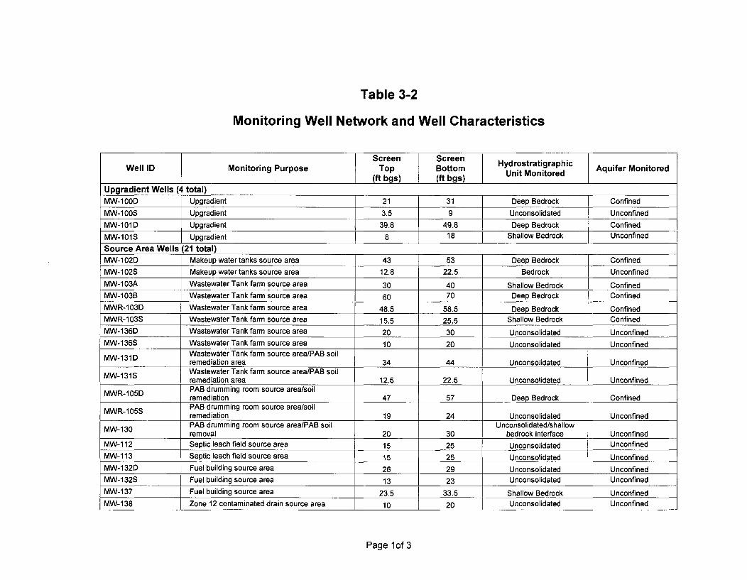
Table 3-2
Monitoring Well Network and Well Characteristics
Screen ScreenWell ID Monitoring Purpose Top Bottom Hydrostratigraphic Aquifer Monitored
(ft bgs) (ft bgs) Unit MonitoredUpgradient Wells (4 total)
MW-100D Upgradient 21 31 Deep Bedrock ConfinedMW-1i00S Upgradient 3.5 9 Unconsolidated UnconfinedMW-101D Upgradient 39.8 49.8 Deep Bedrock ConfinedMW-101S Upgradient 8 18 Shallow Bedrock Unconfined
Source Area Wells (21 total)MW-102D Makeup water tanks source area 43 53 Deep Bedrock ConfinedMW-102S Makeup water tanks source area 12.8 22.5 Bedrock UnconfinedMW-103A Wastewater Tank farm source area 30 40 Shallow Bedrock ConfinedMW-103B Wastewater Tank farm source area 60 70 Deep Bedrock ConfinedMWR-103D Wastewater Tank farm source area 48.5 58.5 Deep Bedrock ConfinedMWR-103S Wastewater Tank farm source area 15.5 25.5 Shallow Bedrock ConfinedMW-136D Wastewater Tank farm source area 20 30 Unconsolidated UnconfinedMW-136S Wastewater Tank farm source area 10 20 Unconsolidated Unconfined
Wastewater Tank farm source area/PAB soilremediation area 34 44 Unconsolidated Unconfined
MW-131S Wastewater Tank farm source area/PAB soilremediation area 12.5 22.5 Unconsolidated Unconfined
MWR-105D PAB drumming room source area/soilremediation 47 57 Deep Bedrock Confined
PAB drumming room source area/soilMWR-105S remediation 19 24 Unconsolidated Unconfined
PAB drumming room source area/PAB soil Unconsolidated/shallowremoval 20 30 bedrock interface Unconfined
MW-112 Septic leach field source area 15 25 Unconsolidated UnconfinedMW-113 Septic leach field source area 15 25 Unconsolidated UnconfinedMW-132D Fuel building source area 26 29 Unconsolidated UnconfinedMW-132S Fuel building source area 13 23 Unconsolidated UnconfinedMW-137 Fuel building source area 23.5 33.5 Shallow Bedrock UnconfinedMW-138 Zone 12 contaminated drain source area 10 20 Unconsolidated Unconfined
Page 1of 3

Table 3-2
Monitoring Well Network and Well Characteristics
Screen Screen HydrostratigraphicWell ID Monitoring Purpose Top Bottom Unit Monitored Aquifer Monitored
(ft bgs) (ft bgs)Downgradient Plume Wells (26 total)MWR-106D Downgradient plume 45 55 Deep Bedrock Confined
MW-1 06S Downgradient plume 14.5 24.5 Shallow Bedrock UnconfinedMW-107D Downgradient plume 90 100 Shallow Bedrock Confined
MW-107S Downgradient plume 15 25 Unconsolidated Unconfined
MW-108 Downgradient plume prior to discharge atdischarge canal 15 25 Unconsolidated Unconfined
MW-109D Downgradient plume prior to discharge atConnecticut River 45 55 Bedrock Confined
MW-109S Downgradient plume prior to discharge atConnecticut River 15 25 Unconsolidated Unconfined
MW-110D Downgradient plume prior to discharge atConnecticut River 70 80 Bedrock Confined
MW-110S Downgradient plume prior to discharge atConnecticut River 15 25 Unconsolidated Unconfined
MW-117 Isolated historic detection on peninsula 15 25 Unconsolidated Unconfined
Downgradient plume near discharge to Multi-level well sampleMW-1 18A Connecticut River - lower bound of plume in zones at: 30, 75, 125,
bedrock 160 & 235 Bedrock Confined
Downgradient plume near discharge to Multi-level well sampleMW-119 Connecticut River- lower bound of plume in zones at: 50, 85, 160,
bedrock 260, 300 & 455 Bedrock Confined
Downgradient plume near discharge to Multi-level well sampleMW-120 Connecticut River - lower bound of plume in zones at: 90, 105, 155,
bedrock 210 & 240_________________Bedrock Confined
Downgradient plume near discharge to Multi-level well sampleMW-121A Connecticut River- lower bound of plume in zones at: 105, 175,
bedrock 285, 315 & 465 Bedrock Confined
MWR-122D Downgradient plume 185 195 Deep Bedrock ConfinedMW-122S Downgradient plume 9 19 Unconsolidated UnconfinedMW-123 Downgradient plume 23.5 33.47 Shallow Bedrock Confined
MW-124 Downgradient plume 11 21 Unconsolidated Unconfined
MW-125 Downgradient plume along preferential flowpathway/Discharge tunnel soil remediation area 11 22 Unconsolidated Unconfined
MW-130 PAB drumming room source area/PAB soil Unconsolidated/shallow Unconfinedremoval area 20 30 bedrock interface
Page 2 of 3

Table 3-2
Monitoring Well Network and Well Characteristics
Screen ScreenWell ID Monitoring Purpose Top Bottom Hydrostratigraphic Aquifer Monitored
(ft bgs) (ft bgs)MVV-133 Downgradient plume along preferential flow
pathway 32 42 Deep Bedrock ConfinedMW-134 Downgradient plume along preferential flow
pathway/Discharge tunnel soil remediation area 18.72 28.72 Unconsolidated UnconfinedMW-135 Downgradient plume 27.72 28.72 Unconsolidated UnconfinedMW-508D Downgradient plume, defines plant north extent
of plume 81.5 91.5 Shallow Bedrock ConfinedMW-508S Isolated perched plume under parking lot 14 24 Unconsolidated PerchedMW-AT1 Downgradient plume 16 41 Unconsolidated Unconfined
Notes:
ft bgs = feet below ground surface
Page 3 of 3

Table 3-3
Target Radionuclides and Detection Limits
I mrem/yr EPA Drinking Required
Radionuclide Groundwater Waterinki Detection AnalysisTarget() Water MCL Limit Category(pCilL) (pCilL) (pCilL)
H-3 26080 20000 400 LSC•)C-14 360 2000 200 LSC
Mn-54 968 300 50 y-isotopicFe-55 2616 2000 25 LSCCo-60 46 100 25 y-isotopicNi-63 1260 50 15 LSCSr-90 10 8 2 GPC(41, LSCNb-94 270 109 50 Y-isotopicTc-99 1056 900 15 LSC
Ag-1 08m 170 44 20 ,-isotopicCs-134 14 80 14 )Y-isotopicCs-1 37 17 200 15 y-isotopicEu-152 293 200 50 Y-isotopicEu-1 54 202 60 50 Y-isotopicEu-1 55 1300 600 50 y-isotopicPu-238 0.60 15 0.50 a-isotopicPu-239 0.54 15 0.50 a-isotopicPu-241 28.40 300 15 LSCAm-241 0.53 15 0.50 a-isotopicCm-243 0.78 15 0.50 a-isotopic
Notes:
1. Generic target dose limit of 1 mrem per year to satisfy sensitivity requirements of theLicense Termination Plan (LTP).
2. Beta/gamma emitters based on 4 mrem per year organ dose equivalent limit. Valuesfor Nb-94 and Ag-108m calculated in accordance with ICRP-2 (Report of ICRPCommittee II on Permissible Dose for Internal Radiation, 1959).
3. Liquid scintillation counting.
4. Gas proportional counting.

Table 3-4
The Criteria and Performance Defined to meet LTP RequirementsAcceptance at the end of the 18-month Clock for License Termination
Criterion Path Forward NRC Acceptance
Conduct quarterly Remediation conducted using Approval from the NRC thatsampling for a groundwater depression was December 2005 is acceptedminimum of 18 months. complete at the end of November as the 18-month monitoring
2005. CYAPCO elected to start plan start date, and thethe 18 month groundwater monitoring plan is approved.monitoring plan in December Complete all sampling,2005, and implemented the analyses and reporting assampling plan. Quarterly samples detailed in the plan.will be collected through June2007.
Collect two seasonal Include the Hard-to-Detect plant The HTDs were collected fromspring high water related suite in the first spring high all wells in April 2006, andsamples. water level samples. If detected, March 2007 will be the second
add those analytes to the list for spring of monitoring.monitoring.
Demonstrate that Calculate the contribution from Ensure the total maximumgroundwater groundwater to the total dose rate dose rate for the HNP site iscontaminant conditions for the site based on analyses of less than 25 mrem/yr from allare below the the quarterly monitoring well exposure pathways after theestablished LTP criteria samples. final analytical results areof 25 mrem/yr for all tabulated.exposure pathways.
Demonstrate that Quarterly monitoring well sampling Verify contaminant levels aregroundwater and analytical results will be below DCGLs.contaminant conditions plotted and compared to theconform to the Derived DCGL's throughout the 18-monthConcentration monitoring period.Guideline Levels(DCGL's).Demonstrate that Provide charts and/or statistical Verify that any detectedgroundwater analyses to indicate steady state contaminants of concern arecontaminant conditions or decreasing contaminant below the DCGL's and theexhibit either stable or concentration activities for trend analyses show steadydecreasing trends. groundwater wells across the site. state or decreasing
concentrations at the end ofthe 18-month monitoringperiod (LTP requirements
___satisfied).

Table 4-1
18-Month License Termination Groundwater MonitoringSchedule
Month SampleSequence Season Month Event Deliverables
0 Dec-05 Winter 051 Winter . t Jan-06
2 Feb-06 Quarterly Summary (Winter 05)3 Mar-06 ..Spring 06
Alphaspectroscopic Semi-Annual GW Monitoring Report
Spring Apr-06 and HTDSamples
5 May-06 Quarterly Summary (Spring 06)
6 Jun-06 Summer06
7 Summer Jul-068_______ Aug-06 Quarterly Summary (Summer 06)
9 Sep-06 Fall 0610 Fall Oct-06 Semi-Annual GW Monitoring Report
11 Nov-06 Quarterly Summary (Fall 06)
12 Dec-06 Winter 06
13 Winter. Jan-07
14 Feb-07 Quarterly Summary (Winter 06)
15 Mar-07 Spring. 07
16 Spring Apr-07 Semi-Annual GW Monitoring Report
17 May-07 Initial Groundwater Compliance SummaryQuarterly Summary (Spring 07)
18 Jun-07 Summer 0719 Summer Jul-07 Final Groundwater Compliance Summary
20 __ Aug-07

CY-07-004
Attachment 2
Radiological Groundwater Monitoring Procedure Set(November 2006)
GPP-GGGR-R0053-000, Rev. CY-002 MajorGGGR-R5300-003, Rev. CY-003 Major
GPP-GGGR-R5302-000, rev. CY-001 MajorGGGR-R5303-000 Rev., CY-002 Major
ISC-GQP-00002-000, Rev. CY-002

NOV 3 0 2006OCT 26 2005GGGP-00001-007Rev. CY-009
Administration
CONNECTICUT YANKEE ATOMIC POWER COMPANYHEALTH PHYSICS
Radiological Ground Water Monitoring
Program (RPM 5.3-0)
GPP-GGGR-R0053-000
Rev. CY-002 Major
VERIFY MOST RECENT REVISIONAGAINST MDI:
INITIALS DJATE
Review:
Approval:
Independent Safety ReviewerDate: /f'-(5
Date:" Si' " "Designated Decommissioning Manager
Effective Date: 0 4,
Level of Use
Information
GGGP-00001-007, Rev. CY-009
Responsible Individual:Brian Couture
Attachment B

NOi NU20UVHealth Physics Procedure GGGR-R0053-000
Rev. CY-002 MAJOR
Radiological Groundwater Monitoring Program Description (RPM 5.3-0)
1.0 PURPOSE AND SCOPE
This document has been prepared to describe the radiological groundwater monitoringprogram implemented to support license termination and facility closure decisions for the
Connecticut Yankee Atomic Power Company's Haddam Neck Plant (HNP) nuclear powerstation. The purpose and scope of the groundwater monitoring plan are described as follows:
1 1 Purpose -The overall objective of the groundwater monitoring program is to provide asound technical basis to support license termination and site closure decisions requiredby the applicable regulations. Specific program objectives are:
1.1.1 Provide groundwater monitoring wells that are located, constructed, andmaintained in a manner that supports their use in collection of representativesamples for site groundwater characterization and compliance monitoring.
1.1.2 Ensure that groundwater samples are collected and analyzed in a manner thatallows for assessment and determination of data quality and ensures efficientdata collection and data management.
1.1.3 Provide groundwater sampling and anal ses that support the regulatory scoperequirements through measurement of the appropriate parameters identified byeach regulatory agency.
1.1 4/ Provide comprehensive assessment and reduction of groundwater monitoringdata such that the results are presented in a clear, understandable manner foruse in license termination and site closure decisions.
1.2. Scope - The HNP groundwater monitoring program is intended to integrate all aspectsof radiological groundwater characterization, monitoring, and remediation that arerequired to support HNP license termination. The program scope includesgroundwater-related requirements defined by multiple regulatory standards andprovides: specification, maintenance, and operation of specific infrastructure and,monitoring systems. ,
2.0 LICENSE AND: ADMINISTRATIVE REQUIREMENTS
The regulatory scope of the radiological groundwater monitoring program supports datacollection and decision management for the HNP License Termination Plan (LTP) and itsassociated Final Status Survey (FSS) requirements established under Nuclear RegulatoryCommission regulations and license provision (see References 5.1 and 5.2). The LTP(Reference 5.3) is regulated by the United States Nuclear Regulatory Commission (USNRC).
2.1 The LTP specifies a minimum 18 month period of groundwater monitoring (to includetwo spring / high water seasons)' to verify the efficacy of remedial actions conductedwith the use of groundwater depression systems. The groundwater monitoringprogram is required to demonstrate that groundwater contaminant conditions are
Page 1 of 1.5.

t-Jov 30 )006Health Physics Procedure GGGR-R0053-000
Rev. CY-002 MAJOR
below the established LTP closure criteria and exhibit either stable or decreasingtrends. These requirements are outlined in the "Groundwater Monitoring Plan toSupport HNP License Termination" (LTP GWMP, Reference 5.4).
3.0 SUPPORT INFORMATION
3.1 Infrastructure and Activity Scope
The groundwater monitoring program is responsible for the following systemelements:
3.1.1 HNP groundwater monitoring well network
The well network consists of a series of wells located to support the LTPGWMP. A list of the wells is provided in Table 3-1 of the LTP GWMP.
3.1.2 Groundwater level monitoring system
This system consists of a series of data-logging pressure transducers placed inselected monitoring wells and at a selected surface water monitoring location.:This system records changes in groundwater and surface water pressure that isconverted to elevation to support interpretation fgroundwaterflfw directionn
and velocity. The wells and surface water monitoring locations included. in.this system are outlined in the LTP GWMP.
3.1.3 Design, specification, and construction oversight of new or modified :monitoring well installations.
3.1.4 Planing and implementin required groUndwater'monit6ring and samplingevents, including the preparation Of subsequent reports.
3.1.5 Maintenance, calibration, and operation of instrumentation required forgroundwater monitoring and characterization. A list of instrumentationutilized by program staff is shown in Attachment 1, which will be. updated asappropriate.
3.2 Organization, Staff and Training
The groundwater monitoring program is identified as a fun6tional requirement of theHNP Site Closure (SC) organization. A typical HNP Site Closure organization isshown in Attachment 2, The current groundwater organization personnel training
..matrix and required reading matrix are shown in Attachmrents.3 and 4, respectively. Alist of current. subcontractors providing services to the groundwater monitoringprogram is included in Attachment 5.
The primary organizational functions related to the groundwater monitoring programare described below.
3.2.1 The Groundwater Project Lead is responsible for the following activities:
Page 2 of 15

Health Physics ProcedureiV 2D 3 0 600
GGGR-R0053-000Rev. CY-002 MAJOR
3.2.2
a. Developing and implementing this program and associated procedures;
b. Establishing, staffing and managing the Groundwater organization;
c. Monitoring closure cost and schedule performance;
d. Advising the Decommissioning Director on groundwater monitoringissues; and
e. Performing as the closure project lead and providing regulatory interfacewith respect to license termination and groundwater monitoring issues.
The Groundwater Technical Lead is responsible for the following activities:
a. Recommending activities and tecl-miques appropriate for investigating thenature, extent, fate and transport of contarninants in groundwater;
b. Developing sampling procedures;
c. Overseeing the assessment and analvsis of giround water monitoring .data;
d. Performing assessments of data for use in Ground Water MonitoringReports; and
e. Preparing Ground Water Monitoring Reports.
The Site Closure Technical Support Manager is responsible for:
a. Providing technical guidance and advice on radiological issues pertainingto radionuclide mix, survey protocols and detection levels;
b. Providing technical guidance on ground water monitoring instrumentselection and laboratory analysis specifications;
c. Advising on database development and operation;
d. Supporting procedure development;
e. Assisting in survey and sanipling training; and
f. Evaluating laboratory results.
The Field Sampling Coordinator is responsible for:
a. Preparing plans and associated documentation to support groundwatersampling events;
b. Providing daily supervision and guidance to field sampling crews;
3.2.3
3.2.4
Page 3 of 15

N 3 0 2006Health Physics Procedure GGGR-R0053-000
Rev. CY-002 MAJOR
c. Performing quality checks of field activities;
d. Coordinating availability of field instrumentation and equipment; and
e. Overseeing the sample preparations for transferring or shipping thosesamples to either onsite or offsite laboratories.
3.3 Requirements for Supporting Documents and Procedures
The following plans, documents; and procedures have been identified as requirementsfor implementation of the groundwater monitoring prograrn:
3.3.1 Groundwater Monitoring Program Quality Assurance Plan (Reference 5.5)
3.3.2 Groundwater Level Measurements and Sample Collection in Monitoring Wells(Reference 5.6)
3.3.3 Monitoring Well Drilling and Completion (Reference 5.7)
3.3.4 Groundwater Sample Event Planningiand Data Management (Reference 5.8)
3.3.5 Groundwater Monitoring Plan to support HNP License Termination(Reference 5.4)
4.0 INSTRUCTIONS
4.1 Safety-
The HNP groundwater program management is committed to performing allgroundwater-related activities ina safe manner consistent with HNP procedures and
requirements and industry-standard safe work practices.The following subsections present a prelininaryoverview of1hazards presented by the
planned groundwater program activities and hazard mitigation requirements. Thisdiscussion is not intended to be encyclopedic and hazard assessments will be reviewedfor each successive field activity.
4.1.1 Hazard Overview
The. hazards presented to' project personnel perfoming goundwatermonitoring activities fall into the following general categories:
a. Mechanical Hazards (e.g., electrical hazards, underground utilities. pinchpoints, stacked materials, moving•loads, suspended loads, rotating parts,high-pressure hydraulic/pneumatic systems)
b. Environmental Hazards (e.g., heat and cold stress, poisonous snakes,insects [e.g., bees, ticks], icy and otherise slippery surfaces, noise,reduced visibility due to dust or fog, severe weather [e.g., blizzard.lightning, tornado], insufficient lighting)
Page 4 of 15

FU\1 0 LI6U-Health Physics Procedure GGGR-R0053-000
Rev. CY-002 MAJOR
c. Location Hazards (e.g., roadway traffic, soft and unevenwalking/working surfaces, water hazards when working near open water,flooding [e.g., diurnal due to tidal fluctuation, or river flooding],unrelated hazards posed by work performed by others at adjacentlocations, open excavations)
d. Chemical and Radiological Hazards (e.g., chemical preservatives forsamples, exposure to radioactive and non-radioactive site contaminants insoil and groundwater, radiological dose from source materials at, or near,work locations)
e. Activity-Related Hazards (e.g., vehicle operation hazards, lifting heavyobj ects/containers)
Each activity will be evaluated during the planning phase and planning willinclude a site walk-down in all cases, to identify potential hazards associatedwith the activity.
4.1.2 Hazard Mitigation Requirements
identified hazards associated with the groundwater monitoring programactivities will be mitigated using the following general approaches, in order of
preference:
a. Work Planning - Work activities will be plamned to avoid hazardouslocations when possible and identify less-hazardous Work processes.This includes stfingent 1pplication of the ALARA principles to minimize
personnel exposure to hazardous conditions. TaSk-specific training maybe provided to personnel duringthe planning effortto ensure safe
operations. Hazard mitigation through planning may include relocatingwork sites to avoid traffic interference, moving wrk at
from open water, or scheduling work to be performed during daylighthours when adequate natural light is available. When working in trafficareas, traffic spotters will be assigned..
b. Engieered Controls -Enineered controls will be used to minimizepersonnel exposure to hazards and to~reduce specific hazards (e.g.,mechanical hazards). Examples of applicable engineered controlsinclude temporary shielding to reduce radiological dose, shoring orsloping to create stable excavation sidewalls, proper electrical groundingand use of electrical protective devices (e.g., GFCI), whip-checks onpressurized lines, pressure-relief devices on pressurized systems,enhanced ventilation, or containment in negative-pressure structures.Controlled-entry zones will be established around work areas usingCaution tape and stanchions to prevent other personnel frominadvertently entering the work area.
Page 5 of 15

Nv30 2ZOEHealth Physics Procedure GGGR-R0053-000
Rev. CY-002 MAJOR
c. Personal Protective Equipment - Personal Protective Equipment (PPE)will be used as needed to protect individual personnel from exposure toidentified hazards. Basic personal protective equipment will be used atall times during groundwater program field activities and includeswearing an approved hardhat and safety glasses, durable footwear,durable work clothing, and appropriate hand protection (e.g., leatherwork gloves when handling materials or working with hand tools,appropriate chemical resistant gloves when handling contaminated soil orgroundwater). Additional equipment may be required for work inspecific locations or during specific tasks (e.g., air rotary drilling whereadditional splash protection may be required). Personnel will wear high-visibility clothing when working in traffic areas.
4.1.3 Hazard mitigation will be implemented for each task based on the uniquehazards identified for the task, following the priority of planning, engineeredcontrols, and personal protective equipment. For repetitive tasks, a periodicreview of hazards and mitigation practices will be performed.
4.1.4 Reporting and Treatment of hijuries - All injuries to personnel, no matter how.minor, will be treated by plant first aid personnel and immediately reported toupper management.
4.2 Groundwater Sampling Events
Groundwater sampling events will be performed as required. The cycle of eventplanning,j implementation, and reporting will be repeated for each sampling event.
4.2.1 Planning - Groundwater sampling event planning will be performed inaccordance with HNP procedure Groundwater Sample Event Planning andData Management (Reference 5.8). Groundwater monitoring sampling eventsmay include numerous measurements that are repeated each event, but specificsingle-event measurements may be required by specific programs. Eachplarning event will include a review of the past event(s) to identify anynecessary corrective actions based on the previous results. Event-specific dataquality objectives will be defined during the planning activity.
4.2.2 Implementation - Groundwater sampling will be conducted in accordance withHNP procedure Groundwater Level Measurements and Sample Collection inMonitoring Wells (Reference 5.6).
Each groundwater sampling event requires a number of logistical andintegration activities that include the following:
a. Scheduling laboratory services;
b. Procuring a sampling subcontractor (if needed);
Page 6 of 15

NOV f30 200Health Physics Procedure GGGR-R0053-000
Rev. CY-002 MAJOR
c. Procuring appropriate sample containers and sample preservatives. Theuse of pre-preserved sample containers is recommended to minimizehazards associated with handling bulk preservatives in the field;
d. Coordinating with HNP craft support (e.g., laborers, teamsters andoperating engineers) as needed to ensure timely work progress;
e. Testing and calibrating field instruments;
f. Conducting pre-job briefings of persormel to ensure understanding oftask requirements;
g. Collecting the samples and field measurements;
h. Shipping samples to the appropriate laboratory for analysis; and
1. Review of field records for completeness, and filing of field records.
4.2.3 Reporting - Reporting groundwater monitoring event results will be performedassrequired and will be submitted to the applicable regulatory agency. At aminimum groundwater monitoring reports will be prepared in accordance withHNP GWMP (Reference 5.4).
The general activities to prepare a groundwater monitoring report include thefollowing:
a.. Data Quality Assessment- DQA will be performied for each event. TheDQA will include evaluation of field parameters and off-site laboratoryquality assurance results to identify and quantify data quality against.established data qualityobjectives. and metrics. Specific attention will begiven to evaluation of actual. versus reported detection limits forradiochemical analyses. All mreasurements, including field analyses, willbe subjected to the DQA process as defined in the GroundwaterMonitoring Program Quality Assurance Plan (Reference 5.5).Appropriate data qualifiers will be assigned to measurement results basedon the DQA.
b. Data Reduction - The qualified data generated from the DQA will bereduced to enhance data usability. Data reduction activities may includetabulation of results, segregation of detections from non-detect results,assessment of concentration changes over time,.preparation of spatialdistribution maps and concentration iso-contour maps as appropriate, andcomparison of measurement results to established groundwater qualitymetrics and standards.
c. Assessment of Conclusions and Recommendations - If the event data setprovides a basis for conclusions, these will be presented in the report. In.addition, any recommendations for future sampling events will be
Page 7 of 15

NO• 0 v iHealth Physics Procedure GGGR-R0053-000
Rev. CY-002 MAJOR
identified (e.g., indications for additional monitoring locations,
recommendations for added, or reduced measurements at specificlocations).
d. The groundwater monitoring report will be subjected to internal HNPreview, for technical content prior to publication for distribution outsidethe project. The published report will include all measurement results inaddition to the qualified and reduced data.
4.2.4 Automated Water Level Monitoring
a. The automated water level monitoring system consists of a series of self-contained in-well pressure transducers with integral data loggingcapability. The devices used at HNP are Mini-TrollTm transducer/dataloggers manufactured by In-Situ, Inc., of Laramie, Wyoming. Thesedevices are installed and operated according to the manufacturer'soperating instructions.
b. The transducer network integral data logs will generally be downloadedon a monthly basis, or more frequently if indicated by site conditions, orcharacterization needs. The electronic data set will be maintained in itsoriginal downloaded format, with copies of the data used fortransformation, barometric pressure correction, and further reduction.Transducer readings will be periodically verified by comparison to handmeasurements of depth to groundwater at the specific -wells. where thesystem is installed.
c. The results of the water level monitoring activity will be included-in.thegroundwater monitoring event reports. Supplemenital, event-specificresults may be presented in supplemental technical support documents. Ortechnical memoranda.
4.2.5 Well Inspection and Maintenance
The groundwatermonitoring wells are part of the engineered system providingthe overall groundwatermonitoring capability at HNTP. As engineereddevices,the wells require periodic inspection, maintenance, and repair. The inspection"requirements for monitoring wells are identified in HN? procedure MonitoringWell Drilling and Completion (Reference 5.7).
In general, all wells will be inspected in conjunction with the groundwatersampling event. At that time, maintenance requirements Wvill be identified andminor repairs will .be made immediately (e.g., replacement of missing ordamaged seals or cover bolts). More involved repairs will be scheduled andimplemented as deficiencies are identified following the inspection. Wellslocated in high traffic areas of the facility may be inspected on a monthly basis.
4.2.6 Well Design, Specificationand Construction Oversight
Page 8 of 15
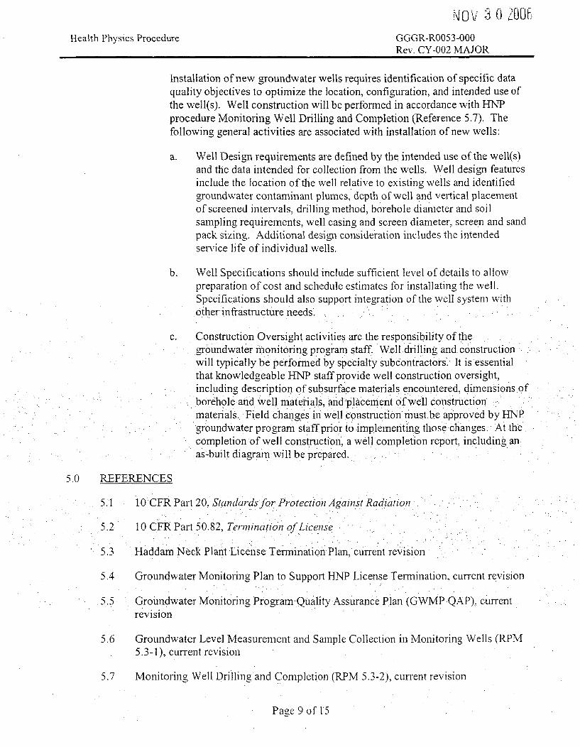
NUiULHealth Physics Procedure GGGR-R0053-000
Rev. CY-002 MAJOR
Installation of new groundwater wells requires identification of specific dataquality objectives to optimize the location, configuration, and intended use ofthe well(s). Well construction will be performed in accordance with HINPprocedure Monitoring Well Drilling and Completion (Reference 5.7). Thefollowing general activities are associated with installation of new wells:
a. Well Design requirements are defined by the intended use of the well(s)and the data intended for collection from the wells. Well design featuresinclude the location of the well relative to existing wells and identifiedgroundwater contaminant plumes, depth of well and vertical placementof screened intervals, drilling method, borehole diameter and soilsampling requirements, well casing and screen diameter, screen and sandpack sizing. Additional design consideration includes the intendedservice life of individual wells.
b. Well Specifications should include sufficient level of details to allowpreparation of cost and schedule estimates for installating the well.Specifications should also support integration of the well system withother infrastructure needs.
c. Construction Oversight activities are the responsibility of thegroundwater monitoring program staff. Well dril.ling and constructionwill typically be performed by specialty subcontractors. It is essentialthat knowledgeable HNP staff provide well construction oversight,including description of subsurfacie materials encountered, dimensions ofborehole and well materials, and placement of well construction.materials. Field changes in well construction must.be approved by HNPgroundwater program staff prir to implementing those changes. At the
completion of well construction, a well completion report, including anas-built diagramrwill be prepared.
5.0 REFERENCES
5.1 10 CFR Part 20, Standardsfor Protection Against Radiation'
•5.2 10 CFR Part 50.82, TerminatiOn of License
5.3 Haddam Neck Plant License Termination Plan, current revision.
5.4 Groundwater Monitoring Plan to Support HNP License Termination, current revision
5.5 Groundwater Monitoring Program Quality Assurance Plan (GWMP QAP), currentrevision
5.6 Groundwater Level Measurement and Sample Collection in Monitoring Wells (RPM5.3-1), current revision
5.7 Monitoring Well. Drilling and Completion (RPM 5.3-2), current revision
Page 9 of 15

N ('. 0 0U6Health Physics Procedure GGGR-R0053-000
Rev. CY-002 MAJOR
5.8 Groundwater Sample Event Planning and Data Management (RPM 5.3-3), currentrevision
6.0 ATTACHMENTS
6.1 Attachment 1 - Radiological Groundwater Monitoring Program Instrumentation
6.2 Attaclmnent 2 - HNP Site Closure Organization Chart
6.3 Attachment 3 - Radiological Groundwater Monitoring Program Training Matrix
6.4 Attachment 4 - Radiological Groundwater Monitoring Program Required ReadingMatrix
6.5 Attachment 5 - Radiological Groundwater Monitoring Program Subcontractors(Typical)
7.0 SUMMARY OF CHANGES
Revisions made to this procedure reflect the long-term groundwater monitoring requirementsof the NRC and CTDEP, and change in project organization.
Page 10 of 15

Health Physics Procedure NOV S U 2006GGGR-R0053-000Rev. CY-002 MAJOR
Attachment I
Groundwater Monitoring Program Instrumentation
Instrument
Electronic Well Sounder (e-tape)
Multi-parameter Water Quality Analyzer(pH, ORP, ECE, Temirp, DO)
Data Logging Pressure Transducers(Mini-TrollTM)
Data•Logging Barometric Pressure
Transducers (Bar••Trol6l T
Turbidity Meter (2020 TurbidimeterTM)
Manufacturer
Solinst
YSI
In-Situ
In-Situ
LaMotte
Number Avahilable
2
36
2,
Multi-port Sampling SYstem Westbay 2
Page I I.of 15

Wv` J 0 ( 2000iHealth Physics Procedure GGGR-R0053-000
Rev. CY-002 MAJOR
Attachment 2
HNP Integrated Site Closure Typical Organization Chart
Site ClosureProject Manager
AdministrativeAssistant
ISC Technical RCRA / Final StatusSupport Manager Groundwater Survey Project
Proiect Lead Lead
Technical Suport Technical FSS TechniciansEnaineers Subcontractors
Page 12 of 15

No v 31 GGGGR-R0053-000Rev. CY-002 MAJOR
Health Physics Procedure
Attachment 3
Radiological Groundwater Monitoring Program Training Matrix
Description:
HazWoper Technician(OSHA 40-hr and refresher)
Electronic Well SounderOperation
Multi-parameter Water QualityAnalyzer
Data LoggingPressureTransducers
Turbidity Meter
Multi-port Samllling System
Reference
IS-00017-l
FieldScientist-Engineer
R
R
R
R
.R
R
Technical ProjectLead Lead
N
P
P
P
p
R
P
P
P
P
P
Notes:R.=1• N :
RequiredNot RequiredPrior to Perfornmng Ta.skManufacturer's operating instructions.
Page 13 of 15

GGGR-R0053-000Rev. CY-002 MAJOR
Health Physics Procedure
Attachment 4
Radiological Groundwater Monitoring Program Required Reading Matrix
Description
Excavation Backfill and Storm Water ErosionControl
Grouind Water Monitoring ProgramQuality Assurance Plan
Radiological Ground Water MonitoringProgram
Ground Water Level Measurement & Sample.Collection in Monitoring Wells
Monitoring Well Drilling and Completion
Gro G rIund Water Sam"ling Event Plann g,and Data Ma..agement
Reference
GPP-GGGC-00023
ýISC-GQP-00001
RPM 5.3-0
RPM 5.3-1
RPM-5 3-2
RPM 5.3-3
-FieldScientistEngineer
R
R
R
RR
Technical ProjectLead Lead
P
R
R
R
R
R
R
R
R
R
R
R
Notes:R RequiredN =. Not RequiredP = Prior to Performing Task
Page 14of15

NOV 3 0 2006Health Physics Procedure GGGR-R0053-000
Rev. CY-002 MAJOR
Attachment 5
Radiological Groundwater Monitoring Program Subcontractors (Typical)
Subcontractor .S.cope of Work
Aquifer Drilling & Testing, Well drilling and construction, soil boring and subsurfaceInc. (ADT) sampling, direct push sampling.
MACTEC Engineering and Technical support services and groundwater sampleConsulting (MACTEC) collection, packaging, shipment
Severn Trent Laboratories Analytical Laboratory Services(STL)
G SI.IerL g Analytical Laboratory ServicesLabortatories (GEL)
CH2M HILL Hydrogeological technical support services.Ra~diation Safety'.&,.Co~it/ri : . .. . - " .. .. .::;. .. .i ".•". - ... . •"Radiat~in t~ &oS ntro Geology and radiochemistry techcal support
Ser-ices, iRS S)
Page 15 of 15

OCT 26 2005Administration GGGP-0000 1-007
Rev. CY-009
CONNECTICUT YANKEE ATOMIC POWER COMPANYHEALTH PHYSICS
Groundwater Level Measurement and Sample
Collection in Monitoring Wells (RPM 503-1)
GGGR-R5300-003
Rev. CY-003 Major
VERIFY MOST RECENT REVISIONAGAINST. MDI:.,
JNTIALS DATE
.k/ / A-Review:_
Approval:
Independent Safkety ReviewerDate:
7 7Designated Decorhiinssioning Manager
Effective Date: / / - 3c( *--OC (1
Level of Use
General
GGGP-00001-007, Rev. CY-009
Responsible Individual:Brian Couture
Attachment B

Health Physics Procedure GGGR-R5300-003Rev. CY-003 Major
GROUNDWATER LEVEL MEASUREMENT AND SAMPLE COLLECTION INMONITORING WELLS (RPM 5.3-1)
1.0 OBJECTIVE
To describe the methods for measurement of ground water levels and collection of.representative samples of ground water from conventional and multiport (Westbaye)monitoring wells. The list of wells to be samples will be provided in the appropriategroundwater monitoring work plan.
2.0 REQUISITES
2J1 Representative samples of ground water must be collected frommonitoring wells and analyzed in order to demonstrate compliance withthe Groundwater Monitoring Plan to support Haddam Neck Plant licensetermination or the Resource Conservation and Recovery Act (RCRA).
12 Groddatersanpling.wiII commence a minimum of fi1e days followiif
.monitoring well development activities.
3.0 INSTRUCTIONS
3.1 Equipment.and Materials Staging
3.1.1 REVIEW the individual well sampling plan.
3.1.2 IF performing synoptic, or individual, water level monitoring,THEN OBTAIN the equipment in Attachmnent A, as necessary.
3.1.3 IF performing water sampling, THEN OBTAIN the equipment inAttachment B for conventional wells and in Attachment C forWestbay® wells, as necessary.
3.1.4 DO NOT USE a peristaltic pump when collecting samples forVOCs analysis. Peristaltic pumps also have limited lift capacityand are ineffective where the depth to water exceeds 20 feet
3.2 Well Inspections
3.2.1 OBSERVE the area surrounding the well and the well itself andNOTE the existence of any unusual conditions, e.g., groundstaining from possible oil or gasoline spills or damage to the well.
• Inspect the well head and confirm that the well casing compressioncap is in place. If necessary, confirm that the cap is tight and thatthe tamper-indicating seal is present. Record the inspectionobservations on Attachment D. If unusual conditions exist,
a. DO NOT proceed with that well.
Page 1 of 44

N"OV ; 0~ 1rHealth Physics Procedure GGGR-R5300-003
Rev. CY-003 Major
b. DESCRIBE the condition(s) in the comments section ofAttachment D, or equivalent, and in the field log book.
c. NOTIFY ground water project supervision.
3.2.2- CONTINUE if no unusual conditions exist..
3.3 Ground Water Level Measurement
33..1 Connecticut River Level Determination
a. A subset of wells in the monitoring network are subject tothe tidal influences .of the Connecticut River. Forthese.wells, OBTAIN the surface water level-of the Connecticut:River by the designatedelevation benchmark wheneverwater level measurements are taken in association withsynoptic measurements. Secondary data collection (e.g.,•use Of USGS or other nieasuremet sources) m~ybe used
to identify river level elevation.
b. RECORD the synoptic Water level measurements on,Attachment E or equivalent forn and the field log book.
3-3..2 Synoptic Measurements of Depth to Ground Water Surface
a. OPEN the. well cover, RECORD the tamper-indicating sealserial number and REMOVE, if present. LOOSEN thewell cap carefully to relieve any built up pressure that may*be attributed to fluctuation of hydraulic gradients. If arelief of pressure is noted (i.e., by the sound of air leavingor entering the well) wait 15 minutes before taking thewater elevation measurement.
1. If the wellhead is submerged with water, REMOVEstanding water from within the curb box to a levelbelow the top of the well casing before opening thecasing.
2. Put removed water into a container if required.
3. NOTE any unusual odors, sounds or difficultyopening the well.
4. EXERCISE CARE to not introduce any foreignmaterial into the well. If there is any potential forsurface water or foreign materials to enter the well,do not leave the well open and unattended. At thecompletion of the water level measurements, each
Page 2 of 44

N0 V 0 2050Health Physics Procedure GGGR-R5300-003
Rev. CY-003 Major
well cap will be closed until access is required forsample collection.
b. If the well casing does not have a reference point (usually aV-cut or mark on the well casing), make one. DESCRIBE
* its location and RECORD the date of themark in thelogbook.
c. MEASURE the depth to groundwater. Water levelmeasurement must be performed before any purging orsampling activities begin*;
1. TURN the electric water level meter on and test theoperational status by either placing the end of theprobe in clean water or by use of the probe testsystem. The measurement should be taken at thenotch filed oni the top of the P.VC. )pe. The. notchmay o -may.not, also be marlked wilth an indeliblemarker. •
' 'Slowly LOWER the probe into the. well andCONTINUElowering until the tone sound indicatesthat contact with the water has been achieved.
3. REPEAT raising and lowering the probe via thecable using slight movements and keeping yourhead and face away from. the well head, whilelistening to the indicator, until the water levelsurface in the well can be determined tothenearest0.01 feet from the top of the PVC riser.
4. Record the measured depth-to-water on theSynoptic Water Level Measurement Data Sheet(Attachment E), or equivalent form, and in the fieldlog book.
5. As the cable is withdrawn from the well, dry thecable and probe using a clean damp cloth, or papertowel(s).
6. The well shall not be sampled if any liquid, otherthan water, is present on the water level meterprobe. A note of the condition shall be made onAttachment E or in the field log book and the wellshall be closed and locked. The probe shall not beused again until it is decontaminated.
Page 3 of 44

N'OV 3 0i :-O-lr.Health Physics Procedure GGGR-R5300-003
Rev. CY-003 Major
7. PLACE the probe into the probe holder of the meterto prevent it from becoming contaminated. At notime shall the probe and/or cable come in contactwith the ground surface.
d. Replace the. compression cap.. If necessary, tighten cap,CLOSE and LOCK the well (if equipped with a lock).
e. SECURE the area.34. Automated Water Level Monitoring
3.4.1 The automated water level monitoring system consists of a seriesof self-contained in-well pressure transducers with integral datalogging capability. The devices to be used are Mini-T-oflPll1
tran.sducer/data Ioggers mann factured :in-Sit. inc...Wyoming. These devices are installed and operated accordi.-, tothe manufacturer's operating instructions. This system records.changes in pressure which may then be used to calculate changesin groundwater and surface water elevation. This data will then beused to support interpretation of groundwater flow direction andVelocity. The wells and surface water monitorins locations that areincluded in this system are shown in Attachment E or equivalent
.form and in the field log book.
3.4.2 The transducer nietwork will generally be downloaded on aquarterly basis, or more frequently if indicated by site conditions,inor character zation needs. The electronic data set will bemaintained in its ori ginal downloaded format, with copies of thedata used for data manipulation, barometric pressure correction,and further reduction. Transducer readings will be periodicallyverified by comparison to hand measurements of depth togroundwater at the specific wells where the system is installed.
3.4.3 The results of the water level monitoring will be included in thesermi-annual groundwater monitoring report. Supplemental, event-specific, results may be presented in supplemental technicalsupport documents or technical memoranda.
3 A.4 Downloading of transducers will follow the manufacturer'soperating instructions. Interpretation and manipulation of the datawill be determined by the end data use.
3.5 Low Flow Sampling and Purging.
Page 4 of 44

Health Physics Procedure GGGR-R5300-003Rev. CY-003 Major
These procedures outline the USEPA Low Stress (low flow) Purging andSampling Procedure for the Collection of Groundwater Samples fromMonitoring Wells, Region I (SOP #GWOOO I). (USEPA, 1996). Anymodification to the following procedures is acceptable, as long as themodifications are acceptable to the governing USEPA procedure.
3.5.1 PREPARE area and equipment for sampling.
a. The well may be purged using a dedicated bailer, bladder,peristaltic, submersible, or Waterra-style pump.
b. MINIMIZE the potential for cross-contamination.
1. If required, SPREAD a clean, unused polyethylenesheet on the ground.
2 RETAIN the bailer, nylon string, put>. trubing,batterv, electronic water level meter and samplebottles, as appropriate, on the sheet duringsampling.
• : Tominimnize potential cross contamination, tubingand bailers will be dedicated.
4. Disposable equipment will be discarded after eachuse....
5. Pumps, transducers, and water level meters will bedecontaminated. before/after each use.Decontamination will include rinse with LiquinoxTM (or equivalent) and potable water, followed byrinsing with deionized water.
6. Exercise caution to prevent cross-contaminationwhenever the potential for coming into contact withground water exists (i.e., well purgingsamplecollection).
3.5.2 MEASURE the water level according to Section 3.3 and recordthis on the Groundwater Field Parameter Data Sheet, AttachmentG, or equivalent and in the field log book.
3.5.3 INSTALL Pump or Tubing
a. LOWER pump, safety cable, tubing, electrical lines, or airlines SLOWLY (to minimize disturbance) into the well tothe midpoint of the zone to be sampled.
Page 5 of 44

Health Physics Procedure GGGR-R5300-003Rev. CY-003 Major
b. If possible, MAINTAIN the pump or tubing intake at least•two feet above the bottom of the well, to minimizemobilization of particulates present in the bottom of thewell. Collection of turbidity-free water samples may beespecially difficult if there is less than two feet of standingwater in the well. Unless instructed differently, the. pump.,intake should be placed at the middle of the screenedinterval.
3.5.4 Before starting pump, MEASURE the water level to verify thewater displacement has returned to the approximate initial Watertable level.
3.5.5 PURGE Well...
a. START the pump at its lowest speed setting and- SLOWLYincreasC the speed until diCscharge OCCLIuS..Fluids gcncrLtw.:d
••.duing Well purging: xill. be discharged to the groul dsurface at each well location! Fluids must be contained ifthe area is paved, however the purge water may then.be.discharged to the ground surface as long as the water.infiltrates the soils and DOES NOT enter the stormwatersystem.
b. CHECK-the water level.
c. ADJUST the pump speed so that there is little or no waterlevel drawdown (less than. 0.3 feet). If the minimaldrawdown achieved exceeds 0.3 feet, but remains stable,continue purging until indicator field parameters stabilize.
3.5.6 MONITOR and RECORD the water level and pumping rate everythree to five minutes (or as appropriate) during purging and recordon Attachment G, or equivalent, and in the field log book.
a. MEASURE the pumping rate by directing the pumpdischarge into a graduated beaker and TIMING the rate atwhich it fills.
b. ADJUST the pumping rate as needed. Flow rateadjustments are best made in the first fifteen minutes ofpumping to help minimize purging time. During pumpstart-up, drawdown may exceed the 0.3 feet target and then"recover" as pump flow adjustments are made.
C. MAINTAIN a water level above the pump intake level.
Page 6 of 44

Health Physics Procedure GGGR-R5300-003Rev. CY-003 Major
d. IF the static water level is above the well screen,MAINTAIN a water level above the pump intake level.
e. IF the recharge rate of the well is lower than extraction ratecapabilities of currently manufactured pumps, or bailing,and the well is essentially dewatered during purging,REMOVE the pump, if applicable
1. For wells completed as flush mount or with roadboxes, CLOSE and SEAL the well. INSTALL anew tamper-indicating seal and/or pad lock. Forwells completed as stickups, loosely place thecompression cap on the PVC casing to allow thewell to .breathe and .lock the casing with a pad lockand/or a new tamper-indicated seal. Do not leavethe well open and unattended.
2. MONITOR the recharge rate of the monitoring c,\~llperiodically over several hours, or days as needed.
3. SAMPLE the well: as soon as the water level has..
recovered to a sufficient level to collectithe required,sample volume. Stabilization of the indicator fieldparameters is not required, since the recharge wateris considered representative of the aquifer.
3.5.7 MONITOR the i ndicato'r field parameters during well purgingevery three to five minutes (or less frequently, if appropriate).
a. During the early phase of purging, emphasis should be puton minimizing and stabilizing pumping stress, andrecording those adjustments.
b. MONITOR field parameters using a Flow-Through-Cell.Transparent flow-through cells are preferred, because theyallow field personnel to watch for particulate build-upwithin the cell.
1. If a flow-through-cell cannot be used, PARTIALLYFILL a container with purge water andSUBMERGE the field parameter measuring devicesinto the container.
2. Turbidity measurements must be measured using aseparate meter through a by-pass assembly before
the purge water enters the flow-through-cell.
Page 7 of 44

Health Physics Procedure GGGR-R5300-003Rev. CY-003 Major
c. RECORD the field parameters results on Attachment G, orequivalent, and in the field log book. Purging is consideredcomplete and sampling may begin when all the indicatorfield parameters have stabilized.
d. EVALUATE the field parameters for stabilization.Stabilization is considered to be achieved when threeconsecutive readings, taken at three (3) to five (5) minuteintervals, are within the following limits:
1. Turbidity (±-10% for values greater than 1 NTU);
2. Dissolved oxygen -,DO (±10%);
3. Specific conductance (±3%);
4. Teiperaiture (±3%)
. .5. pH (± 0.1 standard.unit); and p
6. Oxidation-Reduction potential/ Eh (± 10 mV)
e. If the field parameters are outside of the above limits,CONTACT the groundwater project lead. Thegroundwater project lead may direct sample collectionupon discussion with the field sampling.team and/or prior.historical knowledge of a specific monitoring well.Groundwater sample collection must be competed inaccordance with, the alternative methods provided in theUSEPA Low Stress/Low Purge Procedure (USEPA, 1996).
3.6 Ground Water Sample Collection - Conventional Wells
3.6.1 MINIMIZE the potential for cross-contamination.
a. Samples must be obtained using a dedicated bailer,dedicated tubing with peristaltic pump, bladder pump, or asubmersible pump. With the. exception of the dedicatedtubing and peristaltic pump, all pumps will bedecontaminated using the applicable steps in Section 3.8 ofthis document.
b. Personnel performing sampling shall WEAR new latex ornitrile gloves WHILE COLLECTING samples and nottouch the inside surfaces of sample containers or caps.
c. IF a sample cap falls on the ground during sampling, USE anew sample container or cap.
Page 8 of 44

Health Physics Procedure GGGR-R5300-003Rev. CY-003 Major
3.6.2 STAGE all sample containers, preservatives and plastic coolers asnecessary.
a. A plastic cooler with ice packs or ice shall be used as thesample carrier for samples that must be stored at 4 to 6degrees Celsius..
b. REFER to the individual groundwater sample plan'for thetype and quantity of sample preservative and for the samplevolume. IF an individual well sample plan is not available,REFER to Attachments I and Jfor additional informationregarding typical sample containers, volumes andpreservatives.
3.6.3 SELECT the sample containers to be filled.
3.6.4 UNCAP and FILL only one containcr at a tMic.
3.6.5 ADD preservative to the sample container, if applicable.
3.6.6 IDENTIFY each'sample container with the sample identificationnumber, date and time of sample collection, analysis requested andpreservatives if any. Fill in.the information on the label orcontainer with a water-proof indelible pen before samplecollection. Use the sample ID as noted in the groundwatersampling plan. Samples collected under the LTP program, willhave the following nomenclature:
MWXXX(S/D)-YYQQ-XXX
Where:MWXXX indicates monitoring well number(S/D or A/B) optional alphanumeric descriptor for paired wellsYYQQ sample date.(year/quarter)XXX sequential number well was sampled during thequarter
Sample nomenclature for the RCRA program is defined in theRCRA Quality Assurance Project Plan (QAPP) (MACTEC, 2006).
3.6.7 COLLECT the ground water sample
a. COLLECT the ground water samples in the followingorder, if necessary,. after pre-sampling stabilization of fieldparameters have been met:
1. Volatile organic compounds (VOCs)
Page 9 of 44

Health Physics Procedure GGGR-R5300-003Rev. CY-003 Major
2. Semivolatile organic compounds (SVOCs)
3. Unfiltered inorganic compounds (metals)
4. Filtered inorganic compound, if required
5. PCBs
6. Pesticides
7.. Herbicides
8. Cyanide
9. Radiological constituents
b. Low Flow Sampling
1. COLLECT the sample from a port/tube upstream ofthie flow-through-cell (use a by-pass assembly or.
• disconnect cell to obtain sample).2.. A by-pass assembly mustbe placed upstream of
effluent tube and flow-through cell to avoid sampleoff gassing due to pressure changes.
3. VOC sample aliquots should be collected beforethose for other analytical parameters and putdirectly into pre-preserved sample containers.. TheVOC vial should be tilted on an angle as it is filled.Fill all sample containers by allowing the pumpdischarge to flow gently down the inside of thecontainer with minimal turbulence.
c. Bailer Sampling
I. Slowly LOWER the bailer into the well and allow itto fill.
2. Slowly WITHDRAW the bailer by the nylon string,coiling the string on the plastic sheet, or drape overhand, so it does not come into contact with theground.
3. WHEN the bailer has been retrieved, EMPTY thebailer such that the contents enter the sample
container.
Page 10 of 44

If-'u I i. __ O ,, i
Health Physics Procedure GGGR-R5300-003Rev. CY-003 Major
4. REPEAT above steps until desired sample volumeis obtained.
5. USE pre-preserved sample bottles, or ADDpreservative, as required by analytical methods, tosamples immediately after they are collected if thesample containers are not pre-preserved.
d. Samples collected for Volatile Organic Compounds (VOC)analyses.
1.. ENSURE the preservative is in the VOC containerprior to sampling.
Slowly FILL the container from a steady flow ofwater from the bailer or pump. Do not aerate theS.L.. C dsanflur .Sidismp.!C collection. Fill botl cuFtilithereis aconvex meniscus at the brim of the bottle:before capping. (Samples collected for volatileorganic compounds must-be devoid of air bubbles.).
3. FILL and CAP the. conainer. Then TURN the:container upside down to ENSURE that no bubblesare present in the sample container.
(a) TAP the container ligAtly on your hand todislodge any bubbles.
(b) IF any bubbles are observed, THEN OPENthe container and slowly add more water.
e. Samples collected for other analyses
1. FILL the preserved containers, leaving a smallamount of air space, directly from the bailer orpump tubing.
2. ADD preservative, if necessary.
3. CAP the container(s).
4. INITIATE a Chain-of-Custody. (COC) form.
(a) ENSURE the COC form remains with thesample.
Page 11 of 44

NOV 0 `THealth Physics Procedure GGGR-R5300-003
Rev. CY-003 Major
(b) When all samples for the well have beencollected, REMOVE the bailer and/or pumpand tubing from the well.
f, COLLECT a field duplicate sample if required by thesample plan.
•1. COLLECT the field duplicate sample inconjunction with the original sample by alternatelyfilling the environmental sample. container and theduplicate sample from the specified well.. Duplicatesamples should be preserved and. handled in thesame manneras environmental samples. Duplicatesamples shall be analyzed for the same parametersas the associated environmental samples.
IDENITIF Y thle field duplicate sample as spcci Ficdin the work plan or associated documents. (such asthe RCRA QAPP). Blind duplicates may bespecified. Other programs may specify a duplicate
sample by adding "DUP" to the end of the sampleTD.
3. IDENTIFY each field duplicate container with theartificial well number, date and time of sample.collection, analysis requested and preservativesusing an indelible pen or pre-made label.
g.. COLLECT the rinsate or equipment blank sample ifrequired by the sampling plan. Rinsate samples collectedfrom the sample pump can be used to demonstrate theefficiency of the decontamination method.
1. DECONTAMINATE the pump according .to theapplicable steps in Section 3.8.
2 PUMP de-ionized water through the tubing intoappropriate container(s) for analyses using thepump that has been decontaminated.
3. IDENTIFY the rinsate or equipment blank sampleas above where XXX indicates an artificialmonitoring well number designated in the sampleplan for the rinsate blank. Rinsate or blank samplesare distributed to the analytical lab as blind samples.
Page 12of44

Health Physics Procedure GGGR-R5300-003Rev. CY-003 Major
4. IDENTIFY each rinsate container with the artificialwell number, date and time of sample collection,analysis requested and preservatives using anindelible pen or pre-made label.
•h. :PLACE sample containers into a shipping container, coolto 40 C with-ice packs, if necessary. Pad the samples withbubble wrap, Styrofoam and/or vermiculite packing asnecessary.
1. For flush mount wells, REPLACE and TIGHTEN the wellcasing compression cap, and pad lock. Do not leave wellsopen and unattended to prevent entry of surface water or
. other foreign material into the well(s)..
j. For stick up wells, replace the compression cap loosely to.allo,0lV,1 thF wCll to br0CLh.1 Then RE-'LACE A ihprotective casing and pad lock. ,Do not leave wells openand unattended.
3.7 Groundwater Sample Collection -. Westbay® Wells
3.7.1 Initiate a groundwater sampling field data sheet (Attachment J orequivalent) for each monitoring well sampled.
3.7.2 Perfonn an initial pressure profile according to Section 2 (PressureProfiling) of Attachment K and record results on Attachment L.
3.7.3 Prepare sample-bottles.
a. IDENTIFY the sample as specified in the work plan.Typical nomenclature will be as follows:
MWXXX-Y
Where XXX indicates the monitoring well number and Y isthe zone where the sample originated.
b. SELECT the sample containers to be filled.
c. IDENTIFY each sample container with the sampleidentification iiumber, date and time of sample collection,analysis requested and preservatives using an indelible penbefore sample collection.
Page 13 of 44

Health Physics Procedure GGGR-R5300-003Rev. CY-003 Major
3.7.4 COLLECT the groundwater sample according to guidance inSection 3 (Fluid Sampling) of Attachment K.
a. MONITOR the first 1-liter of water brought to the surfacefrom each zone for the following groundwater parameters:
1 . turbidity.
temperature
.3. specific conductivity
4-pH
5. oxidation-reduction potential (Eh)
6. dissolved oxvyen (DO)
b. RECORD the monitored groundwater parameters on..Attachment J.
c. UNCAP and FILL the sample containers directly from theWestbay® sample bottle.
d. ADD preservative, if necessary.
e. CAP the container(s)..
3.7.5 DECONTAMINATE the sampling equipment.
a. DECONTAMINATE the Westbay® sample probe andbottles in between each zone or well sampled.
1. FILL a spray bottle with de-ionized or portablewater and LiquinoxTM soap, or equivalent.
2. SPRAY the inside and outside of the sample probeand bottles with the soap solution.
RINSE the inside and outside of the sample probeand bottles with de-ionized water from a secondspray bottle.
4. STAGE the probes in the equipment storagecontainer.
Page 14 of 44

Health PhysicsProcedure GGGR-R5300-003Rev. CY-003 Major
b. DECONTAMINATE the field meter and field parameterprobes, and measuring beaker between each sampling zoneor well sampled.
1. FILL a spray bottle with de-ionized water andLiquinoxXTM soap, or equivalent.
2. SPRAY the probes and measuring container(s) withthe soap solution.
3. RINSE the probes and measuring container(s) withde-ionized water from a second spray bottle.
4.. COLLECT the rinse water if required by thesampling plan.
ST.'\G E thc prc, s 'in .hli cclujpipliv!t st,_,_container.
3.7.6 COLLECT the rinsate or equipment blanksample if required bythe sampling plan. Rinsate samples collected from the Westbaysample bottles an be used to dernmnstrate the efficiency of the
decontamination method.
a. IDENTIFY the rinsate or equipment blank sample as above.(or per the work plan) where XXX indicates the monitoringwell number and Y is an artificial zone designated in thesample plan for the rinsate blank.. Rinsate or blank samplesare distributed to the analytical lab as blind samples.
b. IDENTIFY each rinsate or equiprnent blank container withthe well number and artificial zone designation, date andtime of sample collection, analysis requested andpreservatives using an indelible pen.
3.7.7 COLLECT a field duplicate sample in the specified zone ifrequired by the sample plan.
a. COLLECT the field duplicate sample after the initialsample has been collected from the specified zone.Duplicate samples should be preserved and handled in thesame manner as environmental samples. Duplicate samplesshall be analyzed for the same parameters as the associatedenvironmental samples.
b. IDENTIFY the field duplicate sample as above (or per thework plan) where XXX indicates the monitoring wellnumber and Y is an artificial zone designated in the sample
Page 15 of 44

Health Physics Procedure GGGR-R5300-003Rev. CY-003 Major
plan for the field duplicate sample. Field duplicate samplesmay be distributed to the analytical lab as blind samples forsome programs. Directions are provided in the specificwork plan for each event.
c. IDENTIFY each field duplicate container with the well.number and artificial zone designation, date and time ofsample collection, analysis requested and preservativesusing an indelible pen.
3.8 Equipment Decontamination
3.8.1 DISPOSE of single-use bailers, tubing and rope/string used forground water sampling after each use in radwastetrash receptacle,as appropriate.
- 3.2 DECONT ITE di,- IcI ai" . . and measuriig beakerbefore sampling each ,ell.
TM3.8.3 FILL a spray bottle with de-ionized water and Liquinox soap, orequivalent.
.3.8.4 SPRAYthle, probes and meAsuring container(s) with the soapsolution.
3.8.5 RINSE the probes and measuring container(s) with de-ionizedwater from a second spray bottle.
.3.8.6 COLLECT the rinse water if tequired by the sarmpling plan.
3.8.7 STAGE the probes in the equipment storage container.
3.8.8 DECONTAMINATE sampling pump in the field prior to samplingeach well following one of these procedures:
a. Non-bladder pumps
1. FILL one PVC tube with a mixture of Liquinox TM
soap, or equivalent, and de-ionized water.
2. FILL a second PVC tube with distilled water.
3. PLACE pump in first tube and set discharge tubingso it flows back into the tube.
4. RUN pump so the solution goes through the pumpand back into the PVC tube for several minutes.
Page 16 of 44

:~ ;~ ~~rrn~ U :Uu~
Health Physics Procedure GGGR-R5300-003Rev. CY-003 Major
5. REMOVE pump from first tube and wipe withclean cloth or paper towel(s).
6. PLACE pump into second tube and repeat steps cand d above.
7. REMOVE pump from second tube and wipe downwith clean cloth or paper towel(s).
8. COLLECT the rinse water into container(s), ifrequired by the sampling plan.
9. PLACE pump in pump stand holder.
b. Bladder pumps
wash tubinm and air line i finot cledicatinc these toTMindividual wells) with Liquinox soap solution and
rinse with de-ionized water as pump is withdrawnfrom the"well.
.2- WIPE external components down with clean clothor paper towel(s).
-, TMPUMP a dilute nixture of Liquinox soap orequivalent, and dc-ionized or potable water throughthe bladder pump using a peristaltic pump.
4. RUN pump so the solution goes through the pumpfor several minutes and discharges onto the ground.
5. RINSE by pumping a volume of de-ionized waterthrough the pump using the peristaltic pump anddischarge onto the ground.
6. COLLECT the rinse waters into waste container(s),if requiired by the sampling plan.
7. PLACE pump in pump stand holder.
Page 17 of 44

Health Physics Procedure GGGR-R5300-003Rev. CY,003 Major
3.9 Sample Accountability and Control
3.9.1 Place a security tamper seal on the container or maintain physicalcontrol until the sample(s) are transferred to an appropriate lockedstorage area.
3.9.2 INITIATE a COC form according to the requirements of RPM 5.1-5 Chain of Custody for Final Status Survey Samples and/or inaccordance with the RCRA QAPP.
a. RECORD sample collection informationand requestedanalyses on the COC form.
b. PLACE sample containers into a shipping container, coolto 4°C with ice packs or ice, if necessary. Protect thesamples with bubble wrap, Styrofoam and/or vermiculite[acIkin as flcCC:s1Ir.
c. INCLUDE the original copy of the COC with the shipmentof samples to the aialytical laboratory.
3.10, Demobilization and Completion.
3.10.1 PLACE the cap back onto the well and CLOSE the pad lock on theroad box or protective casing.
3.10.2 DISPOSE of any consumable sampling materials.
3.10.3 FORWARD the following completed documentation to theGroundwater project lead.
a. Ground Water Level Monitoring Data Sheets
b. Ground Water Sampling Field Parameter Data Sheets
c. Copies of Field Log Books
d. Copy of Chain of Custody form
e. Well Head Inspection Form (if completed)
Page 18 of 44

Health Physics Procedure GGGR-R5300-003Rev. CY-003 Major
3.11 Special Sample Collection and Handling Controls
3.11.1 Duplicate Samples
a. Field duplicate samples, if required by the work plans, aretwo separate samples taken from the same source and areused to determine.data repeatability based on. field
• conditions.
b. Duplicate samples are collected by alternately filling theenvironmental sample container: and the duplicate. samplecontainerl Duplicate amples Shduld be preserved andhandled in thlesame manmer as environmental samples.Duplicate samples shall be analyzed for the sameparameters as the associated environmental samples.
C,,. S CCt .smpl-s shu I,locations. that have indicated, or arelsuspc ted, ofbeing il -most heavily impacted with the analyte(s) of interest andWill be detailed within the specific ground water samplingplan -for. a particular sampling event.'
3.11.2 Trip Blanks:
a. Trip blanks are required for aqueous sampling events forwhich VOC analyses-will be performed. Trip blanksamples are used to document potential crosscontamination of samples due to container contamination,and/or introduction of contamination. during sampling andtransport of containers from the laboratory into the fieldand then shipment back to the analytical laboratory.
b. Trip blanks consist of a set of sample bottles filled withlaboratory-grade or deionized water. These sample bottlesaccompany the empty sampling containers, supplied by thelaboratory, to the site, into the field during the samplingsent, and then back to the laboratory. Trip blanks will beanalyzed for volatile organic compounds (VOCs).
c. One trip blank is required for each day VOC sample
containers are transported from the site to the analyticallaboratory. If VOC samples are not collected on a givenday, then a trip blank is not required to be included in theshipping container. Likewise, if multiple samples arecollected in a given day and several shipping containers areused, place all VOC samples into one shipping containerand then only one trip blank is required.
Page 19 of 44

Health Physics Procedure GGGR-R5300-003Rev. CY-003 Major
d. Trip blanks are to be treated as other VOC samples. Thesamples should be maintained in a 4 degrees C conditionand will accompany sample containers after they have beenfilled and are prepared for off-site shipment.
3.11.3 Care must be taken to avoid potential cross contamination ofenvironmental samples and sample containers. Sample containers,coolers, and sampling equipment must never be stored neargasoline, solvents, or other equipment and /or fluids that maypresent a source of contamination. Similarly, Sharpie pens willnotbe used to mark VOC bottles.
4.0 ATTACHMENTS
4.1 Attachment A - Groundwater Level Monitoring Equipment Checklist
Conveitiolial Wells
4.3• Attachment C - Groundwater Sample Equipment Checklist- Westbay®Wells..
4.4 Attachment D - Well Head Inspection Form
4.5 Attachment E - Synoptic Water Level Measurement Data Sheet.
4.6 Attachmrent F - Groundwater Monitoring Wells Equipped with Data-Logging Pressure Transducers
4.7 Attachment G - Groundwater Field Parameters Data Sheet
4.8 Attachment H - Groundwater Sample Volume, Container, Preservativeand Hold Times Requirements
4.9 Attachment I - Groundwater Radiological Sampling Protocols
4.10 Attachument J - Groundwater Field Parameter Data Sheet - Westbay®Wells
4.11 Attacrinient K - Westbay® Instruments, Inc. Operations Manual
4.12 Attachment L - Westbay® Instruments, Inc. Pressure Profile andGroundwater Sampling Field Data Sheet
Page 20 of 44

Health Physics Procedure GGGR-R5300-003Rev. CY-003 Major
5.0 CHANGES
This procedure was modified to include the sample protocol for the WestbayMultiport Wells, which was previously outlined in procedure GGGR-R52 10-000(RPM 5.2-10).
Page 21 of 44

GGGR-R5300-003Rev. CY-003 Major
Health Physics Procedure
ATTACHMENT AGround Water Level Monitoring Equipment Checklist
1. Documentationfield logbookCY sampling proceduresGroundwater level data sheet (Attachment E)map of wells and surface gauging locationschain-of-custody(s)
.individual well sampling plans
2.Xater Level Measuring Equipmentelectronic water level meter
3. Decontamination Equipmentde-ionized or distilled water (spray bottle or appropriate container)De-ionized.6r distilled water with Liquinox I M (spray bottle or appropriatecontainer)polyethylene sheet
-latex, and/or nitrile glovesclean cloth or paper towels
• large bag for disposal ,
5. Toolskey(s) for well locks9/16 or V2-inch socket with ratchet drive
large flat-head screwdriver for removing curb box covers1/2-inch hex Wrench for curb box cover bolts
New tamper-indicating seals for well capsWire cutters to remove tamper-indicating seals
pocket knife
Page 22 of 44

Health Physics Procedure
"-O U ;.> 0 ,_2600;hfGGGR-R5300-003Rev. CY-003 Major
ATTACHMENT BGroundwater Sample Equipment Checklist - Conventional Wells
1. Documentationfield logbook
______" sampling procedures.S.. groundwater level data sheet (Attachment E)
map of wells and surface gauging locationschain-of-custody(s)
* individual well sampling plans
2. Sampling Equipmentstainless steel, polyethylene or Teflon bailer . "variable speed electric drill W/pumlp attaclnient, peristaltic puiiMp, bladder pump and/orsubmersible pump
-- 1-V DC uo'er tiupply or ecql u va lent (nor' L, 'n em tor. auto/marine Kitnylon string
electronic water level meterpump tubing (1/4 to 3/8 inch lID) with hose clamps.silica tubing (1/8-inch ID.forperistaltic pump) with hose clamps.
.. __... .measuring containerHoriba or equivalent combination meter (or individual pH, temperature. DO,conductivity and turbidity meter)
_______ Flow-through-cell
3. Decontamination Equipmentsquirt bottle filled with de-ionized ordistilled watersquirt bottle filled with Liquinox or. non-phosphate detergentlatex, and/or nitrile glovesclean cloth or paper towelslarge bag for disposal
4. Sample/Packaging Materialsample bottles - one set per wellsample labelscustody sealspreservatives, if required (see Attachment H)cooler(s) with packing materials"blue ice" packs (if sample cooling is required)0.45 micron filters (as needed for dissolved constituents)
leather work gloveszip-lock bagsindelible marker (Sharpie or equivalent)aluminum foil
Page 23 of 44

0 :U@iHealth Physics Procedure GGGR-R5300-003
Rev. CY-003 Major
5. Toolskey(s) for well locks9/16 or ½-inch socket with ratchet drive for curb box covers15/16 or V2-inch socket with ratchet drive (for purge water in 55-gal. drums)large flat-head screwdriver for removing curb box covers
" ½2-inch hex .wrench for curb-box cover boltsWire cutters to remove tamper-indicating sealspocket knife/scissors
•_____ New tamper-indicating seals for well caps
Page 24 of 44

Health Physics Procedure GGGR-R5I300-003Rev. CY-003 Major
Attachment CGroundwater Sample Equipment Checklist - Westbay® Wells
1. Documentationfield logbooksampling procedureWestbay® sampling instructions (Attachment K).groundwater field parameter data sheet (Attachment J)Westbay® sampling field data sheet (Attachments L)map of Westbay® wells
I chain-of-custody(s)"
2. Sampling Equipment..___ Tripod
wire-line & reelcalibrated pulley with depth counterMOSDAX sampler probe (model 25, I1 or (jLIivlCentNIOSDO .Autornated. Croudwater lntcrL' IACTGI)
individual pH, temperature, conductivity and turbidity meters oi an Horiba, or equivalent,combination meter12 VDC, 2-amp power source (battery pack, car/truck battery or transformer)battery-to-MAGI cable and connectorMAGI-to-reel cable and connectormanual vacuum pump
3. Decontamination Equipment.• Westbay® squirtbottlefilled with deionized or distilled water
Westbay® squirt bottle filled with LiquinoxTMlatex, and/or nitrile. glovesclean cloth or paper towelslarge bag for disposal
4. Sample/Packaging Materialsample bottles - one set per zonesample labelscustody sealsPreservatives, if required (see Attachment H)cooler(s)"blue ice" packs (if sample cooling is required)packing materialszip-lock bagsindelible marker (Sharpie or equivalent)
5. Toolshammerlarge flat-head screwdriver for removing curb box coversNew tamper-indicating seals for well capsWire cutters to remove tamper-indicating sealstoolbox with open-end wrenches
Page 25 of 44

Health Physics ProcedureV 0 2UUD
GGGR-R5300-003Rev. CY-003 Major
Attachment DWell Head Inspection Form (Typical)
.W ell ID: ' . .• .We-l ID: Inspected by (name/title-'
Date. Date:
Time: Reviewed by (name/title).
Tamper-Indicating Seal Number: Date:
Initial:
Replacement: •_._._ _ _. _._"_._.._ _. _ '_'Depttl to groundwater (feet, top of casing): Weather!COnditions:Depth to bottom of Well (feet, top of. •_.... .casing): "Condition'Well ID Labeled Appropriately (yes/no):
Item Description Good Fair Poor N Notes
Condition of Road. Cement •.."Box Cement " should.not.
have cracks,chips orappear
. stressed.
Condition of.Road Cover should
Box Cover have allscrews inplace andtightened, sealbelow covershould be
"intact
Condition of Road No standing
Box Interior water shouldbe present
*. .within' the roadbox, where itcould enterthe well.
Condition of CompressionCompression Cap cap should be
in place andsecure. Norust or stressshould bevisible thatcould preventa protectiveseal. Tamper-indicating sealin place
Well integrity Note anyindication ofmud, water, orother foreignmaterial in thewell.
Page 26 of 44

Health Physics Procedure GGGR-R5300-003Rev. CY-003 Major
ATTACHMENT E
Synoptic Water Level Measurement Data Sheet
Well ID IDetheto~~Water..or Water WtrLoggedDate Time (feet from Comments/ Field Observations byD Level Top ofby
Location Riser)
_ I. _ _ " "
FTI
Page 27 of 44

Health Physics Procedure-• LwUUJ
GGGR-R5300-003Rev. CY-003 Major
Attachment F
Groundwater Monitoring Wells Equipped with Data-Logging Pressure Transducers
Well ID
.10.1S
1 02S;
106S
107S
109S
508D
130
131S
Cable Length:ii(ft):
:15
20
22
22
22
22
30
28
20
Total Wells with Transducers - 9
Page 28 of 44

Health Physics Procedure GGGR-R5300-003Rev. CY-003 Major
ATTACHMENT GGroundwater Field Parameter Data Sheet
Well ID:Static Water
Level:Pump Set
Depth:.
Sample Date:
Sampled by:
Instrument Model/Serial Number(s):Calibration Date(s):
Page 29 of 44

Health Physics Procedure/o
GGGR-R5300-003Rev. CY-003 Major
ATTACHMENT H
Ground Water Sample Volume, Container, Preservationand Hold Time Requirements
Analytical Minimum Sample MaximumSuite Volume Container Holding Time
Acidify to pH<2 withVOCs (2) 40-ml. Glass vial VOC grade HC1, cool to 14 days
SVOCs -liter Amber glass Cooljto40 C 7/404dayst1C
Nietals 500-mI PolyethyienIel Acidit)Ito pt-<2 wit "S0-days_____ _ .__ Teagrent grade HNO3*. _
Mercury(2) 500-ml Polyethylene Acidify to pH<2 wvith a
reagent grade I-INO,
Cyanide -I tcr Pl.cth-vlcic Add NaUl I top1ý 12. I 1 -d'
PCBs I -liter Amber glass Cool to 4'C " 7/40-days°')
Acidify to.pH<2 withTPH .. 2iter" Amber glass reagent grade H2S0 4, cool 7/40-days('.
___ ___ __ _ _ __ ___ ___ __ __ __ ___ _'to 4 0 C
Pesticides, I' e Amber glass Coo 0 to 40C 7 : /40 .a ys 1
HerbicidesAnions, 1-liter Polyethylene Cool to 40C VariesCations
Alkalinity 1-liter Polyethylene Cool to 40C 14-days
TDS/TSS . .1-liter Polyethylene Cool to 40C 7-days
Acidify to pH<2 withTOC 250-ml Polyethylene reagent grade H 2S0 4, cool 28-days
to 4°CTotal l-liter Polyethylene Acidify to pH<2 with 20
Uranium ml reagent grade HNO, 6-monthsGross a/p3, Acidify to pH<2 with 204-liter Polyethylene - 6mnh3y-isotopic •_ml reagent grade HN0 3
Sr-90 4-liter Polyethylene Acidify to pH<2 with 20 6-monthsml reagent grade HNO 3HTDs 4-liter Polyethylene Acidify to pH<2 with 20 6-months
ml reagent grade. HNO3
H-3, C-14 1-liter Polyethylene None, no headspace 6-months
NOTES:
Extraction within 7 days, analyses within 40 days.- The mercury is drawn from the 500-mi metals sample.
Page 30 of 44

Health Physics Procedure
00, )'
GGGR-R5300-003Rev. CY-003 Major
ATTACHMENT I
Groundwater Radiological Sampling Protocols
Groundwater(I) EPA Drinking RequiredA ylRadionuclide Grou(pwi/L) Water MCL(2) Detection Analysis Typical Aliquot
DCGLI (pCiIL) (pCi/L) Limit (pCi/L) Category Size (liter)
Gross a 15 3 GPC(a) 0.2Grossf3 •_•_-_"__ 50() •4 GPC 0.2
H-3 26080 20000 400 LSC(C) 0.01C-14, 360. 2000 . 200 1 LSC 0.2
Mn-54 968 300 50 .y-isotopic 2Fe-55 2616 2000 25 LSC 0.4Co-60 46 100 25 y-isotopic 2
Ni-GB 1260 50o 15 LSC 0.4Sr-90 . • 10 8 " 2 GPCLSC 1.Nb-94 .270 109 50 y-isotopic 2
• TC-99 • 1056 900 " 15 . LSC 0.125Ag-108m 170 .44 20 7-isotopic 2Cs-1 34 14 80. " .14 Y-isotopic 2.Cs-137 17 200 15 7-isotopic 2Eu-152 293 200 50 Y-isotopic 2Eu-.154 202 60 50 7-isotopic 2Eu-155 1300 600 50 y-isotopic 2Pu-238 0.60 .!15 0.50 a-isotopic .0.2
•Pu-239 0.54 15 0.50 .. -isotopic 0.2Pu-241 28.40 300 15 LSC 0.2Am-241 0.53 15 0.50 a-cisotopic 0.2Cm-243 0.78 15 0.50 a-isotopic 0.2
NOTES:Resident farmer scenario at 1 -mrem per year
2 Beta/gamma emitters based oil 4 =rem per year dose equivalent limit. Values for Nb-94 and
Ag-108m calculated in accordance with ICRP-2
a
b
C
Minimum Detectable Concentration (MDC) designed to meet DQOsGas proportional countingEPA screening levelLiquid scintillation counting
Page 31 of 44

He. Physics Procedure GGGR-R5300-, --
Rev. CY-003 Major
Attach ment JGroundwater Field Parameter Data Sheet - Wes Ihay® Wells
Monitoring Well ID: Date/Time: Sampler:
[nstrumnent Model/Serial Number:
Additional Comments:
C,libratilo Date:
Page 32 of 44

Health Physics Procedure0 U zU
GGGR-R5300-003Rev. CY-003 Major
Attachment K
Attachment KWestbay® Instruments, Inc. Operations Manual
MOSDAX Sampler.Probe.- Model 2531
-v Sfb
Page 33 of 44

Health Physics Procedure GGGR-R530u-O03Rev. CY-003 NMajor
I
NOTICE
Operation of the .MP System equipment should only beundertaken by qualified instrument technicians who havebeen trained by Westbay authorized personnel.
This document contains proprietary information. No part ofthis document may be photocopied, reproduced ortranslated to another language without the prior writtenconsent of Westbay Instruments Inc. The Jinformationcontained in this document is subject to change withoutnotice.
DO NOT OPEN THE SAMPLER
All warranties expressed or implied will be void if, afterexamination: by Westbay Instruments Inc. personnel, it isestablished that .any -of: the instrument housings have beenopened without prior authorization from WestbayInstruments Inc.
DO NOT LET THE SAMPLER FREEZE
Extreme care. should be taken to avoid freezing theMOSDAX Sampler probe. Permanent transducer damagemay result from freezing.
Manual Revision: 1.12 5 January 2005
© Westbav Instruments Inc2531 .12 ldoc
Page 34 of 44

Health Physics Procedure GGGR•R5300c-0fJ3u
Rev. CY-003 Major
Contents
1. DESCRIPTION. 1
1.1 MOSDAX Sampler Probe, Model 2531 1
1.2 MOSDAX Automated Groundwater Interface (MAGI), ýModel 2536 1
1.3 Cable Reels "1 -
1:.4 Sample Containers 1
2. PRESSURE PROFILING 2
2.1 Items Required 2
2.2 Surface Checks 2
2.3 Pressure Measurement Procedures 3
3. FLUID SAMPLING 4
3.1 Items Required 4
3.2 Surface Checks and Preparation 4
-3.3 Drillhole Sampling 5
3.4 Rinsing Instructions 5
4. CARE AND MAINTENANCE 6
4.1 MPCI 6
4.2 Cable Reels and Control Cable 6
4.3 MOSDAX Sampler Probe 6
4.3.1 Face Seal 6
4.3.2 Location Arm 6
4.3.3 Shoe Replacement 7
4.3.4 Actuator Nut 7
5. CALIBRATION 7
6. SPARE PARTS LIST 8
Page 35 of 44

NO • -L0 3 LHealth Physics Procedure GGGR-R5300-003
Rev. CY-003 Major
1. DESCRIPTION
1.1 MOSDAX Sampler Probe, Model 2531
The MOSDAX Sampler is.a downhole probe designed to collect fluid pressure informationand fluid samples from MP System monitoring wells. Each MOSDAX pressure sensor is calibratedover its full pressure range for nonlinearity and temperature variation. MOSDAX Sampler probesare available in a variety of pressure ranges to permit operation to various depths. The shoe andvalvemotors can beoperated from the surface. The power for the shoe and valve'motors is suppliedfrom the surface.
1.2 MOSDAX Automated Groundwater Interface (MAGI), Model 2536
The MOSDAX Sampler can be operated directly by the keypad on the MOSDAX AutomatedGroundwater Interface (MAGI.), or by a Hand Held Controller (HHC) connected to the MAGI, or.with a computer running Microsoft Windows (2000 or higher) and Westbay software connected tothe NAGI. The MAGI translates the signals between the computer or HHC and the MOSDAXSampler. The MAGI requires 12 volt DC power to operate.:
Older versions of MOSDAX sampling equipment may incorporate a Model 2522 MOSDAXPC Interface (MPCI) and HHC rather than a MAGI. For such systems, reference to the MAGI inthis document can be considered as reference to the MPCI and HHC.
1.3 Cable Reels
The manual cable reel can operate all of Westbay's probes and tools to a depth of 300m(I ,000 ft) on a single-conductor cable. The manual reel is hand operated with an internal brake tocontrol the speed of descent of the probe in the well. The two-pin cable connects the MAGI to thereel and the signals pass through a slipring located in the hub of the reel into the control cable. Formaintenance information, see the appropriate cable reel manual.
Motorized cable reels are available for deeper applications.
1.4 Sample Containers
Sample containers can be used with the MOSDAX Sampler. The nonvented stainless steelsample containers maintain samples under formation pressure while the sampler and container arebrought to the surface.
Page 36 of 44

Health Physics Procedure GGGR-R5300-003Rev. CY-003 Major
2. PRESSURE PROFILING
2.1 Items Required
* MOSDAX Sampler Probe. Model 2531
* MAGI, Model 2536 with:
one two-pin data cable.
* one three-pin power cable
, hand held controller with cable and user's guide (optional)
* computer running Windows 2000 or higher with one nine-pin computer cable andMProfile software (optional)
• MOSDAX-compatible winch with cable
* Sheave with counter and tripod
* 12 VDC, 2 Amp power source (Battery pack, car/truck battery, or transformer)
* Water level measuring tape
* MProfile User's Guide for computer or the Handheld Controller Operations Manual
* MP Casing Log showing depths to ports and couplings in hole to be tested.
2.2 Surface Checks
I. Remove the MOSDAX Sampler from its storage case. Inspect the probe housing andbody for any damage. Please contactWestbay for advice on any cover tube damage.
2. Assemble the tripod and counter over the well. Run the cable over the counter.
3. Connect the probe to. the cable. Before attaching, inspect the O-ring at the top of theprobe and lubricate with silicon. The O-ring should be clean and intact. Tighten the nuthand tight only.
4. Connect the two-pin cable from the MPCI to the cable reel. With the MPCI OFF connectthe three-pin cable from the MPCI to the 12 v power supply.
5. Connect the 9 pin cable from computer or HHC to the MPCI and turn the M PCI ON.
6. Perform the following surface checks to ensure that the location arm and the shoemechanisms are operating normally: Release the location arm. The location arm shouldextend smoothly. The number of revolutions used to release the location arm is displayedand should be 15 to 16 revolutions. If a smaller number of revolutions is reported,retract the arm and repeat. Place the probe in a piece of MP casing or coupling. Activatethe shoe. The shoe should extend and hold the probe firmly in the coupling or casing.The display should indicate 16 to 19 revolutions. A reading of 23 revolutions indicatesthe probe is activated in open air. Retract the backing shoe.
Page 37 of 44

Health Physics Procedure GGGR-R5300-003Rev. CY-003 Major
7. Check that the face plate for sampling and the plastic plunger are installed on tliesampler.
8. The probe is now ready to be lowered down the well.••
2.3 Pressure Measurement Procedures
I. Obtain the completed NIP Casing Log.
2. With the location arm retracted, lower the probe into the NMP casing to immediatelybelow the lowest measurement port coupling to be monitored. [f.magnetic collars havebeen installed on the well, the Collar Detect Command can be used to detect the collars.The Collar Detect Command is cancelled by pressing any key.
3. Release the location arm. The display should update and beep after the arm is released.
4.. Raise~the probe about 0.5 m( 1.5 ft) above this measurement port. If the probe isaccidentally lifted above the next higher coupling,.it will be necessary to retract thelocation arm and lower the probe to below the measurement port and release the arm.
5. Lower the probe gently until the location arm rests in the measurement port.
6. Record the pressure and temperature inside the NIP casing.
7. Optional: If a water level tape is available, measure and record the: depth to water in theNIMPcasing..
8. Activate the shoe. The pressure on the display should change to the formation pressure.
9. When the reading has stabilized, record the formation pressure.,
10. Once the pressure has been recorded, retract the shoe.
11. Record the pressure of the fluid in the NIP casing. This reading should be similar to thatrecorded in Step 6. If a large difference is noted between the readings, record the waterlevel inside the MP casing again using the water level tape.
12. The three pressure readings.plus the time and water level constitute a complete set ofreadings at a measurement port coupling.
13. Continue up the NIP casing to obtain the pressure data from other measurement ports.
14. Take one last set of pressure and temperature readings at the surface. These readingsshould be similar to those recorded in Step 2.
CAUTION: If a water level tape was used, remove the water level tape from the MPcasing before removing the sampler probe from the well to prevent themfrom becoming jammed.
Page 38 of 44

Health Physics Procedure GGGR-R5300-003Rev. CY-003 Major
3. FLUID SAMPLING
3.1 Items Required
MOSDAX Sampler, MIodel 253 1
* MAGI. Model 2536 with:
* one two-pin data cable
. one three-pin power cable
S. hand held controller with cable and user's guide (optional)
. computer running.Windows 2000 or higherwith one nine-pin computer cable andM NiProfile software (optional)
* MOSDAX-compatible winch with cable
* Sample containers and connecting tubes
e NIP Casing Log
* Groundwater Sampling Field Data Sheet
* 12 VDC. 2. amp power source (battery pack. car/truck,-or transformer)
• Counter and tripod
0 Westbay Sampling Kit including vacuum pump
3.2 Surface Checks and Preparation
I. Set up the MOSDAX Sampler probe following Steps I through 8 of Section 2.2.
2. Attach the sample containers.
3. Release the location arm. Locate the probe in the vacuum coupling.
4. Activate the shoe in the vacuum coupling.
5. Close the sampler valve. The motor should run about 5 seconds. The display shouldindicate one revolution.
6. Use the vacuum pump. to apply a vacuum through the vacuum coupling. The vacuumshould remain constant. If the vacuum is not maintained, inspect for leaks at the face sealof the probe, the connection to the pump and at the probe sampling valve.
7. Once a vacuum has been maintained, open the sampler valve. Apply a vacuum again tocheck that all connections are sealed.
8. Close the sampler valve. A vacuum has now been applied to the sample bottles.
9. Retract the shoe.
Page 39 of 44

NOVHealth Physics Procedure GGGR-R5300-003
Rev. CY-003 Major
3.3 Drillhole Sampling
1. Check recent pressure logs of the hole and ensure that the head inside the MP casing islower than the head outside the measurement port to be sampled.
.2. After completing the surface checks, folloW Steps i to 5of•Section 2.3 to locate thesampler at the measurement port in the monitoring zone to be sampled.
3. Record the pressure reading.
4. Activate the robe and record the formation pressure.
5.. Open the sampler valye. The pressure should drop andthen slowly increase as the bottlesfill. When the pressure in the bottle equals the zone pressure from Step 4. the bottle isfull. Wait a maximum of two minutes per sample bottle even if the pressures are notequal.
6. Close the sampler valve and retract the shoe.
7. Record the pressure reading. A reading the same as inStep 3 indicates that the sample isOK.
8.: Reel the sampler'to the surface and remove it from the MP casing.
..9. Do not open the sampler valve as damage to the probe or injury to the operatorcould occur.
10. Remove the cap from the bottom sample bottle and open the valve on the bottle to releasethe pressure and totransfer the sample.
1I. Open the sampler valve to allow the sample to flow from the bottles. Once, the pressurein the sampler and bottles has decreased to atmospheric, the bottles maybe disconnectedto speed the process.
12. Take particular care in handling pressurized samples.
3.4 Rinsing Instructions
Rinse the sampler around the face seal and the bottom connector. With the sampler valveopen., flush the interior of the sampler from the bottom connector. Rinse the sample bottles andconnectors.
Note: Project specific procedures for decontaminating the sampler and samplebottles are the responsibility of the project manager and are not covered inthis manual.
Page 40 of 44

'Health Physics Procedure GGGR-R5300-003Rev. CY-003 Major
4. Care and Maintenance
The MOSDAX Sampler System must be routinely maintained for optimum performance.The procedures outlined here are required to keep the instrument operating properly. For anyadditional information or advice, please contact Westbay Instruments Inc.
4.1 MAGI
The MAGI should be cleaned to remove dirt and dust and inspectedfor damage or wear. Ifany part requires replacement, contact Westbay for information.
4.2 Cable Reels and Control Cable
The cable reels should be kept clean and protected from damage. The cable and cable headshould be inspected for kinks and corrosion. Rehead the cable if necessary. For more informationconcerning cable reels and the control cable. refer to the appropriate reel-manual.
4.3 MOSDAX Sampler Probe
I. Never allow the probe to freeze orthe pressure transducer may be damaged.
2.1 Clean and inspect the probe for dents and scratches on the cover tube. Clean the threadswith a nylon brush, such as a toothbrush. DO NOT use a wire brush. Protect the O-ringsfrom damage and dirt.
4.3.1 Face-Seal
Inspect the face seal and replace if.damaged or worn.
I. Remove the two screws holding the face, plate to the probe body and lift the face plateoff.
2. Remove the face seal and plunger. Set the location arm assembly aside. Clean theplunger and probe body.
3. When reinstalling the face plate hold the face seal, plunger and location arm assembly inplace. Replace the two screws the hold the face plate on the probe.
4.3.2 Location Arm
Release the location arm. Check that the arm moves smoothly and freely and check fordamage and sharp edges due to wear. Replace the location arm if necessary.
I. Release the location arm. Remove the two screws and face plate (Section 4.3.1).
2. Remove the location arm with its spring and pivot pin. Clean and inspect all parts andreplace if needed.
3. Insert the spring and pivot in the location arm and place the assembly in the probe body.Place the face plate over the face seal and location arm and tighten the two screws.
Page 41 of 44

Health Physics Procedure GGGR-R5300-003Rev. CY-003 Major
Check that the arm is moving freely and the face sea[ insert and plunger are held securelyin place.
4.3.3 Shoe Replacement
Activate the shoe and inspect for damage or wear. The Shoe should rotate freely about thepivot pin. When the shoe is retracted it should retract quickly and smoothly back into theprobe. The shoe may be replaced in the following manner:
I. Release the location arm and extend the shoe to expose the pivot pin.
2. Unscrew the shoe pivot pin from the lever arm and remove the shoe.
3. Place a new shoe in the lever arm and install the shoe pivot pin.
4.3.4 Actuator Nut
The actuator nut. needs to be routinely cleaned to remove particles of grit which can interfere-with its movement. Remove'the actuator nut in the followin2 manrier,"
I. Remove the two set screws that hold in the lever arm pivot pin. Using the Allen key,
push the lever pivot pin out of the probe body.
2. Remove the set screws On the side of the probe body that holds the plastic support block. -
3. Remove the screw closest to the top of the probe.
4. Lift out the lever arm, guide platej shoe, spring and plastic support block as one unit.
5. Use the Clean Nut Command to remove the actuator nut fromthe actuator screw. Turnoff the MPCI and remove the nut from the probe.
6. Clean the actuator nut with the cleaning tap. Use the Clean Nut Command and clean theactuator screw with a nylon brush. DO NOT use a wire brush.
7. Apply a thin coating of silicone lubricant to the actuator screw. Place the actuator nut inthe probe body against the actuator screw and retract the arm to thread the nut onto theactuator screw. Allow the nut to travel along the full length of the screw. YOU MAYHAVE TO REPEAT THIS OPERATION.
8. Install the single unit from Step 4 in the probe body. Install the lever arm pin through theprobe body, lever arm. and spring. Lock the pin in position with two set screws.
9. Install the top screw into the guide plate and install the set screws to secure the supportblock.
5. CALIBRATION
The MP System permits frequent or periodic calibration of the transducers used for pressuremeasurement. Contact Westbay for details.
Page 42 of 44

\i ~J U U •'L
Health Physics Procedure GGGR-R5300-003Rev. CY-003 Major
6. SPARE PARTS LIST
Item Part No. or Size Qty
Face Seal Insert 200302 5Plunger (see Note 1) 5
Location Arm 252112 5Shoe .. 252313 5
Pin 3 (Location Arm). 252320. 2Spring 2 (Location Arm) 252319 2
Pin 1 (Shoe) 252316 2Spring 1 (Shoe Lever) 252318 2
Pan Head Screw # 4-40 x 1/4 - inch 2Pan Head Screw # 6-32 x 3/16-- inch 2Pan Head Screw # 6-32 x 1/2 - inch 2
Hex Socket Head Screw # 8-32 x 1/8 - inch 4Hex Socket Head Screw # 10-32 x 3/16 - inch 4Hex Socket Set Screw # 8-32.x 5/166- inch, 2Allen Key 5/64'- inch 1Allen Key 3/32 - inch' 1Actuator Nut Tap 208001 1
Cablehead Parts:0-ring #111 B 2-Termination Sleeve 251805 1
Termination Insert 251806 1
Feedthru Connector 251814 1Bushing. 1 251812 1Bushing 2 251813 1O-Ring # 108 V 1O-Ring #010V 1O-Ring #004 V 1Boot JF0602CF 1Contact JF0603CF 1Cable Heading Tool 208100 11. Plunger appropriate to type of measurement port to be accessed.
Page 43 of 44

Hea,-. Physics Procedure GGGR-R5300-,3Rev. CY-003 Major
Attachment L
Westbay® Instruments Groundwater Sampling Field Data Sheet
Project:Monitoring Well No:
Sampling Zone No:
Date:Start/End: Time:
Sampler:
Surface Function Tests Position - Sample Collection ChecksTime Zone Run (probe in flushing collar) Sampler "_.._•_(probe located at sampling zone inMP casing) Comments
at Pressure Zone Zone Pressure (volume
Surface No. No. Shoe Close Check Open Evacuate Close ocaterm port() in MP Shoe Open Zn Close ShPeresse ( meOut Valve Vacuum Valve Container Valve amout() i-Val ressure CValve S
land probeo ( ) Valvc Valve In
Page 44 of 44

,,tIQ Pn n,-OCT 26 2005
Administration GGGP-00001-007Rev. CY-009
CONNECTICUT YANKEE ATOMIC POWER COMPANYHEALTH PHYSICS
Monitoring Well Drilling and Completion(RPM 5.3-2)
GPP-GGGR-R5302-000
Rev. CY-001 Major
VERIFY MOST RECENT REVISIONAGAINST MDI:
INITIALS DATE
N//iReview: Date:Independent Safety Reviewer
Approval: Date: ' y :•Designated Decommissioning Manager
Effective Date: ,/ C -3 ~-C 6ý
Responsible Individual:Brian Couture
GGGP-00001-007, Rev. CY-009 Attachment B

NO1 30 /GGGR-R5302-000
Health Physics Procedure Rev. CY-001 Major
Monitoring Well Drilling and Completion (RPM 5.3-2)
1.0 OBJECTIVE
To describe the means and methods for installation of groundwater monitoring wells.The wells will be used for monitoring radiological and non-radiological constituents(Substances of Concern [SOCs] or Constituents of Concern [COCs]) in groundwater onsite and in the local environments around the site in support of the Haddam Neck Plant(HNP) License Termination Plan (LTP) (Reference 4.1). In addition, the procedure willdescribe the methodology for collecting subsurface soil samples in the course of0 Crillin amonitoring well. The soil samples will be used to determine the nature and extent of siteradiological and non-radiological subsurface contamination, as well as providing data forthe characterization of lithologic tnits.
Monitoring wells not supporting the LTP willbe installed in accordance with theResource Conservation and Recovery Act (RCRA) Quality Assurance Project Plan(QAPP) (Reference 4.2).
2.0 REQUISITES
2.1 Subsurface soil samples should be collected where surface contamination ispresent or where subsurface contamination is .know•n or suspected.
2.2 Characterization of groundwater contamination, performed by designing a.suitablemonitoring Well networkshould determine the extent and distribution Of
contaminants, rates and direction of groundwater migration, and. assessment ofpotential effects of groundwater withdrawal on the migration of groundwatercontaminants.
2.-3. Prior to. drilling a new monitoring well the purpose and decision. processmust be
documented inawork plan.
2.4 Required general well specifications and well acceptance criteria as described inAttaclment 1 (or otherwise specified for special purposewells) must beincorporated into the Statement of Work (SOW) and agreed to by the ContractDriller (CD).
2.5 Suitable precautions have been taken to assure that energized undergroundutilities will not be encountered during the well installation process andappropriate permits have been obtained commensurate with the anticipatedhazards to be found in the workplace. The items listed on Attachment 2"Checklist of Actions and Precautions" will be completed prior to installing thewell.
Page 1 of 17

GGGR-R5302-000Rev. CY-O01 MajorHealth Physics Procedure
2.6 In accordance with State regulations, personnel operating the drilling equipmentshall perform these activities under the direction of a Connecticut licensed welldriller.
2.7 All personnel should be familiar with the terminology and definitions outlined inAttachment 4.
3.0 INSTRUCTIONS
3.1 Well Drilling.
3.1.1 OBTAIN a sample of the supplied drill water to demonstrate that it is notcontaminated with SOCs or COCs prior to drilling.
3.1.2 DECONTAMINATE the drill rig and all associated equipment via steam
cleaning prior to drilling. Drill rig must be steam cleaned as part of theinitial mobilization and steam cleaned again after each drilled location.
3.1.3 DETERMINE the sampling depth and RESOLVE any discrepancies prior toobtaining a soil sample.
NOTE
Drilling fluid additives, such as bentonite or Revert, should not be used in boringa hole for a well, unless required by field conditions at the direction of the Site
Technical Supervisor (STS)
NOTE
Use the minimunim amount of water possible. All residual water and spoils fromthe borehole are to be retained as Investigative Derived Waste (IDW). Do not.
dispose of IDW until directed to do so by the STS.
3.1.6 PLACE the split spoon sampler and string of drill rods inside:the drill casingor hollow-stem auger.
NOTE
The field log, Attachment 3, shall be the basis for later preparation of amonitoring well, construction diagram.
3.1.7 DRIVE the split spoon sampler into the borehole using the samplinghammer, recording the blow count for each approximately 6 inch segmentand other pertinent data/observations in the field log (Attachment 3 orequivalent) and/or in the field log book.
Page 2 of 17
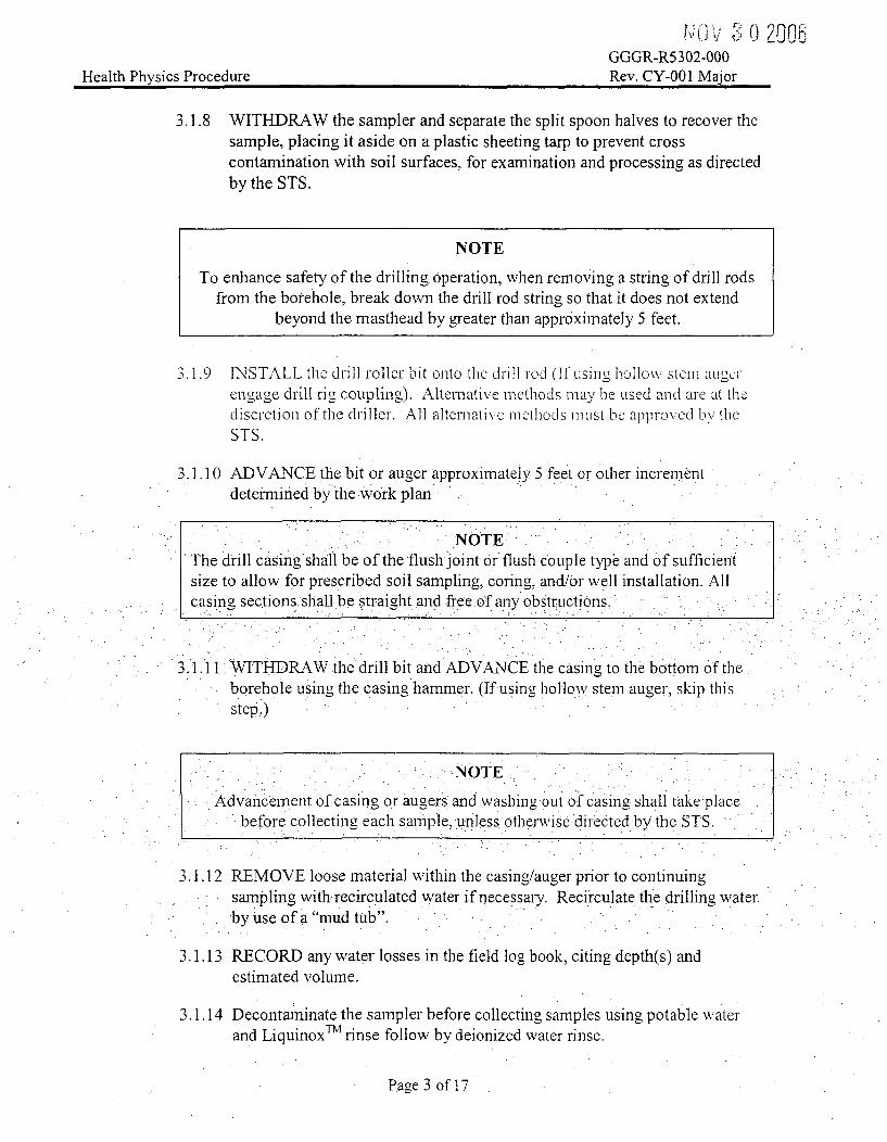
GGGR-R5302-000Rev. CY-001 MalorHealth Physics Procedure
3.1.8 WITHDRAW the sampler and separate the split spoon halves to recover thesample, placing it aside on a plastic sheeting tarp to prevent crosscontamination with soil surfaces, for examination and processing as directedby the STS.
NOTE
To enhance safety of the drilling operation, when removing a string of drill rodsfrom the borehole, break down the drill rod string so that it does not extend
beyond the masthead by greater than approximately 5 feet.
3.1.9 INSTALL the drill roller bit onto the drill rod (If uSing hollow stem S Iucrengage drill rig coupling). Alternative methods may be used and are at thediscretion of the driller. All alternative methods must be approved by theSTS.
3.1.10 ADVANCE the bit or auger approximately 5 feet or other increment
determined by the work plan
NOTEThe drill casing shall be of the flush joint or flush Couple type and of sufficientsize to allow for prescribed soil sampling, coring, and/or well installation. Allcasing sections shall be straight and free of any obstructions.
3.1.11 WITHDRAW the drill bit and ADVANCE the casing to the bottom of theborehole using the casing hammer. (If using hollow stem auger, skip thisstep.)
NOTE
Advancement of casing or augers and washing out of casing shall take placebefore collecting each sample, unless otherwise directed by the STS.
3.1.12 REMOVE loose material within the casing/auger prior to continuingsampling with recirculated water if necessary; Recirculate the drilling waterby use of a "mud tub".
3.1.13 RECORD any water losses in the field log book, citing depth(s) andestimated volume.
3.1.14 Decontaminate the sampler before collecting samples using potable waterand LiquinoxTM rinse follow by deionized water rinse.
Page 3 of 17

NOV 3 0 20o6GGGR-R5302-000Rev. CY-001 MajorHealth Physics Procedure
3.1.15 REPEAT steps 3.1.4 through 3.1.14 until target depth is attained or bedrockis encountered.
NOTE
If an obstruction is encountered during boring, the casing shall be advanced eitherpast or through the obstruction by drilling or mechanical fracturing. If the
obstruction is bedrock, a rock core may be taken at the direction of the STS.
3.1.16 IF drilling must continue into the bedrock, THEN replace the roller bit orauger with a rock cutting tool/bit and continue drilling.
3.1.1 7 Upon reaching the target depth, REMOVE all drill rods and down-hole toolsfrom the borehole.
3.1.18 Upon completion of drilling deep bedrock borehole locations, or if drillingdeep bedrock boreholes is interrupted for more than 24 hours, a flexible, linerwill be installed within the entire length.of the deep bedrock.borehole tominimize hydraulic communication between water bearing fractures atvarious depths.
3.1.19 RETAIN all drilling fluids as IDW and dispose as directed by the STS.
3.1.20 SAMPLE the IDW for.SOCs or COCS as-directed by the STS.
3.1.21 IF the IDW does not need to be disposed as radiological or regulatedchemical wastes; THEN place in the ihmmediate area surrounding themonitoring well (i.e., the point of generation).
3.2 Monitoring Well Installation
NOTE
Field conditions that are not addressed by the following sequence may exist.Alternative sequences are allowed at the direction of the STS. All deviations are
to be documented in the field log.
3.2.1 REMOVE borehole liner, if present.
3.2.2 MEASURE the borehole for total open depth with a tape measure.
3.2.3 IF the borehole has advanced to a depth greater than that of the well to beinstalled, THEN measures shall be taken to fill the borehole to the requireddepth, with appropriate fillmaterial (e.g., sand, grout or bentonite) asdirected by the STS.
Page 4 of 17

GGGR-R53•2-00 ' L'00DRev. CY-001 MajorHealth Physics Procedure
3.2.4 INSPECT well materials for integrity and condition. If needed, steam cleanwell materials prior to installation in the borehole.
3.2.5 INSTALL the well screen and riser pipe to the bottom of the borehole.Assemble the well screen and riser pipe as they are lowered into theborehole. As the assembled well is lowered, care shall be taken to place thewell in the center of the borehole.
NOTE
In no case shall the sand filter pack be longer than approximately 1.5 times thelength of the screen. A nminimum 1-foot thiclk layer of very finc sand may be
placed immediately above the well screen sand pack. This layer is designed toprevent the infiltration of sealing components (bentonite or grout) into the sand
pack.
3.2.6 FILL the.annular space surrounding the screened section of the monitoringwell and at least 2 feet above the top of the screen with appropriately gradedclean sand. As sand filter packing is being installed, retract theaugers/casing in a maimer that assures the sand is containedwithin theannular space: above the bottom of the lead auger or casing.: Use a tremiepipe to install the sand filter packing if required by field conditions.
NOTE
The purpose of the seal is to provide a barrierto preferential pathwvays for verticalflow of water in the annular space between the borehole and the. well. Bentonite is
used because it. is practically chemically inert, and in water, it swells by severalvolumes to form a seal that will not crack unless dehydrated.
3.2.7 FORM a seal using coarse granular bentonite chips or pellets by slowlypouring a minimum 2 foot thick seal immediately above the filter packmaterials in the annular space betweenthe borehole and the monitoring Nvell.
nhstallation of any grout above the bentonite seal shall be delayed at least 30minutes to allow hydration/expansion of the clay. If the vyell screen islocated below the water table, then a bentonite grout may be tremied to thedesired depth in lieu of pellets.
3.2.8 Log the top and bottom depths of the seal in the field log book.
NOTE
In situations where the monitoring well screen straddles the water table, the sealmay be in the unsaturated zone and bentonite may not seal effectively due to
desiccation.
Page 5 of 17

GGGR-R5302-000Health Physics Procedure Rev. CY-001 Major
3.2.9 IF the monitoring well screen straddles the water table, THEN install thebentonite seal and hydrate with several 5-gallon containers of water.
NOTE
Drill cuttings, even those known not to be contaminated, shall not be used asbackfill material.
3.2.10 Backfill the remaining length of borehole (while withdrawing the'wellcasing) with cement/bentonite grout to within 2 feet of the ground surface. Atremie pipe shall be used to install the grout to prevent voids.
3.2.1 1 MEASURE the depth of the stabilized wvater level.
3.3 Well Development and Completion
3.3.1 Following well installation, the well shall be developed by agitation with asurge block and bailing or pumping to remove fine-grained particles fromthe filter pack and increase the hydraulic communication With theaquifer.
3.3.2 PERFORM well acceptance tests in accordance with Attachinent 1.
3.3.3 INSTALL a steel guard-pipe or road box. around the well riser pipe inaccordance with the specifications on Attachmrent 1 or other configuration atthe direction of the STS.
3.4 Documentation of Monitoring Well Installation.
34..1 All pertinent.data shall be recorded in the field log and later transferred to a-.monitoring-well detail report and/or monitoring well construction diagram.
3.4.2 Well. locations.shall be referenced in theGIS system.
3.4.3 Document the screen and riser pipe materials, diameters of the components,screen slot size, type and thickness of the sand pack, thicknesses andltypesof grouting or seal materials.
3.4.4 Document the length of the riser above grade (if used), length of screen, ... .
l.ength of riser pipe;. total length of well, and depth to stabilized ground waterlevel in both the field log book and appropriate forms/diagrams.
3.4.5 Coordinates and elevations of the top of the monitoring well, protectivecasing and ground surface elevation will be determined later by survey.
4.0 REFERENCES
4.1 Haddam Neck Plant License Termination Plan, current revision
4.2 RCRA Quality Assurance Project Plan for Connecticut Yankee Atomic PowerCompany, Haddam Neck Plant, current revision
Page 6 of 17

NOV 2ý ,.) .0JGGGR-R5302-000
Health Physics Procedure Rev. CY-001 Major
4.3 NUREG-1575, Rev. 1/EPA 402-R-97-016, Rev. 1/DOE/EH-0624, Rev. 1; MultiAgency Radiation Survey and Site Investigation Manual (MARSSIM) August2000
5.0 ATTACHMENTS
5.1 Attachment 1 - Well Specifications and Acceptance Criteria
5.2 Attachment 2 - Checklist of Actions and Precautions
5.3 Attachment 3 - Example of a Borehole Log
5.4 Attachment 4 - \Vell Drilling Terminolo-v rind Definitions
Page 7 of 17

NOV 83 0 )06GGGR-R5302-000
Health Physics Procedure Rev. CY-001 Major
6.0 BASIS
6.1 MARS SIM methods must be utilized to design and implement the site LicenseTermination Plan (LTP). Section 5.3.3.2 "Land Area Surveys" of the MARSSIMmanual (Reference 4.3) describes the subsurface soil sampling requirements forcharacterization surveys. Accepted alternative methods are provided in the RCRAQAPP (Reference 4.2).
6.2 MARSSIIM methods must be utilized to design and implement the site LicenseTermination Plan (LTP). Section 5.3.3.3 "Other Measurements/SamplingLocations" of the MARSSIM manual (Reference 4.3) describes the ground watersampling and monitoring requirements for characterization surveyS. Acceptdeialternative methods are provided in the RCRA QAP P (Refercnce 4.2).
6.3 Procedure GGGR-5300-000 (RPM 5.3-0) "GrouId Water Monitoring Program(GWMP) requires the Data Quality Objective (DQO) process must be utilized inthe selection of the site for a new monitoring wvell installed under the LTPprogram. Wells installed under the RCRA program must comply with the RCRAQAPP. The installation requirements of both pr0grams compliment each other,therefore data from all wells may be used to support both programs
6.4 :-A Contract Driller must be made aware of the scope of work, well specifications,well acceptance criteria in order to submit a bid package to perform the work.
Page 8 of 17

C•GRV_0d 02006GGGR-R53eOvY-001aRev. CY-001 MajorHealth Physics Procedure
7.0 CHANGES
Revisions made to this procedure reflect the long-term groundwater monitoringrequirements of the NRC and the CTDEP.
Page 9 of 17

,ot~ *i C0GGGR-R5302-000
Health Physics Procedure Rev. CY-001 Major
ATTACHMENT I
Well Specifications and Acceptance Criteria
Section A - Specifications for the Borehole
The diameter of the borehole shall be a minimum of 4 inches. This will allow sufficient annular space toinstall a filter pack, bentonite and/or Yrout seal.
2 In bedrock, the borehole can be a minimum of 3 inches in diameter around the screened portion of theborehole.
Section B - Specifcations for Split Spoon or Other Samnpling, During Drilling
An outside diameter split spoon up to 3.75 inches.
2 An 18 to 24-inch sample capacity.
7 Equipped with a basket-type retainer for loose-soil sampling, if rcqui rd. Eqiippcd with fppcr-v:i v, if
required.
Section C - Specifications for Riser Pipe and Screens
Riser pipes and screens shall be Polyvinyl Chloride (PVC) schedule 40. with a maximumn outside diameterof 2'/2 inches.
2 Screens shall have a slot size of 10 (e.g., 0.010 inch).
3 Length of screens will normally be 10 feet, but inay, range from 5 t6 20 feet; as needed by field conditions.In no case shall a screenbe less than 5 feet in length.
.4 The connections between screens and pipe shall be threaded flushjoints., with end caps placed onthebottom of each well screen, or plugged with an approved material.
Riser pipes shall be capped with a removable. lockable cover or plug.
6 Riser pipe and screens shall be transported to the site in sealed plastic wrappings, provided by themanufacturer, which are to be removed only at the time of installation.,
7 No glue; solvent or anti-Seize compound shall be used on the joints.
Section D.- Specificationsfor Protecting the Finished Well
I In high traffic areas. metal road boxes completed at grade level will be required as penranent protection fora well.
2 In unimproved areas, a protective metal casing extended to approximately 3 feet above the ound surfacewill be required to finishthe surface installations.
3 If a raised casing is used, drain holes are required at or near grade to prevent accumulation of standingwater.
4 All wells will be secured with keyed alike pad locks. If not possible, separate keys may be necessary.
Page 10 of 17

GGGR-R5302-000Health Physics Procedure Rev. CY-001 Major
ATTACHMENT 1 (cont.)
Well Specifications and Acceptance Criteria (cont.)
Section D - Specifications for Protecting the Finished Well (cont.)
5 . The raised casing will be vented in an area protected from precipitation. Road box installations will not bevented.
6 For finished well protection (i.e.., flush mounted or riser casing), the surface materials around the wellshould be dug out to form an approximate 2 by 2 foot square to a depth of approximately 24 inches andfilled with concrete.
7 If well is located in anl unpaved area, then a fornm consisting of 2 by 4 lumber shall b- constrctc ted aroundthe perimcter of the 2 by 2 foot square prior to placement of the concrete.
8 If in a paved area, a 2 by 2 foot square will be saw cut tharough the existing pavemcnl and no form w, ill benecessary.
II The surface around each well shall be finished with concrete to secure the guard pipe or road box in place,prevent surface drainage from entering the well boring directly, promote surface flow away from the well,and to preclude damage due to frost action.
12 The raised protective pipe should be sunk at least three feet below ground surface, into the concrete-surfaceseal.
13 The road box shall include a watertight cap inside the riser pipe to prevent surface water from entering thewell.
'14 All complete.d.wells will have identification numbers clearly marked on the road box or guard pipe.
..Section .E- Well Acceptace Criteria
S1 •The borehole will-be checked for total open depth, and extended by further drilling or. shortened. ifnecessary, before any well construction materials are placed.
2 Water level will be checked to assure that the positions of well screen, filter pack and seal, relative to water. level. conform to requirements.
3 The depth to the top of each layer of packing (i.e.. sand, bentonite, grout. etc.).will be verified and adjusted.if necessary to conform to the direction of this guidance before the next layer is placed.; .
4 A minimum 3.foot length of pipe with a diameter of no more than V2 inch smaller than the inner diameter ofthe riser and screen will be lowered to the bottom of each well screen to check well alienment and confirmthat no small radius bends or obstructions are present.
5 A minimum 3 foot length of pipe with a diameter of no more than. /2 inch smaller than the diameter of theopen borehole in the bedrock borings will be lowered to the bottom of the well using a wire line and thedrill rig winch to check well alignment and confirm that no offsets or obstructions are present.
Page 1l of 17

GGGR-R5302-000Health Physics Procedure Rev. CY-001 Major
ATTACHMENT 2
Checklist of Actions and Precautions
Section A - Preliminaries
The DQO process used to select the location of a new well must be documented in a work plan for wellsinstalled to support the LTP program.
The proposed excavation locations shall be marked.
Ensure that well specifications and well acceptance criteria (Attachment 1) are incorporated into theStatement of Work (SOW) for the selected Contractor Driller, if necessary.
J .Job Safety Analysis has been perforied. 'At a minimum the itcms in scct on:; D3 dtroucha E should be:included in the analysis.
Section B - Eneiigized Underiground Utility lta-ard
During decomm'nissioning, obtain approvals for a "Site Excavation Permit" in accordance with procedureGGGC-00023-002 "'Excavation and Backfill and Stontwater Erosion Control". This technical evaluationensures that all responsible disciplines have reviewed the drill holes locations and that reviews ofappropriate mechanical, electrical and civil drawings, have taken place to ensure that buried utilities areavoided.
Following decotnmissioning, Call Before You Dig (1-800-922-4455) is notified at least three working daysprior to the start of drilling. If drilling within the Industrial Area, it may also be necessary to notify theCL&P underground utility representative..
_ I independent subsurface interference locition.personnel have scanned the-proposed driiling;lcations andmapped any underground obstacles.
A__ 'A minimum 4-foot deep hole will be excavated with hand tools at the proposed location of each monitoringwell and deep bedrock boring to clear the area for underground utilities before mechanical drillingequipment is advanced below the ground surface, with the exception of those locations where extensive soiland/or bedrock remediation has been completed.
* Section. C-.- O1erhead Power Transmission Line Hazards
___ " A minimuim distance of 10feet shall be maintained from an)y overhead service or electrical distribution line* to the closest point.on any drilling equipment. A service line has a nominal phase-to-phase voltage of
220/480 volts. An example of a service line is~the line ber, een the pole and aresidence. A distribution lineis up to 50,000,volts, and is typically 3-phase mounted on high-tension supports.
A minimum distance of 13 feet shall be maintained from any energized overhead transmission conductor,with a nominal phase-to-phase voltage of 115,000/138,000 volts, to the closest point on any drillingequipment. An example of this. voltage includes the power lines supplying the plant, which are overhead inthe RCA 115kv yard at the south end of the Industrial Area.
If an overhead electrical hazard or a risk of lightening strike is present, the drill rig chassis and otherauxiliary equipment shall be properly grounded prior to drilling.
Page 12 of17

GGGR-R5302-000Health Physics Procedure Rev. CY-001 Major
ATTACHMENT 2 (cont.)
Checklist of Actions and Precautions to be Included in the WP&IR
Section D - Radiological, Chemical and Fire Hazards
If subsurface soil or ground water is known to be or suspected to be contaminated with radiological SOCs,contact the HP Operations Supervisor.
Provisions must be made for the retention of drilling fluids and cuttings (e.g., mud tub). Do not drain waterto a floor or yard drain on the property.
Obtain product hazard information (e.u.7 MSDS) to use crillinm, fluids such as bcntonite or Revcr.. flltrpack material such as quartz sand or -ravel-. well seali .u niateria such as benlon ite nr fine sand andecontamination supplies such as Liqnumax surfac ta'nt.
Proper fire safety precautions must be observed relative to flammable substances (gasoline, propanc, etc.).This includes not smoking near the drilI ri-. Gasoline cans must be of an approved type, closed when not inuse. and stored away from drilling activities.
Section E -General items.
Equipment should only be operated in an area where the ground surface is stable, clear, and level.
____Perform a daily check/test of all safety devices. This.includes atest of the emergency-kill switch and avisual check of drill rig equipment for any defects, excessive wear, loose bolts, low fluid levels, leakyconnections and chafed hoses.
•-Section F Follow.,on, items -
_____ A pre-job briefing is performed.
___ Specify any interfacing procedures that will be utilized in conjunction with the performance of the worksuch as Chain of Custody and Sample Packaging and numbering methods-
Page 13 of 17

NJov 2 0 _6GGGR-R5302-000Rev. CY-001 MajorHealth Physics Procedure
ATTACHMENT 3Example of a Borehole Log
FEB2z ~iggRq
Project- Boring No.
Page of
Driller P _ o _
Locgec by Dcte(s)
Elevoion, Depth Ground Wcter Depth
LoCs ,,on ___
O If~~sc~rnw~~si
4
2:1 __________ I ___________________________
.4
J
3
3
Page 14 of 17

GGGR-R!i- 0 0Health Physics Procedure Rev. CY-O01 Major
Attachment 4
Well Drilling Terminology and Definitions
Air Rotary Drill - A type of drill rig that utilizes air to lift cuttings from the borehole. Acompressor provides air that is piped to a swivel hose connected to the drill pipe that, in turn, isconnected to a down-hole hammer. The down-hole hammer pulverizes the rock and thecompressed air lifts the rock fragments to the surface.
Anvil - That portion of the drive-weight assembly which the hammer strikes and through whichthe hammer energy passes into the drill rods.
Auger - A type of drill bit that penetrates hard or packed solid materials or soil. It consists ofsharpened spiral blades attached to a hardened metal central shaft.
Bentonite - A non-toxic processed clay material. It has a ,rcat affinity f0or fresh w\atcr and, whenhydrated, wiii increase its volume more than seven times. Bentonite is conmnonly. used to plugboreholes, and prevent hyidraulic communication of discrete aquifers and entry of surfacecontaminants.
Borehole Log - The record of geologic units penetrated, drilling progress, depth, water level,sample recovery, volumes'and types of materials used, and other significant facts regarding tlhedrilling of an exploratory/characterization borehole or well.
Call Before You Dig (CBYD) -A statewide, one-call notification system that providesexcavators with the ability to infornm multiple owners and operators.of underground utilities ofproposed excavation. This is initiated by a telephone call to 1-800-922-4455. Public Act 87.71of the Connecticut State Statutes requires an advance notice of at least two full working days.prior to commencing excavation. Excavation notices expire at the end of 30 days fioni the datethat notice was provided. For proposed locations inside the Protected Area, the utility l1catingfunctions are performed by CL&P. The notification system will issue a "Location RequestNumber" for the proposed excavation..
Casinig- A pipe that is installed within the borehole to couinteiact caving, to advance theborehole, or to isolate the zone being monitored..
Cathead - The rotating drum in a rope-cathead lift system around which the operator wraps arope to lift and drop the hammer by successively tightening and loosening the rope around theturning drum.
Drill Rod - A drilling tool used to transmit downward force and torque to a drill bit whiledrilling a borehole.
Drive Weight Assembly - A device consisting of a hammer, hammer fall guide, the anvil and anyhammer drop system.
Page 15 of 17.

Sv'3 0 "1006GGGR-R5302-000
Health Physics Procedure Rev. CY-001 Major
Filter Pack - A body of granular material (such as clean sand) used in a monitoring well to act asa non-clogging filter or a formation stabilizer. It is typically positioned between the well screenand the borehole wall.
Flush Joint or Flush Coupled - A characteristic of well casings or risers. These well pipes havethreaded ends such that a consistent inside and outside diameter is maintained across the threadedjoints or couplings.
Grout - A low permeability material placed in the annulus of a well to maintain the alignment ofthe casing and riser and to prevent movement of ground water or surface water within the annularspace. Grout consists of a cement/bentonite mixture in the proportion of one 94 lb. bag ofPortland cement, 3 to 5 lbs of pow'dered bentonite and 6.5 lullons of pota:lr lvaitlor. Grout shoulIbe used before it sets (typically wvithin one hour- otmiing).
Haminer - That portion of the drive weight assembly consisting of the impact weight that issuccessively lifted and dropped to provide the energy that accomplishics the snmplig andpenetration.
Hanmner Drop System - That portionl of the drive weight assembly by which the operatoraccomplishes the lifting and dropping of the hammer to produce the blow.
Hammer Fall. Guide - The part of the drive weight assembly used to guide the fall of thehammer.
Investigation Derived Waste (ID W) - The waste material generated during a drilling activity. Itincludes the soil/rock spoils from a drill hole brought to the surface by an auger or coring bit as:well as waters circulated within the bore hole for bit cooling and other. liquid discharges. TheIDW is contained until the analytical sample results are known. If the analytical sample resultsindicate that contamination is present, then the IDW is appropriately classified, labeled and
• disposed. Otherwise, it can be returned to the environment.
Job Safety Analysis (JSA) - A method of identifying potential safety hazards for a particular jobevolution and how they will be controlled prior to job perfoniance..
Mast - A drill rig appurtenaice used for supporting the crown block, top drive, pull-dowfn chains;drill rods, hoisting lines, etc.
Multi-Cased Well - A well constructed by installing suecessively smaller diameter casings thatterminate at grade level within larger outer casings. The smallest diameter casing extends to thegreatest depth (bottom of the well).
N-Value - A quantitative derivative of the blow counts required to drive a split spoon samplingassembly to full penetration into the soil matrix. The number of blows required to drive the splitspoon is recorded for each 6 inch segment of the 2 foot sample interval (four segments). The N-value equals the sum of the blow counts for the second and third segments. The N-value is ageological parameter of soil penetration resistance used when characterizing local soil horizons.
Page 16 of 17

NOV 2 0 26DGGGR-R5302-O00
Health Physics Procedure Rev. CY-001 Major
Personal Protective Equipment (PPE) - PPE is safety equipment that must be worn to protectindividuals working in hazardous environments. The equipment required for a particular jobevolution may consist of head, eye, ear, hand, and foot protection as well as fall protection andnon-radiological respiratory protection.
Pre-Job Safety Briefing - A method to communicate the identified hazards and the controlsapplied to those hazards to the workers before they engage the work.
Radiologically Controlled Area (RCA) - An area where access is restricted and the performanceof work is controlled for the purpose of protecting individuals from exposure to radiation and/orradioactive materials.
Radiation WJork Permit (R IVP) is a document that identif ies tile job, rad Lion hazrds, recu redprotective controls, and special instructions associated with working in an RCA. RWPs alsocontrol access to RCAs.
Riser - A pipe extending from the well screen to or above the ground surfatcC.
Sampling Rod.- A tool that will connect. the drive weight assembly to.the sampler. Drill rods areoften used for this purpose.
Single-Cased Well .A monitoring well constructed with a riser but without an exterior casing.
Split Spoon or Split Barrel - A sampling device that consists of two halves of a cylindricalbarrel with.a drive shoe, a threaded top cap, and an optional liner, driven into the soil. at the.,bottom of the borehole using the drive weight assembly: When the split spoon isemoved fromthe ground, the barrel halves are opened and the sample is removed.
Treinie Pipe - A tool used to transport filter pack and/or annular sealant materials from thegr und surface into the borehole annulus or between casings and/or riser pipe of a monittring "Well .
Vented Cap - A cap with a small hole that is installed on top of the riser.
Well Screen - A filtering device used to retain the primary or natural filter pack. usually acylindrical pipe with openings of a uniform nwidth, orientation, and spacinig.
Page .17 of 17

OCT 26 2005GGGP-00001-007Rev. CY-009
Administration
CONNECTICUT YANKEE ATOMIC POWER COMPANYHEALTH PHYSICS
Ground Water Sample Event Planning and Data
Management (RPM 5.3-3)
GGGR-R5303-000
Rev. CY-002 Major
VERIFY MOST RECENT REVISIONAGAINST MDI:
INITIALS DATE
Review: Date:/-In49pendent Satety Reviewer
Approval: Date:Designated Deconirssioning Manager
Effective Date:
Responsible Individual:Brian Couture
GGGP-00001-007, Rev. CY-009 Attachment B

Health Physics Procedure GGGR-5303-000Rev. CY-002 Major
Ground Water Sampling Event Planning and Data Management (RPM 5.3-3)
1.0 OBJECTIVE
1.1 This procedure provides instructions to prepare a Groundwater Sampling EventPlan (GWSEP) to support the groundwater sampling that will be ongoing at theHaddam Neck Plant through license, termination and siteclosure. Sample eventplanning and data management are integral and important steps in projectexecution. GWSEPs may not be required for each event, but instead may refer tothe appropriate work plans and procedures needed to collect defensible data.
2.0 PEQU ISITES
2.1 GWSEPs will be sufficiently detailed to document completion of applicablearoundwater monitoring requirements to support Haddarn Neck Plant LicenseTermination and/or the. Lon- Term Gro1idvatr N'lonr it, P -lan- to d,,Jos.-rLV2: compliance with CTDEP RSRs (Work:Plans)........
2.2: This procedure will specify the Data Quality Objectives (DQOs) for general andrepetitive types of well sampling activities or refer to: the appropriate documentsthat list the DQOs.
2.3 Each ground water sampling event will be controlled by a distinct GWSEP. Thisplan will comply with the appropriate Work Plans.
3.0 INSTRUCTIONS
3;1 PREPARE the GWSEP
3.1.1 During decommissioning, OBTAIN a WP&IR number to be used for theground water sarnpling event activities if necessary.
3.1.2 During decommissioning, OBTAIN a Radiation Work Permit (RWP) ifnecessary.
3.1.3 INITIATE the GWSEP by compiling the appropriate information for allapplicable work plans to integrate the field effort.
3.1.4 PREPARE a consolidated table that lists all sample analyses required foreach location. The table shall include screened interval, approximatewater elevation, and required pump type.
3.1.5 PREPARE a table to list bottle (volume) requirements, preservationrequirements and hold times.
Page 1 of 14

_j tiJ:
Health Physics Procedure GGGR-5303-000Rev. CY-002 Major
3.1.6 COMMUNICATE with the laboratory in advance of the sampling event toensure that the bottle inventory is sufficient and ensure the laboratory isprepared to receive the samples.
3.2 OBTAIN review and approval signatures for the GWSEP.
3.3 During decommissioning, if necessary, TRANSFER the approved GWSEPpackage to the Groundwater Monitoring WP&IR work tracking package.
3.4 During decommissioning, if necessary, INITIATE/COMPLETE field samplingactivities uinder control of the WP&IR work package.
.•.5 Data cana~ement3.5.1 All samples vill be logged into a sample tracking system. If such a
database is not available, then Attachment 7 GWSEP Sample Tracking and
include time and date of sample, analyses requested, bottle andpreservation requirements; sample delivery goup, and shipment date. The
database may also be used to electronically generate thle Chain of Custody(CoC).
3.5.2 REQUEST that the laboratory provide all data in an acceptable ElectronicData Deliverable (EDD). ENSURE that the formats comply with BOTHthe LTP groundwater requirements and the RCRA Program requirements.Two.separate EDDs may be delivered for. each event...
3.5.3 When field sampling activities are complete, PLACE all field samplingdata and notes (10og sheets) into a discrete and distinct hard copy folder inthe Project File. Electronic files will be submitted to the GroundwaterTechnical Lead.
3.5.4 MAINTAIN all files in an openlworking status until all requested sample
analyses results are obtained from the laboratory and the sample eventreport has been finalized.
3.5.5 DOCUMENT in the sample tracking database or on Attachment 7 the dateand time that sample results are received from the analytical laboratory.
3.5.6 At the end of each event, FORWARD all field sample data and labanalytical results to the Groundwater Technical Lead for review to assurethat the DQOs have been attained for each sample.
Page 2 of 14

Health Physics Procedure GGGR-5303-000Rev. CY-002 Major
.3.5.7 REVIEW the lab analytical results. At a minimum, this review shouldensure that Required Detection Limits (RDLs) have been achieved (seeAttachment 5). This review should also include an evaluation of sampleanalysis completeness, precision and accuracy. Chemical constituents willbe validated in accordance with the RCRA Quality Assurance Project Plan(QAPP). The data review may be documented on Attachment 7 or in*memo format to the Groundwater Technical Lead.
3.5.8 UPLOAD al!data to a protected server. Data may be stored andmanipulated in individual. files, but both the raw and validated data mustbe loaded for long term storage. Data evaluation for the RCRA program.(incl1-ding RSR compliance monitorinl)wIQvill be Conducted usg.GTS. C For .b.oth. dt diologicI1 a annd chem i cai COf tit.i aiiucll di< cl. to "11C SQLSor!',:r." . .Eq nixV ent Sygtel s riS 1,eI LhuR d provicd th dI -h , ilt L-ur :ir, , 11i-r c r c fdand any changes automatically tracked.
5.3.9 . L)(tt-m,• eco fIIIIlissionlng,.ittcc ssaT~r... -"
- _.9 Uurr do II C IN.L\(iL J. v L Ll -coap tcd L,._i c. Li,
package fion the Groundwater Monitorinn WP&TR work package.DOCUMENT the transfer in the WP&IR Dounment Log. Afterdecolmmissioning, all files will be maintained by the Groundwater ProjectLead.
3.5.10 During decommissioning, RETURN the completed and reviewed sample
data into the appropriate working GWSEP file. After decommissioning,all files will be.managed. by..the Groundwater Project Lead.
3.5.11 After sample analyses results are obtained and reviewed, PREPAREreports as required in the specific Work Plans.
4.0 REFERENCES
4,1 Ground Water Monitoring Program (RPM 5.3-0), current revision
4.2 Ground Water Monitoring Program Quality Assurance Plan for the ConnecticutYankee Decomnissioning Project, current revision.
4.3 Ground Water Level Measurement and Sample Collection in Monitoring Wells(RPM 5.3-1 ), current revision
4.4 Groundwater Monitoring Plan to Support CY License Termination Plan,CH2MHill, current revision.
4.5 Long Term Groundwater Monitoring Plan to Demonstrate Compliance withCTDEP RSR, MACTEC, current revision.
4.6 RCRA Quality Assurance Project Plan, MACTEC, current revision.
Page 3 of 14

NV d LHealth Physics Procedure GGGR-5303-OO0Rev. CY-002 Major
5.0 ATTACHMENTS
5.1 Attachment 1 - Ground Water Sampling Event Plan Cover Sheet
5.2 Attachment 2 - Individual Well Sampling Plan
5.3 Attachment 3 - Ground Water.Field sampling Data Quality Objectives (DQOs)
5.4 Attachment 4 - Ground Water Sample Volume, Container, Preservation, and HoldTime Requirements
5.5 Attaclhlent 5 - Ground Water Radiolo,4cal SaInplinm Protoc0:is
D5.0 1Attachniclat: 6,- Ejuip)Ment. PIc-StaL in uIdII,-pC -I~IcIti\y c -Ur1
5.7 Attachunent 7 - GWSEP Sample Tracking and Data Quality Assessment
-ý LLLICIIIIIC IIL -:r,'k- iKCJI ~ .AIILI\ .SI K IUF L .U (J •0 I I! 1 pl
Page 4 of 14

JUV i v1C,Health Physics Procedure GGGR-5303-000
Rev. CY-002 Major
6.0 BASIS -
Items below that are specific to site procedures will be implemented throughdecommissioning.. After license termination, all sampling will be conducted inaccordance with the RCRA QAPP.'
6.1 Groundwater Monitoring activities must be conducted using approved site orvendor procedures that assure sarnple integrity and qualityof measurement.
6.2 The G\VM P (RPNVl 5.(3-0) and tlhe G\VMP.QAP r-eqUire [he clt:thlishinhm tii oCt"- .(-i \.S E P tnt provides the di mre •or- Wr .L[,ti Q t Lv .,K-s: - it.(D. . ).
6.3 Data Quality Objectives (DQOs) and the DQO process are specified in Referenceb~ I U,. 1., ... . .
being assessecd.
6.4 Each Ground Water Sampling EventPlan (GWSEP) constitutes the Work Plan(WP).
6.5- Ground Water Sampling Event Plan (GWSEP) documents shall be periodicallytransferred to nuclear records in conjunction with the semi-arnual reportingfrequency.
Page 5 of 14

Health Physics Procedure GGGR-5303 0 URev. CY-002 Major
7.0 CHANGES
Revisions made to this procedure reflect the long-term groundwater monitoringrequirements of the NRC and the CTDEP.
Page 6 of 14

d JUHealth Physics Procedure GGGR-5303-OO0
Rev. CY-002 Major
Attachment I
Ground Water Sampling Event Plan Cover Sheet
Reviews and Approvals
Ground Water Sampling Event NumberThis Ground Waater Sampinrn g Evei t Pan (GWSEP) incluteslthe follow items:
V~~~i .1 .I ... il olo"IQ tn
I'S -. . ..
.. 5 P ••.:o Attach1ment I- c ) .- •
pagye of Attachament 2 Ground Water Field samfpling Data Quality Objectives (DQOs)
Tiie Requirements
page of Attachment 5 Groutnd Water Radiological Sampling PrOtocols
pages of Attachmient 6.Equipment'Pre-Staging id Sample Preservative Reqzi'emnents
pages of Attachment 7 G WSEP Sample Tracking and Data Quality Assessment
other supporting documents (e.g., procedures list by nuniber)
This GWSEP in its entirety has been reviewed and approved by the following individuals:
Prepared by:Enviro0nental Specialist Date
Approved by:_Groundwater Technical Lead Date
Approved by:Technical Support Manager Date
Approved by:Site Closure Manager Date
Page 7 of 14

Health Physics Procedure'• V Uj . UUU
GGGR-5303-000Rev. CY-002 Major
Attachment 2
Individual Well Sampling Plan
GWSEP #:
Well/Sample ID #:
Analysis Type:.
TOTALS:
Approved Procedure References and/or Items to Note During Sampling:
Anticipated Exceptions to Field sampling Parameters:
Possible Contingencies:
NOTE: All samples collected should meet the DQO protocols specified on Attachrilents 3, 4 or5. Exceptions shall be noted on Attachment 7.
Page 8 of 14

Health Physics Procedure~j 0 'f'u
GGGR-5303-000Rev. CY-002 Major
Attachment 3
Ground Water Field Sampling Data Quality Objectives (DQOs)*
I. Field sampling protocols to ensure the collection of representative ground watersamples.
1. 1 Well Purging - Purge the well at a rate that maintains a water level drawdown ofless than 0.3 feet from the initial measured static water level. If the pump rate-results i a drNwdown.of greater than 0.3 feet. the \v ell sliould be puimped
-intermittently so dravdown.does not exceed 0.3 Feet.Jnt ... it: so :N cc....
1.2 Field Parameters - Monitor the listed field parameters after one pump and dischargetube volume is clischareed. Monitor usine an appropriate measurin' device. such as
device when well purging:is comnplete. Well purging is complete when thle fieldsarnpling water quality parameters have stabilized. ile when 3 consecutive readincs
taken at 3 to:5 minute intervals are withlin the following limits:
" Turbidity less than 1:5 NTU with avariability of less than 10% (for tui b:I iditvy 'readings greater than I NTU)
SSpecific Conductance less than 3% variability
* Dissolved Oxygen (DO) less than 10% variability
* Temperature less than 3% variability
* PH (+/- 0.1 units)
* ORP/Eh (+/- 10 millivolts)
• For the purpose of assuring representative sample collection required to demonstrate compliance with
the License Termination Plan (LTP) or Water Quality Standards (WQS), a generic DQO is anacceptable approach to ensure data quality since these sample collection protocols are established by aregulatory entity.
Page 9 of 14

Health Physics Procedure-i u UUF2
GGGR.5303-000Rev. CY-002 Major
Attachment 4
Ground Water Sample Volume, Container, Preservation and Hold Time Requirements1
Analytical Minimum Sample P TI"nMaximumSuite " Volume Container ecique Holding Time
VOCs (2) 40-ml. Glass vial Acidify to pH<2 with VOC 14 days•___ grade HCI, cool to 4°CsVOCs 1"-liter ."A•amber glass Cool to,4°C 7/40 days(2.
Metals 500-mi ;Polyethylene Acidify to pl-[<? With reagent__ _ _ _ _ _ _ . •__ _ ..___•. _ .ii ___..... __. .. .. .P"i-adeHANO ... . .. . ..• " , -. A'd\ P1H<2 with reagent.-Mcrcuivals 500-11 Poly0tlcn c i. . 2 ddNO
grade HNO3 )8L'aV
Cvcmidk 1 -Pitc Poivc:Wcnc.!> AJdd N:'OHl tn v11>1 2 I--0v (
PCBs "-liter Amber glass Cool to 4"C .. 7/40-daysk->
T• .. 2-liter Am ber g AcidifVtopH<2 with reagent" 7 d'•TPH ~ ~ ~ ~ ~ ~ ~ ga H• I2tr.. me rs .. '.• •.".g- ... 7/40-dayss ... :. grade S 4, cool to 40C
iP esticides:, . ":.. . .i . • : , . . .. ;. .. ...• • ; ' .i: .:..."..: ..: . .:estcides, I-liter Amber glass: Cooto 14 0C . 7/40-dayst!).,.Hterbicae Ai. . . ..
Anions,Cations I -liter Polyethylene Cool to 40C Varies
Alkalinity 1-liter Polyethylene Cool to.40C. .14-days
•TDS/TSS I -liter Polyethylene Cool to 4°C 7-days
TOC 250-ml Polyethylene Acidify to pH<2 with reagentT"C" grade HiS0 4, cool to 4 0C "8-days
Total Uranium 1-liter Polyethylene Acidify to pH<2 with 20 ml 6-months
reagent grade HN0 3
Gross crif3, 4-liter Polyethylene Acidify to pH<2 with 20 ml 6-months^-isotopic reagent grade HNO 3 ________
Sf-90 4-liter Polyethylene Acidify to pH<2 with 20 ml"_•_reagent grade HNO3 6-months
HTDs 4-liter Polyethylene Acidify to pH<2 with 20 nil 6-nthsreagent grade HNO3 6_mnths
H-3, C- 14 1 -liter Polyethylene None, no headspace 6-niontlis
NOTES:
2
3
Generic DQOs are designed to satisfy sensitivity requirements of the License Termination Plan (LTP)or Water Quality Standards (WQS) are an acceptable approach to ensure quality data.Extraction within 7 days, analyses within 40 days.The mercury is drawn from the 500-mil metals sample.
Page 10 of 14

Health Physics ProceduretJ10 ,,
GGGR-5303-000Rev. CY-002 Major
Attachment 5
Ground Water Radiological Sampling Protocols ''
Groundwater(2) EPA Drinking Required(4) A ypa i
Radionuclide Water MCL(3 Detection Analysis Typical AliquotDCGL, (pCi/L) (pCiL) Limit (pCiL) Category Size (liter)
. ~ /L . Li i (p . • ..
Gross •- . 15. 3 GPC(a) 0.2:
Gross 3 . - " .5 4 . GPC I 0.2_______ ~~ K 00.J._ _ _
• U3 26080 20000 LSCC. ' 001U-14 360 2000 200>.: LSC ... 02
Mn-54 968 300 50 7-isolopic 2Fe-55 2616 2000 25 LSC 0.4C 0 -6 2Ni-63. .1260 50 15 LSC :0.4Sr-90 10 8 . 2 .GPC, LSC. . 1
Nb-94 270 109g 50 . . y-isotopic 2
Tc-99 1056 900-...."..... 15 LSC "0.125
* Ag-108m . 170 . . 44 : 20 yisotopic .2Cs-134 14 80 14 y-isotopic 2Cs-137 17 200 15 Y-isotopic • 2
. Eu-152 . 293 200 50: . ,y-isotopic 2
Eu-154 202 60 .50 y-isotopic .2
Eu-1 55 1300 600 50 J y-isotopic 2* Pu-238 0.60 15 0.50 a-isotopic 0.2
Pu-239 0.54 15 0.50 a-isotopic 0.2Pu-241 28.40 300 15 LSC 0.2
Am-241 0.53 15 0.50 at-isotopic 0.2
Cm-243 0.78 15 0.50 ct-isotopic 0.2
NOTES:
Generic DQOs are designed to satisfy sensitivity requirements of the License Termination Plan (LTP)or Water Quality Standards (WQS) are an acceptable approach to ensure quality data
2 Resident farmer scenario at 1 -mrern per year.
Beta/gamma emitters based on 4 mnRem per year dose equivalent limit. Values for Nb-94 and Ag- 108mcalculated in accordance with ICRP-2.
4 Minimum Detectable Concentration (MDC) designed to meet DQOsGas proportional counting
b EPA screening levelLiquid scintillation counting
Page I I of 14

Health Physics Procedure',u, 3 i 2riF1S
GGGR-5303-000Rev. CY-002 Major
Attachment 6
Equipment Pre-Staging and Sample Preservative Requirements
GWSEP #:
Special Equipment needs:
Sample Type Total Number Number & Type Preservative Preservativeof Samples o C tainers Volume (ml).pei
per sample. ona
TOTALS:
NOTES:
LF:PENN:STND:
MIX:ALL:
Gross a•3, 7-isotopicGross a03, y-isotopic and H-3Gross a/[3, y-isotopic, H-3 and boronGross a023, y-isotopic, H-3, boron and Sr-90Gross a/[3, y-isotopic, H-3, boron, Sr-90 and HTDs
Page 12 of 14

Health Physics Procedure GGGR-5303-000Rev. CY-002 Major
Attachment 7
GWSEP Sample Tracking and Data Quality Assessment
_ __ _ _._. _ _ [ _"
_______ _______ - _______ I. ______ I.. _______ I
NOTES:LF Gross a/I, ,y-isotopic
PENN Gross a/3, y-isotopic and H-3STND Gross a/p, y-isotopic, H-3 and boron
MIX Gross a/p, y-isotopic, H-3, boron and Sr-90ALL Gross a/. y-isotopic, H-3, boron, Sr-90 and HTDs
Page 13 of 14

Health Physics ProcedureI~j, &. . (0 F 6
GGGR-5303-000Rev. CY-002 Major
Attachment 8
Required Analysis Key for CYAPCO Ground Water Samples1
Ag- -10S1¢"4 14 V
Ni-63 4 4
Sl`-9()I .
.N b-94 . ' . .. .. . .- .. , ._ " . __: _. ,_.._. . _ __
Tcr99 'Cs- 1344 4____4444
Cs-137 4 4 "4 " 4 '4
Eu-152... 4 4 4Eu-,154 4 4... 4' 4 '
Eu-155 4 4 " :4 4 4Pu-238 4 -4 4
.Pu-239/240 4 " 4.4Pu-241 4 4 4
Am-241 42 "4 24 24 4 42
Cmn-243/244 ] 4 -4 ' I -_ _ _ _ _-
Notes:
All analyses performed to meet Required Detection Limits (RDL) specified in Attachment 5.2 There is no specific RDL for A-n-241 when reported by y-isotopic analysis.
Page 14 of 14

!1V tjC 20OCT 26 2005GGGP-0000 1-007Rev. CY-009
Administration
CONNECTICUT YANKEE ATOMIC POWER COMPANYENVIRONMENTAL
Groundwater Monitoring Program QualityAssurance Plan for the Connecticut Yankee
Decommissioning Project
ISC-GQP-00002-000
Rev. CY-002
VERIFY MOST RECENT REVISION.• AGANST AMI:
INITLLS DATE
Review:.
Approval:
Independent Safety ReviewerDate:_____________
Date: l1-' ,W6. 9Designated Decommissioning Manager
Effective Date: Ir-
Level of UseGeneral
GGGP-0000 1-007, Rev. CY-009
Responsible Individual:Brian Couture
Attachment B

Table Of Contents
I PROJECT MANAGEMENT ..................................................................................................................... I
1.1 B A C K G R O U N D ......................................................................................................... I1.1.1 Location and Property D escription ...................................................................... I1.1.2 Plant Construction and Operational History ....................................................... 21.1.3 Background of Connecticut Yankee Decommissioning Activities and the Role of This Plan toSatisfy and Support the LTP and Site Closure Efforts ....................... ................................ 21.1.4 Current Status of Facility Operations ............................................................... 31.1.5 D efinition of M ain Facility A reas ......................................................... ..............3
1.2 P R O JEC T S C O PE ....................................................................................................... 31.2.1 Regulatory Scope.3............................................. ........1.2.2 Infrastructure and Activity Scope ................................................................... 41.2.3 Program Objectives ........... ......................................... 4
1.3 P R O JEC T T E A M ...................................................... ......................................... ....... 51.4 SPECIAL T RAINING AND C ERTIFICATIONS .......................................................................... 5
1.5 D OCUM ENTATION AND R ECORDS ................................................................................... 6
2, DATA GENERATION AND ACQUISITION ..................................................................................... 7
2.1 SA M PLIN G P RO CESS D ESIG N ..................................................... .......... ........................ 72.2 SAMPL[NG METHODS ............... ....................... ................................. 7
2.3 SAMPLE HANDLING AND CUSTODY .................................................... .............. 72.4 ANALYTICAL METHODS. ................................. .............. 72.5 QUALITY CONTROL ......... 8
.2.6 . INSTRUMENT/EQUIPMENT TESTING, INSPECTION AND MAINTENANCE .... 8 ............. 8..... ... 82.7 INSTRUMENT/EQUIPMENT CALIBRATION AND FREQUENCY 9..... ....................... ......... 92.8 INSPECTION/ACCEPTANCE OF SUPPLIES AND CONSUMABLES ................. 9................................92.9 N ON-DIRECT M EASUREM ENTS ....................................................................................... 92.10 DATA MANAGEMENT 1........... ....... .. ........ ............
: . 10 .1 . O v erv iew . ......... 1..... ..... ........... ..... .... ....... .. .... .... ..... 112.10.2: Dataset general descriptions.. .. ...................... ........... ................ ....... 1.....
.2.10.3 Currentudata.t data management practices ............ 12...... ........ ...................... I........ .. 122. 2.10.4 Security/D isaster R ecovery .............. 12....... .. ............ ... ........ ...... ..........
3. ASSESSMENT AND OVERSIGHT..ý ......... 1.......3............................... ......................................... .......... 13
31 ASSESSMENTS AND RESPONSE ACTIONS . .... ... .. ...... .. I ... ...... I
4. DATA QUALITY ASSESSMENT PROCESS ....................................................................................... 14
4.1 D ATA Q UALITY A SSESSM ENT ............... 4 ............ '... . :..... .......... ...... . ...................... 144.1.1 A ssessm ent of Precision . .. . .......... . .............. ....... 4.. . ..................... 144.1.2 A ssessm ent ofA ccuracy........... . .... ......... ...... .... ...... . 154.1.3 A ssessm ent ofR epresentativeness ..... 1. ............................. I....5.... ..... ... ........ 5...... 154.1.4 . A ssessm ent of C om pleteness...... ............... 1...6.......... ..................... ..... .............. 164.1.5 " A ssessm ent of C om parability.. .... .................. .I.......... ... ...:.... ..... .............. 17
4.2 .DATA QUALITY ASSESSMENT IMPLEMENTATION............ .................................. 8
5, R E FE R E N C E S .......................................................................................................................................... 21

AcronymsAMSL Above Mean Sea LevelAOC Area of ConcernASCII American Standard Code for Information Interchange, a computer file formatCAP Corrective Action ProgramCD-ROM Compact Disk, Read Only MemoryCMS Corrective Measures StudyCFR Code of Federal RegulationsCOC Chain of CustodyCSV Comma Separated ValueCTDEP Connecticut Department of Environmental ProtectionCY Connecticut YankeeCYAPCO Connecticut Yankee Atomic Power CompanyDCGLs Derived Concentration Guideline LevelsD&D Decommissioning and DismantlementDO Dissolved OxygenDQA Data Quality AssessmentEDD Electronic Data DeliverableEOF Emergency Operations FacilityEPA Environmental Protection AgencyETPH Extractable Total Petroleum HydrocarbonsFDR Field Data RecordFSS Final Status SurveyGIS Geographic Information SystemGW GroundwaterGWMP Groundwater Monitoring PlanHAZWOPER Hazardous Waste Operations and Emergency ResponseHINP HaddamNeck Plant..ISFSI Independent Spent Fuel Storage InstallationIT Information Technology:,LF! -Limited Field InvestigationLTP License Termination PlanMCL Maximum Containment LevelMDA . Minimum Detectable ActivityMDC Minimum Detectable ConcentrationMSL Mean Sea LevelNRC Nuclear Regulatory CommissionPAB Primary. Auxiliary BuildingPARCC. Precision, Accuracy, Representativeness. Comparability and CompletenessPCB Polychilorinated BiphenylPDF Portable Document Format:QA/QCý Quality Assurance/Quality ControlRCA Radiological. Controlled AreaRCB Reactor Containment BuildingRCRA Resource Conservation and Recovery ActRPD Relative Percent DifferenceRSRs Remediatibn Standards RegulationsSOW Statement of Work . .
SVOC Semi-Volatile Organic CompoundTPU Total Propagated UncertaintyTSD Transportation, Storage and DisposalWP&IR Work Plan and Inspection RecordVOC Volatile Organic Compound.
2

0l ý)rnj
1. Project Management
1.1 BackgroundThe purpose of the Groundwater Monitoring Program Quality Assurance Plan is to providethe quality assurance/quality control (QA/QC) requirements for the radiologicalgroundwater monitoring program conducted to support license termination at the HaddamNeck Plant (HNP). The control and evaluation of analytical results for all aspects of thegroundwater monitoring program pertaining to the License Termination Plan (LTP) aredescribed in this document.
This section presents an overview of the location and description of HNP property, plantconstruction and operational history, and the current status of operations at the facility,particularly regarding the CY decommissioning effort. Facility descriptions are provided as.a reference for areas within the main facility.area. A summary is also provided foroperations that impact site conditions or are related to groundwater characterization efforts.
At this time, the decommissioning effort is largely complete and the groundwatermonitoring, activity has initiated the. 18-month compliance monitoring program to achieveNuclear Regulatory Commission (NRC) License Termination. This quality assurance planwill remain in effect until completion of final status survey and NRC license termination. Atthat time, the remaining long-term groundwater monitoring will be conducted under theauspices of the HNP Resource Conservation and Recovery Act (RCRA) quality assuranceplan until completion of additional long term. groundwater monitoring programs. ..This"program will be conducted to demonstrate compliance of the Connecticut Department of:Environmental Protection (CTDEP) Remediation Standards Regulation (RSRs), to complywith the Property Transfer Act and the CTDEP Corrective Action Program (CAP).,
1.1.1 Location and Property DescriptionThe HNP is located approximately 21 miles south-southeast.of Hartford at 362 InjunHollow Road, East Haddam, Middlesex Count,, Connecticut. The HNP is located on-theeast bank of the Connecticut River and consists of approximately 525 acres. The HNP site•forms a triangular-shaped property that is bordered to the east by the Salmon river, to thesouthwest by the Connecticut River, and to the north by residential areas.
Approximately 25 of the 500 acres have been developed into an industrialized area. Themain power station area is located on a 600-foot-wide terrace at. an elevation of about 21 feetabove. mean sea level (MSL). The remaining 500 acres consist of hardwood and pines forests,except for approximately 5 acres currently occupied by the Independent Spent Fuel StorageInstallation (ISFSI) and former shooting range and bulky waste disposal area. The site alsoincludes a manmade discharge canal approximately 5,500 feet long extending from the HNPsoutheast to the Connecticut River. The canal served as a discharge for non-contact coolingwater and approved wastewater streams.
1

The HNP also contains two shallow ponds. One is found northwest of the main powerstation and is identified as the storm water retention pond. Overflow from this pond drainsdirectly into the Connecticut River through a culvert designed to give the pond a constantwater elevation. The second shallow pond is an unnamed pond located directly east of themain power plant. At times of high water levels the pond drains directly into the dischargecanal.
In addition to the other surface waters the HNP also includes Dibble Creek, which is locatedin the eastern portion of the property, directly west of the shooting range and east of theISFSI. Dibble Creek flows southeast and discharges into the Salmon River.
1.1.2 Plant Construction and Operational HistoryPrior to plant construction, the area currently occupied by the HNP was developed as aprivate airport in the late 1940s. The HNP construction permit was issued on May 26, 1964,and work began in 1964.The Operating License was granted on June 30, 1967, and poweroperations began on December 4, 1967. The HNP produced over 110 billion kilowatt-hoursof electricity during its operational history. The HNP continued power generation throughDecember 4, 1996, when operations ceased (LTP, 2005). On December 5, 1996, ConnecticutYankee Atomic Power Company (CYAPCO) notified the NRC of the permanent cessation ofoperations at HNP and the permanent removal of all fuel assemblies from the reactorpressure vessel into the spent fuel pool (LTP, 2005).
1.1.3 Background of Connecticut Yankee Decommissioning Activities and theRole of This Plan to Satisfy and Support the LTP and Site Closure EffortsThe purpose of the HNP LTP is to satisfy NRC's requirements for 10CFR50.82 "Terminationrtof License'." following appropriate NRC guidance. The objective of decommissioning the.HNP site is to reduce the residual radioactivity to levels thatpermit release of the site for.unrestricted use and termination of the 10CFR50.82 license, in accordance with NRC's siterelease criteria (LTP, 2005)..
The site characterization process has focused on data for structures, systems, and the siteenvironments, considering radiological, hazardous, and state-regulated materials.Groundwater is included in the assessment of the site environments (LTP, 2005). The Phase2 Hydrogeological Work Plan addressed-CTDEP's comments concerning prior-sitecharacterization studies and provides a means to implement additional radiologicalgroundwater characterization at the site to comply with LTP requirements (Malcolm Pirnie,2002). The Task 1 Summary: Report (Connecticut Yankee, 2004) supported the HNPdecomrnissioning efforts by documenting the compilation and evaluation of availablehistorical groundwater data and providing a basis for continuing site characterizationefforts, fulfilling Task 1 objectives for the Phase 2 Hydrogeologic Work Plan forradionuclides..
The LTP specifies a minimum 18 month period of groundwater monitoring (to include twospring / high water seasons) to verify the efficacy of remedial actions conducted with theuse of groundwater depression systems. The groundwater monitoring program is requiredto demonstrate that groundwater contaminant conditions are below the established LTPclosure criteria and exhibit either stable or decreasing trends. Theserequirements are
2

outlined in the "Groundwater Monitoring Plan to Support HNP License Termination" (LTPGWMP CYAPCO, 2006).
1.1.4 Current Status of Facility OperationsCYAPCO is currently in the process of demolishing buildings that were used duringoperations. The buildings and designated areas currently existing at the HNP that wereused during operations include:
" On-site laboratory facilities; and* Emergency Operations Facility (EOF, currently used as office space during
decommissioning).
The following plant features will remain after plarmed demolition:
" The EOF" The discharge canal* The underground portions of the cooling water discharge tunnels" Below-ground foundations of the reactor containment building, the spent fuel pool, the
"B" switchgear building, and portions of the foundation wails of the service building,the foyer, and turbine pedestals.
1.1.5 HNP Groundwater Monitoring NetworkThe Connecticut Yankee monitoring well network used to support the LTP consists. of 48wells across the site and one river gage station located in the discharge canal (see LTPGWMP Table 3-1 and Figure 3-4). Radiological constituents and boron are sampled on aquart erlybasis, in accordance with:the LTP GWMP. Per Environmental Protection Agency(EPA) Low-Stress Sampling Guidance, additional field measurements are collected duringeach sampling round to ensure a representative sample. These include pH, specificconductance, dissolved oxygen, reduction-oxidation potential, and temperature.
Additional wells have been installed to support the RCRA groundwater program. Thesewells are managed under the RCRA/property transfer program and are not included in thisQuality Assurance Plan (QAP.
1.2 Project ScopeThe HNP radiological groundwater monitoring program includes groundwatercharacterization and compliance moniofring required to support.HNP license terminationdecisions.
1.2.1 Regulatory ScopeThe radiological groundwater monitoring program supports data collection and decisionmanagement for the LTP and is outlined in the LTP GWMP under regulatory authority ofthe NRC.
3

ý!~ " i () 260;Mo
1.2.2 Infrastructure and Activity ScopeThe radiological groundwater monitoring program is responsible for the following systemelements:
* The LTP groundwater monitoring well network. The well network consists of a series ofwells located within four general areas of activity 1) the Plant Industrial Area (whichincludes the administration building and warehouse areas), 2) the Discharge CanalPeninsula, 3) the EOF and Parking Lot area, and 4) the former bulky waste disposal area.The wells presented in the LTP GWMP constitute the network in use to support thelicense termination for HNP. Two additional wells (MW-139 and MW-140) were addedto the network in response to CTDEP requests for additional information below thecurrent well bottom elevations in the former tank farm of the Industrial Area. However,these are completed to support RSR compliance and not necessarily the LTP. Additionalwells may be installed to support CTDEP programs.
* The groundwater level monitoring system. This system consists of data-loggingpressure transducers placed in 9 monitoring wells and at a surface water monitoringlocation. This system records pressure changes that are converted into groundwater andsurface water elevation(s) to support interpretation of groundwater flow direction andvelocity. .The wells and surface water, monitoring locations that are included in thissystem are provided in the LTP GWMP.
Design, .specification, and construction oversight of new or modified. monitoring wellsinstalled in support of the LTP GWMP.
* Planning and implementation of regularly-scheduled groundwater monitoring events,including preparation of:subsequentreports, as required by the LTP GW•MP.
* Maintenance, calibration, and operation of instrumentation required for groundwatermonitoring and characterization.
1.2.3 Program ObjectivesThe overall objective of the groundwater monitoring program is to provide a soundteclmical basis to support remedial action and license termination decisions required by theNRC. Compliance monitoring objectives are outlined in the LTP and the LTP GWMP.Specific program objectives are identified below:
* Ensure that groundwater monitoring wells are located, constructed; and maintained in amanner that supports their use in collection of representative samples for site'groundwater characterization.
S.Ensure that groundwater samples are collected and analyzed in a manriner that allows forassessment and determination of data quality and ensures efficient data collection anddata management.
* Ensure that groundwater sampling and analyses support the regulatory scoperequirements through measurement of the appropriate parameters.
4

0 Provide comprehensive assessment and reduction of groundwater monitoring data suchthat the results are presented in a clear, understandable manner for use in site closuredecisions.
1.3 Project TeamProject personnel related to this activity, including subcontractors, and their functional rolesand responsibility are presented in CY procedure GGGR-R0053-000, "RadiologicalGroundwater Monitoring Program (RPM 5.3-0)."
1.4 Special Training and CertificationsTraining identified for project staff includes site-specific trailling required by HNP toconduct work at the plant, closure project-specific training required to ensure satisfactoryperformance of the closure activities, and regulatory-driven training required to meet stateand federal requirements. Note that training requirements are subject to change as thedecommissioning progresses.
Training requirements are defined by CYAPCO for work at the plant. This includes plant-specific safety training, hazard awareness, and general plant access training for site Visitors.Project staff.who will perform field work (e.g&, well construction and maintenance, samplecollection) will also meet the requirements of.29 cFR 1910.120 for 40-hour training, currentannual refresher training, and medical monitoring. For additional details on training andcertification requirements, see CY procedure GGGR-R0053-000, "Radiological GroundwaterMonitoring Program."
5

1.5 Documentation and RecordsThe following presents the retention, disposition, and archival requirements for projectrecords.
Record Type Archival Disposition
Sample Sample Event Plans. WP/IRs Scan to PDF formna Nuclear Records
CollectionRecords Chain of Custody Records Scan to PDF formal Nuclear Records
Field Records Field Data Records Scan to PDF format Nuclear Records
Analytical Laboratory Data Reports Copy to file Nuclear Records
Records Scan to PDF Formal
Laboratory Electronic Copy to CD Nuclear RecordsDeliverables Identify File format
Data Records Electronic data files Copy to CD Nuclear Records(e.g., data logger files) Identify file format
Include proprietary software
Reduced data files . Copy to CD Nuclear Records
(e.g., analysis spreadsheets) Identify file format
Groundwater Monitoring Scan to PDF formal Nuclear RecordsReports and Reports .
Publications Reports .
Interpretative Reports, . Scan .to"PDF.format. Nuclear Records
Technical Memoranda .
•Assessment . Project. management reports Scan to PDF formal . Nuclear Records
Records . .-.Assessment/Surveillance! Scan to PDF formal Nuclear Records.
Audit Reports " . .
Modeling Interpretive Reports Scan to PDFformal Nuclear Records
ReportsSimulation input/output files Copy to CD Nuclear Records
Identify.file format.. . ......
6

2. Data Generation and Acquisition
The following elements of data collection activities have been identified for considerationand incorporation into data generation and acquisition planning activities.
2.1 Sampling Process DesignSampling process design will focus on identification of specific data needs, specificmeasurement performance metrics, and collection of samples and resulting measurementsthat are representative of the location or system being characterized. Where site or sampleheterogeneity are expected to hitroduce substantial uncertainty into interpretation of themeasurement results, statistical tests may be used to define the number of samples required,measurement intensity, and appropriate measurement techLiques to ensurerepresentativeness of the resulting data set.
2.2 Sampling MethodsSampling methods will be selected with attention to meeting the representativenessobjective as well as being appropriate for and consistent with the subsequent instrumentalanalyses or secondary measurement Systems. Sampling methods must ensure that sufficient.volume of sam•le material istcollected to support the required measurements. Samplingmethods will be described in planning documents and/or through reference to applicable.
standard procedures.
2.3 Sample Handling and CustodySamples will be handled, preserved, and stored in a manriner that prevents degradation.and/or loss of the sample material and is appropriate for subsequent instrumentmeasurements.. Sample preservation and handling specifications must be defined .inplanming documents prior to collection of samples. Allsamples collected that are destined,for laboratory analysis away from the point of collection (e.g., at the on-site laboratory or an.off-site laboratory) will be maintained under documented chain of custody (COC) to ensuresample integrity. Sample handling and custody requirements will be defined eitherspecifically in plaiming documents or by reference to applicable standard procedures.
2.4 Analytical MethodsAnalytical methods will be selected to meet the following objectives:
The method must be adequately sensitive to detect the analyte(s) of interest atconcentrations low enough to provide meaningful comparison to established standardsor metrics (e.g., derived concentration guideline levels (DCGLs) or water quality
7

standards). In general, the minimum detectable concentration (MDC) provided by ananalytical method should be no greater than 10% of the applicable standard.
" The method must be sufficiently precise and accurate to provide confidence in theapparent differences between reported measurements.
* The method must provide results that are comparable to the existing body ofmeasurements as well as future measurements.
To the extent possible, standard reference testing and analytical methods will be selected forthis project. Analytical methods will be specified in planning documents. Table 3-3 of theLTP GWMP shows the DCGLs and drinking water standards that have been identified asgroundwater compliance metrics for license termination.
2.5 Quality ControlQuality control requirements will be specified for measurement processes as appropriate.This includes the use of pre-determined quality control processes identified forstandardized test methods (e.g., method and calibration blanks, calibration standards,laboratory control samples) and the acceptable control linits defined for those processes.. Incases where measurements include elements of sample collection, handling, and subsequentlaboratory analysis, data quality metrics will be defined that allow assessment of the overalldata generation.activity. The identification and application of data quality,metrics are.further discussed in Section 4.0 of this plan.
Laboratory quality control requirements will be defined in contractual documents,including laboratory scope of-work and laboratory procedure documentation. Overallproject or data. generation activity data quality metrics will be defined in. activity planningdocuments.
2.6 Instrument/Equipment Testing, Inspection and MaintenanceMeasurement instruments and equipment will be tested, inspected, and maintained inaccordance with applicable requirements identified in the following hierarchy of projectdocuments:•
Standard operating procedures
SPlan-ting document specifications
° Manufacturer's recommendations
* Common industry practice.
Project instruments and equipment that are maintained on site for use by project personnelwill be kept in good repair and working order. Repairs will be effected immediately uponidentification of a problem so that the device is maintained in an operable state. For fragileinstruments that are essential to field operations, spare parts and/or backup instrumentswill be maintained on site to ensure continuity of data collection and schedule performance.
8

M'W" 3 _006
Instruments and equipment will be inspected for damage and tested for operability prior toeach use.
2.7 Instrument/Equipment Calibration and FrequencyMeasurement instruments and equipment will be calibrated in accordance with applicablerequirements identified in the following hierarchy of project documents:
" Standard operating procedures
• Planning document specifications
" Manufacturer's recommendations
" Common industry practice.
Calibration of laboratory equipment will be recorded and the results of calibration will bedocumented with the laboratory data package.
Field instruments will be calibrated according to the appropriate frequency and thecalibration results will be recorded in either the field log book or on a Field Data Record(FDR) form, as appropriate. Calibration materials (e.g., reference solutions and calibrationstandards) will be maintained in appropriate containers and replaced with new materialsprior to expiration as indicated by the manufacturer's expiration date.
2.8 inspection/Acceptance of Supplies and ConsumablesSupplies and consumable materials will be inspected upon receipt and prior to useinproject activities to support sample collection, measurements, or data collection. If defectsare observed, project personnel will note the defect, contact the vendor/supplier, and makearrangements to return the materials to the vendor.
Engineered and/or fabricated systems or components will be inspected and tested prior toacceptance in accordance with an acceptance testing protocol that will be prepared as part ofthe project planning activity. Acceptance testing must address specified functions andperformance along with all defined control and/or limit controls and obvious failuremodes.
2.9 Non-direct MeasurementsNon-direct measurement refers to the use of measurements and observations that were notgenerated as part of a data acquisition activity planned and implemented under this qualityassurance plan. This includes the following data that may be applicable to the HNPgroupldwater program:
Measurements and observations recorded by previous site investigators anddocumented in various manners (e.g., published site-specific documents, archives ofhard-copy measurements and data, pre-existing electronic data files)
hInformation derived from general literature in the public domain
9

NOflflo
0 Maps, photographs, and construction drawings
All non-direct measurements will be subjected to a focused Data Quality Assessment (DQA)prior to using the data in current activities. The non-direct measurements will be evaluatedfor their apparent precision, accuracy, representativeness, completeness, and comparabilityand appropriate data qualifiers will be applied to the non-direct data set.
In the case of previous groundwater sampling and analysis results, the existing DQAassociated with the data will likely be sufficient to adequately qualify the data.
Pre-existing electronic data sets that are not supported by verifiable hard-copydocumentation must be critically reviewed prior to use in the current activities and may notbe appropriate for inclusion in current studies.
Maps and photographs must be assessed to determine whether appropriate scales areidentified. In addition, numerous aerial photogrammetric maps are available for the HNPsite. These maps must be assessed critically by ground-truthing (i.e., comparing groundsurface observations and measurements against those indicated on the map). Ground-truthing includes assessment of the identification and location in three dimensions offeatures included on the map.
An extensive set of photographs taken during the course of construction of HNP is available.for project use. These photographs are an important resource in assessing historicalconditions and.underground features:of the. plant.; Some particular limitations.of thephotograph set, however, includes photographs that are prints made from colortransparencies that are printed backwards, photographer location or point-of-view that maynot provide visibility of features of.interest, and in some cases, insufficient resolution to.define details of features of interest.
Project staff have encountered relatively few plant design and construction drawings thatare actually identified as "as-built". This results in uncertainty in actualconstructed*conditions of many features of the plant. Invisible (e.g., covered, hidden, or subsurface)features may not actually exist as described in drawings that are identified as "approved forconstruction".
Public domain literature forms a useful source of additional information for thegroundwater project. Project personnel must critically evaluate this information sourceprior to citing it or applying it to the HNP project. The source of the data and the statedobjectives of the literature must be assessed in addition to any apparent limitations based oncomparability.: Public literature should be assessed for the following potential application,-from greatest confidence to lowest confidence (e.g., greatest uncertainty):
* Description of general regional geology!/hydrology/ hydrogeology..
Description of nearby geologic conditions.
* If the data actually includes site-specific observations or measurements consider it fordirect inclusion only after completing a DQA.
10

2.10 Data Management
2.10.1 OverviewThe scope of the groundwater monitoring program quality assurance plan encompasses therealm of data management activities currently in practice at the HNP. Descriptions of majorgroundwater monitoring program datasets as they exist are identified and described. Thegeneral characteristics of those datasets, including existing format requirements aredescribed. This section also provides some detail with regard to existing hardware,software, and network infrastructure.
The purpose of this section is to provide a framework for data management based on thedatasets and data management requirements of the program. This section provides anoverview of the processes required for managing the various groundwater datasetscollected during data acquisition efforts.
2.10.2 Dataset general descriptions
Field Data Records
Water quality parameter field measurements are recorded during the course of eachsampling event. These FDRs are field notes that document the sampling of each well.Sample collection parameters (i.e., sample time, sample rate, purge volume and depth ofwater) and field parameters (i.e., turbidity, dissolved oxygen, eH, pH, conductance andtemperature) are recorded on these FDRs. This dataset is currently recorded as tabular dataon a form. This dataset is scanned and converted into an Adobe compatible file format.
Lab AnalyticalData
Geochemicaland radiochernistry sample results generally include the following items asapplicable to the analysis being reported; Sample result value or concentration, 2-sigmacounting error, critical or decision level, minimum detectable activity (MDA) orconcentration (MDC), and 2-sig Ima total propagated uncertainty (TPU) or error. Internal labperformance data are also provided for blank results, duplicate results with Relative PercentDifferences (RPDs), Tracer or Spike results and recoveries. Detailed sample reportingrequirements are described in the analytical laboratory statement of work (SOW).,
,Lab analytical data is also provided in the form.of electronic data deliverables (EDDs). EDDsare. transmitted with the hard copy deliverable at the specified turnaround time. TheseEDDs include a compact disk-read only memory (CD-ROM) disk With the hardcopyversion of the complete laboratory data package included in a portable document format(PDF) format. The EDD includes the contents of the hard copy data reports in a columndelimited file format described in the analytical lab SOW. This EDD format is easilyuploaded into a database or spreadsheetforrmat.
Field Instruments
Field data loggers are currently used to collect real-time information for analysis of bothshort- and long-term water level trends. These devices are completely self-contained andfeature an internal data logger with a pressure/level and a temperature sensor. This datasetis currently downloaded as tabular data in an American standard code for information
11

interchange (ASCII) or comma separated value (CSV) file format. This dataset ismanipulated as Excel spreadsheets.
2.10.3 Current data management practices
Storage
All datasets are acquired, integrated, managed, and stored by a project or cognizantindividual. The current data management process is a manual process of movinginformation via electronic (CD-ROM, floppy disk) and paper media from the data source.Electronic data are stored redundantly on the original data source and the existing CYServer network. Datasets are posted to the CY Server following validation of data. It isexpected that this process will become more automated with integration of the CYenvironmental database and geographic information system (GIS) database server.
Analytical datasets are currently stored on the CY Server. The data are available toauthorized users through existing network security protocol. Original electronic datasets inthe form of the CD-ROM and floppy disk media are retained onsite in a file cabinet. Hardcopy data deliverables are transnmitted to nuclear records during the routine reporting cycle.
2.10.4 Security/Disaster RecoveryThe CY information technology (IT) department performs routine backups according tocompany standards.. Routine file. level. backups are performed on a daily basis. Full imagecopies are performed on a weekly basis. This ensures that datasets can be restored to theirlatest version if the integrity of the existing version becomes corrupted or is in question. Inaddition to routine back ups, the CY IT department maintains a data recovery, plan thatincludes the ability to restore data from a network backup stored at a satellite location (i.e.,the EOF).
12

N~V 13 O fHk
3. Assessment and Oversight
The groundwater program quality assurance plan will be implemented to ensure thatqualified personnel are engaged to follow established procedures and generate observationand measurement data of known quality in response to identified specific data needs andobjectives. This section discusses the assessments and reporting specified for thegroundwater program.
3.1 Assessments and Response ActionsGroundwater program personnel will perform DQA on each set of observations andmeasurements collected during a discrete data collection event. The assessments will beconducted as described in Section 4 of this plan. The results of the DQA will be publishedalong with the subject data set. Response or correctiveactions will be implementedimmediately upon identification of deficiencies in the data set. Some pre-identifiedcorrective actions are described in Section 4. The corrective actions and the results of theactions will beincluded in the DQA as appropriate.
The HNP Quality Assurance Department will perform quality'surveillances of thegroundwater program, as required. This surveillance may include observation of selecteddata acquisition, assessment, reporting, and documentation activities...
13

iN U`V '.J
4. Data Quality Assessment Process
This section provides guidance for performing a DQA of observation and measurement datacollectedin support of the groundwater program. Section 4.1. describes the metrics andparameters that will be assessed during the DQA. Section 4.2 describes the application ofthe DQA process to a data set.
4.1 Data Quality AssessmentMeasurement data collected in support of the HNP groundwater project will be subjected toDQA prior to use in interpretive analysis. The principal indicators of data quality are thedata quality metrics of precision, accuracy, representativeness, comparability andcompleteness (PARCC). These metrics are defined for purposes of this document in thefollowing section. For additional *detail and a process for completing a DQA, refer toSection 4.2.
4.1.1 Assessment of PrecisionPrecision is a measurement of the repeatability of a measurement or measurementtechnique. In other words, precision, is the degree to which multiple measurements.,collected inthe same manner result in the same answer. Precision is typically assessed.
through comparison of multiple measurements made of the same parameter under the sameconditions (e.g., duplicates, triplicates, replicates, etc). A comm0ony applied, and useful,metric for precision is known as Relative Percent Difference (RPD). RPD is determined forduplicate measurements by applying the following equation:..
IS1 - S21RPD -------...-------- x 100
(Si + S2)/2
Where: RPD = Relative Percent Difference reported as a %
SI = first measurement
S2 = second measurement
S]S1 - S21 = absolute value of the difference between the two measurements
($1. +S2)/2 = average of the two measurements
For most laboratory measurement of chemical or radiological constituents in typical low-level environmental concentrations in samples of environmental media (e.g., soil, surfaceand groundwater), a commonly-acceptable RPD target is 20%. For samples that areobviously heterogeneous, an acceptable RPD may be as high as 100% or more. For"precision" measurements (e.., groundwater elevations, depth to the bottom of ant;rcmo mauemns eg. runwte leains ephtotebotm fa
14

IF\J\ 0 (3 2D00
excavation from a known hold point, dimensions of a building) RPD should be expected tobe less than 5 to 10%.
If no duplicate or repeat measurements are recorded in the data set, then precision cannotbe assessed. Imprecise measurements may still be used for information, however, they mustbe qualified and applied conservatively to decision making.
4.1.2 Assessment of AccuracyAccuracy refers to the degree to which a measurement technique or method can reflect aknown value or be compared to a known value or standard. Accuracy is typicallyexpressed in terms of how close a measured value comes to the value of a known standardusing the same technique. Accuracy is commonly determined under laboratorymeasurement conditions by applying the measurement system to a known standard. Theresult of the measurement of the standard is compared to the standard value to determine ametric known as recovery (R). Recovery is commonly determined as follows:
VmR --------- x 100
Vs
Where, R = Recovery expressed as a a..
Vm = The measured value of the known standard
Vs The known value of the standard..
The accuracy of measurement systems and methods varies widely. For highly-accurate,chemical and radiological determinations under laboratory conditions, accuracy targets arecommonly as-small as +/- 5% of known values (i.e., R 95% to 105%). Acceptable accuracyof measurements using field instruments (e.g., pH, specific conductance, DO, etc.) may be aslarge as +/- 20%, depending on the specific measurement method.
Another important measure of accuracy is. sensitivity.: A measurement technique(particularly laboratory analYses) may vary substantially in its ability to detect and quantify
a particular constituent. For acceptable sensitivity, a measurement technique mustdemonstrate capability of quantifyingqthe measurement of interest at a detection limit that isno more than 10% of an applicable limit (e.g., a drinking wateri standard).
Accuracy of mapping activities can be assessed through "ground-truthing" which involvesfield observations and independent measurements. to confirm that features are located asindicated on the subject map relative to fixed objects of a known location.
4.1.3 Assessment of RepresentativenessRepresentativeness refers to the degree to which a data set isactually a sample of apopulation (e.g., the information •presented by the data set can be extrapolated to describe
15

N'-i ;ý 0-
the overall site or system). Representativeness is perhaps the most important of the PARCCparameters, however, it is also the most difficult to assess quantitatively. Statistically-basedsampling designs can produce data sets with a known, or at least demonstrable, degree ofconfidence (e.g., some definitive degree of confidence that the data set is actually astatistically-valid sample of the target population). Statistical sampling designs, however,are generally cost prohibitive for most environmental characterization efforts, and theresulting sampling design is typically judgmental or driven by other observational bases.
As a result, representativeness is usually assessed qualitatively. The measurements of adata set must be evaluated to determine whether they are consistent with the contaminantsource, release mode, fate and transport characteristics, and the overall site conceptualmodel, using, to the extent possible, first principles for comparison. For measurements ofhighly variable (i.e., heterogeneous) or dynamic (i.e., temporally variable) systems, differentmeasurement techniques may produce dramatically differing results, based on the ability ofthe measurement method to represent the system. The actual act of collecting a specimen ofsome medium for subsequent testing, measurement, or analysis can affect therepresentativeness of the ultimate result.
Representativeness should be assessed on a gross (i.e., site, or system) leveland on an.individual measurementto ensure that the data user understands how the data set can beused to describe the target system. Non-representative measurements will not be used forgroundwater program decision-making.
4.1.4 Assessment of CompletenessCompleteness refers to the ability of the data set to encompass the entirety of the target;system. In other words, are data sufficient to answer the questions that prompted the datacollection in the first place? Completeness may be quantitatively, assessed based on criteriadefined during project planning.' During planning, knowledge of the site or system may beapplied to determine the minimum number of measurements that are required to establishdescription/measurement of the system at a minimum confidence. This can include spatialdistribution of measurements or simple numerical total of measurements to providestatistical assessment. Completeness objectives may be defined during planning as thenumber of valid measurements as a percent of the planned, or intended, number ofmeasurements. Completeness may be determined as follows:
Nvc - x--- X 100
Np
Where: C = Completeness of the data set, presented as a %
Nv = The number of valid, usable, measurements collected in the data set
Np = The number of valid, usable, measurements planned, or initially
identified for collection.
16

0J~ 0 (1 b[F
Completeness objectives may vary considerably, but should be based on the ability of theresulting data set to sufficiently describe the site or system. For data sets based onlaboratory analysis of environmental samples, completeness objectives of 80 to 90% arecommonly established. Qualitative objectives are commonly established to ensure that validmeasurements are collected to define critical conditions (e.g., maximum concentrations,maximum extent of vertical and/or horizontal distribution of contamination, maximumrange of dynamic conditions). Completeness objectives can be applied to temporally-variable systems also. In summary, if insufficient number of valid measurements arepresent in a data set, additional measurements may be required.
In the event that a data set does not meet the identified completeness objective, anassessment of critical samples will be made. Critical samples, or critical locations, aredefined as those samples/locations that define maximum concentrations, maximum extentof vertical and/or horizontal distribution of contamination, and/or maximum range ofdynamic conditions. If a data set meets the stated completeness objective for the identifiedcritical samples, then the data set may be used and resampling is not required. If, however,the data set does not meet the completeness objective for critical samples, then resamplingand analysis, or remeasurement is required.
4.1.5 Assessment of ComparabilityComparability refers to the degree to which a data set, or single datum, can be compared toanother measurement for purposes of assessing changeover time, or other dynamicconditions. For example, some laboratory sample preparation and/or analytical methodsare more rigorous at extracting target analytes from sample media. Analysis of metals insoil determined in a nitric .. acid* digestate is not comparable to analysis of metals in soil-determined by water leaching from the same sample. Measurement of metals in anunfiltered groundwater sample is not comparable to measurement of metals in a filteredsample of the same water, particularly if water contains Suspended solids., In the case ofradiological determinations, measurement of tritium in undistilled water samples may notbe directly comparable to analysis of distilled samples.
Comparability should be assessed qualitatively first, then, if there is a basis for adjustment,or a known bias, a quantitative assessment may be done. Typically, detailed knowledge ofmeasurement methods and teclmiques is required to perform complete assessment ofcomparability.
.The objective of the comparability assessment is to ensure that the present data set.can becompared to previous and/or subsequent measurements.
17

4.2 Data Quality Assessment Implementation
This section addresses the final project checks to see if data or product generated willconform to the project's objectives and to estimate the effect of any deviations. The DQA isused to review, verify, validate and ultimately determine the usability of data. The DQA isperformed in a set of steps, generally following the approach below:
a) Assemble the Data Set. This includes assembling all relevant supporting information(e.g., sampling and analysis plans, quality assurance plans, sample collection records,sample handling and shipment records, laboratory calibration records, results oflaboratory and field QC analyses).
b) Identify the Basis for PARCC Analysis. Systematically identify what elements of thedata set will support quantitative assessment of PARCC metrics (e.g., are there fieldand/or laboratory duplicate analyses for precision? Are there analysis of knownstandards and calibration records for accuracy determination? Is the sampling and/ormeasurement technique described sufficiently to support determination ofrepresentativeness? Is there. a. definable completeness objective? Is there a basis for.assessment of comparability - internally and externally? Were data quality objectivesand metrics established during planning?)
c) Calculate Quantitative PARCC Metrics. Where the data set is sufficient to calculatequantitative metrics for some, or all, PARCC parameters, calculate the metrics..Compare the metric results to pre-defined data quality objectives, or, in the absence ofestablished objectives, compare to typical. industry:objectives derived from experience orliterature.
d) Assess- Qualitative PARCC Performance. Where the data set, or any. aspect of the dataset do not support quantitative assessment of metrics, apply common senseaand yourbest overall understanding of the target system or site to provide a qualitativeassessment of PARCC performance. for any or all of the metrics in a logical narrativemanner.
e) Qualify the Data.Set. When the DQA is complete, the subject data set must be qualifiedaccordingly,. The DQA is used as a tool to determine the level of confidence that can beplaced on the measurement set. If some data fail to meet some quantitative objectives,the data may still be usable for reduction and analysis, however, the end result will needto be qualified with the degree of reduced confidence due to data quality issues. Somedata quality problems are sufficiently serious as to require that a data set, or a portionthereof, be rejected and not used in subsequent data reduction and analysis. In that casea corrective action may be required. The corrective action may involve reanalyzing, orremeasuring, selected samples from archives to confirm the results; or it may involvecollection of new samples under different conditions to achieve data quality objectives.The corrective action should be appropriate to the degree of data quality failure.
18

f) Submit the Valid Data for Reduction and Analysis. Various methods of data reduction
and analysis may be applied. These methods should be selected based on the type of
data available and the identified objective of the analysis.
The responses to data quality defects identified through the DQA process will vary and may
be data or measurement-specific. Some pre-identified corrective actions are shown in Table
4-1.
19

. I U
Table 4-1. Corrective Actions In Response to Data Quality Assessment.
Data Quality Metric Condition Observed Response/Corrective Action
Precision Duplicate/Replicate data do not 1. Evaluate apparent cause (e.g.,meet objective sample heterogeneity).
2. *Request re-analysis orremeasurement
3. Quality the data as estimatedvalue
Accuracy Recovery does not meet objective 1. Request re-analysis orremeasurement
2. Reject the data if accuracycanmot be verified.
Sensitivitv does not meet objective 1. Request re-analysis orremeasurement
2. Quality the data
3. Do not use the data for closuredecisions.
Representativeness Resultsare. not representative of 1. Identify the source of the non-the system sampled representation
2. Reject thie data.
3. Redefine sampling andmeasurement requirementsand protocols
4.- Resample and re-analyze,
Completeness Data set does riot meet .1. Identify critical samples orcompleteness objective locations.
2. Assessment completeness ofcritical samples.
3. Re-sample/re-analyze ifcompleteness objective is notmet for critical samples.
Comparability .Data are not comparable to other 1. Identify appropriate changesdata sets to data collection and/or.
analysis methods
2. Idenrtify quantifiable bias, ifapplicable.
3. Qualify the data as appropriate
4. Resample and/or re-analyze ifneeded.
5. Revise sampling/analysisprotocols to ensure futurecomparabilih,.
20

ISC-GOP-00002-000REV CY-002
5. References
5.1 Connecticut Yankee Atomic Power Company, Haddam Neck Plant License
Termination Plan (LTP), Rev 2 (2005).
5.2 Cornecticut Yankee Atomic Power Company, Connecticut Yankee Quality
Assurance Program for the Haddam Neck Plant.
5.3 Connecticut Yankee Atomic Power Company, Haddam Neck Plant, 2004. Phase 2Hydrogeologic Work Plan Task 1 Summary Document, CH2MHILL, March.
5.4 Connecticut Yankee Atomic Power Company, Haddam Neck Plant, GroundwaterMonitoring Plan to support HNP License Termination, Rev. 1, 2006
5.5 Malcom-Pirnie, Inc., 2002. Phase 2 Hydrogeologic Work Plan, Connecticut Yankee
Atomic Power Station, Haddam Neck, Connecticut, Malcolm Pirnie, Inc.
21