Embed Size (px)
Citation preview

UP BOX User’s Manual
Congratulations, you and your UP BOX will make
great things
Congratulations, you and your UP BOX will make
great things together
“The UP BOX is an exemplary printer
that sets new standards
in safety and HD print quality”
Page i
Congratulations, you and your UP BOX will make
“The UP BOX is an exemplary printer

UP BOX User’s Manual Page ii
USER'S MANUAL
Table of Contents
Say hello to the UP BOX ..................................................................................................................... 1-1
1.1 UP BOX at a glance ....................................................................................................... 1-2
1.2 Print Head and mounting ............................................................................................. 1-3
1.3 Touch Panel ................................................................................................................... 1-3
1.4 Status Display ................................................................................................................ 1-4
1.5 What's included ............................................................................................................. 1-5
Acronyms and abbreviations................................................................................................................ 2-1
Quick start ........................................................................................................................................... 3-2
UP software installation ...................................................................................................................... 4-1
4.1 Windows ........................................................................................................................ 4-1
4.2 MAC .............................................................................................................................. 4-1
Initialize............................................................................................................................................... 5-1
Auto calibration ................................................................................................................................... 6-2
6.1 Auto Leveling ................................................................................................................ 6-2
6.2 Auto Height ................................................................................................................... 6-2
Platform leveling ................................................................................................................................. 7-3
7.1 Automatic Leveling ....................................................................................................... 7-3
7.2 Platform Calibrate (software) ....................................................................................... 7-3
7.3 Manual Leveling ............................................................................................................ 7-3
Loading & undloading filament .......................................................................................................... 8-5
8.1 Loading / extrude filament ............................................................................................ 8-5
8.2 Ejecting / withdraw filament ........................................................................................ 8-5
UP software ......................................................................................................................................... 9-6
9.1 Menu Structure ............................................................................................................. 9-6 9.1.1 File .................................................................................................................................................9-6 9.1.2 3D Print ..........................................................................................................................................9-6 9.1.3 Edit .................................................................................................................................................9-6 9.1.4 View ...............................................................................................................................................9-6 9.1.5 Tools ..............................................................................................................................................9-7 9.1.6 Help ................................................................................................................................................9-7
9.2 Tool bar ......................................................................................................................... 9-7

UP BOX User’s Manual Page iii
9.3 Navigation ..................................................................................................................... 9-7
9.4 Display : Status bar ....................................................................................................... 9-8
Print! ................................................................................................................................................. 10-9
Print preferences ............................................................................................................................... 11-9
Annotation of a 3d printed part ....................................................................................................... 12-13
Removing finished printed parts ...................................................................................................... 13-14
13.1 Removing the raft ...................................................................................................... 13-14
13.2 Removing Support Material ..................................................................................... 13-14
Maintenance .................................................................................................................................... 14-15
14.1 Caring for the Perfboard .......................................................................................... 14-15
14.2 Cleaning the Nozzle ................................................................................................... 14-15
14.3 Cleaning the extruder column .................................................................................. 14-16
14.4 Cleaning the drive gear ............................................................................................. 14-16
14.5 Lubrication ................................................................................................................ 14-17
14.6 Vertical calibration ................................................................................................... 14-17
Trouble shooting guide .................................................................................................................... 15-19
15.1 Air printing ............................................................................................................... 15-19
15.2 Increasing the nozzle height ...................................................................................... 15-19
15.3 Warping & splitting parts ......................................................................................... 15-19
15.4 Blocked nozzle ........................................................................................................... 15-20
15.5 Blocked extruder column .......................................................................................... 15-20
15.6 Burn marks on the printed models ........................................................................... 15-20
15.7 Nozzle too hot/cold error ........................................................................................... 15-20
How does the print head work ......................................................................................................... 16-21
16.1 Extruder components ................................................................................................ 16-21
16.2 Theory of plastic extrusion 3D Printing ................................................................... 16-21
16.3 Extruder air flow ....................................................................................................... 16-22
Safety considerations ....................................................................................................................... 17-22
Appendix a - support........................................................................................................................ 18-23
Appendix b – 3d related printing software ....................................................................................... 19-23

1.0 General Information
User’s Manual
1 Say hello to the UP BOX
Take a look around.
The UP BOX was designed specifically for educators and professionals looking for fast, hassle-free 3D
printing with exceptional quality. The UP BOX boasts a host of features, from Smart Support, user-
friendly software and automatic leveling, to paper-thin layer HD resolution with a heated build platform.
Everything about this printer is geared towards creating high standard professional 3D models.
Print a working bearing in one hit, make a part for a dishwasher or just unleash your creativity and bring
your designs to life with your new UP BOX.
Fully automated
calibration
HEPA Air
filtration system
Large 10 litre
build volume
100 micron
HD detail Smart support
technology
Easy spool
swap over
One button colour
change over
Super quiet
“51dB” and fast

1.0 General Information
User’s Manual
1.1 UP BOX at a glance
The UP BOX with HEPA filter is packed with advanced technologies in a remarkably stylish and robust
design.

1.0 General Information
User’s Manual
1.2 Print Head and mounting
1.3 Touch Panel
You can do a lot with your UP BOX by using the Touch Panel, so it follows your every command.
You also use the UP software to control the UP BOX.

1.0 General Information
User’s Manual
1.4 Status Display
On the front of the platform sit a row of blue LEDs above the words UP BOX indicating either
progress of: a.) When you are preheating the Platform, this indicates progress on reaching its target
temperature or b.) During printing, this is the overall print progress.
Located on the front of the platform is the heart beat of the UP BOX, it pulsates telling you what state it
is in.

1.0 General Information
User’s Manual
1.5 What's included
The UP BOX comes in an even bigger box filled with everything you need to kick start your desktop
factory into action.

1.0 General Information
User’s Manual Page 2-1
2 Acronyms and abbreviations STL STereoLithography is the common file format used for sharing and printing 3d files
Additive Fabrication The technical term used for the more user-friendly term of 3D printing.
ABS Acrylonitrile Butadiene Styrene. This is a lightweight thermoplastic with resistance to
high heat and is the most common plastic used in 3d printing and Lego. A strong and
easy material to print with, but printing large parts can warp.
PLA Polylactic Acid is a biodegradable material derived from corn. Unlike ABS it warps less
but support removal can be harder. A great material to obtain low cost steel parts by
sending the PLA printed part to a foundry to use investment casting / lost wax casting.
Raft The printer lays down a foundation before it starts print the model. The raft is used to
anchor the model down onto and into the perfboard. During the printing of the raft, any
unevenness in the leveling of the platform is correct during the raft.
Perfboard A reusable and removal build platform that the model is printed onto. (included)
Shell The external layers of the printed part, much like an egg shell.
Infill The internal honeycomb structure that gives the part strength
Smart Support The UP software automatically generates the required supports / scaffold to support any
overhangs of the model during printing. Much like building a bridge over water and
having scaffolding to support it.
MEM Melted Extrusion Melting, the process of melting plastic and 3d printing. Much like a
hot glue gun on steroids.
Air flow lever A small flap at the bottom of the print head that controls the air flow onto or away from
the nozzle. Cool air blowing over the nozzle, cools the molten plastic quickly and can
causes: weaker parts, better print quality and warping
Warping When a part lifts away from the platform. Caused by the uneven cooling of the part
during printing as the material shrinks back to its normal state. All materials expand
when heated and shrink when cooled. Molten plastic as it is printed is in an expanded
state, as the part cools it contracts. The larger the part the worse the effect and ABS is
more prone to warping where PLA does not warp as much.
Air Printing When the printer is moving and acting as if it is printing, but nothing is being extruded
out of the nozzle. Check the trouble shooting section for help.
Extruder Block Part of the print head that heats up to 260c, to turn the filament into a molten state and
gets pushed out of the nozzle. Requires back pressure to be extruded in order to be
squeezed out the 0.4mm hole of the nozzle.

1.0 General Information
User’s Manual Page 3-2
3 Quick start
This step by step guide might seem long and drawn out, but we highly suggest you follow it to get started.
The touch panel can be used to carry out many of the below functions, but if you are unfamiliar with the
printer we highly recommend following the below guide to have a better understanding of the process.
STEP 1 - unpack
You'll need a friend in this step to help you
remove the UP BOX from its box.
It's BIG!
Lift it onto a table and then pull out the foam
packaging and remove the cable ties that hold
each axis in place.
STEP 2 - perfboard
Place the Perfboard onto the build plate and
lock it into place with the locating holes, so
the perfboard is completely flat against the
metal plate.
TIP: Ensure you have removed all the shipping
cable ties and packaging material from the inside
of the printer. Move the print head manually
around to ensure it has free motion. The platform
cannot be manually moved.

1.0 General Information
User’s Manual Page 3-3
STEP 4 - load filament
Remove the magnetic spool cover, then remove
the spool of UP Premium ABS from its
packaging.
Feed the end of the filament from the back of
the spool into the feeder tube until the end of
the filament appears out the other end.
Cut the end of the filament off, so it has a nice
clean flat end.
Insert the end of the filament into the left hand
side of the print head and push it in all the way
until it can't go in any further.
STEP 5 - installing software
Download and install the latest UP software
and included drivers from:
http://www.3dprintingsystems.com/support
TIP: Always keep tension on the filament. Never
let the end of the filament go, or it will coil under
itself and you'll then spend hours untangling it.
TIP: For detailed installation or help, refer to
Software Installation in this manual.

1.0 General Information
User’s Manual Page 3-4
STEP 6 - power up
At the back of the printer:
a) Plug in the supplied USB cable to both
printer and your computer.
b) Plug in the supplied power supply
c) Switch on!
The front will be pulsing an orange light.
Meaning, waiting to be initialized.
STEP 7 - UP software
Start the software, then click "3D Print". If
the "Initialize" option is available, go ahead and
click initialize.
If "Initialize" is unavailable, then check that the
UP drivers are correctly installed.
During initialization the printer finds its home
position on each X,Y & Z axis. Initialization is
required every time the printer is switched on.
STEP 8 - automatic calibration
The most important part of 3D printing is
having a level platform and the correct distance
between the nozzle and the platform. Click
"Auto Level", the head will check 9 points
around the platform are level, then it will set the
platform/nozzle height.
You don't need to auto calibrate every time,
only if you are having issues.
CUATION: Double check you have removed all the
shipping cable ties and packaging material from
the inside of the printer before you initialize the
printer!
TIP: Ensure the end of the nozzle is clean and has
no bit sticking out, otherwise this will give your
auto-height a false reading. Auto calibration can
only be done when the temperature of the nozzle is
below 80c

1.0 General Information
User’s Manual Page 3-5
STEP 9 - extrusion!
Click "3D Print" and "Maintenance" then
Click "New Spool", select ABS, OK
Click "Extrude" (beep)
You'll start to notice the Nozzle temperature
starts raising. Once it gets to 260c (beep) push
the filament into the print head and you should
start to see a thin string come out of the nozzle.
Repeat from extrude if it doesn't.
STEP 10 - my first print
Download the "My first print" Bunny from
here
http://www.3dprintingsystems.com/support
Open the Bunny.STL file
Click "Scale", select 0.5 and click "Scale"
Click "Place" to centre the object
Click "Print" and click "OK"
Once spooled you can remove the USB cable
from the computer.
STEP 11 - printing starts
It is very important to ensure that your first
layer is squished out flat for good adhesion to
the perfbord. If the nozzle is too far away then
you'll just get a bunch of squiggles. Too close
and you'll hear the print head clicking.
STEP 11 - print complete - tada!
The printer will (beep) when it is complete.
CAUTION HOT, USE GLOVES
Unlock and remove the perfboard from the printer.
CAUTION: USE GLOVES & GLASSES.
Use the scraper to remove the entire printed object
from the perfboard. Then break away the support
material. Scrape both sides of the perfboard smooth
(don't worry about bits of plastic stuck in the holes)
TIP: Any problems STOP the print job. Refer to
troubleshooting section if you are having problems
at this stage.

1.0 General Information
User’s Manual Page 5-1
4 UP software installation
Visit http://www.3DPrintingSystems.com/support to download and install the latest UP software for Mac
and Windows.
4.1 Windows
Start the "UPx.xx setup.exe" file and install it to the specified directory
(Default is “Program files/UP” or for 64bit computers "Program files
x86/UP”). Refer to the trouble shooting section for further help.
4.2 MAC
Run the BETA version "UPx.xx.pkg" file to install
the software. Refer to the trouble shooting section
for further help.
5 Initialize
Every time you switch on the printer or perform an emergency stop on a print you'll need to initialize the
printer. Doing an initialization zeros each axis to the printers starting point. For example if the print head
crashed into a model, the head would slip on the belt and you would then need to stop the print and
initialize. This can be done using either the touch panel or UP software.
TOUCH PANEL SOFTWARE
Click "3D Print"
then "Inialise
Note: This install includes the UP
software, the UP drivers, spare part
files and firmware into your Program
files/UP folder.
If you have any problems with the MAC software try:
1. Navigate to /Applications/Utilities/ and open Disk Utility.
2. Select the hard drive the game is installed on.
3. Click on the Repair Disk Permissions button.

1.0 General Information
User’s Manual Page 6-2
6 Auto calibration When a building is constructed, you must always have a level foundation.
The same goes for 3d printing. Without a level platform to print onto or the
distance between the nozzle and platform are incorrect will lead to all kinds
of problems during the print like warping. Auto calibration does not need to
be done every time you print, only when you start to have problems.
6.1 Auto Leveling
Before you perform the auto level procedure, ensure the perfboard is scrapped clean
both sides and mounted flat and clipped onto the platform.
To level the platform click "3D Print" then "Auto Level". The leveling probe will
drop down (located on the back left of the print head) and will measure the
difference at 9 points around the platform. These differences are recorded in "Platform Calibrate" menu.
An extra test to check that your platform is level before printing, we recommend printing the
"box_boarder.stl", with this you'll be able to see if the very first layer is squished out flat equally all the
way round the platform. http://3dprintingsystems.com/download/box_border.stl
Without correct leveling you will get all kinds of problems later on, always start with a good foundation!
Check the troubleshooting section if you are having any problems.
6.2 Auto Height
The Auto height only works with the supplied
perfboard. If you are using any other surface you will
need to manually set the height. With the correct
height, the first layer of plastic should be squished
out flat to ensure good adhesion to the perfboard.
EXPERT TIP : There is an easy way to tweak the platform/nozzle
height by increasing or decreasing the gap between the nozzle &
platform.
Load a model, then click "3D Print" and "Print" then simply either
add or decrease 0.2 to the current value displayed Nozzle Height:
and click OK.

1.0 General Information
User’s Manual Page 7-3
7 Platform leveling There are three different way to level the build platform
7.1 Automatic Leveling
This is the easiest method and if using this then you don't need to use the other two methods below. This
stores the nine point calibration in the "Platform Calibrate" window. The platform doesn't physically
level, the variance is measured in software (platform calibrate) and when printing the raft this variance is
accounted for. You might notice your raft is thicker on one side to the other.
7.2 Platform Calibrate (software)
If you don't want to use the automatic leveling, you can also level the
platform using the software.
Select "Platform Calibrate" from the 3D Print menu to open the
manual utility. Click "Reset" as this will reset all the previous values
store from the automatic calibration.
Move the platform up using "UP or up arrow" until the platform is
quite close to the nozzle. Then click buttons 1 through 9 to find the
closest point to the nozzle. Once you find the number 1-9 that is closest
to the nozzle, move the platform until it just touches the nozzle and
then click "Set nozzle height"
Next, click button 1 and select an option from the drop down menu to
select how much the platform should move up. Do this until the
platform just touches the nozzle.
Repeat for buttons 2-9
Then double check that the gap distance between platform and nozzle is
equal at each of the 9 points.
Once you are satisfied, then click "Apply current values" and quit.
If you need to perform this again, then click "Reset" to zero the current values.
7.3 Manual Leveling
Usually you don't need to physically level the platform, but if
your platform is unlevel by more than 1mm, you'll need to level
it. An expert tip is to always have a physically level platform
(gap between platform and nozzle is equal at all corners).
First select "Platform Calibrate" and "Reset" and then "Apply
current values" and quit. This zeros all the values.
Click "maintenance", enter 200 in the "To:" box and click
“To:” then increase the value get the platform about 1mm away
from the nozzle. The platform should touch the nozzle at around
205 but this is different from machine to machine.
There are three thumb wheel screws, one on either side at the
front of the platform and one underneath the platform. Start
with the two front thumb wheels to adjust the front left and right
height. Click "NL" to move the nozzle to the near left and
compare it to the right by clicking "NR" near right and get the front left and right equally level.
Click "FL" & "FR" to check the back and under the underneath thumbwheel to align the back height.
The values in the image above indicate
that the print surface is warped, with
the center higher than both the front
and back edges.

1.0 General Information
User’s Manual Page 7-4
Then use click "Nozzle Height Detect"
Leveling your actual printer on a table is not required, your printer can even print on its side and even
upside down!

1.0 General Information
User’s Manual Page 8-5
8 Loading & undloading filament You can either use the touch panel buttons or software to extrude or
withdraw the filament from the print head.
8.1 Loading / extrude filament
Cut the end of the new filament off so the filament has a clean edge to enter
the print head.
Feed the filament through the feed tube until it comes out the other end.
There are two ways to extrude filament. Either "Long press the centre
button" on the touch panel OR using the software click "Maintenance"
and click "Extrude"
The nozzle will take a couple of minutes to reach the temperature (PLA =
200) & (ABS =260), once at temperature (beep) then gently feed the
filament into the print head, you should feel the gear pulling the filament.
Refer to the trouble shooting guide if you have any problems.
TOUCH PANEL SOFTWARE
To extrude the filament
8.2 Ejecting / withdraw filament
To withdraw the filament either "double press the centre button" or via the maintenance screen and
click "withdraw". It will take a couple of minutes to reach temperature and you can watch progress in the
maintenance window. Once ready you'll hear a "beep"
TOUCH PANEL SOFTWARE
To withdraw / remove the filament
TIPS: Always keep tension on your spool, otherwise your filament will become tangled.
Always withdraw your previous filament before loading new filament.
Click "New Spool" if changing between ABS or PLA

1.0 General Information
User’s Manual Page 9-6
9 UP software
9.1 Menu Structure
9.1.1 File
1. Open Open STL files
2. Unload Remove selected model
3. Autoplace Enable auto placement of models on build platform
4. Save Save selected model as UP3 file format
5. Save All Save all models as UP3 file format
6. Save Project Save models and print settings
7. Recent Recently opened files
8. Exit
9.1.2 3D Print
1. Printers Choose if you have multiple UP Printers
2. Setup Choose default print parameters
3. Calibrate Vertical calibration - refer to maintenance
4. Platform Calibrate Software leveling - refer to maintenance
5. Auto level Automatic leveling of the platform
6. Nozzle height Automatic nozzle/platform height setup
7. Print preview To view how long and how much material a model will take to print
8. Print Spool the displayed models to the printer (you can unplug the USB after spooling)
9. Initialize When you switch on the printer you need to initialize / zeros in all axis.
10. Maintenance Extrude, withdraw, New Spool, Height, Pause - Refer below.
9.1.3 Edit
1. Move Move model
2. Rotate Rotate model
3. Scale Scale model
4. Place Automatically place the models on the platform
5. Fix Attempt to do a basic fix on model (highlighted in red)
6. Merge Combine all models into one file, so only one raft is created.
9.1.4 View
1. Toolbar Show/hide toolbar
2. Status Show/hide status at bottom of screen
3. Colours Customise display colours
4. Worktable Show/hide platform
FILE 3D Print Edit View Tools Help

1.0 General Information
User’s Manual Page 9-7
9.1.5 Tools
1. Update Update the ROM file for the motherboard
2. Print again Reprint the last model using it's platform/nozzle height
9.1.6 Help
1. About UP Software version
9.1.6.1 Maintenance Window (from "3D Print" menu)
1. Extrude Extrude filament - takes a few minutes to reach temperature
2. Withdraw Remove filament - takes a few minutes to reach temperature
3. New Spool Change material between ABS or PLA and weight
4. Status Displays the current temperature and heating status
5. Nozzle&Platform Shows the maximum height and current height
6. FL,FR,center, etc Moves the platform to different locations
7. To: & value Moves the platform to the desired height.
8. To Bottom Moves the platform the platform
9. Set Nozzle Height Sets the current height as the nozzle height
10. Stop all Abort the print job
11. Pause print Pause the current print job
12. Quit
9.2 Tool bar
1. To open a 3D model as an STL file type 2. Save as UP3 file format 3. Click to select the model, then click "Unload" 4. 3D Print the models on the screen 5. Software version 6. Choose from top, bottom, left, right etc views 7. First click on the model, then click Move, Rotate or Scale by the amount set in "8" and
click Move, Rotate or Scale to do this uniform. 8. This is the amount you want to move, rotate or scale the part. 9. To move, rotate or scale by the individual axis 10. Click Place and your models will be laid out on the platform.
9.3 Navigation
• Mouse over the model and a popup window displays information about the model.
• Right click on a model and a popup displays available functions
• Models displayed in red have errors, either attempt to perform a basic fix by clicking Edit / "Fix"
or fix using this free service https://modelrepair.azurewebsites.net/
• Base of model highlighted in red, shows a possible "Warping warning"
that the model could potentially warp due to its large size.

1.0 General Information
User’s Manual Page 9-8
• Holding 'Ctrl' key you can simply drag the model to the position you want on the X & Y axis
• Middle mouse wheel, for zooming in/out of the model
• Holding middle mouse button, free rotation of the build area
• Right mouse button, move the entire build area
• Hold 'Shift' key and hold mouse left button, the model moves up/down on the Z axis.
• Hold 'Alt' and hold mouse left button, selected model is freely rotated.
9.4 Display : Status bar
The status of the printer is displayed on the bottom row of the software.
• Status of the printer displayed on the bottom left
• Current print progress bar
• Current platform and nozzle temperatures
• Any error messages
1.0 General Information
User’s Manual Page 11-9
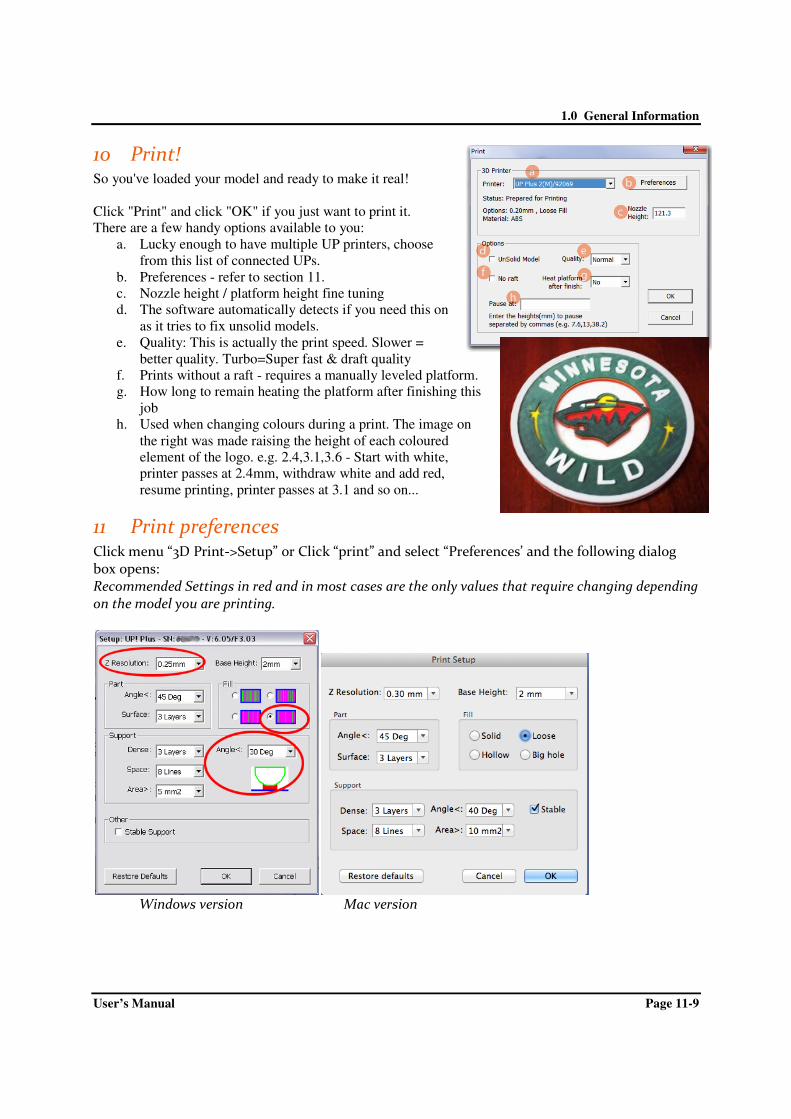
10 Print! So you've loaded your model and ready to make it real!
Click "Print" and click "OK" if you just want to print it.
There are a few handy options available to you:
a. Lucky enough to have multiple UP printers, choose
from this list of connected UPs.
b. Preferences - refer to section 11.
c. Nozzle height / platform height fine tuning
d. The software automatically detects if you need this on
as it tries to fix unsolid models.
e. Quality: This is actually the print speed. Slower =
better quality. Turbo=Super fast & draft quality
f. Prints without a raft - requires a manually leveled platform.
g. How long to remain heating the platform after finishing this
job
h. Used when changing colours during a print. The image on
the right was made raising the height of each coloured
element of the logo. e.g. 2.4,3.1,3.6 - Start with white,
printer passes at 2.4mm, withdraw white and add red,
resume printing, printer passes at 3.1 and so on...
11 Print preferences Click menu “3D Print->Setup” or Click “print” and select “Preferences’ and the following dialog box opens: Recommended Settings in red and in most cases are the only values that require changing depending on the model you are printing.
Windows version Mac version

1.0 General Information
User’s Manual Page 11-10
Z Resolution: Sets the print resolution (layer thickness) of the printer. This can be between 0.2mm per layer to 0.4mm per layer. The finer the layer thickness, the better quality, the stronger the printed part and the longer it takes to print.
Fill: There are four types of honeycomb fill that the interior of parts are made of. These cut away images below show the four different internal fill types.
Solid Honeycomb: The part is made of nearly solid plastic, which gives you the strongest part with a longer print time. This setting is recommended for strong and functional parts.
Semi-Solid Honeycomb
Semi-Hollow Honeycomb
Hollow Honeycomb: The Part is made mostly hollow, which gives you the weakest part but faster print time. Parts with flat top surfaces can slightly droop with this setting.
Support Options (Smart Support) The software’s Smart Support is where the software will automatically calculate where it requires support material. The Bunny on the left was printed with 80 degree support and then the support material is broken away to reveal the end result on the right. The recommended setting is 30 or 10 degrees. Support Angle: (Recommended Angle:30) Angle at which support material gets inserted. For example if 10° is used, support material only gets used if angle of surface is greater than 10° from horizontal (so support material is almost not used unless there is a direct overhang), If set to 50° than support material is used for any surface that is greater than 50° away from horizontal. In the image on the left of a green curve, the red indicates the amount of support material, changing the angle higher will produce more support.
Set to > 10° Set to > 50°

1.0 General Information
User’s Manual Page 11-11
There is always a delicate balance between minimizing the amount of support material, versus the quality of the part, versus the difficulty of removing support material. The orientation of the part on the print platform is also critical in determining both how much support material gets used, and also how difficult the support material will be to remove. As a general rule, it is easier to remove support material from the outside of a part than from the inside. As can be seen in the picture to the right, the part would use a lot more support material if printed with the opening facing downwards than if it were facing upwards.
Support - Dense: This represents how many layers of ‘solid’ (dense) material form part of the support structure directly beneath the model. Default = 3 layers Support - Space: The distance between the lines of non-solid support material. Changing this parameter requires some experience in balancing the quantity of support material used, ease of support material removal, and part print quality. Support - Area: The surface area above which support material gets used. When you choose 5mm2, for example, there will be no support if the overhanging area is less than 5mm2.
Base Height: This is the thickness of the raft of material before the support layer is printed under the part. When the printer starts printing, it first prints a raft of non-solid material in which all the lines of support material are horizontal (along the Y axis). It keeps building up horizontal rows of support material for as many mm as you have chosen. Then, just before it gets to the bottom surface of the real part, it starts to build support layers perpendicular to the raft layers layer. The default value is 2mm.

1.0 General Information
User’s Manual Page 11-12
Part - Angle: The part Angle determines at what point solid (dense) support material gets used. If the angle is small then the printer will add solid fill layers under the part surface. The thickness of this solid (dense) support is determined by the “dense” parameter under the Support options as described below. Part - Surface: This parameter determines how many layers form the bottom face of a part when it is not solid. For example, if you set it to 3, the machine will print 3 complete layers before going into non-solid mode. This does not, however, affect the side wall thickness on non-solid parts, which are all the same thickness (approximately 1.5mm) irrespective of the fill mode.
Stable Support: Stable support creates support that is more rigid and the model is less likely to distort, but the support material is more difficult to remove. Shell: By selecting this mode, the software will not create the internal honeycomb fill and will only create an external shell. For example printing the bunny with this selected will print a hollow bunny, saving material however making it fragile (2 layers thick). The shell option does not work well for parts with flat surface tops, e.g. a cube as there is nothing to support the top surface. Surface: With surface mode, it will print a model only 1 layer thick with no internal fill. It will also not create a flat bottom surface or the top flat surface. Printing the bunny in this mode will not create a bottom surface and its back will cave in. See the below comparison.

1.0 General Information
User’s Manual Page 12-13
12 Annotation of a 3d printed part
Shell is the outside shell of the part.
User selectable internal honeycomb fill of the
part. This gives the part strength.
Support material shelf. Example <30o
Support material concertina.
Surface is the 100% flat / horizontal bottom
or top of the part.
Raft is the foundation of the part.
Perfboard

1.0 General Information
User’s Manual Page 13-14
13 Removing finished printed parts When the model has finished printing, the printer will beep, and the
nozzle and platform stop heating. Open the door, using gloves, unlock
and remove the Perfboard out from the printer.
Either wait for the perfboard to cool down or use gloves if too hot.
Slide the spatula under the model and slowly wiggle it back and forth
to pry loose the model.
TIP: Remember to use gloves as the platform and model may still be
hot. The spatula is sharp, gloves must be worn.
The easiest way to remove support material is in this order:
Remove the raft from the model first
Next remove the concertina part of the support material
and lastly unclip the support shelf from the part.
13.1 Removing the raft
The first few layers that the printer lays down is referred to as the
Raft. In order to remove the raft from the model, if the base of the model is
flat. Its easiest using the spatula by sliding it between the raft and the model
and then sliding left and right in between the model. Pulling the raft off by
hand will normally cause ABS fatigue marks (were the ABS plastic goes
white from stress).
13.2 Removing Support Material
Printed models are composed of two parts. One part is the model itself, and
the other part is the support material used to support any overhanging parts of the
model.
The support material is the same physical material as the model material, but the
support material is printed at a lower density. It is very easy to distinguish the model from the support
material so it is easy to remove.
Have a look at the teapot in the pictures. The top picture shows the teapot
with its support material still attached and the right picture shows the teapot
with support material removed.
The support material gets removed using a combination of tools.
Some material can easily be cracked off by hand. Support material close to
the model is easier to remove using tools such as the knife and cutters.
TIPS: You can easily get
the original colour of the
ABS back by waving a
flame over the affected
area briefly.

1.0 General Information
User’s Manual Page 14-15
14 Maintenance
14.1 Caring for the Perfboard
The perfboard is a hard wearing platform and can be
used time and time again. You don't need to remove
the plastic from the inside holes, as when heated these
become sticky and help the model stuck down to the
platform to reduce warping. Once a print has completed, using the gloves
remove the perfboard and let it cool down. Then you can slightly flex the perfboard to attempt to release
the printed model. To clean the perfboard vigorously scrape the left over plastic off, on both sides to
prepare for the next print. If you find parts are no longer sticking, brush some acetone over the perfboard.
Spare or replacement perfboards are available to purchase.
14.2 Cleaning the Nozzle
It is recommended to replace your nozzle every 300 hours or 6 months. For most
people, it is easier to simply purchase replacement nozzles instead of the hassle of
cleaning old nozzles.
For best results obtain the "UP Essentials" tool kit.
What you need:
• Small blow torch
• 0.4mm drill bit (yes it is very small!)
• Acetone
• Safety gloves, glasses and mask.
• Long handled pliers
Pay attention to the safety instructions included with Acetone as
it is flammable.
• Do a withdraw and once the nozzle is over 240c, using the 0.4mm drill bit,
poke through the hole in the nozzle. Be careful not to break the drill bit inside the nozzle.
This alone offers a quick fix.
• Otherwise soak the nozzle in acetone for 1hr (overnight is better)
• and if all else fails then, wear a mask as the fumes from burning plastic
inside the nozzle are hazardous. Use the blow torch, hold the nozzle with the pliers and
burn the nozzle for around 4 minutes, to burnout the residue plastic.
• Cool the nozzle down in water
• Do another withdraw and screw the nozzle back on.
TIPS: Never attempt to
remove a printed model
whilst the perfboard is
loaded inside the printer.
Doing so will unlevel your
build platform.
STOP! Always check that the drive gear is clean, before attempting to clean the nozzle.
ALWAYS press "Withdraw" and whilst above 240c then unscrew the nozzle using the safety gloves. Failing to
follow this will damaged your extruder and void your extruder block warranty.
TIP: To keep your prints looking great it is important
to keep the outside of your nozzle clean and free
from leaving dark blotches in your prints. Always
keep your nozzle clean. Do a withdraw and once at
temperature (beep) give the nozzle a wipe with a
piece of old denim jeans (non synthetic).

1.0 General Information
User’s Manual Page 14-16
14.3 Cleaning the extruder column
The outside of the extruder block can be cleaned, when cold with a fine grain sandpaper.
The silver column that runs from the top through into the nozzle can get a buildup of burnt
particles on its inside walls. It is not a very common requirement to clean this part as in
order of importance cleaning 1) driver gear 2) nozzle 3) extruder column.
To clean the column:
• Remove the nozzle (follow the section Cleaning the Nozzle)
• Remove the print head from the printer
• Put a 1.5mm drill bit through the silver column
It is recommended to have a spare extruder block on hand.
14.4 Cleaning the drive gear
The drive gear tends to get a buildup of plastic dust over time as the gear grips into the filament and
pushes it down into the extruder block and time to time it slips. You can hear the slippage by a (click
click) sound coming from the print head, normally on the first layer of printing or when parts are warping.
The drive gear is the first place you want to check for problems.
What you need
An old toothbrush / a steel bristle brush is better
Small size Alan key
Safety gloves
• Withdraw the filament from the print head
• Wait around 20 minutes for the print head to cool down sufficiently before working on it
• On the top back of the print head, remove the rainbow ribbon cable cover.
• Unplug the rainbow ribbon cable from the print head.
• Unplug the black fan cable from the top of the print head
• Pull out the entire print head, held in place by magnets.
Either wait for the print head to cool or using
saftey gloves pull apart the black head cover from
the main body of the print head. The cover is held in
place by small snap lock dimples, so it might require
a bit of twisting and pulling action to release it.

1.0 General Information
User’s Manual Page 14-17
Using the Alan key tool, unscrew the white gear
cover (2 screws). Then pull the gear cover off the
motor (snap lock). Remove the plastic dust residue
from the gear and clean the surrounding area.
Be carefull when replacing the gear cover not over
tighten the two screws, otherwise you'll break the
gear cover.
Replace the print head in reverse order.
14.5 Lubrication
The linear rods on the UP 3D Printer may occasionally require a bit of lubrication to keep it operating
smoothly. The recommended to use lithium grease. When lubricating the bearings, first clean off as much
old grease as possible from the bearings, and then apply new grease to the bearing and slide each axis in
the appropriate direction to spread the grease.
14.6 Vertical calibration
If your models have a lean to them, like the leaning tower
of Pisa, only then you'll need to run the vertical calibration.
IMPORTANT: Ensure your platform is level, at the correct height and you have RESET the calibration values before starting this process!!! The Vertical calibration procedure allows you to ensure that the printer platform is perfectly horizontal and that the printer prints consistently in the X, Y and Z direction. 1. In the UP software, click “3D Print” menu and click “Calibrate” 2. Click “Reset” and click OK. (the status bar should then show 0 values as per picture) 3. In the UP software open the Calibration model located in “C:\program
files\UP\Example\Calibrate96.UP3” 4. Open the “Calibrate” box form the “3D Print” 5. 3D Print the calibration model. 6. After the calibration model is printed, measure the X1 and X2 length, as shown in the pictures
below.
Then enter the measured X1 and X2 values into the appropriate boxes.

1.0 General Information
User’s Manual Page 14-18
Remove the Front Centre ‘L’ shaped component, and measure its deviation. Put the exact value into the Z box. If it deviates to the right side, the value to be put into the Z box will be a positive value. If the deviates to the left, the value to put into the Z box will be a negative value. Finally, measure the height of Front Centre component, which should be 40mm. If the part measures near 40mm, enter 40mm as the value. Click “OK” to record all these values and exit the calibration window.

1.0 General Information
User’s Manual Page 15-19
15 Trouble shooting guide
15.1 Air printing
The term air printing comes from when the printer is performing the action of printing but nothing is
coming out of the nozzle. The biggest cause of air printing is NOT a blocked nozzle, but rather a buildup
of plastic dust around the drive gear.
Causes and Solutions
Filament diameter Always check the diameter of your filament using a vernier caliper and ensure the
filament is 1.75mm and within +/- 0.1. Too thin and the drive gear won't be able to
grip onto the filament. Too thick and the filament won't be able to fit inside the
silver column.
Parts warping A warping print lifts away from the perfboard and pushes up against the nozzle and
blocks the flow of plastic, thus causing the gear to slip on the filament. Creating dust
around the drive gear.
Platform to close to
the nozzle
If the nozzle is scraping on the platform it's too close and will cause the flow of
plastic to be blocked. You might hear a clicking sound from the gear slipping on the
filament.
Broken piece of
plastic in the silver
column
Open the head up and check for a broken piece, or a piece stuck in the entry of the
silver column
Carbon build up on
inside walls of
silver column
Refer to Maintenance section
Carbon build up
inside nozzle
Refer to Maintenance section
15.2 Increasing the nozzle height
If you find you can't increase the platform/nozzle height any further then do the following:
Load a model and do a print preview, then enter a greater value in the "Nozzle Height" box
and click OK. Now go into "Maintenance" and move the platform higher as required.
15.3 Warping & splitting parts
Warping is a constant battle of the forces of physics!
Warping of a model is a result of uneven thermal contraction
of the ABS during printing. Like most materials when heated
they expand and contract as cooled. If you printed a solid
cube the inside temperature would be greater than the outer
temperature and so the outside cools faster than the inside
and you end up with the part warping. So what if we print
the cube in a heated environment like the UP BOX. The
cube example would still be hotter on the inside than on the
outside, so the warping would still happen, just reduced. So
why don't we increase the environment temperature, this

1.0 General Information
User’s Manual Page 15-20
would reduce the effect of warping even more, but unfortunately this would also result in several other
problems. Even the large industrial plastic extrusion printers suffer from warping. To get around warping
it's about learning the best orientation to print a model, or splitting a model into parts.
Warping is caused by a number of different factors:
• The gap between the platform and the nozzle are not equal at all
points, i.e. the print platform is not level. e.g. Always warping from
one side.
• The nozzle height / distance between nozzle and platform is to great. If
the nozzle is too far away from the print platform, then the part will
not anchor correctly. As the part cools it will pull free of the perfboard,
resulting in warping. e.g. The raft warps away from the perfboard.
• The edge of the bed is cooler than the centre. A bead of ABS deposited at the same temp as it
exits the nozzle will cool more rapidly at the edge of the bed, the higher the temperature gradient,
the greater the contraction, so the plastic at the cooler edge will contract more and when this
occurs repeatedly (layer by layer) as a fresh layer retracts, it pulls the layer underneath up
slightly.
• Not sufficient pre-heating of the platform before printing. The larger the model, the more pre-
heating is required before starting a large print.
You absolutely must not open the UP BOX doors during printing, as it is as bad for the ABS as it would
be for opening the oven when making Soufflé. A sudden rush of cold air can warp or split your model.
Some materials shrink when cooled at a higher rate and unfortunately ABS is one of them. You should try
other materials like PLA as it doesn't warp as badly as ABS.
15.4 Blocked nozzle
When you perform an extrude, the filament should come out in a straight line. If it curls
around the nozzle or comes out at an angle refer the maintenance section. The photo to the
right shows a good extrusion.
15.5 Blocked extruder column
Check the maintenance section
15.6 Burn marks on the printed models
When printing with light coloured plastics like white, you will see brown burn marks. To reduce these
always keep your nozzle clean. Check the maintenance section
15.7 Nozzle too hot/cold error
The yellow cable connection that attaches to the extruder block is very fragile and can easily get damaged
from: cleaning the print head, wiggling the connection or a printed part crashing into the connection.
When the cable gets a small break in it, the software reports "Nozzle too hot / too cold" error". We
strongly suggest having a spare extruder block or print head available as a spare.

1.0 General Information
User’s Manual Page 16-21
16 How does the print head work
16.1 Extruder components
• Stepper Motor: Used to drive the plastic material into the
hot end.
• Drive Gear: Bites into the plastic and pushes it down with
some force into the hot end / extruder.
• Gear Cover: The bearing is to allow the filament to be
passed through easily.
• Heat sink & fan: This keeps the top part of the extruder
silver column cool, to ensure the filament remains solid
and rigid in order to push down onto the molten filament
below.
• Silver Column: Upper part of column dissipates heat
through the heatsink.
• Nozzle: Screwed into the Hot End / Extruder Block
• Extruder Block/Hot End: Heated up to 270c and
monitored by the temperature sensor.
16.2 Theory of plastic extrusion 3D Printing
1. The filament is pushed down by the drive gear, pushing the filament into the hot end.
2. Because the extruder gets very hot, the heat easily travels up the silver column and would soften the
filament. However we don't want that to happen.
3. The fan blows cold air onto the heat sink, so the heat sink deflects the heat from the upper part of the
silver column and the filament stays rigid.
4. The rigid filament pushes down on the molten filament and also creates a large back pressure on the
molten filament below, thus extruding it out of the tiny hole in the nozzle.
5. Without this pressure or force, you would not be able to print. You would be able to extrude as there is no
model or platform in the way when you do this. e.g. The model or platform slightly blocks the nozzle
during printing, thus a fair amount of force is required to extrude during printing and hence the filament is
squished out flat onto the model or platform.
The concept is like icing a cake, you need to put pressure on the bag to extrude out of a tiny hole.

User’s Manual
16.3 Extruder air flow
On the right hand side of the print head is an air flow adjustment knob.
With air flow blowing over the nozzle, this has the following effect:
• Increases print quality of unde
faster each layer. e.g. Rabbit chest is smoother
• Easier to remove the raft and support material from the model.
• Part strength on the Z axis is weaker as each layer is not melted into the
previous layer well.
• Increased warping or splitting of parts as the outside of the shape is
cooled too fast.
With the knob is the closed position, the opposite effect will occur.
• Decreased print quality of underside surfaces as the hot plastic droops over the edge of the
previous layer.
• Raft and support material is harder to remove from the model.
• Part strength on the Z axis is stronger as each layer is melted into the previous layer.
• Decreased warping or splitting of parts as the outside of the shape is not cooled.
17 Safety considerations
Warning Hot Surfaces!
these will be too hot to handle and could result in burns or personal injury. Always use the
included safety gloves when handling the head, nozzle, platform or
Warning! Turn off the printer before a) placing your hands
inside the printer b) before removing parts, cables or covers.
Ensure to tie back loose hair, loose clothing whilst the printer is in operation.
The Printer must be used in
otherwise the machine could become damaged or even cause a fire hazard. Keep the power
supply and printer
Failure to do so could re
It is recommended that you discharge any static charge from your body before touching the
machine to prevent an interruption while printing and any potential damage to the printer.
For best performance place an an
The printer is designed to work properly at an ambient temperature of between 15°C and
30°C and humidity of between 20% and 50%; Operating outside these limits may result in
decreased print qu
Extruder air flow
On the right hand side of the print head is an air flow adjustment knob.
With air flow blowing over the nozzle, this has the following effect:
Increases print quality of underside surfaces as the plastic is cooled
e.g. Rabbit chest is smoother
Easier to remove the raft and support material from the model.
Part strength on the Z axis is weaker as each layer is not melted into the
d warping or splitting of parts as the outside of the shape is
With the knob is the closed position, the opposite effect will occur.
Decreased print quality of underside surfaces as the hot plastic droops over the edge of the
Raft and support material is harder to remove from the model.
Part strength on the Z axis is stronger as each layer is melted into the previous layer.
Decreased warping or splitting of parts as the outside of the shape is not cooled.
tions
Warning Hot Surfaces! Never touch the print head, nozzle or print bed during operation,
these will be too hot to handle and could result in burns or personal injury. Always use the
included safety gloves when handling the head, nozzle, platform or
Turn off the printer before a) placing your hands
inside the printer b) before removing parts, cables or covers.
Ensure to tie back loose hair, loose clothing whilst the printer is in operation.
The Printer must be used in conjunction with the original manufacturer power supply,
otherwise the machine could become damaged or even cause a fire hazard. Keep the power
and printer away from moisture, water and out of high temperature environments.
Failure to do so could result in risk of electric shock of fire.
It is recommended that you discharge any static charge from your body before touching the
machine to prevent an interruption while printing and any potential damage to the printer.
For best performance place an anti static computer mat on the floor in front of the printer.
The printer is designed to work properly at an ambient temperature of between 15°C and
30°C and humidity of between 20% and 50%; Operating outside these limits may result in
decreased print quality of your models.
1.0 General Information
Page 17-22
Decreased print quality of underside surfaces as the hot plastic droops over the edge of the
Part strength on the Z axis is stronger as each layer is melted into the previous layer.
Decreased warping or splitting of parts as the outside of the shape is not cooled.
Never touch the print head, nozzle or print bed during operation,
these will be too hot to handle and could result in burns or personal injury. Always use the
printed parts.
Ensure to tie back loose hair, loose clothing whilst the printer is in operation.
conjunction with the original manufacturer power supply,
otherwise the machine could become damaged or even cause a fire hazard. Keep the power
and out of high temperature environments.
It is recommended that you discharge any static charge from your body before touching the
machine to prevent an interruption while printing and any potential damage to the printer.
ti static computer mat on the floor in front of the printer.
The printer is designed to work properly at an ambient temperature of between 15°C and
30°C and humidity of between 20% and 50%; Operating outside these limits may result in

1.0 General Information
User’s Manual Page 19-23
18 Appendix a - support Please take the time to join the UP community forum where are UP users hangout. forum.3dprintingsystems.com To get support for your product please contact 3D Printing Systems Australia New Zealand Phone: +61 (0)3 9099 0225 Phone: +64 (0)9 281 4206 [email protected] [email protected]
19 Appendix b – 3d related printing software There are many great free or low cost 3D CAD programs that can be used for design, scanning and cleaning up files to 3D print. For an every growing range of excellent software apps, check this list out: http://3dprintingsystems.com/education-stem-apps/ Library of 3D files ready to print.
• www.thingiverse.com
• www.grabcad.com

1.0 General Information
User’s Manual Page 19-24
Legal Notice The information in this document is subject to change without notice.
TIERTIME MAKES NO WARRANTY OF ANY KIND WITH REGARD TO THIS MATERIAL, INCLUDING, BUT NOT LIMITED TO, THE IMPLIED WARRANTIES OF MERCHANTABILITY AND FITNESS FOR A PARTICULAR PURPOSE. 3D Printing Systems Limited shall not be liable for errors contained herein or for incidental or consequential damages in connection with the furnishing, performance, or use of this Material. Changes or modifications to the system not expressly approved by Tiertime, the party responsible for compliance, could void the user’s authority for use. This document is protected by copyright. All rights reserved. Its use, disclosure, and possession are restricted by an agreement with Tiertime per software copyright. No part of this document may be photocopied, reproduced or translated into another language without the prior written consent of Tiertime. 3D Printing Systems are the exclusive distributors of the UP 3D Printers in Australia and New Zealand. © Copyright 2015 Tiertime & 3D Printing Systems Limited. All rights reserved.
Revision Sheet
Release No. Date Revision Description
Rev. 0 10/4/15 User’s Manual Created as draft
Rev. 1
Rev. 2