Embed Size (px)
Citation preview
OL-8550-07
C H A P T E R 16
Configuring MSTPThis chapter describes how to configure the Cisco implementation of the IEEE 802.1s Multiple STP (MSTP) on the Catalyst 2960 switch.
Note The multiple spanning-tree (MST) implementation in Cisco IOS Release 12.2(25)SED is based on the IEEE 802.1s standard. The MST implementations in earlier Cisco IOS releases are prestandard.
The MSTP enables multiple VLANs to be mapped to the same spanning-tree instance, reducing the number of spanning-tree instances needed to support a large number of VLANs. The MSTP provides for multiple forwarding paths for data traffic and enables load balancing. It improves the fault tolerance of the network because a failure in one instance (forwarding path) does not affect other instances (forwarding paths). The most common initial deployment of MSTP is in the backbone and distribution layers of a Layer 2 switched network. This deployment provides the highly available network required in a service-provider environment.
When the switch is in the MST mode, the Rapid Spanning Tree Protocol (RSTP), which is based on IEEE 802.1w, is automatically enabled. The RSTP provides rapid convergence of the spanning tree through explicit handshaking that eliminates the IEEE 802.1D forwarding delay and quickly transitions root ports and designated ports to the forwarding state.
Both MSTP and RSTP improve the spanning-tree operation and maintain backward compatibility with equipment that is based on the (original) IEEE 802.1D spanning tree, with existing Cisco-proprietary Multiple Instance STP (MISTP), and with existing Cisco per-VLAN spanning-tree plus (PVST+) and rapid per-VLAN spanning-tree plus (rapid PVST+). For information about PVST+ and rapid PVST+, see Chapter 15, “Configuring STP.” For information about other spanning-tree features such as Port Fast, UplinkFast, root guard, and so forth, see Chapter 17, “Configuring Optional Spanning-Tree Features.”
For complete syntax and usage information for the commands used in this chapter, see the command reference for this release.
This chapter consists of these sections:
• Understanding MSTP, page 16-2
• Understanding RSTP, page 16-8
• Configuring MSTP Features, page 16-13
Displaying the MST Configuration and Status, page 16-26
16-1Catalyst 3750 Switch Software Configuration Guide
Chapter 16 Configuring MSTPUnderstanding MSTP
Understanding MSTP
•
•
• Hop Count, page 16-5
• Boundary Ports, page 16-6
• IEEE 802.1s Implementation, page 16-6
• Interoperability with IEEE 802.1D STP, page 16-8
For configuration information, see the “Configuring MSTP Features” section on page 16-13.
Multiple Spanning-Tree Regions
Figure 16-1 on page 16-4.
The MST configuration controls to which MST region each switch belongs. The configuration includes the name of the region, the revision number, and the MST VLAN-to-instance assignment map. You configure the switch for a region by using the spanning-tree mst configuration
instancename revision
IST, CIST, and CST
•
16-2Catalyst 3750 Switch Software Configuration Guide
OL-8550-07
An MST instance is local to the region; for example, MST instance 1 in region A is independent of MST instance 1 in region B, even if regions A and B are interconnected.
A common and internal spanning tree (CIST), which is a collection of the ISTs in each MST region, and the common spanning tree (CST) that interconnects the MST regions and single spanning trees.
The spanning tree computed in a region appears as a subtree in the CST that encompasses the entire switched domain. The CIST is formed by the spanning-tree algorithm running among switches that support the IEEE 802.1w, IEEE 802.1s, and IEEE 802.1D standards. The CIST inside an MST region is the same as the CST outside a region.
For more information, see the “Operations Within an MST Region” section on page 16-3 and the “Operations Between MST Regions” section on page 16-3.
The implementation of the IEEE 802.1s standard, changes some of the terminology associated with MST implementations. For a summary of these changes, see Table 15-1 on page 15-4.
Operations Within an MST Region
IST master
When an MSTP switch initializes, it sends BPDUs claiming itself as the root of the CIST and the CIST regional root, with both of the path costs to the CIST root and to the CIST regional root set to zero. The switch also initializes all of its MST instances and claims to be the root for all of them. If the switch receives superior MST root information (lower switch ID, lower path cost, and so forth) than currently stored for the port, it relinquishes its claim as the CIST regional root.
During initialization, a region might have many subregions, each with its own CIST regional root. As switches receive superior IST information, they leave their old subregions and join the new subregion that contains the true CIST regional root. Thus all subregions shrink, except for the one that contains the true CIST regional root.
For correct operation, all switches in the MST region must agree on the same CIST regional root. Therefore, any two switches in the region only synchronize their port roles for an MST instance if they converge to a common CIST regional root.
Operations Between MST Regions
16-3
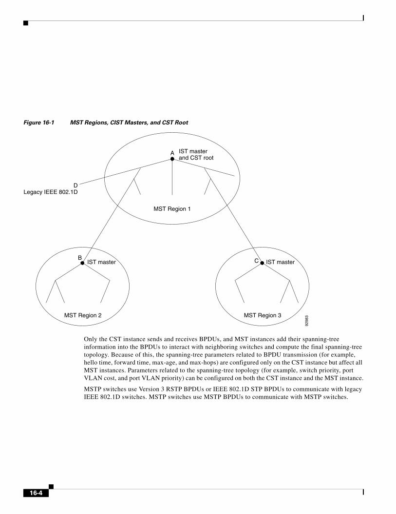
Figure 16-1 MST Regions, CIST Masters, and CST Root
Only the CST instance sends and receives BPDUs, and MST instances add their spanning-tree information into the BPDUs to interact with neighboring switches and compute the final spanning-tree topology. Because of this, the spanning-tree parameters related to BPDU transmission (for example, hello time, forward time, max-age, and max-hops) are configured only on the CST instance but affect all MST instances. Parameters related to the spanning-tree topology (for example, switch priority, port VLAN cost, and port VLAN priority) can be configured on both the CST instance and the MST instance.
MSTP switches use Version 3 RSTP BPDUs or IEEE 802.1D STP BPDUs to communicate with legacy IEEE 802.1D switches. MSTP switches use MSTP BPDUs to communicate with MSTP switches.
IST masterand CST root
IST master IST master
A
MST Region 1
DLegacy IEEE 802.1D
B
MST Region 2 MST Region 3
C
9298
3
16-4
IEEE 802.1s Terminology
Some MST naming conventions used in Cisco’s prestandard implementation have been changed to identify some internal regional
Hop Count
spanning-tree mst max-hops
Table 16-1 Prestandard and Standard Terminology
IEEE Standard Cisco Prestandard Cisco Standard
16-5
Chapter 16 Configuring MSTPUnderstanding MSTP
Boundary Ports
There is no definition of a boundary port in the IEEE 802.1s standard. The IEEE 802.1Q-2002 standard identifies two kinds of messages that a port can receive: internal (coming from the same region) and external. When a message is external, it is received only by the CIST. If the CIST role is root or alternate, or if the external BPDU is a topology change, it could have an impact on the MST instances. When a message is internal, the CIST part is received by the CIST, and each MST instance receives its respective M-record. The Cisco prestandard implementation treats a port that receives an external message as a boundary port. This means a port cannot receive a mix of internal and external messages.
An MST region includes both switches and LANs. A segment belongs to the region of its designated port. Therefore, a port in a different region than the designated port for a segment is a boundary port. This definition allows two ports internal to a region to share a segment with a port belonging to a different region, creating the possibility of receiving both internal and external messages on a port.
The primary change from the Cisco prestandard implementation is that a designated port is not defined as boundary, unless it is running in an STP-compatible mode.
Note If there is a legacy STP switch on the segment, messages are always considered external.
The other change from the prestandard implementation is that the CIST regional root switch ID field is now inserted where an RSTP or legacy IEEE 802.1Q switch has the sender switch ID. The whole region performs like a single virtual switch by sending a consistent sender switch ID to neighboring switches. In this example, switch C would receive a BPDU with the same consistent sender switch ID of root, whether or not A or B is designated for the segment.
IEEE 802.1s Implementation
Port Role Naming Change
• The boundary port is the root port of the CIST regional root—When the CIST instance port is proposed and is in sync, it can send back an agreement and move to the forwarding state only after all the corresponding MSTI ports are in sync (and thus forwarding). The MSTI ports now have a special role.
Catalyst 3750 Switch Software Configuration GuideOL-8550-07
showtype
Interoperation Between Legacy and Standard Switches
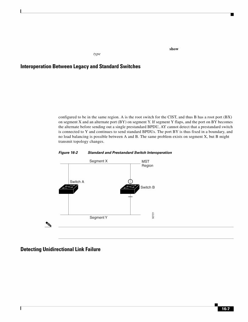
configured to be in the same region. A is the root switch for the CIST, and thus B has a root port (BX) on segment X and an alternate port (BY) on segment Y. If segment Y flaps, and the port on BY becomes the alternate before sending out a single prestandard BPDU, AY cannot detect that a prestandard switch is connected to Y and continues to send standard BPDUs. The port BY is thus fixed in a boundary, and no load balancing is possible between A and B. The same problem exists on segment X, but B might transmit topology changes.
Figure 16-2 Standard and Prestandard Switch Interoperation
Detecting Unidirectional Link Failure
Segment X MSTRegion
Segment Y 9272
1
Switch A
Switch B
16-7
Chapter 16 Configuring MSTPUnderstanding RSTP
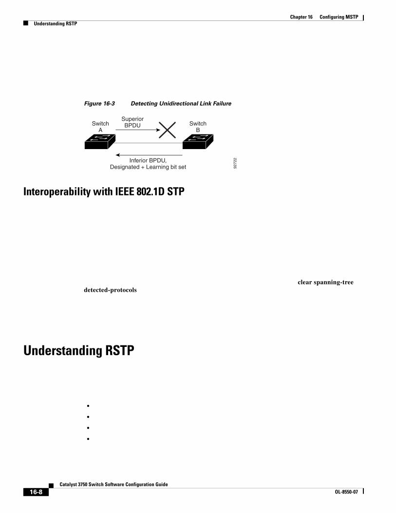
Figure 16-3 Detecting Unidirectional Link Failure
Interoperability with IEEE 802.1D STP
clear spanning-tree detected-protocols
Understanding RSTP
•
•
•
•
Inferior BPDU,Designated + Learning bit set
SuperiorBPDUSwitch
ASwitch
B
9272
2
16-8Catalyst 3750 Switch Software Configuration Guide
OL-8550-07
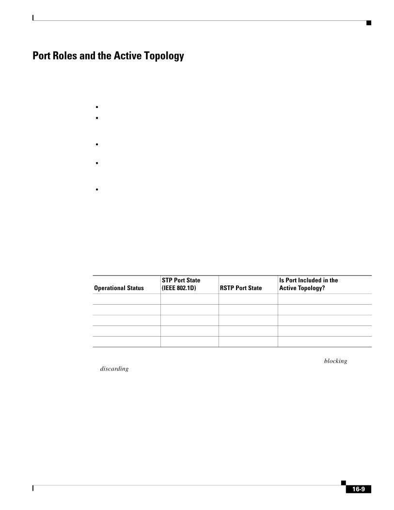
Port Roles and the Active Topology
•
•
•
•
•
blockingdiscarding
Operational StatusSTP Port State (IEEE 802.1D) RSTP Port State
Is Port Included in the Active Topology?
16-9
Chapter 16 Configuring MSTPUnderstanding RSTP
•
•
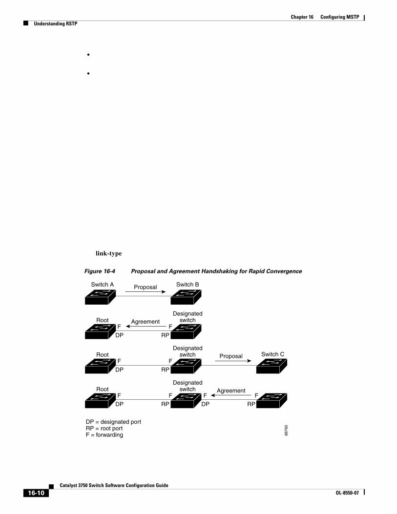
link-type
Figure 16-4 Proposal and Agreement Handshaking for Rapid Convergence
ProposalSwitch A Switch B
FF
RPDP
FF
RPDP
FF
RPDP
FF
RPDP
Switch C
8876
0
AgreementRootDesignated
switch
RootDesignated
switch Proposal
RootDesignated
switch Agreement
DP = designated portRP = root portF = forwarding
16-10Catalyst 3750 Switch Software Configuration Guide
OL-8550-07
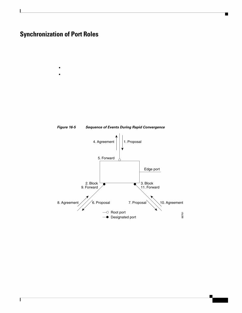
Synchronization of Port Roles
•
•
Figure 16-5 Sequence of Events During Rapid Convergence
2. Block9. Forward
1. Proposal4. Agreement
6. Proposal
Root portDesignated port
8. Agreement 10. Agreement
Edge port
7. Proposal
5. Forward
3. Block11. Forward
8876
1
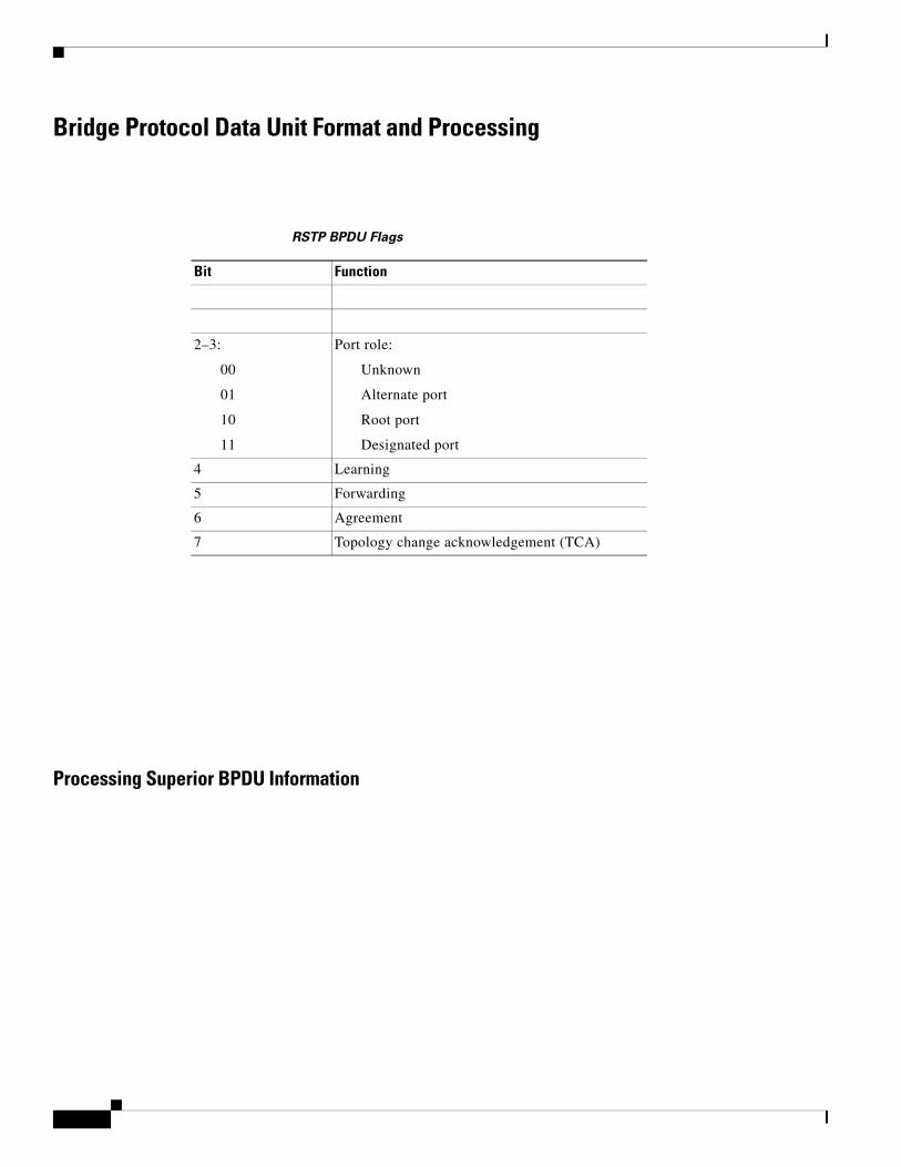
Bridge Protocol Data Unit Format and Processing
Processing Superior BPDU Information
RSTP BPDU Flags
Bit Function
2–3:
00
01
10
11
Port role:
Unknown
Alternate port
Root port
Designated port
4 Learning
5 Forwarding
6 Agreement
7 Topology change acknowledgement (TCA)
Chapter 16 Configuring MSTPConfiguring MSTP Features
Processing Inferior BPDU Information
Topology Changes
•
•
•
•
•
Configuring MSTP Features
•
• MSTP Configuration Guidelines, page 16-14
• Specifying the MST Region Configuration and Enabling MSTP, page 16-15 (required)
• Configuring the Root Switch, page 16-17 (optional)
Catalyst 3750 Switch Software Configuration GuideOL-8550-07
Chapter 16 Configuring MSTPConfiguring MSTP Features
• Configuring a Secondary Root Switch, page 16-18 (optional)
• Configuring Port Priority, page 16-19 (optional)
• Configuring Path Cost, page 16-20 (optional)
• Configuring the Switch Priority, page 16-21 (optional)
• Configuring the Hello Time, page 16-22 (optional)
• Configuring the Forwarding-Delay Time, page 16-23 (optional)
• Configuring the Maximum-Aging Time, page 16-23 (optional)
• Configuring the Maximum-Hop Count, page 16-24 (optional)
• Specifying the Link Type to Ensure Rapid Transitions, page 16-24 (optional)
• Designating the Neighbor Type, page 16-25 (optional)
• Restarting the Protocol Migration Process, page 16-25 (optional)
Default MSTP ConfigurationTable 16-4 shows the default MSTP configuration.
For information about the supported number of spanning-tree instances, see the “Supported Spanning-Tree Instances” section on page 15-9.
MSTP Configuration Guidelines
•
•
Feature Default Setting
Catalyst 3750 Switch Software Configuration GuideOL-8550-07
Chapter 16 Configuring MSTPConfiguring MSTP Features
•
•
•
•
•
•
•
Specifying the MST Region Configuration and Enabling MSTP
Command Purpose
Step 1
Step 2
Catalyst 3750 Switch Software Configuration GuideOL-8550-07
Chapter 16 Configuring MSTPConfiguring MSTP Features
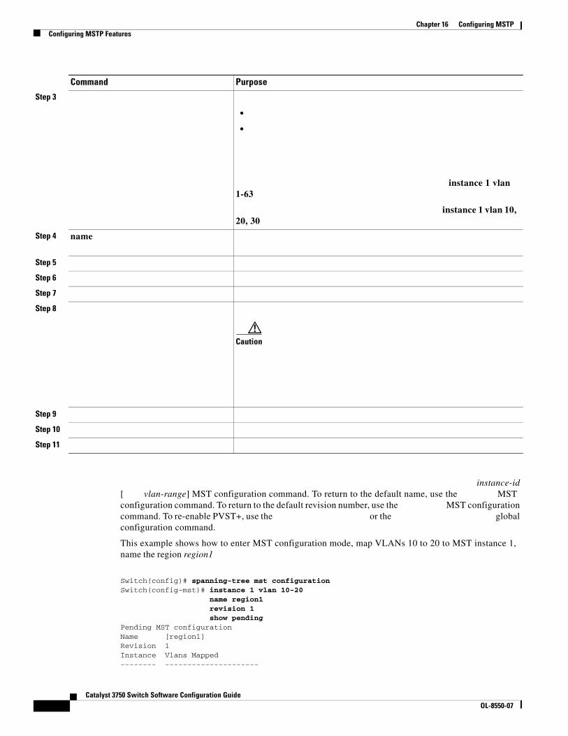
instance-id[ vlan-range] MST configuration command. To return to the default name, use the MST configuration command. To return to the default revision number, use the MST configuration command. To re-enable PVST+, use the or the global configuration command.
This example shows how to enter MST configuration mode, map VLANs 10 to 20 to MST instance 1, name the region region1
Switch(config)# spanning-tree mst configurationSwitch(config-mst)# instance 1 vlan 10-20
name region1revision 1show pending
Pending MST configurationName [region1]Revision 1Instance Vlans Mapped-------- ---------------------
Step 3
•
•
instance 1 vlan 1-63
instance 1 vlan 10, 20, 30
Step 4 name
Step 5
Step 6
Step 7
Step 8
Caution
Step 9
Step 10
Step 11
Command Purpose
Catalyst 3750 Switch Software Configuration GuideOL-8550-07
Chapter 16 Configuring MSTPConfiguring MSTP Features
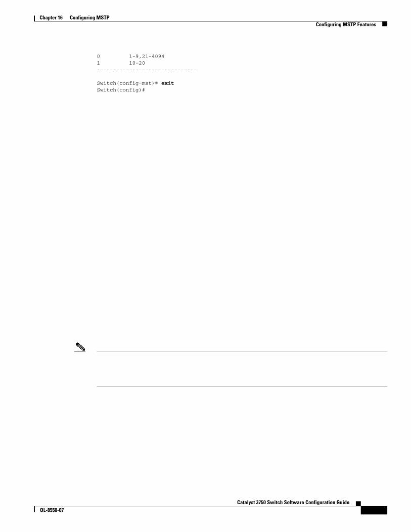
0 1-9,21-40941 10-20-------------------------------
Switch(config-mst)# exitSwitch(config)#
Catalyst 3750 Switch Software Configuration GuideOL-8550-07

interface-id
interface-id
instance-id
instance-id priority
instance-id
priority
interface-id
instance-id
interface-id
interface-id
instance-id
instance-id instance-id
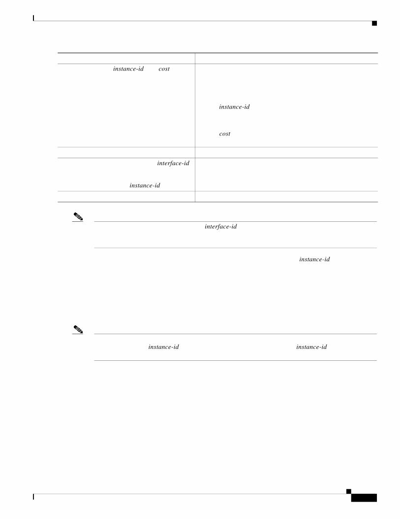
instance-id cost
instance-id
cost
interface-id
instance-id
instance-id
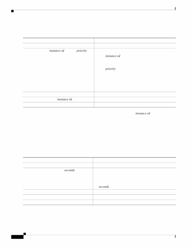
instance-id priority
instance-id
priority
instance-id
seconds
seconds
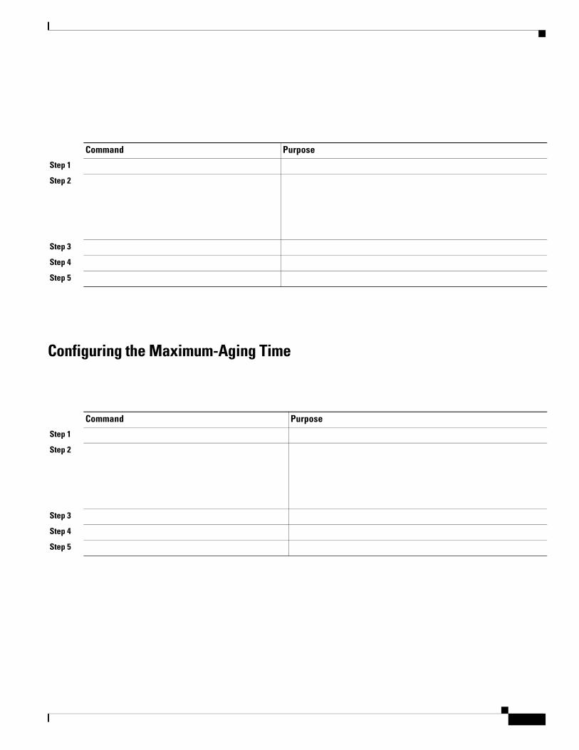
Configuring the Maximum-Aging Time
Command Purpose
Step 1
Step 2
Step 3
Step 4
Step 5
Command Purpose
Step 1
Step 2
Step 3
Step 4
Step 5
Chapter 16 Configuring MSTPConfiguring MSTP Features
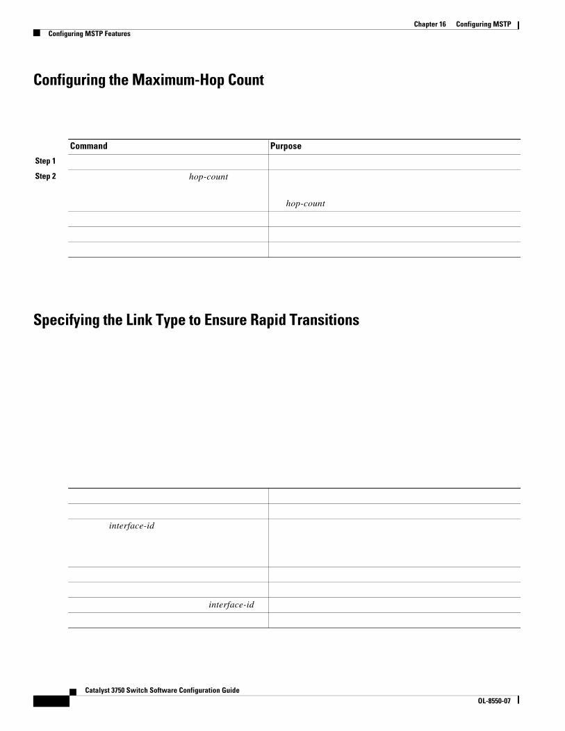
Configuring the Maximum-Hop Count
Specifying the Link Type to Ensure Rapid Transitions
Command Purpose
Step 1
Step 2 hop-count
hop-count
interface-id
interface-id
Catalyst 3750 Switch Software Configuration GuideOL-8550-07
Designating the Neighbor Type
Restarting the Protocol Migration Process
Command Purpose
Step 1
Step 2
Step 3
Step 4
Step 5
Step 6
Chapter 16 Configuring MSTPDisplaying the MST Configuration and Status
Displaying the MST Configuration and Status
Command Purpose
Catalyst 3750 Switch Software Configuration GuideOL-8550-07