Embed Size (px)
Citation preview
Configuration — VLANs and SpanningTreeAvaya Virtual Services Platform 9000
3.1NN46250-500, 02.02
June 2011
© 2011 Avaya Inc.
All Rights Reserved.
Notice
While reasonable efforts have been made to ensure that theinformation in this document is complete and accurate at the time ofprinting, Avaya assumes no liability for any errors. Avaya reserves theright to make changes and corrections to the information in thisdocument without the obligation to notify any person or organization ofsuch changes.
Documentation disclaimer
“Documentation” means information published by Avaya in varyingmediums which may include product information, operating instructionsand performance specifications that Avaya generally makes availableto users of its products. Documentation does not include marketingmaterials. Avaya shall not be responsible for any modifications,additions, or deletions to the original published version ofdocumentation unless such modifications, additions, or deletions wereperformed by Avaya. End User agrees to indemnify and hold harmlessAvaya, Avaya's agents, servants and employees against all claims,lawsuits, demands and judgments arising out of, or in connection with,subsequent modifications, additions or deletions to this documentation,to the extent made by End User.
Link disclaimer
Avaya is not responsible for the contents or reliability of any linked Websites referenced within this site or documentation provided by Avaya.Avaya is not responsible for the accuracy of any information, statementor content provided on these sites and does not necessarily endorsethe products, services, or information described or offered within them.Avaya does not guarantee that these links will work all the time and hasno control over the availability of the linked pages.
Warranty
Avaya provides a limited warranty on its Hardware and Software(“Product(s)”). Refer to your sales agreement to establish the terms ofthe limited warranty. In addition, Avaya’s standard warranty language,as well as information regarding support for this Product while underwarranty is available to Avaya customers and other parties through theAvaya Support Web site: http://support.avaya.com. Please note that ifyou acquired the Product(s) from an authorized Avaya reseller outsideof the United States and Canada, the warranty is provided to you bysaid Avaya reseller and not by Avaya.
Licenses
THE SOFTWARE LICENSE TERMS AVAILABLE ON THE AVAYAWEBSITE, HTTP://SUPPORT.AVAYA.COM/LICENSEINFO/ AREAPPLICABLE TO ANYONE WHO DOWNLOADS, USES AND/ORINSTALLS AVAYA SOFTWARE, PURCHASED FROM AVAYA INC.,ANY AVAYA AFFILIATE, OR AN AUTHORIZED AVAYA RESELLER(AS APPLICABLE) UNDER A COMMERCIAL AGREEMENT WITHAVAYA OR AN AUTHORIZED AVAYA RESELLER. UNLESSOTHERWISE AGREED TO BY AVAYA IN WRITING, AVAYA DOESNOT EXTEND THIS LICENSE IF THE SOFTWARE WAS OBTAINEDFROM ANYONE OTHER THAN AVAYA, AN AVAYA AFFILIATE OR ANAVAYA AUTHORIZED RESELLER; AVAYA RESERVES THE RIGHTTO TAKE LEGAL ACTION AGAINST YOU AND ANYONE ELSEUSING OR SELLING THE SOFTWARE WITHOUT A LICENSE. BYINSTALLING, DOWNLOADING OR USING THE SOFTWARE, ORAUTHORIZING OTHERS TO DO SO, YOU, ON BEHALF OFYOURSELF AND THE ENTITY FOR WHOM YOU ARE INSTALLING,DOWNLOADING OR USING THE SOFTWARE (HEREINAFTERREFERRED TO INTERCHANGEABLY AS “YOU” AND “END USER”),AGREE TO THESE TERMS AND CONDITIONS AND CREATE ABINDING CONTRACT BETWEEN YOU AND AVAYA INC. OR THEAPPLICABLE AVAYA AFFILIATE ( “AVAYA”).
Copyright
Except where expressly stated otherwise, no use should be made ofmaterials on this site, the Documentation, Software, or Hardwareprovided by Avaya. All content on this site, the documentation and theProduct provided by Avaya including the selection, arrangement anddesign of the content is owned either by Avaya or its licensors and isprotected by copyright and other intellectual property laws including thesui generis rights relating to the protection of databases. You may notmodify, copy, reproduce, republish, upload, post, transmit or distributein any way any content, in whole or in part, including any code andsoftware unless expressly authorized by Avaya. Unauthorizedreproduction, transmission, dissemination, storage, and or use withoutthe express written consent of Avaya can be a criminal, as well as acivil offense under the applicable law.
Third-party components
Certain software programs or portions thereof included in the Productmay contain software distributed under third party agreements (“ThirdParty Components”), which may contain terms that expand or limitrights to use certain portions of the Product (“Third Party Terms”).Information regarding distributed Linux OS source code (for thoseProducts that have distributed the Linux OS source code), andidentifying the copyright holders of the Third Party Components and theThird Party Terms that apply to them is available on the Avaya SupportWeb site: http://support.avaya.com/Copyright.
Trademarks
The trademarks, logos and service marks (“Marks”) displayed in thissite, the Documentation and Product(s) provided by Avaya are theregistered or unregistered Marks of Avaya, its affiliates, or other thirdparties. Users are not permitted to use such Marks without prior writtenconsent from Avaya or such third party which may own the Mark.Nothing contained in this site, the Documentation and Product(s)should be construed as granting, by implication, estoppel, or otherwise,any license or right in and to the Marks without the express writtenpermission of Avaya or the applicable third party.
Avaya is a registered trademark of Avaya Inc.
All non-Avaya trademarks are the property of their respective owners,and “Linux” is a registered trademark of Linus Torvalds.
Downloading Documentation
For the most current versions of Documentation, see the AvayaSupport Web site: http://support.avaya.com.
Contact Avaya Support
Avaya provides a telephone number for you to use to report problemsor to ask questions about your Product. The support telephone numberis 1-800-242-2121 in the United States. For additional supporttelephone numbers, see the Avaya Web site: http://support.avaya.com.
2 Configuration — VLANs and Spanning Tree June 2011Comments? [email protected]
Contents
Chapter 1: New in this release........................................................................................... 7Features.................................................................................................................................................... 7Other changes........................................................................................................................................... 7
Chapter 2: Introduction...................................................................................................... 9Chapter 3: VLAN fundamentals......................................................................................... 11
Port-based VLANs.................................................................................................................................... 12Policy-based VLANs................................................................................................................................. 13VLAN tagging and port types.................................................................................................................... 20VLAN router interfaces.............................................................................................................................. 22IP routing and VLANs................................................................................................................................ 22VLAN implementation............................................................................................................................... 23VLAN configuration rules.......................................................................................................................... 24VLAN feature support................................................................................................................................ 24Microsoft NLB clustering systems............................................................................................................. 25VLAN MAC-layer filtering database and MAC security............................................................................. 28Prevention of IP spoofing within a VLAN.................................................................................................. 29VLAN loop detection................................................................................................................................. 30
Chapter 4: Spanning tree fundamentals........................................................................... 33Rapid Spanning Tree Protocol and Multiple Spanning Tree Protocol....................................................... 34
Chapter 5: VLAN configuration using Enterprise Device Manager................................ 39Configuring the VLAN feature on a port.................................................................................................... 40Viewing existing VLANs............................................................................................................................ 42Viewing ports in a null VLAN..................................................................................................................... 42Creating a port-based VLAN..................................................................................................................... 43Configuring an IP address for a VLAN...................................................................................................... 46Changing VLAN port membership............................................................................................................ 47Creating a source IP subnet-based VLAN................................................................................................ 48Creating a protocol-based VLAN.............................................................................................................. 49Configuring user-defined protocol-based VLANs...................................................................................... 50Configuring a source MAC address-based VLAN..................................................................................... 52Configuring source MAC addresses for a source MAC-based VLAN....................................................... 53Configuring advanced VLAN features....................................................................................................... 54Configuring NLB support........................................................................................................................... 57Configuring a port to accept tagged or untagged frames.......................................................................... 58Configuring untagging default VLAN on a tagged port............................................................................. 59Configuring VLAN loop detection.............................................................................................................. 59Configuring directed broadcast on a VLAN............................................................................................... 60Configuring the forwarding database timeout........................................................................................... 61Viewing VLAN forwarding database information....................................................................................... 62Viewing the forwarding database for a specific VLAN.............................................................................. 63Clearing learned MAC addresses by VLAN.............................................................................................. 64Clearing learned MAC addresses for all VLANs by port........................................................................... 65Configuring static forwarding..................................................................................................................... 65Configuring static multicast for a bridge.................................................................................................... 66
Configuration — VLANs and Spanning Tree June 2011 3
Enabling global MAC security................................................................................................................... 67Configuring multiple DSAPs and SSAPs.................................................................................................. 68Enabling unknown MAC discard............................................................................................................... 69Configuring MAC learning parameters...................................................................................................... 69Configuring MAC address learning........................................................................................................... 71Modifying auto-learned MAC addresses................................................................................................... 72Configuring limit learning........................................................................................................................... 73
Chapter 6: VLAN configuration using ACLI...................................................................... 75Creating a VLAN....................................................................................................................................... 76Assigning an IP address to a VLAN.......................................................................................................... 78Performing a general VLAN action........................................................................................................... 79Configuring static MAC addresses for a VLAN......................................................................................... 80Enabling global MAC security................................................................................................................... 81Limiting MAC address learning................................................................................................................. 82Configuring autolearning and allowed MAC addresses............................................................................ 83Adding or removing ports in a VLAN......................................................................................................... 85Adding or removing source MAC addresses for a VLAN.......................................................................... 86Configuring VLAN classification precedence............................................................................................ 87Configuring NLB support........................................................................................................................... 88Configuring a tagged port to discard untagged frames............................................................................. 89Configuring VLAN loop detection.............................................................................................................. 90Configuring spoof detection...................................................................................................................... 91Configuring multiple DSAP and SSAP...................................................................................................... 92Viewing VLAN information........................................................................................................................ 93Viewing brouter port information............................................................................................................... 94Viewing VLAN port member status........................................................................................................... 94Viewing VLAN source MAC addresses..................................................................................................... 95Viewing VLAN forwarding database information....................................................................................... 96Viewing manual edit MAC addresses....................................................................................................... 97Viewing multicast MAC addresses............................................................................................................ 97Viewing NLB-mode information................................................................................................................. 98Viewing port-level MAC security............................................................................................................... 98
Chapter 7: Spanning Tree configuration using Enterprise Device Manager................. 101Restarting the Avaya Virtual Services Platform 9000............................................................................... 101Configuring RSTP global parameters....................................................................................................... 102Configuring RSTP ports............................................................................................................................ 104Viewing RSTP port status......................................................................................................................... 106Configuring the Spanning Tree mode....................................................................................................... 107Configuring MSTP global parameters....................................................................................................... 108Configuring CIST ports for MSTP............................................................................................................. 111Configuring MSTI bridges for MSTP......................................................................................................... 114Configuring MSTI ports for MSTP............................................................................................................. 116
Chapter 8: Spanning Tree configuration using ACLI....................................................... 119Configuring Spanning Tree....................................................................................................................... 120Configuring Rapid Spanning Tree Protocol............................................................................................... 120Configuring Rapid Spanning Tree Protocol for a port............................................................................... 122Configuring the Rapid Spanning Tree Protocol version............................................................................ 123
4 Configuration — VLANs and Spanning Tree June 2011
Viewing the global RSTP configuration information.................................................................................. 124Viewing RSTP statistics............................................................................................................................ 124Viewing the RSTP status.......................................................................................................................... 124Viewing the RSTP configuration information............................................................................................. 125Viewing the RSTP status for a port........................................................................................................... 125Viewing RSTP information for a selected port.......................................................................................... 126Viewing the RSTP role.............................................................................................................................. 127Viewing spanning tree configuration......................................................................................................... 127Configuring Multiple Spanning Tree Protocol............................................................................................ 128Configuring MSTP MSTI options............................................................................................................... 129Configuring Ethernet MSTP...................................................................................................................... 130Configuring Ethernet MSTP MSTI............................................................................................................. 131Viewing MSTP configurations................................................................................................................... 132Viewing MSTP status................................................................................................................................ 132Viewing MSTP port information................................................................................................................. 133Viewing MSTP MSTI information.............................................................................................................. 133Viewing MSTP statistics............................................................................................................................ 134
Chapter 9: Customer service............................................................................................. 135Getting technical documentation............................................................................................................... 135Getting product training............................................................................................................................. 135Getting help from a distributor or reseller.................................................................................................. 135Getting technical support from the Avaya Web site.................................................................................. 136
Index..................................................................................................................................... 137
Configuration — VLANs and Spanning Tree June 2011 5

6 Configuration — VLANs and Spanning Tree June 2011
Chapter 1: New in this release
The following sections detail what’s new in Avaya Virtual Services Platform 9000 Configuration — VLANsand Spanning Tree (NN46250–500) for Release 3.1:
• Features on page 7
• Other changes on page 7
FeaturesSee the following section for information about feature-related changes.
Microsoft NLBIn Release 3.1, you can use Microsoft Network Load Balancer (NLB) to share the workloadamong multiple clustering servers. The Virtual Services Platform 9000 interoperates withMicrosoft NLB clusters operating in the following modes:
• Unicast mode• Multicast mode• IGMP multicast mode
For interoperability with Microsoft NLB, the Virtual Services Platform 9000 providesconfiguration options at the global and at the VLAN level. For more information, see thefollowing sections:
• Microsoft NLB clustering systems on page 25• Configuring NLB support on page 57• Configuring NLB support on page 88• Viewing NLB-mode information on page 98
Other changesSee the following sections for information about changes that are not feature-related.
Variable definitionsVariable definitions and field descriptions are moved to follow the steps in a procedure.
Configuration — VLANs and Spanning Tree June 2011 7
Chapter 2: Introduction
This document contains procedural and conceptual information to help you configure and manage virtuallocal area networks (VLAN), Rapid Spanning Tree Protocol (RSTP), and Multiple Spanning Tree Protocol(MSTP) on the Avaya Virtual Services Platform 9000. This document provides instructions for using theAvaya Command Line Interface (ACLI) and the Enterprise Device Manager (EDM).
For more information about the terms and acronyms used in this document, see Avaya Virtual ServicesPlatform 9000 Terminology, NN46250-101.
• VLAN fundamentals on page 11• Spanning tree fundamentals on page 33• VLAN configuration using Enterprise Device Manager on page 39• VLAN configuration using ACLI on page 75• Spanning Tree configuration using Enterprise Device Manager on page 101• Spanning Tree configuration using ACLI on page 119
Configuration — VLANs and Spanning Tree June 2011 9
Chapter 3: VLAN fundamentals
This section describes the virtual local area network (VLAN) features supported on the Avaya VirtualServices Platform 9000.
For more information about the user interface, see Avaya Virtual Services Platform 9000 User InterfaceFundamentals, NN46250-103.
A VLAN is a switched network that is logically segmented by functions, project teams, or applicationswithout regard to the physical location of users. By using a VLAN, you can divide the Local Area Networkinto smaller groups without interfering with the physical network.
The practical applications of VLAN include the following:
• You can create VLANs, or workgroups, for common interest groups.• You can create VLANs, or workgroups, for specific types of network traffic.• You can add, move, or delete members from these workgroups without making physical changes to
the network.By dividing the network into separate VLANs, you can create separate broadcast domains. Thisarrangement conserves bandwidth, especially in networks supporting broadcast and multicastapplications that flood the network with traffic. A VLAN workgroup can include members from a numberof dispersed physical segments on the network, improving traffic flow between them.
The Virtual Services Platform 9000 performs the Layer 2 switching functions necessary to transmitinformation within VLANs, as well as the Layer 3 routing functions necessary for VLANs to communicatewith one another. You can define a VLAN for a single switch or spanning multiple switches. A port can bea member of multiple VLANs. A VLAN is associated with a spanning tree group.
A VLAN packet is classified before it is forwarded. If the packet matches a classification rule, the portmembership is checked. If the port is not an allowed member (potential, static, or active), the system dropsthe packet.
• Port-based VLANs on page 12• Policy-based VLANs on page 13• VLAN tagging and port types on page 20• VLAN router interfaces on page 22• IP routing and VLANs on page 22• VLAN implementation on page 23• VLAN configuration rules on page 24• VLAN feature support on page 24• Microsoft NLB clustering systems on page 25
Configuration — VLANs and Spanning Tree June 2011 11
• Prevention of IP spoofing within a VLAN on page 29• VLAN loop detection on page 30
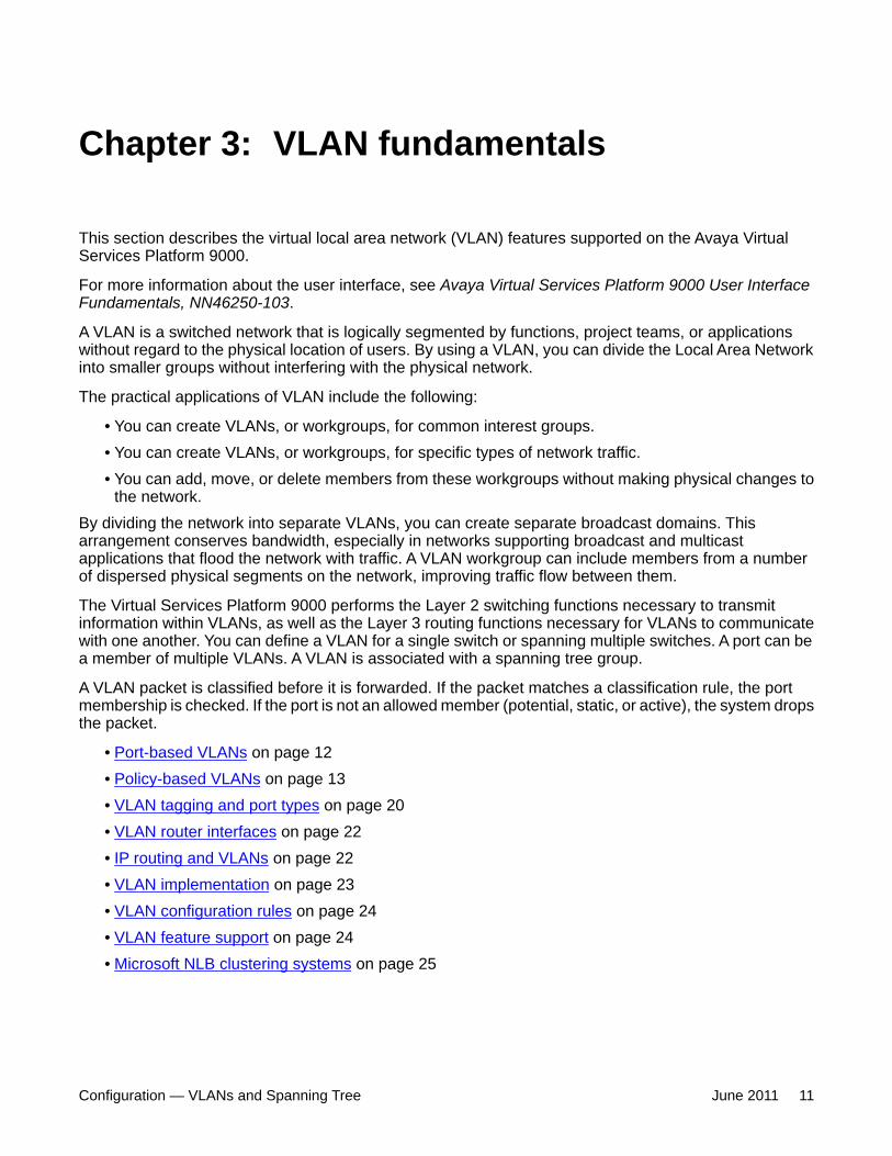
Port-based VLANsA port-based VLAN is a VLAN in which you explicitly configure the ports to be in the VLAN.When you create a port-based VLAN on a device, you assign a VLAN identification number(VLAN ID) and specify the ports that belong to the VLAN. These port members are alwaysactive port members. The VLAN ID is used to coordinate VLANs across multiple switches. Anytype of frame may be classified to a port-based VLAN.
The example in the following figure shows two port-based VLANs: one for the marketingdepartment, and one for the sales department. Ports are assigned to each port-based VLAN.A change in the sales area can move the sales representative at port 3/1 (the first port in theinput/output [I/O] module in chassis slot 3) to the marketing department without moving cables.With a port-based VLAN, you only need to indicate in the Avaya Command Line Interface(ACLI) that port 3/1 in the sales VLAN now is a member of the marketing VLAN.
Figure 1: Port-based VLAN
VLAN fundamentals
12 Configuration — VLANs and Spanning Tree June 2011Comments? [email protected]
Policy-based VLANsReceived frames are classified into a policy-based VLAN based on certain fields of the framethat matches the associated VLAN policy. You can base a policy on protocol, IP subnet, orsource MAC address.
• Port membership types on page 13• Protocol-based VLANs on page 14• Example of a PPPoE protocol-based VLAN on page 16• User-defined protocol-based VLANs on page 17• Source MAC address-based VLANs on page 18• IP subnet-based VLANs on page 19
Port membership typesIn a policy-based VLAN, a port can be designated as a potential member, a static member, orone not allowed to be a member of the VLAN.
If a port is designated as a potential member of the VLAN, and the incoming traffic matchesthe policy, the system dynamically adds the port to the active port list of the VLAN, making theport an active member of the VLAN. After the system adds a port to the active list, it can removethe port from the active list due to time-out. Potential member ports that join the VLAN areremoved (timed out) from the active port list of the VLAN after the timeout (aging time) periodof that VLAN expires.
All members of the Spanning Tree Group associated with a protocol-based or IP subnet-basedVLAN are automatically considered potential members of the VLAN. In addition, all taggedports (trunk ports) become static ports. If you do not want all the tagged ports to be staticmembers of a protocol-based VLAN or a subnet-based VLAN, put the port in the disallowedlist. The only exception to this is source-MAC address-based VLANs. For source-MAC-basedVLANs, no ports are added as potential port members. The VLANs behave like port-basedVLANs and you must add the port members.
Static port members are always members of the VLAN. Static port members are not aged outdue to inactivity and they are not removed from the active list. If a server or router connects toa port, designate that port as a static member of a VLAN. If a server connects to a port that isonly a potential member and the server sends very little traffic, a client fails to reach the serverif the server port is timed out of the VLAN. Avaya recommends that you make these ports staticmembers of the VLAN.
A disallowed port can never become a member of the VLAN until you add it as a port-member.After you remove a port from the VLAN, the system adds the port to the disallowed list.
On any single spanning-tree instance, an access (untagged) port can belong to one port-basedVLAN and many policy-based VLANs. A trunk (tagged) port can belong to many port-basedand policy-based VLANs.
The following table describes port membership types for policy-based VLANs.
Policy-based VLANs
Configuration — VLANs and Spanning Tree June 2011 13
Table 1: Port membership types for policy-based VLANs
Membership type DescriptionPotential Potential members of a VLAN become active members upon
receiving data matching the policy defined for the VLAN (apacket tagged with that VLAN, or an untagged packet matchingthe policy).
Static(always a member)
Static members are always active members of the VLAN afteryou configure them as belonging to that VLAN.
Not allowed to join(never a member)
Ports of this type cannot join the VLAN.
The following table lists supported policy-based VLANs.
Table 2: Supported policy-based VLAN types
VLAN type Virtual Services Platform 9000Protocol-based supported
Source-MAC address-based supported
IP subnet-based supported
Protocol-based VLANsProtocol-based VLANs are an effective way to segment your network into broadcast domainsaccording to the network protocols in use. Traffic generated by network protocol—Appletalk,Point-to-Point Protocol over Ethernet (PPPoE)—can be automatically confined to its ownVLAN.
A port member of a port-based VLAN can belong to multiple protocol-based VLANs. Porttagging is not required for a port to be a member of multiple protocol-based VLANs.
The Virtual Services Platform 9000 supports the following protocol-based VLANs:
• IP version 4 (IP)• AppleTalk on Ethernet Type 2 and Ethernet SNAP frames (AppleTalk)• Digital Equipment Corporation Local Area Transport (DEC LAT) Protocol (decLat)• Other DEC protocols (decOther)• International Business Machines Systems Network Architecture (IBM SNA) on IEEE
802.2 frames (sna802dot2)• IBM SNA on Ethernet Type 2 frames (snaEthernet2)• NetBIOS Protocol (netBIOS)• Xerox Network Systems (XNS)• Banyan VINES (vines)• Reverse Address Resolution Protocol (RARP)
VLAN fundamentals
14 Configuration — VLANs and Spanning Tree June 2011Comments? [email protected]
• Point-to-Point Protocol over Ethernet (PPPoE)• ipv6• ipx802dot2• ipx802dot3• ipxEthernet2• ipxSnap• user-defined protocols
Multiple protocol-based VLANs cannot be defined for the same protocol.
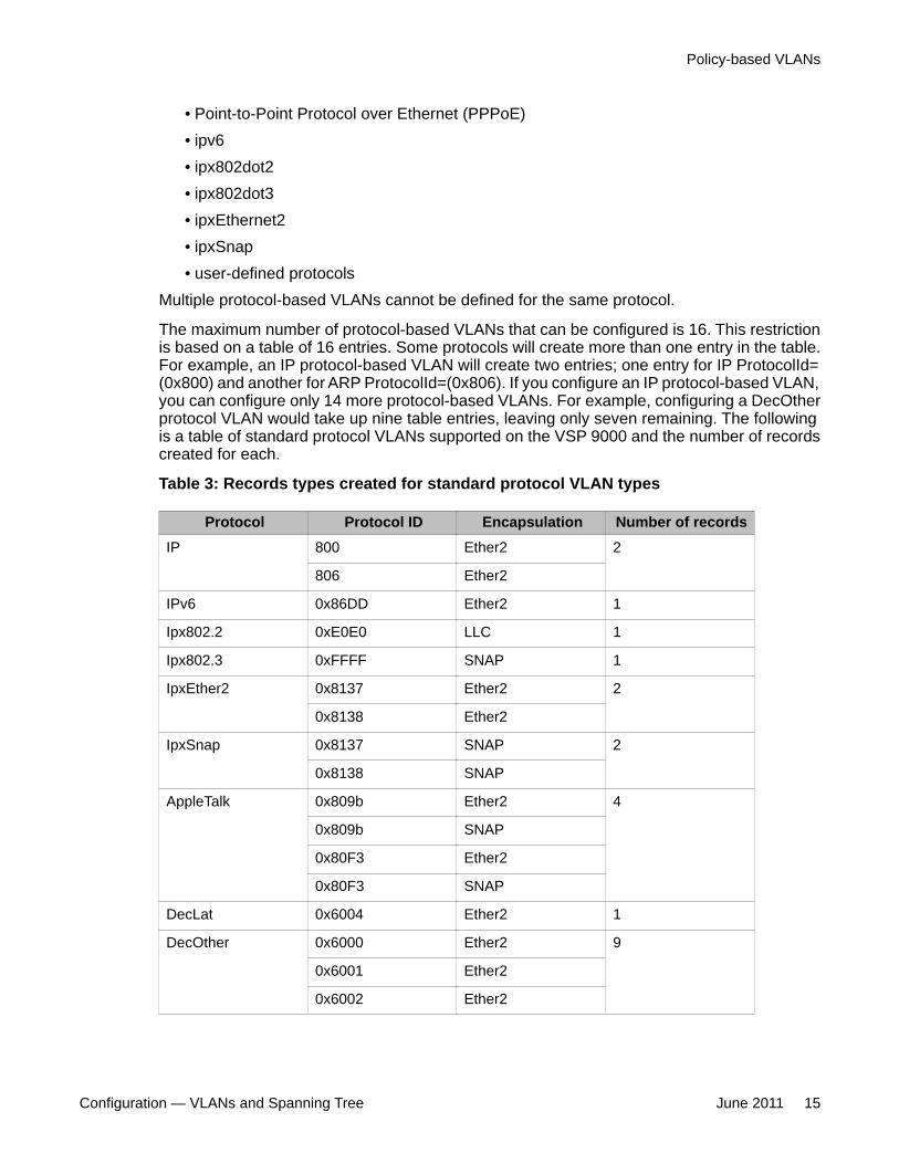
The maximum number of protocol-based VLANs that can be configured is 16. This restrictionis based on a table of 16 entries. Some protocols will create more than one entry in the table.For example, an IP protocol-based VLAN will create two entries; one entry for IP ProtocolId=(0x800) and another for ARP ProtocolId=(0x806). If you configure an IP protocol-based VLAN,you can configure only 14 more protocol-based VLANs. For example, configuring a DecOtherprotocol VLAN would take up nine table entries, leaving only seven remaining. The followingis a table of standard protocol VLANs supported on the VSP 9000 and the number of recordscreated for each.
Table 3: Records types created for standard protocol VLAN types
Protocol Protocol ID Encapsulation Number of recordsIP 800 Ether2 2
806 Ether2
IPv6 0x86DD Ether2 1
Ipx802.2 0xE0E0 LLC 1
Ipx802.3 0xFFFF SNAP 1
IpxEther2 0x8137 Ether2 2
0x8138 Ether2
IpxSnap 0x8137 SNAP 2
0x8138 SNAP
AppleTalk 0x809b Ether2 4
0x809b SNAP
0x80F3 Ether2
0x80F3 SNAP
DecLat 0x6004 Ether2 1
DecOther 0x6000 Ether2 9
0x6001 Ether2
0x6002 Ether2
Policy-based VLANs
Configuration — VLANs and Spanning Tree June 2011 15
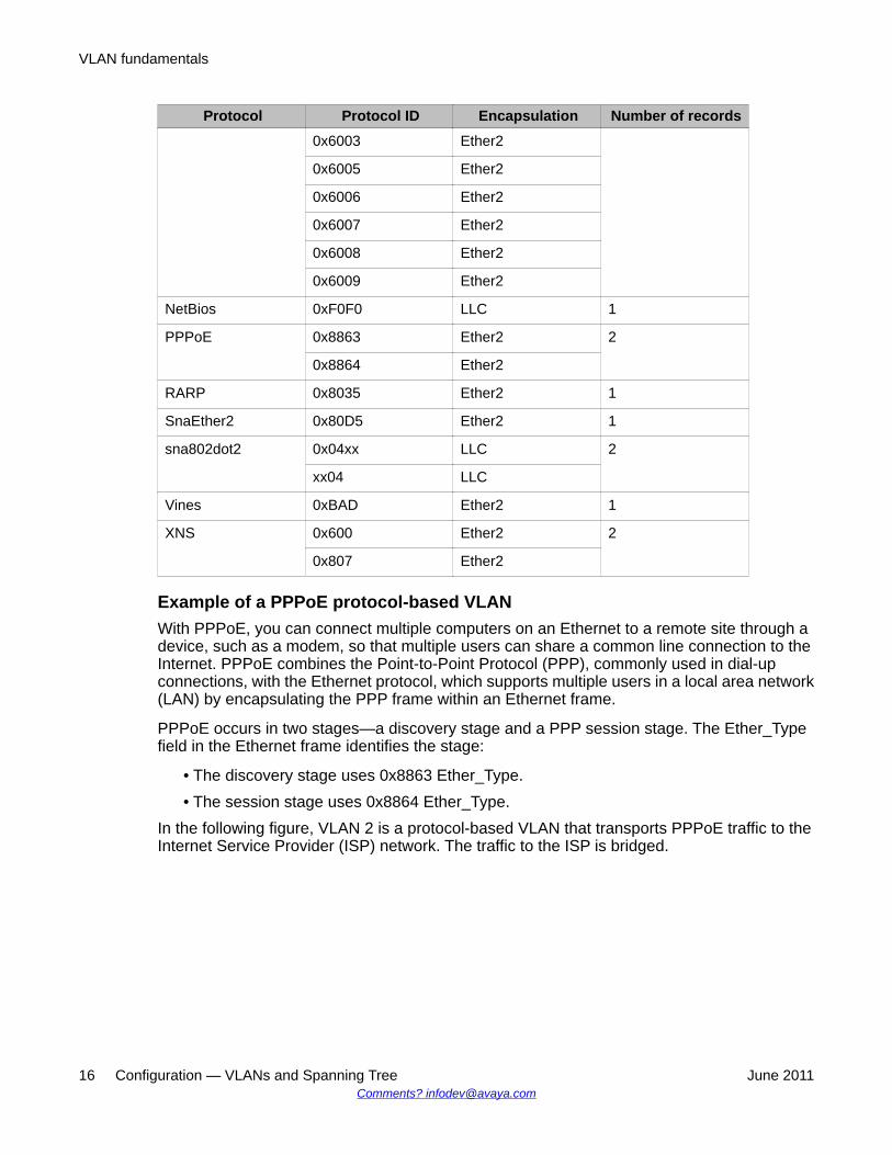
Protocol Protocol ID Encapsulation Number of records0x6003 Ether2
0x6005 Ether2
0x6006 Ether2
0x6007 Ether2
0x6008 Ether2
0x6009 Ether2
NetBios 0xF0F0 LLC 1
PPPoE 0x8863 Ether2 2
0x8864 Ether2
RARP 0x8035 Ether2 1
SnaEther2 0x80D5 Ether2 1
sna802dot2 0x04xx LLC 2
xx04 LLC
Vines 0xBAD Ether2 1
XNS 0x600 Ether2 2
0x807 Ether2
Example of a PPPoE protocol-based VLANWith PPPoE, you can connect multiple computers on an Ethernet to a remote site through adevice, such as a modem, so that multiple users can share a common line connection to theInternet. PPPoE combines the Point-to-Point Protocol (PPP), commonly used in dial-upconnections, with the Ethernet protocol, which supports multiple users in a local area network(LAN) by encapsulating the PPP frame within an Ethernet frame.
PPPoE occurs in two stages—a discovery stage and a PPP session stage. The Ether_Typefield in the Ethernet frame identifies the stage:
• The discovery stage uses 0x8863 Ether_Type.• The session stage uses 0x8864 Ether_Type.
In the following figure, VLAN 2 is a protocol-based VLAN that transports PPPoE traffic to theInternet Service Provider (ISP) network. The traffic to the ISP is bridged.
VLAN fundamentals
16 Configuration — VLANs and Spanning Tree June 2011Comments? [email protected]
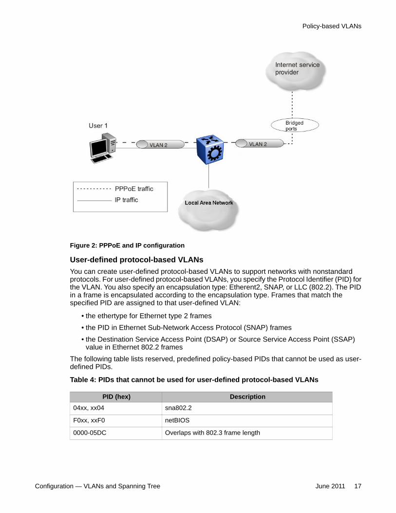
Figure 2: PPPoE and IP configuration
User-defined protocol-based VLANsYou can create user-defined protocol-based VLANs to support networks with nonstandardprotocols. For user-defined protocol-based VLANs, you specify the Protocol Identifier (PID) forthe VLAN. You also specify an encapsulation type: Etherent2, SNAP, or LLC (802.2). The PIDin a frame is encapsulated according to the encapsulation type. Frames that match thespecified PID are assigned to that user-defined VLAN:
• the ethertype for Ethernet type 2 frames• the PID in Ethernet Sub-Network Access Protocol (SNAP) frames• the Destination Service Access Point (DSAP) or Source Service Access Point (SSAP)
value in Ethernet 802.2 framesThe following table lists reserved, predefined policy-based PIDs that cannot be used as user-defined PIDs.
Table 4: PIDs that cannot be used for user-defined protocol-based VLANs
PID (hex) Description04xx, xx04 sna802.2
F0xx, xxF0 netBIOS
0000-05DC Overlaps with 802.3 frame length
Policy-based VLANs
Configuration — VLANs and Spanning Tree June 2011 17
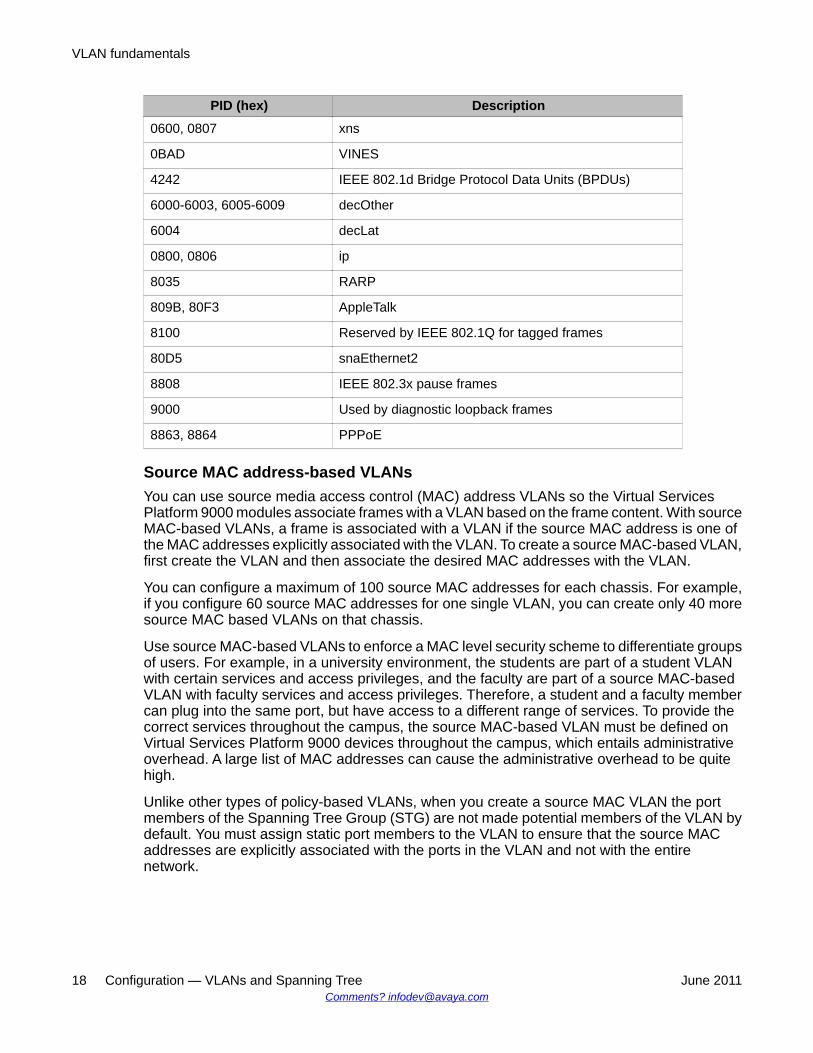
PID (hex) Description0600, 0807 xns
0BAD VINES
4242 IEEE 802.1d Bridge Protocol Data Units (BPDUs)
6000-6003, 6005-6009 decOther
6004 decLat
0800, 0806 ip
8035 RARP
809B, 80F3 AppleTalk
8100 Reserved by IEEE 802.1Q for tagged frames
80D5 snaEthernet2
8808 IEEE 802.3x pause frames
9000 Used by diagnostic loopback frames
8863, 8864 PPPoE
Source MAC address-based VLANsYou can use source media access control (MAC) address VLANs so the Virtual ServicesPlatform 9000 modules associate frames with a VLAN based on the frame content. With sourceMAC-based VLANs, a frame is associated with a VLAN if the source MAC address is one ofthe MAC addresses explicitly associated with the VLAN. To create a source MAC-based VLAN,first create the VLAN and then associate the desired MAC addresses with the VLAN.
You can configure a maximum of 100 source MAC addresses for each chassis. For example,if you configure 60 source MAC addresses for one single VLAN, you can create only 40 moresource MAC based VLANs on that chassis.
Use source MAC-based VLANs to enforce a MAC level security scheme to differentiate groupsof users. For example, in a university environment, the students are part of a student VLANwith certain services and access privileges, and the faculty are part of a source MAC-basedVLAN with faculty services and access privileges. Therefore, a student and a faculty membercan plug into the same port, but have access to a different range of services. To provide thecorrect services throughout the campus, the source MAC-based VLAN must be defined onVirtual Services Platform 9000 devices throughout the campus, which entails administrativeoverhead. A large list of MAC addresses can cause the administrative overhead to be quitehigh.
Unlike other types of policy-based VLANs, when you create a source MAC VLAN the portmembers of the Spanning Tree Group (STG) are not made potential members of the VLAN bydefault. You must assign static port members to the VLAN to ensure that the source MACaddresses are explicitly associated with the ports in the VLAN and not with the entirenetwork.
VLAN fundamentals
18 Configuration — VLANs and Spanning Tree June 2011Comments? [email protected]
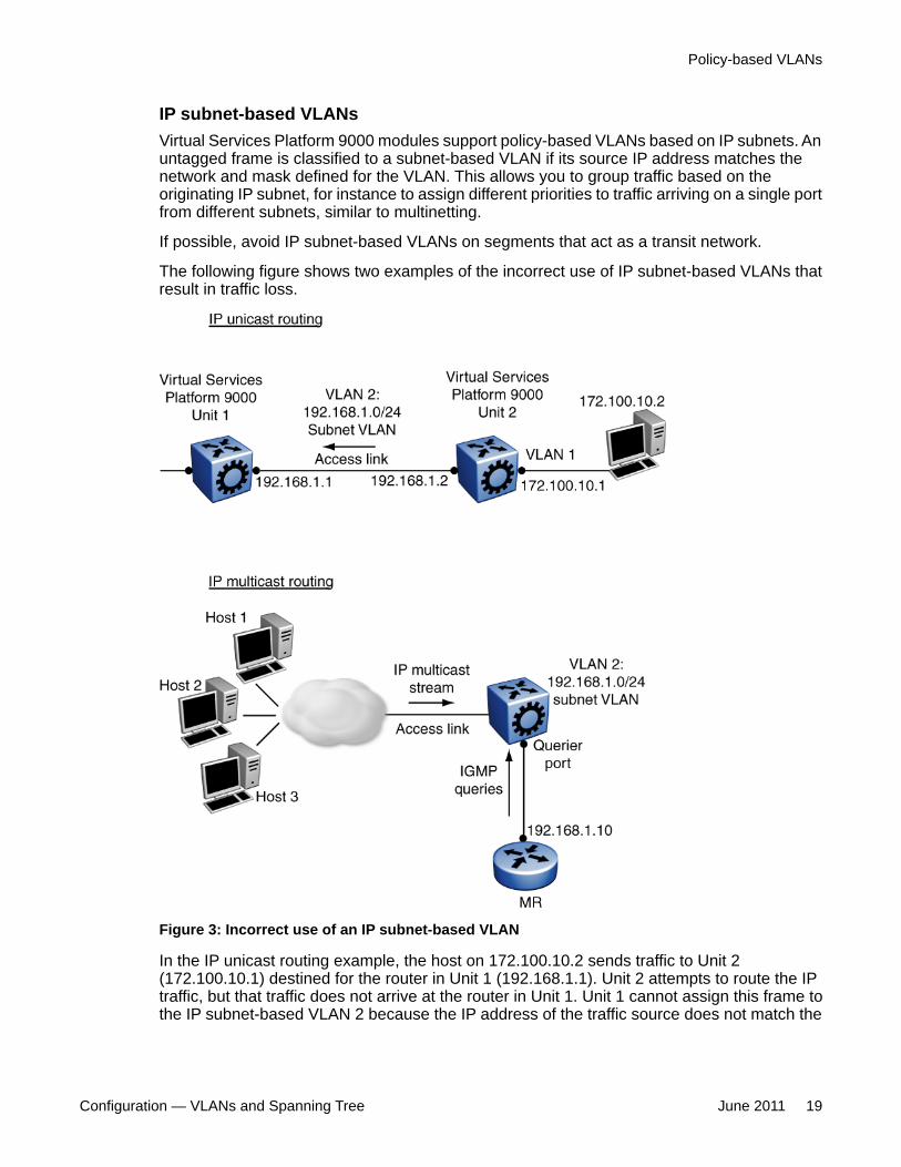
IP subnet-based VLANsVirtual Services Platform 9000 modules support policy-based VLANs based on IP subnets. Anuntagged frame is classified to a subnet-based VLAN if its source IP address matches thenetwork and mask defined for the VLAN. This allows you to group traffic based on theoriginating IP subnet, for instance to assign different priorities to traffic arriving on a single portfrom different subnets, similar to multinetting.
If possible, avoid IP subnet-based VLANs on segments that act as a transit network.
The following figure shows two examples of the incorrect use of IP subnet-based VLANs thatresult in traffic loss.
Figure 3: Incorrect use of an IP subnet-based VLAN
In the IP unicast routing example, the host on 172.100.10.2 sends traffic to Unit 2(172.100.10.1) destined for the router in Unit 1 (192.168.1.1). Unit 2 attempts to route the IPtraffic, but that traffic does not arrive at the router in Unit 1. Unit 1 cannot assign this frame tothe IP subnet-based VLAN 2 because the IP address of the traffic source does not match the
Policy-based VLANs
Configuration — VLANs and Spanning Tree June 2011 19
IP subnet assigned to VLAN 2. If the access link in VLAN 2 that connects Units 1 and 2 werea tagged link, the traffic would be associated with the VLAN tag, not the IP address, and wouldbe forwarded correctly to Unit 1.
In the IP multicast routing example, the multicast stream is on an access link that is part of theIP subnet-based VLAN 2. If the source IP address in the multicast data packets received onthe access port is not within the subnet of VLAN 2 (a likely scenario), the multicast streamcannot reach the multicast router (MR).
VLAN tagging and port typesThe Virtual Services Platform 9000 supports the IEEE 802.1Q specification for tagging framesand coordinating VLANs across multiple switches.
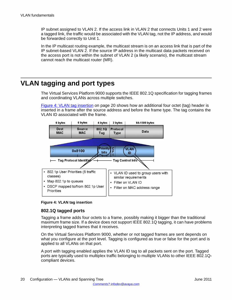
Figure 4: VLAN tag insertion on page 20 shows how an additional four octet (tag) header isinserted in a frame after the source address and before the frame type. The tag contains theVLAN ID associated with the frame.
Figure 4: VLAN tag insertion
802.1Q tagged portsTagging a frame adds four octets to a frame, possibly making it bigger than the traditionalmaximum frame size. If a device does not support IEEE 802.1Q tagging, it can have problemsinterpreting tagged frames that it receives.
On the Virtual Services Platform 9000, whether or not tagged frames are sent depends onwhat you configure at the port level. Tagging is configured as true or false for the port and isapplied to all VLANs on that port.
A port with tagging enabled applies the VLAN ID tag to all packets sent on the port. Taggedports are typically used to multiplex traffic belonging to multiple VLANs to other IEEE 802.1Q-compliant devices.
VLAN fundamentals
20 Configuration — VLANs and Spanning Tree June 2011Comments? [email protected]
If you disable tagging on a port, it does not send tagged frames. A nontagged port connects aVirtual Services Platform 9000 to devices that do not support IEEE 802.1Q tagging. If a taggedframe is forwarded to a port with tagging configured to false, the Virtual Services Platform 9000removes the tag from the frame before sending it to the port.
Treatment of tagged and untagged framesThe Virtual Services Platform 9000 associates a frame with a VLAN based on the data contentof the frame and the configuration of the receiving port. The treatment of the frame dependson whether the frame is tagged or untagged.
If a tagged frame is received on a port, if the port is a static or potential member of the VLANID specified in the tag, the Virtual Services Platform 9000 directs it to that VLAN. If the port isnot a member of the VLAN that is identified by the tag in the packet, the Virtual ServicesPlatform discards the packet. If a port is untagged, you can configure it to discard taggedframes received on the port. In this case the tagged frame is discarded.
For untagged frames, VLAN membership is implied from the content of the frame itself. Youcan configure a tagged port to accept or discard untagged frames received on the port.
A port’s default VLAN is the VLAN to which untagged frames will be classified if they don’tmatch the criteria of any policy-based VLAN of which the port is a member. The port’s defaultVLAN can be any port-based VLAN a port belongs to, or the unassigned VLAN (0). Framesclassified to the unassigned VLAN will be discarded.
The frame is forwarded based on the VLAN on which the frame is received, and on theforwarding options available for that VLAN. The Virtual Services Platform 9000 tries toassociate untagged frames with a VLAN in the following order:
• Does the frame belong to a source MAC-based VLAN?• Does the frame belong to an IP subnet-based VLAN?• Does the frame belong to a protocol-based VLAN?• What is the default VLAN for the receiving port?• Is the default VLAN for the port not the unassigned VLAN?
If the frame meets none of these criteria, it is discarded.
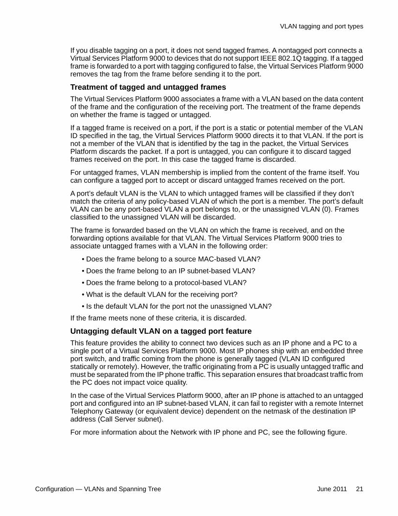
Untagging default VLAN on a tagged port featureThis feature provides the ability to connect two devices such as an IP phone and a PC to asingle port of a Virtual Services Platform 9000. Most IP phones ship with an embedded threeport switch, and traffic coming from the phone is generally tagged (VLAN ID configuredstatically or remotely). However, the traffic originating from a PC is usually untagged traffic andmust be separated from the IP phone traffic. This separation ensures that broadcast traffic fromthe PC does not impact voice quality.
In the case of the Virtual Services Platform 9000, after an IP phone is attached to an untaggedport and configured into an IP subnet-based VLAN, it can fail to register with a remote InternetTelephony Gateway (or equivalent device) dependent on the netmask of the destination IPaddress (Call Server subnet).
For more information about the Network with IP phone and PC, see the following figure.
VLAN tagging and port types
Configuration — VLANs and Spanning Tree June 2011 21
Figure 5: Network with IP phone and PC
IP phones and PCs coexist on the same port due to the use of an embedded IP Phone Layer2 switch. In this scenario if you configure the port as untagged, the egress traffic on this portis untagged and there is no separation between the traffic to the IP phone and the PC. To avoidthis condition, the port that connects to the IP phone must be tagged. If the port is tagged, thetraffic for the PC is tagged with the default VLAN ID for the port. This configuration creates aproblem because the PC does not expect tagged packets. Untag the default VLAN on a taggedport (in this example, port 1/1 that connects to the IP phone) to ensure that the traffic to thePC is sent untagged.
VLAN router interfacesWhen you configure routing on a VLAN, you assign an IP address to the VLAN, which acts asa virtual router interface address for the VLAN. This IP address is not associated with a physicalport. You can reach the VLAN IP address through any of the VLAN port members. Frames arerouted to another VLAN IP address within the device. A port can belong to multiple VLANs;some, all, or none can perform routing.
IP routing and VLANsVirtual Services Platform 9000 modules support IP routing on the following types of VLANs:
• Port-based VLANs
• Source IP subnet-based VLANs
• IP protocol-based VLANs
• Source MAC-based VLANs
• Management VLAN 4092: the VLAN comprising the VSP 9000 Management interface
VLAN fundamentals
22 Configuration — VLANs and Spanning Tree June 2011Comments? [email protected]
IP routing is not supported on VLANs based on other protocols, including user-definedprotocol-based VLANs.
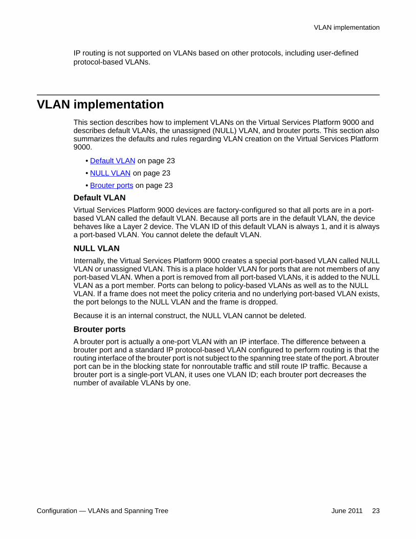
VLAN implementationThis section describes how to implement VLANs on the Virtual Services Platform 9000 anddescribes default VLANs, the unassigned (NULL) VLAN, and brouter ports. This section alsosummarizes the defaults and rules regarding VLAN creation on the Virtual Services Platform9000.
• Default VLAN on page 23• NULL VLAN on page 23• Brouter ports on page 23
Default VLANVirtual Services Platform 9000 devices are factory-configured so that all ports are in a port-based VLAN called the default VLAN. Because all ports are in the default VLAN, the devicebehaves like a Layer 2 device. The VLAN ID of this default VLAN is always 1, and it is alwaysa port-based VLAN. You cannot delete the default VLAN.
NULL VLANInternally, the Virtual Services Platform 9000 creates a special port-based VLAN called NULLVLAN or unassigned VLAN. This is a place holder VLAN for ports that are not members of anyport-based VLAN. When a port is removed from all port-based VLANs, it is added to the NULLVLAN as a port member. Ports can belong to policy-based VLANs as well as to the NULLVLAN. If a frame does not meet the policy criteria and no underlying port-based VLAN exists,the port belongs to the NULL VLAN and the frame is dropped.
Because it is an internal construct, the NULL VLAN cannot be deleted.
Brouter portsA brouter port is actually a one-port VLAN with an IP interface. The difference between abrouter port and a standard IP protocol-based VLAN configured to perform routing is that therouting interface of the brouter port is not subject to the spanning tree state of the port. A brouterport can be in the blocking state for nonroutable traffic and still route IP traffic. Because abrouter port is a single-port VLAN, it uses one VLAN ID; each brouter port decreases thenumber of available VLANs by one.
VLAN implementation
Configuration — VLANs and Spanning Tree June 2011 23
VLAN configuration rulesThe following are VLAN rules for the Virtual Services Platform 9000:
• The Virtual Services Platform 9000 can support up to 4084 configurable VLANS. VLANIDs range from 1 to 4084. VLAN IDs 4085 to 4094 are reserved for internal use.
• A tagged port can belong to multiple VLANs in multiple Spanning Tree Groups.
• Under the default configuration, the default Spanning Tree Group is number 1 if thechassis configuration permits multiple STGs.
• An untagged port can belong to only one port-based VLAN.
• You can configure only one protocol-based VLAN for a given protocol. Up to 16 protocol-based VLANs are supported, but see Table 3 for limitations.
• The VLAN membership of a frame is determined by the following order of precedence, ifapplicable:
a. IEEE 802.1Q tagged VLAN ID
b. IP subnet-based VLAN
c. source MAC-based VLAN
d. protocol-based VLAN
e. port-based VLAN default VLAN of the receiving port
• The IP subnet-based VLAN must not be assigned to a transit network (for example, anetwork routed to a bridged subnet).
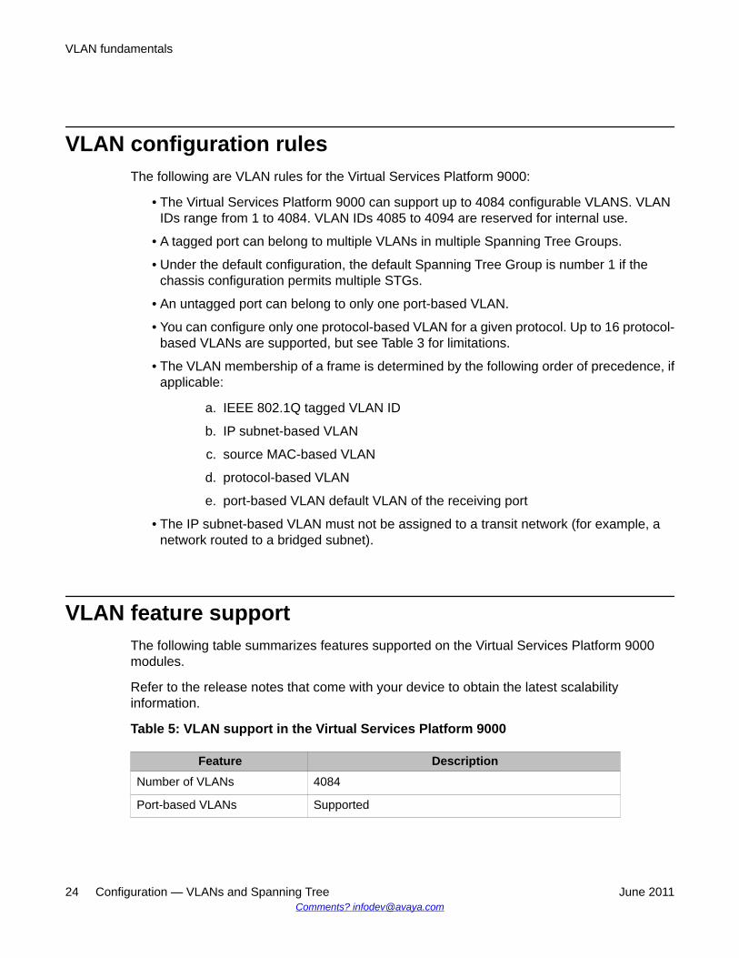
VLAN feature supportThe following table summarizes features supported on the Virtual Services Platform 9000modules.
Refer to the release notes that come with your device to obtain the latest scalabilityinformation.
Table 5: VLAN support in the Virtual Services Platform 9000
Feature DescriptionNumber of VLANs 4084
Port-based VLANs Supported
VLAN fundamentals
24 Configuration — VLANs and Spanning Tree June 2011Comments? [email protected]
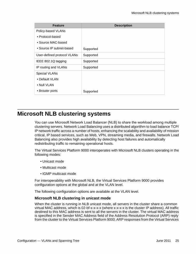
Feature DescriptionPolicy-based VLANs
• Protocol-based
• Source MAC-based
• Source IP subnet-based Supported
User-defined protocol VLANs Supported
IEEE 802.1Q tagging Supported
IP routing and VLANs Supported
Special VLANs
• Default VLAN
• Null VLAN
• Brouter ports Supported
Microsoft NLB clustering systemsYou can use Microsoft Network Load Balancer (NLB) to share the workload among multipleclustering servers. Network Load Balancing uses a distributed algorithm to load balance TCP/IP network traffic across a number of hosts, enhancing the scalability and availability of missioncritical, IP based services, such as Web, VPN, streaming media, and firewalls. Network LoadBalancing also provides high availability by detecting host failures and automaticallyredistributing traffic to remaining operational hosts.
The Virtual Services Platform 9000 interoperates with Microsoft NLB clusters operating in thefollowing modes:
• Unicast mode
• Multicast mode
• IGMP multicast mode
For interoperability with Microsoft NLB, the Virtual Services Platform 9000 providesconfiguration options at the global and at the VLAN level.
The following configuration options are available at the VLAN level.
Microsoft NLB clustering in unicast modeWhen the cluster is running in NLB unicast mode, all servers in the cluster share a commonvirtual MAC address, which is 02-bf-x-x-x-x (where x-x-x-x is the cluster IP address). All trafficdestined to this MAC address is sent to all the servers in the cluster. The virtual MAC addressis specified in the Sender MAC Address field of the Address Resolution Protocol (ARP) replyfrom the cluster to the Virtual Services Platform 9000. ARP responses from the Virtual Services
Microsoft NLB clustering systems
Configuration — VLANs and Spanning Tree June 2011 25
Platform 9000 are sent to the virtual MAC address (rather than to the hardware MACaddress).
You can configure Virtual Services Platform 9000 for NLB unicast mode support. After youenable the NLB unicast option, the Virtual Services Platform 9000 floods traffic destined to thecluster IP address to all ports on the VLAN.
Microsoft NLB clustering in multicast modeWhen the cluster is running in NLB multicast mode, a multicast virtual MAC address with theformat 03-bf-x-x-x-x (where x-x-x-x is the cluster IP address) is bound to all cluster hosts butthe real MAC address of the network adapter is retained. The multicast MAC address is usedfor client-to-cluster traffic and the real MAC address of the adapter is used for network trafficspecific to the host server.
You can configure Virtual Services Platform 9000 for NLB multicast mode support. If you enableNLB multicast mode, the Virtual Services Platform 9000 learns which ports on the VLAN aredirectly connected to cluster servers by using the ARP replies that the cluster sends. The VirtualServices Platform 9000 internally maps the NLB multicast MAC (03:bf:x:x:x:x) to the ports onwhich the ARP replies are received. Only VLAN ports with connected NLB servers are addedto the internal NLB MAC entries.
The Virtual Services Platform 9000 also uses the multicast MAC to create an ARP entry forthe NLB cluster.
Rather than flooding traffic destined to the cluster IP address to all ports on the VLAN, theVirtual Services Platform 9000 forwards cluster traffic only to the cluster ports.
Microsoft NLB clustering in IGMP-multicast modeWhen the cluster is running in NLB IGMP-multicast mode, a multicast virtual MAC address inthe format 01–00–5e–7f–x–x is bound to all cluster hosts and the real MAC address of thenetwork adapter is retained. In this case, the x-x at the end of the multicast virtual MAC addressare the last two bytes of the cluster IP address. The multicast MAC address is used for client-to-cluster traffic and the real MAC address is used for network traffic specific to the hostcomputer.
You can configure Virtual Services Platform 9000 for NLB IGMP-multicast mode support. If youenable NLB IGMP-multicast mode, the Virtual Services Platform 9000 learns the cluster portson the VLAN by using the IGMP reports that the cluster sends. The Virtual Services Platform9000 internally maps the NLB multicast MAC (01:00:5e:7f:x:x) to the ports on which the IGMPreports are received.
The Virtual Services Platform 9000 uses the multicast MAC to create an ARP entry for the NLBcluster.
Similar to multicast mode, rather than flooding traffic destined to the cluster IP address to allports on the VLAN, the Virtual Services Platform 9000 forwards cluster traffic only to the clusterports.
NLB multicast mode considerationsAfter you activate NLB multicast mode, the Virtual Services Platform 9000 does notautomatically show the cluster server ports in the NLB table. In multicast mode, the switch addsthe server ports to the NLB table based on the ARP replies it receives from the cluster hosts.
VLAN fundamentals
26 Configuration — VLANs and Spanning Tree June 2011Comments? [email protected]
NLB IGMP-multicast mode considerationsAfter you activate NLB IGMP-multicast mode, the Virtual Services Platform 9000 does notautomatically show the cluster server ports in the NLB table. In IGMP multicast mode, theswitch adds the server ports to the NLB table based on the IGMP reports it receives from thecluster hosts.
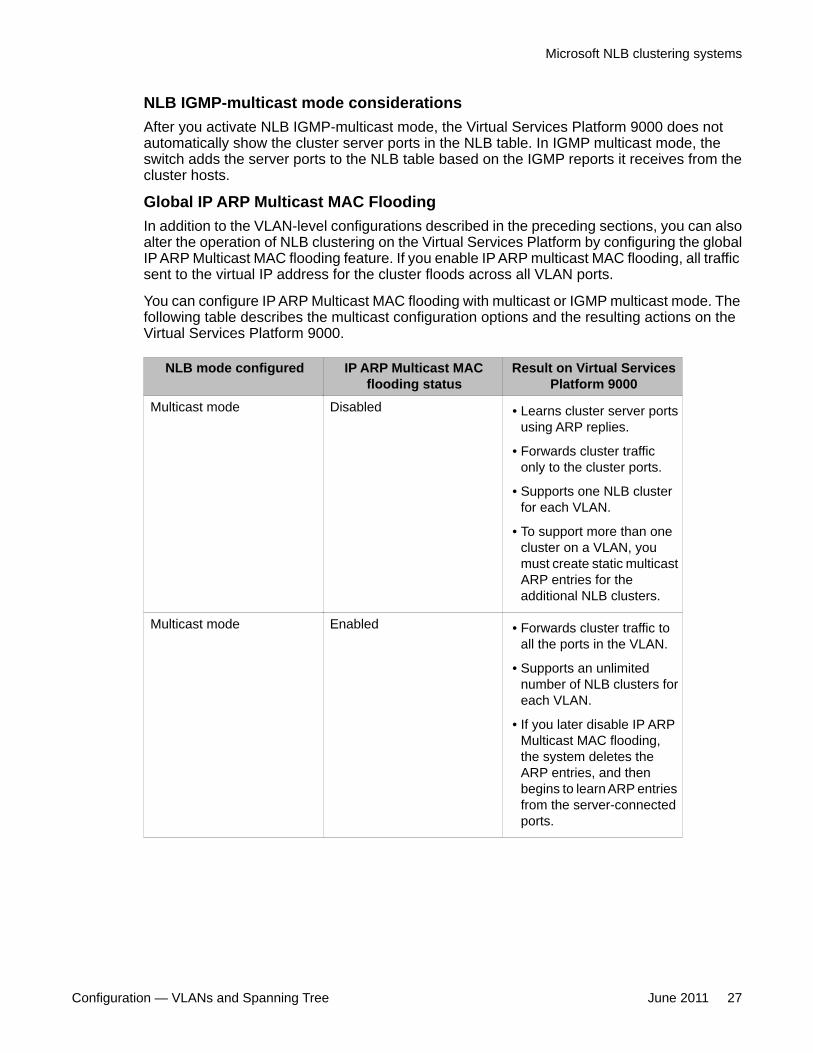
Global IP ARP Multicast MAC FloodingIn addition to the VLAN-level configurations described in the preceding sections, you can alsoalter the operation of NLB clustering on the Virtual Services Platform by configuring the globalIP ARP Multicast MAC flooding feature. If you enable IP ARP multicast MAC flooding, all trafficsent to the virtual IP address for the cluster floods across all VLAN ports.
You can configure IP ARP Multicast MAC flooding with multicast or IGMP multicast mode. Thefollowing table describes the multicast configuration options and the resulting actions on theVirtual Services Platform 9000.
NLB mode configured IP ARP Multicast MACflooding status
Result on Virtual ServicesPlatform 9000
Multicast mode Disabled • Learns cluster server portsusing ARP replies.
• Forwards cluster trafficonly to the cluster ports.
• Supports one NLB clusterfor each VLAN.
• To support more than onecluster on a VLAN, youmust create static multicastARP entries for theadditional NLB clusters.
Multicast mode Enabled • Forwards cluster traffic toall the ports in the VLAN.
• Supports an unlimitednumber of NLB clusters foreach VLAN.
• If you later disable IP ARPMulticast MAC flooding,the system deletes theARP entries, and thenbegins to learn ARP entriesfrom the server-connectedports.
Microsoft NLB clustering systems
Configuration — VLANs and Spanning Tree June 2011 27
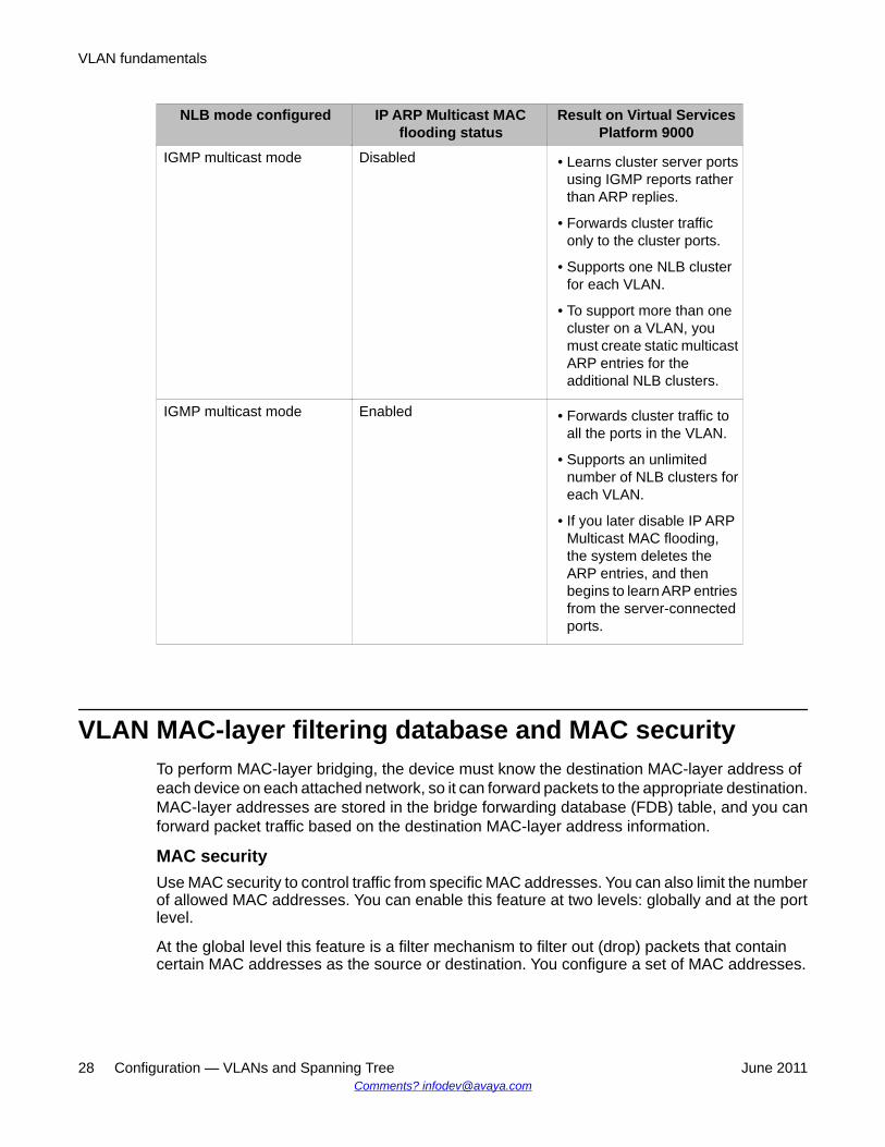
NLB mode configured IP ARP Multicast MACflooding status
Result on Virtual ServicesPlatform 9000
IGMP multicast mode Disabled • Learns cluster server portsusing IGMP reports ratherthan ARP replies.
• Forwards cluster trafficonly to the cluster ports.
• Supports one NLB clusterfor each VLAN.
• To support more than onecluster on a VLAN, youmust create static multicastARP entries for theadditional NLB clusters.
IGMP multicast mode Enabled • Forwards cluster traffic toall the ports in the VLAN.
• Supports an unlimitednumber of NLB clusters foreach VLAN.
• If you later disable IP ARPMulticast MAC flooding,the system deletes theARP entries, and thenbegins to learn ARP entriesfrom the server-connectedports.
VLAN MAC-layer filtering database and MAC securityTo perform MAC-layer bridging, the device must know the destination MAC-layer address ofeach device on each attached network, so it can forward packets to the appropriate destination.MAC-layer addresses are stored in the bridge forwarding database (FDB) table, and you canforward packet traffic based on the destination MAC-layer address information.
MAC securityUse MAC security to control traffic from specific MAC addresses. You can also limit the numberof allowed MAC addresses. You can enable this feature at two levels: globally and at the portlevel.
At the global level this feature is a filter mechanism to filter out (drop) packets that containcertain MAC addresses as the source or destination. You configure a set of MAC addresses.
VLAN fundamentals
28 Configuration — VLANs and Spanning Tree June 2011Comments? [email protected]
The system drops a packet that contains one of these configured addresses as the source ordestination.
Port-level MAC security provides more flexibility over the global configuration. Port—levelsecurity applies to traffic for all VLANs received on that port.
Port-level MAC security provides two options:
• unknown-discard: After you enable this feature, the port drops received packets with anunknown source MAC address and adds the MAC addresses to the FDB table with thestatus of discard. This option provides some control over the number of MAC addressesthat are learned and forwarded:
- allow-mac: You can configure a group of MAC addresses. The port processespackets that match these MAC addresses even if you enable unknown-mac-discard.
- auto-learning: Configure a number of MAC addresses for the port to learn, even ifyou enable unknown-mac-discard. The port learns source MAC addresses forreceived packets up to a maximum value that you configure. After the number ofaddresses exceeds the maximum value, the port discards packets and does notlearn more MAC addresses until an existing address ages out of the table.
- auto-learning learning-mode: Specifies the learning mode as one of the following:• one-shot: The autolearned addresses do not age out. When the VLAN mac-
address entry is flushed, the auto-learned addresses are not flushed.• continuous: In continuous mode the aging of the auto-learned MAC is subject
to the normal aging. When the VLAN MAC address entry is flushed, the auto-learned addresses are also flushed.
- lock-learning-MAC: If this option is enabled then no MAC addresses will be auto-learned. The port will drop packets that it receives and add the MAC addresses tothe FDB table with the status of discarded.
• limit-learning: This option protects the FDB from traffic from too many MAC addresses,which fill the FDB table.
This option limits the number of MAC addresses a port learns. You can specify a maximumand minimum number of addresses. After the number of addresses exceeds themaximum, learning stops. MAC address learning resumes after enough existingaddresses age out that only the minimum number of addresses remain. This option doesnot affect packet forwarding; it limits only MAC learning.
Important:Do not enable limit-learning and auto-learning for a port simultaneously.
Prevention of IP spoofing within a VLANYou can prevent VLAN logical IP spoofing by blocking the external use of the device IP address.A configurable option is provided, for each port, which detects a duplicate IP address (that is,
Prevention of IP spoofing within a VLAN
Configuration — VLANs and Spanning Tree June 2011 29
an address that is the same as the device VLAN IP address) and blocks all packets with asource or destination address equal to that address.
If an ARP packet is received that has the same source IP address as the logical VLAN IPaddress of the receiving port, all traffic coming to that port (with this MAC address as source/destination address) is discarded by the hardware. After detecting a duplicate IP address, thedevice sends a gratuitous ARP packet to inform devices on the VLAN about the correct MACaddress for that IP address. You can specify a time on a configurable global timer after whichthe MAC discard record is deleted, and the device resumes accepting packets from that MACaddress.
If you use Split MultiLink Trunking (SMLT), configure this option on both SMLT aggregationdevices to avoid connectivity issues.
Important:After you enable the IP spoofing feature, you must restart the device.
VLAN loop detectionThe loop detection feature is used at the edge of a network to prevent loops. It detects whetherpackets with the same source MAC address for a VLAN are received on different ports. If thesame MAC address for the same VLAN is detected on two different ports five times in aconfigurable amount of time, a configured loop detect action is performed.
The loop detection feature also offers an optional parameter, known as ARP detect, to detectLayer 3 loops.
Enable the loop detection feature on SMLT ports. Do no use loop-detect on IST ports or coreSMLT square or full mesh ports.
Important:If you attempt to enable loop-detect on an existing IST port, the system prevents you fromdoing so. However, if you have a port with loop-detect already enabled, and you add thatport to an IST, the system does not prevent you from doing so, causing potential systemerrors.
The loop detection feature is configured for each device. If a loop detection event takes place,peer devices are not notified.
The loop detection feature has the following traits:
• If a source MAC address is found to loop, and the specified loop detect action is MAC-discard, the MAC address is disabled. The incoming packets with this source ordestination MAC address can be discarded for that VLAN.
• If a source MAC address is found to loop, and the specified loop detect action is PortDown, the port on which the loop was detected is disabled.
VLAN fundamentals
30 Configuration — VLANs and Spanning Tree June 2011Comments? [email protected]
• Ports and MAC addresses that have been disabled by the loop detection feature arereenabled for automatic recovery.
• The link flap feature configures ports to operational down rather than admin down.
• Loop detection cannot be enabled on interswitch trunk ports.
To detect loops on a VLAN, the Virtual Services Platform 9000 also supports Simple LoopPrevention Protocol. Simple Loop Prevention Protocol (SLPP) provides active protectionagainst Layer 2 network loops on a per-VLAN basis. SLPP uses a lightweight hello packetmechanism to detect network loops. SLPP can detect VLAN-based network loops for un-tagged as well as tagged IEEE 802.1Q VLAN link configurations.
For more information on SLPP, see Avaya Virtual Services Platform 9000 Administrationdocument (NN46250-600).
VLAN loop detection
Configuration — VLANs and Spanning Tree June 2011 31
Chapter 4: Spanning tree fundamentals
This section describes the spanning tree features supported on the Avaya Virtual Services Platform9000.
Virtual Services Platform 9000 supports Rapid Spanning Tree Protocol (RSTP) and Multiple SpanningTree Protocol (MSTP).
• Spanning tree on page 33• Rapid Spanning Tree Protocol and Multiple Spanning Tree Protocol on page 34
Spanning treeSpanning Tree protocols detect and eliminate logical loops in a bridged or switched network. If multiplepaths exist, the spanning tree algorithm configures the network so that a bridge or device uses the rootbridge path based on hop counts. Although link speed is taken into account, the path is based on the rootbridge rather than on an optimized path. If that path fails, the protocol automatically reconfigures thenetwork and makes another path active, thereby sustaining network operations. Virtual Services Platform9000 supports RSTP and MSTP but can downgrade a port automatically if it receives an STP BridgeProtocol Data Unit (BPDU) from a switch that runs STP.
Spanning Tree GroupsSpanning Tree Groups (STGs) represent logical topologies. A topology is created based on bridgeconfiguration values such as root bridge priority. In the case of multiple STGs, you can map a VLAN tothe most appropriate logical topology in the physical network.
The Virtual Services Platform 9000 supports spanning-tree modes RSTP and MSTP. The defaultspanning-tree mode is MSTP. The default STG is 0. In RSTP mode all VLANs run in the default STG. InMSTP mode, you can create additional STGs by using the VLAN create command. The Virtual ServicesPlatform 9000 supports up to 64 STGs.
The root bridge for Rapid Spanning Tree Protocol (RSTP) and Multiple Spanning Tree Protocol (MSTP)is determined by comparing attributes of each bridge in the network.
The protocol considers bridge priority first. If more than one bridge has the same priority, then the protocolmust consider the bridge ID. The bridge with the lowest ID becomes the root bridge. For MSTP, this bridgeis called the Common and Internal Spanning Tree (CIST) Root because it is the root of the entire physicalnetwork.
In MSTP mode, you can create additional Spanning Tree instances, by using the VLAN command. Theseinstances, known as Multiple Spanning Tree Instances (MSTIs), may assign different priorities to switches.The MSTIs have different link costs or port priorities and as a result create separate logical topologies.
MSTP also allows the creation of MSTP regions. A region is a collection of switches sharing the sameview of physical and logical topologies. For switches to belong to the same region, the following attributesmust match:
Configuration — VLANs and Spanning Tree June 2011 33
• MSTP configuration ID selector• MSTP configuration name• MSTP configuration revision number• VLAN instance mapping
Links connecting sections are called boundary ports. In a region, the boundary switch that contains theboundary port providing the shortest external path cost to the CIST Root is the CIST Regional Root.
STGs and VLANsWhen you map VLANs to STGs, be aware that all links on the bridge belong to all STGs. Because eachSpanning Tree group can differ in its decision to make a link forwarding or blocking, you must ensure thatthe ports you add to a VLAN are in the expected state.
Untagged ports can only belong to one VLAN and therefore to only one STG. Tagged ports can belongto multiple VLANs and therefore to multiple STGs.
Rapid Spanning Tree Protocol and Multiple Spanning TreeProtocol
The Rapid Spanning Tree Protocol (RSTP or IEEE 802.1w) reduces the recovery time after anetwork breakdown. It also maintains backward compatibility with IEEE 802.1d (the spanningtree implementation prior to RSTP). In certain configurations, the recovery time of RSTP canbe reduced to less than 1 second. RSTP also reduces the amount of flooding in the networkby enhancing the way Topology Change Notification (TCN) packets are generated.
With Multiple Spanning Tree Protocol (MSTP or IEEE 802.1s), you can configure multipleinstances or Spanning Tree groups on the same device. Each instance or Spanning Tree groupcan include one or more VLANs.
By using RSTP and MSTP, the Virtual Services Platform 9000 achieves the following:
• reduce convergence time after a topology change (from 30 seconds to less than 1 or 2seconds)
• eliminate unnecessary flushing of the MAC database and the flooding of traffic to thenetwork
• create backward compatibility with classic 802.1d switches• create support for 64 instances of spanning tree in MSTP mode
The following sections relate to RSTP and MSTP:
• RSTP interoperability with STP on page 35• Differences in port roles for STP and RSTP on page 35• Port roles: root forwarding role on page 36• Port roles: designated forwarding role on page 36
Spanning tree fundamentals
34 Configuration — VLANs and Spanning Tree June 2011Comments? [email protected]
• Port roles: alternate blocking role on page 36• Edge port on page 36• Path cost values on page 36• RSTP negotiation process on page 37
RSTP interoperability with STPRSTP provides a parameter called ForceVersion to provide backward compatibility withstandard STP. A user can configure a port in either STP-compatible mode or RSTP mode:
• An STP-compatible port transmits and receives only STP Bridge Protocol Data Units(BPDUs). An RSTP BPDU that the port receives in this mode is discarded.
• An RSTP-compatible port transmits and receives only RSTP BPDUs. If an RSTP portreceives an STP BPDU, it becomes an STP port. User intervention is required to changethis port back to RSTP mode. This process is called Port Protocol Migration.
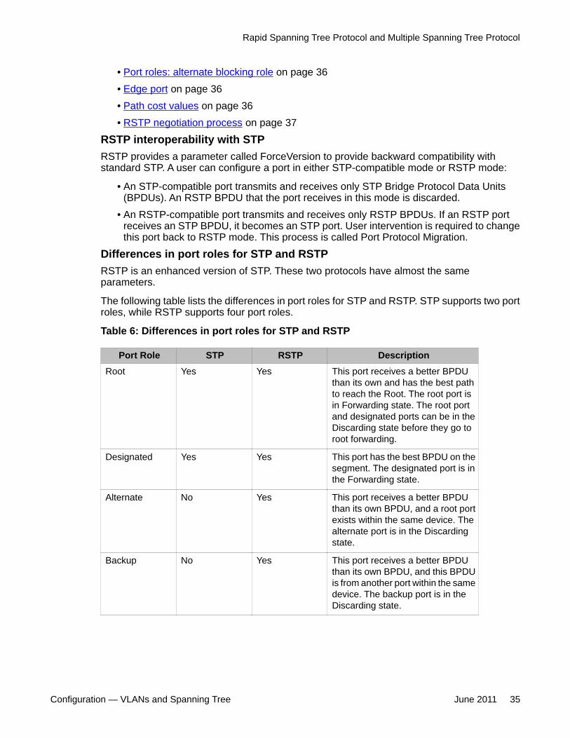
Differences in port roles for STP and RSTPRSTP is an enhanced version of STP. These two protocols have almost the sameparameters.
The following table lists the differences in port roles for STP and RSTP. STP supports two portroles, while RSTP supports four port roles.
Table 6: Differences in port roles for STP and RSTP
Port Role STP RSTP DescriptionRoot Yes Yes This port receives a better BPDU
than its own and has the best pathto reach the Root. The root port isin Forwarding state. The root portand designated ports can be in theDiscarding state before they go toroot forwarding.
Designated Yes Yes This port has the best BPDU on thesegment. The designated port is inthe Forwarding state.
Alternate No Yes This port receives a better BPDUthan its own BPDU, and a root portexists within the same device. Thealternate port is in the Discardingstate.
Backup No Yes This port receives a better BPDUthan its own BPDU, and this BPDUis from another port within the samedevice. The backup port is in theDiscarding state.
Rapid Spanning Tree Protocol and Multiple Spanning Tree Protocol
Configuration — VLANs and Spanning Tree June 2011 35
Port roles: root forwarding roleMSTP and RSTP root forwarding roles are as follows:
• The port that receives the best path BPDU on a device is the root port, and is referred toas a Root Forwarding (RF) port. This is the port that is the closest to the root bridge interms of path cost.
• The spanning tree algorithm elects a single root bridge in a bridged network. With MSTP,a root bridge is selected for the Common and Internal Spanning Tree (CIST). A root bridgeis selected for the region, and a root bridge is selected for each spanning tree instance.
• The root bridge is the only bridge in a network that does not have root ports; all ports ona root bridge are Designated Forwarding (DF).
• Only one path towards a root bridge can exist on a given segment; otherwise, loops canoccur.
Port roles: designated forwarding roleMSTP and RSTP designated forwarding roles are as follows:
• All bridges connected on a segment monitor the BPDUs of all other bridges. The bridgethat sends the best BPDU is the root bridge for the segment.
• The corresponding port on the bridge is referred to as a Designated Forwarding Port.
Port roles: alternate blocking roleMSTP and RSTP alternate blocking roles are as follows:
• A blocked port is defined as not being the designated or root port. An alternate portprovides an alternate path to the root and can replace the root port if it fails.
• An alternate blocked port is a port that is blocked because it received better path costBPDUs from another bridge.
Port roles: backup blocking roleMSTP and RSTP backup blocking roles are as follows:
A backup port receives the more useful BPDUs from the bridge on which the port exists.
Edge portRSTP uses a parameter called the edge port. After a port connects to a nonswitch device, suchas a PC or a workstation, it must be configured as an edge port. An active edge port entersthe forwarding state without delay. An edge port becomes a nonedge port if it receives aBPDU.
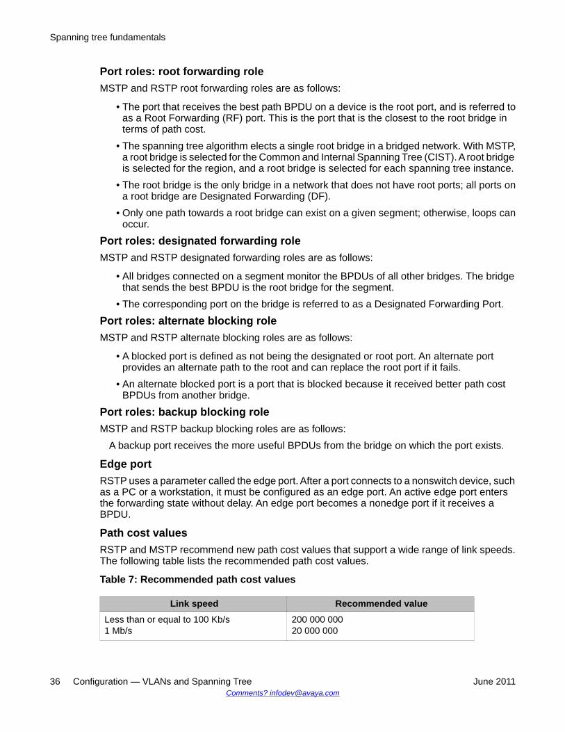
Path cost valuesRSTP and MSTP recommend new path cost values that support a wide range of link speeds.The following table lists the recommended path cost values.
Table 7: Recommended path cost values
Link speed Recommended valueLess than or equal to 100 Kb/s1 Mb/s
200 000 00020 000 000
Spanning tree fundamentals
36 Configuration — VLANs and Spanning Tree June 2011Comments? [email protected]
Link speed Recommended value10 Mb/s100 Mb/s
2 000 000200 000
1 Gb/s10 Gb/s100 Gb/s
20 0002000200
1 Tb/s10 Tb/s
202
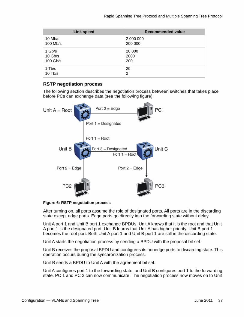
RSTP negotiation processThe following section describes the negotiation process between switches that takes placebefore PCs can exchange data (see the following figure).
Figure 6: RSTP negotiation process
After turning on, all ports assume the role of designated ports. All ports are in the discardingstate except edge ports. Edge ports go directly into the forwarding state without delay.
Unit A port 1 and Unit B port 1 exchange BPDUs. Unit A knows that it is the root and that UnitA port 1 is the designated port. Unit B learns that Unit A has higher priority. Unit B port 1becomes the root port. Both Unit A port 1 and Unit B port 1 are still in the discarding state.
Unit A starts the negotiation process by sending a BPDU with the proposal bit set.
Unit B receives the proposal BPDU and configures its nonedge ports to discarding state. Thisoperation occurs during the synchronization process.
Unit B sends a BPDU to Unit A with the agreement bit set.
Unit A configures port 1 to the forwarding state, and Unit B configures port 1 to the forwardingstate. PC 1 and PC 2 can now communicate. The negotiation process now moves on to Unit
Rapid Spanning Tree Protocol and Multiple Spanning Tree Protocol
Configuration — VLANs and Spanning Tree June 2011 37
B port 3 and its partner port. PC 3 cannot exchange data with either PC 1 or PC 2 until thenegotiation process between Unit B and Unit C finishes.
The RSTP convergence time depends on how quickly the Virtual Services Platform 9000 canexchange BPDUs during the negotiation process, and on the number of switches in thenetwork.
Spanning tree fundamentals
38 Configuration — VLANs and Spanning Tree June 2011Comments? [email protected]
Chapter 5: VLAN configuration usingEnterprise Device Manager
This chapter describes how to configure and manage Virtual Local Area Networks (VLAN) using EnterpriseDevice Manager (EDM).
• Configuring the VLAN feature on a port on page 40
• Viewing existing VLANs on page 42
• Viewing ports in a null VLAN on page 42
• Creating a port-based VLAN on page 43
• Configuring an IP address for a VLAN on page 46
• Changing VLAN port membership on page 47
• Creating a source IP subnet-based VLAN on page 48
• Creating a protocol-based VLAN on page 49
• Configuring user-defined protocol-based VLANs on page 50
• Configuring a source MAC address-based VLAN on page 52
• Configuring source MAC addresses for a source MAC-based VLAN on page 53
• Configuring advanced VLAN features on page 54
• Configuring NLB support on page 57
• Configuring a port to accept tagged or untagged frames on page 58
• Configuring untagging default VLAN on a tagged port on page 59
• Configuring VLAN loop detection on page 59
• Configuring directed broadcast on a VLAN on page 60
• Configuring the forwarding database timeout on page 61
• Viewing VLAN forwarding database information on page 62
• Viewing the forwarding database for a specific VLAN on page 63
• Clearing learned MAC addresses by VLAN on page 64
• Clearing learned MAC addresses for all VLANs by port on page 65
• Configuring static forwarding on page 65
• Configuring static multicast for a bridge on page 66
Configuration — VLANs and Spanning Tree June 2011 39
• Enabling global MAC security on page 67
• Configuring multiple DSAPs and SSAPs on page 68
• Enabling unknown MAC discard on page 69
• Configuring MAC learning parameters on page 69
• Configuring MAC address learning on page 71
• Modifying auto-learned MAC addresses on page 72
• Configuring limit learning on page 73
Configuring the VLAN feature on a portAbout this taskConfigure the VLAN feature on a port.
1. In the Device Physical View tab, select a port or multiple ports.
2. In the Navigation tree, open the following folders: Configuration > Edit > Port
3. Click General.
4. Click the VLAN tab.
5. To perform tagging, select PerformTagging.
6. To discard tagged frames, select DiscardTaggedFrames.
7. To discard untagged frames, select DiscardUntaggedFrames.
8. To use the Untag Default VLAN feature, select UntagDefaultVlan.
Important:Avaya recommends that you enable tagging on the port before you configureUntagDefaultVlans.
9. Enter a default VLAN ID.
10. To enable loop detection, select LoopDetect.
11. To enable the ARP loop detection feature on this port, select ARPDetect.
12. To specify the action that needs to be taken after a MAC loop is detected on aspecific port, select portDown or macDiscard.
Important:You can only use this feature if you also select LoopDetect.
13. In the Classification area, select the types of VLAN to enable.
VLAN configuration using Enterprise Device Manager
40 Configuration — VLANs and Spanning Tree June 2011Comments? [email protected]
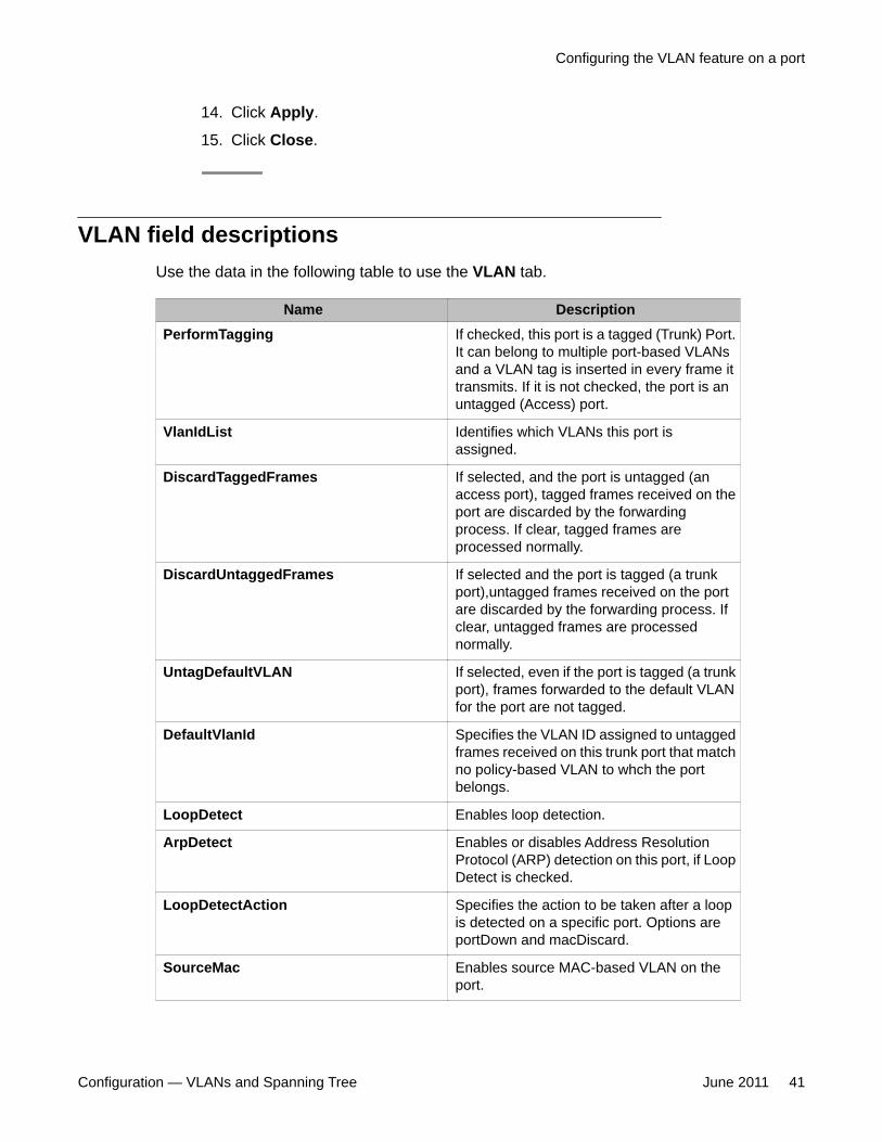
14. Click Apply.
15. Click Close.
VLAN field descriptionsUse the data in the following table to use the VLAN tab.
Name DescriptionPerformTagging If checked, this port is a tagged (Trunk) Port.
It can belong to multiple port-based VLANsand a VLAN tag is inserted in every frame ittransmits. If it is not checked, the port is anuntagged (Access) port.
VlanIdList Identifies which VLANs this port isassigned.
DiscardTaggedFrames If selected, and the port is untagged (anaccess port), tagged frames received on theport are discarded by the forwardingprocess. If clear, tagged frames areprocessed normally.
DiscardUntaggedFrames If selected and the port is tagged (a trunkport),untagged frames received on the portare discarded by the forwarding process. Ifclear, untagged frames are processednormally.
UntagDefaultVLAN If selected, even if the port is tagged (a trunkport), frames forwarded to the default VLANfor the port are not tagged.
DefaultVlanId Specifies the VLAN ID assigned to untaggedframes received on this trunk port that matchno policy-based VLAN to whch the portbelongs.
LoopDetect Enables loop detection.
ArpDetect Enables or disables Address ResolutionProtocol (ARP) detection on this port, if LoopDetect is checked.
LoopDetectAction Specifies the action to be taken after a loopis detected on a specific port. Options areportDown and macDiscard.
SourceMac Enables source MAC-based VLAN on theport.
Configuring the VLAN feature on a port
Configuration — VLANs and Spanning Tree June 2011 41
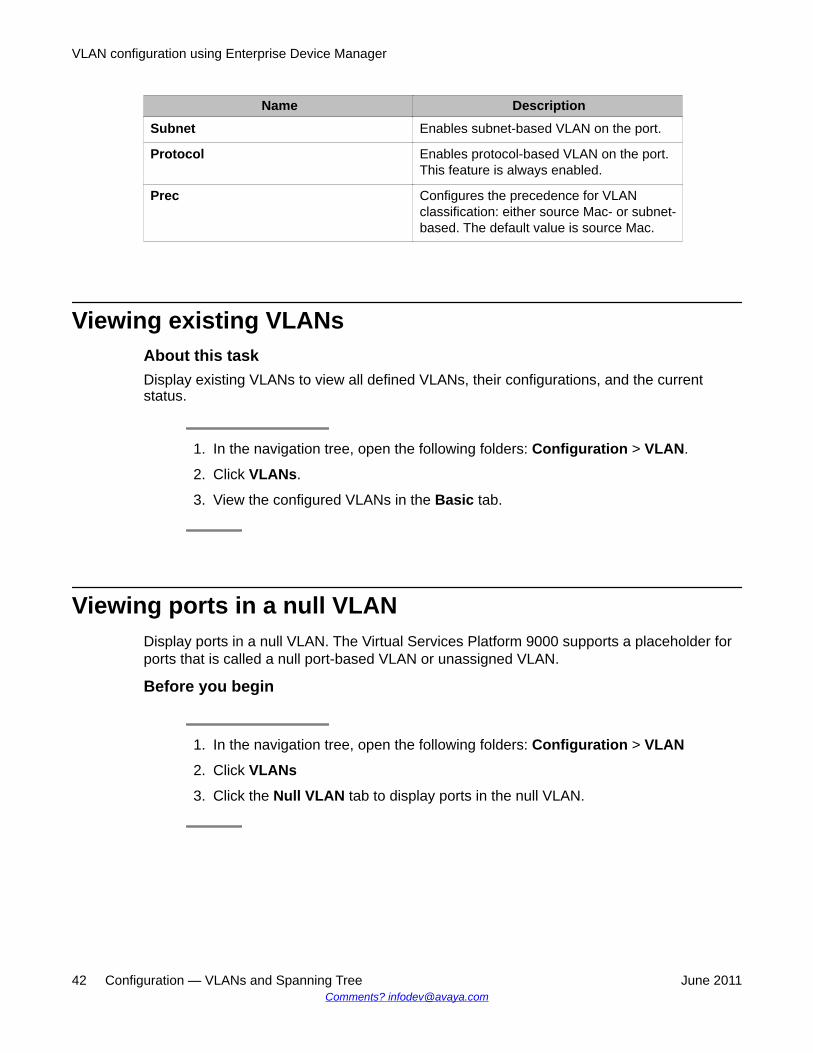
Name DescriptionSubnet Enables subnet-based VLAN on the port.
Protocol Enables protocol-based VLAN on the port.This feature is always enabled.
Prec Configures the precedence for VLANclassification: either source Mac- or subnet-based. The default value is source Mac.
Viewing existing VLANsAbout this taskDisplay existing VLANs to view all defined VLANs, their configurations, and the currentstatus.
1. In the navigation tree, open the following folders: Configuration > VLAN.
2. Click VLANs.
3. View the configured VLANs in the Basic tab.
Viewing ports in a null VLANDisplay ports in a null VLAN. The Virtual Services Platform 9000 supports a placeholder forports that is called a null port-based VLAN or unassigned VLAN.
Before you begin
1. In the navigation tree, open the following folders: Configuration > VLAN
2. Click VLANs
3. Click the Null VLAN tab to display ports in the null VLAN.
VLAN configuration using Enterprise Device Manager
42 Configuration — VLANs and Spanning Tree June 2011Comments? [email protected]
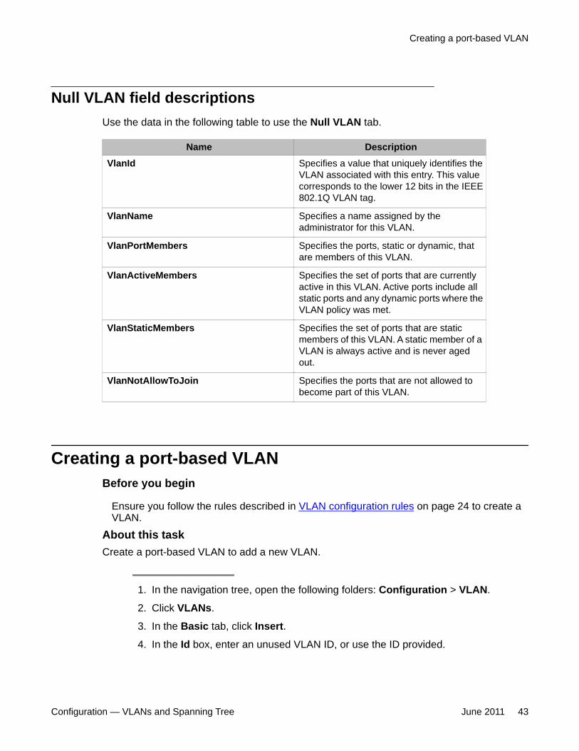
Null VLAN field descriptionsUse the data in the following table to use the Null VLAN tab.
Name DescriptionVlanId Specifies a value that uniquely identifies the
VLAN associated with this entry. This valuecorresponds to the lower 12 bits in the IEEE802.1Q VLAN tag.
VlanName Specifies a name assigned by theadministrator for this VLAN.
VlanPortMembers Specifies the ports, static or dynamic, thatare members of this VLAN.
VlanActiveMembers Specifies the set of ports that are currentlyactive in this VLAN. Active ports include allstatic ports and any dynamic ports where theVLAN policy was met.
VlanStaticMembers Specifies the set of ports that are staticmembers of this VLAN. A static member of aVLAN is always active and is never agedout.
VlanNotAllowToJoin Specifies the ports that are not allowed tobecome part of this VLAN.
Creating a port-based VLANBefore you begin
Ensure you follow the rules described in VLAN configuration rules on page 24 to create aVLAN.
About this taskCreate a port-based VLAN to add a new VLAN.
1. In the navigation tree, open the following folders: Configuration > VLAN.
2. Click VLANs.
3. In the Basic tab, click Insert.
4. In the Id box, enter an unused VLAN ID, or use the ID provided.
Creating a port-based VLAN
Configuration — VLANs and Spanning Tree June 2011 43
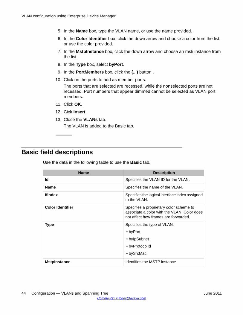
5. In the Name box, type the VLAN name, or use the name provided.
6. In the Color Identifier box, click the down arrow and choose a color from the list,or use the color provided.
7. In the MstpInstance box, click the down arrow and choose an msti instance fromthe list.
8. In the Type box, select byPort.
9. In the PortMembers box, click the (...) button .
10. Click on the ports to add as member ports.The ports that are selected are recessed, while the nonselected ports are notrecessed. Port numbers that appear dimmed cannot be selected as VLAN portmembers.
11. Click OK.
12. Cick Insert.
13. Close the VLANs tab.The VLAN is added to the Basic tab.
Basic field descriptionsUse the data in the following table to use the Basic tab.
Name DescriptionId Specifies the VLAN ID for the VLAN.
Name Specifies the name of the VLAN.
IfIndex Specifies the logical interface index assignedto the VLAN.
Color Identifier Specifies a proprietary color scheme toassociate a color with the VLAN. Color doesnot affect how frames are forwarded.
Type Specifies the type of VLAN:
• byPort
• byIpSubnet
• byProtocolId
• bySrcMac
MstpInstance Identifies the MSTP instance.
VLAN configuration using Enterprise Device Manager
44 Configuration — VLANs and Spanning Tree June 2011Comments? [email protected]
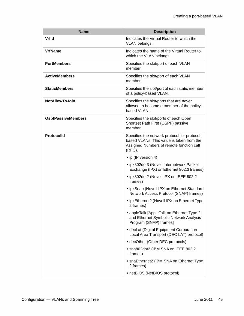
Name DescriptionVrfId Indicates the Virtual Router to which the
VLAN belongs.
VrfName Indicates the name of the Virtual Router towhich the VLAN belongs.
PortMembers Specifies the slot/port of each VLANmember.
ActiveMembers Specifies the slot/port of each VLANmember.
StaticMembers Specifies the slot/port of each static memberof a policy-based VLAN.
NotAllowToJoin Specifies the slot/ports that are neverallowed to become a member of the policy-based VLAN.
OspfPassiveMembers Specifies the slot/ports of each OpenShortest Path First (OSPF) passivemember.
ProtocolId Specifies the network protocol for protocol-based VLANs. This value is taken from theAssigned Numbers of remote function call(RFC).
• ip (IP version 4)
• ipx802dot3 (Novell Internetwork PacketExchange (IPX) on Ethernet 802.3 frames)
• ipx802dot2 (Novell IPX on IEEE 802.2frames)
• ipxSnap (Novell IPX on Ethernet StandardNetwork Access Protocol (SNAP) frames)
• ipxEthernet2 (Novell IPX on Ethernet Type2 frames)
• appleTalk [AppleTalk on Ethernet Type 2and Ethernet Symbolic Network AnalysisProgram (SNAP) frames]
• decLat (Digital Equipment CorporationLocal Area Transport (DEC LAT) protocol)
• decOther (Other DEC protocols)
• sna802dot2 (IBM SNA on IEEE 802.2frames)
• snaEthernet2 (IBM SNA on Ethernet Type2 frames)
• netBIOS (NetBIOS protocol)
Creating a port-based VLAN
Configuration — VLANs and Spanning Tree June 2011 45
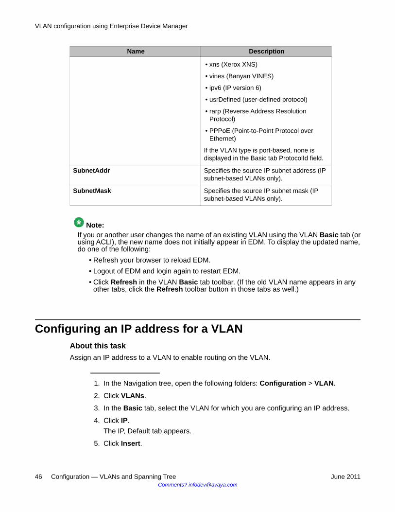
Name Description
• xns (Xerox XNS)
• vines (Banyan VINES)
• ipv6 (IP version 6)
• usrDefined (user-defined protocol)
• rarp (Reverse Address ResolutionProtocol)
• PPPoE (Point-to-Point Protocol overEthernet)
If the VLAN type is port-based, none isdisplayed in the Basic tab ProtocolId field.
SubnetAddr Specifies the source IP subnet address (IPsubnet-based VLANs only).
SubnetMask Specifies the source IP subnet mask (IPsubnet-based VLANs only).
Note:If you or another user changes the name of an existing VLAN using the VLAN Basic tab (orusing ACLI), the new name does not initially appear in EDM. To display the updated name,do one of the following:
• Refresh your browser to reload EDM.• Logout of EDM and login again to restart EDM.• Click Refresh in the VLAN Basic tab toolbar. (If the old VLAN name appears in any
other tabs, click the Refresh toolbar button in those tabs as well.)
Configuring an IP address for a VLANAbout this taskAssign an IP address to a VLAN to enable routing on the VLAN.
1. In the Navigation tree, open the following folders: Configuration > VLAN.
2. Click VLANs.
3. In the Basic tab, select the VLAN for which you are configuring an IP address.
4. Click IP.The IP, Default tab appears.
5. Click Insert.
VLAN configuration using Enterprise Device Manager
46 Configuration — VLANs and Spanning Tree June 2011Comments? [email protected]
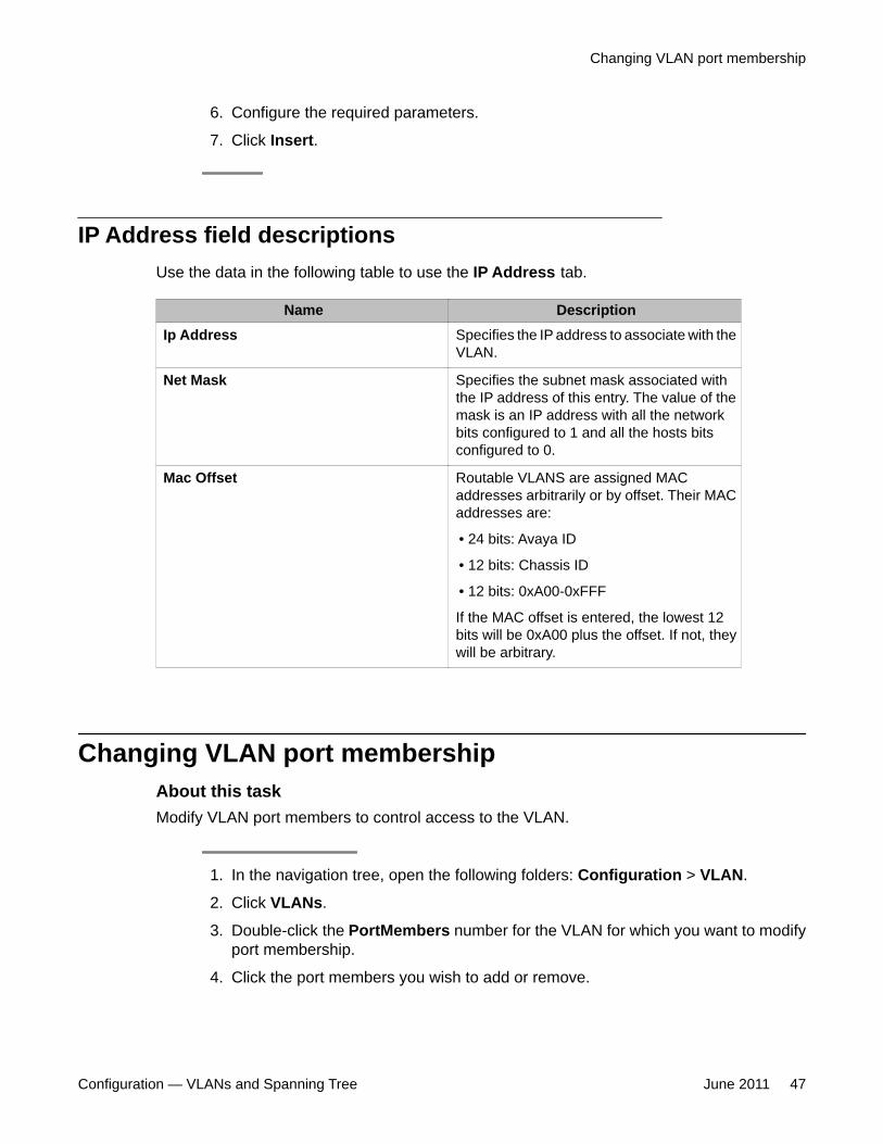
6. Configure the required parameters.
7. Click Insert.
IP Address field descriptionsUse the data in the following table to use the IP Address tab.
Name DescriptionIp Address Specifies the IP address to associate with the
VLAN.
Net Mask Specifies the subnet mask associated withthe IP address of this entry. The value of themask is an IP address with all the networkbits configured to 1 and all the hosts bitsconfigured to 0.
Mac Offset Routable VLANS are assigned MACaddresses arbitrarily or by offset. Their MACaddresses are:
• 24 bits: Avaya ID
• 12 bits: Chassis ID
• 12 bits: 0xA00-0xFFF
If the MAC offset is entered, the lowest 12bits will be 0xA00 plus the offset. If not, theywill be arbitrary.
Changing VLAN port membershipAbout this taskModify VLAN port members to control access to the VLAN.
1. In the navigation tree, open the following folders: Configuration > VLAN.
2. Click VLANs.
3. Double-click the PortMembers number for the VLAN for which you want to modifyport membership.
4. Click the port members you wish to add or remove.
Changing VLAN port membership
Configuration — VLANs and Spanning Tree June 2011 47
5. Click Ok.
6. Click Apply.The VLAN port membership is changed.
Creating a source IP subnet-based VLANAbout this taskCreate a source IP subnet-based VLAN so that a potential member becomes an active memberof the VLAN if a frame is received from the specified source IP address.
1. In the navigation tree, open the following folders: Configuration > VLAN.
2. Click VLANs.
3. In the Basic tab, click Insert.
4. In the Id box, type the VLAN ID.
5. In the Name box, type the VLAN name.If a name is not entered, a default name is created.
6. In the Color Identifier box, select a color or use the color provided.This color is used by VLAN Manager to visually distinguish the VLANs in anetwork.
7. In the MstpInstance box, click the down arrow and choose an MSTI instance fromthe list.
8. In the Type box, select byIpSubnet.The fields needed to configure IP subnet-based VLANs are activated.
9. To specify the VLAN port membership, click the ellipsis button (...) for one of thefollowing fields:PortMembersORStaticMembersORNotAllowToJoin
10. Click on each port to choose the desired color:Yellow—Potential membersor
VLAN configuration using Enterprise Device Manager
48 Configuration — VLANs and Spanning Tree June 2011Comments? [email protected]
Green—Always members, staticorRed—Never members, not allowed to join
Important:In a source IP subnet-based VLAN, a potential member becomes an activemember of the VLAN after a frame is received from an address on the specifiedIP network.
11. Click OK.
12. In the SubnetAddr box, enter an IP address for the VLAN.
13. In the SubnetMask box, enter an IP subnet mask for the VLAN.
14. In the AgingTime box, enter the timeout period in seconds for aging out the dynamicVLAN member ports or use the default.
15. Click Insert.
16. Close the VLANs tab.The subnet-based VLAN is added to the Basic tab.
Creating a protocol-based VLANAbout this taskUse a protocol-based VLAN so that the VLAN only carries certain traffic types.
1. In the navigation tree, open the following folders: Configuration > VLAN.
2. Click VLANs.
3. In the Basic tab, click Insert.
4. In the Id box, type the unique VLAN ID or use the ID provided.
5. In the Name box, type the VLAN name or use the name provided.
6. In the Color Identifier box, select the color or use the color provided.This color is used by VLAN Manager to visually distinguish the VLANs in anetwork.
7. In the MstpInstance box, click the down arrow and choose an MSTI instance fromthe list.
8. In the Type box, select byProtocolId.This activates additional fields needed to configure protocol-based VLANs.
Creating a protocol-based VLAN
Configuration — VLANs and Spanning Tree June 2011 49
9. To specify the VLAN port membership, click the button (...) for one of the followingfields:Port MembersORStaticMembersORNotAllowToJoin
10. Click each port button to choose the desired membership color.Yellow: Potential members—dynamic (potential members are treated as alwaysmembers)ORGreen: Always members—staticORRed: Never members—not allowed to join
Important:In a protocol-based VLAN for a Virtual Services Platform 9000, a potentialmember becomes an active member of the VLAN after a frame of the specifiedprotocol is received.
11. Click OK.
12. In the ProtocolId box, select a protocol ID.
13. In the AgingTime box, specify the timeout period, in seconds, for aging out thedynamic member ports of the VLAN or use the default.
14. Click Insert.
15. Close the VLANs tab.The protocol-based VLAN is added to the Basic tab.
Configuring user-defined protocol-based VLANsAbout this taskConfigure user-defined protocol-based VLANs to support the networks with nonstandardprotocols.
VLAN configuration using Enterprise Device Manager
50 Configuration — VLANs and Spanning Tree June 2011Comments? [email protected]
1. In the navigation tree, open the following folders: Configuration > VLAN.
2. Click VLANs.
3. On the Basic tab, click Insert.
4. In the Type box, select byProtocolId.
5. To specify the VLAN port membership, click the button (...) for one of the followingfields:Port MembersORStaticMembersORNotAllowedToJoin
6. Click each port button to achieve the desired membership color:Yellow: Potential members—dynamic.ORGreen: Always members—staticORRed: Never members—not allowed to join
Important:In a user-defined protocol-based VLAN on a Virtual Services Platform 9000module, a potential member becomes an active member after a frame from thespecified protocol is received.
7. In the ProtocolId box, select usrDefined.
8. In the UserDefinedPid box, enter the protocol ID for the protocol in the format 0x(protocol type in hexadecimal).
Important:In the Virtual Services Platform 9000 modules, the 16-bit Protocol Identifier (PID)assigned to a protocol-based VLAN specifies either an Ethertype, a DestinationService Access Point (DSAP)/Source Service Access Point (SSAP), or a Sub-Network Access Protocol (SNAP) PID, depending on whether the frameencapsulation is Ethernet 2, 802.2, or LLC-SNAP, respectively.
The following PIDs are not valid:
• PID0x0000 through 0x05dc: overlaps with the 802.3 frame length• PIDs of predefined protocols (for example, IP, IPX, AppleTalk)• PID 0x8100: reserved by 802.1Q to identify tagged frames• PID0x9000: used by the diagnostic loopback frames
Configuring user-defined protocol-based VLANs
Configuration — VLANs and Spanning Tree June 2011 51
• PID0x8808: used by 802.3x pause frames• PID0x4242: overlaps with the BPDU DSAP/SSAP
9. Select the encapsulation method in the Encap field.
10. In the AgingTime box, specify the timeout period, in seconds, for aging out thedynamic member ports of the VLAN or use the default.
11. Click Insert.
12. Close the VLANs tab.The protocol-based VLAN is added to the Basic tab.
Configuring a source MAC address-based VLANBefore you begin
Verify that source MAC VLAN is enabled for each port that is to be a member of a sourceMAC VLAN.
About this taskUse source MAC-based VLANs to associate a packet with a VLAN if the source MAC addressis one of the MAC addresses explicitly associated with the VLAN.
1. In the Navigation tree, open the following folders: Configuration > VLAN.
2. Click VLANs.
3. In the Basic tab, click Insert.
4. In the Id box, enter a unique VLAN ID.
5. In the Name box, type the VLAN name or use the default name.
6. In the Color Identifier box, select a color or use the default color.The VLAN Manager uses this color to visually distinguish the VLANs in anetwork.
7. In the MstpInstance box, click the down arrow and choose an MSTI instance fromthe list.
8. In the Type box, select bySrcMac.The fields you require to configure the source MAC-based VLANs become active.
9. To specify the VLAN port membership, click the ellipsis button (...) for one of thefollowing fields:PortMembers
VLAN configuration using Enterprise Device Manager
52 Configuration — VLANs and Spanning Tree June 2011Comments? [email protected]
ORStaticMembersORNotAllowToJoin
10. In the AgingTime box, specify the timeout period in seconds for aging out thedynamic member ports of the VLAN or use the default of 600 seconds.
11. Click Insert.
12. On the Basic tab, select the newly created VLAN.
13. Click Mac.
14. Click Insert on the VLAN MAC tab.
15. In the MacAddr box, specify a source MAC address for the VLAN.
16. Click Insert.
17. Close the MAC, VLAN tab.
Important:In a source MAC-based VLAN, a potential member becomes an active memberof the VLAN after the system receives a frame with the specified source MACaddress.
Configuring source MAC addresses for a source MAC-based VLAN
Before you begin
Configure the VLAN.
About this taskCreate a source MAC address for an existing source MAC VLAN.
1. In the navigation tree, open the following folders: Configuration > VLAN.
2. Click VLANs.
3. In the Basic tab, select a source MAC address-based VLAN.
4. Click Mac.
5. To manually insert a MAC address, click Insert, and then enter it in the formnn:nn:nn:nn:nn:nn.
Configuring source MAC addresses for a source MAC-based VLAN
Configuration — VLANs and Spanning Tree June 2011 53
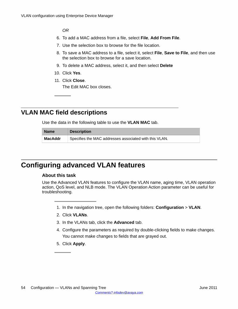
OR
6. To add a MAC address from a file, select File, Add From File.
7. Use the selection box to browse for the file location.
8. To save a MAC address to a file, select it, select File, Save to File, and then usethe selection box to browse for a save location.
9. To delete a MAC address, select it, and then select Delete
10. Click Yes.
11. Click Close.The Edit MAC box closes.
VLAN MAC field descriptionsUse the data in the following table to use the VLAN MAC tab.
Name Description
MacAddr Specifies the MAC addresses associated with this VLAN.
Configuring advanced VLAN featuresAbout this taskUse the Advanced VLAN features to configure the VLAN name, aging time, VLAN operationaction, QoS level, and NLB mode. The VLAN Operation Action parameter can be useful fortroubleshooting.
1. In the navigation tree, open the following folders: Configuration > VLAN.
2. Click VLANs.
3. In the VLANs tab, click the Advanced tab.
4. Configure the parameters as required by double-clicking fields to make changes.You cannot make changes to fields that are grayed out.
5. Click Apply.
VLAN configuration using Enterprise Device Manager
54 Configuration — VLANs and Spanning Tree June 2011Comments? [email protected]
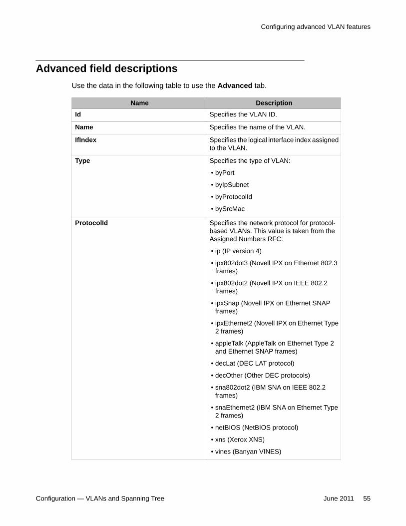
Advanced field descriptionsUse the data in the following table to use the Advanced tab.
Name DescriptionId Specifies the VLAN ID.
Name Specifies the name of the VLAN.
IfIndex Specifies the logical interface index assignedto the VLAN.
Type Specifies the type of VLAN:
• byPort
• byIpSubnet
• byProtocolId
• bySrcMac
ProtocolId Specifies the network protocol for protocol-based VLANs. This value is taken from theAssigned Numbers RFC:
• ip (IP version 4)
• ipx802dot3 (Novell IPX on Ethernet 802.3frames)
• ipx802dot2 (Novell IPX on IEEE 802.2frames)
• ipxSnap (Novell IPX on Ethernet SNAPframes)
• ipxEthernet2 (Novell IPX on Ethernet Type2 frames)
• appleTalk (AppleTalk on Ethernet Type 2and Ethernet SNAP frames)
• decLat (DEC LAT protocol)
• decOther (Other DEC protocols)
• sna802dot2 (IBM SNA on IEEE 802.2frames)
• snaEthernet2 (IBM SNA on Ethernet Type2 frames)
• netBIOS (NetBIOS protocol)
• xns (Xerox XNS)
• vines (Banyan VINES)
Configuring advanced VLAN features
Configuration — VLANs and Spanning Tree June 2011 55
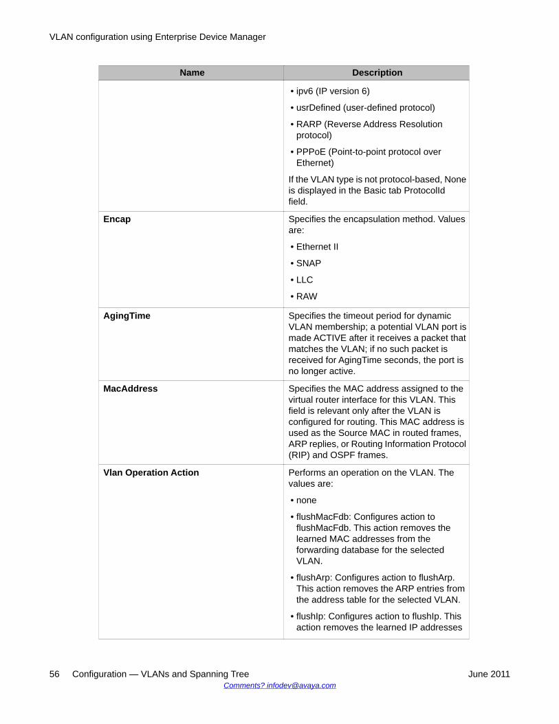
Name Description
• ipv6 (IP version 6)
• usrDefined (user-defined protocol)
• RARP (Reverse Address Resolutionprotocol)
• PPPoE (Point-to-point protocol overEthernet)
If the VLAN type is not protocol-based, Noneis displayed in the Basic tab ProtocolIdfield.
Encap Specifies the encapsulation method. Valuesare:
• Ethernet II
• SNAP
• LLC
• RAW
AgingTime Specifies the timeout period for dynamicVLAN membership; a potential VLAN port ismade ACTIVE after it receives a packet thatmatches the VLAN; if no such packet isreceived for AgingTime seconds, the port isno longer active.
MacAddress Specifies the MAC address assigned to thevirtual router interface for this VLAN. Thisfield is relevant only after the VLAN isconfigured for routing. This MAC address isused as the Source MAC in routed frames,ARP replies, or Routing Information Protocol(RIP) and OSPF frames.
Vlan Operation Action Performs an operation on the VLAN. Thevalues are:
• none
• flushMacFdb: Configures action toflushMacFdb. This action removes thelearned MAC addresses from theforwarding database for the selectedVLAN.
• flushArp: Configures action to flushArp.This action removes the ARP entries fromthe address table for the selected VLAN.
• flushIp: Configures action to flushIp. Thisaction removes the learned IP addresses
VLAN configuration using Enterprise Device Manager
56 Configuration — VLANs and Spanning Tree June 2011Comments? [email protected]
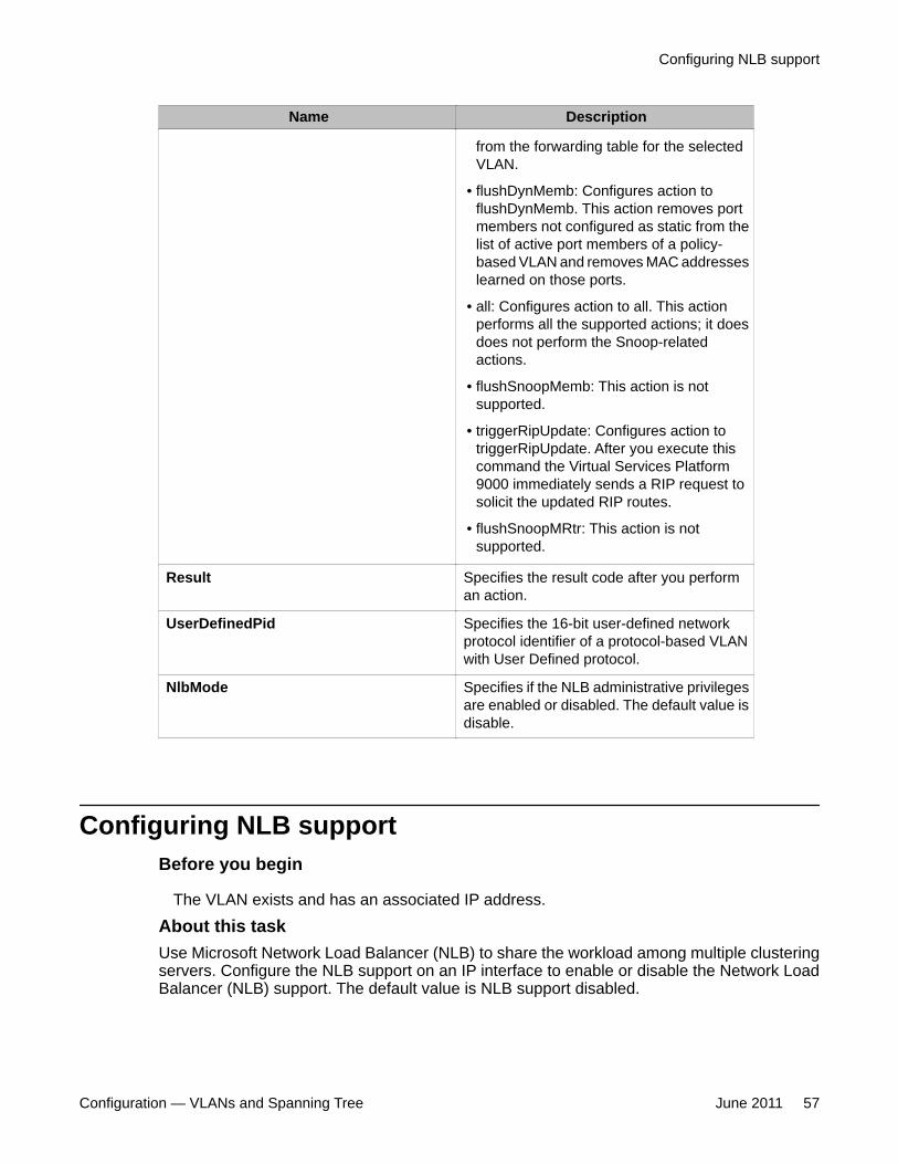
Name Description
from the forwarding table for the selectedVLAN.
• flushDynMemb: Configures action toflushDynMemb. This action removes portmembers not configured as static from thelist of active port members of a policy-based VLAN and removes MAC addresseslearned on those ports.
• all: Configures action to all. This actionperforms all the supported actions; it doesdoes not perform the Snoop-relatedactions.
• flushSnoopMemb: This action is notsupported.
• triggerRipUpdate: Configures action totriggerRipUpdate. After you execute thiscommand the Virtual Services Platform9000 immediately sends a RIP request tosolicit the updated RIP routes.
• flushSnoopMRtr: This action is notsupported.
Result Specifies the result code after you performan action.
UserDefinedPid Specifies the 16-bit user-defined networkprotocol identifier of a protocol-based VLANwith User Defined protocol.
NlbMode Specifies if the NLB administrative privilegesare enabled or disabled. The default value isdisable.
Configuring NLB supportBefore you begin
The VLAN exists and has an associated IP address.
About this taskUse Microsoft Network Load Balancer (NLB) to share the workload among multiple clusteringservers. Configure the NLB support on an IP interface to enable or disable the Network LoadBalancer (NLB) support. The default value is NLB support disabled.
Configuring NLB support
Configuration — VLANs and Spanning Tree June 2011 57
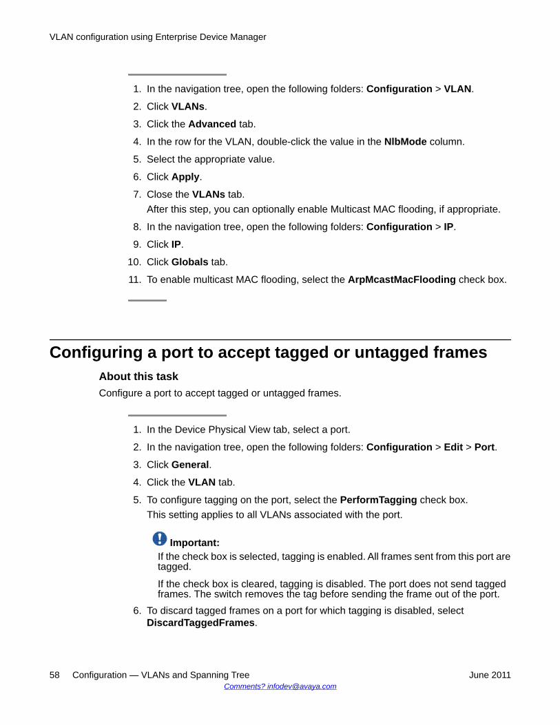
1. In the navigation tree, open the following folders: Configuration > VLAN.
2. Click VLANs.
3. Click the Advanced tab.
4. In the row for the VLAN, double-click the value in the NlbMode column.
5. Select the appropriate value.
6. Click Apply.
7. Close the VLANs tab.After this step, you can optionally enable Multicast MAC flooding, if appropriate.
8. In the navigation tree, open the following folders: Configuration > IP.
9. Click IP.
10. Click Globals tab.
11. To enable multicast MAC flooding, select the ArpMcastMacFlooding check box.
Configuring a port to accept tagged or untagged framesAbout this taskConfigure a port to accept tagged or untagged frames.
1. In the Device Physical View tab, select a port.
2. In the navigation tree, open the following folders: Configuration > Edit > Port.
3. Click General.
4. Click the VLAN tab.
5. To configure tagging on the port, select the PerformTagging check box.This setting applies to all VLANs associated with the port.
Important:If the check box is selected, tagging is enabled. All frames sent from this port aretagged.
If the check box is cleared, tagging is disabled. The port does not send taggedframes. The switch removes the tag before sending the frame out of the port.
6. To discard tagged frames on a port for which tagging is disabled, selectDiscardTaggedFrames.
VLAN configuration using Enterprise Device Manager
58 Configuration — VLANs and Spanning Tree June 2011Comments? [email protected]
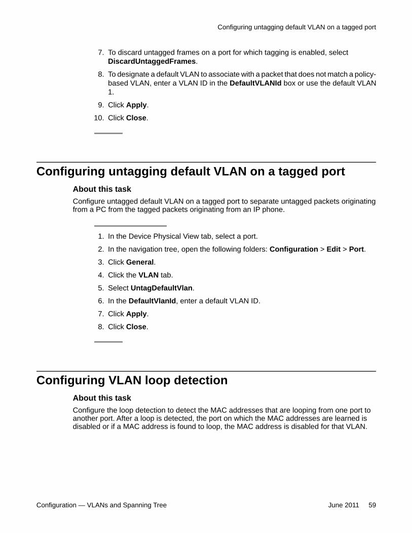
7. To discard untagged frames on a port for which tagging is enabled, selectDiscardUntaggedFrames.
8. To designate a default VLAN to associate with a packet that does not match a policy-based VLAN, enter a VLAN ID in the DefaultVLANId box or use the default VLAN1.
9. Click Apply.
10. Click Close.
Configuring untagging default VLAN on a tagged portAbout this taskConfigure untagged default VLAN on a tagged port to separate untagged packets originatingfrom a PC from the tagged packets originating from an IP phone.
1. In the Device Physical View tab, select a port.
2. In the navigation tree, open the following folders: Configuration > Edit > Port.
3. Click General.
4. Click the VLAN tab.
5. Select UntagDefaultVlan.
6. In the DefaultVlanId, enter a default VLAN ID.
7. Click Apply.
8. Click Close.
Configuring VLAN loop detectionAbout this taskConfigure the loop detection to detect the MAC addresses that are looping from one port toanother port. After a loop is detected, the port on which the MAC addresses are learned isdisabled or if a MAC address is found to loop, the MAC address is disabled for that VLAN.
Configuring untagging default VLAN on a tagged port
Configuration — VLANs and Spanning Tree June 2011 59
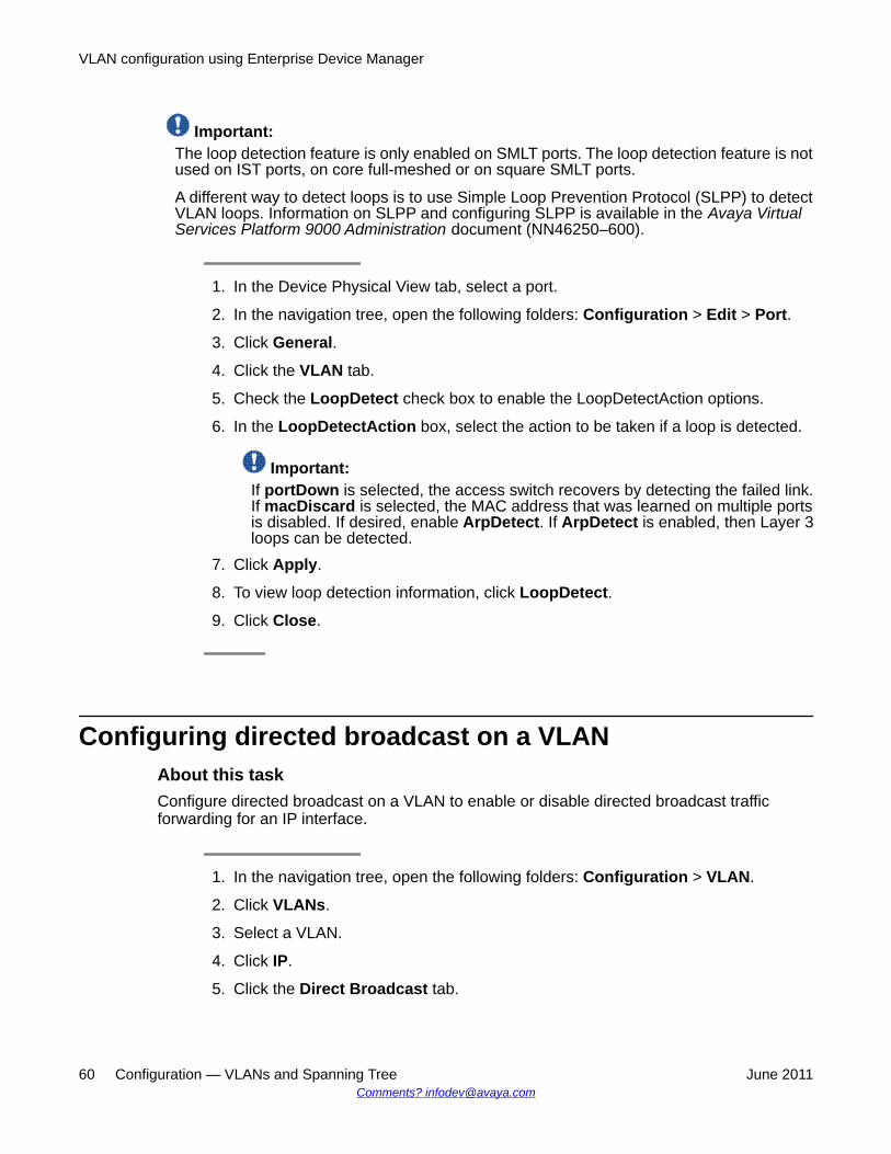
Important:The loop detection feature is only enabled on SMLT ports. The loop detection feature is notused on IST ports, on core full-meshed or on square SMLT ports.
A different way to detect loops is to use Simple Loop Prevention Protocol (SLPP) to detectVLAN loops. Information on SLPP and configuring SLPP is available in the Avaya VirtualServices Platform 9000 Administration document (NN46250–600).
1. In the Device Physical View tab, select a port.
2. In the navigation tree, open the following folders: Configuration > Edit > Port.
3. Click General.
4. Click the VLAN tab.
5. Check the LoopDetect check box to enable the LoopDetectAction options.
6. In the LoopDetectAction box, select the action to be taken if a loop is detected.
Important:If portDown is selected, the access switch recovers by detecting the failed link.If macDiscard is selected, the MAC address that was learned on multiple portsis disabled. If desired, enable ArpDetect. If ArpDetect is enabled, then Layer 3loops can be detected.
7. Click Apply.
8. To view loop detection information, click LoopDetect.
9. Click Close.
Configuring directed broadcast on a VLANAbout this taskConfigure directed broadcast on a VLAN to enable or disable directed broadcast trafficforwarding for an IP interface.
1. In the navigation tree, open the following folders: Configuration > VLAN.
2. Click VLANs.
3. Select a VLAN.
4. Click IP.
5. Click the Direct Broadcast tab.
VLAN configuration using Enterprise Device Manager
60 Configuration — VLANs and Spanning Tree June 2011Comments? [email protected]
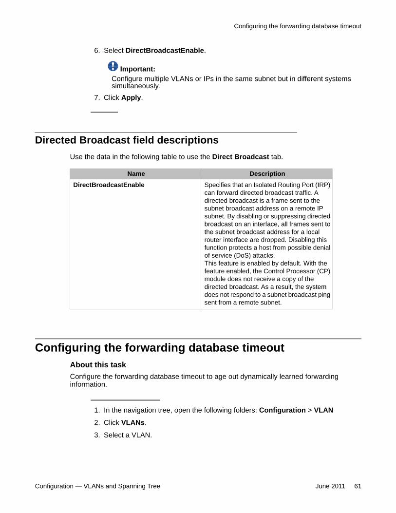
6. Select DirectBroadcastEnable.
Important:Configure multiple VLANs or IPs in the same subnet but in different systemssimultaneously.
7. Click Apply.
Directed Broadcast field descriptionsUse the data in the following table to use the Direct Broadcast tab.
Name DescriptionDirectBroadcastEnable Specifies that an Isolated Routing Port (IRP)
can forward directed broadcast traffic. Adirected broadcast is a frame sent to thesubnet broadcast address on a remote IPsubnet. By disabling or suppressing directedbroadcast on an interface, all frames sent tothe subnet broadcast address for a localrouter interface are dropped. Disabling thisfunction protects a host from possible denialof service (DoS) attacks.This feature is enabled by default. With thefeature enabled, the Control Processor (CP)module does not receive a copy of thedirected broadcast. As a result, the systemdoes not respond to a subnet broadcast pingsent from a remote subnet.
Configuring the forwarding database timeoutAbout this taskConfigure the forwarding database timeout to age out dynamically learned forwardinginformation.
1. In the navigation tree, open the following folders: Configuration > VLAN
2. Click VLANs.
3. Select a VLAN.
Configuring the forwarding database timeout
Configuration — VLANs and Spanning Tree June 2011 61
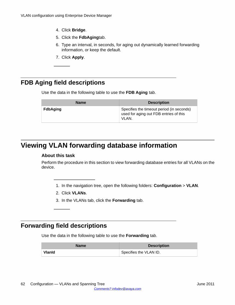
4. Click Bridge.
5. Click the FdbAgingtab.
6. Type an interval, in seconds, for aging out dynamically learned forwardinginformation, or keep the default.
7. Click Apply.
FDB Aging field descriptionsUse the data in the following table to use the FDB Aging tab.
Name DescriptionFdbAging Specifies the timeout period (in seconds)
used for aging out FDB entries of thisVLAN.
Viewing VLAN forwarding database informationAbout this taskPerform the procedure in this section to view forwarding database entries for all VLANs on thedevice.
1. In the navigation tree, open the following folders: Configuration > VLAN.
2. Click VLANs.
3. In the VLANs tab, click the Forwarding tab.
Forwarding field descriptionsUse the data in the following table to use the Forwarding tab.
Name DescriptionVlanId Specifies the VLAN ID.
VLAN configuration using Enterprise Device Manager
62 Configuration — VLANs and Spanning Tree June 2011Comments? [email protected]
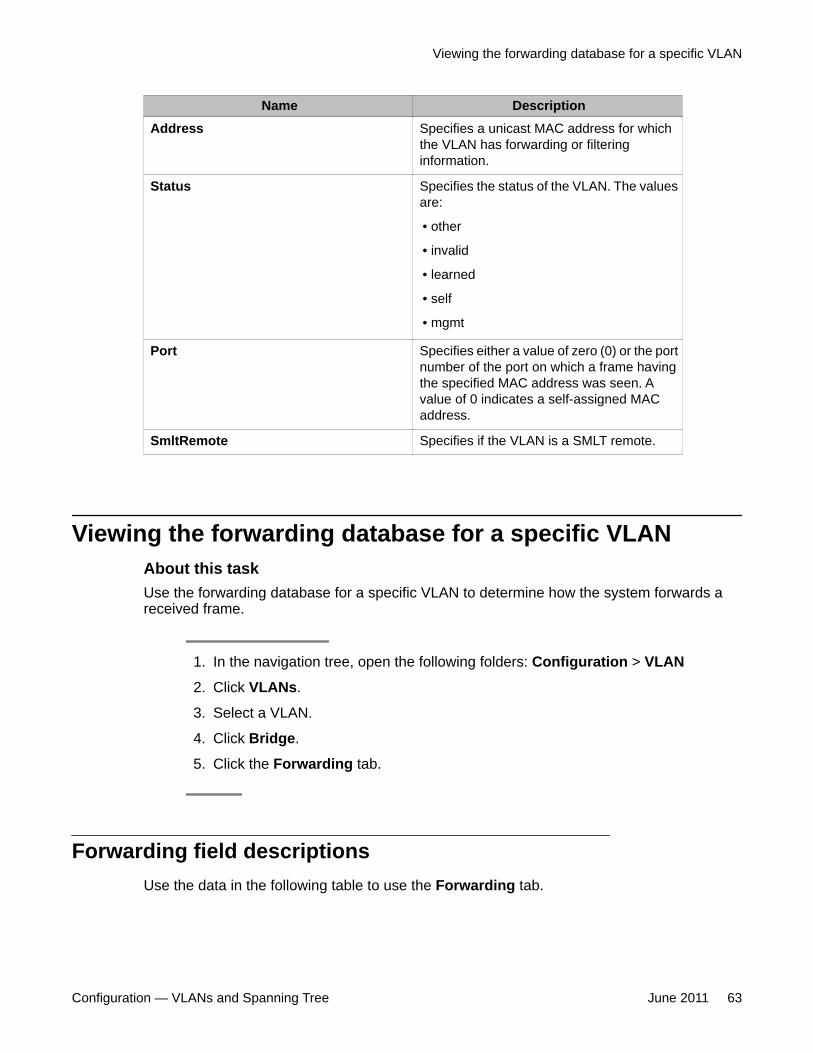
Name DescriptionAddress Specifies a unicast MAC address for which
the VLAN has forwarding or filteringinformation.
Status Specifies the status of the VLAN. The valuesare:
• other
• invalid
• learned
• self
• mgmt
Port Specifies either a value of zero (0) or the portnumber of the port on which a frame havingthe specified MAC address was seen. Avalue of 0 indicates a self-assigned MACaddress.
SmltRemote Specifies if the VLAN is a SMLT remote.
Viewing the forwarding database for a specific VLANAbout this taskUse the forwarding database for a specific VLAN to determine how the system forwards areceived frame.
1. In the navigation tree, open the following folders: Configuration > VLAN
2. Click VLANs.
3. Select a VLAN.
4. Click Bridge.
5. Click the Forwarding tab.
Forwarding field descriptionsUse the data in the following table to use the Forwarding tab.
Viewing the forwarding database for a specific VLAN
Configuration — VLANs and Spanning Tree June 2011 63
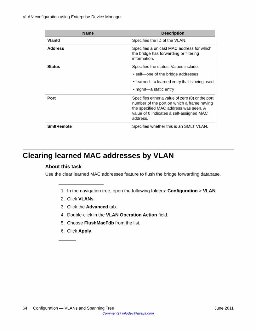
Name DescriptionVlanId Specifies the ID of the VLAN.
Address Specifies a unicast MAC address for whichthe bridge has forwarding or filteringinformation.
Status Specifies the status. Values include:
• self—one of the bridge addresses
• learned—a learned entry that is being used
• mgmt—a static entry
Port Specifies either a value of zero (0) or the portnumber of the port on which a frame havingthe specified MAC address was seen. Avalue of 0 indicates a self-assigned MACaddress.
SmltRemote Specifies whether this is an SMLT VLAN.
Clearing learned MAC addresses by VLANAbout this taskUse the clear learned MAC addresses feature to flush the bridge forwarding database.
1. In the navigation tree, open the following folders: Configuration > VLAN.
2. Click VLANs.
3. Click the Advanced tab.
4. Double-click in the VLAN Operation Action field.
5. Choose FlushMacFdb from the list.
6. Click Apply.
VLAN configuration using Enterprise Device Manager
64 Configuration — VLANs and Spanning Tree June 2011Comments? [email protected]
Clearing learned MAC addresses for all VLANs by portAbout this taskClear learned MAC addresses for all VLANs by port to clear all the forwarding database (FDB)for VLANs associated with this port.
1. In the Device Physical View tab, select a port.
2. In the navigation tree, open the following folders: Configuration > Edit > Port.
3. Click General.
4. In the Interface tab Action box, select FlushMacFdb.
5. Click Apply.All learned MAC addresses are cleared from the forwarding database (FDB) forVLANs associated with this port.
6. Click Close.
Configuring static forwardingAbout this taskConfigure static forwarding to specify the group of ports that are allowed to forward frames.
Important:Entries are valid for unicast and for group/broadcast addresses.
1. In the navigation tree, open the following folders: Configuration > VLAN.
2. Click VLANs.
3. Select a VLAN.
4. Click Bridge.
5. In the Bridge, VLAN tab, click the Static tab.
6. Click Insert.
7. In the MacAddress box, enter a forwarding destination MAC address.
8. In the Port box, click the ellipsis button (...).
Clearing learned MAC addresses for all VLANs by port
Configuration — VLANs and Spanning Tree June 2011 65
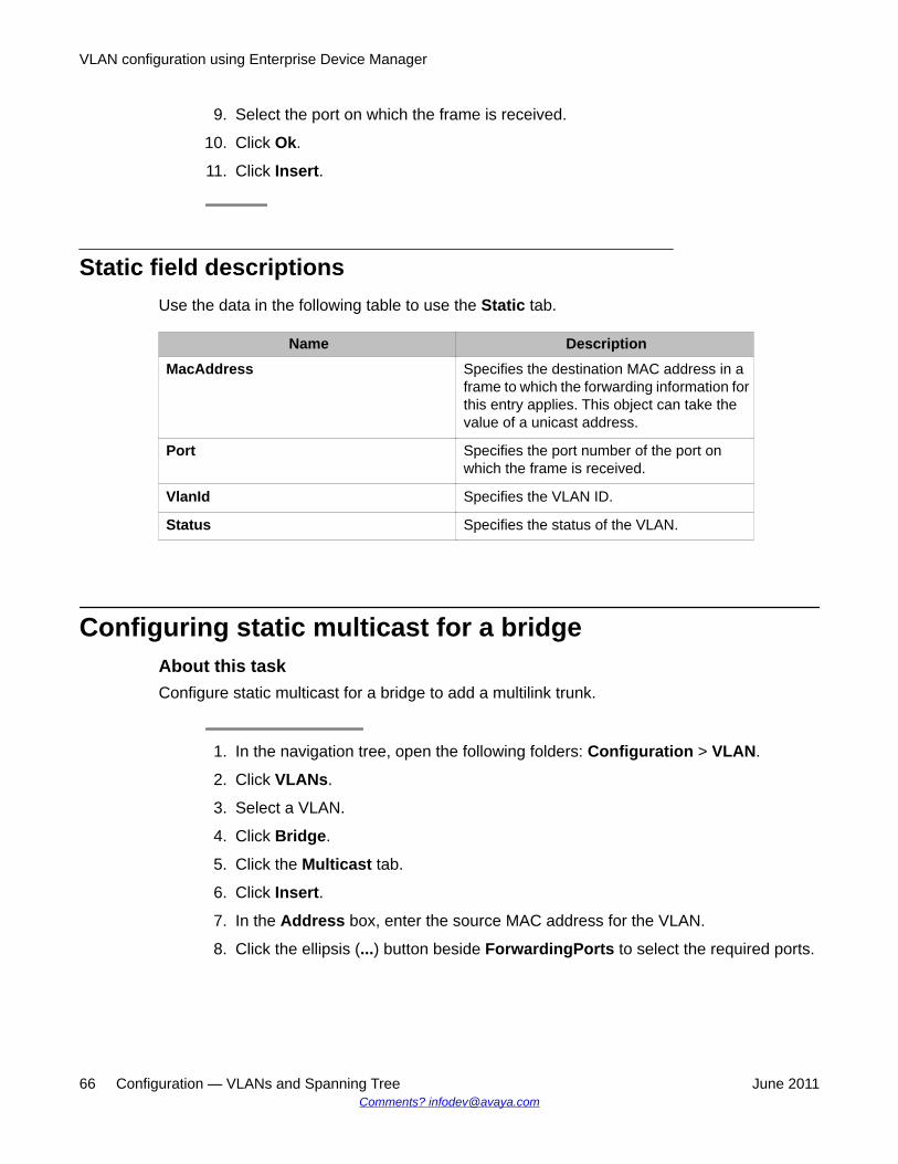
9. Select the port on which the frame is received.
10. Click Ok.
11. Click Insert.
Static field descriptionsUse the data in the following table to use the Static tab.
Name DescriptionMacAddress Specifies the destination MAC address in a
frame to which the forwarding information forthis entry applies. This object can take thevalue of a unicast address.
Port Specifies the port number of the port onwhich the frame is received.
VlanId Specifies the VLAN ID.
Status Specifies the status of the VLAN.
Configuring static multicast for a bridgeAbout this taskConfigure static multicast for a bridge to add a multilink trunk.
1. In the navigation tree, open the following folders: Configuration > VLAN.
2. Click VLANs.
3. Select a VLAN.
4. Click Bridge.
5. Click the Multicast tab.
6. Click Insert.
7. In the Address box, enter the source MAC address for the VLAN.
8. Click the ellipsis (...) button beside ForwardingPorts to select the required ports.
VLAN configuration using Enterprise Device Manager
66 Configuration — VLANs and Spanning Tree June 2011Comments? [email protected]
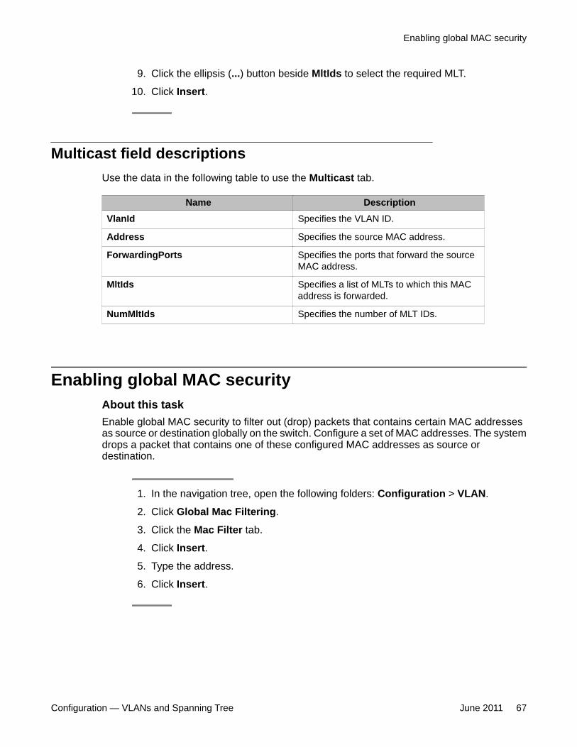
9. Click the ellipsis (...) button beside MltIds to select the required MLT.
10. Click Insert.
Multicast field descriptionsUse the data in the following table to use the Multicast tab.
Name DescriptionVlanId Specifies the VLAN ID.
Address Specifies the source MAC address.
ForwardingPorts Specifies the ports that forward the sourceMAC address.
MltIds Specifies a list of MLTs to which this MACaddress is forwarded.
NumMltIds Specifies the number of MLT IDs.
Enabling global MAC securityAbout this taskEnable global MAC security to filter out (drop) packets that contains certain MAC addressesas source or destination globally on the switch. Configure a set of MAC addresses. The systemdrops a packet that contains one of these configured MAC addresses as source ordestination.
1. In the navigation tree, open the following folders: Configuration > VLAN.
2. Click Global Mac Filtering.
3. Click the Mac Filter tab.
4. Click Insert.
5. Type the address.
6. Click Insert.
Enabling global MAC security
Configuration — VLANs and Spanning Tree June 2011 67
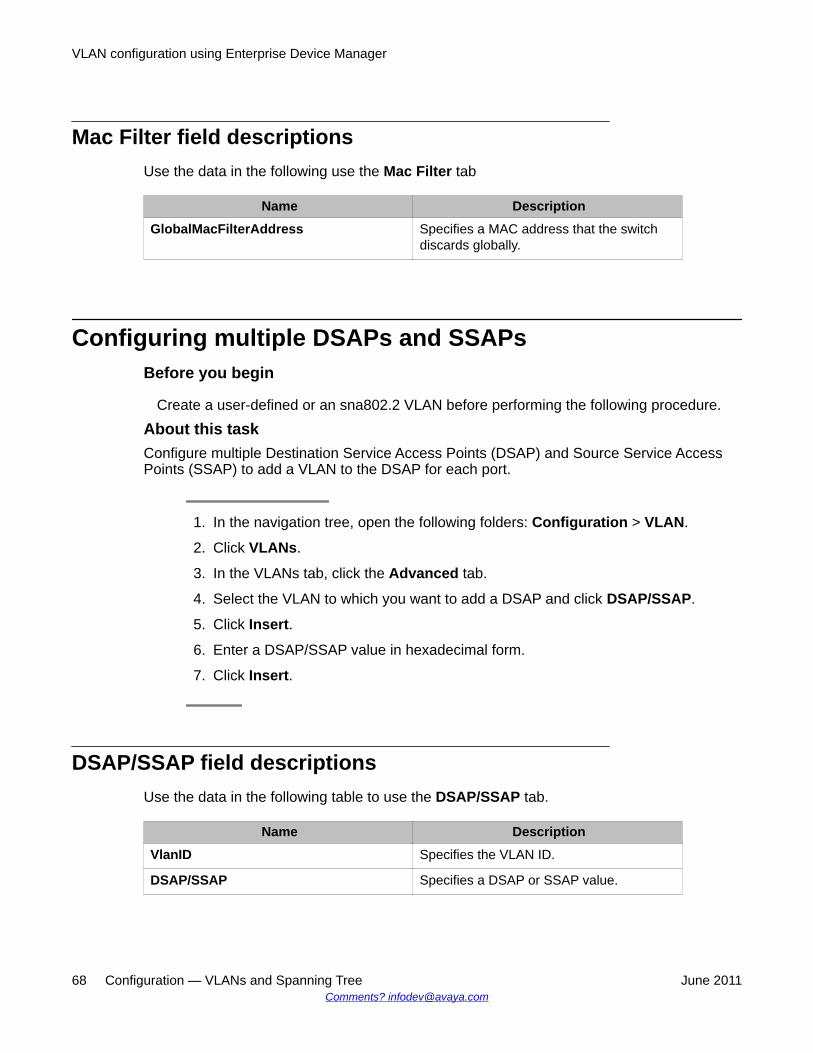
Mac Filter field descriptionsUse the data in the following use the Mac Filter tab
Name DescriptionGlobalMacFilterAddress Specifies a MAC address that the switch
discards globally.
Configuring multiple DSAPs and SSAPsBefore you begin
Create a user-defined or an sna802.2 VLAN before performing the following procedure.
About this taskConfigure multiple Destination Service Access Points (DSAP) and Source Service AccessPoints (SSAP) to add a VLAN to the DSAP for each port.
1. In the navigation tree, open the following folders: Configuration > VLAN.
2. Click VLANs.
3. In the VLANs tab, click the Advanced tab.
4. Select the VLAN to which you want to add a DSAP and click DSAP/SSAP.
5. Click Insert.
6. Enter a DSAP/SSAP value in hexadecimal form.
7. Click Insert.
DSAP/SSAP field descriptionsUse the data in the following table to use the DSAP/SSAP tab.
Name DescriptionVlanID Specifies the VLAN ID.
DSAP/SSAP Specifies a DSAP or SSAP value.
VLAN configuration using Enterprise Device Manager
68 Configuration — VLANs and Spanning Tree June 2011Comments? [email protected]
Enabling unknown MAC discardAbout this taskAfter you configure a port with UnknownMacDiscard enabled, the port drops packets withunknown source MAC addresses.
1. In the Device Physical View tab, select a port or multiple ports.
2. In the navigation tree, open the following folders: Configuration > Edit > Port.
3. Click General.
4. Click the Interface tab.
5. Select UnknownMacDiscard.
6. Click Apply.
Configuring MAC learning parametersBefore you begin
To use MAC learning features, you must enable UnknownMacDiscard on the port.
About this taskConfigure MAC learning parameters to control high-security environments that restrict accessto the network. This feature is based on the Layer 2 MAC address of the network devicesconnected to the Avaya Virtual Services Platform 9000.
After you configure a port with UnknownMacDiscard enabled, the port drops packets withunknown source MAC addresses. Use the autolearning feature to configure the number ofunknown MAC addresses to learn on a port. Use the allow MAC learning feature to permitforwarding of packets from specific source MAC addresses for specific ports.
Configure autolearning so the system processes packets with an unknown MAC address. Youconfigure the number of address the system learns by configuring a maximum number ofaddresses.
1. In the Device Physical View tab, select a port or multiple ports.
2. In the navigation tree, open the following folders: Configuration > Edit > Port.
3. Click General.
Enabling unknown MAC discard
Configuration — VLANs and Spanning Tree June 2011 69
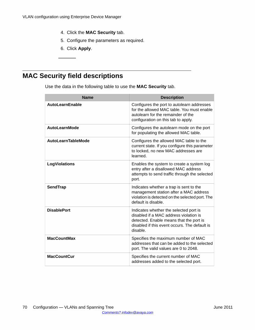
4. Click the MAC Security tab.
5. Configure the parameters as required.
6. Click Apply.
MAC Security field descriptionsUse the data in the following table to use the MAC Security tab.
Name DescriptionAutoLearnEnable Configures the port to autolearn addresses
for the allowed MAC table. You must enableautolearn for the remainder of theconfiguration on this tab to apply.
AutoLearnMode Configures the autolearn mode on the portfor populating the allowed MAC table.
AutoLearnTableMode Configures the allowed MAC table to thecurrent state. If you configure this parameterto locked, no new MAC addresses arelearned.
LogViolations Enables the system to create a system logentry after a disallowed MAC addressattempts to send traffic through the selectedport.
SendTrap Indicates whether a trap is sent to themanagement station after a MAC addressviolation is detected on the selected port. Thedefault is disable.
DisablePort Indicates whether the selected port isdisabled if a MAC address violation isdetected. Enable means that the port isdisabled if this event occurs. The default isdisable.
MacCountMax Specifies the maximum number of MACaddresses that can be added to the selectedport. The valid values are 0 to 2048.
MacCountCur Specifies the current number of MACaddresses added to the selected port.
VLAN configuration using Enterprise Device Manager
70 Configuration — VLANs and Spanning Tree June 2011Comments? [email protected]
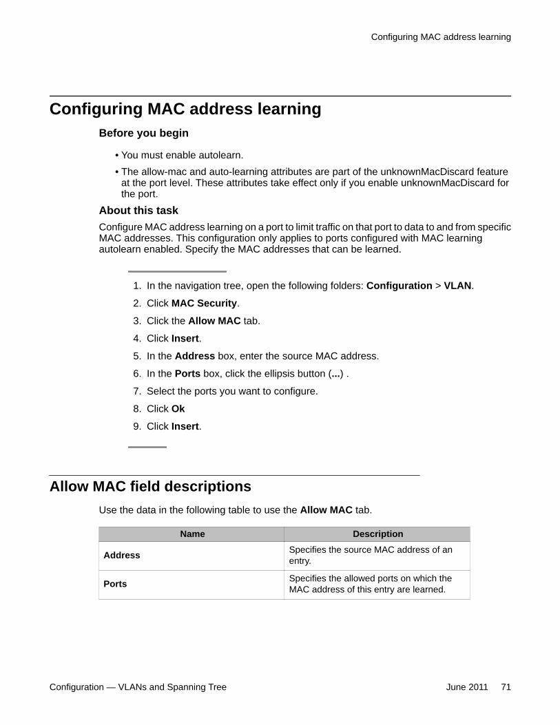
Configuring MAC address learningBefore you begin
• You must enable autolearn.• The allow-mac and auto-learning attributes are part of the unknownMacDiscard feature
at the port level. These attributes take effect only if you enable unknownMacDiscard forthe port.
About this taskConfigure MAC address learning on a port to limit traffic on that port to data to and from specificMAC addresses. This configuration only applies to ports configured with MAC learningautolearn enabled. Specify the MAC addresses that can be learned.
1. In the navigation tree, open the following folders: Configuration > VLAN.
2. Click MAC Security.
3. Click the Allow MAC tab.
4. Click Insert.
5. In the Address box, enter the source MAC address.
6. In the Ports box, click the ellipsis button (...) .
7. Select the ports you want to configure.
8. Click Ok
9. Click Insert.
Allow MAC field descriptionsUse the data in the following table to use the Allow MAC tab.
Name Description
Address Specifies the source MAC address of anentry.
Ports Specifies the allowed ports on which theMAC address of this entry are learned.
Configuring MAC address learning
Configuration — VLANs and Spanning Tree June 2011 71
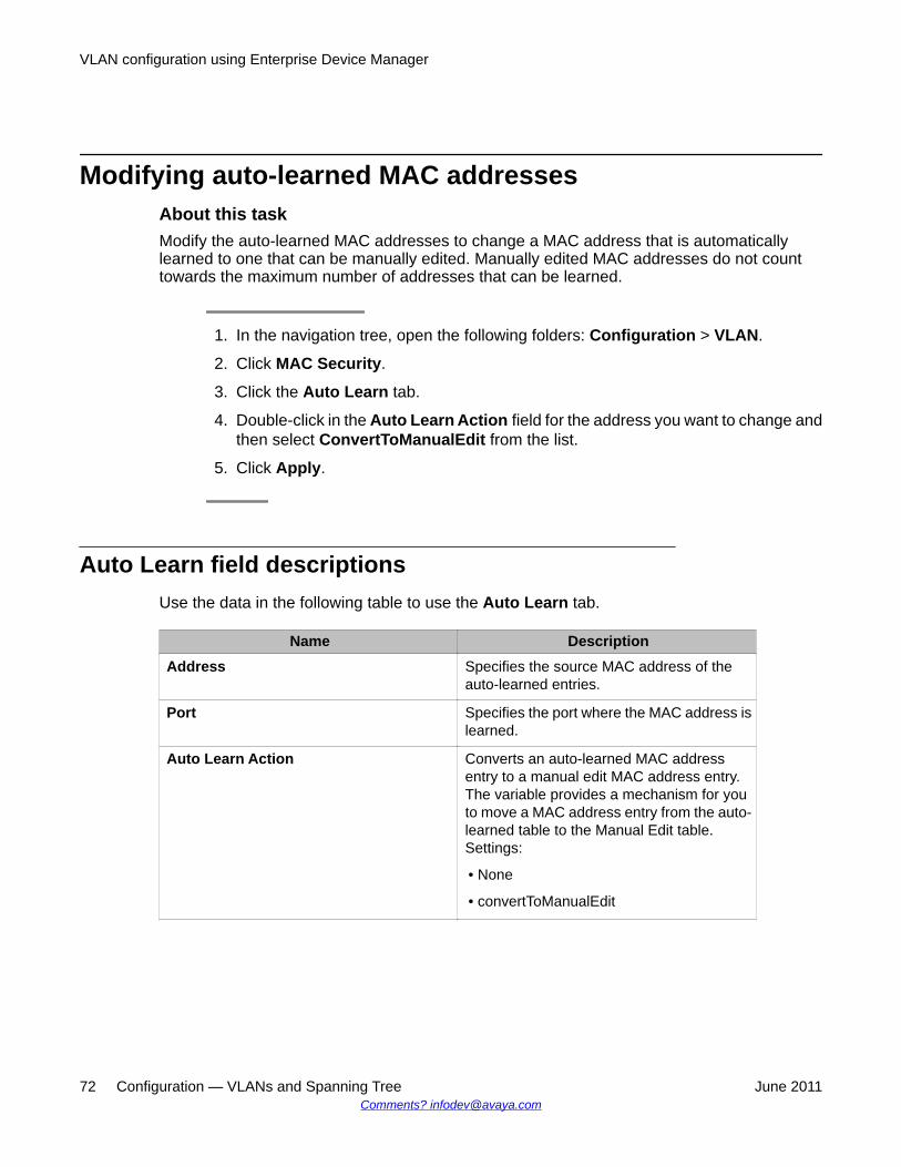
Modifying auto-learned MAC addressesAbout this taskModify the auto-learned MAC addresses to change a MAC address that is automaticallylearned to one that can be manually edited. Manually edited MAC addresses do not counttowards the maximum number of addresses that can be learned.
1. In the navigation tree, open the following folders: Configuration > VLAN.
2. Click MAC Security.
3. Click the Auto Learn tab.
4. Double-click in the Auto Learn Action field for the address you want to change andthen select ConvertToManualEdit from the list.
5. Click Apply.
Auto Learn field descriptionsUse the data in the following table to use the Auto Learn tab.
Name DescriptionAddress Specifies the source MAC address of the
auto-learned entries.
Port Specifies the port where the MAC address islearned.
Auto Learn Action Converts an auto-learned MAC addressentry to a manual edit MAC address entry.The variable provides a mechanism for youto move a MAC address entry from the auto-learned table to the Manual Edit table.Settings:
• None
• convertToManualEdit
VLAN configuration using Enterprise Device Manager
72 Configuration — VLANs and Spanning Tree June 2011Comments? [email protected]
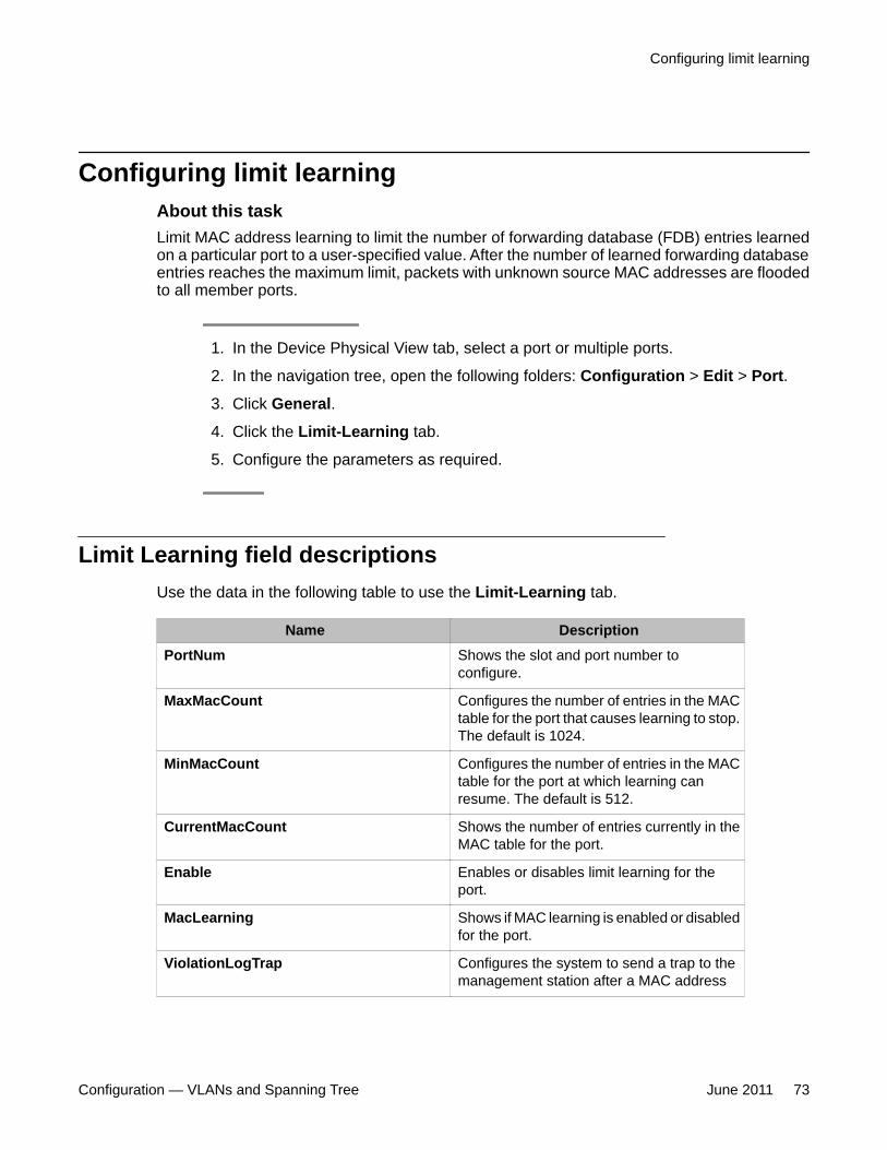
Configuring limit learningAbout this taskLimit MAC address learning to limit the number of forwarding database (FDB) entries learnedon a particular port to a user-specified value. After the number of learned forwarding databaseentries reaches the maximum limit, packets with unknown source MAC addresses are floodedto all member ports.
1. In the Device Physical View tab, select a port or multiple ports.
2. In the navigation tree, open the following folders: Configuration > Edit > Port.
3. Click General.
4. Click the Limit-Learning tab.
5. Configure the parameters as required.
Limit Learning field descriptionsUse the data in the following table to use the Limit-Learning tab.
Name DescriptionPortNum Shows the slot and port number to
configure.
MaxMacCount Configures the number of entries in the MACtable for the port that causes learning to stop.The default is 1024.
MinMacCount Configures the number of entries in the MACtable for the port at which learning canresume. The default is 512.
CurrentMacCount Shows the number of entries currently in theMAC table for the port.
Enable Enables or disables limit learning for theport.
MacLearning Shows if MAC learning is enabled or disabledfor the port.
ViolationLogTrap Configures the system to send a trap to themanagement station after a MAC address
Configuring limit learning
Configuration — VLANs and Spanning Tree June 2011 73
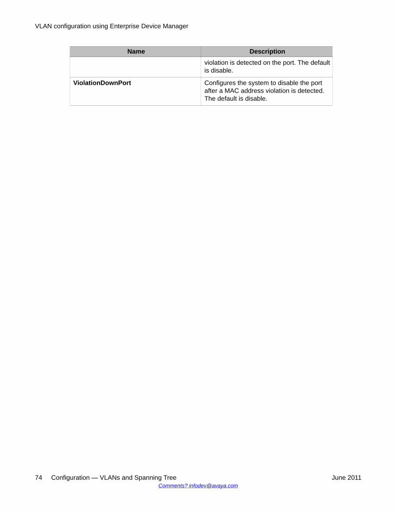
Name Descriptionviolation is detected on the port. The defaultis disable.
ViolationDownPort Configures the system to disable the portafter a MAC address violation is detected.The default is disable.
VLAN configuration using Enterprise Device Manager
74 Configuration — VLANs and Spanning Tree June 2011Comments? [email protected]
Chapter 6: VLAN configuration using ACLI
This chapter describes how to configure and manage a virtual local area network (VLAN) by using theAvaya Command Line Interface (ACLI).
Configure and manage a VLAN to create VLANs, add or remove ports in the VLAN, configure priority,change a VLAN name, or perform other operations.
Important:You can also configure loop detection and other features.
• Creating a VLAN on page 76
• Assigning an IP address to a VLAN on page 78
• Performing a general VLAN action on page 79
• Configuring static MAC addresses for a VLAN on page 80
• Enabling global MAC security on page 81
• Limiting MAC address learning on page 82
• Configuring autolearning and allowed MAC addresses on page 83
• Adding or removing ports in a VLAN on page 85
• Adding or removing source MAC addresses for a VLAN on page 86
• Configuring VLAN classification precedence on page 87
• Configuring NLB support on page 88
• Configuring a tagged port to discard untagged frames on page 89
• Configuring VLAN loop detection on page 90
• Configuring spoof detection on page 91
• Configuring multiple DSAP and SSAP on page 92
• Viewing VLAN information on page 93
• Viewing brouter port information on page 94
• Viewing VLAN port member status on page 94
• Viewing VLAN source MAC addresses on page 95
• Viewing VLAN forwarding database information on page 96
• Viewing manual edit MAC addresses on page 97
• Viewing multicast MAC addresses on page 97
Configuration — VLANs and Spanning Tree June 2011 75
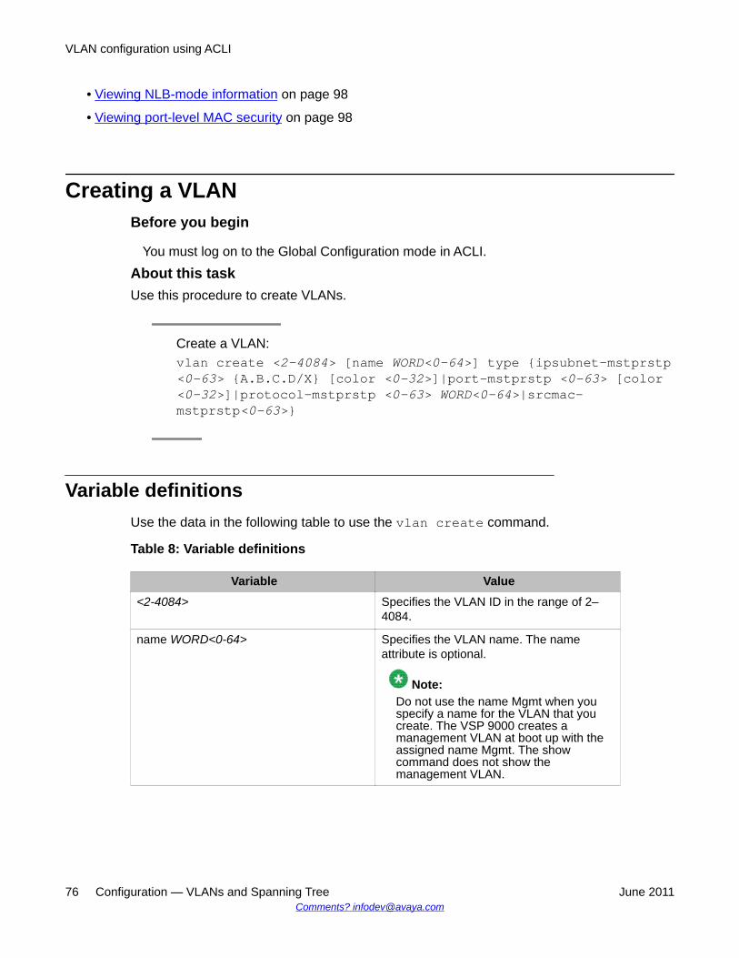
• Viewing NLB-mode information on page 98
• Viewing port-level MAC security on page 98
Creating a VLANBefore you begin
You must log on to the Global Configuration mode in ACLI.
About this taskUse this procedure to create VLANs.
Create a VLAN:vlan create <2-4084> [name WORD<0-64>] type {ipsubnet-mstprstp<0-63> {A.B.C.D/X} [color <0-32>]|port-mstprstp <0-63> [color<0-32>]|protocol-mstprstp <0-63> WORD<0-64>|srcmac-mstprstp<0-63>}
Variable definitionsUse the data in the following table to use the vlan create command.
Table 8: Variable definitions
Variable Value<2-4084> Specifies the VLAN ID in the range of 2–
4084.
name WORD<0-64> Specifies the VLAN name. The nameattribute is optional.
Note:Do not use the name Mgmt when youspecify a name for the VLAN that youcreate. The VSP 9000 creates amanagement VLAN at boot up with theassigned name Mgmt. The showcommand does not show themanagement VLAN.
VLAN configuration using ACLI
76 Configuration — VLANs and Spanning Tree June 2011Comments? [email protected]
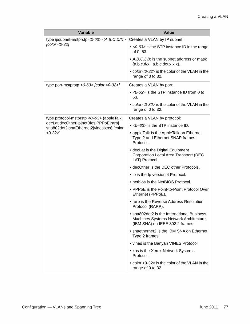
Variable Valuetype ipsubnet-mstprstp <0-63> <A.B.C.D/X>[color <0-32]
Creates a VLAN by IP subnet:
• <0-63> is the STP instance ID in the rangeof 0–63.
• A.B.C.D/X is the subnet address or mask{a.b.c.d/x | a.b.c.d/x.x.x.x}.
• color <0-32> is the color of the VLAN in therange of 0 to 32.
type port-mstprstp <0-63> [color <0-32>] Creates a VLAN by port:
• <0-63> is the STP instance ID from 0 to63.
• color <0-32> is the color of the VLAN in therange of 0 to 32.
type protocol-mstprstp <0–63> {appleTalk|decLat|decOther|ip|netBios|PPPoE|rarp|sna802dot2|snaEthernet2|vines|xns} [color<0-32>]
Creates a VLAN by protocol:
• <0–63> is the STP instance ID.
• appleTalk is the AppleTalk on EthernetType 2 and Ethernet SNAP framesProtocol.
• decLat is the Digital EquipmentCorporation Local Area Transport (DECLAT) Protocol.
• decOther is the DEC other Protocols.
• ip is the Ip version 4 Protocol.
• netbios is the NetBIOS Protocol.
• PPPoE is the Point-to-Point Protocol OverEthernet (PPPoE).
• rarp is the Reverse Address ResolutionProtocol (RARP).
• sna802dot2 is the International BusinessMachines Systems Network Architecture(IBM SNA) on IEEE 802.2 frames.
• snaethernet2 is the IBM SNA on EthernetType 2 frames.
• vines is the Banyan VINES Protocol.
• xns is the Xerox Network SystemsProtocol.
• color <0-32> is the color of the VLAN in therange of 0 to 32.
Creating a VLAN
Configuration — VLANs and Spanning Tree June 2011 77
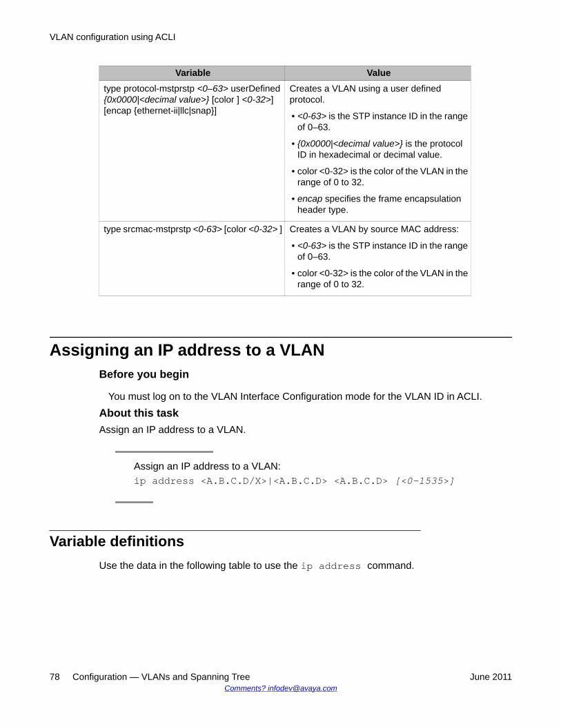
Variable Valuetype protocol-mstprstp <0–63> userDefined{0x0000|<decimal value>} [color ] <0-32>][encap {ethernet-ii|llc|snap}]
Creates a VLAN using a user definedprotocol.
• <0-63> is the STP instance ID in the rangeof 0–63.
• {0x0000|<decimal value>} is the protocolID in hexadecimal or decimal value.
• color <0-32> is the color of the VLAN in therange of 0 to 32.
• encap specifies the frame encapsulationheader type.
type srcmac-mstprstp <0-63> [color <0-32> ] Creates a VLAN by source MAC address:
• <0-63> is the STP instance ID in the rangeof 0–63.
• color <0-32> is the color of the VLAN in therange of 0 to 32.
Assigning an IP address to a VLANBefore you begin
You must log on to the VLAN Interface Configuration mode for the VLAN ID in ACLI.
About this taskAssign an IP address to a VLAN.
Assign an IP address to a VLAN:ip address <A.B.C.D/X>|<A.B.C.D> <A.B.C.D> [<0-1535>]
Variable definitionsUse the data in the following table to use the ip address command.
VLAN configuration using ACLI
78 Configuration — VLANs and Spanning Tree June 2011Comments? [email protected]
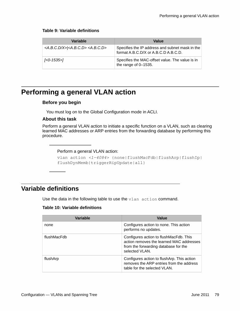
Table 9: Variable definitions
Variable Value<A.B.C.D/X>|<A.B.C.D> <A.B.C.D> Specifies the IP address and subnet mask in the
format A.B.C.D/X or A.B.C.D A.B.C.D.
[<0-1535>] Specifies the MAC-offset value. The value is inthe range of 0–1535.
Performing a general VLAN actionBefore you begin
You must log on to the Global Configuration mode in ACLI.
About this taskPerform a general VLAN action to initiate a specific function on a VLAN, such as clearinglearned MAC addresses or ARP entries from the forwarding database by performing thisprocedure.
Perform a general VLAN action:vlan action <1-4084> {none|flushMacFdb|flushArp|flushIp|flushDynMemb|triggerRipUpdate|all}
Variable definitionsUse the data in the following table to use the vlan action command.
Table 10: Variable definitions
Variable Valuenone Configures action to none. This action
performs no updates.
flushMacFdb Configures action to flushMacFdb. Thisaction removes the learned MAC addressesfrom the forwarding database for theselected VLAN.
flushArp Configures action to flushArp. This actionremoves the ARP entries from the addresstable for the selected VLAN.
Performing a general VLAN action
Configuration — VLANs and Spanning Tree June 2011 79
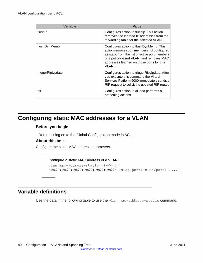
Variable ValueflushIp Configures action to flushIp. This action
removes the learned IP addresses from theforwarding table for the selected VLAN. .
flushDynMemb Configures action to flushDynMemb. Thisaction removes port members not configuredas static from the list of active port membersof a policy-based VLAN, and removes MACaddresses learned on those ports for thisVLAN.
triggerRipUpdate Configures action to triggerRipUpdate. Afteryou execute this command the VirtualServices Platform 9000 immediately sends aRIP request to solicit the updated RIP routes
all Configures action to all and performs allpreceding actions.
Configuring static MAC addresses for a VLANBefore you begin
You must log on to the Global Configuration mode in ACLI.
About this taskConfigure the static MAC address parameters.
Configure a static MAC address of a VLAN:vlan mac-address-static <1-4084><0x00:0x00:0x00:0x00:0x00:0x00> {slot/port[-slot/port][,...]}
Variable definitionsUse the data in the following table to use the vlan mac-address-static command.
VLAN configuration using ACLI
80 Configuration — VLANs and Spanning Tree June 2011Comments? [email protected]
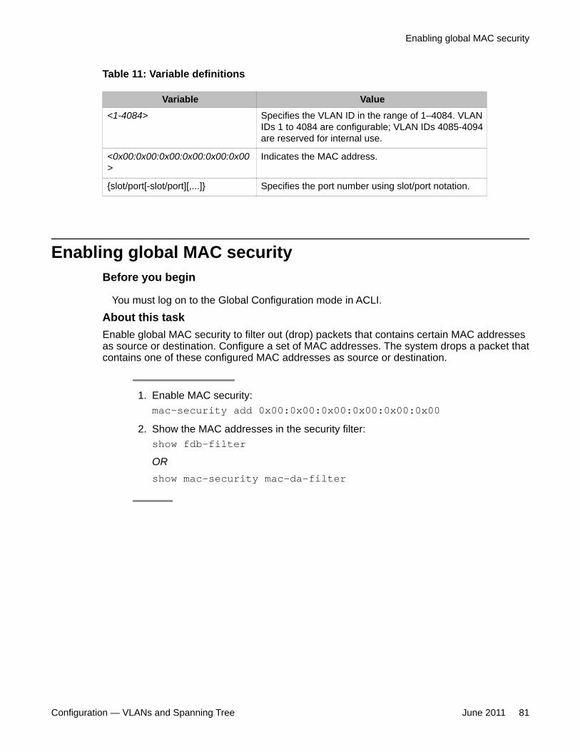
Table 11: Variable definitions
Variable Value<1-4084> Specifies the VLAN ID in the range of 1–4084. VLAN
IDs 1 to 4084 are configurable; VLAN IDs 4085-4094are reserved for internal use.
<0x00:0x00:0x00:0x00:0x00:0x00>
Indicates the MAC address.
{slot/port[-slot/port][,...]} Specifies the port number using slot/port notation.
Enabling global MAC securityBefore you begin
You must log on to the Global Configuration mode in ACLI.
About this taskEnable global MAC security to filter out (drop) packets that contains certain MAC addressesas source or destination. Configure a set of MAC addresses. The system drops a packet thatcontains one of these configured MAC addresses as source or destination.
1. Enable MAC security:mac-security add 0x00:0x00:0x00:0x00:0x00:0x00
2. Show the MAC addresses in the security filter:show fdb-filterORshow mac-security mac-da-filter
Enabling global MAC security
Configuration — VLANs and Spanning Tree June 2011 81
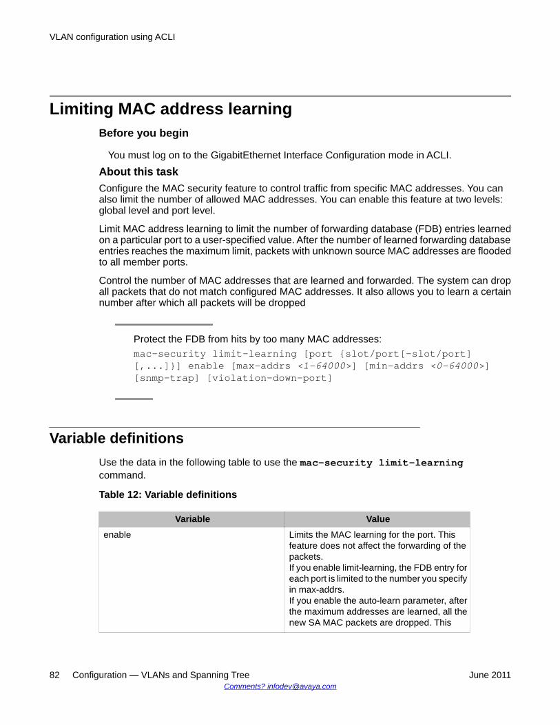
Limiting MAC address learningBefore you begin
You must log on to the GigabitEthernet Interface Configuration mode in ACLI.
About this taskConfigure the MAC security feature to control traffic from specific MAC addresses. You canalso limit the number of allowed MAC addresses. You can enable this feature at two levels:global level and port level.
Limit MAC address learning to limit the number of forwarding database (FDB) entries learnedon a particular port to a user-specified value. After the number of learned forwarding databaseentries reaches the maximum limit, packets with unknown source MAC addresses are floodedto all member ports.
Control the number of MAC addresses that are learned and forwarded. The system can dropall packets that do not match configured MAC addresses. It also allows you to learn a certainnumber after which all packets will be dropped
Protect the FDB from hits by too many MAC addresses:mac-security limit-learning [port {slot/port[-slot/port][,...]}] enable [max-addrs <1–64000>] [min-addrs <0–64000>][snmp-trap] [violation-down-port]
Variable definitionsUse the data in the following table to use the mac-security limit-learningcommand.
Table 12: Variable definitions
Variable Valueenable Limits the MAC learning for the port. This
feature does not affect the forwarding of thepackets.If you enable limit-learning, the FDB entry foreach port is limited to the number you specifyin max-addrs.If you enable the auto-learn parameter, afterthe maximum addresses are learned, all thenew SA MAC packets are dropped. This
VLAN configuration using ACLI
82 Configuration — VLANs and Spanning Tree June 2011Comments? [email protected]
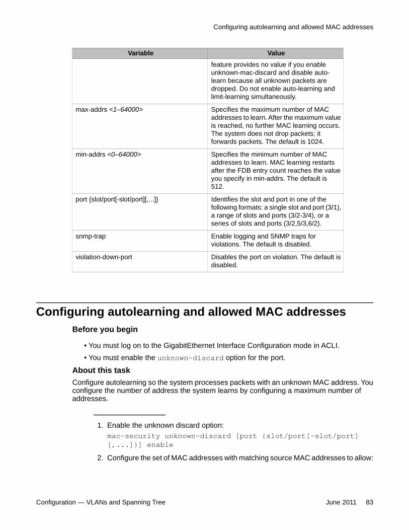
Variable Valuefeature provides no value if you enableunknown-mac-discard and disable auto-learn because all unknown packets aredropped. Do not enable auto-learning andlimit-learning simultaneously.
max-addrs <1–64000> Specifies the maximum number of MACaddresses to learn. After the maximum valueis reached, no further MAC learning occurs.The system does not drop packets; itforwards packets. The default is 1024.
min-addrs <0–64000> Specifies the minimum number of MACaddresses to learn. MAC learning restartsafter the FDB entry count reaches the valueyou specify in min-addrs. The default is512.
port {slot/port[-slot/port][,...]} Identifies the slot and port in one of thefollowing formats: a single slot and port (3/1),a range of slots and ports (3/2-3/4), or aseries of slots and ports (3/2,5/3,6/2).
snmp-trap Enable logging and SNMP traps forviolations. The default is disabled.
violation-down-port Disables the port on violation. The default isdisabled.
Configuring autolearning and allowed MAC addressesBefore you begin
• You must log on to the GigabitEthernet Interface Configuration mode in ACLI.• You must enable the unknown-discard option for the port.
About this taskConfigure autolearning so the system processes packets with an unknown MAC address. Youconfigure the number of address the system learns by configuring a maximum number ofaddresses.
1. Enable the unknown discard option:mac-security unknown-discard [port {slot/port[-slot/port][,...]}] enable
2. Configure the set of MAC addresses with matching source MAC addresses to allow:
Configuring autolearning and allowed MAC addresses
Configuration — VLANs and Spanning Tree June 2011 83
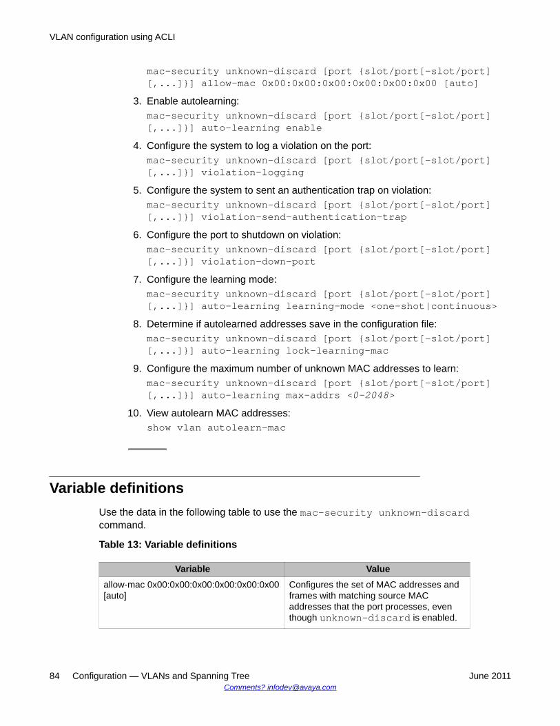
mac-security unknown-discard [port {slot/port[-slot/port][,...]}] allow-mac 0x00:0x00:0x00:0x00:0x00:0x00 [auto]
3. Enable autolearning:mac-security unknown-discard [port {slot/port[-slot/port][,...]}] auto-learning enable
4. Configure the system to log a violation on the port:mac-security unknown-discard [port {slot/port[-slot/port][,...]}] violation-logging
5. Configure the system to sent an authentication trap on violation:mac-security unknown-discard [port {slot/port[-slot/port][,...]}] violation-send-authentication-trap
6. Configure the port to shutdown on violation:mac-security unknown-discard [port {slot/port[-slot/port][,...]}] violation-down-port
7. Configure the learning mode:mac-security unknown-discard [port {slot/port[-slot/port][,...]}] auto-learning learning-mode <one-shot|continuous>
8. Determine if autolearned addresses save in the configuration file:mac-security unknown-discard [port {slot/port[-slot/port][,...]}] auto-learning lock-learning-mac
9. Configure the maximum number of unknown MAC addresses to learn:mac-security unknown-discard [port {slot/port[-slot/port][,...]}] auto-learning max-addrs <0–2048>
10. View autolearn MAC addresses:show vlan autolearn-mac
Variable definitionsUse the data in the following table to use the mac-security unknown-discardcommand.
Table 13: Variable definitions
Variable Valueallow-mac 0x00:0x00:0x00:0x00:0x00:0x00[auto]
Configures the set of MAC addresses andframes with matching source MACaddresses that the port processes, eventhough unknown-discard is enabled.
VLAN configuration using ACLI
84 Configuration — VLANs and Spanning Tree June 2011Comments? [email protected]
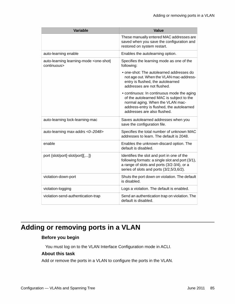
Variable ValueThese manually entered MAC addresses aresaved when you save the configuration andrestored on system restart.
auto-learning enable Enables the autolearning option.
auto-learning learning-mode <one-shot|continuous>
Specifies the learning mode as one of thefollowing:
• one-shot: The autolearned addresses donot age out. When the VLAN mac-address-entry is flushed, the autolearnedaddresses are not flushed.
• continuous: In continuous mode the agingof the autolearned MAC is subject to thenormal aging. When the VLAN mac-address-entry is flushed, the autolearnedaddresses are also flushed.
auto-learning lock-learning-mac Saves autolearned addresses when yousave the configuration file.
auto-learning max-addrs <0–2048> Specifies the total number of unknown MACaddresses to learn. The default is 2048.
enable Enables the unknown-discard option. Thedefault is disabled.
port {slot/port[-slot/port][,...]} Identifies the slot and port in one of thefollowing formats: a single slot and port (3/1),a range of slots and ports (3/2-3/4), or aseries of slots and ports (3/2,5/3,6/2).
violation-down-port Shuts the port down on violation. The defaultis disabled.
violation-logging Logs a violation. The default is enabled.
violation-send-authentication-trap Send an authentication trap on violation. Thedefault is disabled.
Adding or removing ports in a VLANBefore you begin
You must log on to the VLAN Interface Configuration mode in ACLI.
About this taskAdd or remove the ports in a VLAN to configure the ports in the VLAN.
Adding or removing ports in a VLAN
Configuration — VLANs and Spanning Tree June 2011 85
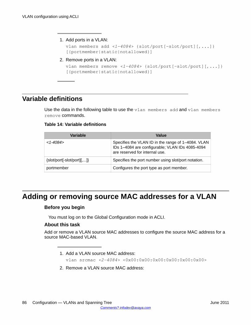
1. Add ports in a VLAN:vlan members add <1-4084> {slot/port[-slot/port][,...]}[{portmember|static|notallowed}]
2. Remove ports in a VLAN:vlan members remove <1-4084> {slot/port[-slot/port][,...]}[{portmember|static|notallowed}]
Variable definitionsUse the data in the following table to use the vlan members add and vlan membersremove commands.
Table 14: Variable definitions
Variable Value<1-4084> Specifies the VLAN ID in the range of 1–4084. VLAN
IDs 1–4084 are configurable; VLAN IDs 4085-4094are reserved for internal use.
{slot/port[-slot/port][,...]} Specifies the port number using slot/port notation.
portmember Configures the port type as port member.
Adding or removing source MAC addresses for a VLANBefore you begin
You must log on to the Global Configuration mode in ACLI.
About this taskAdd or remove a VLAN source MAC addresses to configure the source MAC address for asource MAC-based VLAN.
1. Add a VLAN source MAC address:vlan srcmac <2-4084> <0x00:0x00:0x00:0x00:0x00:0x00>
2. Remove a VLAN source MAC address:
VLAN configuration using ACLI
86 Configuration — VLANs and Spanning Tree June 2011Comments? [email protected]

no vlan srcmac <2-4084> <0x00:0x00:0x00:0x00:0x00:0x00>
Variable definitionsUse the data in the following table to use the vlan srcmac command.
Table 15: Variable definitions
Variable Value<2-4084> Specifies the VLAN ID in the range of 2–4084.
<0x00:0x00:0x00:0x00:0x00:0x00>
Indicates the MAC address.
Configuring VLAN classification precedenceBefore you begin
You must log on to the GigabitEthernet Interface Configuration mode in ACLI.
About this taskConfigure classification precedence to change classification precedence between source-MAC and subnet-based VLANs for a port. You can enable or disable source-MAC-basedclassification and subnet-based classification for a port. You can also enable or disableprotocol-based classification.
1. Enable or disable source-MAC-based VLAN classification for the port:[default] [no] source-mac-vlan [enable] [port {slot/port[-slot/port][,...]}]The default value is enabled.
2. Enable or disable IP subnet-based VLAN classification for the port:[default] [no] subnet-vlan [enable] [port {slot/port[-slot/port][,...]}]The default value is enabled.
3. Enable protocol-based VLAN classification for the port:[default] [no] protocol-vlan [enable] [port {slot/port[-slot/port][,...]}]The default value is enabled.
Configuring VLAN classification precedence
Configuration — VLANs and Spanning Tree June 2011 87
4. Specify whether source-MAC or IP subnet classification takes precedence:policy-vlan-precedence [port {slot/port[-slot/port][,...]}]{source-mac|subnet}The default value is source-mac.
5. Configure the VLAN classification to the default value:default policy-vlan-precedence [port {slot/port[-slot/port][,...]}]The default value is source-mac.
6. Display port VLAN information:show interface gigabitEthernet vlan <1–4084> {slot/port[-slot/port][,...]}
Configuring NLB supportBefore you begin
• You must log on to the VLAN Interface Configuration mode for the VLAN ID in ACLI.• For all modes, configure an IP address on the VLAN enabled with NLB.• In addition, for IGMP-multicast mode, enable IGMP snooping.
About this taskUse Microsoft Network Load Balancer (NLB) to share the workload among multiple clusteringservers. Configure the NLB support on an IP interface to enable or disable the Network LoadBalancer (NLB) support. The default value is NLB support disabled.
1. Enable NLB support on an interface:nlb-mode unicastORnlb-mode multicastORnlb-mode igmp-multicast
2. Exit to Global Configuration mode:exit
3. Optionally, enable multicast MAC flooding:
VLAN configuration using ACLI
88 Configuration — VLANs and Spanning Tree June 2011Comments? [email protected]
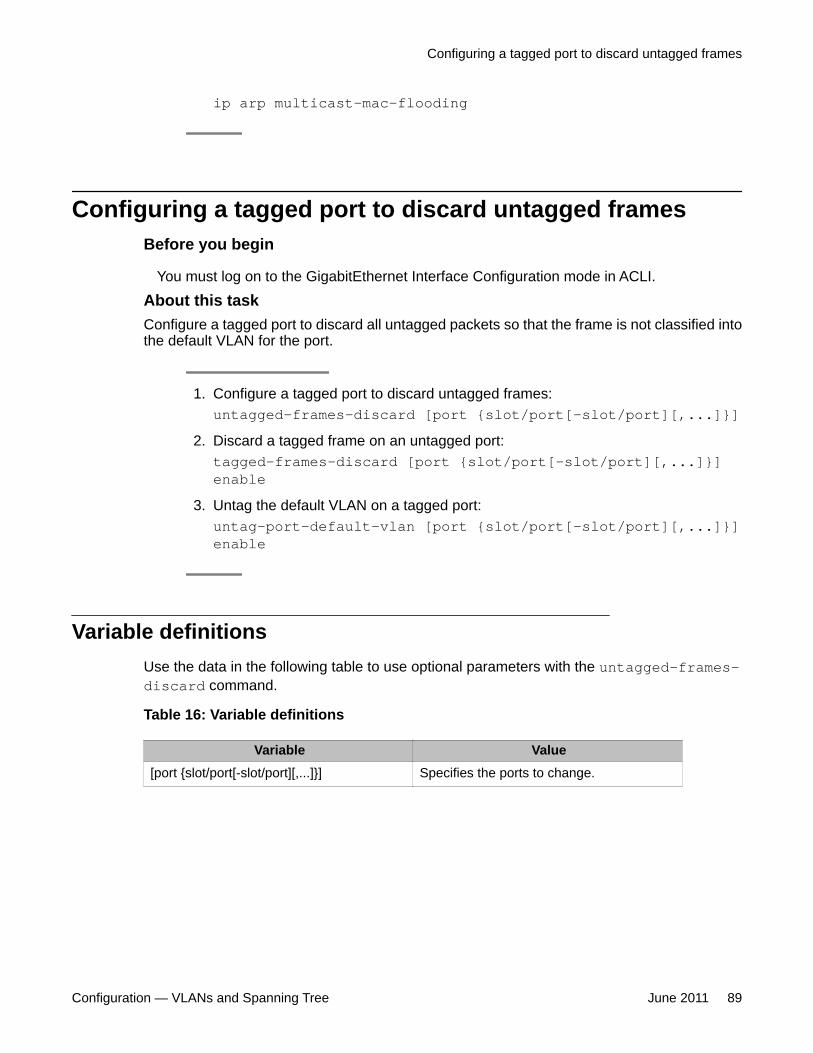
ip arp multicast-mac-flooding
Configuring a tagged port to discard untagged framesBefore you begin
You must log on to the GigabitEthernet Interface Configuration mode in ACLI.
About this taskConfigure a tagged port to discard all untagged packets so that the frame is not classified intothe default VLAN for the port.
1. Configure a tagged port to discard untagged frames:untagged-frames-discard [port {slot/port[-slot/port][,...]}]
2. Discard a tagged frame on an untagged port:tagged-frames-discard [port {slot/port[-slot/port][,...]}]enable
3. Untag the default VLAN on a tagged port:untag-port-default-vlan [port {slot/port[-slot/port][,...]}]enable
Variable definitionsUse the data in the following table to use optional parameters with the untagged-frames-discard command.
Table 16: Variable definitions
Variable Value[port {slot/port[-slot/port][,...]}] Specifies the ports to change.
Configuring a tagged port to discard untagged frames
Configuration — VLANs and Spanning Tree June 2011 89
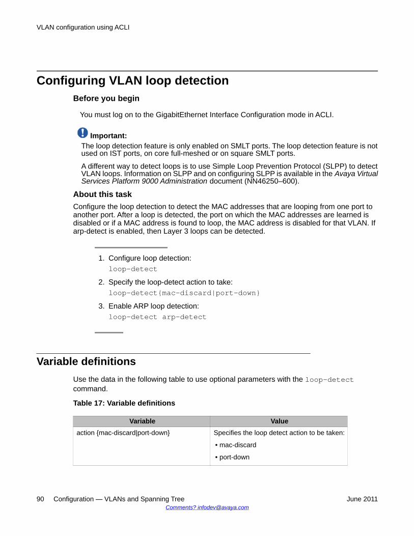
Configuring VLAN loop detectionBefore you begin
You must log on to the GigabitEthernet Interface Configuration mode in ACLI.
Important:The loop detection feature is only enabled on SMLT ports. The loop detection feature is notused on IST ports, on core full-meshed or on square SMLT ports.
A different way to detect loops is to use Simple Loop Prevention Protocol (SLPP) to detectVLAN loops. Information on SLPP and on configuring SLPP is available in the Avaya VirtualServices Platform 9000 Administration document (NN46250–600).
About this taskConfigure the loop detection to detect the MAC addresses that are looping from one port toanother port. After a loop is detected, the port on which the MAC addresses are learned isdisabled or if a MAC address is found to loop, the MAC address is disabled for that VLAN. Ifarp-detect is enabled, then Layer 3 loops can be detected.
1. Configure loop detection:loop-detect
2. Specify the loop-detect action to take:loop-detect{mac-discard|port-down}
3. Enable ARP loop detection:loop-detect arp-detect
Variable definitionsUse the data in the following table to use optional parameters with the loop-detectcommand.
Table 17: Variable definitions
Variable Valueaction {mac-discard|port-down} Specifies the loop detect action to be taken:
• mac-discard
• port-down
VLAN configuration using ACLI
90 Configuration — VLANs and Spanning Tree June 2011Comments? [email protected]
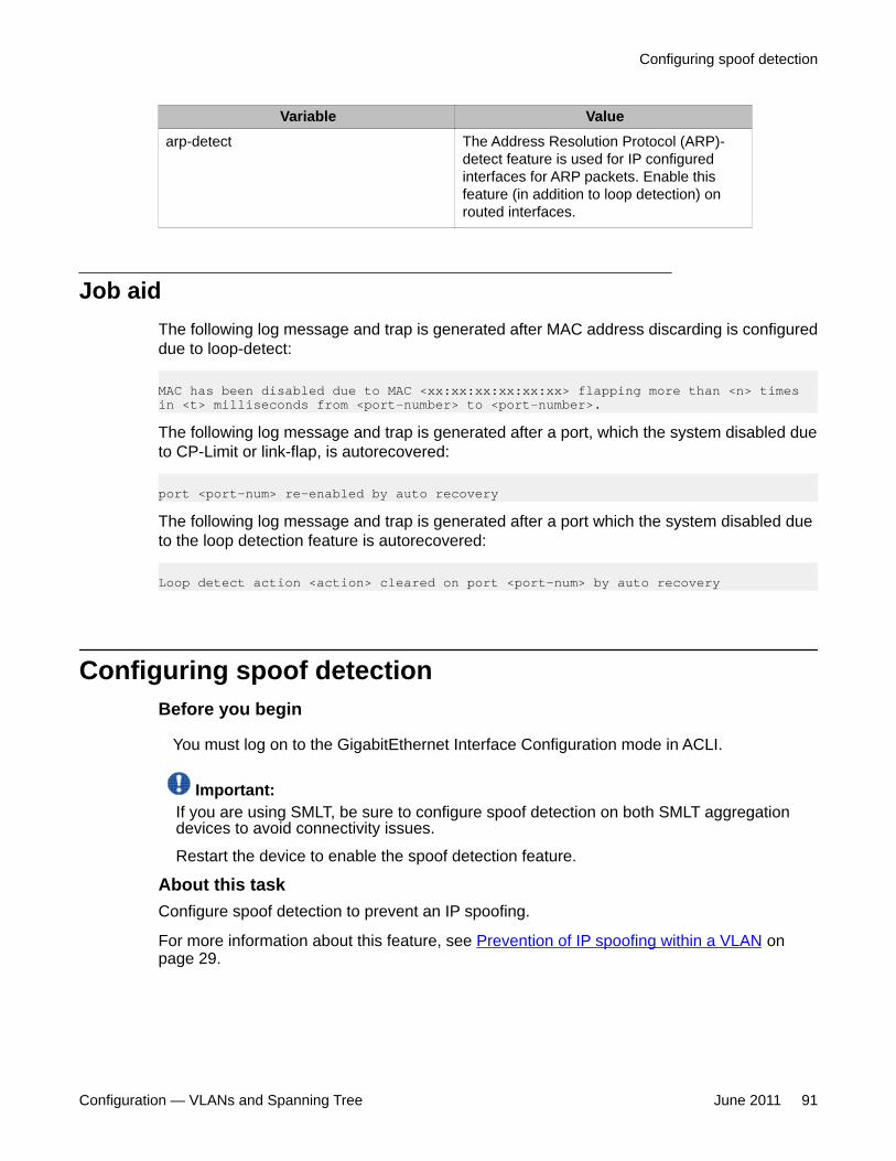
Variable Valuearp-detect The Address Resolution Protocol (ARP)-
detect feature is used for IP configuredinterfaces for ARP packets. Enable thisfeature (in addition to loop detection) onrouted interfaces.
Job aidThe following log message and trap is generated after MAC address discarding is configureddue to loop-detect:
MAC has been disabled due to MAC <xx:xx:xx:xx:xx:xx> flapping more than <n> times in <t> milliseconds from <port-number> to <port-number>.
The following log message and trap is generated after a port, which the system disabled dueto CP-Limit or link-flap, is autorecovered:
port <port-num> re-enabled by auto recovery
The following log message and trap is generated after a port which the system disabled dueto the loop detection feature is autorecovered:
Loop detect action <action> cleared on port <port-num> by auto recovery
Configuring spoof detectionBefore you begin
You must log on to the GigabitEthernet Interface Configuration mode in ACLI.
Important:If you are using SMLT, be sure to configure spoof detection on both SMLT aggregationdevices to avoid connectivity issues.
Restart the device to enable the spoof detection feature.
About this taskConfigure spoof detection to prevent an IP spoofing.
For more information about this feature, see Prevention of IP spoofing within a VLAN onpage 29.
Configuring spoof detection
Configuration — VLANs and Spanning Tree June 2011 91
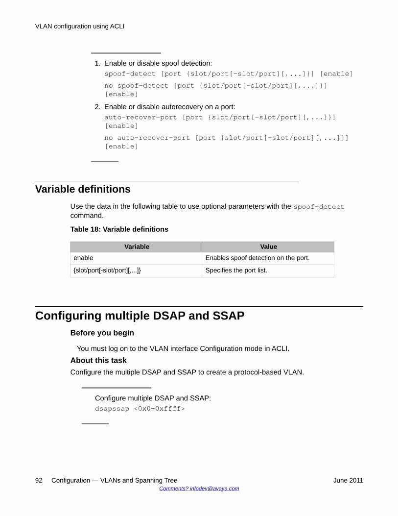
1. Enable or disable spoof detection:spoof-detect [port {slot/port[-slot/port][,...]}] [enable]no spoof-detect [port {slot/port[-slot/port][,...]}][enable]
2. Enable or disable autorecovery on a port:auto-recover-port [port {slot/port[-slot/port][,...]}][enable]no auto-recover-port [port {slot/port[-slot/port][,...]}][enable]
Variable definitionsUse the data in the following table to use optional parameters with the spoof-detectcommand.
Table 18: Variable definitions
Variable Valueenable Enables spoof detection on the port.
{slot/port[-slot/port][,...]} Specifies the port list.
Configuring multiple DSAP and SSAPBefore you begin
You must log on to the VLAN interface Configuration mode in ACLI.
About this taskConfigure the multiple DSAP and SSAP to create a protocol-based VLAN.
Configure multiple DSAP and SSAP:dsapssap <0x0-0xffff>
VLAN configuration using ACLI
92 Configuration — VLANs and Spanning Tree June 2011Comments? [email protected]
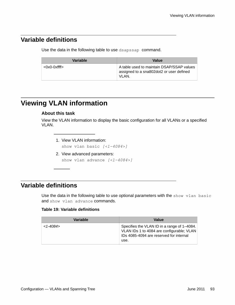
Variable definitionsUse the data in the following table to use dsapssap command.
Variable Value<0x0-0xffff> A table used to maintain DSAP/SSAP values
assigned to a sna802dot2 or user definedVLAN.
Viewing VLAN informationAbout this taskView the VLAN information to display the basic configuration for all VLANs or a specifiedVLAN.
1. View VLAN information:show vlan basic [<1-4084>]
2. View advanced parameters:show vlan advance [<1-4084>]
Variable definitionsUse the data in the following table to use optional parameters with the show vlan basicand show vlan advance commands.
Table 19: Variable definitions
Variable Value<1-4084> Specifies the VLAN ID in a range of 1–4084.
VLAN IDs 1 to 4084 are configurable; VLANIDs 4085-4094 are reserved for internaluse.
Viewing VLAN information
Configuration — VLANs and Spanning Tree June 2011 93
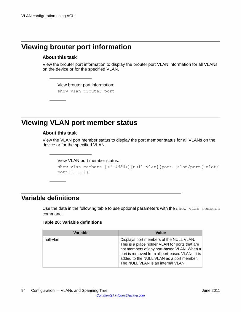
Viewing brouter port informationAbout this taskView the brouter port information to display the brouter port VLAN information for all VLANson the device or for the specified VLAN.
View brouter port information:show vlan brouter-port
Viewing VLAN port member statusAbout this taskView the VLAN port member status to display the port member status for all VLANs on thedevice or for the specified VLAN.
View VLAN port member status:show vlan members [<1–4084>][null-vlan][port {slot/port[-slot/port][,...]}]
Variable definitionsUse the data in the following table to use optional parameters with the show vlan memberscommand.
Table 20: Variable definitions
Variable Valuenull-vlan Displays port members of the NULL VLAN.
This is a place holder VLAN for ports that arenot members of any port-based VLAN. When aport is removed from all port-based VLANs, it isadded to the NULL VLAN as a port member.The NULL VLAN is an internal VLAN.
VLAN configuration using ACLI
94 Configuration — VLANs and Spanning Tree June 2011Comments? [email protected]
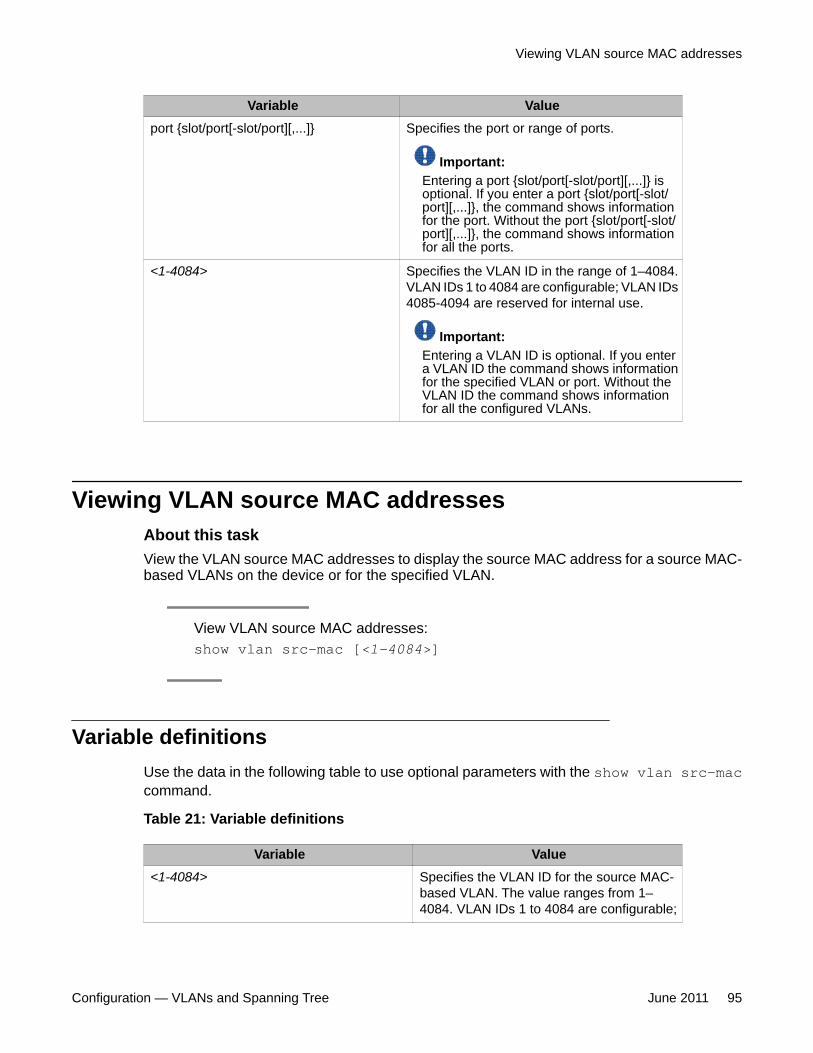
Variable Valueport {slot/port[-slot/port][,...]} Specifies the port or range of ports.
Important:Entering a port {slot/port[-slot/port][,...]} isoptional. If you enter a port {slot/port[-slot/port][,...]}, the command shows informationfor the port. Without the port {slot/port[-slot/port][,...]}, the command shows informationfor all the ports.
<1-4084> Specifies the VLAN ID in the range of 1–4084.VLAN IDs 1 to 4084 are configurable; VLAN IDs4085-4094 are reserved for internal use.
Important:Entering a VLAN ID is optional. If you entera VLAN ID the command shows informationfor the specified VLAN or port. Without theVLAN ID the command shows informationfor all the configured VLANs.
Viewing VLAN source MAC addressesAbout this taskView the VLAN source MAC addresses to display the source MAC address for a source MAC-based VLANs on the device or for the specified VLAN.
View VLAN source MAC addresses:show vlan src-mac [<1-4084>]
Variable definitionsUse the data in the following table to use optional parameters with the show vlan src-maccommand.
Table 21: Variable definitions
Variable Value<1-4084> Specifies the VLAN ID for the source MAC-
based VLAN. The value ranges from 1–4084. VLAN IDs 1 to 4084 are configurable;
Viewing VLAN source MAC addresses
Configuration — VLANs and Spanning Tree June 2011 95
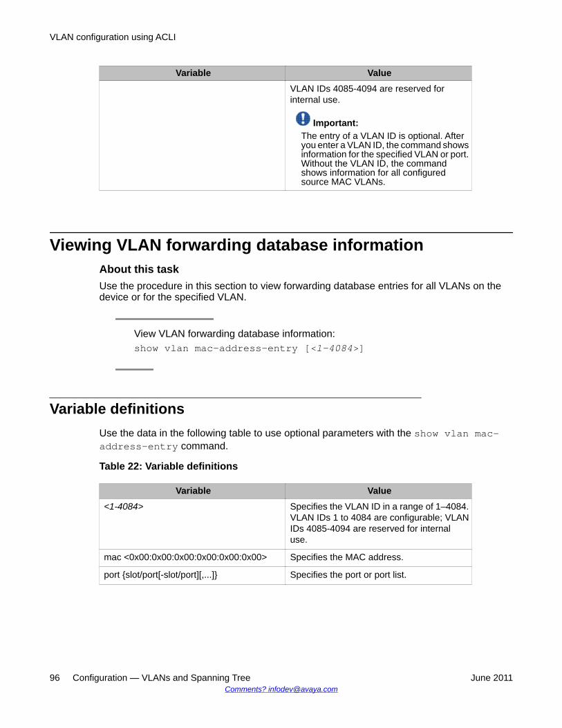
Variable ValueVLAN IDs 4085-4094 are reserved forinternal use.
Important:The entry of a VLAN ID is optional. Afteryou enter a VLAN ID, the command showsinformation for the specified VLAN or port.Without the VLAN ID, the commandshows information for all configuredsource MAC VLANs.
Viewing VLAN forwarding database informationAbout this taskUse the procedure in this section to view forwarding database entries for all VLANs on thedevice or for the specified VLAN.
View VLAN forwarding database information:show vlan mac-address-entry [<1-4084>]
Variable definitionsUse the data in the following table to use optional parameters with the show vlan mac-address-entry command.
Table 22: Variable definitions
Variable Value<1-4084> Specifies the VLAN ID in a range of 1–4084.
VLAN IDs 1 to 4084 are configurable; VLANIDs 4085-4094 are reserved for internaluse.
mac <0x00:0x00:0x00:0x00:0x00:0x00> Specifies the MAC address.
port {slot/port[-slot/port][,...]} Specifies the port or port list.
VLAN configuration using ACLI
96 Configuration — VLANs and Spanning Tree June 2011Comments? [email protected]
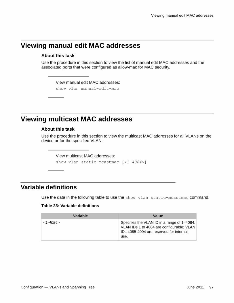
Viewing manual edit MAC addressesAbout this taskUse the procedure in this section to view the list of manual edit MAC addresses and theassociated ports that were configured as allow-mac for MAC security.
View manual edit MAC addresses:show vlan manual-edit-mac
Viewing multicast MAC addressesAbout this taskUse the procedure in this section to view the multicast MAC addresses for all VLANs on thedevice or for the specified VLAN.
View multicast MAC addresses:show vlan static-mcastmac [<1-4084>]
Variable definitionsUse the data in the following table to use the show vlan static-mcastmac command.
Table 23: Variable definitions
Variable Value<1-4084> Specifies the VLAN ID in a range of 1–4084.
VLAN IDs 1 to 4084 are configurable; VLANIDs 4085-4094 are reserved for internaluse.
Viewing manual edit MAC addresses
Configuration — VLANs and Spanning Tree June 2011 97
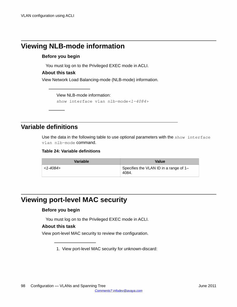
Viewing NLB-mode informationBefore you begin
You must log on to the Privileged EXEC mode in ACLI.
About this taskView Network Load Balancing-mode (NLB-mode) information.
View NLB-mode information:show interface vlan nlb-mode<1–4084>
Variable definitionsUse the data in the following table to use optional parameters with the show interfacevlan nlb-mode command.
Table 24: Variable definitions
Variable Value<1-4084> Specifies the VLAN ID in a range of 1–
4084.
Viewing port-level MAC securityBefore you begin
You must log on to the Privileged EXEC mode in ACLI.
About this taskView port-level MAC security to review the configuration.
1. View port-level MAC security for unknown-discard:
VLAN configuration using ACLI
98 Configuration — VLANs and Spanning Tree June 2011Comments? [email protected]
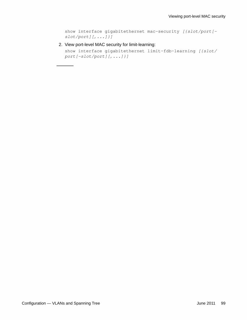
show interface gigabitethernet mac-security [{slot/port[-slot/port][,...]}]
2. View port-level MAC security for limit-learning:show interface gigabitethernet limit—fdb—learning [{slot/port[-slot/port][,...]}]
Viewing port-level MAC security
Configuration — VLANs and Spanning Tree June 2011 99

VLAN configuration using ACLI
100 Configuration — VLANs and Spanning Tree June 2011Comments? [email protected]
Chapter 7: Spanning Tree configurationusing Enterprise DeviceManager
This chapter describes how to create, manage, and monitor spanning tree groups (STG). It also describeshow to configure the Rapid Spanning Tree Protocol (RSTP) and the Multiple Spanning Tree Protocol(MSTP) using the Enterprise Device Manager (EDM).
• Restarting the Avaya Virtual Services Platform 9000 on page 101
• Configuring RSTP global parameters on page 102
• Configuring RSTP ports on page 104
• Viewing RSTP port status on page 106
• Configuring the Spanning Tree mode on page 107
• Configuring MSTP global parameters on page 108
• Configuring CIST ports for MSTP on page 111
• Configuring MSTI bridges for MSTP on page 114
• Configuring MSTI ports for MSTP on page 116
Restarting the Avaya Virtual Services Platform 9000About this taskRestart the Avaya Virtual Services Platform 9000 so that changes to the bootconfig parameters(or other parameters) take effect. For example, you must restart the device to enable a changeto the Spanning Tree mode.
1. In the navigation tree, open the following folders: Configuration > Edit.
2. Click Chassis.
3. In the System tab, locate the ActionGroup1 box.
4. Select saveRuntimeConfig.
5. Click Apply.
Configuration — VLANs and Spanning Tree June 2011 101
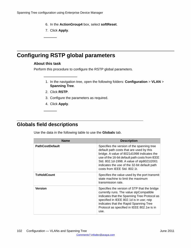
6. In the ActionGroup4 box, select softReset.
7. Click Apply.
Configuring RSTP global parametersAbout this taskPerform this procedure to configure the RSTP global parameters.
1. In the navigation tree, open the following folders: Configuration > VLAN >Spanning Tree.
2. Click RSTP.
3. Configure the parameters as required.
4. Click Apply.
Globals field descriptionsUse the data in the following table to use the Globals tab.
Name DescriptionPathCostDefault Specifies the version of the spanning tree
default path costs that are used by thisbridge. A value of 8021d1998 indicates theuse of the 16-bit default path costs from IEEEStd. 802.1d-1998. A value of stp8021t2001indicates the use of the 32-bit default pathcosts from IEEE Std. 802.1t.
TxHoldCount Specifies the value used by the port transmitstate machine to limit the maximumtransmission rate.
Version Specifies the version of STP that the bridgecurrently runs. The value stpCompatibleindicates that the Spanning Tree Protocol asspecified in IEEE 802.1d is in use; rstpindicates that the Rapid Spanning TreeProtocol as specified in IEEE 802.1w is inuse.
Spanning Tree configuration using Enterprise Device Manager
102 Configuration — VLANs and Spanning Tree June 2011Comments? [email protected]
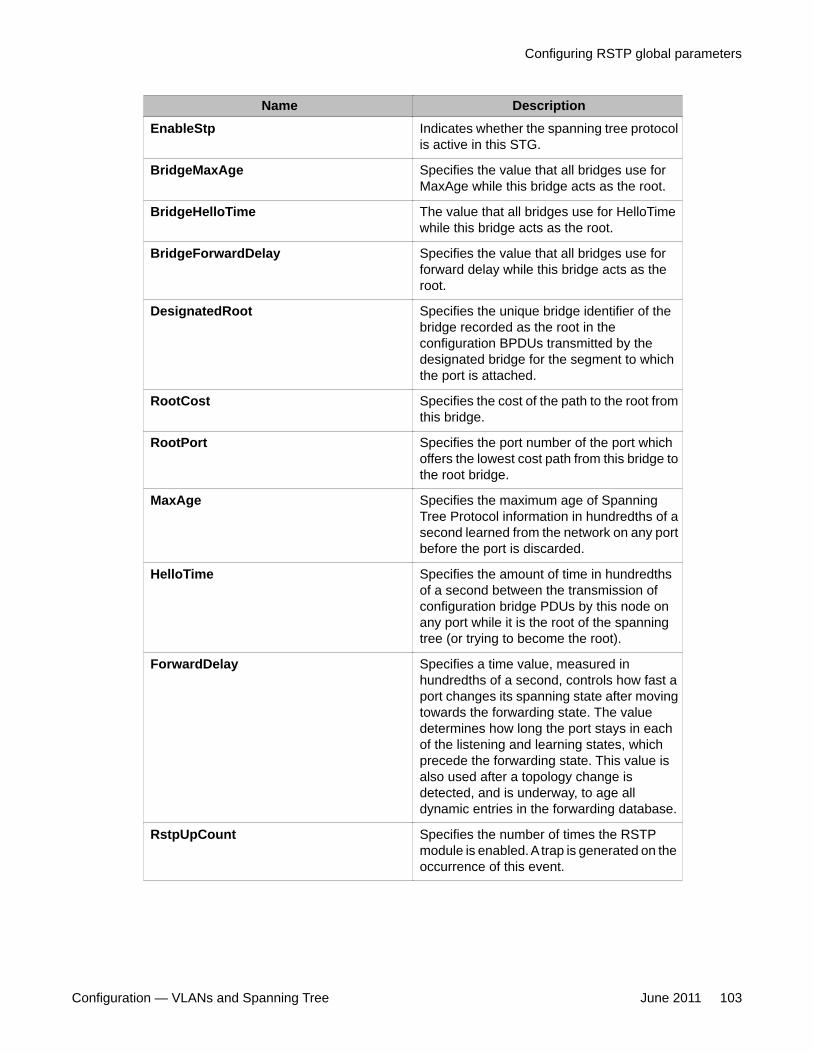
Name DescriptionEnableStp Indicates whether the spanning tree protocol
is active in this STG.
BridgeMaxAge Specifies the value that all bridges use forMaxAge while this bridge acts as the root.
BridgeHelloTime The value that all bridges use for HelloTimewhile this bridge acts as the root.
BridgeForwardDelay Specifies the value that all bridges use forforward delay while this bridge acts as theroot.
DesignatedRoot Specifies the unique bridge identifier of thebridge recorded as the root in theconfiguration BPDUs transmitted by thedesignated bridge for the segment to whichthe port is attached.
RootCost Specifies the cost of the path to the root fromthis bridge.
RootPort Specifies the port number of the port whichoffers the lowest cost path from this bridge tothe root bridge.
MaxAge Specifies the maximum age of SpanningTree Protocol information in hundredths of asecond learned from the network on any portbefore the port is discarded.
HelloTime Specifies the amount of time in hundredthsof a second between the transmission ofconfiguration bridge PDUs by this node onany port while it is the root of the spanningtree (or trying to become the root).
ForwardDelay Specifies a time value, measured inhundredths of a second, controls how fast aport changes its spanning state after movingtowards the forwarding state. The valuedetermines how long the port stays in eachof the listening and learning states, whichprecede the forwarding state. This value isalso used after a topology change isdetected, and is underway, to age alldynamic entries in the forwarding database.
RstpUpCount Specifies the number of times the RSTPmodule is enabled. A trap is generated on theoccurrence of this event.
Configuring RSTP global parameters
Configuration — VLANs and Spanning Tree June 2011 103
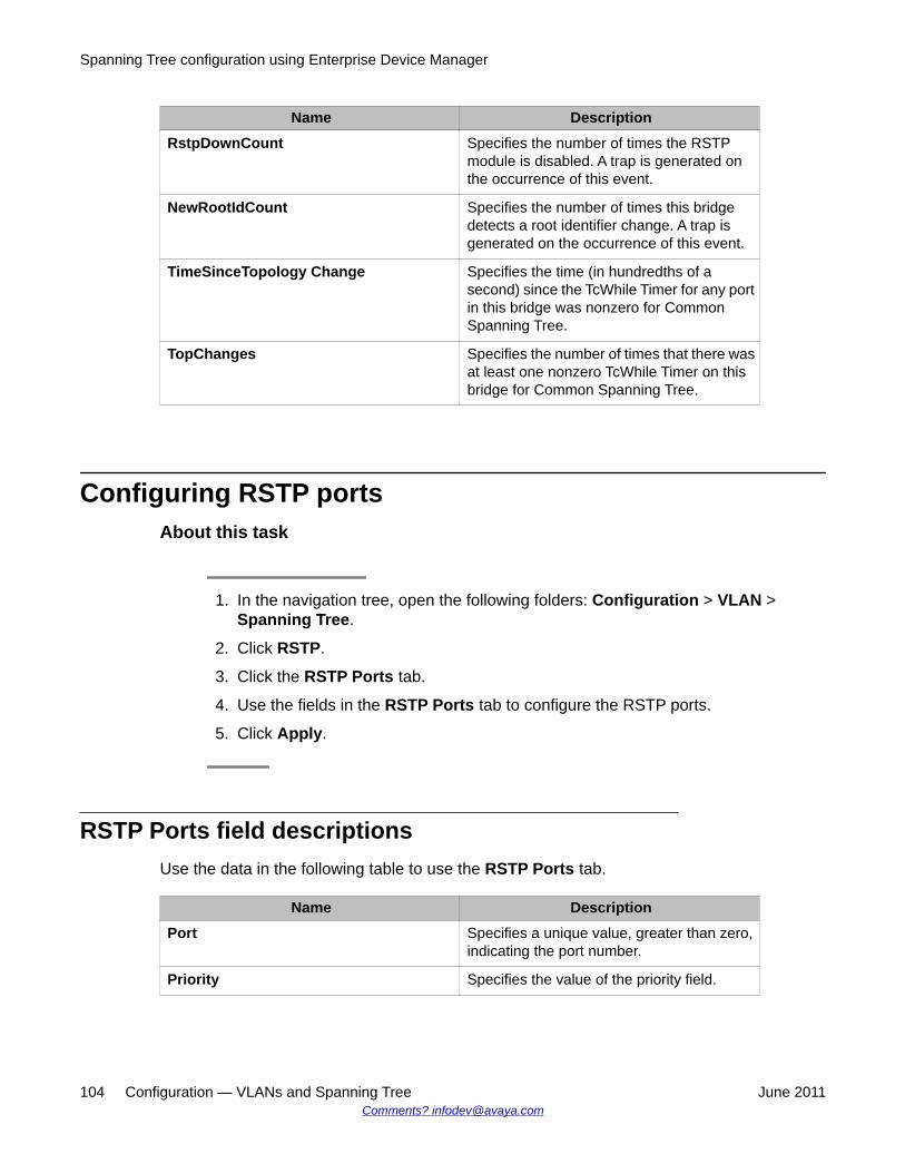
Name DescriptionRstpDownCount Specifies the number of times the RSTP
module is disabled. A trap is generated onthe occurrence of this event.
NewRootIdCount Specifies the number of times this bridgedetects a root identifier change. A trap isgenerated on the occurrence of this event.
TimeSinceTopology Change Specifies the time (in hundredths of asecond) since the TcWhile Timer for any portin this bridge was nonzero for CommonSpanning Tree.
TopChanges Specifies the number of times that there wasat least one nonzero TcWhile Timer on thisbridge for Common Spanning Tree.
Configuring RSTP portsAbout this task
1. In the navigation tree, open the following folders: Configuration > VLAN >Spanning Tree.
2. Click RSTP.
3. Click the RSTP Ports tab.
4. Use the fields in the RSTP Ports tab to configure the RSTP ports.
5. Click Apply.
RSTP Ports field descriptionsUse the data in the following table to use the RSTP Ports tab.
Name DescriptionPort Specifies a unique value, greater than zero,
indicating the port number.
Priority Specifies the value of the priority field.
Spanning Tree configuration using Enterprise Device Manager
104 Configuration — VLANs and Spanning Tree June 2011Comments? [email protected]
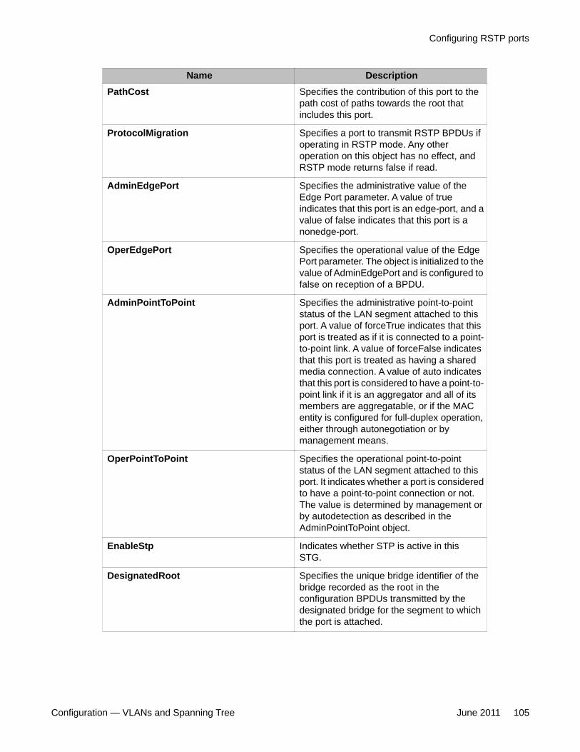
Name DescriptionPathCost Specifies the contribution of this port to the
path cost of paths towards the root thatincludes this port.
ProtocolMigration Specifies a port to transmit RSTP BPDUs ifoperating in RSTP mode. Any otheroperation on this object has no effect, andRSTP mode returns false if read.
AdminEdgePort Specifies the administrative value of theEdge Port parameter. A value of trueindicates that this port is an edge-port, and avalue of false indicates that this port is anonedge-port.
OperEdgePort Specifies the operational value of the EdgePort parameter. The object is initialized to thevalue of AdminEdgePort and is configured tofalse on reception of a BPDU.
AdminPointToPoint Specifies the administrative point-to-pointstatus of the LAN segment attached to thisport. A value of forceTrue indicates that thisport is treated as if it is connected to a point-to-point link. A value of forceFalse indicatesthat this port is treated as having a sharedmedia connection. A value of auto indicatesthat this port is considered to have a point-to-point link if it is an aggregator and all of itsmembers are aggregatable, or if the MACentity is configured for full-duplex operation,either through autonegotiation or bymanagement means.
OperPointToPoint Specifies the operational point-to-pointstatus of the LAN segment attached to thisport. It indicates whether a port is consideredto have a point-to-point connection or not.The value is determined by management orby autodetection as described in theAdminPointToPoint object.
EnableStp Indicates whether STP is active in thisSTG.
DesignatedRoot Specifies the unique bridge identifier of thebridge recorded as the root in theconfiguration BPDUs transmitted by thedesignated bridge for the segment to whichthe port is attached.
Configuring RSTP ports
Configuration — VLANs and Spanning Tree June 2011 105
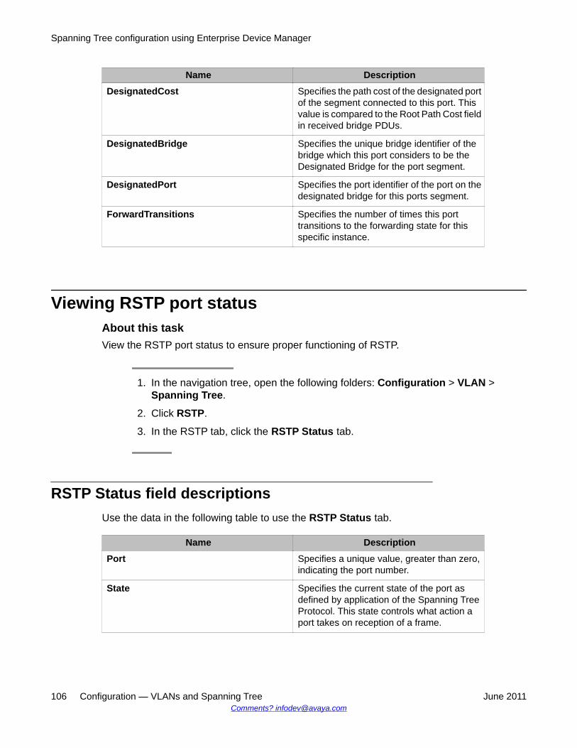
Name DescriptionDesignatedCost Specifies the path cost of the designated port
of the segment connected to this port. Thisvalue is compared to the Root Path Cost fieldin received bridge PDUs.
DesignatedBridge Specifies the unique bridge identifier of thebridge which this port considers to be theDesignated Bridge for the port segment.
DesignatedPort Specifies the port identifier of the port on thedesignated bridge for this ports segment.
ForwardTransitions Specifies the number of times this porttransitions to the forwarding state for thisspecific instance.
Viewing RSTP port statusAbout this taskView the RSTP port status to ensure proper functioning of RSTP.
1. In the navigation tree, open the following folders: Configuration > VLAN >Spanning Tree.
2. Click RSTP.
3. In the RSTP tab, click the RSTP Status tab.
RSTP Status field descriptionsUse the data in the following table to use the RSTP Status tab.
Name DescriptionPort Specifies a unique value, greater than zero,
indicating the port number.
State Specifies the current state of the port asdefined by application of the Spanning TreeProtocol. This state controls what action aport takes on reception of a frame.
Spanning Tree configuration using Enterprise Device Manager
106 Configuration — VLANs and Spanning Tree June 2011Comments? [email protected]
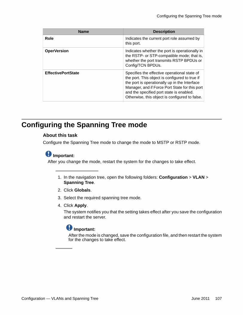
Name DescriptionRole Indicates the current port role assumed by
this port.
OperVersion Indicates whether the port is operationally inthe RSTP- or STP-compatible mode; that is,whether the port transmits RSTP BPDUs orConfig/TCN BPDUs.
EffectivePortState Specifies the effective operational state ofthe port. This object is configured to true ifthe port is operationally up in the InterfaceManager, and if Force Port State for this portand the specified port state is enabled.Otherwise, this object is configured to false.
Configuring the Spanning Tree modeAbout this taskConfigure the Spanning Tree mode to change the mode to MSTP or RSTP mode.
Important:After you change the mode, restart the system for the changes to take effect.
1. In the navigation tree, open the following folders: Configuration > VLAN >Spanning Tree.
2. Click Globals.
3. Select the required spanning tree mode.
4. Click Apply.The system notifies you that the setting takes effect after you save the configurationand restart the server.
Important:After the mode is changed, save the configuration file, and then restart the systemfor the changes to take effect.
Configuring the Spanning Tree mode
Configuration — VLANs and Spanning Tree June 2011 107
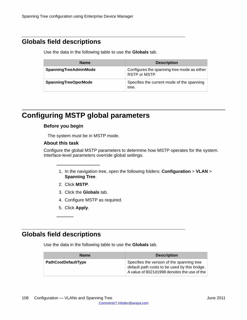
Globals field descriptionsUse the data in the following table to use the Globals tab.
Name DescriptionSpanningTreeAdminMode Configures the spanning tree mode as either
RSTP or MSTP.
SpanningTreeOperMode Specifies the current mode of the spanningtree.
Configuring MSTP global parametersBefore you begin
The system must be in MSTP mode.
About this taskConfigure the global MSTP parameters to determine how MSTP operates for the system.Interface-level parameters override global settings.
1. In the navigation tree, open the following folders: Configuration > VLAN >Spanning Tree.
2. Click MSTP.
3. Click the Globals tab.
4. Configure MSTP as required.
5. Click Apply.
Globals field descriptionsUse the data in the following table to use the Globals tab.
Name DescriptionPathCostDefaultType Specifies the version of the spanning tree
default path costs to be used by this bridge.A value of 8021d1998 denotes the use of the
Spanning Tree configuration using Enterprise Device Manager
108 Configuration — VLANs and Spanning Tree June 2011Comments? [email protected]
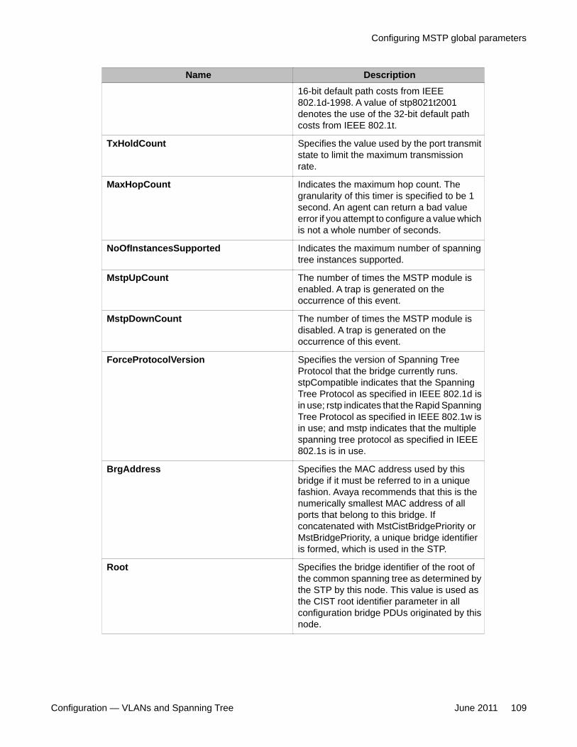
Name Description16-bit default path costs from IEEE802.1d-1998. A value of stp8021t2001denotes the use of the 32-bit default pathcosts from IEEE 802.1t.
TxHoldCount Specifies the value used by the port transmitstate to limit the maximum transmissionrate.
MaxHopCount Indicates the maximum hop count. Thegranularity of this timer is specified to be 1second. An agent can return a bad valueerror if you attempt to configure a value whichis not a whole number of seconds.
NoOfInstancesSupported Indicates the maximum number of spanningtree instances supported.
MstpUpCount The number of times the MSTP module isenabled. A trap is generated on theoccurrence of this event.
MstpDownCount The number of times the MSTP module isdisabled. A trap is generated on theoccurrence of this event.
ForceProtocolVersion Specifies the version of Spanning TreeProtocol that the bridge currently runs.stpCompatible indicates that the SpanningTree Protocol as specified in IEEE 802.1d isin use; rstp indicates that the Rapid SpanningTree Protocol as specified in IEEE 802.1w isin use; and mstp indicates that the multiplespanning tree protocol as specified in IEEE802.1s is in use.
BrgAddress Specifies the MAC address used by thisbridge if it must be referred to in a uniquefashion. Avaya recommends that this is thenumerically smallest MAC address of allports that belong to this bridge. Ifconcatenated with MstCistBridgePriority orMstBridgePriority, a unique bridge identifieris formed, which is used in the STP.
Root Specifies the bridge identifier of the root ofthe common spanning tree as determined bythe STP by this node. This value is used asthe CIST root identifier parameter in allconfiguration bridge PDUs originated by thisnode.
Configuring MSTP global parameters
Configuration — VLANs and Spanning Tree June 2011 109
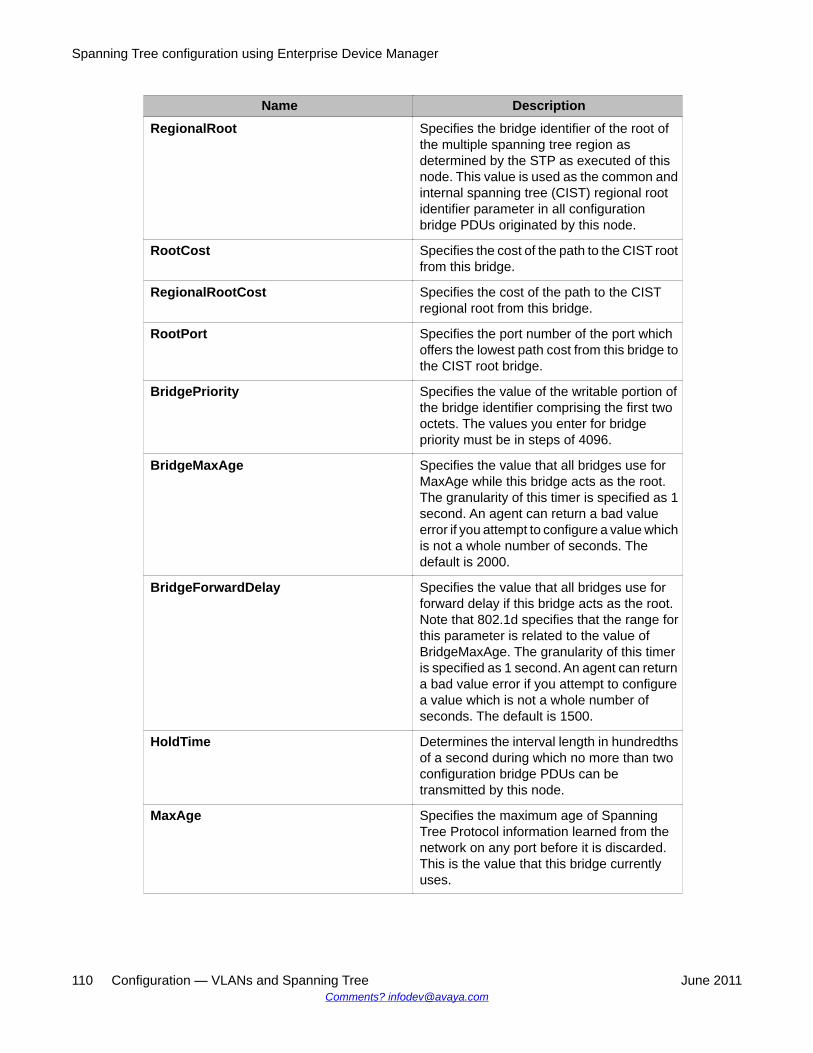
Name DescriptionRegionalRoot Specifies the bridge identifier of the root of
the multiple spanning tree region asdetermined by the STP as executed of thisnode. This value is used as the common andinternal spanning tree (CIST) regional rootidentifier parameter in all configurationbridge PDUs originated by this node.
RootCost Specifies the cost of the path to the CIST rootfrom this bridge.
RegionalRootCost Specifies the cost of the path to the CISTregional root from this bridge.
RootPort Specifies the port number of the port whichoffers the lowest path cost from this bridge tothe CIST root bridge.
BridgePriority Specifies the value of the writable portion ofthe bridge identifier comprising the first twooctets. The values you enter for bridgepriority must be in steps of 4096.
BridgeMaxAge Specifies the value that all bridges use forMaxAge while this bridge acts as the root.The granularity of this timer is specified as 1second. An agent can return a bad valueerror if you attempt to configure a value whichis not a whole number of seconds. Thedefault is 2000.
BridgeForwardDelay Specifies the value that all bridges use forforward delay if this bridge acts as the root.Note that 802.1d specifies that the range forthis parameter is related to the value ofBridgeMaxAge. The granularity of this timeris specified as 1 second. An agent can returna bad value error if you attempt to configurea value which is not a whole number ofseconds. The default is 1500.
HoldTime Determines the interval length in hundredthsof a second during which no more than twoconfiguration bridge PDUs can betransmitted by this node.
MaxAge Specifies the maximum age of SpanningTree Protocol information learned from thenetwork on any port before it is discarded.This is the value that this bridge currentlyuses.
Spanning Tree configuration using Enterprise Device Manager
110 Configuration — VLANs and Spanning Tree June 2011Comments? [email protected]
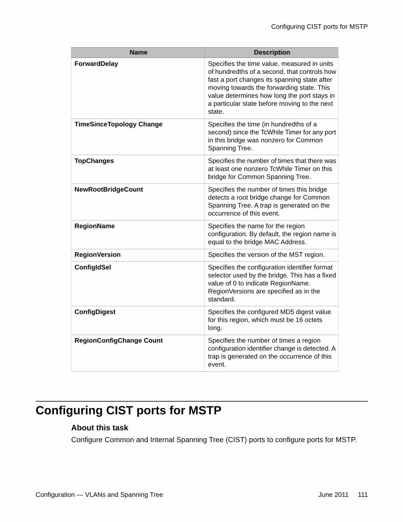
Name DescriptionForwardDelay Specifies the time value, measured in units
of hundredths of a second, that controls howfast a port changes its spanning state aftermoving towards the forwarding state. Thisvalue determines how long the port stays ina particular state before moving to the nextstate.
TimeSinceTopology Change Specifies the time (in hundredths of asecond) since the TcWhile Timer for any portin this bridge was nonzero for CommonSpanning Tree.
TopChanges Specifies the number of times that there wasat least one nonzero TcWhile Timer on thisbridge for Common Spanning Tree.
NewRootBridgeCount Specifies the number of times this bridgedetects a root bridge change for CommonSpanning Tree. A trap is generated on theoccurrence of this event.
RegionName Specifies the name for the regionconfiguration. By default, the region name isequal to the bridge MAC Address.
RegionVersion Specifies the version of the MST region.
ConfigIdSel Specifies the configuration identifier formatselector used by the bridge. This has a fixedvalue of 0 to indicate RegionName.RegionVersions are specified as in thestandard.
ConfigDigest Specifies the configured MD5 digest valuefor this region, which must be 16 octetslong.
RegionConfigChange Count Specifies the number of times a regionconfiguration identifier change is detected. Atrap is generated on the occurrence of thisevent.
Configuring CIST ports for MSTPAbout this taskConfigure Common and Internal Spanning Tree (CIST) ports to configure ports for MSTP.
Configuring CIST ports for MSTP
Configuration — VLANs and Spanning Tree June 2011 111
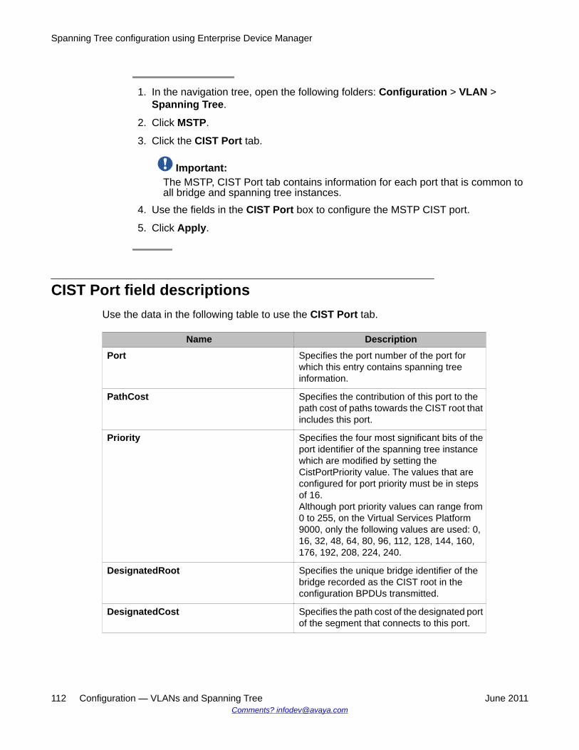
1. In the navigation tree, open the following folders: Configuration > VLAN >Spanning Tree.
2. Click MSTP.
3. Click the CIST Port tab.
Important:The MSTP, CIST Port tab contains information for each port that is common toall bridge and spanning tree instances.
4. Use the fields in the CIST Port box to configure the MSTP CIST port.
5. Click Apply.
CIST Port field descriptionsUse the data in the following table to use the CIST Port tab.
Name DescriptionPort Specifies the port number of the port for
which this entry contains spanning treeinformation.
PathCost Specifies the contribution of this port to thepath cost of paths towards the CIST root thatincludes this port.
Priority Specifies the four most significant bits of theport identifier of the spanning tree instancewhich are modified by setting theCistPortPriority value. The values that areconfigured for port priority must be in stepsof 16.Although port priority values can range from0 to 255, on the Virtual Services Platform9000, only the following values are used: 0,16, 32, 48, 64, 80, 96, 112, 128, 144, 160,176, 192, 208, 224, 240.
DesignatedRoot Specifies the unique bridge identifier of thebridge recorded as the CIST root in theconfiguration BPDUs transmitted.
DesignatedCost Specifies the path cost of the designated portof the segment that connects to this port.
Spanning Tree configuration using Enterprise Device Manager
112 Configuration — VLANs and Spanning Tree June 2011Comments? [email protected]
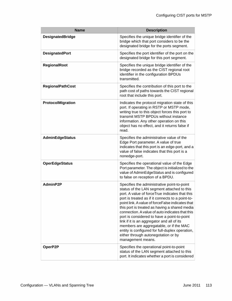
Name DescriptionDesignatedBridge Specifies the unique bridge identifier of the
bridge which that port considers to be thedesignated bridge for the ports segment.
DesignatedPort Specifies the port identifier of the port on thedesignated bridge for this port segment.
RegionalRoot Specifies the unique bridge identifier of thebridge recorded as the CIST regional rootidentifier in the configuration BPDUstransmitted.
RegionalPathCost Specifies the contribution of this port to thepath cost of paths towards the CIST regionalroot that include this port.
ProtocolMigration Indicates the protocol migration state of thisport. If operating in RSTP or MSTP mode,writing true to this object forces this port totransmit MSTP BPDUs without instanceinformation. Any other operation on thisobject has no effect, and it returns false ifread.
AdminEdgeStatus Specifies the administrative value of theEdge Port parameter. A value of trueindicates that this port is an edge-port, and avalue of false indicates that this port is anonedge-port.
OperEdgeStatus Specifies the operational value of the EdgePort parameter. The object is initialized to thevalue of AdminEdgeStatus and is configuredto false on reception of a BPDU.
AdminP2P Specifies the administrative point-to-pointstatus of the LAN segment attached to thisport. A value of forceTrue indicates that thisport is treated as if it connects to a point-to-point link. A value of forceFalse indicates thatthis port is treated as having a shared mediaconnection. A value of auto indicates that thisport is considered to have a point-to-pointlink if it is an aggregator and all of itsmembers are aggregatable, or if the MACentity is configured for full-duplex operation,either through autonegotation or bymanagement means.
OperP2P Specifies the operational point-to-pointstatus of the LAN segment attached to thisport. It indicates whether a port is considered
Configuring CIST ports for MSTP
Configuration — VLANs and Spanning Tree June 2011 113
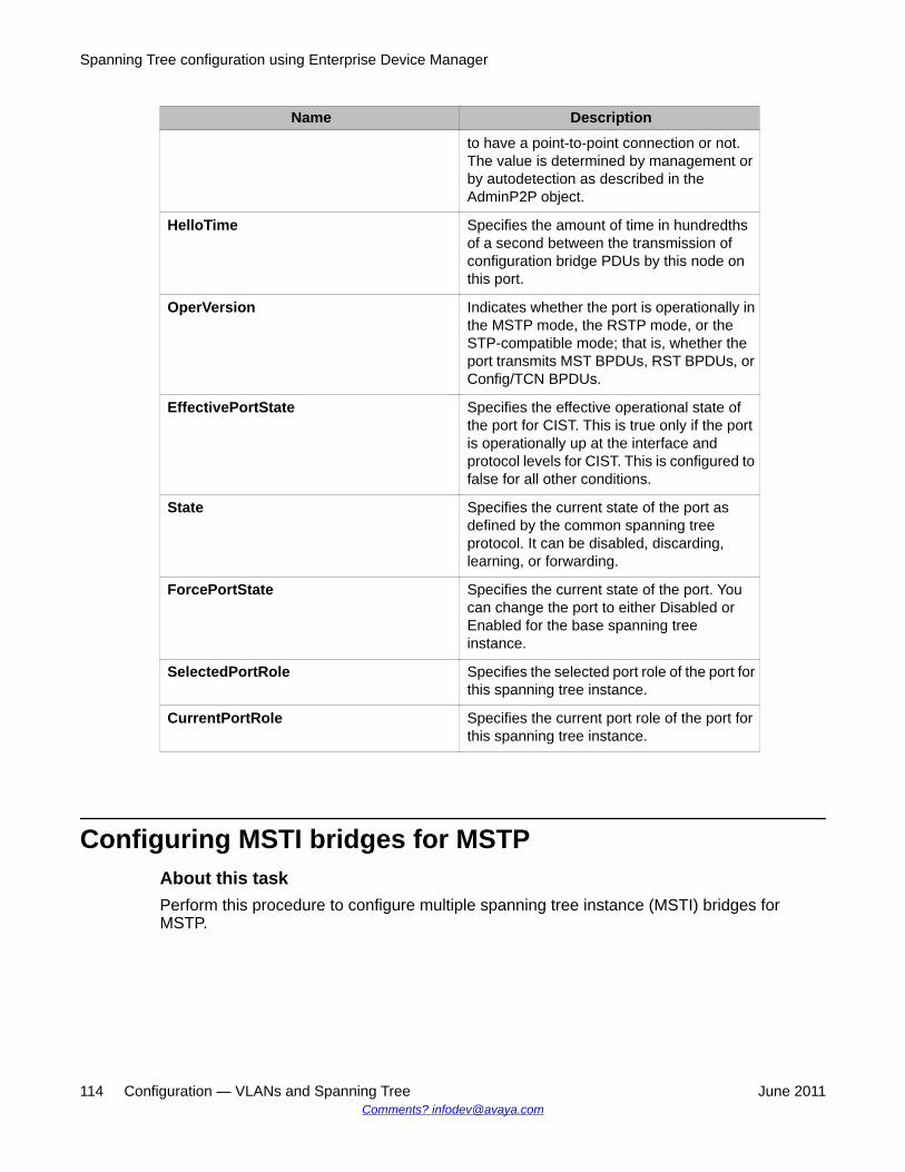
Name Descriptionto have a point-to-point connection or not.The value is determined by management orby autodetection as described in theAdminP2P object.
HelloTime Specifies the amount of time in hundredthsof a second between the transmission ofconfiguration bridge PDUs by this node onthis port.
OperVersion Indicates whether the port is operationally inthe MSTP mode, the RSTP mode, or theSTP-compatible mode; that is, whether theport transmits MST BPDUs, RST BPDUs, orConfig/TCN BPDUs.
EffectivePortState Specifies the effective operational state ofthe port for CIST. This is true only if the portis operationally up at the interface andprotocol levels for CIST. This is configured tofalse for all other conditions.
State Specifies the current state of the port asdefined by the common spanning treeprotocol. It can be disabled, discarding,learning, or forwarding.
ForcePortState Specifies the current state of the port. Youcan change the port to either Disabled orEnabled for the base spanning treeinstance.
SelectedPortRole Specifies the selected port role of the port forthis spanning tree instance.
CurrentPortRole Specifies the current port role of the port forthis spanning tree instance.
Configuring MSTI bridges for MSTPAbout this taskPerform this procedure to configure multiple spanning tree instance (MSTI) bridges forMSTP.
Spanning Tree configuration using Enterprise Device Manager
114 Configuration — VLANs and Spanning Tree June 2011Comments? [email protected]
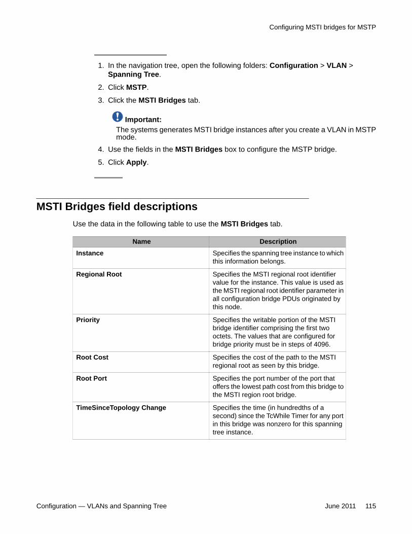
1. In the navigation tree, open the following folders: Configuration > VLAN >Spanning Tree.
2. Click MSTP.
3. Click the MSTI Bridges tab.
Important:The systems generates MSTI bridge instances after you create a VLAN in MSTPmode.
4. Use the fields in the MSTI Bridges box to configure the MSTP bridge.
5. Click Apply.
MSTI Bridges field descriptionsUse the data in the following table to use the MSTI Bridges tab.
Name DescriptionInstance Specifies the spanning tree instance to which
this information belongs.
Regional Root Specifies the MSTI regional root identifiervalue for the instance. This value is used asthe MSTI regional root identifier parameter inall configuration bridge PDUs originated bythis node.
Priority Specifies the writable portion of the MSTIbridge identifier comprising the first twooctets. The values that are configured forbridge priority must be in steps of 4096.
Root Cost Specifies the cost of the path to the MSTIregional root as seen by this bridge.
Root Port Specifies the port number of the port thatoffers the lowest path cost from this bridge tothe MSTI region root bridge.
TimeSinceTopology Change Specifies the time (in hundredths of asecond) since the TcWhile Timer for any portin this bridge was nonzero for this spanningtree instance.
Configuring MSTI bridges for MSTP
Configuration — VLANs and Spanning Tree June 2011 115
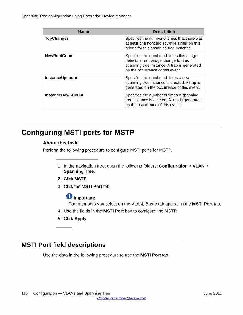
Name DescriptionTopChanges Specifies the number of times that there was
at least one nonzero TcWhile Timer on thisbridge for this spanning tree instance.
NewRootCount Specifies the number of times this bridgedetects a root bridge change for thisspanning tree instance. A trap is generatedon the occurrence of this event.
InstanceUpcount Specifies the number of times a newspanning tree instance is created. A trap isgenerated on the occurrence of this event.
InstanceDownCount Specifies the number of times a spanningtree instance is deleted. A trap is generatedon the occurrence of this event.
Configuring MSTI ports for MSTPAbout this taskPerform the following procedure to configure MSTI ports for MSTP.
1. In the navigation tree, open the following folders: Configuration > VLAN >Spanning Tree.
2. Click MSTP.
3. Click the MSTI Port tab.
Important:Port members you select on the VLAN, Basic tab appear in the MSTI Port tab.
4. Use the fields in the MSTI Port box to configure the MSTP.
5. Click Apply.
MSTI Port field descriptionsUse the data in the following procedure to use the MSTI Port tab.
Spanning Tree configuration using Enterprise Device Manager
116 Configuration — VLANs and Spanning Tree June 2011Comments? [email protected]
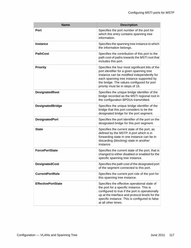
Name DescriptionPort Specifies the port number of the port for
which this entry contains spanning treeinformation.
Instance Specifies the spanning tree instance to whichthe information belongs.
PathCost Specifies the contribution of this port to thepath cost of paths towards the MSTI root thatincludes this port.
Priority Specifies the four most significant bits of theport identifier for a given spanning treeinstance can be modified independently foreach spanning tree instance supported bythe bridge. The values configured for portpriority must be in steps of 16.
DesignatedRoot Specifies the unique bridge identifier of thebridge recorded as the MSTI regional root inthe configuration BPDUs transmitted.
DesignatedBridge Specifies the unique bridge identifier of thebridge that this port considers to be thedesignated bridge for the port segment.
DesignatedPort Specifies the port identifier of the port on thedesignated bridge for this port segment.
State Specifies the current state of the port, asdefined by the MSTP. A port which is inforwarding state in one instance can be indiscarding (blocking) state in anotherinstance.
ForcePortState Specifies the current state of the port, that ischanged to either disabled or enabled for thespecific spanning tree instance.
DesignatedCost Specifies the path cost of the designated portof the segment connected to this port.
CurrentPortRole Specifies the current port role of the port forthis spanning tree instance.
EffectivePortState Specifies the effective operational state ofthe port for a specific instance. This isconfigured to true if the port is operationallyup at the interface and protocol levels for thespecific instance. This is configured to falseat all other times.
Configuring MSTI ports for MSTP
Configuration — VLANs and Spanning Tree June 2011 117

Spanning Tree configuration using Enterprise Device Manager
118 Configuration — VLANs and Spanning Tree June 2011Comments? [email protected]
Chapter 8: Spanning Tree configurationusing ACLI
This chapter describes how to configure the Spanning Tree mode, MSTP, and RSTP using the AvayaCommand Line Interface (ACLI) commands.
Important:The Avaya Virtual Services Platform 9000 supports up to 64 STGs in a device.
Following is the list of procedures in STP configuration:
• Configuring Spanning Tree on page 120
• Configuring Rapid Spanning Tree Protocol on page 120
• Configuring Rapid Spanning Tree Protocol for a port on page 122
• Configuring the Rapid Spanning Tree Protocol version on page 123
• Viewing the global RSTP configuration information on page 124
• Viewing RSTP statistics on page 124
• Viewing the RSTP status on page 124
• Viewing the RSTP configuration information on page 125
• Viewing the RSTP status for a port on page 125
• Viewing RSTP information for a selected port on page 126
• Viewing the RSTP role on page 127
• Viewing spanning tree configuration on page 127
• Configuring Multiple Spanning Tree Protocol on page 128
• Configuring MSTP MSTI options on page 129
• Configuring Ethernet MSTP on page 130
• Configuring Ethernet MSTP MSTI on page 131
• Viewing MSTP configurations on page 132
• Viewing MSTP status on page 132
• Viewing MSTP port information on page 133
• Viewing MSTP MSTI information on page 133
• Viewing MSTP statistics on page 134
Configuration — VLANs and Spanning Tree June 2011 119
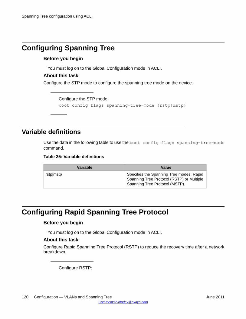
Configuring Spanning TreeBefore you begin
You must log on to the Global Configuration mode in ACLI.
About this taskConfigure the STP mode to configure the spanning tree mode on the device.
Configure the STP mode:boot config flags spanning-tree-mode {rstp|mstp}
Variable definitionsUse the data in the following table to use the boot config flags spanning-tree-modecommand.
Table 25: Variable definitions
Variable Valuerstp|mstp Specifies the Spanning Tree modes: Rapid
Spanning Tree Protocol (RSTP) or MultipleSpanning Tree Protocol (MSTP).
Configuring Rapid Spanning Tree ProtocolBefore you begin
You must log on to the Global Configuration mode in ACLI.
About this taskConfigure Rapid Spanning Tree Protocol (RSTP) to reduce the recovery time after a networkbreakdown.
Configure RSTP:
Spanning Tree configuration using ACLI
120 Configuration — VLANs and Spanning Tree June 2011Comments? [email protected]
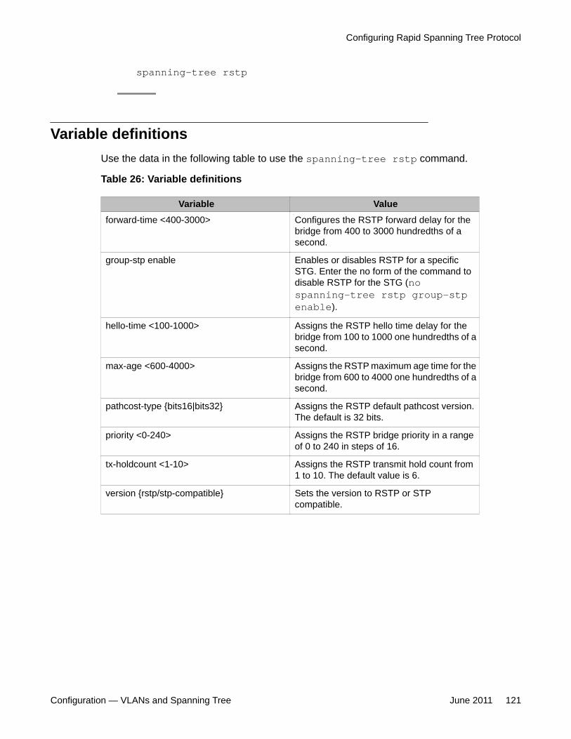
spanning-tree rstp
Variable definitionsUse the data in the following table to use the spanning-tree rstp command.
Table 26: Variable definitions
Variable Valueforward-time <400-3000> Configures the RSTP forward delay for the
bridge from 400 to 3000 hundredths of asecond.
group-stp enable Enables or disables RSTP for a specificSTG. Enter the no form of the command todisable RSTP for the STG (nospanning-tree rstp group-stpenable).
hello-time <100-1000> Assigns the RSTP hello time delay for thebridge from 100 to 1000 one hundredths of asecond.
max-age <600-4000> Assigns the RSTP maximum age time for thebridge from 600 to 4000 one hundredths of asecond.
pathcost-type {bits16|bits32} Assigns the RSTP default pathcost version.The default is 32 bits.
priority <0-240> Assigns the RSTP bridge priority in a rangeof 0 to 240 in steps of 16.
tx-holdcount <1-10> Assigns the RSTP transmit hold count from1 to 10. The default value is 6.
version {rstp/stp-compatible} Sets the version to RSTP or STPcompatible.
Configuring Rapid Spanning Tree Protocol
Configuration — VLANs and Spanning Tree June 2011 121
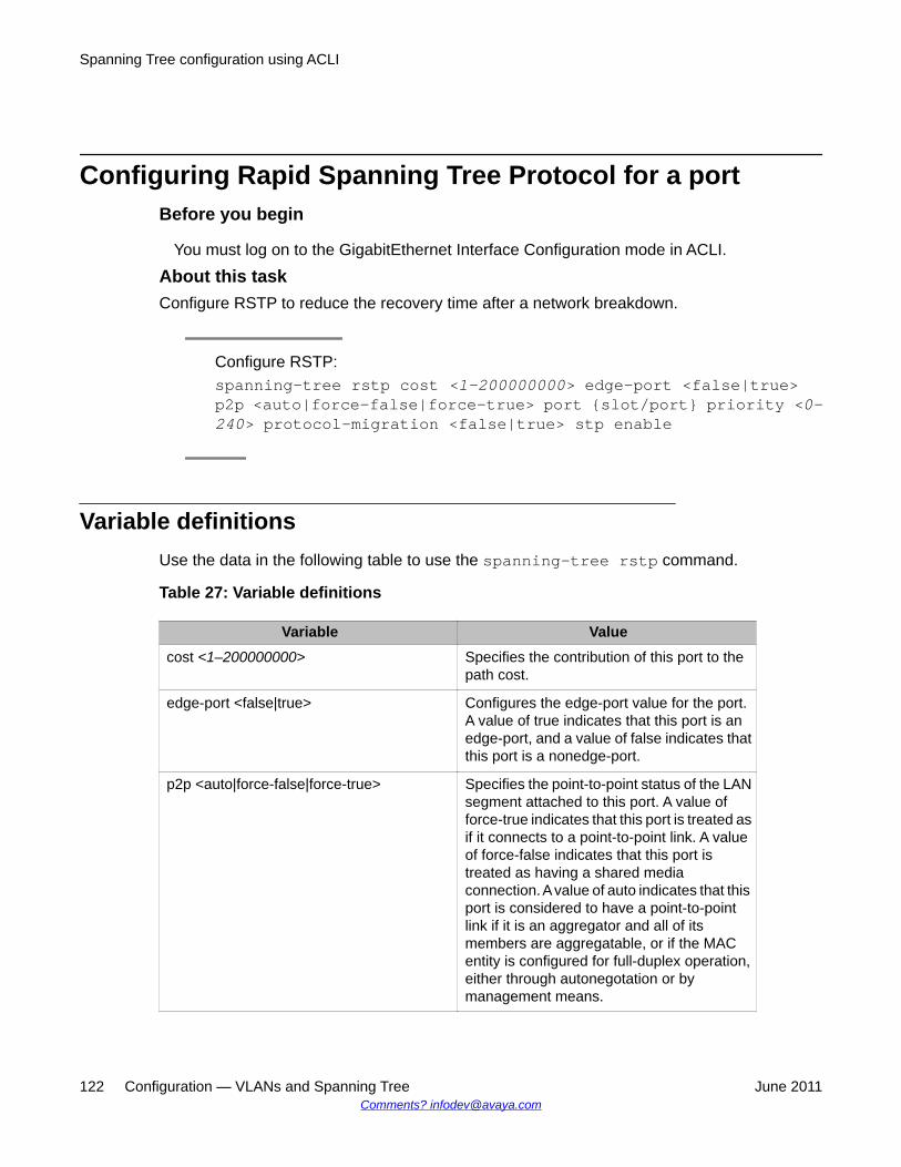
Configuring Rapid Spanning Tree Protocol for a portBefore you begin
You must log on to the GigabitEthernet Interface Configuration mode in ACLI.
About this taskConfigure RSTP to reduce the recovery time after a network breakdown.
Configure RSTP:spanning-tree rstp cost <1–200000000> edge-port <false|true>p2p <auto|force-false|force-true> port {slot/port} priority <0–240> protocol-migration <false|true> stp enable
Variable definitionsUse the data in the following table to use the spanning-tree rstp command.
Table 27: Variable definitions
Variable Valuecost <1–200000000> Specifies the contribution of this port to the
path cost.
edge-port <false|true> Configures the edge-port value for the port.A value of true indicates that this port is anedge-port, and a value of false indicates thatthis port is a nonedge-port.
p2p <auto|force-false|force-true> Specifies the point-to-point status of the LANsegment attached to this port. A value offorce-true indicates that this port is treated asif it connects to a point-to-point link. A valueof force-false indicates that this port istreated as having a shared mediaconnection. A value of auto indicates that thisport is considered to have a point-to-pointlink if it is an aggregator and all of itsmembers are aggregatable, or if the MACentity is configured for full-duplex operation,either through autonegotation or bymanagement means.
Spanning Tree configuration using ACLI
122 Configuration — VLANs and Spanning Tree June 2011Comments? [email protected]
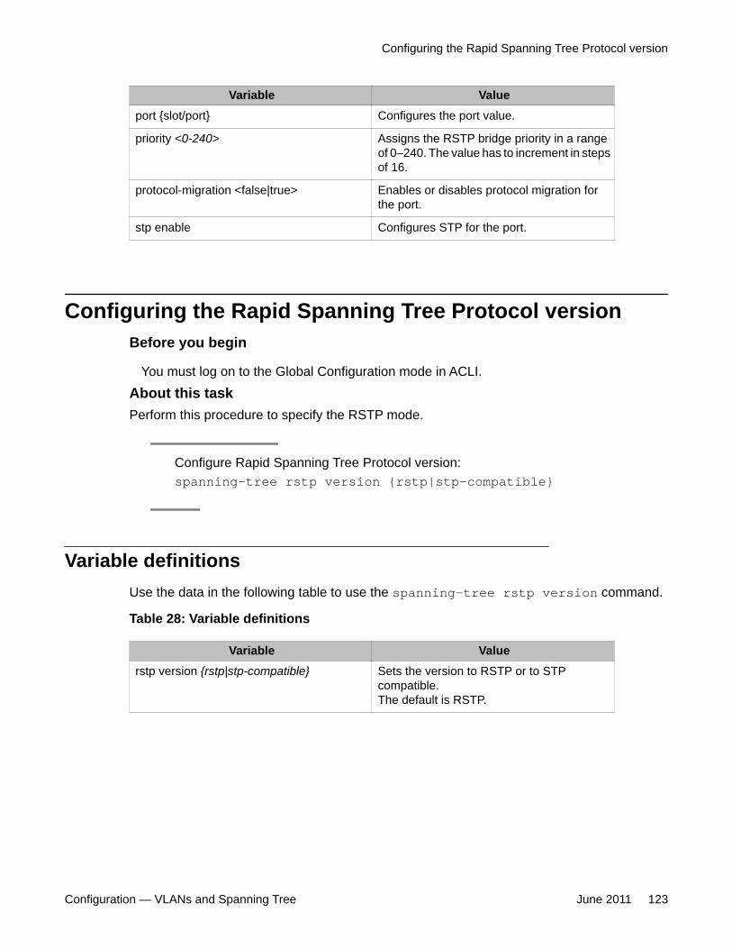
Variable Valueport {slot/port} Configures the port value.
priority <0-240> Assigns the RSTP bridge priority in a rangeof 0–240. The value has to increment in stepsof 16.
protocol-migration <false|true> Enables or disables protocol migration forthe port.
stp enable Configures STP for the port.
Configuring the Rapid Spanning Tree Protocol versionBefore you begin
You must log on to the Global Configuration mode in ACLI.
About this taskPerform this procedure to specify the RSTP mode.
Configure Rapid Spanning Tree Protocol version:spanning-tree rstp version {rstp|stp-compatible}
Variable definitionsUse the data in the following table to use the spanning-tree rstp version command.
Table 28: Variable definitions
Variable Valuerstp version {rstp|stp-compatible} Sets the version to RSTP or to STP
compatible.The default is RSTP.
Configuring the Rapid Spanning Tree Protocol version
Configuration — VLANs and Spanning Tree June 2011 123
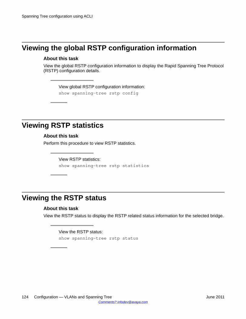
Viewing the global RSTP configuration informationAbout this taskView the global RSTP configuration information to display the Rapid Spanning Tree Protocol(RSTP) configuration details.
View global RSTP configuration information:show spanning-tree rstp config
Viewing RSTP statisticsAbout this taskPerform this procedure to view RSTP statistics.
View RSTP statistics:show spanning-tree rstp statistics
Viewing the RSTP statusAbout this taskView the RSTP status to display the RSTP related status information for the selected bridge.
View the RSTP status:show spanning-tree rstp status
Spanning Tree configuration using ACLI
124 Configuration — VLANs and Spanning Tree June 2011Comments? [email protected]
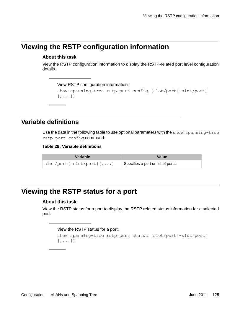
Viewing the RSTP configuration informationAbout this taskView the RSTP configuration information to display the RSTP-related port level configurationdetails.
View RSTP configuration information:show spanning-tree rstp port config [slot/port[-slot/port][,...]]
Variable definitionsUse the data in the following table to use optional parameters with the show spanning-treerstp port config command.
Table 29: Variable definitions
Variable Valueslot/port[-slot/port][,...] Specifies a port or list of ports.
Viewing the RSTP status for a portAbout this taskView the RSTP status for a port to display the RSTP related status information for a selectedport.
View the RSTP status for a port:show spanning-tree rstp port status [slot/port[-slot/port][,...]]
Viewing the RSTP configuration information
Configuration — VLANs and Spanning Tree June 2011 125
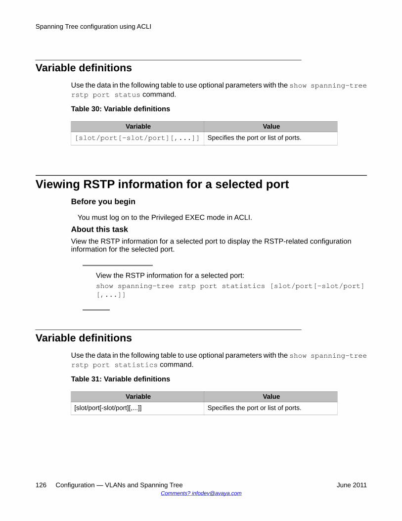
Variable definitionsUse the data in the following table to use optional parameters with the show spanning-treerstp port status command.
Table 30: Variable definitions
Variable Value[slot/port[-slot/port][,...]] Specifies the port or list of ports.
Viewing RSTP information for a selected portBefore you begin
You must log on to the Privileged EXEC mode in ACLI.
About this taskView the RSTP information for a selected port to display the RSTP-related configurationinformation for the selected port.
View the RSTP information for a selected port:show spanning-tree rstp port statistics [slot/port[-slot/port][,...]]
Variable definitionsUse the data in the following table to use optional parameters with the show spanning-treerstp port statistics command.
Table 31: Variable definitions
Variable Value[slot/port[-slot/port][,...]] Specifies the port or list of ports.
Spanning Tree configuration using ACLI
126 Configuration — VLANs and Spanning Tree June 2011Comments? [email protected]
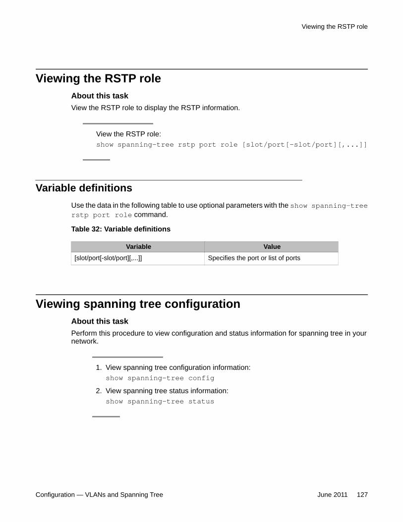
Viewing the RSTP roleAbout this taskView the RSTP role to display the RSTP information.
View the RSTP role:show spanning-tree rstp port role [slot/port[-slot/port][,...]]
Variable definitionsUse the data in the following table to use optional parameters with the show spanning-treerstp port role command.
Table 32: Variable definitions
Variable Value[slot/port[-slot/port][,...]] Specifies the port or list of ports
Viewing spanning tree configurationAbout this taskPerform this procedure to view configuration and status information for spanning tree in yournetwork.
1. View spanning tree configuration information:show spanning-tree config
2. View spanning tree status information:show spanning-tree status
Viewing the RSTP role
Configuration — VLANs and Spanning Tree June 2011 127
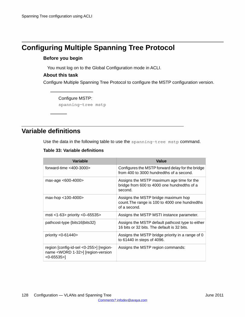
Configuring Multiple Spanning Tree ProtocolBefore you begin
You must log on to the Global Configuration mode in ACLI.
About this taskConfigure Multiple Spanning Tree Protocol to configure the MSTP configuration version.
Configure MSTP:spanning-tree mstp
Variable definitionsUse the data in the following table to use the spanning-tree mstp command.
Table 33: Variable definitions
Variable Valueforward-time <400-3000> Configures the MSTP forward delay for the bridge
from 400 to 3000 hundredths of a second.
max-age <600-4000> Assigns the MSTP maximum age time for thebridge from 600 to 4000 one hundredths of asecond.
max-hop <100-4000> Assigns the MSTP bridge maximum hopcount.The range is 100 to 4000 one hundredthsof a second.
msti <1-63> priority <0–65535> Assigns the MSTP MSTI instance parameter.
pathcost-type {bits16|bits32} Assigns the MSTP default pathcost type to either16 bits or 32 bits. The default is 32 bits.
priority <0-61440> Assigns the MSTP bridge priority in a range of 0to 61440 in steps of 4096.
region [config-id-sel <0-255>] [region-name <WORD 1-32>] [region-version<0-65535>]
Assigns the MSTP region commands:
Spanning Tree configuration using ACLI
128 Configuration — VLANs and Spanning Tree June 2011Comments? [email protected]
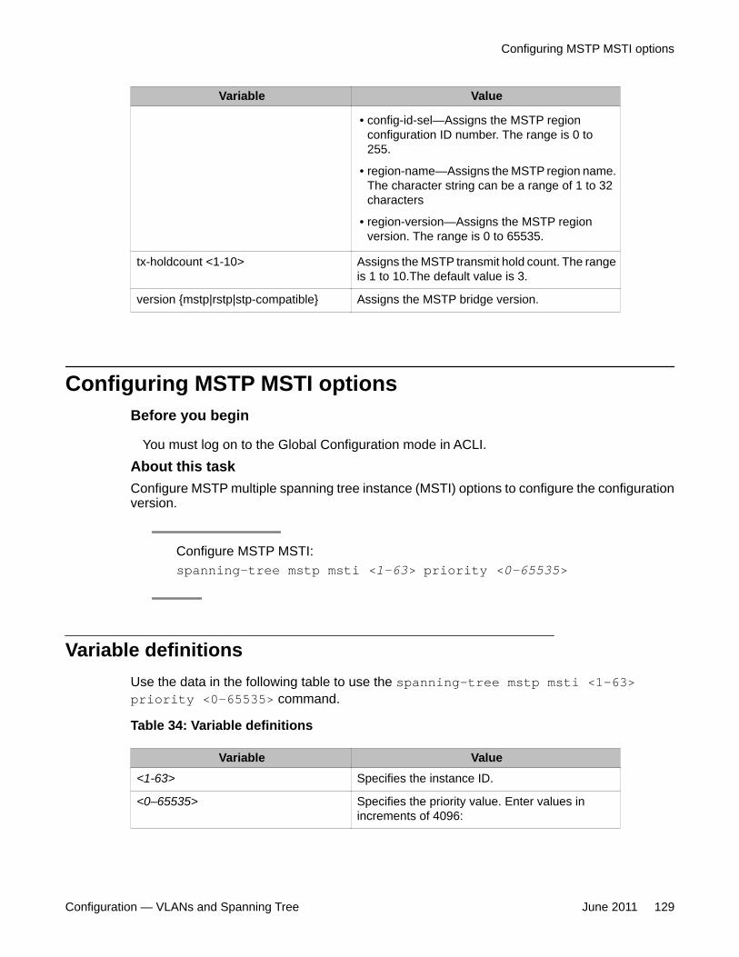
Variable Value
• config-id-sel—Assigns the MSTP regionconfiguration ID number. The range is 0 to255.
• region-name—Assigns the MSTP region name.The character string can be a range of 1 to 32characters
• region-version—Assigns the MSTP regionversion. The range is 0 to 65535.
tx-holdcount <1-10> Assigns the MSTP transmit hold count. The rangeis 1 to 10.The default value is 3.
version {mstp|rstp|stp-compatible} Assigns the MSTP bridge version.
Configuring MSTP MSTI optionsBefore you begin
You must log on to the Global Configuration mode in ACLI.
About this taskConfigure MSTP multiple spanning tree instance (MSTI) options to configure the configurationversion.
Configure MSTP MSTI:spanning-tree mstp msti <1-63> priority <0–65535>
Variable definitionsUse the data in the following table to use the spanning-tree mstp msti <1-63>priority <0–65535> command.
Table 34: Variable definitions
Variable Value<1-63> Specifies the instance ID.
<0–65535> Specifies the priority value. Enter values inincrements of 4096:
Configuring MSTP MSTI options
Configuration — VLANs and Spanning Tree June 2011 129
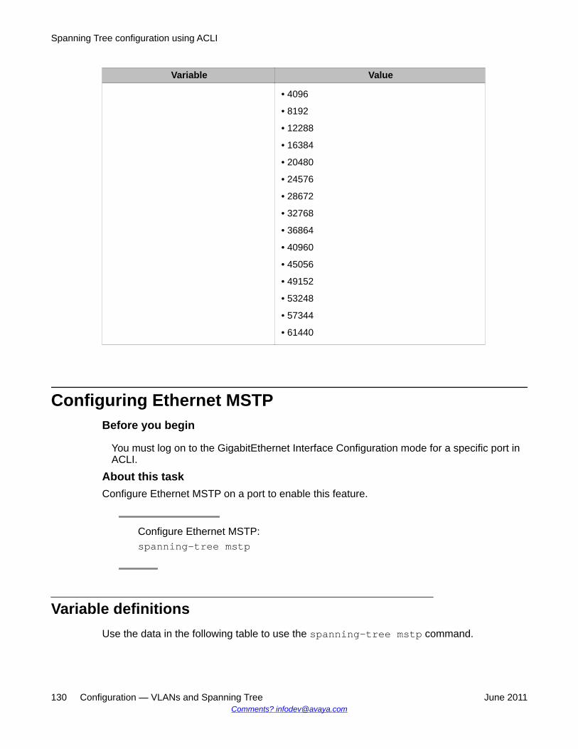
Variable Value
• 4096
• 8192
• 12288
• 16384
• 20480
• 24576
• 28672
• 32768
• 36864
• 40960
• 45056
• 49152
• 53248
• 57344
• 61440
Configuring Ethernet MSTPBefore you begin
You must log on to the GigabitEthernet Interface Configuration mode for a specific port inACLI.
About this taskConfigure Ethernet MSTP on a port to enable this feature.
Configure Ethernet MSTP:spanning-tree mstp
Variable definitionsUse the data in the following table to use the spanning-tree mstp command.
Spanning Tree configuration using ACLI
130 Configuration — VLANs and Spanning Tree June 2011Comments? [email protected]
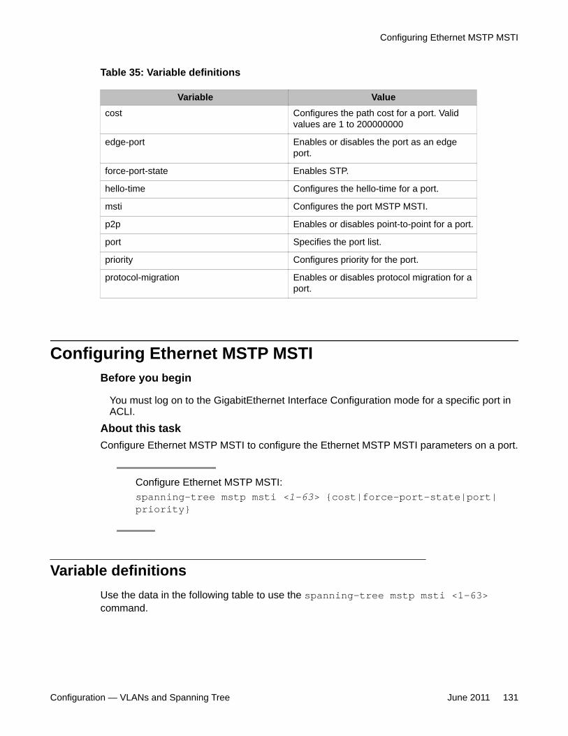
Table 35: Variable definitions
Variable Valuecost Configures the path cost for a port. Valid
values are 1 to 200000000
edge-port Enables or disables the port as an edgeport.
force-port-state Enables STP.
hello-time Configures the hello-time for a port.
msti Configures the port MSTP MSTI.
p2p Enables or disables point-to-point for a port.
port Specifies the port list.
priority Configures priority for the port.
protocol-migration Enables or disables protocol migration for aport.
Configuring Ethernet MSTP MSTIBefore you begin
You must log on to the GigabitEthernet Interface Configuration mode for a specific port inACLI.
About this taskConfigure Ethernet MSTP MSTI to configure the Ethernet MSTP MSTI parameters on a port.
Configure Ethernet MSTP MSTI:spanning-tree mstp msti <1-63> {cost|force-port-state|port|priority}
Variable definitionsUse the data in the following table to use the spanning-tree mstp msti <1-63>command.
Configuring Ethernet MSTP MSTI
Configuration — VLANs and Spanning Tree June 2011 131
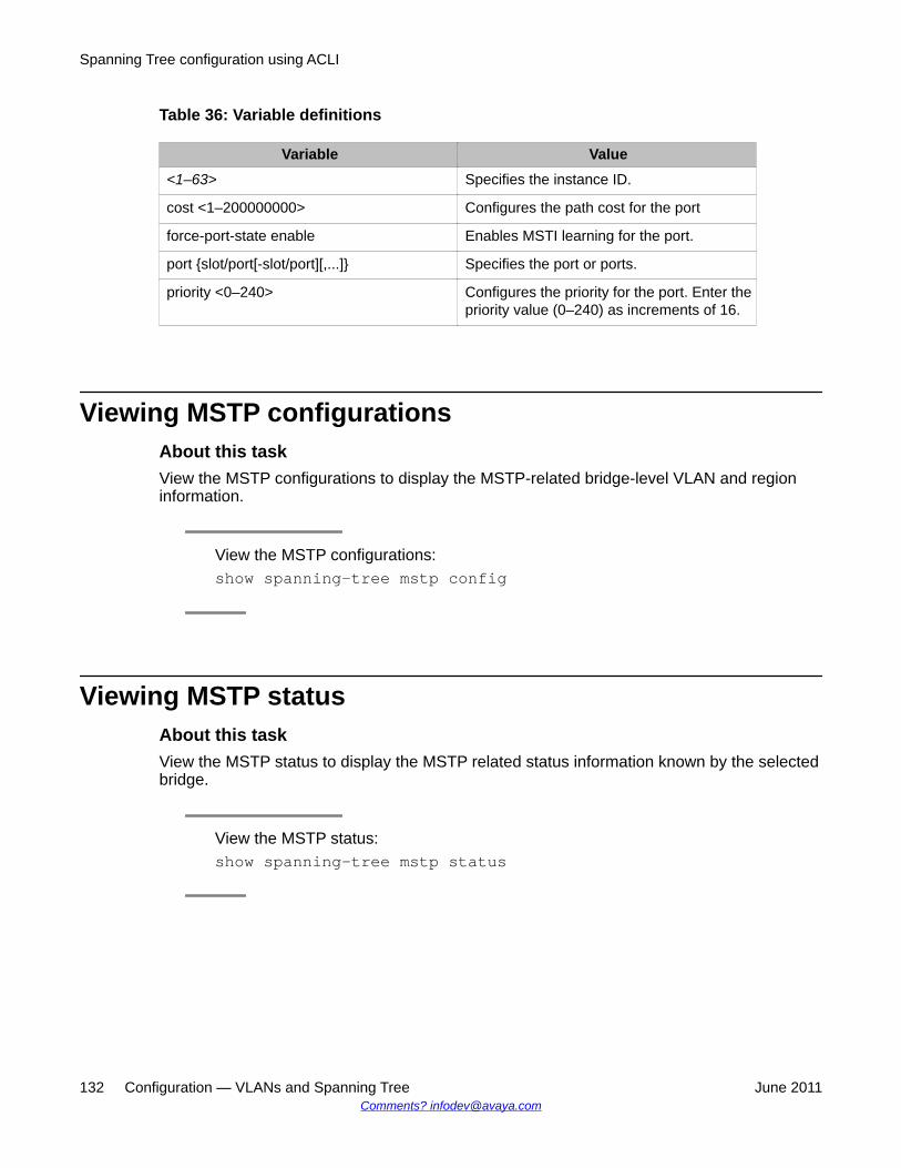
Table 36: Variable definitions
Variable Value<1–63> Specifies the instance ID.
cost <1–200000000> Configures the path cost for the port
force-port-state enable Enables MSTI learning for the port.
port {slot/port[-slot/port][,...]} Specifies the port or ports.
priority <0–240> Configures the priority for the port. Enter thepriority value (0–240) as increments of 16.
Viewing MSTP configurationsAbout this taskView the MSTP configurations to display the MSTP-related bridge-level VLAN and regioninformation.
View the MSTP configurations:show spanning-tree mstp config
Viewing MSTP statusAbout this taskView the MSTP status to display the MSTP related status information known by the selectedbridge.
View the MSTP status:show spanning-tree mstp status
Spanning Tree configuration using ACLI
132 Configuration — VLANs and Spanning Tree June 2011Comments? [email protected]
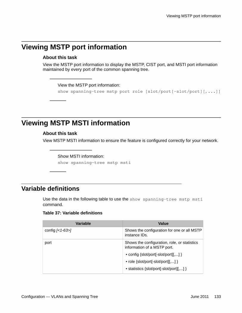
Viewing MSTP port informationAbout this taskView the MSTP port information to display the MSTP, CIST port, and MSTI port informationmaintained by every port of the common spanning tree.
View the MSTP port information:show spanning-tree mstp port role [slot/port[-slot/port][,...]]
Viewing MSTP MSTI informationAbout this taskView MSTP MSTI information to ensure the feature is configured correctly for your network.
Show MSTI information:show spanning-tree mstp msti
Variable definitionsUse the data in the following table to use the show spanning-tree mstp msticommand.
Table 37: Variable definitions
Variable Valueconfig [<1-63>] Shows the configuration for one or all MSTP
instance IDs.
port Shows the configuration, role, or statisticsinformation of a MSTP port.
• config {slot/port[-slot/port][,...] }
• role {slot/port[-slot/port][,...] }
• statistics {slot/port[-slot/port][,...] }
Viewing MSTP port information
Configuration — VLANs and Spanning Tree June 2011 133
Viewing MSTP statisticsAbout this taskView MSTP MSTI information to ensure the feature is configured correctly for your network.
Show MSTP statistics:show spanning-tree mstp statistics
Spanning Tree configuration using ACLI
134 Configuration — VLANs and Spanning Tree June 2011Comments? [email protected]
Chapter 9: Customer service
Visit the Avaya Web site to access the complete range of services and support that Avaya provides. Goto www.avaya.com or go to one of the pages listed in the following sections.
Navigation
• Getting technical documentation on page 135• Getting product training on page 135• Getting help from a distributor or reseller on page 135• Getting technical support from the Avaya Web site on page 136
Getting technical documentationTo download and print selected technical publications and release notes directly from theInternet, go to www.avaya.com/support.
Getting product trainingOngoing product training is available. For more information or to register, you can access theWeb site at www.avaya.com/support. From this Web site, you can locate the Training contactslink on the left-hand navigation pane.
Getting help from a distributor or resellerIf you purchased a service contract for your Avaya product from a distributor or authorizedreseller, contact the technical support staff for that distributor or reseller for assistance.
Configuration — VLANs and Spanning Tree June 2011 135
Getting technical support from the Avaya Web siteThe easiest and most effective way to get technical support for Avaya products is from theAvaya Technical Support Web site at www.avaya.com/support.
Customer service
136 Configuration — VLANs and Spanning Tree June 2011Comments? [email protected]
Index
A
ActiveMembers field ...................................................43AgingTime field ...........................................................52
B
bridging .......................................................................28MAC-layer ............................................................28
brouter port, description .............................................23
C
Color field ...................................................................43configuration ....................................................49, 52, 60
direct broadcast on a VLAN .................................60protocol-based VLAN ...........................................49source MAC-address based VLAN ......................52
customer service ......................................................135
D
directed broadcast ......................................................60distributor ..................................................................135documentation ..........................................................135
F
FdbAging ....................................................................61forwarding database, flushing ....................................65
G
Global MAC filtering ...................................................28
I
IEEE, 802.1Q tagging .................................................20IfIndex field .................................................................54IP routing ..............................................................13, 22
IP protocol-based VLAN ......................................22multicast ...............................................................13source IP subnet-based VLAN .............................22source MAC-based VLAN ....................................22unicast ..................................................................13
IP spoofing .................................................................29
L
loop detection ..................................................30, 59, 90
M
MAC filters ..................................................................28MAC level security ......................................................13MAC-layer bridging .....................................................28MacAddress field .............................................54, 63, 65Monitor field ..........................................................63, 65MSTI Bridges, configuring ........................................114MSTP .........................................................................34MSTP CIST Ports, configuring ..................................111MSTP MSTI Bridges, configuring .............................114MSTP MSTI Ports, configuring .................................116MSTP, configuring globally .......................................108Multicast MAC floodingt ........................................57, 88
N
Name field ..................................................................43Network Load Balancer multicast support ............57, 88Network Load Balancer unicast support ...............57, 88nontagged ports .........................................................20NotAllowToJoin field ...................................................43
P
PID ........................................................................13, 50DSAP value ..........................................................13Ethernet SNAP .....................................................13Ethernet type 2 .....................................................13invalid for user-defined protocol VLAN ...........13, 50
Port field .....................................................................65port-based VLAN ..................................................12, 43
about ....................................................................12create ...................................................................43
PortMembers field ......................................................43Protocol Identifier. See PID ........................................13protocol-based VLAN ............................................13, 49
about ....................................................................13create (Device Manager) .....................................49
ProtocolId field ............................................................43
Configuration — VLANs and Spanning Tree June 2011 137
R
reseller ......................................................................135Result field ..................................................................54RSTP ..........................................................................34RSTP convergence time ............................................34RSTP Edge port .........................................................34RSTP ForceVersion ....................................................34RSTP port status, viewing ........................................106RSTP Ports, configuring ...........................................104RSTP, configuring global parameters .......................102
S
show vlan info commands ..........................................93basic .....................................................................93
source MAC-based VLAN ..........................................52Spanning Tree Groups ...............................................33
with VLANs ..........................................................33Spanning Tree Protocol ............................................127
viewing configuration ..........................................127viewing status .....................................................127
Spanning Tree Protocol. See STP .............................33StaticMembers field ....................................................43Status field ..................................................................63STP ............................................................................33
blocking state .......................................................33bridge protocol data units (BPDUs) .....................33IEEE 802.1D standard .........................................33multiple Spanning Tree Groups ...........................33spanning tree algorithm .......................................33Spanning Tree Groups .........................................33tagged BPDUs .....................................................33
SubnetAddr field .........................................................43SubnetMask field ........................................................43
T
tagged port .................................................................20
training ......................................................................135transit network ............................................................24
U
Untagging Default VLAN on a Tagged Port ................89user-defined protocol-based VLAN ............................13
about ....................................................................13UserDefinedPid field ...................................................54UserPriority field .........................................................54
V
VLAN ....................................................11–13, 20, 22–24configuration rules ................................................24default ..................................................................23enabling tagging ...................................................24ID ....................................................................20, 24IP routing ..............................................................22multiplex traffic .....................................................20policy-based .........................................................13port-based ............................................................12potential member .................................................13protocol-based .....................................................13source IP subnet-based .......................................13source MAC-based ..............................................13spanning multiple switches ..................................11tagged port ...........................................................24timing out .............................................................13untagged port .......................................................24
VLAN bridging .................................................61, 63–66clearing learned MAC addresses by port .............65clearing learned MAC addresses by VLAN ..........64configuring forwarding database timeout .............61static forwarding ...................................................65static multicast .....................................................66viewing forwarding database ...............................63
VlanId field ..................................................................43VLANs .............................................................49, 52, 60
direct broadcast ...................................................60protocol-based .....................................................49source MAC-address based ................................52
VrfId field ....................................................................43VrfName field ..............................................................43
138 Configuration — VLANs and Spanning Tree June 2011