Embed Size (px)
Citation preview

Nortel Ethernet Routing Switch 5000 Series
Configuration — VLANs,Spanning Tree, and LinkAggregationRelease: 6.1Document Revision: 05.02
www.nortel.com
NN47200-502.

Nortel Ethernet Routing Switch 5000 SeriesRelease: 6.1Publication: NN47200-502Document release date: 17 February 2010
Copyright © 2005-2010 Nortel Networks. All Rights Reserved.
While the information in this document is believed to be accurate and reliable, except as otherwise expresslyagreed to in writing NORTEL PROVIDES THIS DOCUMENT "AS IS" WITHOUT WARRANTY OR CONDITION OFANY KIND, EITHER EXPRESS OR IMPLIED. The information and/or products described in this document aresubject to change without notice.
Nortel, Nortel Networks, the Nortel logo, and the Globemark are trademarks of Nortel Networks.
All other trademarks are the property of their respective owners.
.

3.
ContentsNew in this Release 13Features 13
VLACP enhancements 13
Introduction 15NNCLI command modes 15
VLAN Fundamentals 17Virtual Local Area Networks (VLAN) 17
IEEE 802.1Q Tagging 18VLANs Spanning Multiple Switches 24VLAN Summary 27VLAN Configuration Rules 28
VLAN Configuration Control 29Multinetting 30
Spanning Tree Protocol Fundamentals 31Spanning Tree Protocol groups 31
STG Configuration Guidelines 32Spanning Tree Fast Learning 34STG port membership mode 34802.1t path cost calculation 35
Rapid Spanning Tree Protocol 35Multiple Spanning Tree Protocol 35
Interoperability with legacy STP 36Differences in STP and RSTP port roles 36Rapid convergent 37
Spanning Tree BPDU Filtering 39Configuring Spanning Tree using the Console Interface 41
Spanning Tree configuration in STPG mode 41Spanning Tree configuration in RSTP mode 50Spanning Tree configuration in MSTP mode 57Spanning Tree VLAN Membership screen in MSTP mode 65
Multi-Link Trunking Fundamentals 67Multi-Link trunks 67
Nortel Ethernet Routing Switch 5000 SeriesConfiguration — VLANs, Spanning Tree, and Link Aggregation
NN47200-502 05.02 17 February 2010
Copyright © 2005-2010 Nortel Networks. All Rights Reserved.
.

4
Client-server configuration using Multi-Link trunks 67Before configuring trunks 68Multi-Link Trunking Configuration Rules 69Adding and deleting links from existing Multi-Link trunks 71How a Multi-Link trunk reacts to losing distributed trunk members 71Spanning Tree Considerations for Multi-Link trunks 72Port membership in Multi-Link Trunking 75
SMLT 76Overview 76Advantages of SMLT 77How does SMLT work? 78SLT 104Using SMLT with SLT 105SMLT and SLT Configuration steps 107SLPP 121
IEEE 802.3ad Link Aggregation 121Link aggregation rules 123LACP port mode 124
VLACP Fundamentals 125VLACP 125
Virtual LACP (VLACP) overview 125VLACP features 127
ADAC Fundamentals 129ADAC operation 130
Auto-Detection of Nortel IP Phones 130Auto-Detection by MAC address 131Auto-Detection by LLDP (IEEE 802.1ab) 132Auto-Configuration of Nortel IP Phones 133Initial user settings 134Operating modes 136ADAC and stacking 141ADAC and LACP enabled on an Uplink port 142ADAC and EAP configuration 143ADAC user Restrictions 143
Configuring VLANs using the NNCLI 145Creating and Managing VLANs using the NNCLI 145
Displaying VLAN information 145Displaying VLAN interface information 147Displaying VLAN port membership 147Setting the management VLAN 147Resetting the management VLAN to default 147Creating a VLAN 148
Nortel Ethernet Routing Switch 5000 SeriesConfiguration — VLANs, Spanning Tree, and Link Aggregation
NN47200-502 05.02 17 February 2010
Copyright © 2005-2010 Nortel Networks. All Rights Reserved.
.

5
Deleting a VLAN 149Modifying VLAN MAC address flooding 149Configuring VLAN name 150Enabling automatic PVID 150Configuring VLAN port settings 150Configuring VLAN members 151Configuring VLAN Configuration Control 152Managing the MAC address forwarding database table 154IP Directed Broadcasting 157
Configuring STP using the NNCLI 159Setting the STP mode using the NNCLI 159
Procedure steps 159Configuring STP BPDU Filtering using the NNCLI 159
Procedure steps 159Variable definitions 160
Creating and Managing STGs using the NNCLI 160Configuring path cost calculation mode 161Configuring STG port membership mode 161Displaying STP configuration information 161Creating a Spanning Tree Group 162Deleting a Spanning Tree Group 162Enabling a Spanning Tree Group 163Disabling a Spanning Tree Group 163Configuring STP values 163Restoring default Spanning Tree values 165Adding a VLAN to a STG 165Removing a VLAN from a STG 166Configuring STP and MSTG participation 166Resetting Spanning Tree values for ports to default 167
Managing RSTP using the NNCLI 168Configuring RSTP parameters 168Configuring RSTP on a port 169Displaying RSTP configuration 170Displaying RSTP port configuration 171
Managing MSTP using the NNCLI 171Configuring MSTP parameters 172Configuring MSTP on a port 173Configuring MSTP region parameters 174Configuring MSTP parameters 174Disabling a MSTP bridge instance 175Deleting a MSTP bridge instance 175Displaying MSTP status 176Displaying MSTP Cist port information 176
Nortel Ethernet Routing Switch 5000 SeriesConfiguration — VLANs, Spanning Tree, and Link Aggregation
NN47200-502 05.02 17 February 2010
Copyright © 2005-2010 Nortel Networks. All Rights Reserved.
.

6
Displaying MSTP MSTI settings 177
Configuring MLT using the NNCLI 179Displaying MLT configuration and utilization 179
Procedure steps 179Configuring a Multi-Link trunk 179
Procedure steps 179Variable definitions 180
Disabling a MLT 180Procedure steps 180
Displaying MLT properties 180Procedure steps 180
Configuring STP participation for MLTs 181Procedure steps 181Variable definitions 181
Configuring SMLT using the NNCLI 181Setting command mode to MLT Interface mode 182Creating a SMLT 182Creating a IST 183Creating a SLT on a port 184Disabling SMLT 184DIsabling IST 184Disabling a SLT on a port 185Resetting SMLT to default 185Resetting a IST to default 186Resetting a SMLT to default 186Displaying IST parameters 186Displaying IST statistics 187Displaying SLT and SMLT configurations 187
Configuring SLPP using the NNCLI 187Configuring SLPP transmitting list 188Enabling SLPP 188Configuring SLPP PDU transmit interval 188Configuring SLPP PDU ether type 189Configuring SLPP port auto enable 189Enabling SLPP PDU receive function per port 189Configuring the SLPP PDU receipt threshold 190
Troubleshooting IST problems 190Procedure steps 190
Configuring LACP and VLACP using the NNCLI 193Configuring Link Aggregation using the NNCLI 193
Displaying LACP system settings 194Displaying LACP per port configuration 194Displaying LACP port mode 194
Nortel Ethernet Routing Switch 5000 SeriesConfiguration — VLANs, Spanning Tree, and Link Aggregation
NN47200-502 05.02 17 February 2010
Copyright © 2005-2010 Nortel Networks. All Rights Reserved.
.

7
Displaying LACP port statistics 195Clearing LACP port statistics 195Displaying LACP port debug information 195Displaying LACP aggregators 196Configuring LACP system priority 196Enabling LACP port aggregation mode 196Configuring the LACP administrative key 197Configuring LACP operating mode 197Configuring per port LACP priority 198Configuring LACP periodic transmission timeout interval 199Configuring LACP port mode 199
Configuring VLACP using the NNCLI 200Enabling VLACP globally 200Configuring VLACP multicast MAC address 200Configuring VLACP port parameters 201Displaying VLACP status 203Displaying VLACP port configuration 204
Configuring ADAC using the NNCLI 205Configuring ADAC for Nortel IP Phones using the NNCLI 205
Configuring global ADAC settings 205Restoring default ADAC settings 206Configuring ADAC per port settings 207Resetting ADAC per port settings to default 208Configuring autodetection method 208Resetting autodetection method to default 209Configuring autodetection for ports 210Restoring ADAC port settings 210Adding a range to ADAC MAC address table 210Restoring ADAC MAC range table 211Displaying global ADAC settings 211Displaying ADAC port settings 211Displaying ADAC MAC ranges 212Displaying configured detection mechanism 212ADAC UFA configuration example 213ADAC configuration commands 214Verifying new ADAC settings 214
Configuring VLANs using Device Manager 217Configuring VLAN settings 218
Procedure steps 218Variable definitions 219
Enabling AutoPVID 219Procedure steps 220
Creating a VLAN 220
Nortel Ethernet Routing Switch 5000 SeriesConfiguration — VLANs, Spanning Tree, and Link Aggregation
NN47200-502 05.02 17 February 2010
Copyright © 2005-2010 Nortel Networks. All Rights Reserved.
.

8
Procedure steps 220Modifying a VLAN 221
Procedure steps 221Deleting VLANs 221
Procedure steps 222Procedure steps 222Variable definitions 222
Configuring IGMP snooping 223Assigning an IP address to a VLAN 223
Prerequisites 223Procedure steps 224Variable definitions 224
Configuring the IP multicast filter table 224Procedure steps 225
Configuring VLAN DHCP 225Prerequisites 225Procedure steps 225Variable definitions 226
Clearing DHCP statistics counters on a VLAN 226Procedure steps 226
Graphing DHCP statistics 226Procedure steps 227Variable definitions 227
Configuring NSNA per VLAN 227Procedure steps 227Variable definitions 228
Deleting an NSNA VLAN 228Prerequisites 228Procedure steps 228
Filtering an NSNA VLAN 229Procedure steps 229
MAC address table maintenance using the Device Manager 230Flushing the MAC address table 230
Configuring STP using Device Manager 231Setting the STP mode using Device Manager 231
Procedure steps 231Configuring STP BPDU Filtering using Device Manager 231
Procedure steps 232Variable definitions 232
Creating and Managing STGs using Device Manager 232Configuring STG global properties 233Creating an STG 234Adding a VLAN to an STG 235
Nortel Ethernet Routing Switch 5000 SeriesConfiguration — VLANs, Spanning Tree, and Link Aggregation
NN47200-502 05.02 17 February 2010
Copyright © 2005-2010 Nortel Networks. All Rights Reserved.
.
9
Moving a VLAN between STGs 236Deleting an STG 236Displaying STG Status 236Displaying STG ports 237Configuring RSTP using Device Manager 240Configuring MSTP using Device Manager 246
Configuring MLT using Device Manager 259Setting up MLTs 259
Procedure steps 259Variable definitions 259Filtering the Multi-Link Trunks tab display 260
Adding MLT Ports 261Procedure steps 261
Configuring SMLT using Device Manager 261Adding an MLT-based SMLT 262Viewing SLTs configured on your switch 263Configuring an IST MLT 264Removing an IST MLT 265Viewing IST statistics 265Graphing MLT interface statistics 267Graphing MLT ethernet error statistics 267Configuring an SLT 268Deleting an SLT 269
Configuring SLPP using Device Manager 269Configuring SLPP transmitting list 270Enabling SLPP 270Configuring SLPP PDU transmit interval 270Configuring SLPP PDU ether type 271Configuring SLPP port auto enable 271Enabling SLPP PDU received function per port 272Configuring the SLPP PDU receipt threshold 272
Configuring LACP and VLACP using Device Manager 275Configuring LACP using Device Manager 275
LACP Global tab 275LACP tab 276LACP tab for ports 277
Configuring VLACP using Device Manager 279VLACP Global tab 279VLACP tab for ports 280
Configuring ADAC using Device Manager 283Procedure steps 283Variable definitions 283
Nortel Ethernet Routing Switch 5000 SeriesConfiguration — VLANs, Spanning Tree, and Link Aggregation
NN47200-502 05.02 17 February 2010
Copyright © 2005-2010 Nortel Networks. All Rights Reserved.
.

10
Procedure steps 284Deleting MAC address ranges using Device Manager 285Configuring ADAC settings on a port 285
Configuring VLANs using Web based management 289Creating and Managing VLANs using Web-based Management 289
Creating a Port-based VLAN 289Creating a Protocol-based VLAN 290Modifying a Port-based VLAN 294Modifying a Protocol-based VLAN 295Selecting a Management VLAN 296Deleting a VLAN configuration 296
Flushing the MAC address table using Web-based management 297Procedure steps 297Variable definitions 298
Configuring STP using Web based management 299Setting the STP mode using Web-based Management 299
Procedure steps 299Creating and Managing STGs using Web-based Management 299
Creating a Spanning Tree Group 300Modifying a Spanning Tree Group 301Deleting a Spanning Tree Group 301Associating an STG with VLAN Membership 302Spanning Tree Port Configuration 303Modifying STG Bridge Information 304
Configuring RSTP using Web-based management 306Configuring RSTP bridge settings 306Configuring RSTP port settings 308
Configuring MSTP using Web-based management 309Creating MSTI instances 309Configuring MSTI bridge settings 310Configuring CIST bridge settings 311Adding VLANs to the MSTI 312Configuring Cist ports 313Configuring MSTI port properties 314
Configuring MLT using Web based management 317Creating a Multi-Link trunk 317
Procedure steps 317Variable definitions 317
Configuring Spanning Tree Group Participation 318Procedure steps 318
Monitoring an MLT 319Procedure steps 319
Nortel Ethernet Routing Switch 5000 SeriesConfiguration — VLANs, Spanning Tree, and Link Aggregation
NN47200-502 05.02 17 February 2010
Copyright © 2005-2010 Nortel Networks. All Rights Reserved.
.

11
Configuring ADAC using Web based Management 321Configuring global ADAC properties 321
Procedure steps 321Variable definitions 322
Configuring ADAC port properties 322Procedure steps 322
Configuring ADAC MAC address ranges 323Procedure steps 323Variable definitions 323
Configuring ADAC Port Detection 324Procedure steps 324Variable definitions 324
Configuring LACP using Web based management 325Bridge Configuration page 325
Procedure steps 325Variable definitions 325
Port Configuration page 325Procedure steps 326Variable definitions 326
Port Statistics page 326Procedure steps 326Variable definitions 327
Nortel Ethernet Routing Switch 5000 SeriesConfiguration — VLANs, Spanning Tree, and Link Aggregation
NN47200-502 05.02 17 February 2010
Copyright © 2005-2010 Nortel Networks. All Rights Reserved.
.

12
Nortel Ethernet Routing Switch 5000 SeriesConfiguration — VLANs, Spanning Tree, and Link Aggregation
NN47200-502 05.02 17 February 2010
Copyright © 2005-2010 Nortel Networks. All Rights Reserved.
.

13.
New in this ReleaseThe following sections detail what’s new in Nortel Ethernet Routing Switch5000 Configuration — VLANs, Spanning Tree and Link Aggregation(NN47200-502):
FeaturesSee the following sections for information about feature changes:
• “VLACP enhancements” (page 13)
VLACP enhancementsSeveral enhancements have been made to the functioning of VLACP. Formore information, see:
• “VLACP features” (page 127)
Nortel Ethernet Routing Switch 5000 SeriesConfiguration — VLANs, Spanning Tree, and Link Aggregation
NN47200-502 05.02 17 February 2010
Copyright © 2005-2010 Nortel Networks. All Rights Reserved.
.

14 New in this Release
Nortel Ethernet Routing Switch 5000 SeriesConfiguration — VLANs, Spanning Tree, and Link Aggregation
NN47200-502 05.02 17 February 2010
Copyright © 2005-2010 Nortel Networks. All Rights Reserved.
.

15.
IntroductionThis document provides information you need to configure VLANs,Spanning Tree and Link Aggregation for the Ethernet Routing Switch 5000Series.
NNCLI command modesNNCLI provides the following command modes:
• User EXEC
• Privileged EXEC
• Global Configuration
• Interface Configuration
• Router Configuration
Mode access is determined by access permission levels and passwordprotection.
If no password is set, you can enter NNCLI in User EXEC mode and usethe enable command to move to the next level (Privileged EXEC mode).However, if you have read-only access, you cannot progress beyond UserEXEC mode, the default mode. If you have read-write access you canprogress from the default mode through all of the available modes.
With sufficient permission, you can use the rules in the following table tomove between the command modes.
Command mode and sampleprompt
Entrance commands Exit commands
User EXEC
5650TD>
No entrance command, defaultmode
exit
orlogout
Privileged EXEC
5650TD#
enable exit
orlogout
Nortel Ethernet Routing Switch 5000 SeriesConfiguration — VLANs, Spanning Tree, and Link Aggregation
NN47200-502 05.02 17 February 2010
Copyright © 2005-2010 Nortel Networks. All Rights Reserved.
.

16 Introduction
Command mode and sampleprompt
Entrance commands Exit commands
Global Configuration
5650TD(config)#
configure To return to Privileged EXECmode, enter:
end
orexit
To exit NNCLI completely,enter:
logout
Interface Configuration
5650TD(config-if)#
From Global Configurationmode:To configure a port, enter:
interface fastethernet<port number>
To configure a VLAN, enter:
interface vlan <vlannumber>
To return to GlobalConfiguration mode, enter:
exit
To return to Privileged EXECmode, enter:
end
To exit NNCLI completely,enter:
logout
Router Configuration
5650TD (config-router)#
From Global Configurationmode, to configure OSPF,enter:
router ospf
To configure RIP, enter:
router rip
To configure VRRP, enter:
router vrrp
To return to GlobalConfiguration mode, enter:
exit
To return to Privileged EXECmode, enter:
end
To exit NNCLI completely,enter:
logout
See Nortel Ethernet Routing Switch 5000 Series FundamentalsNN47200-104
Nortel Ethernet Routing Switch 5000 SeriesConfiguration — VLANs, Spanning Tree, and Link Aggregation
NN47200-502 05.02 17 February 2010
Copyright © 2005-2010 Nortel Networks. All Rights Reserved.
.

17.
VLAN Fundamentals
Virtual Local Area Networks (VLAN)The Nortel Ethernet Routing Switch 5000 Series supports up to 256VLANs.
Ports are grouped into broadcast domains by assigning them to the sameVLAN. Frames received in one VLAN can only be forwarded within thatVLAN, and multicast frames and unknown unicast frames are flooded onlyto ports in the same VLAN.
Setting up virtual LANs (VLAN) is a way to segment networks to increasenetwork capacity and performance without changing the physicalnetwork topology (Figure 1 "Port-based VLAN" (page 17)). With networksegmentation, each switch port connects to a segment that is a singlebroadcast domain. When you configure a switch port to be a member ofa VLAN, you add it to a group of ports (workgroup) that belong to onebroadcast domain.
Figure 1Port-based VLAN
Nortel Ethernet Routing Switch 5000 SeriesConfiguration — VLANs, Spanning Tree, and Link Aggregation
NN47200-502 05.02 17 February 2010
Copyright © 2005-2010 Nortel Networks. All Rights Reserved.
.

18 VLAN Fundamentals
The Nortel Ethernet Routing Switch 5000 Series allows ports to beassigned to VLANs using the Command Line Interface, Web-basedManagement, or Device Manager. Different ports (and there devices) canbe assigned to different broadcast domains. This feature provides networkflexibility because VLANs can be reassigned to accommodate networkmoves, additions, and changes, eliminating the need to change physicalcabling.
IEEE 802.1Q TaggingThe Nortel Ethernet Routing Switch 5000 Series operates in accordancewith the IEEE 802.1Q tagging rules. Important terms used with the 32-bit802.1Q tagging feature are:
• VLAN identifier (VID) -- the 12-bit portion of the VLAN tag in the frameheader that identifies an explicit VLAN. When other types of VLANs areenabled, this default value can be overridden by the values enabled inthe management interfaces.
• Port VLAN identifier (PVID) -- a classification mechanism thatassociates a port with a specific VLAN. For example, a port with aPVID of 3 (PVID =3) assigns all untagged frames received on this portto VLAN 3.
• Tagged frame -- a frame that contains the 32-bit 802.1q field (VLANtag). This field identifies the frame as belonging to a specific VLAN.
• Untagged frame -- a frame that does not carry any VLAN tagginginformation in the frame header.
• VLAN port members -- a group of ports that are all members of aparticular VLAN. A port can be a member of one or more VLANs.
• Untagged member -- a port that has been configured as an untaggedmember of a specific VLAN. When an untagged frame exits theswitch through an untagged member port, the frame header remainsunchanged. When a tagged frame exits the switch through anuntagged member port, the tag is stripped and the tagged frame ischanged to an untagged frame.
• Tagged member -- a port that has been configured as a taggedmember of a specific VLAN. When an untagged frame exits the switchthrough a tagged member port, the frame header is modified to includethe 32-bit tag associated with the ingress port PVID. When a taggedframe exits the switch through a tagged member port, the frameheader remains unchanged (original VID remains).
• User priority -- a three-bit field in the header of a tagged frame. Thefield is interpreted as a binary number, therefore has a value of 0 -7. This field allows the tagged frame to carry the user-priority across
Nortel Ethernet Routing Switch 5000 SeriesConfiguration — VLANs, Spanning Tree, and Link Aggregation
NN47200-502 05.02 17 February 2010
Copyright © 2005-2010 Nortel Networks. All Rights Reserved.
.

Virtual Local Area Networks (VLAN) 19
bridged LANs where the individual LAN segments may be unable tosignal priority information.
• Port priority -- the priority level assigned to untagged frames receivedon a port. This value becomes the user priority for the frame. Taggedpackets get their user priority from the value contained in the 32-bit802.1Q frame header.
• Unregistered packet -- a tagged frame that contains a VID where thereceiving port is not a member of that VLAN.
• Filtering database identifier (FID) -- the specific filtering/forwardingdatabase within the Nortel Ethernet Routing Switch 5000 Seriesswitch that is assigned to each VLAN. Each VLAN has its own filteringdatabase, which is called independent VLAN learning (IVL). IVLs canhave duplicate MAC addresses in different VLANs.
The default configuration settings for the Nortel Ethernet Routing Switch5000 Series have all ports set as untagged members of VLAN 1 with allports configured as PVID = 1. Every VLAN is assigned a unique VLANidentifier (VID) that distinguishes it from all other VLANs. In the defaultconfiguration example shown in Figure 2 "Default VLAN Settings" (page20), all incoming packets are assigned to VLAN 1 by the default portVLAN identifier (PVID =1). Untagged packets enter and leave the switchunchanged.
Nortel Ethernet Routing Switch 5000 SeriesConfiguration — VLANs, Spanning Tree, and Link Aggregation
NN47200-502 05.02 17 February 2010
Copyright © 2005-2010 Nortel Networks. All Rights Reserved.
.

20 VLAN Fundamentals
Figure 2Default VLAN Settings
Switch ports can be configured to transmit frames tagged on some VLANs,and untagged on other VLANs.
When VLANs are configured, the egress tagging of each switch port canbe configured as Untag All, Untag PVID Only, Tag All or Tag PVID Only.
In Figure 3 "Port-based VLAN assignment" (page 20), untagged incomingpackets are assigned directly to VLAN 2 (PVID = 2). Port 5 is configuredas a tagged member of VLAN 2, and port 7 is configured as an untaggedmember of VLAN 2.
Figure 3Port-based VLAN assignment
Nortel Ethernet Routing Switch 5000 SeriesConfiguration — VLANs, Spanning Tree, and Link Aggregation
NN47200-502 05.02 17 February 2010
Copyright © 2005-2010 Nortel Networks. All Rights Reserved.
.

Virtual Local Area Networks (VLAN) 21
As shown in Figure 4 "802.1Q tagging (after port-based VLANassignment)" (page 21), the untagged packet is marked (tagged) as itleaves the switch through port 5, which is configured as a tagged memberof VLAN 2. The untagged packet remains unchanged as it leaves theswitch through port 7, which is configured as an untagged member ofVLAN 2.
Figure 4802.1Q tagging (after port-based VLAN assignment)
In Figure 5 "Protocol-based VLAN assignment" (page 21), untaggedincoming packets are assigned to VLAN 3 (protocol-based VLAN = 3,PVID = 2). Port 5 is configured as a tagged member of VLAN 3, and port 7is configured as an untagged member of VLAN 3.
Figure 5Protocol-based VLAN assignment
As shown in Figure 6 "802.1Q tagging (after protocol-based VLANassignment)" (page 22), the untagged packet is marked (tagged) as itleaves the switch through port 5, which is configured as a tagged memberof VLAN 3. The untagged packet remains unchanged as it leaves theswitch through port 7, which is configured as an untagged member ofVLAN 3.
Nortel Ethernet Routing Switch 5000 SeriesConfiguration — VLANs, Spanning Tree, and Link Aggregation
NN47200-502 05.02 17 February 2010
Copyright © 2005-2010 Nortel Networks. All Rights Reserved.
.

22 VLAN Fundamentals
Figure 6802.1Q tagging (after protocol-based VLAN assignment)
In Figure 7 "802.1Q tag assignment" (page 22), tagged incoming packetsare assigned directly to VLAN 2 because of the tag assignment in thepacket. Port 5 is configured as a tagged member of VLAN 2, and port 7 isconfigured as an untagged member of VLAN 2.
Figure 7802.1Q tag assignment
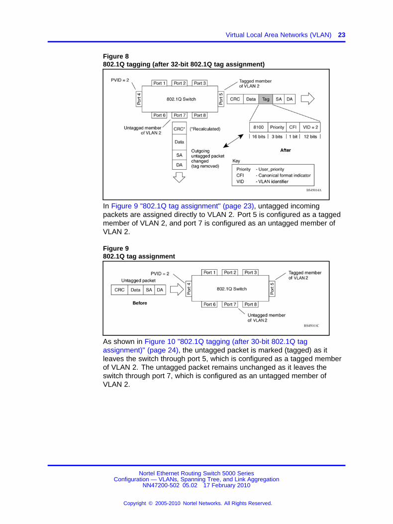
As shown in Figure 8 "802.1Q tagging (after 32-bit 802.1Q tagassignment)" (page 23), the tagged packet remains unchanged as it leavesthe switch through port 5, which is configured as a tagged member ofVLAN 2. However, the tagged packet is stripped (untagged) as it leavesthe switch through port 7, which is configured as an untagged memberof VLAN 2.
Nortel Ethernet Routing Switch 5000 SeriesConfiguration — VLANs, Spanning Tree, and Link Aggregation
NN47200-502 05.02 17 February 2010
Copyright © 2005-2010 Nortel Networks. All Rights Reserved.
.
Virtual Local Area Networks (VLAN) 23
Figure 8802.1Q tagging (after 32-bit 802.1Q tag assignment)
In Figure 9 "802.1Q tag assignment" (page 23), untagged incomingpackets are assigned directly to VLAN 2. Port 5 is configured as a taggedmember of VLAN 2, and port 7 is configured as an untagged member ofVLAN 2.
Figure 9802.1Q tag assignment
As shown in Figure 10 "802.1Q tagging (after 30-bit 802.1Q tagassignment)" (page 24), the untagged packet is marked (tagged) as itleaves the switch through port 5, which is configured as a tagged memberof VLAN 2. The untagged packet remains unchanged as it leaves theswitch through port 7, which is configured as an untagged member ofVLAN 2.
Nortel Ethernet Routing Switch 5000 SeriesConfiguration — VLANs, Spanning Tree, and Link Aggregation
NN47200-502 05.02 17 February 2010
Copyright © 2005-2010 Nortel Networks. All Rights Reserved.
.

24 VLAN Fundamentals
Figure 10802.1Q tagging (after 30-bit 802.1Q tag assignment)
VLANs Spanning Multiple SwitchesVLANs can be used to segment a network within a switch. When multipleswitches are connected, you can connect users of one VLAN with users ofthat same VLAN in another switch. However, the configuration guidelinesdepend on whether both switches support 32-bit 802.1Q tagging.
With 32-bit 802.1Q tagging enabled on a port for a VLAN, all framesleaving the port for that VLAN are marked as belonging to that specificVLAN. Specific switch ports can be assigned as members of one or moreVLANs that span multiple switches, without interfering with the SpanningTree Protocol.
VLANs spanning multiple 802.1Q tagged switchesFigure 11 " VLANs spanning multiple 802.1Q tagged switches" (page25) shows VLANs spanning two Nortel Ethernet Routing Switch 5000Series switches. The 32-bit 802.1Q tagging is enabled on S1, port 14 andon S2, port 13 for VLAN 1 and VLAN 2. Both ports are tagged members ofVLAN 1 and VLAN 2.
Nortel Ethernet Routing Switch 5000 SeriesConfiguration — VLANs, Spanning Tree, and Link Aggregation
NN47200-502 05.02 17 February 2010
Copyright © 2005-2010 Nortel Networks. All Rights Reserved.
.

Virtual Local Area Networks (VLAN) 25
Figure 11VLANs spanning multiple 802.1Q tagged switches
Because only one link exists between the two switches, the SpanningTree Protocol (STP) treats this configuration as any other switch-to-switchconnection. For this configuration to work properly, both switches mustsupport the 32-bit 802.1Q tagging protocol.
VLANS spanning multiple untagged switchesFigure 12 "VLANs spanning multiple untagged switches" (page 26) showsVLANs spanning multiple untagged switches. In this configuration, SwitchS2 does not support 32-bit 802.1Q tagging and you must use a singleswitch port on each switch for each VLAN.
For this configuration to work properly, you must set spanning treeparticipation to Disabled (the STP is not supported across multiple LANs).
Nortel Ethernet Routing Switch 5000 SeriesConfiguration — VLANs, Spanning Tree, and Link Aggregation
NN47200-502 05.02 17 February 2010
Copyright © 2005-2010 Nortel Networks. All Rights Reserved.
.

26 VLAN Fundamentals
Figure 12VLANs spanning multiple untagged switches
When the STP is enabled on these switches, only one link between thepair of switches forwards traffic. Because each port belongs to only oneVLAN at a time, connectivity on the other VLAN is lost. Exercise carewhen configuring the switches to ensure that the VLAN configuration doesnot conflict with spanning tree configuration.
To connect multiple VLANs across switches with redundant links, youmust disable the STP on all participating switch ports. Figure 13 "Possibleproblems with VLANs and Spanning Tree Protocol" (page 27) showspossible consequences of enabling the STP when using VLANs betweenuntagged (non-802.1Q tagged) switches.
Nortel Ethernet Routing Switch 5000 SeriesConfiguration — VLANs, Spanning Tree, and Link Aggregation
NN47200-502 05.02 17 February 2010
Copyright © 2005-2010 Nortel Networks. All Rights Reserved.
.

Virtual Local Area Networks (VLAN) 27
Figure 13Possible problems with VLANs and Spanning Tree Protocol
As shown in Figure 13 "Possible problems with VLANs and Spanning TreeProtocol" (page 27), with STP enabled, only one connection betweenSwitch S1 and Switch S2 is forwarding at any time. Communicationsfailure occurs between VLAN 2 of S1 and VLAN 2 of S2, blockingcommunications between Stations A and B.
The STP selects the link connecting VLAN 1 on Switches S1 and S2 asthe forwarding link based on port speed, duplex-mode, and port priority.Because the other link connecting VLAN 2 is in Blocking mode, stationson VLAN 2 in Switch S1 cannot communicate with stations in VLAN 2 onSwitch S2. With multiple links only one link will be forwarding.
VLAN SummaryThis section summarizes the VLAN examples discussed in the previoussections.
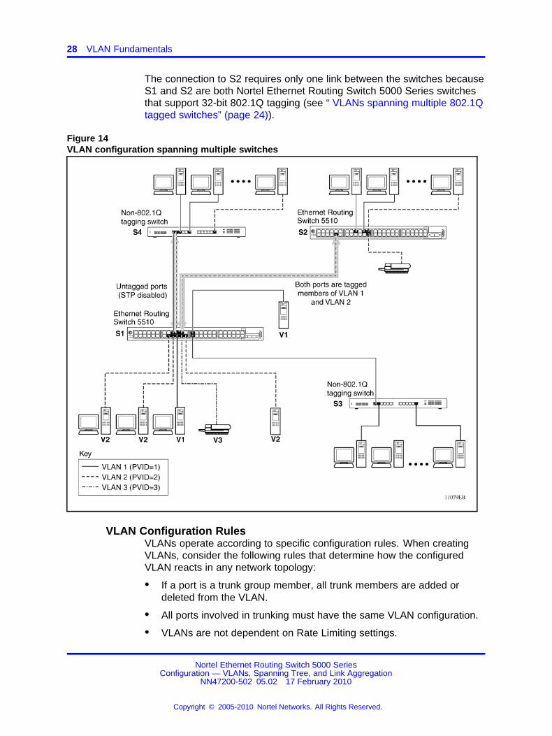
As shown in Figure 14 "VLAN configuration spanning multiple switches"(page 28), Switch S1 (Nortel Ethernet Routing Switch 5510) is configuredwith multiple VLANs:
• Ports 17, 20, 25, and 26 are in VLAN 1.
• Ports 16, 18, 19, 21, and 24 are in VLAN 2.
• Port 22 is in VLAN 3.
Because S4 does not support 32-bit 802.1Q tagging, a single switch porton each switch must be used for each VLAN (see Figure 12 "VLANsspanning multiple untagged switches" (page 26)).
Nortel Ethernet Routing Switch 5000 SeriesConfiguration — VLANs, Spanning Tree, and Link Aggregation
NN47200-502 05.02 17 February 2010
Copyright © 2005-2010 Nortel Networks. All Rights Reserved.
.
28 VLAN Fundamentals
The connection to S2 requires only one link between the switches becauseS1 and S2 are both Nortel Ethernet Routing Switch 5000 Series switchesthat support 32-bit 802.1Q tagging (see “ VLANs spanning multiple 802.1Qtagged switches” (page 24)).
Figure 14VLAN configuration spanning multiple switches
VLAN Configuration RulesVLANs operate according to specific configuration rules. When creatingVLANs, consider the following rules that determine how the configuredVLAN reacts in any network topology:
• If a port is a trunk group member, all trunk members are added ordeleted from the VLAN.
• All ports involved in trunking must have the same VLAN configuration.
• VLANs are not dependent on Rate Limiting settings.
Nortel Ethernet Routing Switch 5000 SeriesConfiguration — VLANs, Spanning Tree, and Link Aggregation
NN47200-502 05.02 17 February 2010
Copyright © 2005-2010 Nortel Networks. All Rights Reserved.
.

VLAN Configuration Control 29
• If a port is an Internet Gateway Management Protocol (IGMP)member on any VLAN, and is removed from a VLAN, the port’s IGMPmembership is also removed.
• If you add a port to a different VLAN, and it is already configured as astatic router port, you configure the port as an IGMP member on thatspecific VLAN.
VLAN Configuration ControlVLAN Configuration Control (VCC) allows a switch administrator to controlhow VLANs are modified. VLAN Configuration Control is a superset ofthe existing AutoPVID functionality and incorporates this functionality forbackwards compatibility. VLAN Configuration Control is globally appliedto all VLANs on the switch.
VLAN Configuration Control offers four options for controlling VLANmodification:
1. Strict -- This option restricts the addition of an untagged port to aVLAN if it is already a member of another VLAN. To add an untaggedport to a new VLAN, the switch administrator must remove the portfrom all other VLANs of which it is a member before adding it to thenew VLAN. The PVID of the port is changed to the new VID to which itwas added.
Note: Strict is the factory default setting.
2. Automatic -- This option automatically adds an untagged port to anew VLAN and automatically removes it from any previous VLANmembership. The PVID of the port is automatically changed to theVID of the VLAN it joins. Since the port is first added to the new VLANand then removed from any previous membership, the Spanning TreeGroup participation of the port will not be disabled as long as theVLANs involved are in the same Spanning Tree Group.
3. AutoPVID -- This option functions in the same manner as previousAutoPVID functionality. When an untagged port is added to anew VLAN, the port is added to the new VLAN and the PVIDassigned to the new VID without removing it from any previousVLAN memberships. Using this option an untagged port can havemembership in multiple VLANs.
4. Flexible -- This option functions in a similar manner to disablingAutoPVID functionality. When this option is used, an untagged portcan belong to an unlimited number of VLANs. Any new additions of anuntagged port to a new VLAN does not change the PVID of that port.
Nortel Ethernet Routing Switch 5000 SeriesConfiguration — VLANs, Spanning Tree, and Link Aggregation
NN47200-502 05.02 17 February 2010
Copyright © 2005-2010 Nortel Networks. All Rights Reserved.
.

30 VLAN Fundamentals
VLAN Configuration Control is only applied to ports with the tagging modesof Untag All and Tag PVID Only. Ports with the tagging modes of Tag Alland Untag PVID Only are not governed by VLAN Configuration Control.Ports with the tagging modes of Tag All and Untag PVID Only can belongto multiple VLANs regardless of VLAN Configuration Control settings andmust have their PVID manually changed.
MultinettingThe Nortel Ethernet Routing Switch 5000 Series supports the definitionand configuration of secondary interfaces on each VLAN. For moreinformation about IP Multinetting, refer to Nortel Ethernet RoutingSwitch 5000 Series Configuration - IP Routing Protocols (), part numberNN47200-503.
Nortel Ethernet Routing Switch 5000 SeriesConfiguration — VLANs, Spanning Tree, and Link Aggregation
NN47200-502 05.02 17 February 2010
Copyright © 2005-2010 Nortel Networks. All Rights Reserved.
.

31.
Spanning Tree Protocol Fundamentals
Spanning Tree Protocol groupsThe Nortel Ethernet Routing Switch 5000 Series supports the SpanningTree Protocol (STP) as defined in IEEE 802.1D. The Spanning TreeProtocol detects and eliminates logical loops in a bridged or switchednetwork. When multiple paths exist, the spanning tree algorithm configuresthe network so that a bridge or switch uses only the most efficient path. Ifthat path fails, the protocol automatically reconfigures the network to makeanother path become active, thus sustaining network operations.
The Nortel Ethernet Routing Switch 5000 Series supports multiplespanning tree groups (STG). The Nortel Ethernet Routing Switch 5000Series supports a maximum of 8 STGs, either all in one stand-alone switchor across a stack. Multiple STGs provide multiple data paths, which canbe used for load-balancing and redundancy. Load balancing is enabledbetween two switches using multiple STGs by configuring each path with adifferent VLAN and then assigning each VLAN to a separate STG. EachSTG is independent. Each STG sends its own Bridge Protocol Data Units(BPDU), and each STG must be independently configured.
The STG, or bridge group, forms a loop-free topology that includes oneor more virtual LANs (VLAN). The Nortel Ethernet Routing Switch 5000Series supports multiple instances (8) of STGs running simultaneously.
The Nortel Ethernet Routing Switch 5000 Series supports a maximum of256 VLANs. With a maximum of 8 STGs, on average, each STG can have32 VLANs.
In the default configuration of the Nortel Ethernet Routing Switch 5000Series, a single STG with the ID of 1 includes all ports on the switch. ThisSTG is the default STG. Although ports can be added to or deleted fromthe default STG, the default STG (STG1) itself cannot be deleted from thesystem. Also you cannot delete the default VLAN (VLAN1) from STG1.
The tagging for the BPDUs from STG1, or the default STG, isuser-configurable (as are tagging settings for all STGs). However,by default STG1 sends out only untagged BPDUs to operate with all
Nortel Ethernet Routing Switch 5000 SeriesConfiguration — VLANs, Spanning Tree, and Link Aggregation
NN47200-502 05.02 17 February 2010
Copyright © 2005-2010 Nortel Networks. All Rights Reserved.
.

32 Spanning Tree Protocol Fundamentals
devices that support only one instance of STP. (The default tagging ofSTG2 through STG8 is tagged.) The tagging setting for each STG isuser-configurable.
Note: If the STG is tagging a BPDU, the BPDU packet is tagged onlyon a tagged port. Also, ensure that the Filter Unregistered Framesoption for the tagged port is disabled for this to function properly.
All other STGs, except the Default STG, must be created by the user. Tobecome active, each STG must be enabled by the user after creation.Each STG is assigned an ID number from 2 to 8 (the Default STG isassigned the ID number 1). Ports or VLANs are assigned to an activeSTG. However, a port that is not a member of a VLAN is not allowed tojoin an STG.
When an STG is created, all ports belonging to any assigned VLAN areautomatically added to the STG.
When an STG is no longer needed, disable and delete it. The procedureis to disable the STG, delete all VLAN and port memberships, and thendelete the STG.
A unique multicast address can be configured for STGs 1 to 4.
Note 1: If a unique multicast address for an STG is configured, eachdevice in that STG must also be configured with the same spanningtree multicast address.
Note 2: If Virtual LACP is enabled, the number of unique multicastaddresses that can be configured for STGs is reduced to 3 (1 to 3).
STG Configuration GuidelinesThis section provides important information about configuring STGs:
• An STG must be created by following these steps:
— Create the STG
— Add the existing VLAN and port memberships
— Enable the STG
• When a VLAN is created, that VLAN automatically belongs to STG 1,the default STG. If the VLAN is to be in another STG, it must be movedby assigning it to another STG.
• A newly created VLAN must be moved to an existing STG by followingthese steps:
— Create the VLAN
— Add the VLAN to an existing STG
Nortel Ethernet Routing Switch 5000 SeriesConfiguration — VLANs, Spanning Tree, and Link Aggregation
NN47200-502 05.02 17 February 2010
Copyright © 2005-2010 Nortel Networks. All Rights Reserved.
.

Spanning Tree Protocol groups 33
• VLAN1 cannot be moved or deleted from STG1.
• You can create and add VLAN X directly to STG Y with vlan createX type port Y from the NNCLI if STG Y exists.
• VLANs must be contained within a single STG; a VLAN cannot spanmultiple STGs. By confining VLANs within a single STG, you avoidproblems with spanning tree blocking ports and causing a loss ofconnectivity within the VLAN. When a VLAN spans multiple switches,the VLAN must be within the same spanning tree group (have thesame STG ID) across all the switches.
• A port that is not a member of any VLAN cannot be added to anySTG. The port must be added to a VLAN, and that VLAN added to thedesired STG.
• Tagged ports can belong to more than one STG, but untagged portscan belong to only one STG.
• When a tagged port belongs to more than one STG, the egress BPDUsare tagged to distinguish the BPDUs of one STG from those of anotherSTG.
• Because some STP-compliant devices do not support tagging, youcan configure whether to send tagged or untagged BPDUs, even fromtagged ports. The VLAN ID for the tagged BPDUs is 4000+STG ID.
• The default VLAN ID for tagged BPDUs is as follows:
— 4001--STG1
— 4002--STG2
— 4003--STG3
— 4004--STG4
— 4005--STG5
— 4006--STG6
— 4007--STG7
— 4008--STG8
• A VLAN ID can be selected for tagged BPDUs for each STG. ValidVLAN IDs are 1 to 4094.
• Tagged BPDUs cannot use the same VID as an active VLAN.
• An untagged port cannot span multiple STGs.
• When a port is removed from a VLAN that belongs to an STG, that portis also removed from the STG. However, if that port belongs to anotherVLAN in the same STG, the port remains in the STG.
Nortel Ethernet Routing Switch 5000 SeriesConfiguration — VLANs, Spanning Tree, and Link Aggregation
NN47200-502 05.02 17 February 2010
Copyright © 2005-2010 Nortel Networks. All Rights Reserved.
.

34 Spanning Tree Protocol Fundamentals
• As an example, assume that port 1 belongs to VLAN1, and thatVLAN1 belongs to STG1. When you remove port 1 from VLAN1, port 1is also removed from STG1.
However, if port 1 belongs to both VLAN1 and VLAN2 and both VLANsbelong to STG1, removing port 1 from VLAN1 does not remove port 1from STG1 because VLAN2 is still a member of STG1.
An STG cannot be deleted until you disable it.
• A unique multicast address can be configured for STGs 1 to 4 only.
Spanning Tree Fast LearningSpanning Tree Fast Learning is an enhanced port mode supported bythe Nortel Ethernet Routing Switch 5000 Series. If Spanning Tree FastLearning is enabled on a port with no other bridges, the port is broughtup more quickly after a switch initialization or a spanning tree change.The port goes through the normal blocking and learning states before theforwarding state, but the hold times for these states is the bridge hellotimer (2 seconds by default) instead of the bridge forward delay timer (15seconds by default).
The port set with Fast Learning can forward data immediately, as soon asthe switch learns that the port is enabled.
Fast Learning is intended for access ports in which only one device isconnected to the switch (as in workstations with no other spanning treedevices). For these ports, it is not desirable to wait the usual 30 to 35seconds for spanning tree initialization and bridge learning.
Note: Use Spanning Tree Fast Learning with caution. This procedureis contrary to that specified in the IEEE 802.1D standard for SpanningTree Protocol (STP) in which a port enters the blocking state after theinitialization of the bridging device, or after a return from the disabledstate when the port is enabled through configuration.
STG port membership modeIEEE 802.1D STGs support two different STP port membership modes:normal and auto. In the normal mode, when a port is assigned to VLAN Xand VLAN X is in STP group Y, the port does not automatically becomea member of STP group Y. In the auto mode, when a port is assigned toVLAN X and VLAN X is in STP group Y, the port automatically becomesa member of STP group Y.
To set the STG port membership mode using the NNCLI, see “ConfiguringSTG port membership mode” (page 161) and using DM, see “ConfiguringSTG global properties” (page 233).
Nortel Ethernet Routing Switch 5000 SeriesConfiguration — VLANs, Spanning Tree, and Link Aggregation
NN47200-502 05.02 17 February 2010
Copyright © 2005-2010 Nortel Networks. All Rights Reserved.
.

Multiple Spanning Tree Protocol 35
802.1t path cost calculationYou can set the switch to calculate the STG path cost using either theIEEE 802.1d standard or the IEEE 802.1t standard. The 802.1t standard isa maintenance extension to the 802.1d standard.
To set the path cost calculation mode for the switch, see “Configuring pathcost calculation mode” (page 161).
Rapid Spanning Tree ProtocolThe standard Spanning Tree implementation in 5000 Series switches isbased on IEEE 802.1d, which is slow to respond to a topology change inthe network (for example, a dysfunctional link in a network).
The Rapid Spanning Tree Protocol (RSTP or IEEE 802.1w) reducesrecovery time after a network breakdown. It also maintains a backwardcompatibility with the IEEE 802.1d, which was the Spanning Treeimplementation prior to RSTP. In certain configurations, the recoverytime of RSTP can be reduced to less than 1 second. The backwardcompatibility is maintained by configuring a port to be in STP-compatiblemode. A port operating in the STP-compatible mode transmits andreceives only STP BPDUs and drops any RSTP BPDUs.
RSTP also reduces the amount of flooding in the network by enhancingthe way the Topology Change Notification (TCN) packet is generated.
Multiple Spanning Tree ProtocolYou can use the Multiple Spanning Tree Protocol (MSTP or IEEE 802.1s)to configure multiple instances of RSTP on the same switch. Each RSTPinstance can include one or more VLANs. The operation of the MSTP issimilar to the current Nortel proprietary MSTP.
RSTP and MSTP enable the 5000 Series switch to achieve the following:
• Reduction of converging time from 30 seconds to less than 1 or 2seconds when a topology change occurs in the network (that is, theport going up or down).
• Elimination of unnecessary flushing of the MAC database and floodingof traffic to the network with a new Topology Change mechanism.
• Backward compatibility with other switches that are running legacy802.1d STP or Nortel MSTP (STP group 1 only).
• Under MSTP mode, simultaneous support of eight instances of RSTP.Instance 0 or CIST is the default group, which includes default VLAN 1.Instances 1 to 7 are called MSTIs 1-7.
• Ability to run Nortel MSTP, RSTP, or MSTP.
Nortel Ethernet Routing Switch 5000 SeriesConfiguration — VLANs, Spanning Tree, and Link Aggregation
NN47200-502 05.02 17 February 2010
Copyright © 2005-2010 Nortel Networks. All Rights Reserved.
.

36 Spanning Tree Protocol Fundamentals
Interoperability with legacy STPRSTP provides a new parameter ForceVersion for backward compatibilitywith legacy STP. You can configure a port in either STP-compatible orRSTP mode.
• An STP compatible port transmits and receives only STP BPDUs. AnyRSTP BPDU that the port receives in this mode is discarded.
• An RSTP compatible port transmits and receives only RSTP BPDUs. Ifan RSTP port receives an STP BPDU, it becomes an STP port. Userintervention is required to bring this port back to RSTP mode. Thisprocess is called Port Protocol Migration.
Differences in STP and RSTP port rolesRSTP is an enhanced version of STP. These two protocols have almostthe same set of parameters.
Table 1 "Differences in port roles for STP and RSTP" (page 36) lists thedifferences in port roles for STP and RSTP. STP supports 2 port roles,while RSTP supports four port roles.
Table 1Differences in port roles for STP and RSTP
Port Role STP RSTP Description
Root Yes Yes This port is receiving a better BPDU thanits own and has the best path to reachthe Root. Root port is in Forwardingstate.
Designated Yes Yes This port has the best BPDU on thesegment. The Designated port is inForwarding state.
Alternate No Yes This port is receiving a better BPDU thanits own and a Root port exists within thesame switch. The Alternate port is inDiscarding state.
Backup No Yes This port is receiving a better BPDU thanits own from another port within the sameswitch. The Backup port is in Discardingstate.
Edge portEdge port is a new parameter supported by RSTP. When a port isconnected to a non-switch device such as a PC or a workstation, it mustbe configured as an Edge port for fast convergence. An active Edgeport goes directly to Forwarding state without any delay. An Edge portbecomes a non-Edge port if it receives a BPDU.
Nortel Ethernet Routing Switch 5000 SeriesConfiguration — VLANs, Spanning Tree, and Link Aggregation
NN47200-502 05.02 17 February 2010
Copyright © 2005-2010 Nortel Networks. All Rights Reserved.
.

Multiple Spanning Tree Protocol 37
Path cost valuesRSTP and MSTP recommend new path cost values that support a widerange of link speeds. Table 2 "Recommended path cost values" (page37) lists the recommended path cost values.
Table 2Recommended path cost values
Link speed Recommended value
Less than or equal to 100 Kbit/s
1 Mbit/s
10 Mbit/s
100 Mbit/s
200 000 000
20 000 000
2 000 000
200 000
1 Gbit/s
10 Gbit/s
100 Gbit/s
20 000
2 000
200
1 Tbit/s
10 Tbit/s
20
2
Rapid convergentIn RSTP and MSTP, the environment root port or the designated portcan ask its peer for permission to go to the Forwarding State. If the peeragrees, then the root port moves to the Forwarding State without anydelay. This procedure is called the Negotiation Process.
RSTP and MSTP also allow information received on a port to be sentimmediately if the port becomes dysfunctional, instead of waiting for theMaximum Age time.
The following example illustrates how an RSTP port state moves rapidly toForwarding state without the risk of creating a loop in the network.
Switch A: ports 1 and 2 are in full duplex. Port 2 is an Edge port.
Switch B: ports 1, 2, and 3 are in full duplex. Port 2 is an Edge port.
Switch C: ports 1 and 2 are in full duplex. Port 2 is an Edge port.
Nortel Ethernet Routing Switch 5000 SeriesConfiguration — VLANs, Spanning Tree, and Link Aggregation
NN47200-502 05.02 17 February 2010
Copyright © 2005-2010 Nortel Networks. All Rights Reserved.
.

38 Spanning Tree Protocol Fundamentals
Switch A is the Root.
Negotiation ProcessAfter powering up, all ports assume the role as Designated ports. All portsare in the Discarding state, except for Edge ports. Edge ports go directly tothe Forwarding state without delay.
Switch A port 1 and switch B port 1 exchange BPDUs, and switch A knowsthat it is the Root and that switch A port 1 is the Designated port. Switch Blearns that switch A has better priority. Switch B port 1 becomes the Rootport. Both switch A port 1 and switch B port 1 are still in the Discardingstate.
Switch A starts the negotiation process by sending a BPDU with aproposal bit set.
Switch B receives the proposal BPDU and sets its non-Edge ports to theDiscarding state. This operation is the sync process.
Switch B sends a BPDU with the agreement bit set to switch A.
Switch A sets port 1 to Forwarding, and switch B sets port 1 to Forwarding.PC 1 and PC 2 can talk to each other.
• The negotiation process now moves down to switch B port 3 and itspartner port.
• PC 3 cannot talk to either PC 1 or PC 2 until the negotiation processbetween switch B and switch C is complete.
Nortel Ethernet Routing Switch 5000 SeriesConfiguration — VLANs, Spanning Tree, and Link Aggregation
NN47200-502 05.02 17 February 2010
Copyright © 2005-2010 Nortel Networks. All Rights Reserved.
.

Spanning Tree BPDU Filtering 39
Figure 15Negotiation process
The RSTP convergent time depends on how quickly the switch canexchange BPDUs during the negotiation process, and the number ofswitches in the network. For a 5000 Series switch, the convergent timedepends on the hardware platform and the number of active applicationsrunning on the switch.
Spanning Tree BPDU FilteringThe Ethernet Routing Switch 5000 Series supports the BPDU-Filteringfeature for STPG, RSTP, and MSTP.
The Spanning Tree Protocol detects and eliminates logical loops in abridged or switched network. Any bridge that participates in the spanningtree exchanges information with other bridges using configurationmessages known as Bridge Protocol Data Units (BPDU). Based on theBPDU information exchange, the bridge with the lowest bridge ID becomesthe root. This process is called the root selection process.
Nortel Ethernet Routing Switch 5000 SeriesConfiguration — VLANs, Spanning Tree, and Link Aggregation
NN47200-502 05.02 17 February 2010
Copyright © 2005-2010 Nortel Networks. All Rights Reserved.
.

40 Spanning Tree Protocol Fundamentals
Typically, when a new bridge joins the spanning tree or an existing bridgeleaves the spanning tree, the root selection process is repeated and a newroot is selected.
The BPDU-Filtering feature allows the network administrator to achievethe following:
• Block an unwanted root selection process when an edge device, suchas a laptop running Linux and enabled with STP, is added to thenetwork. This prevents unknown devices from influencing an existingspanning tree topology.
• Block the flooding of BPDUs from an unknown device.
Note: The STP BPDU-Filtering feature is not supported on Multi-LinkTrunk (MLT) ports.
When a port has BPDU-Filtering enabled and it receives an STP BPDU,the following actions take place:
• The port is immediately put in the operational disabled state.
• A trap is generated and the following log message is written to the log:BPDU received on port with BPDU-Filtering enabled. Port<x> has been disabled
• The port timer starts.
• The port stays in the operational disabled state until the port timerexpires.
If the timer is disabled or the switch is reset before the timer expires,the port remains in the disabled state. Similarly, if a user disablesBPDU-Filtering while the timer is running, the timer is stopped and thatport stays in the disabled state. In this case, you must then manuallyenable the port to bring it back to the normal mode.
You can enable and disable the BPDU-Filtering feature on a per-portbasis. The BPDU-Filtering timer is user-configurable for each port andhas a valid range of between 10 and 65535 seconds. The port timer isdisabled if it is configured as 0.
For details on configuring BPDU Filtering, refer to: “Configuring STPBPDU Filtering using the NNCLI” (page 159) and “Configuring STP BPDUFiltering using Device Manager” (page 231).
Nortel Ethernet Routing Switch 5000 SeriesConfiguration — VLANs, Spanning Tree, and Link Aggregation
NN47200-502 05.02 17 February 2010
Copyright © 2005-2010 Nortel Networks. All Rights Reserved.
.

Configuring Spanning Tree using the Console Interface 41
Configuring Spanning Tree using the Console InterfaceThe following sections provide instructions for configuring Spanning Treein the three modes.
• “Spanning Tree configuration in STPG mode” (page 41)
• “Spanning Tree configuration in RSTP mode” (page 50)
• “Spanning Tree configuration in MSTP mode” (page 57)
Spanning Tree configuration in STPG modeFrom the Spanning Tree Configuration Menu screen in the STPG mode(IEEE 802.1d), you can view Spanning Tree parameters and configureindividual switch ports to participate in the Spanning Tree Algorithm.
To open the Spanning Tree Configuration Menu screen:
→ Choose Spanning Tree Configuration (or press p) from the main menu.
Table 3 "Spanning Tree Configuration Menu options in STPG mode."(page 41) describes the Spanning Tree Configuration Menu options.
Table 3Spanning Tree Configuration Menu options in STPG mode.
Option Description
Spanning Tree GroupConfiguration
Displays the Spanning Tree Group Configuration screen. (See“Spanning Tree Group Configuration screen in STPG mode” (page41).)
Spanning Tree PortConfiguration
Displays the Spanning Tree Port Configuration screen. (See“Spanning Tree Port Configuration screen in STPG mode” (page44).)
Display Spanning TreeSwitch Settings
Displays the Spanning Tree Switch Settings screen. (See “SpanningTree Switch Settings screen in STPG mode” (page 46).)
Display Spanning TreeVLAN Membership
Displays the Spanning Tree VLAN Membership screen.
Spanning Tree Group Configuration screen in STPG modeTo open the Spanning Tree Group Configuration screen
Step Action
1 Choose Spanning Tree Group Configuration (or press g) fromthe Spanning Tree Configuration Menu screen.
Nortel Ethernet Routing Switch 5000 SeriesConfiguration — VLANs, Spanning Tree, and Link Aggregation
NN47200-502 05.02 17 February 2010
Copyright © 2005-2010 Nortel Networks. All Rights Reserved.
.

42 Spanning Tree Protocol Fundamentals
Table 4Spanning Tree Group Configuration parameters in STPG mode
Parameter Description
STP Mode Shows the current STP operational mode for switch/stack. Themodes available are:• STPG (Nortel MSTP)
• RSTP (IEEE 802.1w)
• MSTP (IEEE 802.1s)
Creates a spanning tree group.
Default value 1
Create STP Group
Range 1 to 8
Deletes a spanning tree group.
Default value Blank
Delete STP Group
Range Configured STP groups from 1 to8
Configures the priority value of the bridge ID in hexadecimalnotation, which is the most significant byte of the bridge ID. STPuses this parameter to determine the root bridge (or designatedbridge). For example, the bridge with the lowest bridge ID becomesthe root bridge, with Bridge Priority values.
Default value 0x8000
Bridge Priority (inHex)
Range 0x0000 to 0xF000
Configures the Hello Interval (the amount of time betweentransmissions of BPDUs) for the STP Group. This parameter takeseffect only when this bridge becomes the root bridge.
Note: Although you can set the Hello Interval for a bridge usingbridge management software, after the spanning tree computationprocess is complete, all bridges participating in the spanning treenetwork use the root bridge Hello Interval parameter value. If anybridge becomes the root bridge, its Hello Interval parameter valuebecomes the Actual Hello Interval parameter value for all bridgesparticipating in the spanning tree network.
Default value 2 seconds
Bridge Hello Time
Range 1 to 10 seconds
Nortel Ethernet Routing Switch 5000 SeriesConfiguration — VLANs, Spanning Tree, and Link Aggregation
NN47200-502 05.02 17 February 2010
Copyright © 2005-2010 Nortel Networks. All Rights Reserved.
.

Configuring Spanning Tree using the Console Interface 43
Table 4Spanning Tree Group Configuration parameters in STPG mode (cont’d.)
Parameter Description
Configures the maximum age (in seconds) that a Hello messagecan attain before being discarded. This parameter takes effect onlywhen the bridge becomes the root bridge.
Note: If this bridge becomes the root bridge, its Maximum Age Timeparameter value becomes the Actual Maximum Age Time parametervalue for all bridges participating in the spanning tree network.
Default value 20 seconds
Bridge Max. Age Time
Range 6 to 40 seconds
Configures the Forward Delay parameter value for this bridge. Thisparameter takes effect only when this bridge becomes the rootbridge.
The Forward Delay parameter value specifies the amount of timethat the bridge ports remain in the Listening and Learning statesbefore entering the Forwarding state.
Note: All bridges participating in the spanning tree network use theroot bridge Forward Delay parameter value.
Default value 15 seconds
Bridge Forward DelayTime
Range 4 to 30 seconds
Adds a VLAN to the specified spanning tree group.
Default value 1
Add VLAN Membership
Range 1 to 4094.
Deletes a VLAN from the specified spanning tree group.
Default value Blank
Delete VLANMembership
Range Configured VLANs from 1 to4094
Specifies whether to send tagged or untagged BPDUs from atagged port.
Default value STP Group 1: No; Other STPGroups: Yes
Tagged BPDU on taggedport
Range No or Yes
Nortel Ethernet Routing Switch 5000 SeriesConfiguration — VLANs, Spanning Tree, and Link Aggregation
NN47200-502 05.02 17 February 2010
Copyright © 2005-2010 Nortel Networks. All Rights Reserved.
.

44 Spanning Tree Protocol Fundamentals
Table 4Spanning Tree Group Configuration parameters in STPG mode (cont’d.)
Parameter Description
Specifies the VLAN ID (VID) for tagged BPDU for the specifiedspanning tree group.
Default value 4001 to 4008 for STGs 1 through8, respectively
VID used for taggedBPDU
Range 1 to 4094
Specifies the STP Multicast Address.STP Multicast Address
Default value 01-80-C2-00-00-00
Sets the STP Group to active or inactive.Note: You cannot set the default STG (STG 1) to Inactive.
Default value Active for STG 1; Inactive forSTGs 2 to 8
STP Group State
Range Active or Inactive
--End--
Spanning Tree Port Configuration screen in STPG modeWith the Spanning Tree Port Configuration screen, you can configureindividual switch ports or all switch ports to participate in the SpanningTree.
Note: If spanning tree participation of any trunk member is changed(enabled or disabled), the spanning tree participation of all membersof that trunk is changed similarly.
Table 5 "Spanning Tree Port Configuration parameters in STPG mode"(page 44) describes the Spanning Tree Port Configuration screen fields.
Table 5Spanning Tree Port Configuration parameters in STPG mode
Field Description
Specifies the number of the spanning tree group (STG) to view.To view another STG, type that STG ID number and press Enter,or press the spacebar on your keyboard to toggle the STP Groupnumbers.
Default value 1
STP Group
Range Configured STP Groups from 1to 8
STP Mode Indicates the STP mode in which the switch or stack is operating.
Nortel Ethernet Routing Switch 5000 SeriesConfiguration — VLANs, Spanning Tree, and Link Aggregation
NN47200-502 05.02 17 February 2010
Copyright © 2005-2010 Nortel Networks. All Rights Reserved.
.

Configuring Spanning Tree using the Console Interface 45
Table 5Spanning Tree Port Configuration parameters in STPG mode (cont’d.)
Field Description
Unit This field only appears if the switch is participating in a stackconfiguration. The field specifies the number of the unit to view. Toview another unit, type its unit number and press Enter, or press thespacebar on your keyboard to toggle the unit numbers.
Port Indicates the switch port numbers that correspond to the field valuesin that row (for example, the field values in row 2 apply to switchport 2).
Note: The values in the Switch row affect all switch ports and, whenthe switch is part of a stack, the values in the Stack row affect allports in the entire stack.
Trunk The read-only data displayed in this column indicates the trunks thatcorrespond to the switch ports specified in the Trunk Members fieldsof the Trunk Configuration screen.
Configures any (or all) of ports on the switch for Spanning treeparticipation.
When an individual port is a trunk member, changing this settingfor one trunk member changes the setting for all members of thattrunk. Consider how this can change your network topology beforeyou change this setting.
The Fast Learning parameter is the same as Normal Learning,except that the state transition timer is shortened to 2 seconds.
Default value Normal Learning
Participation
Range Normal Learning, Fast Learning,Disabled
This read-only field is a bridge spanning tree parameter thatprioritizes the lowest port path cost to the root. When one or moreports have the same path cost, STP selects the path with thehighest priority (lowest numerical value).
Default value 128
Priority
Range 0 to 255
Nortel Ethernet Routing Switch 5000 SeriesConfiguration — VLANs, Spanning Tree, and Link Aggregation
NN47200-502 05.02 17 February 2010
Copyright © 2005-2010 Nortel Networks. All Rights Reserved.
.

46 Spanning Tree Protocol Fundamentals
Table 5Spanning Tree Port Configuration parameters in STPG mode (cont’d.)
Field Description
This read-only field is a bridge spanning tree parameter thatdetermines the lowest path cost to the root.
Default value in 802.1d mode:
• Path cost = 1000 / LANspeed in Mbyte/s
• 1 for 1 Gigabit port
in 802.1t mode:
• Path cost = 2*10^10 / LANspeed in Kbyte/s
• 20 000 for 1 Gigabit port(default on ERS5000)
.
The higher the LAN speed, thelower the path cost.
Path Cost
Range in 802.1d mode: 1 to 65535in 802.1t mode: 1 to 200 000000
This read-only field indicates the current port state within thespanning tree network. Each port can transition to various states,as determined by the Participation field setting. For example, whenthe Participation field is set to Disabled, the port does not participatein the spanning tree and transitions to the Forwarding state (thedefault). When the Participation field is set to Enabled, the porttransitions from the Disabled state through the Blocking, Listening,and Learning states before entering the Forwarding state.
Default value Topology dependent
State
Range Disabled, Blocking, Listening,Learning, Forwarding
Spanning Tree Switch Settings screen in STPG modeWith the Spanning Tree Switch Settings screen, you can view spanningtree parameter values for the Ethernet Routing Switch 5000 Series.
To open the Spanning Tree Switch Settings screen:
Nortel Ethernet Routing Switch 5000 SeriesConfiguration — VLANs, Spanning Tree, and Link Aggregation
NN47200-502 05.02 17 February 2010
Copyright © 2005-2010 Nortel Networks. All Rights Reserved.
.

Configuring Spanning Tree using the Console Interface 47
Step Action
1 Choose Display Spanning Tree Switch Settings (or press d)from the Spanning Tree Configuration Menu screen.
Table 6Spanning Tree Switch Settings parameters in STPG mode
Parameter Description
Specifies the number of the spanning tree group (STG) to view.To view another STG, type that STG ID number and press Enter,or press the spacebar on your keyboard to toggle the STP Groupnumbers.
Default value 1
STP Group
Range Configured STP Groups from 1to 8
STP Mode Shows the current STP operational mode for switch/stack:
• Nortel MSTP (STPG)
• IEEE 802.1w (RSTP)
• IEEE 802.1s (MSTP)
Indicates the management-assigned priority value of the bridge IDin hexadecimal notation, which is the most significant byte of thebridge ID. STP uses this parameter to determine the root bridge (ordesignated bridge). For example, the bridge with the lowest bridgeID becomes the root bridge, with Bridge Priority values comparedfirst, followed by the hardware addresses.
Default value 0x8000
Bridge Priority
Range HEX: 0x0000 - 0xF000
Designated Root Indicates the bridge ID of the root bridge, as determined byspanning tree.
Root Port Indicates the switch port number that offers the lowest path cost tothe root bridge.
Indicates the path cost from this switch port to the root bridge.
Default value 0
Root Path Cost
Range Unit 1-8Port 1-50 (in stack mode)
Port 1-50 (in standalone mode)
Defines the amount of time between transmissions of BPDUs.Hello Time
Range 1 to 10 seconds
Nortel Ethernet Routing Switch 5000 SeriesConfiguration — VLANs, Spanning Tree, and Link Aggregation
NN47200-502 05.02 17 February 2010
Copyright © 2005-2010 Nortel Networks. All Rights Reserved.
.

48 Spanning Tree Protocol Fundamentals
Table 6Spanning Tree Switch Settings parameters in STPG mode (cont’d.)
Parameter Description
Indicates the Maximum Age Time parameter value that the rootbridge is currently using. This value specifies the maximum age thata Hello message can attain before being discarded.
Note: The root bridge Maximum Age Time parameter value becomesthe actual Maximum Age Time parameter value for all bridgesparticipating in the spanning tree network.
Default value 20 seconds
Maximum Age Time
Range 6 to 40 seconds
Indicates the Forward Delay parameter value that the root bridgeis currently using. This value specifies the amount of time that thebridge ports remain in each of the Listening and Learning statesbefore entering the Forwarding state.
Note: The root bridge Forward Delay parameter value becomes theactual Forward Delay parameter value for all bridges participating inthe spanning tree network.
Default value 15 seconds
Forward Delay
Range 4 to 30 seconds
Defines the time interval (in seconds) for sending the BPDUs fromthe bridge.
Bridge Hello Time
Range 1 to 10 seconds
Specifies the maximum age (in seconds) that a Hello messagecan attain before being discarded. This parameter, specified bymanagement for this bridge, takes effect only when the bridgebecomes the root bridge.
Note: If this bridge becomes the root bridge, its Maximum Age Timeparameter value becomes the Actual Maximum Age Time parametervalue for all bridges participating in the spanning tree network.
Default value 20 seconds
Bridge Maximum AgeTime
Range 6 to 40 seconds
Nortel Ethernet Routing Switch 5000 SeriesConfiguration — VLANs, Spanning Tree, and Link Aggregation
NN47200-502 05.02 17 February 2010
Copyright © 2005-2010 Nortel Networks. All Rights Reserved.
.

Configuring Spanning Tree using the Console Interface 49
Table 6Spanning Tree Switch Settings parameters in STPG mode (cont’d.)
Parameter Description
Indicates the Forward Delay parameter value specified bymanagement for this bridge. This parameter takes effect only whenthis bridge becomes the root bridge.
The Forward Delay parameter value specifies the amount of timethat the bridge ports remain in each of the Listening and Learningstates before entering the Forwarding state.
Note: All bridges participating in the spanning tree network use theroot bridge Forward Delay parameter value.
Default value 15 seconds
Bridge Forward Delay
Range 4 to 30 seconds
--End--
Spanning Tree VLAN Membership screen in STPG modeWith the Spanning Tree VLAN Membership screen, you can view whichVLANs belong to the selected STP Group. (STP Group 1 is the defaultSTP group.)
To open the Spanning Tree VLAN Membership screen:
Step Action
1 Choose Spanning Tree VLAN Membership (or press v) fromthe Spanning Tree Configuration Menu screen.
Table 7Spanning Tree VLAN Membership parameters
Parameter Description
Specifies the number of the Spanning Tree Group instances to view. Toview another instance, press the spacebar on your keyboard to togglethe STP instances.
Default value 1
STP Group
Range 1 - 8. Only created STPs are displayed.
VLAN Membership Displays the total number of VLANs in the specified STP Group, as wellas the VLAN IDs of the VLAN members.
--End--
Nortel Ethernet Routing Switch 5000 SeriesConfiguration — VLANs, Spanning Tree, and Link Aggregation
NN47200-502 05.02 17 February 2010
Copyright © 2005-2010 Nortel Networks. All Rights Reserved.
.

50 Spanning Tree Protocol Fundamentals
Spanning Tree configuration in RSTP modeWith the Spanning Tree Configuration Menu screen, you can viewspanning tree parameters and configure individual switch ports toparticipate in the Spanning Tree Algorithm (STA).
To open the Spanning Tree Configuration Menu screen:
Step Action
1 Choose Spanning Tree Configuration (or press p) from themain menu.
Table 8Spanning Tree Configuration main menu options
Menu option Description
Spanning Tree Group Configuration Displays the Spanning Tree Group Configurationscreen. (See “Spanning Tree Group Configurationscreen in RSTP mode” (page 50).)
Spanning Tree Port Configuration Displays the Spanning Tree Port Configurationscreen. (See “Spanning Tree Port Configurationscreen in RSTP mode” (page 52).)
Display Spanning Tree Switch Settings Displays the Spanning Tree Switch Settings screen.(See “Spanning Tree Switch Settings screen in RSTPmode” (page 54).)
--End--
Spanning Tree Group Configuration screen in RSTP modeWith the Spanning Tree Group Configuration screen, you can create andconfigure spanning tree groups (STGs).
To open the Spanning Tree Group Configuration screen:
Step Action
1 Choose Spanning Tree Group Configuration (or press g) fromthe Spanning Tree Configuration Menu screen.
Nortel Ethernet Routing Switch 5000 SeriesConfiguration — VLANs, Spanning Tree, and Link Aggregation
NN47200-502 05.02 17 February 2010
Copyright © 2005-2010 Nortel Networks. All Rights Reserved.
.

Configuring Spanning Tree using the Console Interface 51
Table 9Spanning Tree Group Configuration parameters in RSTP mode
Parameter Description
STP Mode Shows the current STP operational mode for switch/stack:
• Nortel MSTP (STPG)
• IEEE 802.1w (RSTP)
• IEEE 802.1s (MSTP)
For the STP Group, configures the priority value of the bridge IDin hexadecimal notation, which is the most significant byte of thebridge ID. STP uses this parameter to determine the root bridge (ordesignated bridge). For example, the bridge with the lowest bridgeID becomes the root bridge, with Bridge Priority values.
Default value 0x8000
Bridge Priority (in Hex)
Range 0x0000 to 0xF000
For the STP Group, configures the Hello Interval (the amount of timebetween transmissions of BPDUs). This parameter takes effect onlywhen this bridge becomes the root bridge. Although you can setthe Hello Interval for a bridge using bridge management software,after the spanning tree computation process is complete, all bridgesparticipating in the spanning tree network use the root bridge HelloInterval parameter value. If any bridge becomes the root bridge, itsHello Interval parameter value becomes the Actual Hello Intervalparameter value for all bridges participating in the spanning treenetwork.
Default value 2 seconds
Bridge Hello Time
Range 1 to 10 seconds
For the STP Group, configures the maximum age (in seconds) thata Hello message can attain before being discarded. This parametertakes effect only when the bridge becomes the root bridge. If thisbridge becomes the root bridge, its Maximum Age Time parametervalue becomes the Actual Maximum Age Time parameter value forall bridges participating in the spanning tree network.
Default value 20 seconds
Bridge Max. Age Time
Range 6 to 40 seconds
Nortel Ethernet Routing Switch 5000 SeriesConfiguration — VLANs, Spanning Tree, and Link Aggregation
NN47200-502 05.02 17 February 2010
Copyright © 2005-2010 Nortel Networks. All Rights Reserved.
.

52 Spanning Tree Protocol Fundamentals
Table 9Spanning Tree Group Configuration parameters in RSTP mode (cont’d.)
Parameter Description
For the STP Group, configures the Forward Delay parameter valuefor this bridge. This parameter takes effect only when this bridgebecomes the root bridge. The Forward Delay parameter valuespecifies the amount of time that the bridge ports remain in theListening and Learning states before entering the Forwarding state.Note that all bridges participating in the spanning tree network usethe root bridge Forward Delay parameter value.
Default value 15 seconds
Bridge Forward DelayTime
Range 4 to 30 seconds
Bridge Tx Hold Count Indicates the number of BPDUs that are sent in each Hello Timeinterval. This number limits the maximum transmission rate.
Indicates the default representation of path costs.
32 bits (default in MSTP/RSTP mode, supported in STPG mode)
16 bits (default in STPG mode, supported in MSTP/RSTP mode).
Default Path Cost Type
Default value 32 bits in MSTP/RSTP mode16 bits in legacy STPG mode
--End--
Spanning Tree Port Configuration screen in RSTP modeWith the Spanning Tree Port Configuration screen, you can configureindividual switch ports or all switch ports for participation in the spanningtree.
Note: If spanning tree participation of any trunk member is changed(enabled or disabled), the spanning tree participation of all membersof that trunk is changed similarly.
Step Action
1 Choose Spanning Tree Port Configuration (or press c) fromthe Spanning Tree Configuration Menu to open the SpanningTree Port Configuration screen.
Nortel Ethernet Routing Switch 5000 SeriesConfiguration — VLANs, Spanning Tree, and Link Aggregation
NN47200-502 05.02 17 February 2010
Copyright © 2005-2010 Nortel Networks. All Rights Reserved.
.

Configuring Spanning Tree using the Console Interface 53
Table 10Spanning Tree Port Configuration parameters in RSTP mode
Field Description
Unit This field appears only if the switch is participating in a stackconfiguration. The field specifies the number of the unit to view. To viewanother unit, type its unit number and press Enter, or press the spacebaron your keyboard to toggle the unit numbers.
Port Indicates the switch port numbers that correspond to the field values inthat row (for example, the field values in row 2 apply to switch port 2).The values in the Switch row affect all switch ports, and when the switchis part of a stack, the values in the Stack row affect all ports in the entirestack.
Trunk The read-only data displayed in this column indicates the trunks thatcorrespond to the switch ports specified in the Trunk Members fields ofthe Trunk Configuration screen.
Indicates the port states of Spanning Tree.Learning
Range Enabled, Disabled
Edge Indicates if a port is an Edge port. When a port is connected to anon-switch device such as a PC or a workstation, configure it as an Edgeport. An active Edge port goes directly to Forwarding state without anydelay.
This read-only field is a bridge spanning tree parameter that prioritizes thelowest port path cost to the root. When one or more ports have the samepath cost, STP selects the path with the highest priority (lowest numericalvalue).
Default value 128
Priority
Range 0 to 255
This read-only field is a bridge spanning tree parameter that determinesthe lowest path cost to the root.
Default value 20000 for 1 Gigabit port
Path cost = 2*10^10/LAN speed (inKbits/s)
The higher the LAN speed, thelower the path cost.
Path Cost
Range 1 to 200 000 000
Nortel Ethernet Routing Switch 5000 SeriesConfiguration — VLANs, Spanning Tree, and Link Aggregation
NN47200-502 05.02 17 February 2010
Copyright © 2005-2010 Nortel Networks. All Rights Reserved.
.

54 Spanning Tree Protocol Fundamentals
Table 10Spanning Tree Port Configuration parameters in RSTP mode (cont’d.)
Field Description
Role A role represents a functionality characteristic or capability of a resourceto which policies are applied. The role of a port can be Root, Designated,Alternate, or Backup.
State Indicates the current state of the Port as defined by the Rapid SpanningTree Protocol. The state of a Port can be Forwarding in one instance andDiscarding (Blocking) in another.
--End--
Spanning Tree Switch Settings screen in RSTP modeWith the Spanning Tree Switch Settings screen, you can view spanningtree parameter values for the Ethernet Routing Switch 5000 Series.
To open the Spanning Tree Switch Settings screen:
Step Action
1 Choose Display Spanning Tree Switch Settings (or press d)from the Spanning Tree Configuration Menu screen.
Table 11Spanning Tree Switch Settings parameters in RSTP mode
Field Description
STP Mode Indicates the mode of the STP operation for the switch. The possiblevalues for the STP mode are:
• STPG (Nortel MSTP)
• RSTP (IEEE 802.1w)
• MSTP (IEEE 802.1s)
Indicates the management-assigned priority value of the bridge IDin hexadecimal notation, which is the most significant byte of thebridge ID. STP uses this parameter to determine the root bridge (ordesignated bridge). For example, the bridge with the lowest bridgeID becomes the root bridge, with Bridge Priority values comparedfirst, followed by the hardware addresses.
Default value 0x8000
Bridge Priority
Range HEX: 0x0000 - 0xF000
Nortel Ethernet Routing Switch 5000 SeriesConfiguration — VLANs, Spanning Tree, and Link Aggregation
NN47200-502 05.02 17 February 2010
Copyright © 2005-2010 Nortel Networks. All Rights Reserved.
.

Configuring Spanning Tree using the Console Interface 55
Table 11Spanning Tree Switch Settings parameters in RSTP mode (cont’d.)
Field Description
Designated Root This field specifies the unique Bridge Identifier of the bridge. It isrecorded as the CIST Root in the configuration BPDUs that aretransmitted.
Indicates the switch port number that offers the lowest path cost tothe root bridge. The local switch is the root bridge when this valueis 0 (path cost).
Default value 0
Root Port
Range Unit: 1-8, Port 1-50 (in stackmode)
Port: 1-98 (in standalone mode)
Indicates the path cost from this switch port to the root bridge.
Default value 0
Root Path Cost
Range Not applicable
Defines the amount of time between transmissions of BPDUs.Hello Time
Range 1 to 10 seconds
Indicates the Maximum Age Time parameter value that the rootbridge is currently using. This value specifies the maximum agethat a Hello message can attain before being discarded. The rootbridge Maximum Age Time parameter value becomes the actualMaximum Age Time parameter value for all bridges participating inthe spanning tree network.
Default value 20 seconds
Maximum Age Time
Range 6 to 40 seconds
Indicates the Forward Delay parameter value that the root bridgeis currently using. This value specifies the amount of time that thebridge ports remain in each of the Discarding and Learning statesbefore entering the Forwarding state.
The root bridge Forward Delay parameter value becomes the actualForward Delay parameter value for all bridges participating in thespanning tree network.
Default value 15 seconds
Forward Delay
Range 4 to 30 seconds
Nortel Ethernet Routing Switch 5000 SeriesConfiguration — VLANs, Spanning Tree, and Link Aggregation
NN47200-502 05.02 17 February 2010
Copyright © 2005-2010 Nortel Networks. All Rights Reserved.
.

56 Spanning Tree Protocol Fundamentals
Table 11Spanning Tree Switch Settings parameters in RSTP mode (cont’d.)
Field Description
For the STP Group, configures the Hello Interval. This parametertakes effect only when this bridge becomes the root bridge.
Although you can set the Hello Interval for a bridge using the bridgemanagement software, after the spanning tree computation processis complete, all bridges participating in the spanning tree networkuse the root bridge Hello Interval parameter value. If any bridgebecomes the root bridge, its Hello Interval parameter value becomesthe Actual Hello Interval parameter value for all bridges participatingin the spanning tree network.
Default value 2 seconds
Bridge Hello Time
Range 1 to 10 seconds
Specifies the maximum age (in seconds) that a Hello messagecan attain before being discarded. This parameter, specified bymanagement for this bridge, takes effect only when the bridgebecomes the root bridge.
If this bridge becomes the root bridge, its Maximum Age Timeparameter value becomes the Actual Maximum Age Time parametervalue for all bridges participating in the spanning tree network.
Default value 20 seconds
Bridge Maximum AgeTime
Range 6 to 40 seconds
Indicates the Forward Delay parameter value specified bymanagement for this bridge. This parameter takes effect only whenthis bridge becomes the root bridge.
The Forward Delay parameter value specifies the amount of timethat the bridge ports remain in each of the Discarding and Learningstates before entering the Forwarding state.
All bridges participating in the spanning tree network use the rootbridge Forward Delay parameter value.
Default value 15 seconds
Bridge Forward Delay
Range 4 to 30 seconds
Tx Hold Count This is the value used by the Port Transmit state machine to limit themaximum transmission rate. The value can range from 1 to 10
Default Path Cost Type Indicates the way that path cost is represented and used.
--End--
Nortel Ethernet Routing Switch 5000 SeriesConfiguration — VLANs, Spanning Tree, and Link Aggregation
NN47200-502 05.02 17 February 2010
Copyright © 2005-2010 Nortel Networks. All Rights Reserved.
.

Configuring Spanning Tree using the Console Interface 57
Spanning Tree configuration in MSTP modeWith the Spanning Tree Configuration Menu screen, you can viewspanning tree parameters and configure individual switch ports toparticipate in the spanning tree algorithm (STA).
To open the Spanning Tree Configuration Menu screen:
Step Action
1 Choose Spanning Tree Configuration (or press p) from themain menu.
Table 12Spanning Tree Configuration Menu options in MSTP mode
Option Description
Spanning Tree GroupConfiguration
Displays the Spanning Tree Group Configuration screen.
Spanning Tree Port Configuration Displays the Spanning Tree Port Configuration screen.
Display Spanning Tree SwitchSettings
Displays the Spanning Tree Switch Settings screen.
Display Spanning Tree VLANMembership
Displays the Spanning Tree VLAN Membership screen.
--End--
Spanning Tree Group Configuration screen in MSTP modeWith the Spanning Tree Group Configuration screen, you can create andconfigure spanning tree groups (STGs).
To open the Spanning Tree Group Configuration screen:
Step Action
1 Choose Spanning Tree Group Configuration (or press g) fromthe Spanning Tree Configuration Menu screen.
Nortel Ethernet Routing Switch 5000 SeriesConfiguration — VLANs, Spanning Tree, and Link Aggregation
NN47200-502 05.02 17 February 2010
Copyright © 2005-2010 Nortel Networks. All Rights Reserved.
.

58 Spanning Tree Protocol Fundamentals
Table 13Spanning Tree Group Configuration parameters in MSTP mode
Parameter Description
STP mode Indicates the STP mode in which the switch is operating. The availablemodes are:
• STPG (Nortel MSTP)
• RSTP (IEEE 802.1w)
• MSTP (IEEE 802.1s)
Creates a spanning Tree group. You can also use this parameter toselect the STP Group information to display.
Default value CIST
Create STP Group
Range 1 to 7 (MSTIs)
Deletes a spanning tree group. You cannot delete the CIST STP Group,and you can delete only nonactive STP Groups (that is, MSTIs).
Default Value Blank
Delete STP Group
Range 1 to 8; only created STP Groupsare available
For the STP Group, configures the priority value of the bridge ID inhexadecimal notation, which is the most significant byte of the bridge ID.STP uses this parameter to determine the root bridge (or designatedbridge). For example, the bridge with the lowest bridge ID becomes theroot bridge, with Bridge Priority values.
Default value 0x8000
Bridge Priority
Range 0x0000 -0xF000
For the STP Group, configures the maximum age (in seconds) that aHello message can attain before being discarded. This parameter takeseffect only when the bridge becomes the root bridge.
If this bridge becomes the root bridge, its Maximum Age Time parametervalue becomes the Actual Maximum Age Time parameter value for allbridges participating in the spanning tree network.
Default value 20 seconds
Bridge Max. AgeTime
Range 6 to 40 seconds
Nortel Ethernet Routing Switch 5000 SeriesConfiguration — VLANs, Spanning Tree, and Link Aggregation
NN47200-502 05.02 17 February 2010
Copyright © 2005-2010 Nortel Networks. All Rights Reserved.
.

Configuring Spanning Tree using the Console Interface 59
Table 13Spanning Tree Group Configuration parameters in MSTP mode (cont’d.)
Parameter Description
For the STP Group, configures the Forward Delay parameter value forthis bridge. This parameter takes effect only when this bridge becomesthe root bridge.
The Forward Delay parameter value specifies the amount of time that thebridge ports remain in each of the Discarding and Learning states beforeentering the Forwarding state.
All bridges participating in the spanning tree network use the root bridgeForward Delay parameter value.
Default value 15 seconds
Bridge Forward DelayTime
Range 4 to 30 seconds
Indicates the number of BPDUs that are sent in each Hello Time interval.The value used by the Port Transmit state machine to limit the maximumtransmission rate.
Default value 3
Bridge Tx Hold Count
Range 1 to 10
The Maximum Hop Count value in 1/100 seconds. The specified valuemust be a multiple of 100.
Default value 2000
Max. Hop Count
Range 600 to 4000, measured in 1/100second
The version of the Spanning Tree default Path Costs that are used bythis Bridge. A value of 16 Bits specifies the 16-bit default path costsfrom IEEE Standard 802.1D-1998. A value of 32 Bits specifies the 32-bitdefault path costs from IEEE Standard 802.1t.
Default value 32 Bits
Default Path CostType
Range 16 Bits, 32 Bits
Adds a VLAN to the specified spanning tree group.
Note: This field is updated with active VLANs currently defined in thesystem. A newly created and active VLAN is assigned to STP Group1 by default.
Default value 1
Add VLANMembership
Range 1 to 4094
Nortel Ethernet Routing Switch 5000 SeriesConfiguration — VLANs, Spanning Tree, and Link Aggregation
NN47200-502 05.02 17 February 2010
Copyright © 2005-2010 Nortel Networks. All Rights Reserved.
.

60 Spanning Tree Protocol Fundamentals
Table 13Spanning Tree Group Configuration parameters in MSTP mode (cont’d.)
Parameter Description
Deletes a VLAN from the specified STP group.
Note: You cannot remove VLAN 1 from STP Group 1.
Default value Blank
Delete VLANMembership
Range 1 to 4094; but only configured onesare available
Specifies whether the MSTI is active or inactive.
Note: You cannot set the default STG (CIST) to inactive. To enable anSTP Group, at least one active VLAN must be assigned to that STPGroup (MSTI).
Default value Active for CIST; Inactive for MSTIs1 to 7.
STP Group State
Range Active or Inactive
--End--
Spanning Tree Port Configuration screen in MSTP modeWith the Spanning Tree Port Configuration screen, you can configureindividual switch ports or all switch ports for participation in the spanningtree.
Note: If spanning tree participation of any trunk member is changed(enabled or disabled), the spanning tree participation of all membersof that trunk is changed similarly.
Step Action
1 Choose Spanning Tree Port Configuration (or press c) fromthe Spanning Tree Configuration Menu to open the SpanningTree Port Configuration screen.
Table 14Spanning Tree Port Configuration screen fields in MSTP mode
Field Description
STP Group Specifies the MSTP instance for which to display the port properties.Press the spacebar to toggle between the CIST and the configured MSTIinstances.
Nortel Ethernet Routing Switch 5000 SeriesConfiguration — VLANs, Spanning Tree, and Link Aggregation
NN47200-502 05.02 17 February 2010
Copyright © 2005-2010 Nortel Networks. All Rights Reserved.
.

Configuring Spanning Tree using the Console Interface 61
Table 14Spanning Tree Port Configuration screen fields in MSTP mode (cont’d.)
Field Description
Port Indicates the switch port numbers that correspond to the field values inthat row (for example, the field values in row 2 apply to switch port 2).The values in the Switch row affect all switch ports, and when the switchis part of a stack, the values in the Stack row affect all ports in the entirestack.
Trunk The read-only data displayed in this column indicates the trunks thatcorrespond to the switch ports specified in the Trunk Members fields ofthe Trunk Configuration screen.
Configures any (or all) of the switch ports for Spanning tree participation.
When an individual port is a trunk member (see Trunk field), changingthis setting for one of the trunk members changes the setting for allmembers of that trunk. Consider how this will change your networktopology before you change this setting.
Learning
Default value Enabled
A value of Yes indicates that this port is to be assumed as an edge-portand a value of No indicates that this port is to be assumed as anon-edge port.
Default value No
Edge
Range No, Yes
This read-only field is a bridge spanning tree parameter that prioritizesthe lowest port path cost to the root. When one or more ports have thesame path cost, STP selects the path with the highest priority (lowestnumerical value).
Default value 128
Priority
Range 0 to 255
This read-only field is a bridge spanning tree parameter that determinesthe lowest path cost to the root.
Default value Default value is 20000 for 1 Gigabit port
Path Cost = 2*10^10/LAN speed (in Kbit/s)
The higher the LAN speed, the lower the pathcost.
Path Cost
Range 1 to 200 000 000
The current role of the port as defined by Multiple Spanning TreeProtocol.
Default Disabled
Role
Range Disabled, Root, Designated, Alternate, Backup
Nortel Ethernet Routing Switch 5000 SeriesConfiguration — VLANs, Spanning Tree, and Link Aggregation
NN47200-502 05.02 17 February 2010
Copyright © 2005-2010 Nortel Networks. All Rights Reserved.
.

62 Spanning Tree Protocol Fundamentals
Table 14Spanning Tree Port Configuration screen fields in MSTP mode (cont’d.)
Field Description
This read-only field indicates the current port state within the spanningtree network. Each port can transition to various states, as determinedby the Participation field setting. For example, when the Participationfield is set to Disabled, the port does not participate in the spanningtree and transitions to the Forwarding state (the default). When theParticipation field is set to Enabled, the port transitions from the Disabledstate through the Blocking, Listening, and Learning states beforeentering the Forwarding state.
Default value Topology dependent
State
Range Discarding, Learning, Forwarding
--End--
Spanning Tree Switch Settings screen in MSTP modeWith the Spanning Tree Switch Settings screen, you can view spanningtree parameter values for the Ethernet Routing Switch 5000 Series.
To open the Spanning Tree Switch Settings screen:
Step Action
1 Choose Display Spanning Tree Switch Settings (or press d)from the Spanning Tree Configuration Menu screen.
Table 15Spanning Tree Switch Settings parameters in MSTP mode
Parameter Description
STP Group Specifies the MSTP instance for which to display the properties. Pressthe spacebar to toggle between the CIST and the configured MSTIinstances.
Indicates the management-assigned priority value of the bridge ID inhexadecimal notation, which is the most significant byte of the bridge ID.STP uses this parameter to determine the root bridge (or designatedbridge). For example, the bridge with the lowest bridge ID becomes theroot bridge, with Bridge Priority values compared first, followed by thehardware addresses.
Default value 8000
Bridge Priority
Range 0x0000 - 0xF000
Nortel Ethernet Routing Switch 5000 SeriesConfiguration — VLANs, Spanning Tree, and Link Aggregation
NN47200-502 05.02 17 February 2010
Copyright © 2005-2010 Nortel Networks. All Rights Reserved.
.

Configuring Spanning Tree using the Console Interface 63
Table 15Spanning Tree Switch Settings parameters in MSTP mode (cont’d.)
Parameter Description
CIST Root Common and Internal Spanning Tree (CIST) Root field shows the CISTExternal or Internal Root elected between devices.CIST Internal Root is used only on devices from the same region. CISTExternal (Common Spanning Tree) Root is elected between devicesfrom different regions or between devices with different STP modes.This parameter displays these values depending on networkconfiguration.
Regional Root Shows the CIST Regional Root bridge elected between devices from thesame region (in other words, the root for the Region).
Indicates the switch port number that offers the lowest path cost to theroot bridge. The local switch is the root bridge when this value is 0 (pathcost).
Root Port
Range Unit: 1-8, Port 1-50 (in stackmode)
Port: 1-50 (in standalone mode)
Indicates the path cost from this switch port to the root bridge.
Default value 0
Root Path Cost
Range Not applicable
Regional Root PathCost
Indicates the Path Cost to CIST Regional Root seen from this device.
Indicates the Maximum Age Time parameter value that the root bridgeis currently using. This value specifies the maximum age that a Hellomessage can attain before being discarded.
The root bridge Maximum Age Time parameter value becomes theactual Maximum Age Time parameter value for all bridges participatingin the spanning tree network.
Default value 20 seconds
Maximum Age Time
Range 6 to 40 seconds
Nortel Ethernet Routing Switch 5000 SeriesConfiguration — VLANs, Spanning Tree, and Link Aggregation
NN47200-502 05.02 17 February 2010
Copyright © 2005-2010 Nortel Networks. All Rights Reserved.
.

64 Spanning Tree Protocol Fundamentals
Table 15Spanning Tree Switch Settings parameters in MSTP mode (cont’d.)
Parameter Description
Indicates the Forward Delay parameter value that the root bridge iscurrently using. This value specifies the amount of time that the bridgeports remain in the Listening and Learning states before entering theForwarding state.
The root bridge Forward Delay parameter value becomes the actualForward Delay parameter value for all bridges participating in thespanning tree network.
Default value 15 seconds
Forward Delay
Range 4 to 30 seconds
This value determines the time interval during which no more than twoconfiguration BPDUs can be transmitted by this node.
Bridge Hold Time
Default value 1 second
Specifies the maximum age (in seconds) that a Hello messagecan attain before being discarded. This parameter, specified bymanagement for this bridge, takes effect only when the bridge becomesthe root bridge.
If this bridge becomes the root bridge, its Maximum Age Timeparameter value becomes the Actual Maximum Age Time parametervalue for all bridges participating in the spanning tree network.
Default value 20 seconds
Bridge Maximum AgeTime
Range 6 to 40 seconds
Indicates the Forward Delay parameter value specified by managementfor this bridge. This parameter takes effect only when this bridgebecomes the root bridge.
The Forward Delay parameter value specifies the amount of time thatthe bridge ports remain in the Listening and Learning states beforeentering the Forwarding state.
All bridges participating in the spanning tree network use the root bridgeForward Delay parameter value.
Default value 15 seconds
Bridge Forward Delay
Range 4 to 30 seconds
Nortel Ethernet Routing Switch 5000 SeriesConfiguration — VLANs, Spanning Tree, and Link Aggregation
NN47200-502 05.02 17 February 2010
Copyright © 2005-2010 Nortel Networks. All Rights Reserved.
.

Configuring Spanning Tree using the Console Interface 65
Table 15Spanning Tree Switch Settings parameters in MSTP mode (cont’d.)
Parameter Description
Indicates the number of BPDUs that are sent in each Hello Timeinterval. This number limits the maximum transmission rate.
Default value 3
Tx Hold Count
Range 1 to 10
This value is decremented by each device (inside a region) startingfrom Regional Root switch. When it reaches 0 (zero), STP informationis discarded, and a new root is elected. The Root port on this devicebecomes a Designated port.
Default value 2000 (20 hops)
Hop Count (Max)
Range 600 to 4000 (6 to 40 hops).
Indicates the default representation of path costs.
32 bits (default in MSTP/RSTP mode, supported in STPG mode)
16 bits (default in STPG mode, supported in MSTP/RSTP mode).
Default Path CostType
Default value 32 bits in MSTP/RSTP mode16 bits in legacy STPG mode
Name of the Region. CIST External Root interprets devices from thesame region as a single switch.
Default value The MAC address of the device
Region Name
Range 1 to 32 chars (string)
--End--
Spanning Tree VLAN Membership screen in MSTP modeWith the Spanning Tree VLAN Membership screen, you can view whichVLANs belong to the selected STP Group. (The CIST is displayed bydefault.)
To open the Spanning Tree VLAN Membership screen:
Step Action
1 Choose Spanning Tree VLAN Membership (or press v) fromthe Spanning Tree Configuration Menu screen.
Nortel Ethernet Routing Switch 5000 SeriesConfiguration — VLANs, Spanning Tree, and Link Aggregation
NN47200-502 05.02 17 February 2010
Copyright © 2005-2010 Nortel Networks. All Rights Reserved.
.

66 Spanning Tree Protocol Fundamentals
Table 16Spanning Tree VLAN Membership parameters
Parameter Description
Specifies the number of the Spanning Tree Group instances(CIST/MSTI) you want to view. To view another instance, press thespacebar on your keyboard to toggle the STP instances (MSTIs).
Default value CIST
STP Group
Range CIST, MSTI-1 to MSTI-7. Only created MSTIs aredisplayed.
VLAN Membership Displays the total number of VLANs in the specified STP Group, as wellas the VLAN IDs of the VLAN members.
--End--
Nortel Ethernet Routing Switch 5000 SeriesConfiguration — VLANs, Spanning Tree, and Link Aggregation
NN47200-502 05.02 17 February 2010
Copyright © 2005-2010 Nortel Networks. All Rights Reserved.
.

67.
Multi-Link Trunking FundamentalsThe following sections contain fundamental information regardingMulti-Link Trunking.
Multi-Link trunksWith Multi-Link trunks, you can group up to eight switch ports togetherto form a link to another switch or server, thus increasing aggregatethroughput of the interconnection between the devices (up to 8 Gigabits infull-duplex mode). Up to 32 Multi-Link trunks can be configured. The trunkmembers can reside on a single unit or on multiple units within the samestack configuration as a distributed trunk. Multi-Link Trunking softwaredetects misconfigured (or broken) trunk links and redirects traffic on themisconfigured or broken trunk link to other trunk members within that trunk.
The Command Line Interface (NNCLI), Web-based Management, orDevice Manager (DM) can be used to create switch-to-switch andswitch-to-server Multi-Link trunk links.
Client-server configuration using Multi-Link trunksFigure 16 "Client/server configuration example" (page 68) shows anexample of how Multi-Link Trunking can be used in a client/serverconfiguration. In this example, both servers connect directly to SwitchS1. FS2 is connected through a trunk configuration. The switch-to-switchconnections are through trunks.
Clients accessing data from the servers (FS1 and FS2) are providedwith maximized bandwidth through trunks T1, T2, T3, T4, and T5. Trunkmembers (the ports making up each trunk) do not have to be consecutiveswitch ports; ports can be selected randomly, as shown by T5.
With spanning tree enabled, one of the trunks (T2 or T3) acts as aredundant (backup) trunk to Switch S2. With spanning tree disabled,trunks T2 and T3 must be configured into separate VLANs for thisconfiguration to function properly.
Nortel Ethernet Routing Switch 5000 SeriesConfiguration — VLANs, Spanning Tree, and Link Aggregation
NN47200-502 05.02 17 February 2010
Copyright © 2005-2010 Nortel Networks. All Rights Reserved.
.

68 Multi-Link Trunking Fundamentals
Figure 16Client/server configuration example
Before configuring trunksWhen a trunk is created and enabled, the trunk members (switch ports)take on certain settings necessary for the correct operation of theMulti-Link Trunking feature.
Before configuring a Multi-Link trunk, consider these settings, along withspecific configuration rules, as follows:
1. Read the configuration rules provided in the next section, “ Multi-LinkTrunking Configuration Rules” (page 69).
2. Determine which switch ports (up to eight) are to become trunkmembers (the specific ports making up the trunk). A minimum of twoports are required for each trunk.
Note: Disabled ports can belong to MLTs. For traffic to flow to yourconfigured MLT ports, be sure they are enabled.
3. Ensure that the trunk member ports have the same VLANconfiguration.
4. To avoid configuration errors, all network cabling must be completeand stable before configuring any trunks.
Note: If trunk ports are STP enabled, ensure that all potential trunkmembers are connected to their corresponding members; otherwise,STP cannot converge correctly, and traffic loss can result.
Nortel Ethernet Routing Switch 5000 SeriesConfiguration — VLANs, Spanning Tree, and Link Aggregation
NN47200-502 05.02 17 February 2010
Copyright © 2005-2010 Nortel Networks. All Rights Reserved.
.
Multi-Link trunks 69
5. Consider how the existing spanning tree will react to the new trunkconfiguration.
Note: If potential trunk ports are connected and STP is disabledon these ports, a loop is formed; to avoid this situation, enable thetrunk before you disable STP.
6. Consider how existing VLANs will be affected by the addition of atrunk.
Multi-Link Trunking Configuration RulesThe Multi-Link Trunking feature is deterministic; that is, it operatesaccording to specific configuration rules. When creating trunks, considerthe following rules that determine how the Multi-Link trunk reacts in anynetwork topology:
• Disabled ports can belong to MLTs. For traffic to flow to yourconfigured MLT ports, be sure they are enabled (set to Enabledthrough the Port Configuration screen or through networkmanagement).
• All trunk members must have the same VLAN configuration beforethe Trunk Status field on the Trunk Configuration screen can be set toEnabled using the NNCLI.
Note: Only the first six trunks can be configured on this screen.You must use NNCLI, WEB or DM to configure trunks with an IDgreater than 6.
• When an active port is configured in a trunk, the port becomes a trunkmember when the Trunk Status field is set to Enabled. The spanningtree parameters for the port then change to reflect the new trunksettings.
• If the spanning tree participation of any trunk member is changed toEnabled or Disabled, the spanning tree participation of all members ofthat trunk changes similarly.
• If the VLAN settings of any trunk member is changed, the VLANsettings of all members of that trunk change similarly.
• A trunk member cannot be configured as a monitor port.
• Entire trunks cannot be monitored by a monitor port; however, trunkmembers can be monitored.
• All trunk members must have identical Internet Gateway ManagementProtocol (IGMP) configurations.
Nortel Ethernet Routing Switch 5000 SeriesConfiguration — VLANs, Spanning Tree, and Link Aggregation
NN47200-502 05.02 17 February 2010
Copyright © 2005-2010 Nortel Networks. All Rights Reserved.
.

70 Multi-Link Trunking Fundamentals
• If you change the IGMP snooping configuration for any trunk member,the IGMP snooping settings for all trunk members change.
• Nortel recommends that you do not enable MAC Address Security ontrunk ports.
• MLT ports can be set to participate in different STGs. They must havethe same spanning tree learning in every group but not necessarilyhave the same learning between different groups to consistentlyupdate their state in the port driver.
• Like normal ports, MLT ports can be set to participate with differentspanning tree learning for different spanning tree groups. Trunk portsthat are in multiple spanning tree groups must be tagged, and all MLTmembers must belong to the same spanning tree group.
MLT load-balancingWith the Ethernet Routing Switch 5000 Series you can choose betweenMAC-based (basic) or IP-based (advanced) load balancing. You canconfigure this option using the NNCLI.
The 5000 Series switch uses the following formula to perform MLTload-balancing:
{(A XOR B) MOD x}
If A and B are the same, the XOR is false, and if they are different, it istrue.
The variables used in the formula represent different parameters for eachload-balancing mode:
• MAC-based (basic): In the basic mode, A and B represent the threeleast significant bits in the source and destination MAC addresses,respectively, and x represents the number of active links in the MLT.
• IP-based (advanced): In the advanced mode, A and B represent thethree least significant bits in the source and destination IP addresses,respectively, and x represents the number of active links in the MLT.
For example, consider MAC-based load balancing with an Ethernet framethat has the following source and destination MAC addresses:
• Source MAC: 0x0000A4F8B321
• Destination MAC: 0x0000A2123456
Nortel Ethernet Routing Switch 5000 SeriesConfiguration — VLANs, Spanning Tree, and Link Aggregation
NN47200-502 05.02 17 February 2010
Copyright © 2005-2010 Nortel Networks. All Rights Reserved.
.

Multi-Link trunks 71
Assume that the MLT is comprised of four ports. In this example, the lastbyte of the source MAC address is 0x21, the binary representation ofwhich is 00100001. The three least significant bits are 001. Likewise, thebinary representation of the last byte in the destination MAC address,0x56, is 01010110, of which 110 are the bits of least significance. Theformula is {(A XOR B) MOD x}, where A and B are the three leastsignificant bits in the source and destination MAC addresses, and x is thenumber of active links in the MLT. Thus:
{(001 XOR 110) MOD 4} = 7 MOD 4 = 3
Therefore, because the ports in the MLT are numbered 0 through 3, thisEthernet frame will traverse the fourth port of the MLT.
Removal of MLT restrictionsIf any trunk member is set to Disabled (not active) through the PortConfiguration screen or through network management, the trunk memberis no longer removed from the trunk. The trunk member remains adisabled member of the trunk, and so no longer has to be reconfiguredto rejoin the trunk. A trunk member can also now be disabled if only twotrunk members exist on the trunk.
The lowest numbered port in the trunk can now be disabled as well.However, Nortel does not recommend disabling the lowest numbered portif Spanning Tree is enabled on the trunk.
Adding and deleting links from existing Multi-Link trunksPorts cannot be added or removed from a Nortel Ethernet Routing Switch5000 Series switch MLT, unless MLT is first disabled. When MLT isdisabled, the ports assigned to the MLT are not disabled. The ports formseparate links and create a network loop.
How a Multi-Link trunk reacts to losing distributed trunk membersA Multi-Link trunk (Figure 17 " Loss of distributed trunk member" (page72)) can cover separate units in a stack configuration. If a unit in the stackbecomes inactive due to loss of power or unit failure, the unaffected trunkmembers remain operational.
Nortel Ethernet Routing Switch 5000 SeriesConfiguration — VLANs, Spanning Tree, and Link Aggregation
NN47200-502 05.02 17 February 2010
Copyright © 2005-2010 Nortel Networks. All Rights Reserved.
.
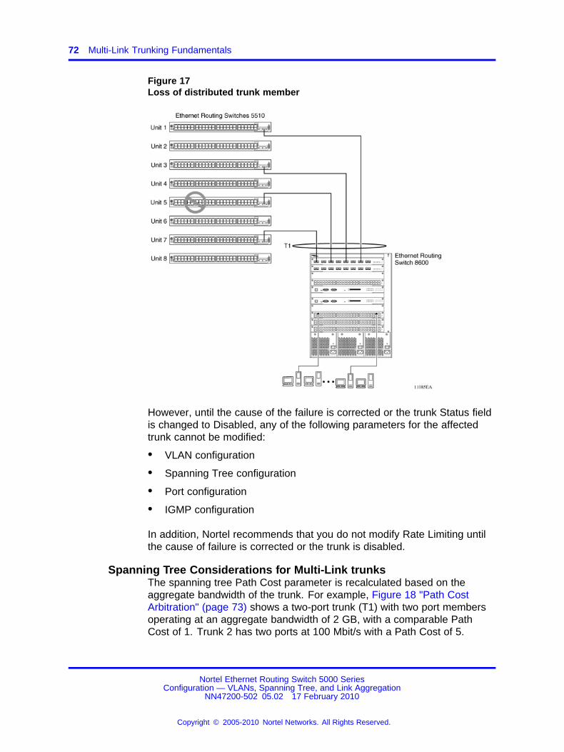
72 Multi-Link Trunking Fundamentals
Figure 17Loss of distributed trunk member
However, until the cause of the failure is corrected or the trunk Status fieldis changed to Disabled, any of the following parameters for the affectedtrunk cannot be modified:
• VLAN configuration
• Spanning Tree configuration
• Port configuration
• IGMP configuration
In addition, Nortel recommends that you do not modify Rate Limiting untilthe cause of failure is corrected or the trunk is disabled.
Spanning Tree Considerations for Multi-Link trunksThe spanning tree Path Cost parameter is recalculated based on theaggregate bandwidth of the trunk. For example, Figure 18 "Path CostArbitration" (page 73) shows a two-port trunk (T1) with two port membersoperating at an aggregate bandwidth of 2 GB, with a comparable PathCost of 1. Trunk 2 has two ports at 100 Mbit/s with a Path Cost of 5.
Nortel Ethernet Routing Switch 5000 SeriesConfiguration — VLANs, Spanning Tree, and Link Aggregation
NN47200-502 05.02 17 February 2010
Copyright © 2005-2010 Nortel Networks. All Rights Reserved.
.

Multi-Link trunks 73
When the Path Cost calculations for both trunks are equal, the softwarechooses the trunk containing the lowest numbered port as the forwardingpath.
Note: The default spanning tree Path Cost for all gigabit ports is alwaysequal to 1.Be careful when configuring trunks so as to not add onegigabit link physically in front of another trunk; the trunk will be blockedbecause they both have a Path Cost of 1.
Figure 18Path Cost Arbitration
The switch can also detect trunk member ports that are physicallymisconfigured. For example, in Figure 19 "Correctly Configured Trunk"(page 74), trunk member ports 2, 4, and 6 of Switch S1 are configuredcorrectly to trunk member ports 7, 9, and 11 of Switch S2. The SpanningTree Port Configuration screen for each switch shows the port state fieldfor each port in the Forwarding state.
Nortel Ethernet Routing Switch 5000 SeriesConfiguration — VLANs, Spanning Tree, and Link Aggregation
NN47200-502 05.02 17 February 2010
Copyright © 2005-2010 Nortel Networks. All Rights Reserved.
.

74 Multi-Link Trunking Fundamentals
Figure 19Correctly Configured Trunk
Note: Cost varies with port speed. For example, the cost for a 1 Gbit/sport is 1, while the cost for a 100 Mbit/s port is 3.
If trunk member port 11 of root Switch S2 is physically disconnected andthen reconnected to port 13, the Spanning Tree Port Configuration screenfor Switch S1 changes to show port 6 in the Blocking state (Figure 20"Detecting a Misconfigured Port" (page 75))
Nortel Ethernet Routing Switch 5000 SeriesConfiguration — VLANs, Spanning Tree, and Link Aggregation
NN47200-502 05.02 17 February 2010
Copyright © 2005-2010 Nortel Networks. All Rights Reserved.
.

Multi-Link trunks 75
Figure 20Detecting a Misconfigured Port
Note: If the port speed is 100 Mbit/s, then the STP cost for trunkmembers on S2 is 5.
Port membership in Multi-Link TrunkingWhen a Multi-Link trunk is created, the individual trunk members (thespecific ports that make up the trunk) logically connect and react as asingle entity. For example, if you change spanning tree parameters forany trunk member, the spanning tree parameters for all trunk memberschange.
To change port membership in Multi-Link Trunking:
1. Disable the trunk.
2. Make the change.
3. Reenable the trunk.
Nortel Ethernet Routing Switch 5000 SeriesConfiguration — VLANs, Spanning Tree, and Link Aggregation
NN47200-502 05.02 17 February 2010
Copyright © 2005-2010 Nortel Networks. All Rights Reserved.
.

76 Multi-Link Trunking Fundamentals
All configured trunks are indicated in the Spanning Tree Configurationscreen. The Trunk field lists the active trunks, adjacent to the portnumbers that correspond to the specific trunk member for that trunk.
When you change a Spanning Tree parameter for one trunk member, themodification affects all trunk members.
The trunk is also viewed by management stations as a single spanningtree port. The spanning tree port is represented by the trunk member withthe lowest port number. For example, if ports 13, 14, 15, and 16 are trunkmembers of trunk T1, the management station views trunk T1 as spanningtree port 13.
SMLTThis section describes the Split Multi-Link Trunking (SMLT) feature andincludes the following topics:
• “Overview” (page 76)
• “Advantages of SMLT” (page 77)
• “How does SMLT work?” (page 78)
• “Triangle SMLT configuration” (page 78)
• “Square SMLT configuration” (page 84)
• “SMLT in stack configuration” (page 99)
• “SLT” (page 104)
• “Using SMLT with SLT” (page 105)
• “SMLT and SLT Configuration steps” (page 107)
OverviewSplit Multi-Link Trunking (SMLT) is an extension of MLT that allows edgeswitches using MLT to dual-home to two SMLT aggregation switches.SMLT is transparent to the edge switches supporting MLT. In addition tolink failure protection and flexible bandwidth scaling, SMLT improves thelevel of Layer 2/Layer 3 resiliency by providing nodal protection.
Because SMLT inherently avoids loops, SMLT networks do not require theuse of IEEE 802.1D Spanning Tree protocols to enable loop free triangletopologies.
SMLT avoids loops by allowing two aggregation switches to appearas a single device to edge switches, which are dual-homed to theaggregation switches. The aggregation switches are interconnected usingan Inter-Switch Trunk (IST), which allows them to exchange addressing
Nortel Ethernet Routing Switch 5000 SeriesConfiguration — VLANs, Spanning Tree, and Link Aggregation
NN47200-502 05.02 17 February 2010
Copyright © 2005-2010 Nortel Networks. All Rights Reserved.
.

SMLT 77
and state information (permitting rapid fault detection and forwarding pathmodification). Although SMLT is primarily designed for Layer 2, it alsoprovides benefits for Layer 3 networks as well.
ATTENTIONFor SMLT to function properly, you must manually disable STP on all SMLT,IST, and SLT ports in all spanning tree groups or instances to which the portsbelong. You must also disable STP on all edge switch MLT ports that areconnected to the SMLT or SLT.
SMLT is supported on standalone units or in a stack. You can configure amaximum of 31 SMLT trunks on one device.
SMLT is supported on standalone or stacked units in triangle, square, orfull mesh configuration (see Figure 21 "SMLT in triangle configuration"(page 78) and Figure 23 "SMLT in square configuration" (page 84)) andon stacks in triangle configuration.
You cannot configure SMLT data when SMLT is running. To modify anSLT or SMLT, you must disable SMLT on that port or trunk. As well, in thisrelease, IGMP over SMLT is not supported.
Note 1: The Ethernet Routing Switch 5000 Series does not supportLACP (IEEE 802.3ad) over SMLT. Layer 2 Edge switches must supportMulti-Link Trunking to allow communications with SMLT aggregationswitches.
Note 2: To enable SMLT on the Ethernet Routing Switch 5000 Series,you must first enable Global IP Routing.
Note 3: With release 5.0 software and above, PIM-SM is not supportedover an IST link.
Advantages of SMLTSMLT improves the reliability of Layer 2 networks that operate betweenuser access switches and the network center aggregation switch byproviding:
• Load sharing among all links
• Fast failover in case of link failures
• Elimination of single point of failure
• Fast recovery in case of nodal failure
• A transparent and interoperable solution
• Removal of STP convergence issues
Nortel Ethernet Routing Switch 5000 SeriesConfiguration — VLANs, Spanning Tree, and Link Aggregation
NN47200-502 05.02 17 February 2010
Copyright © 2005-2010 Nortel Networks. All Rights Reserved.
.

78 Multi-Link Trunking Fundamentals
SMLT compared to Spanning Tree ProtocolNetworks that are designed with non-SMLT access switches dual-homedto two aggregation switches have the following design constraints:
• Spanning Tree must be used to detect loops
• No load sharing exists over redundant links
• Slow network convergence exists in case of failure
SMLT helps eliminate all single points of failure and, unlike STP, createsmultiple paths from all access switches to the core of the network.Furthermore, in case of failure, SMLT recovers as quickly as possible sothat no unused capacity is created. Finally, SMLT provides a transparentand interoperable solution that requires no modification on the part of themajority of existing user access devices.
How does SMLT work?SMLT can be set up in triangle or square configuration. All configurationsof SMLT rely on pairs of aggregation switches connected by IST links.These links are usually MLT or DMLT links.
Triangle SMLT configurationTriangle SMLT configuration requires one pair of aggregation switches asshown in Figure 21 "SMLT in triangle configuration" (page 78). TriangleSMLT can be set up with standalone switches or in a stack configuration.
Figure 21SMLT in triangle configuration
Nortel Ethernet Routing Switch 5000 SeriesConfiguration — VLANs, Spanning Tree, and Link Aggregation
NN47200-502 05.02 17 February 2010
Copyright © 2005-2010 Nortel Networks. All Rights Reserved.
.

SMLT 79
Detailed configuration example for SMLT triangle configurationThe following illustration and command set provides an example of SMLTtriangle configuration.
Figure 22SMLT triangle configuration
Table 17SMLT triangle configuration
VLAN Components
VLAN10 DUT1 10.10.10.2DUT2 10.10.10.3VRRPIP1 10.10.10.1PC1: 10.10.10.5
VLAN100 DUT1 100.100.100.3DUT2 100.100.100.2VRRPIP2 100.100.100.1PC2: 100.100.100.5
VLAN200 DUT1: 200.200.200.1DUT2: 200.200.200.2
VLAN20 DUT2: 20.20.20.1PC3: 20.20.20.5
Configure DUT1
vlan create 10 type port
vlan create 100 type port
vlan create 200 type port
vlan port 1/20,2/5,1/16,3/22,2/15 tag enable
Nortel Ethernet Routing Switch 5000 SeriesConfiguration — VLANs, Spanning Tree, and Link Aggregation
NN47200-502 05.02 17 February 2010
Copyright © 2005-2010 Nortel Networks. All Rights Reserved.
.

80 Multi-Link Trunking Fundamentals
vlan mem add 100 1/20,1/16,2/5
vlan mem add 200 1/16,2/5
vlan mem add 10 2/15,3/22,1/16,2/5
vlan mem rem 1 1/20,2/5,1/16,3/22,2/15
ip routing
in vlan 200
ip add 200.200.200.1 255.255.255.0
exit
in vlan 10
ip add 10.10.10.2 255.255.255.0
exit
in vlan 100
ip add 100.100.100.3 255.255.255.0
exit
mlt 10 ena mem 2/15,3/22
mlt spanning-tree 10 stp all learning disable
mlt 30 ena mem 1/16,2/5
mlt spanning-tree 30 stp all learning disable
in mlt 30
ist peer-ip 200.200.200.2
ist vlan 200
ist ena
exit
in mlt 10
smlt 10
exit
in fast 1/20
smlt 20
exit
Nortel Ethernet Routing Switch 5000 SeriesConfiguration — VLANs, Spanning Tree, and Link Aggregation
NN47200-502 05.02 17 February 2010
Copyright © 2005-2010 Nortel Networks. All Rights Reserved.
.

SMLT 81
in vlan 100
ip vrrp address 1 100.100.100.1
ip vrrp 1 enable backup-master enable
ip ospf enable
exit
in vlan 10
ip vrrp address 2 10.10.10.1
ip vrrp 2 enable backup-master enable
ip ospf enable
exit
in vlan 200
ip ospf enable
exit
router vrrp ena
router ospf ena
Configure DUT2.
vlan create 10 type port
vlan create 100 type port
vlan create 200 type port
vlan create 20 type port
vlan port 2/10,4/5,3/15,1/10,2/3 tag enable
vlan mem add 200 4/5,3/15
vlan mem add 10 2/3,1/10,4/5,3/15
vlan mem rem 1 2/10,4/5,3/15,1/10,2/3
vlan mem rem 1 4/3
vlan mem add 20 4/3
vlan port 4/3 pvid 20
ip routing
in vlan 200
ip add 200.200.200.2 255.255.255.0
exit
Nortel Ethernet Routing Switch 5000 SeriesConfiguration — VLANs, Spanning Tree, and Link Aggregation
NN47200-502 05.02 17 February 2010
Copyright © 2005-2010 Nortel Networks. All Rights Reserved.
.

82 Multi-Link Trunking Fundamentals
in vlan 10
ip add 10.10.10.3 255.255.255.0
exit
in vlan 100
ip add 100.100.100.2 255.255.255.0
exit
in vlan 20
ip add 20.20.20.1 255.255.255.0
exit
mlt 10 ena mem 2/3,1/10
mlt spanning-tree 10 stp all learning disable
mlt 30 ena mem 4/5,3/15
mlt spanning-tree 30 stp all learning disable
in mlt 30
ist peer-ip 200.200.200.1
ist vlan 200
ist ena
exit
in mlt 10
smlt 10
exit
in fast 2/20
smlt 20
exit
in vlan 100
ip vrrp address 1 100.100.100.1
ip vrrp 1 enable backup-master enable
ip ospf enable
exit
Nortel Ethernet Routing Switch 5000 SeriesConfiguration — VLANs, Spanning Tree, and Link Aggregation
NN47200-502 05.02 17 February 2010
Copyright © 2005-2010 Nortel Networks. All Rights Reserved.
.

SMLT 83
in vlan 10
ip vrrp address 1 10.10.10.1
ip vrrp 2 enable backup-master enable
ip ospf enable
exit
in vlan 200
ip ospf enable
exit
in vlan 20
ip ospf enable
exit
router vrrp ena
router ospf ena
Configure DUT3.
vlan create 10 type port
vlan port 1/11,2/10,2/12,3/20 tag enable
vlan mem add 10 1/11,2/10,2/12,3/20
vlan mem rem 1 1/11,2/10,2/12,3/20,3/10
vlan mem add 10 3/10
vlan port 3/10 pvid 10
mlt 10 ena mem 1/11,2/10,2/12,3/20
mlt spanning-tree 10 stp all learning disable
Configure DUT4.
vlan create 10 type port
vlan port 1/20,2/10 tag enable
vlan mem add 100 1/20,2/10
vlan mem rem 1 1/20,2/10,1/10
vlan mem add 100 1/10
vlan port 1/10 pvid 100
mlt 20 ena mem 1/20,2/10
Nortel Ethernet Routing Switch 5000 SeriesConfiguration — VLANs, Spanning Tree, and Link Aggregation
NN47200-502 05.02 17 February 2010
Copyright © 2005-2010 Nortel Networks. All Rights Reserved.
.

84 Multi-Link Trunking Fundamentals
mlt spanning-tree 20 stp all learning disable
Note: Valid license should be present on aggregation DUTs: DUT1and DUT2.
Square SMLT configurationSquare SMLT configuration requires two pairs of aggregation switchesconnected back to back (see Figure 23 "SMLT in square configuration"(page 84)). Square configuration supports standalone switches.
Figure 23SMLT in square configuration
Detailed configuration example for SMLT in squareconfigurationThe following three diagrams describe the setup of SMLT in squareconfiguration using VRRP for L3 routing. All devices are assumed to be5000 Series devices.
Nortel Ethernet Routing Switch 5000 SeriesConfiguration — VLANs, Spanning Tree, and Link Aggregation
NN47200-502 05.02 17 February 2010
Copyright © 2005-2010 Nortel Networks. All Rights Reserved.
.

SMLT 85
Vlan 20 comprises Edge Device 1, SMLT 1 ports (MLT 1 ports) on ‘A’ and‘B’ and the IST Ports (MLT 3 ports) on ‘A’ and ‘B’.
Vlan 30 comprises Edge Device 2, SMLT 3 ports (MLT 1 ports) on ‘C’ and‘D’ and IST Ports (MLT 3 ports ) on ‘C’ and ‘D’.
Vlan 40 comprises SMLT 2 ports on ‘A’, ‘B’, ‘C’, ‘D’ (MLT 2 ports) and ISTports (MLT 3 ports) on ‘A’, ‘B’, ‘C’, ‘D’.
IST Vlans (vlan 10 and all IST switches) have not been mentioned in figure1 since they are internal to the system. These comprise only the IST portsin each IST switch.
IST ports on all switches need to be tagged ports. SMLT ports may betagged or untagged.
Each of the IST switches will be running 2 VRRP instances.
• On switches ‘A’ and ‘B’, one VRRP instance will be running for Vlan 20(VRID 20) and one for Vlan 40 (VRID 41).
• On switches ‘C’ and ‘D’, one VRRP instance will be running for Vlan 30(VRID 30) and one for Vlan 40 (VRID 42).
• On switches ‘A’ and ‘B’, VRIP 40.0.0.42 (VRIP on ‘C’ and ‘D’) will bethe next hop to reach the 30.0.0.0/24 network.
• On switches ‘C’ and ‘D’, VRIP 40.0.0.41 (VRIP on ‘A’ and ‘B’) will bethe next hop to reach the 20.0.0.0/24 network.
Additionally, backup-master needs to be enabled on all switches for allVRs.
If MLTs or ports are part of multiple Vlans, ensure that their PVID is setappropriately.
Nortel Ethernet Routing Switch 5000 SeriesConfiguration — VLANs, Spanning Tree, and Link Aggregation
NN47200-502 05.02 17 February 2010
Copyright © 2005-2010 Nortel Networks. All Rights Reserved.
.

86 Multi-Link Trunking Fundamentals
Figure 24Square VRRP SMLT setup. Vlans and VRRP (IST vlans not indicated)
Nortel Ethernet Routing Switch 5000 SeriesConfiguration — VLANs, Spanning Tree, and Link Aggregation
NN47200-502 05.02 17 February 2010
Copyright © 2005-2010 Nortel Networks. All Rights Reserved.
.

SMLT 87
Figure 25Square VRRP SMLT setup. SMLTs and ISTs
Nortel Ethernet Routing Switch 5000 SeriesConfiguration — VLANs, Spanning Tree, and Link Aggregation
NN47200-502 05.02 17 February 2010
Copyright © 2005-2010 Nortel Networks. All Rights Reserved.
.

88 Multi-Link Trunking Fundamentals
Figure 26Square VRRP SMLT setup. Interface and VRRP IP addresses
The following paragraphs provide the configuration commands.
enable
configure terminal
vlan members remove 1 all
vlan create 20 type port
vlan members add 20 all
mlt 1 enable members 5-8 learning disable
enable
Nortel Ethernet Routing Switch 5000 SeriesConfiguration — VLANs, Spanning Tree, and Link Aggregation
NN47200-502 05.02 17 February 2010
Copyright © 2005-2010 Nortel Networks. All Rights Reserved.
.

SMLT 89
configure terminal
vlan members remove 1 all
vlan create 30 type port
vlan members add 30 all
mlt 1 enable members 5-8 learning disable
enable
configure terminal
vlan configcontrol autopvid
ip routing
router vrrp enable
vlan create 10 type port
vlan members add 10 3,4,5,6
interface vlan 10
ip address 10.0.0.2 255.255.255.0
exit
vlan port 3,4,5,6 tagging enable pvid 10
mlt 3 enable members 3,4,5,6 learning disable
interface mlt 3
ist enable peer-ip 10.0.0.1 vlan 10
exit
vlan create 20 type port
vlan members add 20 3,4,5,6,13,14
interface vlan 20
ip address 20.0.0.2 255.255.255.0
ip vrrp address 20 20.0.0.100
ip vrrp 20 enable backup-master enable
exit
mlt 1 enable members 13,14 learning disable
interface mlt 1
smlt 1
Nortel Ethernet Routing Switch 5000 SeriesConfiguration — VLANs, Spanning Tree, and Link Aggregation
NN47200-502 05.02 17 February 2010
Copyright © 2005-2010 Nortel Networks. All Rights Reserved.
.

90 Multi-Link Trunking Fundamentals
exit
vlan create 40 type port
vlan members add 40 3,4,5,6,17,18
interface vlan 40
ip address 40.0.0.4 255.255.255.0
ip vrrp address 41 40.0.0.41
ip vrrp 41 enable backup-master enable
exit
mlt 2 enable members 17,18 learning disable
interface mlt 2
smlt 2
exit
ip route 30.0.0.0 255.255.255.0 40.0.0.42 1
enable
configure terminal
vlan configcontrol autopvid
ip routing
router vrrp enable
vlan create 10 type port
vlan members add 10 3,4,5,6
interface vlan 10
ip address 10.0.0.1 255.255.255.0
exit
vlan port 3,4,5,6 tagging enable pvid 10
mlt 3 enable members 3,4,5,6 learning disable
interface mlt 3
ist enable peer-ip 10.0.0.2 vlan 10
exit
vlan create 20 type port
vlan members add 20 3,4,5,6,13,14
Nortel Ethernet Routing Switch 5000 SeriesConfiguration — VLANs, Spanning Tree, and Link Aggregation
NN47200-502 05.02 17 February 2010
Copyright © 2005-2010 Nortel Networks. All Rights Reserved.
.

SMLT 91
interface vlan 20
ip address 20.0.0.1 255.255.255.0
ip vrrp address 20 20.0.0.100
ip vrrp 20 enable backup-master enable
exit
mlt 1 enable members 13,14 learning disable
interface mlt 1
smlt 1
exit
vlan create 40 create type port
vlan members add 40 3,4,5,6,17,18
interface vlan 40
ip address 40.0.0.3 255.255.255.0
ip vrrp address 41 40.0.0.41
ip vrrp 41 enable backup-master enable
exit
mlt 2 enable members 17,18 learning disable
interface mlt 2
smlt 2
exit
ip route 30.0.0.0 255.255.255.0 40.0.0.42 1
enable
configure terminal
vlan configcontrol autopvid
ip routing
router vrrp enable
vlan create 10 type port
vlan members add 10 3,4,5,6
interface vlan 10
ip address 5.0.0.1 255.255.255.0
Nortel Ethernet Routing Switch 5000 SeriesConfiguration — VLANs, Spanning Tree, and Link Aggregation
NN47200-502 05.02 17 February 2010
Copyright © 2005-2010 Nortel Networks. All Rights Reserved.
.

92 Multi-Link Trunking Fundamentals
exit
vlan port 3,4,5,6 tagging enable pvid 10
mlt 3 enable members 3,4,5,6 learning disable
interface mlt 3
ist enable peer-ip 5.0.0.2 vlan 10
exit
vlan create 30 type port
vlan members add 30 3,4,5,6,13,14
interface vlan 30
ip address 30.0.0.1 255.255.255.0
ip vrrp address 30 30.0.0.100
ip vrrp 30 enable backup-master enable
exit
mlt 1 enable members 13,14 learning disable
interface mlt 1
smlt 1
exit
vlan create 40 create type port
vlan members add 40 3,4,5,6,17,18
interface vlan 40
ip address 40.0.0.2 255.255.255.0
ip vrrp address 42 40.0.0.42
ip vrrp 42 enable backup-master enable
exit
mlt 2 enable members 17,18 learning disable
interface mlt 2
smlt 2
exit
ip route 20.0.0.0 255.255.255.0 40.0.0.41 1
enable
Nortel Ethernet Routing Switch 5000 SeriesConfiguration — VLANs, Spanning Tree, and Link Aggregation
NN47200-502 05.02 17 February 2010
Copyright © 2005-2010 Nortel Networks. All Rights Reserved.
.

SMLT 93
configure terminal
vlan configcontrol autopvid
ip routing
router vrrp enable
vlan create 10 type port
vlan members add 10 3,4,5,6
interface vlan 10
ip address 5.0.0.2 255.255.255.0
exit
vlan port 3,4,5,6 tagging enable pvid 10
mlt 3 enable members 3,4,5,6 learning disable
interface mlt 3
ist enable peer-ip 5.0.0.1 vlan 10
exit
vlan create 30 type port
vlan members add 30 3,4,5,6,13,14
interface vlan 30
ip address 30.0.0.2 255.255.255.0
ip vrrp address 30 30.0.0.100
ip vrrp 30 enable backup-master enable
exit
mlt 1 enable members 13,14 learning disable
interface mlt 1
smlt 1
exit
vlan create 40 create type port
vlan members add 40 3,4,5,6,17,18
interface vlan 40
ip address 40.0.0.1 255.255.255.0
ip vrrp address 42 40.0.0.42
ip vrrp 42 enable backup-master enable
Nortel Ethernet Routing Switch 5000 SeriesConfiguration — VLANs, Spanning Tree, and Link Aggregation
NN47200-502 05.02 17 February 2010
Copyright © 2005-2010 Nortel Networks. All Rights Reserved.
.

94 Multi-Link Trunking Fundamentals
exit
mlt 2 enable members 17,18 learning disable
interface mlt 2
smlt 2
exit
ip route 20.0.0.0 255.255.255.0 40.0.0.41 1
SMLT in full mesh configurationThe following section outlines the setup of SMLT in a full meshconfiguration and provides the configuration commands.
enable
configure terminal
vlan members remove 1 all
vlan create 20 type port
vlan members add 20 all
mlt 1 enable members 5-8 learning disable
enable
configure terminal
vlan members remove 1 all
vlan create 30 type port
vlan members add 30 all
mlt 1 enable members 5-8 learning disable
enable
configure terminal
vlan configcontrol autopvid
ip routing
router vrrp enable
vlan create 10 type port
vlan members add 10 3,4,5,6
interface vlan 10
ip address 10.0.0.2 255.255.255.0
Nortel Ethernet Routing Switch 5000 SeriesConfiguration — VLANs, Spanning Tree, and Link Aggregation
NN47200-502 05.02 17 February 2010
Copyright © 2005-2010 Nortel Networks. All Rights Reserved.
.

SMLT 95
exit
vlan port 3,4,5,6 tagging enable pvid 10
mlt 3 enable members 3,4,5,6 learning disable
interface mlt 3
ist enable peer-ip 10.0.0.1 vlan 10
exit
vlan create 20 type port
vlan members add 20 3,4,5,6,13,14
interface vlan 20
ip address 20.0.0.2 255.255.255.0
ip vrrp address 20 20.0.0.100
ip vrrp 20 enable backup-master enable
exit
mlt 1 enable members 13,14 learning disable
interface mlt 1
smlt 1
exit
vlan create 40 type port
vlan members add 40 3,4,5,6,17,18,19,20
interface vlan 40
ip address 40.0.0.4 255.255.255.0
ip vrrp address 41 40.0.0.41
ip vrrp 41 enable backup-master enable
exit
mlt 2 enable members 17,18,19,20 learning disable
interface mlt 2
smlt 2
exit
ip route 30.0.0.0 255.255.255.0 40.0.0.42 1
enable
Nortel Ethernet Routing Switch 5000 SeriesConfiguration — VLANs, Spanning Tree, and Link Aggregation
NN47200-502 05.02 17 February 2010
Copyright © 2005-2010 Nortel Networks. All Rights Reserved.
.

96 Multi-Link Trunking Fundamentals
configure terminal
vlan configcontrol autopvid
ip routing
router vrrp enable
vlan create 10 type port
vlan members add 10 3,4,5,6
interface vlan 10
ip address 10.0.0.1 255.255.255.0
exit
vlan port 3,4,5,6 tagging enable pvid 10
mlt 3 enable members 3,4,5,6 learning disable
interface mlt 3
ist enable peer-ip 10.0.0.2 vlan 10
exit
vlan create 20 type port
vlan members add 20 3,4,5,6,13,14
interface vlan 20
ip address 20.0.0.1 255.255.255.0
ip vrrp address 20 20.0.0.100
ip vrrp 20 enable backup-master enable
exit
mlt 1 enable members 13,14 learning disable
interface mlt 1
smlt 1
exit
vlan create 40 create type port
vlan members add 40 3,4,5,6,17,18,19,20
interface vlan 40
ip address 40.0.0.3 255.255.255.0
ip vrrp address 41 40.0.0.41
ip vrrp 41 enable backup-master enable
Nortel Ethernet Routing Switch 5000 SeriesConfiguration — VLANs, Spanning Tree, and Link Aggregation
NN47200-502 05.02 17 February 2010
Copyright © 2005-2010 Nortel Networks. All Rights Reserved.
.

SMLT 97
exit
mlt 2 enable members 17,18,19,20 learning disable
interface mlt 2
smlt 2
exit
ip route 30.0.0.0 255.255.255.0 40.0.0.42 1
enable
configure terminal
vlan configcontrol autopvid
ip routing
router vrrp enable
vlan create 10 type port
vlan members add 10 3,4,5,6
interface vlan 10
ip address 5.0.0.1 255.255.255.0
exit
vlan port 3,4,5,6 tagging enable pvid 10
mlt 3 enable members 3,4,5,6 learning disable
interface mlt 3
ist enable peer-ip 5.0.0.2 vlan 10
exit
vlan create 30 type port
vlan members add 30 3,4,5,6,13,14
interface vlan 30
ip address 30.0.0.1 255.255.255.0
ip vrrp address 30 30.0.0.100
ip vrrp 30 enable backup-master enable
exit
mlt 1 enable members 13,14 learning disable
interface mlt 1
Nortel Ethernet Routing Switch 5000 SeriesConfiguration — VLANs, Spanning Tree, and Link Aggregation
NN47200-502 05.02 17 February 2010
Copyright © 2005-2010 Nortel Networks. All Rights Reserved.
.

98 Multi-Link Trunking Fundamentals
smlt 1
exit
vlan create 40 create type port
vlan members add 40 3,4,5,6,17,18,19,20
interface vlan 40
ip address 40.0.0.2 255.255.255.0
ip vrrp address 42 40.0.0.42
ip vrrp 42 enable backup-master enable
exit
mlt 2 enable members 17,18,19,20 learning disable
interface mlt 2
smlt 2
exit
ip route 20.0.0.0 255.255.255.0 40.0.0.41 1
enable
configure terminal
vlan configcontrol autopvid
ip routing
router vrrp enable
vlan create 10 type port
vlan members add 10 3,4,5,6
interface vlan 10
ip address 5.0.0.2 255.255.255.0
exit
vlan port 3,4,5,6 tagging enable pvid 10
mlt 3 enable members 3,4,5,6 learning disable
interface mlt 3
ist enable peer-ip 5.0.0.1 vlan 10
exit
vlan create 30 type port
Nortel Ethernet Routing Switch 5000 SeriesConfiguration — VLANs, Spanning Tree, and Link Aggregation
NN47200-502 05.02 17 February 2010
Copyright © 2005-2010 Nortel Networks. All Rights Reserved.
.

SMLT 99
vlan members add 30 3,4,5,6,13,14
interface vlan 30
ip address 30.0.0.2 255.255.255.0
ip vrrp address 30 30.0.0.100
ip vrrp 30 enable backup-master enable
exit
mlt 1 enable members 13,14 learning disable
interface mlt 1
smlt 1
exit
vlan create 40 create type port
vlan members add 40 3,4,5,6,17,18,19,20
interface vlan 40
ip address 40.0.0.1 255.255.255.0
ip vrrp address 42 40.0.0.42
ip vrrp 42 enable backup-master enable
exit
mlt 2 enable members 17,18,19,20 learning disable
interface mlt 2
smlt 2
exit
ip route 20.0.0.0 255.255.255.0 40.0.0.41 1
SMLT in stack configurationThe SMLT aggregation switches can be a single switch or a stack. Thereis no restriction on the number of units in the SMLT stack, but for betterrecovery in case of failure, the stack should contain at least three units.If you use a stack of just two units, one unit leaving the stack leaves twoisolated single units because all IST, SMLT, and SLT ports on these twounits will be disabled. For fastest recovery, SMLT should have at least onelink connected to the base unit.
In a stack, the SMLT can be active only on the base unit or the temporarybase unit, and it is solely responsible for the peer to peer switchcommunication. In stack mode, only the base unit or the temporary base
Nortel Ethernet Routing Switch 5000 SeriesConfiguration — VLANs, Spanning Tree, and Link Aggregation
NN47200-502 05.02 17 February 2010
Copyright © 2005-2010 Nortel Networks. All Rights Reserved.
.

100 Multi-Link Trunking Fundamentals
unit can take ownership of the SMLT IST operations. The base unitkeeps the master copy of the SMLT configuration and propagates theconfiguration during the data exchange cycle as it forms a stack. The baseunit distributes the following information to the non-base unit:
• peer IP address
• IST MLT ID
• IST VLAN ID
• SMLT port information
• SLT port information
Each nonbase unit will get the SMLT configuration data from the base unitand will save it to its own NVRAM.
When a new unit joins the stack, the following checks must be successful:
• SMLT settings on the base unit can be configured on the new unit.
• The SMLT configuration programmed on the unit matches the SMLTconfiguration programmed on the base unit.
• The IST trunk is still enabled and active on the stack.
If one or more of these checks is not successful, the SMLT application willstop running, but SMLT will still be administratively enabled.
When a unit leaves the stack, SMLT will stop running on that unit and IST,SMLT and SLT will be disabled on all ports. The base unit will relay all ofthe resulting port down events to its SMLT peer.
When one unit in the stack becomes inactive, the stack responds asfollows:
• If the base unit becomes inactive, the temporary base will take over.
• If a nonbase unit becomes inactive, the base unit will notify the rest ofthe stack with a list of all SMLT and SLT ports lost.
• If all of the IST ports were on the inactive unit, SMLT will stop running.
5000 Series switches as SMLT aggregation switchesThe following figure illustrates an SMLT configuration with a pair ofEthernet Routing Switch 5000 Series devices (E and F) operating asaggregation switches. Also included are four separate user accessswitches (A, B, C, and D).
Nortel Ethernet Routing Switch 5000 SeriesConfiguration — VLANs, Spanning Tree, and Link Aggregation
NN47200-502 05.02 17 February 2010
Copyright © 2005-2010 Nortel Networks. All Rights Reserved.
.

SMLT 101
Figure 275000 Series switches as SMLT aggregation switches
Refer to the following sections for a description of the components shownin this SMLT example:
• “Inter-switch trunks (IST) ” (page 101)
• “Other SMLT aggregation switch connections ” (page 102)
Inter-switch trunks (IST)The implementation of SMLT only requires two SMLT-capable aggregationswitches. User access switches B and C do not support SMLT. They areconnected to the aggregation switches E and F using standard Multi-Link
Nortel Ethernet Routing Switch 5000 SeriesConfiguration — VLANs, Spanning Tree, and Link Aggregation
NN47200-502 05.02 17 February 2010
Copyright © 2005-2010 Nortel Networks. All Rights Reserved.
.

102 Multi-Link Trunking Fundamentals
trunks split between the two aggregation switches. To support this SMLTconfiguration, the aggregation switches must be connected through anInter-switch trunk (IST).
ATTENTIONFor SMLT to function properly, you must manually disable STP on all SMLT,IST, and SLT ports in all spanning tree groups or instances to which the portsbelong. You must also disable STP on all edge switch MLT ports that areconnected to the SMLT or SLT.
Aggregation switches use the IST to:
• Confirm that they are alive and exchange MAC address forwardingtables.
• Send traffic between single switches attached to the aggregationswitches.
• Serve as a backup if one SMLT link fails.
Because the IST is required for the proper operation of the SMLT, youmust use multiple links aggregated in an IST MLT to ensure reliability andhigh availability.
When you set IST links between two 5000 Series devices, the switchesmust be running the identical software version.
Nortel also recommends that IST-linked switches run identical hardware.When the hardware is the same at both ends, you can more easily modifyand maintain the IST configurations.
You can configure IST links on mixed 5000 Series hardware; however, inthis case be sure that both devices have matching IST configurations.
5000 Series IST links cannot be partnered with Ethernet Routing Switch8000 devices.
ATTENTIONThe Ethernet Routing Switch 5510 does not support IST MLTs configured withmultiple STGs. To configure an IST with multiple STGs, you must use either theEthernet Routing Switch 5520 or 5530.
In addition to the IST VLAN, IST ports must also belong to all SMLTVLANs (as well as any other non-SMLT VLANs that require the IST tocarry traffic between the switches.) As a result, IST ports must be taggedports because they span these multiple VLANs.
Other SMLT aggregation switch connectionsIn this example, a, b1, b2, c1, c2, and d are clients and printers, while eand f can be servers or routers.
Nortel Ethernet Routing Switch 5000 SeriesConfiguration — VLANs, Spanning Tree, and Link Aggregation
NN47200-502 05.02 17 February 2010
Copyright © 2005-2010 Nortel Networks. All Rights Reserved.
.

SMLT 103
User-access switches B and C can use any method for determining whichlink of their Multi-Link trunk connections to use for forwarding a packet,as long as the same link is used for a given Source Address/DestinationAddress (SA/DA) pair. This is true, regardless of whether the DA is knownby B or C. SMLT aggregation switches always send traffic directly to auser access switch and only use the IST for traffic that they cannot forwardin another more direct way.
The examples that follow explain the process in more detail.
• “Example 1- Traffic flow from a to b1 or b2 ” (page 103)
• “Example 2- Traffic flow from b1/b2 to c1/c2 ” (page 103)
• “Example 3- Traffic flow from a to d ” (page 103)
• “Example 4- Traffic flow from f to c1/c2 ” (page 103)
Example 1- Traffic flow from a to b1 or b2Assuming a and b1/b2 are communicating through Layer 2, traffic flowsfrom A to switch E and is then forwarded over the direct link from switchE to B. Traffic coming from b1 or b2 to a is sent by B on one of its MLTports.
B can send traffic from b1 to a on the link to switch E, and send traffic fromb2 to a on the link to F. In the case of traffic from b1, switch E forwardsthe traffic directly to switch A, while traffic from b2, which arrives at F, isforwarded across the IST to E and then on to A.
Example 2- Traffic flow from b1/b2 to c1/c2Traffic from b1/b2 to c1/c2 is always sent by switch B down its MLT tothe core. No matter which switch (E or F) the traffic arrives at, the switchdirects traffic to C through the local link.
Example 3- Traffic flow from a to dTraffic from a to d and vice versa is forwarded across the IST because itis the shortest path. This path is treated purely as a standard link with noaccount taken of SMLT or the fact that the link is an IST.
Example 4- Traffic flow from f to c1/c2Traffic from f to c1/c2 is sent out directly from F. Return traffic from c1/c2can flow directly to f if switch C forwards the traffic to F. Otherwise, thereturn traffic passes across the IST after switch C sends it down the linkto E.
Nortel Ethernet Routing Switch 5000 SeriesConfiguration — VLANs, Spanning Tree, and Link Aggregation
NN47200-502 05.02 17 February 2010
Copyright © 2005-2010 Nortel Networks. All Rights Reserved.
.

104 Multi-Link Trunking Fundamentals
SLTWith Single Link Trunking (SLT) you can configure a split Multi-Link trunkusing a single port. The single port SLT behaves like an MLT-based SMLTand can coexist with SMLTs in the same system. With SLT, you can scalethe number of split Multi-Link trunks on a switch to the maximum numberof available ports.
ATTENTIONFor SMLT to function properly, you must manually disable STP on all SMLT,IST, and SLT ports in all spanning tree groups or instances to which the portsbelong. You must also disable STP on all edge switch MLT ports that areconnected to the SMLT or SLT.
SMLT and SLT links can exist in the following combinations on the SMLTaggregation switch pair:
• MLT-based SMLT + MLT-based SMLT
• MLT-based SMLT + SLT
• SLT + SLT
Rules for configuring SLTs:
• The dual-homed device connected to the aggregation switches mustbe capable of supporting MLT.
• Each SLT is assigned an SMLT ID from 1 to 512. (The actual numberof SLTs is limited only by the number of available ports on the device,minus two that must be reserved for the IST connection. For example,with a 48-port unit, you can configure a maximum of 46 SLTs.)
• SLT ports can be designated as Access or Trunk (that is, IEEE 802.1Qtagged or not tagged) and changing the type does not affect theirbehavior.
• You cannot change an SLT into an MLT-based SMLT by adding moreports. You must first delete the SLT, and then reconfigure the port asSMLT/MLT.
• You cannot change an MLT-based SMLT into a SLT by deleting allports but one. You must first remove the SMLT, delete the MLT, andthen reconfigure the port as an SLT.
• A port cannot be configured as an MLT-based SMLT and as an SLT atthe same time.
Figure 28 "SLT example" (page 105)shows a configuration in which bothaggregation switches have single port SLTs with the same IDs. Thisconfiguration allows as many SLTs, as available ports exist on the switch.
Nortel Ethernet Routing Switch 5000 SeriesConfiguration — VLANs, Spanning Tree, and Link Aggregation
NN47200-502 05.02 17 February 2010
Copyright © 2005-2010 Nortel Networks. All Rights Reserved.
.

SMLT 105
Figure 28SLT example
Using SMLT with SLTYou can configure a split trunk with an SLT on one side and anMLT-based SMLT on the other. Both must have the same SMLT ID. Inaddition to general use, Figure 29 "Changing a split trunk from MLT-basedSMLT to SLT" (page 106) shows how this configuration can be used forupgrading an MLT-based SMLT to an SLT without taking down the splittrunk.
Nortel Ethernet Routing Switch 5000 SeriesConfiguration — VLANs, Spanning Tree, and Link Aggregation
NN47200-502 05.02 17 February 2010
Copyright © 2005-2010 Nortel Networks. All Rights Reserved.
.

106 Multi-Link Trunking Fundamentals
Figure 29Changing a split trunk from MLT-based SMLT to SLT
ATTENTIONWhen you perform the steps listed in Figure 29 "Changing a split trunk fromMLT-based SMLT to SLT" (page 106) and you remove the MLT-based SMLTs(steps 2 and 4), physically disable the ports by removing the cables or byshutting the ports down using the NNCLI. Otherwise, because STP is disabledon the ports, a loop can form as soon as the SMLT is removed.
Nortel Ethernet Routing Switch 5000 SeriesConfiguration — VLANs, Spanning Tree, and Link Aggregation
NN47200-502 05.02 17 February 2010
Copyright © 2005-2010 Nortel Networks. All Rights Reserved.
.

SMLT 107
SMLT and SLT Configuration stepsTo enable SMLTs, ISTs, and SLTs on the 5000 Series switches, you mustcomplete the following steps in the order indicated.
ATTENTIONFor SMLT to function properly, you must manually disable STP on all SMLT,IST, and SLT ports in all spanning tree groups or instances to which the portsbelong. You must also disable STP on all edge switch MLT ports that areconnected to the SMLT or SLT.
Step Action
1 Configure VLANs, including port membership, VLAN IP, and porttagging.
2 Configure STP groups:
a Create STP groups.
b Assign VLAN membership.
c Enable STP groups.
d Set STP port participation.
3 Enable Global IP Routing on the devices (always required).
4 If the switches are to be used for Layer 3 routing, enable VRRPon the units (required for Layer 3 only).
5 Configure MLTs on the devices:
a Create MLT groups by assigning trunk members.
b Disable STP participation on all trunk member ports.
c Enable the MLTs.
6 Configure SMLTs on the devices:
a Assign the Peer IP address and VLAN ID to the IST MLT.
b Enable the IST.
c Create the SMLTs.
d Create the SLTs (if applicable).
7 Make IST connections and ensure IST session is running.
8 Make SMLT/SLT connections and check SMLT/SLT status.
--End--
Note: These are the recommended steps for a new installation. Forexisting networks, perform steps 1 through 6 as closely as possible. Tominimize loops, you can perform step 5 before steps 1 through 4.
Nortel Ethernet Routing Switch 5000 SeriesConfiguration — VLANs, Spanning Tree, and Link Aggregation
NN47200-502 05.02 17 February 2010
Copyright © 2005-2010 Nortel Networks. All Rights Reserved.
.

108 Multi-Link Trunking Fundamentals
To disable SMLTs and SLTs, perform the same steps in reverse order.
SMLT configuration example with VRRP and OSPFFigure 30 "SMLT configuration example with VRRP and OSPF" (page108) shows an example of aggregation switches configured with SMLT,VRRP, and OSPF. For more information on VRRP and OSPF, seeNortel Ethernet Routing Switch 5000 Series Configuration — IP RoutingProtocols () (NN47200-503).
Figure 30SMLT configuration example with VRRP and OSPF
To configure the example shown in Figure 30 "SMLT configurationexample with VRRP and OSPF" (page 108), you must perform thefollowing tasks:
Nortel Ethernet Routing Switch 5000 SeriesConfiguration — VLANs, Spanning Tree, and Link Aggregation
NN47200-502 05.02 17 February 2010
Copyright © 2005-2010 Nortel Networks. All Rights Reserved.
.

SMLT 109
Step Action
1 Create VLANs 3, 4, and 5.
2 Set ports 1-5 as tagging.
3 Assign ports 1 and 2 to VLAN 3.
4 Assign ports 1, 2 and 3 to VLAN 4.
5 Assign ports 1, 2, 4 and 5 to VLAN 5.
6 Set VLAN 3 IP to 3.3.3.1 .
7 Set VLAN 4 IP to 4.4.4.1 .
8 Set VLAN 5 IP to 5.5.5.1 .
9 Enable IP routing globally.
10 Create MLT 3 with ports 1 and 2.
11 Disable STP on ports 1 and 2.
12 Set IST = MLT 3, Peer IP=3.3.3.2, VLAN 3.
13 Disable STP on port 3 and configure it as SLT with SMLT ID 4.
14 Create MLT 5 with ports 4 to 5.
15 Disable STP on ports 4 to 5.
16 Set MLT 5 as SMLT 5.
17 Enable VRRP globally.
18 Enable VRRP on VLAN 4 with VRID 4 and VRIP 4.4.4.254.
19 Enable VRRP back up master.
20 Enable VRRP on VLAN 5 with VRID 5 and VRIP 5.5.5.254.
21 Enable VRRP back up master.
22 Enable OSPF globally.
23 Enable OSPF on VLANs 3,4 and 5.
--End--
Step Action
1 Create VLANs 3, 4, and 5.
2 Set ports 1 to 5 as tagging.
3 Assign ports 1 and 2 to VLAN 3.
4 Assign ports 1, 2 and 3 to VLAN 4.
Nortel Ethernet Routing Switch 5000 SeriesConfiguration — VLANs, Spanning Tree, and Link Aggregation
NN47200-502 05.02 17 February 2010
Copyright © 2005-2010 Nortel Networks. All Rights Reserved.
.

110 Multi-Link Trunking Fundamentals
5 Assign ports 1, 2, 4 and 5 to VLAN 5.
6 Set VLAN 3 IP to 3.3.3.2.
7 Set VLAN 4 IP to 4.4.4.2.
8 Set VLAN 5 IP to 5.5.5.2.
9 Enable IP routing.
10 Create MLT 3 with ports 1 and 2.
11 Disable STP on ports 1 and 2.
12 Set IST = MLT 3, Peer IP=3.3.3.1, VLAN 3.
13 Disable STP on port 3 and configure it as SLT with SMLT ID 4.
14 Create MLT 5 with ports 4 to 5.
15 Disable STP on ports 4 to 5.
16 Set MLT 5 as SMLT 5.
17 Enable VRRP globally.
18 Enable VRRP on VLAN 4 with VRID 4 and VRIP 4.4.4.254.
19 Enable VRRP back up master.
20 Enable VRRP on VLAN 5 with VRID 5 and VRIP 5.5.5.254.
21 Enable VRRP back up master.
22 Enable OSPF globally.
23 Enable OSPF on VLAN 3, 4, and 5
--End--
Step Action
1 Create Vlan 4.
2 Assign ports 3 to 4 to Vlan 4.
3 Create MLT 4 with ports 3 to 4.
4 Disable STP on MLT 4.
--End--
Step Action
1 Create Vlan 5.
2 Assign ports 3 to 6 to Vlan 5.
Nortel Ethernet Routing Switch 5000 SeriesConfiguration — VLANs, Spanning Tree, and Link Aggregation
NN47200-502 05.02 17 February 2010
Copyright © 2005-2010 Nortel Networks. All Rights Reserved.
.

SMLT 111
3 Create MLT 5 with ports 3 to 6.
4 Disable STP on MLT 5.
--End--
Nortel Ethernet Routing Switch 5000 SeriesConfiguration — VLANs, Spanning Tree, and Link Aggregation
NN47200-502 05.02 17 February 2010
Copyright © 2005-2010 Nortel Networks. All Rights Reserved.
.

112 Multi-Link Trunking Fundamentals
Detailed configuration commands5520-48T-PWR(config)#vlan create 3 type port5520-48T-PWR(config)#vlan create 4 type port5520-48T-PWR(config)#vlan create 5 type port5520-48T-PWR(config)#vlan port 1-5 tagging enable5520-48T-PWR(config)#vlan member add 3 1-25520-48T-PWR(config)#vlan member add 4 1-25520-48T-PWR(config)#vlan member add 5 1-25520-48T-PWR(config)#vlan member remove 1 1-55520-48T-PWR(config)#vlan member add 4 35520-48T-PWR(config)#vlan member add 5 4,55520-48T-PWR(config)#ip routing
5520-48T-PWR(config)#interface vlan 35520-48T-PWR(config-if)#ip routing5520-48T-PWR(config-if)#ip address 3.3.3.1 255.255.255.05520-48T-PWR(config-if)#exit
5520-48T-PWR(config)#interface vlan 45520-48T-PWR(config-if)#ip routing5520-48T-PWR(config-if)#ip address 4.4.4.1 255.255.255.05520-48T-PWR(config-if)#exit
5520-48T-PWR(config)#interface vlan 55520-48T-PWR(config-if)#ip routing5520-48T-PWR(config-if)#ip address 5.5.5.1 255.255.255.05520-48T-PWR(config-if)#exit
5520-48T-PWR(config)#mlt 3 member 1-25520-48T-PWR(config)#mlt spanning-tree 3 stp all learning disable5520-48T-PWR(config)#mlt 3 enable5520-48T-PWR(config)#interface mlt 35520-48T-PWR(config-if)#ist enable peer-ip 3.3.3.2 vlan 35520-48T-PWR(config-if)#exit
5520-48T-PWR(config)#interface fastEthernet 35520-48T-PWR(config-if)#spanning-tree learning disable5520-48T-PWR(config-if)#smlt 45520-48T-PWR(config-if)#exit
5520-48T-PWR(config)#mlt 5 member 4-55520-48T-PWR(config)#mlt spanning-tree 5 stp all learning disable5520-48T-PWR(config)#mlt 5 enable5520-48T-PWR(config-if)#interface mlt 55520-48T-PWR(config-if)#smlt 55520-48T-PWR(config-if)#exit
Nortel Ethernet Routing Switch 5000 SeriesConfiguration — VLANs, Spanning Tree, and Link Aggregation
NN47200-502 05.02 17 February 2010
Copyright © 2005-2010 Nortel Networks. All Rights Reserved.
.

SMLT 113
5520-48T-PWR(config)#router vrrp enable5520-48T-PWR(config)#router ospf enable5520-48T-PWR(config)#interface vlan 45520-48T-PWR(config-if)#ip vrrp address 4 4.4.4.2545520-48T-PWR(config-if)#ip vrrp 4 enable backup-master enable5520-48T-PWR(config-if)#ip ospf enable5520-48T-PWR(config-if)#exit5520-48T-PWR(config)#interface vlan 55520-48T-PWR(config-if)#ip vrrp address 5 5.5.5.2545520-48T-PWR(config-if)#ip vrrp 5 enable backup-master enable5520-48T-PWR(config-if)#ip ospf enable5520-48T-PWR(config-if)#exit
Nortel Ethernet Routing Switch 5000 SeriesConfiguration — VLANs, Spanning Tree, and Link Aggregation
NN47200-502 05.02 17 February 2010
Copyright © 2005-2010 Nortel Networks. All Rights Reserved.
.

114 Multi-Link Trunking Fundamentals
5520-48T-PWR(config)#vlan create 3 type port5520-48T-PWR(config)#vlan create 4 type port5520-48T-PWR(config)#vlan create 5 type port5520-48T-PWR(config)#vlan port 1-5 tagging enable5520-48T-PWR(config)#vlan member add 3 1-25520-48T-PWR(config)#vlan member add 4 1-25520-48T-PWR(config)#vlan member add 5 1-25520-48T-PWR(config)#vlan member remove 1 1-55520-48T-PWR(config)#vlan member add 4 35520-48T-PWR(config)#vlan member add 5 4,55520-48T-PWR(config)#ip routing
5520-48T-PWR(config)#interface vlan 35520-48T-PWR(config-if)#ip routing5520-48T-PWR(config-if)#ip address 3.3.3.2 255.255.255.05520-48T-PWR(config-if)#exit
5520-48T-PWR(config)#interface vlan 45520-48T-PWR(config-if)#ip routing5520-48T-PWR(config-if)#ip address 4.4.4.2 255.255.255.05520-48T-PWR(config-if)#exit
5520-48T-PWR(config)#interface vlan 55520-48T-PWR(config-if)#ip routing5520-48T-PWR(config-if)#ip address 5.5.5.2 255.255.255.05520-48T-PWR(config-if)#exit
5520-48T-PWR(config)#mlt 3 member 1-25520-48T-PWR(config)#mlt spanning-tree 3 stp all learning disable5520-48T-PWR(config)#mlt 3 enable5520-48T-PWR(config)#interface mlt 35520-48T-PWR(config-if)#ist enable peer-ip 3.3.3.1 vlan 35520-48T-PWR(config-if)#exit
5520-48T-PWR(config)#interface fastEthernet 35520-48T-PWR(config-if)#spanning-tree learning disable5520-48T-PWR(config-if)#smlt 45520-48T-PWR(config-if)#exit
5520-48T-PWR(config)#mlt 5 member 4-55520-48T-PWR(config)#mlt spanning-tree 5 stp all learning disable5520-48T-PWR(config)#mlt 5 enable5520-48T-PWR(config-if)#interface mlt 55520-48T-PWR(config-if)#smlt 55520-48T-PWR(config-if)#exit
Nortel Ethernet Routing Switch 5000 SeriesConfiguration — VLANs, Spanning Tree, and Link Aggregation
NN47200-502 05.02 17 February 2010
Copyright © 2005-2010 Nortel Networks. All Rights Reserved.
.

SMLT 115
5520-48T-PWR(config)#router vrrp enable5520-48T-PWR(config)#router ospf enable5520-48T-PWR(config)#interface vlan 45520-48T-PWR(config-if)#ip vrrp address 4 4.4.4.2545520-48T-PWR(config-if)#ip vrrp 4 enable backup-master enable5520-48T-PWR(config-if)#ip ospf enable5520-48T-PWR(config-if)#exit5520-48T-PWR(config)#interface vlan 55520-48T-PWR(config-if)#ip vrrp address 5 5.5.5.2545520-48T-PWR(config-if)#ip vrrp 5 enable backup-master enable5520-48T-PWR(config-if)#ip ospf enable5520-48T-PWR(config-if)#exit
5510-48T(config)#vlan create 4 type port5510-48T(config)#vlan port 3-4 tagging enable5510-48T(config)#vlan member add 4 3-45510-24T(config)#mlt 4 member 3-45510-24T(config)#mlt spanning-tree 4 stp all learning disable5510-24T(config)#mlt 4 enable
5510-48T(config)#vlan create 5 type port5510-48T(config)#vlan port 3-6 tagging enable5510-48T(config)#vlan member add 5 3-65510-24T(config)#mlt 5 member 3-65510-24T(config)#mlt spanning-tree 5 stp all learning disable5510-24T(config)#mlt 5 enable
SLT configuration example with VRRP and OSPFFigure 31 "SLT configuration example with VRRP and OSPF" (page116)shows an example of aggregation switches configured with SLT,VRRP and OSPF. For more information on VRRP and OSPF, seeNortel Ethernet Routing Switch 5000 Series Configuration — IP RoutingProtocols () (NN47200-503).
Nortel Ethernet Routing Switch 5000 SeriesConfiguration — VLANs, Spanning Tree, and Link Aggregation
NN47200-502 05.02 17 February 2010
Copyright © 2005-2010 Nortel Networks. All Rights Reserved.
.

116 Multi-Link Trunking Fundamentals
Figure 31SLT configuration example with VRRP and OSPF
To configure the example shown in Figure 31 "SLT configuration examplewith VRRP and OSPF" (page 116), you must perform the following tasks.
Step Action
1 Create VLANs 3, 4, and 5.
2 Set ports 1 to 5 as tagging.
3 Assign ports 1 and 2 to VLAN 3.
4 Assign ports 1, 2 and 4 to VLAN 4.
5 Assign ports 1, 2, and 5 to VLAN 5.
6 Set VLAN 3 IP to 3.3.3.1 .
7 Set VLAN 4 IP to 4.4.4.1 .
8 Set VLAN 5 IP to 5.5.5.1 .
Nortel Ethernet Routing Switch 5000 SeriesConfiguration — VLANs, Spanning Tree, and Link Aggregation
NN47200-502 05.02 17 February 2010
Copyright © 2005-2010 Nortel Networks. All Rights Reserved.
.

SMLT 117
9 Enable IP routing globally.
10 Create MLT 3 with ports 1-2.
11 Disable STP on ports 1-2.
12 Set IST = MLT 3, Peer IP=3.3.3.2, VLAN 3.
13 Disable STP on port 5.
14 Set port 5 as SLT 5.
15 Enable VRRP globally
16 Enable VRRP on VLAN 4 with VRID 4 and VRIP 4.4.4.254.
17 Enable VRRP back up master.
18 Enable VRRP on VLAN 5 with VRID 5 and VRIP 5.5.5.254 .
19 Enable VRRP back up master.
20 Enable OSPF globally.
21 Enable OSPF on VLANs 3,4 and 5.
--End--
Step Action
1 Create VLANs 3, 4, and 5.
2 Set ports 1 to 5 as tagging.
3 Assign ports 1 and 2 to VLAN 3.
4 Assign ports 1, 2 and 4 to Vlan 4.
5 Assign ports 1, 2 and 5 to Vlan 5.
6 Set Vlan 3 IP to 3.3.3.2.
7 Set Vlan 4 IP to 4.4.4.2.
8 Set Vlan 5 IP to 5.5.5.2.
9 Enable IP routing.
10 Create MLT 3 with ports 1 and 2.
11 Disable STP on ports 1 and 2.
12 Set IST = MLT 3, Peer IP=3.3.3.1, Vlan 3.
13 Disable STP on port 5.
14 Set port 5 as SLT 5.
15 Enable VRRP globally.
16 Enable VRRP on Vlan 4 with VRID 4 and VRIP 4.4.4.254.
Nortel Ethernet Routing Switch 5000 SeriesConfiguration — VLANs, Spanning Tree, and Link Aggregation
NN47200-502 05.02 17 February 2010
Copyright © 2005-2010 Nortel Networks. All Rights Reserved.
.

118 Multi-Link Trunking Fundamentals
17 Enable VRRP back up master.
18 Enable VRRP on Vlan 5 with VRID 5 and VRIP 5.5.5.254.
19 Enable VRRP back up master.
20 Enable OSPF globally.
21 Enable OSPF on Vlan 3, 4 and 5.
--End--
Step Action
1 Create Vlan 4.
2 Assign ports 5 to 7 to Vlan 4.
3 Create Vlan 5.
4 Assign ports 5 to 7 to Vlan 5.
5 Create MLT 5 with ports 5 to 6
--End--
Detailed configuration commandsThe following sections describe the detailed NNCLI commands requiredto carry out the configuration described in Figure 31 "SLT configurationexample with VRRP and OSPF" (page 116)
Nortel Ethernet Routing Switch 5000 SeriesConfiguration — VLANs, Spanning Tree, and Link Aggregation
NN47200-502 05.02 17 February 2010
Copyright © 2005-2010 Nortel Networks. All Rights Reserved.
.

SMLT 119
5520-48T-PWR(config)#vlan create 3 type port5520-48T-PWR(config)#vlan create 4 type port5520-48T-PWR(config)#vlan create 5 type port5520-48T-PWR(config)#vlan port 1,2,4,5 tagging enable5520-48T-PWR(config)#vlan member add 3 1-25520-48T-PWR(config)#vlan member add 4 1-2,45520-48T-PWR(config)#vlan member add 5 1,2,55520-48T-PWR(config)#vlan member remove 1 1-55520-48T-PWR(config)#ip routing
5520-48T-PWR(config)#interface vlan 35520-48T-PWR(config-if)#ip routing5520-48T-PWR(config-if)#ip address 3.3.3.1 255.255.255.05520-48T-PWR(config-if)#exit
5520-48T-PWR(config)#interface vlan 45520-48T-PWR(config-if)#ip routing5520-48T-PWR(config-if)#ip address 4.4.4.1 255.255.255.05520-48T-PWR(config-if)#exit
5520-48T-PWR(config)#interface vlan 55520-48T-PWR(config-if)#ip routing5520-48T-PWR(config-if)#ip address 5.5.5.1 255.255.255.05520-48T-PWR(config-if)#exit
5520-48T-PWR(config)#mlt 3 member 1-25520-48T-PWR(config)#mlt spanning-tree 3 stp all learning disable5520-48T-PWR(config)#mlt 3 enable5520-48T-PWR(config)#interface mlt 35520-48T-PWR(config-if)#ist enable peer-ip 3.3.3.2 vlan 35520-48T-PWR(config-if)#exit
5520-48T-PWR(config)#interface fastEthernet 55520-48T-PWR(config-if)#spanning-tree learning disable5520-48T-PWR(config-if)#smlt 5 5520-48T-PWR(config-if)#exit
5520-48T-PWR(config)#router vrrp enable5520-48T-PWR(config)#router ospf enable 5520-48T-PWR(config)#interface vlan 45520-48T-PWR(config-if)#ip vrrp address 4 4.4.4.2545520-48T-PWR(config-if)#ip vrrp 4 enable backup-master enable5520-48T-PWR(config-if)#ip ospf enable 5520-48T-PWR(config-if)#exit5520-48T-PWR(config)#interface vlan 55520-48T-PWR(config-if)#ip vrrp address 5 5.5.5.2545520-48T-PWR(config-if)#ip vrrp 5 enable backup-master enable5520-48T-PWR(config-if)#ip ospf enable5520-48T-PWR(config-if)#exit
Nortel Ethernet Routing Switch 5000 SeriesConfiguration — VLANs, Spanning Tree, and Link Aggregation
NN47200-502 05.02 17 February 2010
Copyright © 2005-2010 Nortel Networks. All Rights Reserved.
.

120 Multi-Link Trunking Fundamentals
5520-48T-PWR(config)#vlan create 3 type port5520-48T-PWR(config)#vlan create 4 type port5520-48T-PWR(config)#vlan create 5 type port5520-48T-PWR(config)#vlan port 1-5 tagging enable5520-48T-PWR(config)#vlan member add 3 1-25520-48T-PWR(config)#vlan member add 4 1,2,45520-48T-PWR(config)#vlan member add 5 1,2,55520-48T-PWR(config)#vlan member remove 1 1-55520-48T-PWR(config)#ip routing
5520-48T-PWR(config)#interface vlan 35520-48T-PWR(config-if)#ip routing5520-48T-PWR(config-if)#ip address 3.3.3.2 255.255.255.05520-48T-PWR(config-if)#exit
5520-48T-PWR(config)#interface vlan 45520-48T-PWR(config-if)#ip routing5520-48T-PWR(config-if)#ip address 4.4.4.2 255.255.255.05520-48T-PWR(config-if)#exit
5520-48T-PWR(config)#interface vlan 55520-48T-PWR(config-if)#ip routing5520-48T-PWR(config-if)#ip address 5.5.5.2 255.255.255.05520-48T-PWR(config-if)#exit
5520-48T-PWR(config)#mlt 3 member 1-25520-48T-PWR(config)#mlt spanning-tree 3 stp all learning disable5520-48T-PWR(config)#mlt 3 enable5520-48T-PWR(config)#interface mlt 35520-48T-PWR(config-if)#ist enable peer-ip 3.3.3.1 vlan 35520-48T-PWR(config-if)#exit
5520-48T-PWR(config)#interface fastEthernet 55520-48T-PWR(config-if)#spanning-tree learning disable5520-48T-PWR(config-if)#smlt 55520-48T-PWR(config-if)#exit
5520-48T-PWR(config)#router vrrp enable5520-48T-PWR(config)#router ospf enable5520-48T-PWR(config)#interface vlan 45520-48T-PWR(config-if)#ip vrrp address 4 4.4.4.2545520-48T-PWR(config-if)#ip vrrp 4 enable backup-master enable5520-48T-PWR(config-if)#ip ospf enable5520-48T-PWR(config-if)#exit5520-48T-PWR(config)#interface vlan 55520-48T-PWR(config-if)#ip vrrp address 5 5.5.5.2545520-48T-PWR(config-if)#ip vrrp 5 enable backup-master enable5520-48T-PWR(config-if)#ip ospf enable5520-48T-PWR(config-if)#exit
Nortel Ethernet Routing Switch 5000 SeriesConfiguration — VLANs, Spanning Tree, and Link Aggregation
NN47200-502 05.02 17 February 2010
Copyright © 2005-2010 Nortel Networks. All Rights Reserved.
.

IEEE 802.3ad Link Aggregation 121
5510-48T(config)#vlan create 5 type port5510-48T(config)#vlan member add 5 5-75510-48T(config)#vlan port 5-6 tagging enable5510-48T(config)#vlan member remove 1 5-75510-24T(config)#mlt 5 member 5-65510-24T(config)#mlt spanning-tree 5 stp all learning disable5510-24T(config)#mlt 5 enable
SLPPSimple Loop Prevention Protocol (SLPP) is a new feature designedto detect loops in a SMLT network. Not intended to replace STP as acomprehensive loop detection mechanism, SLPP acts as a secondarymechanism for detection and prevention of looping in a SMLT environmentand can only be configured on SMLT networks. Since SMLT requires thatSTP be disabled on IST, SMLT and SLT ports for normal operation, loopsmay be introduced to a network. SLPP was designed to prevent suchloops and resulting traffic disruptions.
When enabled, SLPP causes the switch to send a periodic SLPP PDU onthe transmitting VLAN at a user defined or default (500 ms) transmissioninterval. If a loop is active in the network, the SLPP PDU is returned tothe switch and the affected port is shutdown after the specified number ofPDU has been received (Default is 5). If a port is shutdown as the resultof a detected loop, it must be manually returned to an active state by thenetwork administrator unless auto enable is configured. SLPP only sendsa PDU to VLANs specified in the transmitting list configured by the user.
Note: When configured in addition to STP, STP operation will takeprecedence leaving SLPP as a supplementary measure for loopdetection.
IEEE 802.3ad Link AggregationWith IEEE 802.3ad-based link aggregation, you can aggregate one ormore links together to form Link Aggregation Groups (LAG) so that a MACclient can treat the Link Aggregation Group as if it were a single link. Linkaggregation increases the aggregate throughput of the interconnectionbetween the devices while also providing link redundancy.
Although IEEE 802.3ad-based link aggregation and Multi-Link Trunking(MLT) features provide similar services, MLT is statically defined, whereasIEEE 802.3ad-based link aggregation is dynamic and provides morefunctionality.
Link Aggregation Control Protocol (LACP), defined by the IEEE 802.3adstandard, allows a switch to learn the presence and capabilities of aremote switch by exchanging information with the remote switch before a
Nortel Ethernet Routing Switch 5000 SeriesConfiguration — VLANs, Spanning Tree, and Link Aggregation
NN47200-502 05.02 17 February 2010
Copyright © 2005-2010 Nortel Networks. All Rights Reserved.
.
122 Multi-Link Trunking Fundamentals
trunk group is formed. Either switch can accept or reject the aggregationrequest with the far end on a per-port basis. A link that cannot join a trunkgroup operates as an individual link.
The main purpose of LACP is to manage switch ports and their portmemberships to link aggregation trunk groups (LAGs). LACP candynamically add or remove LAG ports, depending on their availability andstates. By default, Link Aggregation is set to disabled on all ports
Link aggregation employs the following principles and concepts:
• A MAC client communicates with a set of ports through an Aggregator,which presents a standard IEEE 802.3 service interface to the MACclient. The Aggregator binds to one or more ports within a system.
• The Aggregator is responsible for distributing frame transmissions fromthe MAC client to the various ports, and to collect received frames fromthe ports and pass them to the MAC client transparently.
• A system can contain multiple aggregators, serving multiple MACclients. A given port will bind to (at most) a single Aggregator at anytime. A MAC client is served by a single Aggregator at a time.
• The binding of ports to aggregators within a system is managed by theLink Aggregation Control function for that system, which is responsiblefor determining which links can be aggregated, aggregating them,binding the ports within the system to an appropriate Aggregator, andmonitoring conditions to determine when a change in aggregation isneeded.
The network manager can control the determination and bindingdirectly through the manipulation of the state variables of LinkAggregation (for example, Keys). In addition, automatic determination,configuration, binding, and monitoring can occur through the use of aLink Aggregation Control Protocol (LACP).
The LACP uses peer exchanges across the links to determine, onan ongoing basis, the aggregation capability of the various links, andcontinuously provides the maximum level of aggregation capabilityachievable between a given pair of systems.
• Each port is assigned a unique, globally administered MAC address.
The MAC address is used as the source address for frame exchangesthat are initiated by entities within the Link Aggregation sublayer itself(for example, LACP and Marker protocol exchanges).
• Each Aggregator is assigned a unique, globally administered MACaddress, which is used as the MAC address of the aggregation fromthe perspective of the MAC Client, both as a source address fortransmitted frames and as the destination address for received frames.
Nortel Ethernet Routing Switch 5000 SeriesConfiguration — VLANs, Spanning Tree, and Link Aggregation
NN47200-502 05.02 17 February 2010
Copyright © 2005-2010 Nortel Networks. All Rights Reserved.
.

IEEE 802.3ad Link Aggregation 123
The MAC address of the Aggregator can be one of the MAC addressesof a port in the associated Link Aggregation Group.
Link aggregation rulesThe 5000 Series switch link aggregation groups operate under thefollowing rules:
• Link aggregation groups are formed using LACP.
• All ports in a link aggregation group must be connected to the samefar-end system.
• All ports in a link aggregation group must be operating in full-duplexmode.
• All ports in a link aggregation group must be configured to the sameport speed.
• All ports in a link aggregation group must be in the same VLANs.
• In stack mode, ports in a link aggregation group can be on differentunits to form a distributed LAG (DLAG).
• LACPDUs are transmitted and received on all ports in the linkaggregation group.
• Link aggregation is compatible with the Spanning Tree Protocol (STP).
• Link aggregation group(s) must be in the same STP groups.
• STP BPDUs are transmitted and received only on the first link in thegroup.
• A maximum of 32 link aggregation groups are supported.
• A maximum of 8 active links are supported per LAG.
• Unlimited standby links that are supported per LAG (for example, if aswitch or stack is configured with one LAG, all nonactive LAG link portscan be configured as standby ports for that LAG).
The maximum number of LAGs is 32, and the maximum number of activelinks per group is eight. Link Aggregation allows more than eight links tobe configured in one LAG. The first eight high-priority links are active links,and together, they form a trunk group. The ninth low-priority link remains instandby mode. When one of the active links goes down, the standby linkbecomes active and is added to the trunk group.
The failover process is as follows:
• The down link is removed from the trunk group.
• The highest priority standby link is added to the trunk group.
Nortel Ethernet Routing Switch 5000 SeriesConfiguration — VLANs, Spanning Tree, and Link Aggregation
NN47200-502 05.02 17 February 2010
Copyright © 2005-2010 Nortel Networks. All Rights Reserved.
.

124 Multi-Link Trunking Fundamentals
There can be a temporary delay in traffic flow due to the switching oflinks. If the active link goes down and no standby link exists, the traffic isrerouted to the remaining active links with a minimal delay in time.
LACP port modeThe IEEE 802.3ad standard specifies that links that are not successfulcandidates for aggregation (for example, links to devices that cannotperform aggregation, or links that are manually set as non-aggregatable)can continue to operate as individual LACP links. However,LACP-enabled, STP-disabled ports that operate as individual links canpotentially cause network loops.
You can specify the desired behavior of non-aggregatable LACP links onthe switch:
• Default mode: In the default mode, if an LACP-enabled port isconnected to a non-LACP partner port and the link fails to convergewith the link partner, the port state moves to the forwarding state. Thisis the standard behavior from earlier software releases. The defaultmode is compatible with standard LACP.
• Advance mode: In the Advance mode, if an LACP-enabled port isconnected to a non-LACP partner port and the link fails to convergewith the link partner, the port state remains in the blocking state. Thisbehavior is applied only to LACP-enabled ports that have STP disabledand prevents potential loops from forming in the network.
Note: The Advance mode is not compatible with IEEE 802.3 adstandard LACP.
The Advance mode is also useful when a trunk port is removed from atrunk configuration. Currently, an active LACP trunk port can be removedfrom the trunk configuration if the link partner disables LACP or if PDUreception times out. Each LACP mode handles this scenario as follows:
• Default mode: The default mode implementation removes theactive LACP trunk port from the active trunk configuration, and theport functions as a regular standalone active port. The port state isdetermined by STP when you enable STP, but is set to forwardingwhen you disable STP on the port.
• Advance mode: In the Advance mode, LACP-enabled ports that haveSTP disabled remain in the blocking state. This prevents potentialloops from forming in the network.
Nortel Ethernet Routing Switch 5000 SeriesConfiguration — VLANs, Spanning Tree, and Link Aggregation
NN47200-502 05.02 17 February 2010
Copyright © 2005-2010 Nortel Networks. All Rights Reserved.
.

125.
VLACP Fundamentals
VLACPMany enterprise networks require that trunk links provide subsecondfailover to the redundant link when a failure occurs at the local or remoteendpoint. This requirement can be met when both ends of the link areinformed of any loss of communication.
Virtual Link Aggregation Control Protocol (VLACP), an LACP extension, isa Layer 2 handshaking protocol that provides end-to-end failure detectionbetween two physical Ethernet interfaces. It allows the switch to detectunidirectional or bidirectional link failures.
Virtual LACP (VLACP) overviewWhile Ethernet has been extended to detect remote link failures throughfunctions such as Remote Fault Indication and Far End Fault Indicationmechanisms, a limitation of these functions is that they terminate atthe next Ethernet hop. Therefore, failures cannot be determined on anend-to-end basis.
Figure 32 "Problem description (1 of 2)" (page 126) provides an illustrationof these limitations. While the Enterprise networks shown can connecttheir aggregated Ethernet trunk groups through a service provider networkconnection (for example, through a VPN), far-end failures cannot besignaled with Ethernet-based functions that operate end-to-end throughthe service provider cloud.
In Figure 32 "Problem description (1 of 2)" (page 126), the MLT (betweenEnterprise switches S1 and S2) extends through the service provider (SP)network.
Nortel Ethernet Routing Switch 5000 SeriesConfiguration — VLANs, Spanning Tree, and Link Aggregation
NN47200-502 05.02 17 February 2010
Copyright © 2005-2010 Nortel Networks. All Rights Reserved.
.

126 VLACP Fundamentals
Figure 32Problem description (1 of 2)
As shown in Figure 33 "Problem description (2 of 2)" (page 127), if the L2link on S1 (S1/L2) fails, the link-down failure is not propagated over theSP network to S2. Thus, S2 continues to send traffic over the S2/L2 link,which is black-holed because the S1/L2 link has failed.
Nortel Ethernet Routing Switch 5000 SeriesConfiguration — VLANs, Spanning Tree, and Link Aggregation
NN47200-502 05.02 17 February 2010
Copyright © 2005-2010 Nortel Networks. All Rights Reserved.
.

VLACP 127
Figure 33Problem description (2 of 2)
Note that LACP, as defined by IEEE, is a protocol that exists between twobridge endpoints; therefore, the LACPDUs are terminated at the next (SP)interface.
Nortel has developed an extension to LACP, which is calledVirtual LACP (VLACP). This extension can provide an end-to-end failuredetection mechanism. With VLACP, far-end failures can be detectedallowing an MLT to fail over properly when end-to-end connectivity is notguaranteed for certain links in an aggregation group. VLACP prevents thefailure scenario shown in Figure 33 "Problem description (2 of 2)" (page127).
VLACP featuresThis section provides a summary of some of the key features of VLACP asimplemented on the Ethernet Routing Switch 5000 Series:
• VLACP is configured per port. A port can be an individual port or amember of an MLT.
• When you set VLACP parameters for a trunk port, the settings areapplied to all trunk members.
• For VLACP to operate properly, there must be a logical point-to-pointconnection (Layer 2 tunnel) between the two endpoints.
Nortel Ethernet Routing Switch 5000 SeriesConfiguration — VLANs, Spanning Tree, and Link Aggregation
NN47200-502 05.02 17 February 2010
Copyright © 2005-2010 Nortel Networks. All Rights Reserved.
.

128 VLACP Fundamentals
• VLACP does not work for point-to-multipoint connections.
• On each port that has VLACP enabled, VLACPDUs are sentperiodically. If VLACPDUs are not received on a particular link, thatlink is taken down after a configurable timeout period.
• For the current software release, VLACP is supported on Ethernetinterfaces only.
• VLACP can run independently as a port-to-port protocol or on top ofMLT or LACP protocol.
• VLACP packets are untagged because they operate at the port leveland not the VLAN level.
• The Destination Mac Address used in VLACPDUs is configurable. TheMAC Address must be a multicast MAC Address so that it is alwaysflooded. This allows the exchange of VLACPDUs from end to end.
• Both VLACP partners must have same multicast address, timers, andethertype configured for VLACP to work properly.
• A unicast MAC address (destination MAC address) can be configuredper port for end-to-end connectivity between units, when VLACPpackets travel through an ISP network.
• The VLACP PDU transmission interval changes when an LACP partneris lost. This aids detection in certain failure scenarios.
• VLACP PDU messages are processed so as to prevent false VLACPstate recovery.
• VLACP defaults to an IEEE reserved multicast MAC address forsourcing LACP PDU packets.
Troubleshooting
Error logs are created for the following failures and errors:
• An incorrect PDU, such as wrong destination MAC addresses received
• An inability to enable VLACP on a port due to unallowable DestinationMAC addresses
• A port index that is out of range
• A port was blocked by VLACP (a log message is also generated whenthe port is unblocked)
Nortel Ethernet Routing Switch 5000 SeriesConfiguration — VLANs, Spanning Tree, and Link Aggregation
NN47200-502 05.02 17 February 2010
Copyright © 2005-2010 Nortel Networks. All Rights Reserved.
.

129.
ADAC FundamentalsThe 5000 Series switch supports the Auto-Detection and Auto-Configuration (ADAC) of Nortel IP Phones. With ADAC, you can automaticallyconfigure the switch to support and prioritize IP Phone traffic.
When ADAC is enabled and a Nortel IP Phone is connected to the switch,the switch automatically configures the VLAN, port, and Quality of Service(QoS) settings necessary for the transmission of signal and voice betweenthe Nortel IP Phone and the switch.
ADAC can configure the switch whether the switch is directly connected tothe Call Server (through the Call Server port) or is indirectly connected tothe Call Server using a network uplink (through the Uplink port).
ADAC has three separate operating modes to meet the requirements ofdifferent networks:
• Untagged-Frames-Basic:
Use this mode when you want a basic configuration only and the IPPhones are sending untagged traffic.
• Untagged-Frames-Advanced:
Use this mode when you want an advanced configuration andthe IP Phones are sending untagged traffic. In this mode, ADACcreates a Voice VLAN that includes the Call Server or Uplink port, asapplicable, and all telephony ports. All tagging, PVID settings, andtraffic prioritization are configured automatically.
• Tagged Frames:
Use this mode when you want an advanced configuration and the IPPhones are sending tagged traffic. You can also use tagged framesto support devices other than IP Phones. This mode provides thesame configuration as the Untagged-Frames-Advanced mode, but withtagged frames. As with the Untagged-Frames-Advanced mode, ADACcreates a Voice VLAN that includes the Call Server or Uplink port, asapplicable, and all telephony ports. All tagging, PVID settings, andtraffic prioritization are configured automatically.
Nortel Ethernet Routing Switch 5000 SeriesConfiguration — VLANs, Spanning Tree, and Link Aggregation
NN47200-502 05.02 17 February 2010
Copyright © 2005-2010 Nortel Networks. All Rights Reserved.
.
130 ADAC Fundamentals
ADAC operationThe following sections provide detailed explanations of ADAC operation.
Auto-Detection of Nortel IP PhonesWhen a Nortel IP Phone is connected to a switch and is powered on,the switch automatically detects the IP Phone, and then begins theauto-configuration of the IP Phone. An ADAC lookup is also performedeach time a MAC address is learned, migrated, or aged-out and removed.
When you enable auto-detection on a port, the port also becomesoperationally enabled. Similarly, when you disable auto-detection on aport, the port is operationally disabled. A port can also be operationallydisabled if the port maximum of 32 devices is reached. If the portlimit is reached, a trap will be sent (if ADAC traps are enabled) andautoconfiguration will also be removed. To put the port back into theoperational state, disable and then reenable auto-detection on the affectedport. ADAC supports a maximum of 32 devices (both IP phones andnon-phones) per port.
There are two ways to use ADAC to automatically detect IP Phones. Youcan enable one or the other or both of these methods on a port-by-portbasis, as long as at least one detection mechanism remains enabled.
The detection mechanism can be selected
• before enabling auto-detection on the port, or
• if ADAC is globally disabled.
The two methods of auto-detection are by MAC address or usingLLDP (IEEE 802.1ab). Auto-detection by MAC address is based onusing predefined MAC addresses to determine that the specified portis connected to a Nortel IP phone. For more information and the list ofdefined MAC address ranges, see “Auto-Detection by MAC address” (page131).
Auto-detection by LLDP allows the system to detect IP phones with MACaddresses outside the list of default MAC address ranges as long asthey can be identified as an IP phone by LLDP, regardless of their MACaddresses. For more information about auto-detection by LLDP, see“Auto-Detection by LLDP (IEEE 802.1ab)” (page 132).
You can enable either of these detection mechanisms or both on eachindividual port. At least one of these detection methods must be enabledon each port.
Nortel Ethernet Routing Switch 5000 SeriesConfiguration — VLANs, Spanning Tree, and Link Aggregation
NN47200-502 05.02 17 February 2010
Copyright © 2005-2010 Nortel Networks. All Rights Reserved.
.

ADAC operation 131
Auto-Detection by MAC addressWhen this feature is enabled on a port, the switch checks all MACaddresses of packets received on the port. If a received MAC addressfalls within the range of known Nortel IP Phone MAC addresses, ADACdetermines that the specified port is connected to a Nortel IP Phone andinitiates the required configuration. ADAC is supported for a maximum of32 devices per port, but in most cases, there will be only one IP phoneand one PC on each port.
The 5000 Series switch has a default range of MAC addresses configuredto be recognized as Nortel IP Phones by ADAC.
Table 18 "Default ADAC MAC address ranges" (page 131)shows a list ofthe default MAC address ranges.
Table 18Default ADAC MAC address ranges
Lower End Higher End
00-0A-E4-01-10-20 00-0A-E4-01-23-A7
00-0A-E4-01-70-EC 00-0A-E4-01-84-73
00-0A-E4-01-A1-C8 00-0A-E4-01-AD-7F
00-0A-E4-01-DA-4E 00-0A-E4-01-ED-D5
00-0A-E4-02-1E-D4 00-0A-E4-02-32-5B
00-0A-E4-02-5D-22 00-0A-E4-02-70-A9
00-0A-E4-02-D8-AE 00-0A-E4-02-FF-BD
00-0A-E4-03-87-E4 00-0A-E4-03-89-0F
00-0A-E4-03-90-E0 00-0A-E4-03-B7-EF
00-0A-E4-04-1A-56 00-0A-E4-04-41-65
00-0A-E4-04-80-E8 00-0A-E4-04-A7-F7
00-0A-E4-04-D2-FC 00-0A-E4-05-48-2B
00-0A-E4-05-B7-DF 00-0A-E4-06-05-FE
00-0A-E4-06-55-EC 00-0A-E4-07-19-3B
00-0A-E4-08-0A-02 00-0A-E4-08-7F-31
00-0A-E4-08-B2-89 00-0A-E4-09-75-D8
00-0A-E4-09-BB-9D 00-0A-E4-09-CF-24
00-0A-E4-09-FC-2B 00-0A-E4-0A-71-5A
00-0A-E4-0A-9D-DA 00-0A-E4-0B-61-29
00-0A-E4-0B-BB-FC 00-0A-E4-0B-BC-0F
Nortel Ethernet Routing Switch 5000 SeriesConfiguration — VLANs, Spanning Tree, and Link Aggregation
NN47200-502 05.02 17 February 2010
Copyright © 2005-2010 Nortel Networks. All Rights Reserved.
.

132 ADAC Fundamentals
Table 18Default ADAC MAC address ranges (cont’d.)
00-0A-E4-0B-D9-BE 00-0A-E4-0C-9D-0D
00-13-65-FE-F3-2C 00-13-65-FF-ED-2B
00-15-9B-FE-A4-66 00-15-9B-FF-24-B5
00-16-CA-00-00-00 00-16-CA-01-FF-FF
00-16-CA-F2-74-20 00-16-CA-F4-BE-0F
00-17-65-F6-94-C0 00-17-65-F7-38-CF
00-17-65-FD-00-00 00-17-65-FF-FF-FF
00-18-B0-33-90-00 00-18-B0-35-DF-FF
00-19-69-83-25-40 00-19-69-85-5F-FF
You can change these default MAC address ranges using the NNCLI, DM,or Web-based management.
ADAC checks a MAC address against the supported ranges only whenthe MAC address is learned on the port. If you change the supportedMAC address ranges, this has no effect on the previously learned MACaddresses. For example, if the address of a configured device is no longerin an ADAC range, the IP phone remains configured until its MAC addressis aged out (by disconnecting the cable, for example) or until ADAC isdisabled, either globally or on the port.
In a similar fashion, if the MAC address of an IP Phone—a MAC addressthat’s not recognized by ADAC—is learned on a port and then is lateradded to the supported ranges, the IP Phone won’t be detected andconfigured until the address is aged out or ADAC is disabled. Themaximum number of ranges that ADAC supports is 128.
The maximum number of ranges that ADAC supports is 128.
Auto-Detection by LLDP (IEEE 802.1ab)Auto-detection by LLDP extends the auto-detection that relies on MACaddresses. This feature allows devices identified as IP phones throughLLDP to be detected by ADAC even if their MAC addresses are outsidethe list of ADAC MAC address ranges.
LLDP-based auto-detection supports a maximum of 16 devices per port.
Detailed configuration exampleThe following commands provide a detailed configuration example.
• Default a DUT.
• Disable on port 5 MAC detection.
Nortel Ethernet Routing Switch 5000 SeriesConfiguration — VLANs, Spanning Tree, and Link Aggregation
NN47200-502 05.02 17 February 2010
Copyright © 2005-2010 Nortel Networks. All Rights Reserved.
.

ADAC operation 133
• Enable ADAC on port 5 and globally.
• Define the uplink port, and voice VLAN port, then change operatingmode to Untagged Frames Advanced.
• Verify that above settings were applied.
• Connect your phone on port 5 and verify that it was detected andconfiguration applied.
Auto-Configuration of Nortel IP PhonesThe ADAC port participation can be set independently by enabling ordisabling ADAC for particular ports.
When a new MAC address of an IP phone is learned on a port with ADACenabled, ADAC immediately performs the auto-Configuration for that port(this operation is dependent on the configured ADAC operating mode and
Nortel Ethernet Routing Switch 5000 SeriesConfiguration — VLANs, Spanning Tree, and Link Aggregation
NN47200-502 05.02 17 February 2010
Copyright © 2005-2010 Nortel Networks. All Rights Reserved.
.

134 ADAC Fundamentals
on whether other MAC addresses are learned on that port). This includesthe required configuration of ports, VLANs, and QoS settings and involvesminimal intervention by the user.
Auto-configuration is automatically removed or applied based on the portstate, the state of the MAC addresses and the phones detected on theport.
The ports are polled every two seconds for their auto-configuration stateand to see whether or not auto-configuration should be applied based onthe current ADAC settings, both the global setting and the port setting.Auto-configuration will be applied on the port when the port is operational(operational state is enabled) and if one of these conditions is true:
• Op-mode = Untagged-Frames-Basic or Untagged-Frames-Advanced,at least one IP phone is detected on the port, and no non-IP phonesare detected on the port
• Op-mode = Tagged-Frames and at least one IP phone is detected onthe port
Auto-configuration is removed if any of these conditions becomes true:
• auto-detect becomes disabled on the port
• the ports operational state becomes disabled
• Op-mode = Untagged-Frames-Basic or -Advanced, and at least onenon-IP device is detected on the port
• there are no IP phones detected on the port and the link is down.
If the link is still up but there are no IP phones on the port,auto-configuration is disabled after an aging period of about 90 seconds.
If all MAC addresses belonging to Nortel IP Phones on a port age out, theAuto-Configuration settings are removed from the port.
Initial user settingsBefore enabling the ADAC feature, you must set the operating modeaccording to how the IP Phones are configured to send frames: taggedor untagged.
When running ADAC in Untagged-Frames-Advanced or Tagged-Framesoperating modes, you must also specify:
• the ID of the VLAN to be used for voice packets
• at least one of the following:
Nortel Ethernet Routing Switch 5000 SeriesConfiguration — VLANs, Spanning Tree, and Link Aggregation
NN47200-502 05.02 17 February 2010
Copyright © 2005-2010 Nortel Networks. All Rights Reserved.
.

ADAC operation 135
— Call Server port, if connected directly to the switch
— Uplink port, if used
Note: To properly enable the ADAC feature, the VLAN ID for theVoice-VLAN must not be a preexisting VLAN.
Tag voice traffic entering the Uplink port with the Voice VLAN ID. Thisconfiguration must be made on all switches on the path to the Call Server.
Port RestrictionsThe following restrictions apply to the Call Server, Uplink, and Telephonyports.
The Call Server port must not be:
• part of a trunk (MLT, LAG)
• a Monitor Port in port mirroring
• a NSNA port
• a Telephony port
• the Uplink port
• an EAP port
The Uplink port must not be:
• a Monitor Port in port mirroring
• an NSNA port
• a Telephony port
• an EAP port
• the Call Server port
The Telephony port must not be:
• part of a trunk (MLT, LAG)
• a Monitor Port in port mirroring
• an IGMP static router port
• an NSNA port
• the Call Server port
• the Uplink port
Nortel Ethernet Routing Switch 5000 SeriesConfiguration — VLANs, Spanning Tree, and Link Aggregation
NN47200-502 05.02 17 February 2010
Copyright © 2005-2010 Nortel Networks. All Rights Reserved.
.

136 ADAC Fundamentals
Operating modesADAC can be configured to apply settings depending on how the Nortel IPPhones are configured to send traffic (tagged or untagged) and dependingon the desired complexity level of the Auto-Configuration. The followingsections provide detailed descriptions of the configurations that are appliedin each ADAC operating mode.
• “QoS settings used by ADAC” (page 136)
• “Untagged-Frames-Basic operating mode” (page 136)
• “Untagged-Frames-Advanced operating mode” (page 137)
• “Tagged-Frames operating mode” (page 138)
QoS settings used by ADACADAC QoS configuration is applied to:
• traffic coming from the IP Phones
• traffic coming from the Call Server port
• traffic coming from the Uplink port
To configure the switch appropriately for IP Phones, the ADAC operatingmodes use two QoS policies, each associated with one of the followingclassifiers:
• all-IP-traffic
The all-IP-traffic classifier filters all IPv4 traffic and remarks it withDSCP 0x2E and 802.1p priority 0x06.
• tagged-with-VoiceVLAN-traffic
The tagged-with-VoiceVLAN-traffic classifier filters only the traffictagged with the Voice VLAN ID and remarks it with DSCP 0x2E and802.1p priority 0x06.
Untagged-Frames-Basic operating modeIn the Untagged-Frames-Basic operating mode, the Call Server and Uplinkports are not used, so QoS settings are applied only for traffic coming fromthe IP Phones. The VLAN configuration is minimal.
To properly configure the Untagged-Frames-Basic mode, you mustperform the following:
• Configure the IP Phones to send untagged frames.
• Connect only IP Phones to a port. (You cannot connect a device that isnot a Nortel IP Phone to the same port.)
Nortel Ethernet Routing Switch 5000 SeriesConfiguration — VLANs, Spanning Tree, and Link Aggregation
NN47200-502 05.02 17 February 2010
Copyright © 2005-2010 Nortel Networks. All Rights Reserved.
.

ADAC operation 137
QoS configuration
In the Untagged-Frames-Basic mode, Auto-Configuration performs thefollowing QoS configuration:
• Adds the telephony ports to the all-IP-traffic classifier (because only IPPhones are connected to the telephony ports).
VLAN configuration
In the Untagged-Frames-Basic mode, Auto-Configuration also performsthe following VLAN configuration:
• Tagging of Telephony ports is set to Untagged.
Untagged-Frames-Advanced operating modeTo properly configure the Untagged-Frames-Advanced operating mode,you must perform the following:
• Configure the IP Phones to send untagged frames.
• Connect only IP Phones to a port. (You cannot connect a device that isnot a Nortel IP Phone to the same port.)
• Specify the Voice-VLAN ID and either the Call Server port or the Uplinkport, as applicable.
• If the switch is not directly connected to the Call Server, ensure thatthe telephony packets coming from the Call Server through the Uplinkport are tagged with the Voice-VLAN ID.
QoS configuration
In the Untagged-Frames-Advanced mode, Auto-Configuration performs thefollowing QoS configuration:
• For traffic coming from the Telephony ports:
— Adds the telephony ports to the all-IP-traffic classifier (because onlyIP Phones are connected to the telephony ports).
• For traffic coming from the Call Server port (if any):
— Adds the Call Server port to the all-IP-traffic classifier (becauseonly Call Server traffic enters that port).
• For traffic coming from the Uplink port (if any):
— Adds the Uplink port to the tagged-with-VoiceVLAN-traffic classifier.(As the Uplink port connects to the network, packets with different
Nortel Ethernet Routing Switch 5000 SeriesConfiguration — VLANs, Spanning Tree, and Link Aggregation
NN47200-502 05.02 17 February 2010
Copyright © 2005-2010 Nortel Networks. All Rights Reserved.
.

138 ADAC Fundamentals
tagging can enter this port; this ensures that only voice traffic isremarked.)
VLAN configuration
In the Untagged-Frames-Advanced mode, Auto-Configuration alsoperforms the following VLAN configurations:
• Telephony port:
— Membership = adds to Voice-VLAN; removes from other VLANs(The port does not need to be a member of other VLANs.)
— Tagging = Untagged
— PVID = Voice-VLAN
• Call Server port (if any):
— Membership = adds to Voice-VLAN; not removed from otherVLANs
— Tagging = Untagged
— PVID = Voice-VLAN
• Uplink port (if any):
— Membership = adds to Voice-VLAN; not removed from otherVLANs
— Tagging = Tagged
— PVID = no change (All VLAN changes made by ADAC are as ifVCC=flexible, so the Auto-PVID setting is ignored.)
Tagged-Frames operating modeTo properly configure the Tagged-Frames operating mode, you mustperform the following:
• Configure the IP Phones to send tagged frames with the ID of theVoice-VLAN.
• Connect at least one Nortel IP Phone to a telephony port. (In thismode, other devices can be connected to the same port; for example,when a PC is connected directly to the IP phone.)
• Ensure that the Filter Unregistered Frames option is set to disabled onthe ADAC-enabled ports. (Otherwise, no source MAC address can belearned for incoming packets tagged with the Voice VLAN ID, meaningthat no phone can be detected.)
Nortel Ethernet Routing Switch 5000 SeriesConfiguration — VLANs, Spanning Tree, and Link Aggregation
NN47200-502 05.02 17 February 2010
Copyright © 2005-2010 Nortel Networks. All Rights Reserved.
.

ADAC operation 139
• Specify the Voice-VLAN ID and either the Call Server port or the Uplinkport, as applicable.
• If the switch is not directly connected to the Call Server, ensure thatthe telephony packets coming from the Call Server through the Uplinkport are tagged with the Voice-VLAN ID.
QoS configuration
In the Tagged-Frames mode, Auto-Configuration performs the followingQoS configuration:
• For traffic coming from the telephony ports:
— Adds the telephony ports to the tagged-with-VoiceVLAN-trafficclassifier. (In this way, only the voice traffic is remarked.)
• For traffic coming from the Call Server port (if any):
— Adds the Call Server port to the all-IP-traffic classifier (becauseonly Call Server traffic enters that port).
• For traffic coming from the Uplink port (if any):
— Adds the Uplink port to the tagged-with-VoiceVLAN-traffic classifier.(As the Uplink port connects to the network, packets with differenttagging can enter this port; applying this classifier ensures that onlyvoice traffic is remarked.)
In this way, all traffic tagged with the Voice-VLAN ID is prioritized.
VLAN configuration
In the Tagged-Frames mode, Auto-Configuration also performs thefollowing VLAN configurations:
• Telephony port:
— Membership = adds to Voice-VLAN; not removed from otherVLANs
— Tagging = UntagPVIDOnly
— PVID = no change or changed to Default-VLAN(1) if the currentvalue equals the Voice-VLAN (must be different from theVoice-VLAN ID)
• Call Server port (if any):
Nortel Ethernet Routing Switch 5000 SeriesConfiguration — VLANs, Spanning Tree, and Link Aggregation
NN47200-502 05.02 17 February 2010
Copyright © 2005-2010 Nortel Networks. All Rights Reserved.
.
140 ADAC Fundamentals
— Membership = adds to Voice-VLAN; not removed from otherVLANs
— Tagging = Untagged
— PVID = Voice-VLAN
• Uplink port (if any):
— Membership = adds to Voice-VLAN; not removed from otherVLANs
— Tagging = Tagged
— PVID = no change (All VLAN changes made by ADAC are as ifVCC =flexible, so the Auto-PVID setting is ignored.)
Dynamic VLAN auto-configurationThe following describes the details of the ADAC VLAN configuration:
• The ADAC Voice VLAN is created and removed automatically.
• All membership to the ADAC Voice VLAN is dynamic, meaning that thesettings are not saved to NVRAM. The dynamic settings will be lost onreboot or when ADAC is disabled.
• From the moment ADAC is enabled on a port (the port set astelephony port, Call Server port, or Uplink port), all VLAN configurationis dynamic (including user configuration). When the ADACconfiguration is removed from a port, the pre-ADAC configuration fromNVRAM is restored.
• From the moment ADAC is enabled on a port set as a telephony portor a call server port, (but not an uplink port), all VLAN configurationis dynamic (including user configuration). When removing theconfiguration for a port (for example, when changing a port so that it isno longer a call server port or a telephony port), the configuration fromNVRAM is restored. After that, the user configuration will be permanentagain. For an uplink port, any user configuration made while ADACwas enabled on the port is saved.
• For telephony ports, the NVRAM VLAN configuration is restored in twocases: when the ADAC configuration is removed due to the removal ofthe IP Phone, or when ADAC is disabled for that port.
• The VLAN Configuration Control (VCC) rules, other than those for theFlexible mode, are skipped internally by ADAC configuring VLANs. AnyVLAN settings made automatically by ADAC follow the rules of theFlexible mode, regardless of the current value of VCC. Any settings
Nortel Ethernet Routing Switch 5000 SeriesConfiguration — VLANs, Spanning Tree, and Link Aggregation
NN47200-502 05.02 17 February 2010
Copyright © 2005-2010 Nortel Networks. All Rights Reserved.
.

ADAC operation 141
that you make manually on ADAC ports follow the current VCC mode,as for a non-ADAC port.
• If you change the preset values of Tagging and PVID when ADACis running in Tagged-Frames mode, future auto-configurations willapply the new values. Changing the preset has no effect on currentconfigured Tagging and PVID values.
ADAC and stackingIn a stack, global ADAC settings of the base unit are applied acrossthe stack, except for port settings (for Call Server port, Uplink port andTelephony ports).
The ADAC port states are taken from each unit. Therefore, unit ports havethe same ADAC status in a stack as they do in standalone mode.
If two or more units each have a configured Call Server port in standalonemode and are then joined together in a stack, the Call Server port with thelowest interface number in the stack is elected as the stack Call Serverport.
This same scenario also occurs for the Uplink port.
Lost Call Server Port or Uplink PortIf ADAC is operating in either the Untagged-Frames-Advanced orTagged-Frames operating mode and you reset the unit on which the CallServer or Uplink port is located, the feature loses the valid Call Server orUplink port. In this case, the feature is temporarily disabled until the unitwith the Call Server or Uplink port rejoins the stack and the configurationbecomes valid again. While the unit is in a temporarily disabled state, theVoice-VLAN is not deleted if it was created first.
If the ADAC global configuration is changed on the base unit while thefeature is temporarily disabled, the feature stays disabled regardless ofwhere the Call Server or Uplink port are located when their unit rejoins thestack. Changing Auto-Detection on Telephony ports has no effect on theglobal settings.
Uplink port as part of MLT in a stackTo set the Uplink port to be part of a distributed MLT in a stack, you mustfirst configure and enable the MLT, and then you can set one of the MLTmembers as the Uplink port.
If the unit containing the Uplink port in a stack is removed from the stack,the lowest port from the same MLT becomes the new Uplink port.
Nortel Ethernet Routing Switch 5000 SeriesConfiguration — VLANs, Spanning Tree, and Link Aggregation
NN47200-502 05.02 17 February 2010
Copyright © 2005-2010 Nortel Networks. All Rights Reserved.
.

142 ADAC Fundamentals
After rebooting a stack, each unit that has a port member belonging to theUplink MLT is configured as an Uplink port on the unit. After joining thestack, the lowest Uplink port is elected as the stack Uplink port.
When you disable the MLT, the Uplink configuration is removed for alltrunk members except for the original Uplink port.
ADAC and LACP enabled on an Uplink portTo set the Uplink port as LACP-enabled, you must first configure andenable LACP on the port, and then you can set the port as the Uplink port.
Due to the dynamic configuration of VLANs, you are not allowed to:
• enable LACP on a preconfigured Uplink port
• enable LACP on a port with the same admin key as the ADAC Uplinkports
• change the admin key of any member of the ADAC Uplink ports
• set the admin key for a LACP-enabled port to the same value as theUplink port
When ADAC sets the configuration for the Uplink port, the VLAN and QoSconfiguration is applied for all LACP-enabled (active or passive) portsbelonging to the same LAG as the Uplink port.
Any changes to the LAG mode, from Active to Passive or from Passiveto Active, have no effect on ADAC.
Uplink port as part of LACP in a stackIn a stack, LAGs containing the Uplink port operate similarly to MLTscontaining the Uplink port.
If the unit containing the Uplink port in a stack is removed from the stack,the lowest port from the same LAG becomes the new Uplink port.
After rebooting a stack, each unit that has a port member belonging to theUplink LAG is configured as an Uplink port on the unit. After joining thestack, the lowest Uplink port is elected as the stack Uplink port.
When you disable the LAG, the Uplink configuration is removed for alltrunk members except for the original Uplink port.
After you remove the LAG, you cannot reenable the configuration for theUplink port. You must remove the Uplink, reconfigure the LAG, and thenset the Uplink port again.
Nortel Ethernet Routing Switch 5000 SeriesConfiguration — VLANs, Spanning Tree, and Link Aggregation
NN47200-502 05.02 17 February 2010
Copyright © 2005-2010 Nortel Networks. All Rights Reserved.
.

ADAC operation 143
ADAC and EAP configurationADAC and EAP are mutually exclusive on the Call Server port and theUplink port.
However, on telephony ports, you can enable both ADAC and EAP,provided the following conditions are met:
• The ports must be configured to allow non-EAP MAC addresses.
• Guest VLAN must not be allowed on the ports.
To enable ADAC on an EAP port, follow these steps.
1. On the switch, globally enable support for non-EAP MAC addresses.(In NNCLI, use the eap multihost allow-non-eap-maccommand.)
2. On each telephony port, enable support for non-EAP MACaddresses. (In NNCLI, use the eap multihost port <port>allow-non-eap-mac command.)
3. On each telephony port, enable EAP Multihost. (In NNCLI, use the eapmultihost port <port> enable command.)
4. On the telephony ports, ensure that Guest VLAN is disabled. (InNNCLI, use the show eap guest-vlan command.)
5. On the switch, enable EAP globally. (In NNCLI, use the eap enablecommand.)
6. Configure and enable ADAC on the ports.
When you configure ADAC and EAP, the following restrictions apply:
• When ADAC is enabled, you cannot enable or disable EAP or EAPMultihost on the port.
• You can enable ADAC on the port only if:
— EAP is disabled per port
OR
— EAP and Multihost are enabled per port
EAP does not change the VLAN configuration for ADAC-enabled ports.ADAC changes to the VLAN configuration take priority.
ADAC user RestrictionsAfter ADAC is enabled, you cannot:
• Delete the Voice-VLAN.
• Remove auto-configured ports from Voice-VLAN.
Nortel Ethernet Routing Switch 5000 SeriesConfiguration — VLANs, Spanning Tree, and Link Aggregation
NN47200-502 05.02 17 February 2010
Copyright © 2005-2010 Nortel Networks. All Rights Reserved.
.

144 ADAC Fundamentals
• View or remove any QoS setting made by ADAC (auto-configuredsettings).
• Set the Voice-VLAN as Management VLAN.
You can:
• Add ports to and remove ports from the Voice-VLAN. (Configurationis dynamic.)
• Change the tagging and PVID of all ports in the Voice-VLAN.(Configuration is dynamic.)
Disabling ADACDisabling the ADAC feature deletes all configurations, including theVoice-VLAN, and restores the pre-ADAC port configurations saved inNVRAM for all ADAC-enabled ports (Telephony, Call Server, and Uplink).
Nortel Ethernet Routing Switch 5000 SeriesConfiguration — VLANs, Spanning Tree, and Link Aggregation
NN47200-502 05.02 17 February 2010
Copyright © 2005-2010 Nortel Networks. All Rights Reserved.
.

145.
Configuring VLANs using the NNCLI
Creating and Managing VLANs using the NNCLIThe Command Line Interface commands detailed in this section allow forthe creation and management of VLANs. Depending on the type of VLANbeing created or managed, the command mode needed to execute thesecommands can differ.
This section contains information about the following topics:
• “Displaying VLAN information” (page 145)
• “Displaying VLAN interface information” (page 147)
• “Displaying VLAN port membership” (page 147)
• “Setting the management VLAN” (page 147)
• “Resetting the management VLAN to default” (page 147)
• “Deleting a VLAN” (page 149)
• “Modifying VLAN MAC address flooding” (page 149)
• “Configuring VLAN name” (page 150)
• “Enabling automatic PVID” (page 150)
• “Configuring VLAN port settings” (page 150)
• “Configuring VLAN members” (page 151)
• “Configuring VLAN Configuration Control” (page 152)
• “Managing the MAC address forwarding database table” (page 154)
• “IP Directed Broadcasting” (page 157)
Displaying VLAN informationUse the following procedure to display the number, name, type, protocol,user PID, state of a VLAN and whether it is a management VLAN.
Nortel Ethernet Routing Switch 5000 SeriesConfiguration — VLANs, Spanning Tree, and Link Aggregation
NN47200-502 05.02 17 February 2010
Copyright © 2005-2010 Nortel Networks. All Rights Reserved.
.

146 Configuring VLANs using the NNCLI
Procedure steps
Step Action
1 To display VLAN information, use the following command fromPrivileged EXEC mode.
show vlan [configcontrol] [dhcp-relay <1-4094>][igmp { <1-4094> | unknown-mcast-allow-flood |unknown-mcast-no-flood}] [interface { info | vids}][ip <vid>] [mgmt] [multicast < membership>] [type{port | protocol-ipEther2| protocol-ipx802.3 |protocol-ipx802.2 | protocol-ipxSnap | protocol-ipxEther2 | protocol-decEther2 | protocol-snaEther2 |protocol-Netbios | protocol-xnsEther2 | protocol-vinesEther2 | protocol-ipv6Ether2 | protocol-Userdef|protocol-RarpEther2] [vid <1-4094>]
--End--
Variable definitions
Variable Value
vid <1-4094> Enter the number of the VLAN to display.
type Enter the type of VLAN to display:
• port - port-based
• protocol - protocol-based (see following list)
protocol-ipEther2 Specifies an ipEther2 protocol-based VLAN.
protocol-ipx802.3 Specifies an ipx802.3 protocol-based VLAN.
protocol-ipx802.2 Specifies an ipx802.2 protocol-based VLAN.
protocol-ipxSnap Specifies an ipxSnap protocol-based VLAN.
protocol-ipxEther2 Specifies an ipxEther2 protocol-based VLAN.
protocol-decEther2 Specifies a decEther2 protocol-based VLAN.
protocol-snaEther2 Specifies an snaEther2 protocol-based VLAN.
protocol-Netbios Specifies a NetBIOS protocol-based VLAN.
protocol-xnsEther2 Specifies an xnsEther2 protocol-based VLAN.
protocol-vinesEther2 Specifies a vinesEther2 protocol-based VLAN.
protocol-ipv6Ether2 Specifies an ipv6Ether2 protocol-based VLAN.
protocol-Userdef Specifies a user-defined protocol-based VLAN.
protocol-RarpEther2 Specifies a RarpEther2 protocol-based VLAN.
Nortel Ethernet Routing Switch 5000 SeriesConfiguration — VLANs, Spanning Tree, and Link Aggregation
NN47200-502 05.02 17 February 2010
Copyright © 2005-2010 Nortel Networks. All Rights Reserved.
.

Creating and Managing VLANs using the NNCLI 147
Displaying VLAN interface informationUse the following procedure to display VLAN settings associated with aport, including tagging information, PVID number, priority, and filteringinformation for tagged, untagged, and unregistered frames.
Procedure steps
Step Action
1 To display VLAN interface information, use the followingcommand from Privileged EXEC mode.
show vlan interface info [<portlist>]
--End--
Displaying VLAN port membershipUse the following procedure to display port memberships in VLANs.
Procedure steps
Step Action
1 To display VLAN port memberships, use the following commandfrom Privileged EXEC mode.
show vlan interface vids [<portlist>]
--End--
Setting the management VLANUse the following procedure to set a VLAN as the management VLAN.
Procedure steps
Step Action
1 To set the management VLAN, use the following command fromGlobal Configuration mode.
vlan mgmt <1-4094>
--End--
Resetting the management VLAN to defaultUse the following procedure to reset the management VLAN to VLAN1.
Nortel Ethernet Routing Switch 5000 SeriesConfiguration — VLANs, Spanning Tree, and Link Aggregation
NN47200-502 05.02 17 February 2010
Copyright © 2005-2010 Nortel Networks. All Rights Reserved.
.

148 Configuring VLANs using the NNCLI
Procedure steps
Step Action
1 To reset the management VLAN to default, use the followingcommand from Global Configuration mode.
default vlan mgmt
--End--
Creating a VLANUse the following procedure to create a VLAN. A VLAN is created bysetting the state of a previously nonexistent VLAN.
Procedure steps
Step Action
1 To create a VLAN, use the following command from GlobalConfiguration mode.
vlan create <1-4094> [name <line>] type {port |protocol-ipEther2 | protocol-ipx802.3 | protocol-ipx802.2 | protocol-ipxSnap | protocol-ipxEther2 |protocol-decEther2 | protocol-snaEther2 | protocol-Netbios | protocol-xnsEther2 | protocol-vinesEther2 |protocol-ipv6Ether2 | protocol-Userdef <4096-65534> |protocol-RarpEther2}
--End--
Variable definitions
Variable Value
<1-4094> Enter the number of the VLAN to create.
name <line> Enter the name of the VLAN to create.
type Enter the type of VLAN to create:
• port - port-based
• protocol - protocol-based (see following list)
protocol-ipEther2 Specifies an ipEther2 protocol-based VLAN.
protocol-ipx802.3 Specifies an ipx802.3 protocol-based VLAN.
protocol-ipx802.2 Specifies an ipx802.2 protocol-based VLAN.
Nortel Ethernet Routing Switch 5000 SeriesConfiguration — VLANs, Spanning Tree, and Link Aggregation
NN47200-502 05.02 17 February 2010
Copyright © 2005-2010 Nortel Networks. All Rights Reserved.
.

Creating and Managing VLANs using the NNCLI 149
Variable Value
protocol-ipxSnap Specifies an ipxSnap protocol-based VLAN.
protocol-ipxEther2 Specifies an ipxEther2 protocol-based VLAN.
protocol-decEther2 Specifies a decEther2 protocol-based VLAN.
protocol-snaEther2 Specifies an snaEther2 protocol-based VLAN.
protocol-Netbios Specifies a NetBIOS protocol-based VLAN.
protocol-xnsEther2 Specifies an xnsEther2 protocol-based VLAN.
protocol-vinesEther2 Specifies a vinesEther2 protocol-based VLAN.
protocol-Userdef<4096-65534>
Specifies a user-defined protocol-based VLAN.
protocol-ipv6Ether2 Specifies an ipv6Ether2 protocol-based VLAN.
Deleting a VLANUse the following procedure to delete a VLAN.
Procedure steps
Step Action
1 To delete a VLAN, use the following command from GlobalConfiguration mode.
vlan delete <2-4094>
--End--
Modifying VLAN MAC address floodingUse the following procedure to remove MAC addresses from the list ofaddresses for which flooding is allowed. This procedure can also be usedas an alternate method of deleting a VLAN.
Procedure steps
Step Action
1 To modify VLAN MAC address flooding, or to delete a VLAN,use the following command from Global Configuration mode.
no vlan [<2-4094>][igmp unknown-mcast-allow-flood<H.H.H>]
--End--
Nortel Ethernet Routing Switch 5000 SeriesConfiguration — VLANs, Spanning Tree, and Link Aggregation
NN47200-502 05.02 17 February 2010
Copyright © 2005-2010 Nortel Networks. All Rights Reserved.
.

150 Configuring VLANs using the NNCLI
Configuring VLAN nameUse the following procedure to configure or modify the name of an existingVLAN.
Procedure steps
Step Action
1 To configure the VLAN name, use the following command fromGlobal Configuration mode.
vlan name <1-4094> <line>
--End--
Enabling automatic PVIDUse the following procedure to enable the automatic PVID feature.
Procedure steps
Step Action
1 To enable automatic PVID, use the following command fromGlobal Configuration mode.
[no] auto-pvid
Use the no form of this command to disable
--End--
Configuring VLAN port settingsUse the following procedure to configure VLAN-related settings for a port.
Procedure steps
Step Action
1 To configure VLAN port settings, use the following commandfrom Global Configuration mode.
vlan ports [<portlist>] [tagging {enable | disable |tagAll | untagAll | tagPvidOnly | untagPvidOnly}] [pvid<1-4094>] [filter-untagged-frame {enable | disable}][filter-unregistered-frames {enable | disable}][priority <0-7>] [name <line>]
--End--
Nortel Ethernet Routing Switch 5000 SeriesConfiguration — VLANs, Spanning Tree, and Link Aggregation
NN47200-502 05.02 17 February 2010
Copyright © 2005-2010 Nortel Networks. All Rights Reserved.
.

Creating and Managing VLANs using the NNCLI 151
Variable definitions
Variable Value
<portlist> Enter the port numbers to be configured for aVLAN.
tagging{enable|disable|tagAll|untagAll|tagPvidOnly|untagPvidOnly}
Enables or disables the port as a tagged VLANmember for egressing packet.
pvid <1-4094> Sets the PVID of the port to the specifiedVLAN.
filter-untagged-frame{enable|disable}
Enables or disables the port to filter receiveduntagged packets.
filter-unregistered-frames{enable | disable}
Enables or disables the port to filter receivedunregistered packets. Enabling this featureon a port means that any frames with a VIDto which the port does not belong to arediscarded.
priority <0-7> Sets the port as a priority for the switch toconsider as it forwards received packets.
name <line> Enter the name you want for this port.
Note: This option can only be used if a singleport is specified in the <portlist>.
Configuring VLAN membersUse the following procedure to add or delete a port from a VLAN.
Procedure steps
Step Action
1 To configure VLAN members, use the following command fromGlobal Configuration mode.
vlan members [add | remove] <1-4094> <portlist>
--End--
Nortel Ethernet Routing Switch 5000 SeriesConfiguration — VLANs, Spanning Tree, and Link Aggregation
NN47200-502 05.02 17 February 2010
Copyright © 2005-2010 Nortel Networks. All Rights Reserved.
.

152 Configuring VLANs using the NNCLI
Variable definitions
Variable Value
add | remove Adds a port to or removes a port from a VLAN.
Note: If this parameter is omitted, set the exactport membership for the VLAN; the prior portmembership of the VLAN is discarded andreplaced by the new list of ports.
<1-4094> Specifies the target VLAN.
portlist Enter the list of ports to be added, removed, orassigned to the VLAN.
Configuring VLAN Configuration ControlVLAN Configuration Control (VCC) allows a switch administrator to controlhow VLANs are modified. VLAN Configuration Control is a superset ofthe existing AutoPVID functionality and incorporates this functionality forbackwards compatibility. VLAN Configuration Control is globally appliedto all VLANs on the switch.
VLAN Configuration Control offers four options for controlling VLANmodification:
• Strict
• Automatic
• AutoPVID
• Flexible
Note: The factory default setting is Strict.
VLAN Configuration Control is only applied to ports with the tagging modesof Untag All and Tag PVID Only.
To configure VCC using the NNCLI, refer to the following commands:
• “Displaying VLAN Configuration Control settings” (page 152)
• “Modifying VLAN Configuration Control settings” (page 153)
Displaying VLAN Configuration Control settingsUse the following procedure to display the current VLAN ConfigurationControl setting.
Nortel Ethernet Routing Switch 5000 SeriesConfiguration — VLANs, Spanning Tree, and Link Aggregation
NN47200-502 05.02 17 February 2010
Copyright © 2005-2010 Nortel Networks. All Rights Reserved.
.

Creating and Managing VLANs using the NNCLI 153
Step Action
1 To display VLAN Configuration Control settings, use thefollowing command from Global Configuration mode.
show vlan configcontrol
--End--
Modifying VLAN Configuration Control settingsUse the following procedure to modify the current VLAN ConfigurationControl setting. This command applies the selected option to all VLANson the switch.
Step Action
1 To modify VLAN Configuration Control settings, use the followingcommand from Global Configuration more
vlan configcontrol <vcc_option>
--End--
Variable Value
<vcc_option> This parameter denotes the VCC option to useon the switch. The valid values are:
• automatic -- Changes the VCC option toAutomatic.
• autopvid -- Changes the VCC option toAutoPVID.
• flexible -- Changes the VCC option toFlexible.
• strict -- Changes the VCC option to Strict.This is the default VCC value.
For more information about these options, referto “Configuring VLAN Configuration Control”(page 152).
Nortel Ethernet Routing Switch 5000 SeriesConfiguration — VLANs, Spanning Tree, and Link Aggregation
NN47200-502 05.02 17 February 2010
Copyright © 2005-2010 Nortel Networks. All Rights Reserved.
.
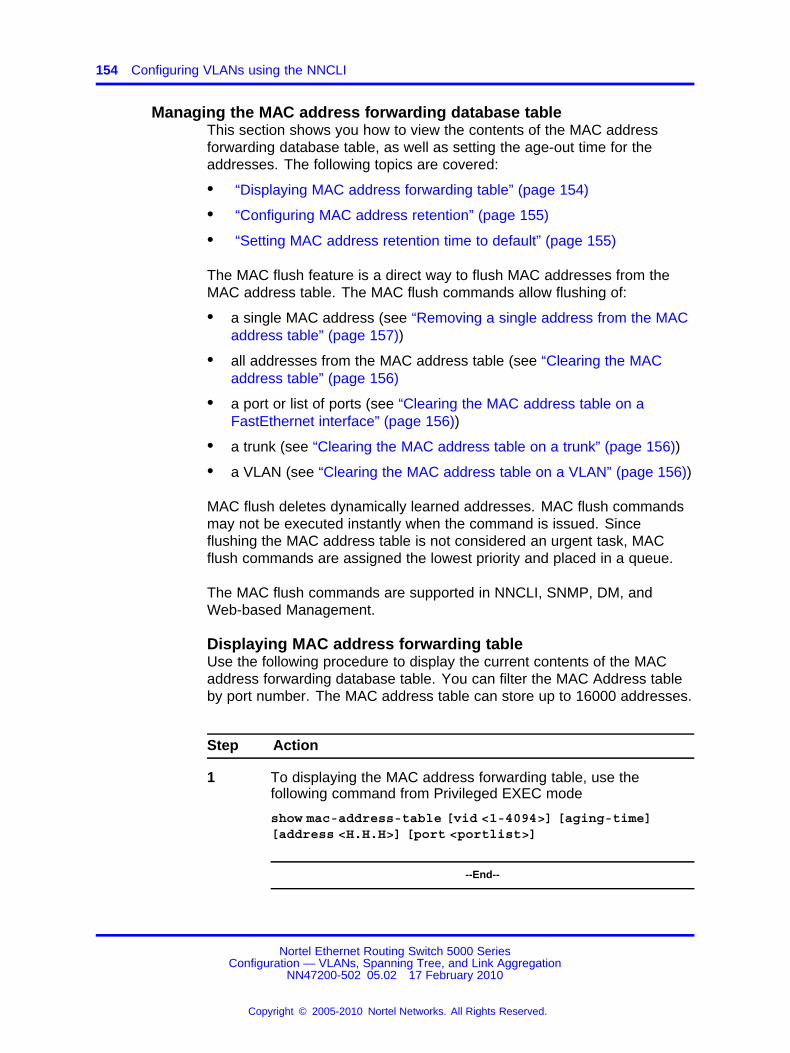
154 Configuring VLANs using the NNCLI
Managing the MAC address forwarding database tableThis section shows you how to view the contents of the MAC addressforwarding database table, as well as setting the age-out time for theaddresses. The following topics are covered:
• “Displaying MAC address forwarding table” (page 154)
• “Configuring MAC address retention” (page 155)
• “Setting MAC address retention time to default” (page 155)
The MAC flush feature is a direct way to flush MAC addresses from theMAC address table. The MAC flush commands allow flushing of:
• a single MAC address (see “Removing a single address from the MACaddress table” (page 157))
• all addresses from the MAC address table (see “Clearing the MACaddress table” (page 156)
• a port or list of ports (see “Clearing the MAC address table on aFastEthernet interface” (page 156))
• a trunk (see “Clearing the MAC address table on a trunk” (page 156))
• a VLAN (see “Clearing the MAC address table on a VLAN” (page 156))
MAC flush deletes dynamically learned addresses. MAC flush commandsmay not be executed instantly when the command is issued. Sinceflushing the MAC address table is not considered an urgent task, MACflush commands are assigned the lowest priority and placed in a queue.
The MAC flush commands are supported in NNCLI, SNMP, DM, andWeb-based Management.
Displaying MAC address forwarding tableUse the following procedure to display the current contents of the MACaddress forwarding database table. You can filter the MAC Address tableby port number. The MAC address table can store up to 16000 addresses.
Step Action
1 To displaying the MAC address forwarding table, use thefollowing command from Privileged EXEC mode
show mac-address-table [vid <1-4094>] [aging-time][address <H.H.H>] [port <portlist>]
--End--
Nortel Ethernet Routing Switch 5000 SeriesConfiguration — VLANs, Spanning Tree, and Link Aggregation
NN47200-502 05.02 17 February 2010
Copyright © 2005-2010 Nortel Networks. All Rights Reserved.
.

Creating and Managing VLANs using the NNCLI 155
Variable Value
vid <1-4094> Enter the number of the VLAN for which youwant to display the forwarding database.Default is to display the management VLAN’sdatabase.
aging-time Displays the time in seconds after which anunused entry is removed from the forwardingdatabase.
address <H.H.H> Displays a specific MAC address if it existsin the database. Enter the MAC address youwant displayed.
Configuring MAC address retentionUse the following procedure to set the time during which the switch retainsunseen MAC addresses.
Step Action
1 To configure unseen MAC address retention, use the followingcommand from Global Configuration mode.
mac-address-table aging-time <10-1 000 000>
--End--
Variable Value
vid <10-1 000 000> Enter the aging time in seconds that you wantfor MAC addresses before they expire.
Setting MAC address retention time to defaultUse the following procedure to set the retention time for unseen MACaddresses to 300 seconds.
Step Action
1 To set the MAC address retention time to default, use thefollowing command from Global Configuration mode.
default mac-address-table aging-time
--End--
Nortel Ethernet Routing Switch 5000 SeriesConfiguration — VLANs, Spanning Tree, and Link Aggregation
NN47200-502 05.02 17 February 2010
Copyright © 2005-2010 Nortel Networks. All Rights Reserved.
.

156 Configuring VLANs using the NNCLI
Clearing the MAC address tableUse the following procedure to clear the MAC address table.
Step Action
1 To flush the MAC address table, use the following commandfrom Privileged EXEC mode.
clear mac-address-table
--End--
Clearing the MAC address table on a VLANUse the following procedure to flush the MAC addresses for the specifiedVLAN.
Step Action
1 To flush the MAC address table for a specific VLAN, use thefollowing command from Privileged EXEC mode.
clear mac-address-table interface vlan <vlan #>
--End--
Clearing the MAC address table on a FastEthernet interfaceUse the following procedure to flush the MAC addresses for the specifiedports. This command does not flush the addresses learned on the trunk.
Step Action
1 TO clear the MAC address table on a FastEthernet interface, usethe following command from Privileged EXEC mode.
clear mac-address-table interface FastEthernet<port-list|ALL>
--End--
Clearing the MAC address table on a trunkUse the following procedure to flush the MAC addresses for the specifiedtrunk. This command flushes only addresses that are learned on the trunk.
Nortel Ethernet Routing Switch 5000 SeriesConfiguration — VLANs, Spanning Tree, and Link Aggregation
NN47200-502 05.02 17 February 2010
Copyright © 2005-2010 Nortel Networks. All Rights Reserved.
.

Creating and Managing VLANs using the NNCLI 157
Step Action
1 To clear the MAC address table on a trunk, use the followingcommand from Privileged EXEC mode.
clear mac-address-table interface mlt <trunk_number>
--End--
Removing a single address from the MAC address tableUse the following procedure to flush one MAC address from the MACaddress table.
Step Action
1 To flush a single MAC address, use the following command fromPrivileged EXEC mode.
clear mac-address-table address <H.H.H>
--End--
IP Directed BroadcastingIP directed broadcasting takes the incoming unicast Ethernet frame,determines that the destination address is the directed broadcast for oneof its interfaces, and then forwards the datagram onto the appropriatenetwork using a link-layer broadcast.
IP directed broadcasting in a VLAN forwards direct broadcast packets intwo ways:
• Through a connected VLAN subnet to another connected VLANsubnet.
• Through a remote VLAN subnet to the connected VLAN subnet.
By default, this feature is disabled.
The following NNCLI commands are used to work with IP directedbroadcasting:
• “Enabling IP directed broadcast” (page 157)
Enabling IP directed broadcastUse the following procedure to enable IP directed broadcast.
Nortel Ethernet Routing Switch 5000 SeriesConfiguration — VLANs, Spanning Tree, and Link Aggregation
NN47200-502 05.02 17 February 2010
Copyright © 2005-2010 Nortel Networks. All Rights Reserved.
.

158 Configuring VLANs using the NNCLI
Step Action
1 To enable IP directed broadcast, use the following commandfrom Global Configuration mode.
[no] ip directed-broadcast enable
Use the no form of this command to disable.
--End--
Nortel Ethernet Routing Switch 5000 SeriesConfiguration — VLANs, Spanning Tree, and Link Aggregation
NN47200-502 05.02 17 February 2010
Copyright © 2005-2010 Nortel Networks. All Rights Reserved.
.

159.
Configuring STP using the NNCLI
Setting the STP mode using the NNCLIUse the following procedure to set the STP operational mode to STPG(Nortel Multiple Spanning Tree Protocol), RSTP (802.1w Rapid SpanningTree Protocol), or MSTP (802.1s Multiple Spanning Tree Protocol).
Procedure steps
Step Action
1 To set the STP mode, use the following command from GlobalConfiguration mode.
spanning-tree op-mode {stpg | rstp | mstp}
--End--
Configuring STP BPDU Filtering using the NNCLIUse the following procedure to configure STP BPDU Filtering on a port.This command is available in all STP modes (STPG, RSTP, and MSTP).
Procedure steps
Step Action
1 To enable STP BPDU filtering, use the following command fromInterface Configuration mode.
[no] spanning-tree bpdu-filtering [port <portlist>][enable] [timeout <10-65535 | 0> ]
Use the no form of this command to disable.
2 To set the STP BPDU Filtering properties on a port to theirdefault values, use the following command from the InterfaceConfiguration command mode:
default spanning-tree bpdu-filtering [port <portlist>][enable] [timeout]
Nortel Ethernet Routing Switch 5000 SeriesConfiguration — VLANs, Spanning Tree, and Link Aggregation
NN47200-502 05.02 17 February 2010
Copyright © 2005-2010 Nortel Networks. All Rights Reserved.
.

160 Configuring STP using the NNCLI
3 To show the current status of the BPDU Filtering parameters,use the following command from the Privileged EXEC mode:
show spanning-tree bpdu-filtering [<interface-type>][port <portlist>]
--End--
Variable definitions
Variable Value
port <portlist> Specifies the ports affected by the command.
enable Enables STP BPDU Filtering on the specifiedports. The default value is disabled.
timeout <10-65535 | 0 > When BPDU filtering is enabled, this indicatesthe time (in seconds) during which the portremains disabled after it receives a BPDU. Theport timer is disabled if this value is set to 0.The default value is 120 seconds.
Creating and Managing STGs using the NNCLITo create and manage Spanning Tree Groups, you can refer to theCommand Line Interface commands listed in this section. Depending onthe type of Spanning Tree Group that you want to create or manage, thecommand mode needed to execute these commands can differ.
In the following commands, the omission of any parameters that specify aSpanning Tree Group results in the command operating against the defaultSpanning Tree Group (Spanning Tree Group 1).
To configure STGs using the NNCLI, refer to the following:
• “Configuring path cost calculation mode” (page 161)
• “Configuring STG port membership mode” (page 161)
• “Displaying STP configuration information” (page 161)
• “Creating a Spanning Tree Group” (page 162)
• “Deleting a Spanning Tree Group” (page 162)
• “Enabling a Spanning Tree Group” (page 163)
• “Disabling a Spanning Tree Group” (page 163)
• “Configuring STP values” (page 163)
• “Restoring default Spanning Tree values” (page 165)
Nortel Ethernet Routing Switch 5000 SeriesConfiguration — VLANs, Spanning Tree, and Link Aggregation
NN47200-502 05.02 17 February 2010
Copyright © 2005-2010 Nortel Networks. All Rights Reserved.
.

Creating and Managing STGs using the NNCLI 161
• “Adding a VLAN to a STG” (page 165)
• “Removing a VLAN from a STG” (page 166)
• “Configuring STP and MSTG participation” (page 166)
• “Resetting Spanning Tree values for ports to default” (page 167)
Configuring path cost calculation modeUse the following procedure to set the path cost calculation mode for allSpanning Tree Groups on the switch.
Procedure steps
Step Action
1 To configure path cost calculation mode, use the followingcommand from Privileged EXEC mode.
spanning-tree cost-calc-mode {dot1d | dot1t}
--End--
Configuring STG port membership modeUse the following procedure to set the STG port membership mode for allSpanning Tree Groups on the switch.
Procedure steps
Step Action
1 To configure STG port membership mode, use the followingcommand from Privileged EXEC mode.
spanning-tree port-mode {auto | normal}
--End--
Displaying STP configuration informationUse the following procedure to display spanning tree configurationinformation that is specific to either the Spanning Tree Group or to theport.
Nortel Ethernet Routing Switch 5000 SeriesConfiguration — VLANs, Spanning Tree, and Link Aggregation
NN47200-502 05.02 17 February 2010
Copyright © 2005-2010 Nortel Networks. All Rights Reserved.
.

162 Configuring STP using the NNCLI
Procedure steps
Step Action
1 To display STP configuration information, use the followingcommand from Privileged EXEC mode.
show spanning-tree [stp <1-8>] {config | port| port-mode| vlans}
--End--
Variable definitions
Variable Value
stp <1-8> Displays specified Spanning Tree Groupconfiguration; enter the number of the group tobe displayed.
config | port | port-mode |vlans
Displays spanning tree configuration for:• config--the specified (or default) Spanning
Tree Group
• port--the ports within the Spanning TreeGroup
• port-mode--the port mode
• vlans--the VLANs that are members of thespecified Spanning Tree Group
Creating a Spanning Tree GroupUse the following procedure to create a Spanning Tree Group.
Procedure steps
Step Action
1 To create a Spanning Tree Group, use the following commandfrom Global Configuration mode.
spanning-tree stp <1-8> create
--End--
Deleting a Spanning Tree GroupUse the following procedure to delete a Spanning Tree Group.
Nortel Ethernet Routing Switch 5000 SeriesConfiguration — VLANs, Spanning Tree, and Link Aggregation
NN47200-502 05.02 17 February 2010
Copyright © 2005-2010 Nortel Networks. All Rights Reserved.
.
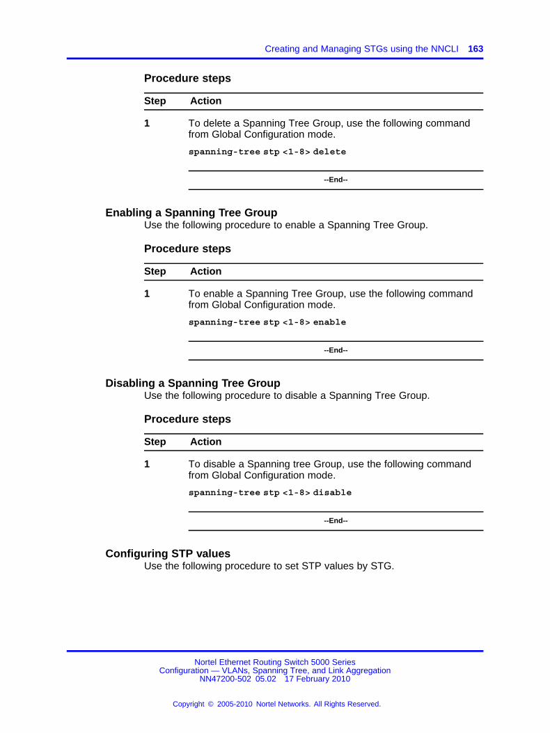
Creating and Managing STGs using the NNCLI 163
Procedure steps
Step Action
1 To delete a Spanning Tree Group, use the following commandfrom Global Configuration mode.
spanning-tree stp <1-8> delete
--End--
Enabling a Spanning Tree GroupUse the following procedure to enable a Spanning Tree Group.
Procedure steps
Step Action
1 To enable a Spanning Tree Group, use the following commandfrom Global Configuration mode.
spanning-tree stp <1-8> enable
--End--
Disabling a Spanning Tree GroupUse the following procedure to disable a Spanning Tree Group.
Procedure steps
Step Action
1 To disable a Spanning tree Group, use the following commandfrom Global Configuration mode.
spanning-tree stp <1-8> disable
--End--
Configuring STP valuesUse the following procedure to set STP values by STG.
Nortel Ethernet Routing Switch 5000 SeriesConfiguration — VLANs, Spanning Tree, and Link Aggregation
NN47200-502 05.02 17 February 2010
Copyright © 2005-2010 Nortel Networks. All Rights Reserved.
.

164 Configuring STP using the NNCLI
Procedure steps
Step Action
1 To configure STP values, use the following command fromGlobal Configuration mode.
spanning-tree [stp <1-8>] [forward-time <4-30>][hello-time <1-10>] [max-age <6-40>] [priority {0*0000| 0*1000| 0*2000 | 0*3000 | ... | 0*E000 | 0*F000}][tagged-bpdu {enable | disable}] [tagged-bpdu-vid<1-4094>] [multicast-address <H.H.H>] [add-vlan][remove-vlan]
--End--
Variable definitions
Variable Value
stp <1-8> Specifies the Spanning Tree Group; enter theSTG ID.
forward-time<4-30>
Enter the forward time of the STG in seconds;the range is 4 -- 30, and the default value is15.
hello-time<1-10>
Enter the hello time of the STG in seconds; therange is 1 --10, and the default value is 2.
max-age<6-40>
Enter the max-age of the STG in seconds; therange is 6 -- 40, and the default value is 20.
priority {0x000 | 0x1000| 0x2000 | 0x3000 | .... |0xE000 | 0xF000}
Sets the spanning tree priority (in Hex); if802.1T compliant, this value must be a multipleof 0x1000.
tagged-bpdu {enable | disable} Sets the BPDU as tagged or untagged. Thedefault value for Spanning Tree Group 1(default group) is untagged; the default for theother groups is tagged.
tagged-bpdu-vid <1-4094> Sets the VLAN ID (VID) for the tagged BPDU.The default value is 4001 -- 4008 for STG 1 --8, respectively.
multicast-address <H.H.H> Sets the spanning tree multicast address.
add-vlan Adds a VLAN to the Spanning Tree Group.
remove-vlan Removes a VLAN from the Spanning TreeGroup.
Nortel Ethernet Routing Switch 5000 SeriesConfiguration — VLANs, Spanning Tree, and Link Aggregation
NN47200-502 05.02 17 February 2010
Copyright © 2005-2010 Nortel Networks. All Rights Reserved.
.

Creating and Managing STGs using the NNCLI 165
Restoring default Spanning Tree valuesUse the following procedure to restore default spanning tree values forthe Spanning Tree Group.
Procedure steps
Step Action
1 To restore Spanning Tree values to default, use the followingcommand from Global Configuration mode.
default spanning-tree [stp <1-8>] [forward-time][hello-time] [max-age] [priority] [tagged-bpdu][multicast address]
--End--
Variable definitions
Variable Value
stp <1-8> Disables the Spanning Tree Group; enter theSTG ID.
forward-time Sets the forward time to the default value of 15seconds.
hello-time Sets the hello time to the default value of 2seconds.
max-age Sets the maximum age time to the defaultvalue of 20 seconds.
priority Sets spanning tree priority (in Hex); if 802.1Tcompliant, this value must be a multiple of0x1000.
tagged-bpdu Sets the tagging to the default value. Thedefault value for Spanning Tree Group 1(default group) is untagged; the default for theother groups is tagged.
multicast address Sets the spanning tree multicast MAC addressto the default.
Adding a VLAN to a STGUse the following procedure to add a VLAN to a specified Spanning TreeGroup.
Nortel Ethernet Routing Switch 5000 SeriesConfiguration — VLANs, Spanning Tree, and Link Aggregation
NN47200-502 05.02 17 February 2010
Copyright © 2005-2010 Nortel Networks. All Rights Reserved.
.

166 Configuring STP using the NNCLI
Procedure steps
Step Action
1 To add a VLAN to a STG, use the following command fromGlobal Configuration mode.
spanning-tree [stp <1-8>] add-vlan <1-4094>
--End--
Removing a VLAN from a STGUse the following procedure to remove a VLAN from a specified SpanningTree Group.
Procedure steps
Step Action
1 To remove a VLAN from a STG, use the following commandfrom Global Configuration mode.
spanning-tree [stp <1-8>] remove-vlan <1-4094>
--End--
Configuring STP and MSTG participationUse the following procedure to set the Spanning Tree Protocol (STP) andmultiple Spanning Tree Group (STG) participation for the ports within thespecified Spanning Tree Group.
Procedure steps
Step Action
1 To configure STP and MSTG participation, use the followingcommand from Interface Configuration mode.
[no] spanning-tree [port <portlist>] [stp <1-8>][learning {disable | normal | fast}] [cost <1-65535>][priority]
Use the no form of this command to disable.
--End--
Nortel Ethernet Routing Switch 5000 SeriesConfiguration — VLANs, Spanning Tree, and Link Aggregation
NN47200-502 05.02 17 February 2010
Copyright © 2005-2010 Nortel Networks. All Rights Reserved.
.

Creating and Managing STGs using the NNCLI 167
Variable definitions
Variable Value
port <portlist> Enables the spanning tree for the specifiedport or ports; enter port or ports you wantenabled for the spanning tree.
Note: If you omit this parameter, the systemuses the port number you specified when youissued the interface command to enter theInterface Configuration mode.
stp <1-8> Specifies the spanning tree group; enter theSTG ID.
learning{disable|normal|fast}
Specifies the STP learning mode:
• disable -- disables FastLearn mode
• normal -- changes to normal learning mode
• fast -- enables FastLearn mode
cost <1-65535> Enter the path cost of the spanning tree; rangeis 1 -- 65535.
priority Sets the spanning tree priority for a port asa hexadecimal value. If the Spanning TreeGroup is 802.1T compliant, this value must bea multiple of 0x10.
Resetting Spanning Tree values for ports to defaultUse the following procedure to set the spanning tree values for the portswithin the specified Spanning Tree Group to the factory default settings.
Procedure steps
Step Action
1 To reset Spanning Tree values to default, use the followingcommand from Interface Configuration mode.
default spanning-tree [port <portlist>] [stp <1-8>][learning] [cost] [priority]
--End--
Nortel Ethernet Routing Switch 5000 SeriesConfiguration — VLANs, Spanning Tree, and Link Aggregation
NN47200-502 05.02 17 February 2010
Copyright © 2005-2010 Nortel Networks. All Rights Reserved.
.

168 Configuring STP using the NNCLI
Variable definitions
Variable Value
port <portlist> Enables spanning tree for the specified port orports; enter port or ports to be set to factoryspanning tree default values.
Note: If this parameter is omitted, the systemuses the port number specified when theinterface command was used to enter InterfaceConfiguration mode.
stp <1-8> Specifies the Spanning Tree Group to set tofactory default values; enter the STG ID. Thiscommand places the port into the default STG.The default value for STG is 1.
learning Sets the spanning tree learning mode to thefactory default value.
The default value for learning is Normal mode.
cost Sets the path cost to the factory default value.
The default value for path cost depends on thetype of port.
priority Sets the priority to the factory default value.
The default value for the priority is 0x8000.
Managing RSTP using the NNCLIUse the following command to configure RSTP:
• “Configuring RSTP parameters” (page 168)
• “Configuring RSTP on a port” (page 169)
• “Displaying RSTP configuration” (page 170)
• “Displaying RSTP port configuration” (page 171)
Configuring RSTP parametersUse the following procedure to set the RSTP parameters which includeforward delay, hello time, maximum age time, default path cost version,bridge priority, transmit holdcount, and version for the bridge.
Nortel Ethernet Routing Switch 5000 SeriesConfiguration — VLANs, Spanning Tree, and Link Aggregation
NN47200-502 05.02 17 February 2010
Copyright © 2005-2010 Nortel Networks. All Rights Reserved.
.

Managing RSTP using the NNCLI 169
Procedure steps
Step Action
1 To configure RSTP parameters, use the following command fromGlobal Configuration mode.
spanning-tree rstp [ forward-time <4 - 30>][hello-time <1 - 10>] [max-age <6 - 40>][pathcost-type {bits16 | bits32}][priority {0000|1000|2000| ...| F000}][tx-holdcount <1 - 10>][version {stp-compatible | rstp}]
--End--
Variable definitions
Variable Value
forward-time<4- 30>
Sets the RSTP forward delay for the bridge in seconds;the default is 15.
hello-time<1- 10>
Sets the RSTP hello time delay for the bridge inseconds; the default is 2.
max-age<6 - 40>
Sets the RSTP maximum age time for the bridge inseconds; the default is 20.
pathcost-type{bits16 | bits32}
Sets the RSTP default path cost version; the default isbits32.
priority {0000 | 1000 |... | F000}
Sets the RSTP bridge priority (in hex); the default is8000.
tx-hold count Sets the RSTP Transmit Hold Count; the default is 3.
version{stp-compatible | rstp}
Sets the RSTP version; the default is rstp.
Configuring RSTP on a portUse the following procedure to set the RSTP parameters, which includepath cost, edge-port indicator, learning mode, point-to-point indicator,priority, and protocol migration indicator on the single or multiple port.
Procedure steps
Step Action
1 To configure RSTP on a port, use the following command fromInterface Configuration mode.
Nortel Ethernet Routing Switch 5000 SeriesConfiguration — VLANs, Spanning Tree, and Link Aggregation
NN47200-502 05.02 17 February 2010
Copyright © 2005-2010 Nortel Networks. All Rights Reserved.
.

170 Configuring STP using the NNCLI
spanning-tree rstp [port <portlist>] [cost <1 -200000000>][edge-port {false | true}][learning {disable | enable}][p2p {auto | force-false | force-true}][priority {00 | 10 | ... | F0}][protocol-migration {false | true}]
--End--
Variable definitions
Variable Value
port <portlist> Filter on list of ports.
cost <1 - 200000000> Sets the RSTP path cost on the single or multiple ports;the default is 200000.
edge-port {false | true} Indicates whether the single or multiple ports are assumedto be edge ports. This parameter sets the Admin value ofedge port status; the default is false.
learning {disable |enable}
Enables or disables RSTP on the single or multiple ports;the default is enable.
p2p {auto | force-false |force-true}
Indicates whether the single or multiple ports are to betreated as point-to-point links. This command sets theAdmin value of P2P Status; the default is force-true.
priority {00 | 10 |... |F0}
Sets the RSTP port priority on the single or multiple ports;the default is 80.
protocol-migration {false| true}
Forces the single or multiple port to transmit RSTPBPDUs when set to true, while operating in RSTP mode;the default is false.
Displaying RSTP configurationUse the following procedure to display the Rapid Spanning Tree Protocol(RSTP) related bridge-level configuration details.
Procedure steps
Step Action
1 To display RSTP configuration details, use the followingcommand from Privileged EXEC mode.
show spanning-tree rstp {config | status | statistics}
--End--
Nortel Ethernet Routing Switch 5000 SeriesConfiguration — VLANs, Spanning Tree, and Link Aggregation
NN47200-502 05.02 17 February 2010
Copyright © 2005-2010 Nortel Networks. All Rights Reserved.
.
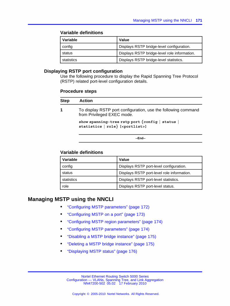
Managing MSTP using the NNCLI 171
Variable definitions
Variable Value
config Displays RSTP bridge-level configuration.
status Displays RSTP bridge-level role information.
statistics Displays RSTP bridge-level statistics.
Displaying RSTP port configurationUse the following procedure to display the Rapid Spanning Tree Protocol(RSTP) related port-level configuration details.
Procedure steps
Step Action
1 To display RSTP port configuration, use the following commandfrom Privileged EXEC mode.
show spanning-tree rstp port {config | status |statistics | role} [<portlist>]
--End--
Variable definitions
Variable Value
config Displays RSTP port-level configuration.
status Displays RSTP port-level role information.
statistics Displays RSTP port-level statistics.
role Displays RSTP port-level status.
Managing MSTP using the NNCLI• “Configuring MSTP parameters” (page 172)
• “Configuring MSTP on a port” (page 173)
• “Configuring MSTP region parameters” (page 174)
• “Configuring MSTP parameters” (page 174)
• “Disabling a MSTP bridge instance” (page 175)
• “Deleting a MSTP bridge instance” (page 175)
• “Displaying MSTP status” (page 176)
Nortel Ethernet Routing Switch 5000 SeriesConfiguration — VLANs, Spanning Tree, and Link Aggregation
NN47200-502 05.02 17 February 2010
Copyright © 2005-2010 Nortel Networks. All Rights Reserved.
.

172 Configuring STP using the NNCLI
• “Displaying MSTP Cist port information” (page 176)
• “Displaying MSTP MSTI settings” (page 177)
Configuring MSTP parametersUse the following procedure to set the MSTP parameters, which includemaximum hop count, maximum number of instances allowed, forwarddelay time, hello time, maximum age time, default path cost version,priority, transmit hold count, and version for the Cist Bridge.
Procedure steps
Step Action
1 To configure MSTP parameters, use the following commandfrom Global Configuration mode.
spanning-tree mstp [max-hop <600 - 4000>][forward-time <4 - 30>][max-age <6 - 40>][pathcost-type {bits16 | bits32}][priority {0000 | 1000 | 2000 | ... | F000}][tx-hold count <1 - 10>][version {stp-compatible | rstp| mstp}][add-vlan <1 - 4094>] [remove-vlan <1 - 4094>]
--End--
Variable definitions
Variable Value
max-hop<600 - 4000>
Sets the MSTP maximum hop count for the CISTbridge; the default is 2000.
forward-time<4 - 30>
Sets the MSTP forward delay for the CIST bridge inseconds; the default is 15.
max-age<6 - 40>
Sets the MSTP maximum age time for the CIST bridgein seconds; the default is 20.
pathcost-type{bits16 | bits32}
Sets the MSTP default path cost version; the defaultis bits32.
priority {0000 |1000|2000 ... | F000}
Sets the MSTP bridge priority for the CIST Bridge; thedefault is 8000.
tx-holdcount<1 - 10> Sets the MSTP Transmit Hold Count; the default is 3.
Nortel Ethernet Routing Switch 5000 SeriesConfiguration — VLANs, Spanning Tree, and Link Aggregation
NN47200-502 05.02 17 February 2010
Copyright © 2005-2010 Nortel Networks. All Rights Reserved.
.

Managing MSTP using the NNCLI 173
Variable Value
version{stp-compatible | rstp |mstp}
Sets the MSTP version for the Cist Bridge; the defaultis mstp.
add-vlan<1 - 4094>
Adds a VLAN to the CIST bridge.
remove-vlan<1 - 4094>
Removes the specified VLAN from the CIST bridge.
Configuring MSTP on a portUse the following procedure to set the MSTP parameters, which includepath cost, hello time, edge-port indicator, learning mode, point-to-pointindicator, priority, and protocol migration indicator on the single or multipleports for the Common Spanning Tree.
Procedure steps
Step Action
1 To configure MSTP on a port, use the following command fromInterface Configuration mode.
spanning-tree mstp [port <portlist>] [cost <1 -200000000>][edge-port {false | true}][hello-time <1 -10>][learning {disable | enable}][p2p {auto | force-false |force-true}][priority {00 | 10 | < | F0}][protocol-migration {false | true}]
--End--
Variable definitions
Variable Value
port <portlist> Enter a list or range of port numbers.
cost <1 - 200000000> Sets the MSTP path cost on the single or multipleports for the CIST; the default is 200000.
hello-time<1 - 10>
Sets the MSTP hello time on the single or multipleports for the CIST; the default is 2.
edge-port {false | true} Indicates whether the single or multiple ports areassumed to be edge ports. This parameter setsthe Admin value of edge port status; the default isfalse.
Nortel Ethernet Routing Switch 5000 SeriesConfiguration — VLANs, Spanning Tree, and Link Aggregation
NN47200-502 05.02 17 February 2010
Copyright © 2005-2010 Nortel Networks. All Rights Reserved.
.

174 Configuring STP using the NNCLI
Variable Value
learning {disable | enable} Enables or disables MSTP on the single or multipleports; the default is enable.
p2p {auto |force-false |force-true}
Indicates whether the single or multiple ports aretreated as point-to-point links. This commandsets the Admin value of P2P Status; the default isforce-true.
priority {00 | 10 |... | F0} Sets the MSTP port priority on the single ormultiple ports; the default is 80.
protocol-migration {false |true}
Forces the single or multiple ports to transmitMSTP BPDUs when set to true, while operating inMSTP mode; the default is false.
Configuring MSTP region parametersUse the following procedure to set the MSTP parameters, which includeconfig ID selector, region name, and region version.
Procedure steps
Step Action
1 To configure MSTP region parameters, use the followingcommand from Global Configuration mode.
spanning-tree mstp region [config-id-sel <0 - 255>][region-name <1 - 32 chars>][region-version <0 - 65535>]
--End--
Variable definitions
Variable Value
[config-id-sel<0 - 255>]
Sets the MSTP config ID selector; the default is 0.
[region-name<1 - 32 chars>]
Sets the MSTP region name; the default is the bridgeMAC address.
[region-version<0 - 65535>]
Sets the MSTP region version; the default is 0.
Configuring MSTP parametersUse the following procedure to set the MSTP parameters, which includeforward delay time, hello-time, maximum hop count, priority, and VLANmapping for the bridge instance.
Nortel Ethernet Routing Switch 5000 SeriesConfiguration — VLANs, Spanning Tree, and Link Aggregation
NN47200-502 05.02 17 February 2010
Copyright © 2005-2010 Nortel Networks. All Rights Reserved.
.

Managing MSTP using the NNCLI 175
Procedure steps
Step Action
1 To configure MSTP parameters, use the following commandfrom Global Configuration mode.
spanning-tree mstp msti <1 - 7>[priority{0000|1000|...|F000}][add-vlan <vid>][remove-vlan <vid>][enable]
--End--
Variable definitions
Variable Value
<1 - 7> Filter on MSTP instance.
priority {0000 |1000 |... | F000}
Sets the MSTP priority for the bridge instance; thedefault is 8000.
add-vlan <1 - 4094> Maps the specified Vlan and MSTP bridgeinstance.
remove-vlan<1 - 4094>
Unmaps the specified Vlan and MSTP bridgeinstance.
enable Enables the MSTP bridge instances.
Disabling a MSTP bridge instanceUse the following procedure to disable a MSTP bridge instance.
Procedure steps
Step Action
1 To disable a MSTP bridge instance, use the following commandfrom Global Configuration mode.
no spanning-tree mstp msti <1 - 7> enable
--End--
Deleting a MSTP bridge instanceUse the following procedure to delete a MSTP bridge-instance.
Nortel Ethernet Routing Switch 5000 SeriesConfiguration — VLANs, Spanning Tree, and Link Aggregation
NN47200-502 05.02 17 February 2010
Copyright © 2005-2010 Nortel Networks. All Rights Reserved.
.

176 Configuring STP using the NNCLI
Procedure steps
Step Action
1 To delete a MSTP bridge instance, use the following commandfrom Global Configuration mode.
no spanning-tree mstp msti <1 - 7>
--End--
Displaying MSTP statusUse the following procedure to display Multi Spanning Tree Protocol(MSTP) related status information known by the selected bridge.
Procedure steps
Step Action
1 To display MSTP status, use the following command fromPrivileged EXEC mode.
show spanning-tree mstp {config | status | statistics}
--End--
Variable definitions
Variable Value
config Displays the MSTP-related bridge-level VLANand region information.
status Displays the MSTP-related bridge-level statusinformation known by the selected bridge.
statistics Displays the MSTP-related bridge-levelstatistics.
Displaying MSTP Cist port informationUse the following procedure to display Multi Spanning Tree Protocol(MSTP) Cist Port information maintained by every port of the CommonSpanning Tree.
Nortel Ethernet Routing Switch 5000 SeriesConfiguration — VLANs, Spanning Tree, and Link Aggregation
NN47200-502 05.02 17 February 2010
Copyright © 2005-2010 Nortel Networks. All Rights Reserved.
.

Managing MSTP using the NNCLI 177
Procedure steps
Step Action
1 To display MSTP Cist port information, use the followingcommand from Privileged EXEC mode.
show spanning-tree mstp port {config | role | statistics} [<portlist>]
--End--
Variable definitions
Variable Value
<portlist> Enter a list or range of port numbers.
config Displays the MSTP CIST port informationmaintained by every port of the CommonSpanning Tree.
role Displays MSTP CIST related port roleinformation maintained by every port.
statistics Displays the MSTP CIST Port statisticsmaintained by every port.
Displaying MSTP MSTI settingsUse the following procedure to display MSTP MSTI settings.
Procedure steps
Step Action
1 To display MSTP MSTI settings, use the following commandfrom Global Configuration mode.
show spanning-tree mstp msti [config] [statistics] [port{config | role | statistics}] <1 - 7>
--End--
Variable definitions
Variable Value
config Displays the MSTP instance-specific configurationand the VLAN mapping port.
statistics Displays MSTP instance-specific statistics.
Nortel Ethernet Routing Switch 5000 SeriesConfiguration — VLANs, Spanning Tree, and Link Aggregation
NN47200-502 05.02 17 February 2010
Copyright © 2005-2010 Nortel Networks. All Rights Reserved.
.

178 Configuring STP using the NNCLI
Variable Value
port {config | role |statistics}
Displays MSTP instance-specific port information:• config: displays MSTI port configuration
• role: displays MSTI port role information
• statistics: displays MSTI port statistics
<1 - 7> Specifies the MSTI instance for which to displaythe statistics.
Nortel Ethernet Routing Switch 5000 SeriesConfiguration — VLANs, Spanning Tree, and Link Aggregation
NN47200-502 05.02 17 February 2010
Copyright © 2005-2010 Nortel Networks. All Rights Reserved.
.

179.
Configuring MLT using the NNCLIThe Command Line Interface commands detailed in this section allow forthe creation and management of Multi-Link trunks. Depending on the typeof Multi-Link trunk being created or managed, the command mode neededto execute these commands can differ.
Displaying MLT configuration and utilizationUse the following procedure to display Multi-Link Trunking (MLT)configuration and utilization.
Procedure steps
Step Action
1 To display MLT configuration and utilization, use the followingcommand from Privileged EXEC mode.
show mlt [utilization <1-32>]
--End--
Configuring a Multi-Link trunkUse the following procedure to configure a Multi-Link trunk (MLT).
Procedure steps
Step Action
1 To configure a Multi-Link trunk, use the following command fromGlobal Configuration mode.
mlt <id> [name <trunkname>] [enable | disable] [member<portlist>] [learning {disable | fast | normal}] [bpdu{all-ports | single-port}] loadbalance {basic | advance}
--End--
Nortel Ethernet Routing Switch 5000 SeriesConfiguration — VLANs, Spanning Tree, and Link Aggregation
NN47200-502 05.02 17 February 2010
Copyright © 2005-2010 Nortel Networks. All Rights Reserved.
.

180 Configuring MLT using the NNCLI
Variable definitions
Variable Value
id Enter the trunk ID; the range is 1 to 32.
name <trunkname> Specifies a text name for the trunk; enter up to16 alphanumeric characters.
enable | disable Enables or disables the trunk.
member <portlist> Enter the ports that are members of the trunk.
learning <disable | fast |normal>
Sets STP learning mode.
bpdu {all-ports | single-port} Sets trunk to send and receive BPDUs oneither all ports or a single port.
loadbalance {basic | advance} Sets the MLT load-balancing mode:- basic: MAC-based load-balancing- advance: IP-based load-balancing
Disabling a MLTUse the following procedure to disable a Multi-Link trunk (MLT), clearingall the port members.
Procedure steps
Step Action
1 To disable a MLT, use the following command from GlobalConfiguration mode.
no mlt [<id>]
--End--
Displaying MLT propertiesUse the following procedure to display the properties of Multi-Link trunks(MLT) participating in Spanning Tree Groups (STG).
Procedure steps
Step Action
1 To display MLT properties, use the following command fromGlobal Configuration mode.
Nortel Ethernet Routing Switch 5000 SeriesConfiguration — VLANs, Spanning Tree, and Link Aggregation
NN47200-502 05.02 17 February 2010
Copyright © 2005-2010 Nortel Networks. All Rights Reserved.
.

Configuring SMLT using the NNCLI 181
show mlt spanning-tree <1-32>
--End--
Configuring STP participation for MLTsUse the following procedure to set Spanning Tree Protocol (STP)participation for Multi-Link trunks (MLT).
Procedure steps
Step Action
1 To configure STP participation for MLTs, use the followingcommand from Global Configuration mode.
mlt spanning-tree <1-32> [stp <1-8, ALL>] [learning{disable | normal | fast}]
--End--
Variable definitions
Variable Value
<1 - 32> Specifies the ID of the MLT to associate withthe STG.
stp <1 - 8> Specifies the spanning tree group.
learning {disable | normal |fast}
Specifies the STP learning mode:
• disable -- disables learning
• normal -- sets the learning mode to normal
• fast -- sets the learning mode to fast
Configuring SMLT using the NNCLITo configure SMLT using the NNCLI, refer to the following:
• “Setting command mode to MLT Interface mode” (page 182)
• “Creating a SMLT” (page 182)
• “Creating a IST” (page 183)
• “Creating a SLT on a port” (page 184)
• “Disabling SMLT” (page 184)
• “DIsabling IST” (page 184)
Nortel Ethernet Routing Switch 5000 SeriesConfiguration — VLANs, Spanning Tree, and Link Aggregation
NN47200-502 05.02 17 February 2010
Copyright © 2005-2010 Nortel Networks. All Rights Reserved.
.

182 Configuring MLT using the NNCLI
• “Disabling a SLT on a port” (page 185)
• “Resetting SMLT to default” (page 185)
• “Resetting a IST to default” (page 186)
• “Resetting a SMLT to default” (page 186)
• “Displaying IST parameters” (page 186)
• “Displaying IST statistics” (page 187)
• “Displaying SLT and SMLT configurations” (page 187)
Note: To configure SMLT on the 5000 Series switch, an AdvancedLicense must be purchased that allows this feature to be used.
Setting command mode to MLT Interface mode
ATTENTIONFor SMLT to function properly, you must manually disable STP on all SMLT,IST, and SLT ports in all spanning tree groups or instances to which the portsbelong. You must also disable STP on all edge switch MLT ports that areconnected to the SMLT or SLT.
Use the following procedure to set the NNCLI command mode to MLTInterface mode from which you can configure SMLTs and ISTs.
Note: You create SLTs from the config-if command mode. For details,see “Creating a SLT on a port” (page 184).
Procedure steps
Step Action
1 To set the command mode, use the following command fromGlobal Configuration mode.
interface mlt [<1-32>]
--End--
Creating a SMLT
ATTENTIONFor SMLT to function properly, you must manually disable STP on all SMLT,IST, and SLT ports in all spanning tree groups or instances to which the portsbelong. You must also disable STP on all edge switch MLT ports that areconnected to the SMLT or SLT.
Use the following procedure to create a SMLT from an existing MLT.
Nortel Ethernet Routing Switch 5000 SeriesConfiguration — VLANs, Spanning Tree, and Link Aggregation
NN47200-502 05.02 17 February 2010
Copyright © 2005-2010 Nortel Networks. All Rights Reserved.
.

Configuring SMLT using the NNCLI 183
Procedure steps
Step Action
1 To create a SMLT, use the following command from InterfaceConfiguration mode.
smlt <1-32>
--End--
Note: Before you can create an SMLT, you must first create and enablean MLT (see “Configuring a Multi-Link trunk” (page 179)).
Creating a IST
ATTENTIONFor SMLT to function properly, you must manually disable STP on all SMLT,IST, and SLT ports in all spanning tree groups or instances to which the portsbelong. You must also disable STP on all edge switch MLT ports that areconnected to the SMLT or SLT.
Use the following procedure to create a IST from an existing MLT.
Procedure steps
Step Action
1 To create a IST, use the following command from MLT InterfaceConfiguration mode.
ist [enable] [peer-ip <A.B.C.D>] [vlan <1-4096>]
The peer IP address is the IP address of the IST VLAN on thepeer aggregation switch. A VLAN created on the redundantaggregation switch must also be created on the secondaggregation switch. The IST treats the two switches as a singleswitch. To allow the two switches to communicate, you mustassign an IP address to both VLANs.
--End--
Variable definitions
Variable Value
enable Enables the IST on the MLT specified by theinterface mlt command.
vlan <1-4096> Specifies a VLAN ID for the IST.
peer-ip <A.B.C.D> Specifies the peer IP address for the IST.
Nortel Ethernet Routing Switch 5000 SeriesConfiguration — VLANs, Spanning Tree, and Link Aggregation
NN47200-502 05.02 17 February 2010
Copyright © 2005-2010 Nortel Networks. All Rights Reserved.
.

184 Configuring MLT using the NNCLI
Creating a SLT on a port
ATTENTIONFor SMLT to function properly, you must manually disable STP on all SMLT,IST, and SLT ports in all spanning tree groups or instances to which the portsbelong. You must also disable STP on all edge switch MLT ports that areconnected to the SMLT or SLT.
Use the following procedure to create a SLT on a port.
Procedure steps
Step Action
1 To create a SLT on a port, use the following command fromInterface Configuration mode.
smlt [port <portlist>] <1-512>
--End--
Variable definitions
Variable Value
port <portlist> Specifies the port to configure as an SLT.
<1-512> Specifies the ID for the SLT.
Disabling SMLTUse the following procedure to disable a SMLT.
Procedure steps
Step Action
1 To disable a SMLT, use the following command from InterfaceConfiguration mode.
no smlt <1-32>
--End--
DIsabling ISTUse the following procedure to disable a IST and clear the IST settings.
Nortel Ethernet Routing Switch 5000 SeriesConfiguration — VLANs, Spanning Tree, and Link Aggregation
NN47200-502 05.02 17 February 2010
Copyright © 2005-2010 Nortel Networks. All Rights Reserved.
.

Configuring SMLT using the NNCLI 185
Procedure steps
Step Action
1 To disable a IST, use the following command from InterfaceConfiguration mode.
no ist [enable] [peer-ip]
--End--
Variable definitions
Variable Value
enable Disables the IST on the MLT specified by theinterface mlt command.
vlan <1-4096> Clears the VLAN ID from the IST.
peer-ip <A.B.C.D> Clears the peer IP address from the IST.
Disabling a SLT on a portUse the following procedure to disable a SLT on a port.
Procedure steps
Step Action
1 To disable a SLT on a port, use the following command fromInterface Configuration mode.
no smlt [port <portlist>]
--End--
Resetting SMLT to defaultUse the following procedure to reset a SMLT to default.
Procedure steps
Step Action
1 To reset a SMLT to default, use the following command fromInterface Configuration mode.
default smlt <1-32>
--End--
Nortel Ethernet Routing Switch 5000 SeriesConfiguration — VLANs, Spanning Tree, and Link Aggregation
NN47200-502 05.02 17 February 2010
Copyright © 2005-2010 Nortel Networks. All Rights Reserved.
.

186 Configuring MLT using the NNCLI
Resetting a IST to defaultUse the following procedure to reset a IST to default settings.
Procedure steps
Step Action
1 To reset a IST to default settings, use the following commandfrom MLT Interface Configuration mode.
default ist [enable] [peer-ip]
--End--
Variable definitions
Variable Value
enable Disables the IST on the MLT specified by the interface mltcommand.
peer-ip <A.B.C.D> Clears the peer IP address from the IST.
Resetting a SMLT to defaultUse the following procedure to reset SLT settings on a port to default.
Procedure steps
Step Action
1 To reset a SMLT to default, use the following command fromInterface Configuration mode.
default smlt [port <portlist>] <1-512>
--End--
Displaying IST parametersUse the following procedure to display the IST parameters on the switch.
Procedure steps
Step Action
1 To display IST parameters, use the following command fromPrivileged EXEC mode.
Nortel Ethernet Routing Switch 5000 SeriesConfiguration — VLANs, Spanning Tree, and Link Aggregation
NN47200-502 05.02 17 February 2010
Copyright © 2005-2010 Nortel Networks. All Rights Reserved.
.

Configuring SLPP using the NNCLI 187
show ist
--End--
Displaying IST statisticsUse the following procedure to display IST statistics on the switch.
Procedure steps
Step Action
1 To display IST statistics, use the following command fromPrivileged EXEC mode.
show ist stat
--End--
Displaying SLT and SMLT configurationsUse the following procedure to display SMLT and SLT configurations onthe switch.
Procedure steps
Step Action
1 To display SLT and SMLT configurations, use the followingcommand from Interface Configuration mode.
show smlt [<interface-type>]
--End--
Variable definitions
Variable Value
<interface-type> Interface types are• mlt: Displays only the MLT-based SMLTs
mlt id <1-32>
• fastethernet: Displays only the SLTsslt-id <1-512>
Configuring SLPP using the NNCLIThis section provides procedures used to configure Simple LoopPrevention Protocol (SLPP) using the NNCLI.
Nortel Ethernet Routing Switch 5000 SeriesConfiguration — VLANs, Spanning Tree, and Link Aggregation
NN47200-502 05.02 17 February 2010
Copyright © 2005-2010 Nortel Networks. All Rights Reserved.
.

188 Configuring MLT using the NNCLI
Configuring SLPP transmitting listThis procedures provides the steps necessary to add a VLAN to the SLPPtransmitting list.
Procedure steps
Step Action
1 To add a VLAN to the SLPP transmitting list, use the followingcommand from Global Configuration mode:
[no] slpp vid <1-4095>
Use the no form of this command to remove a VLAN from thelist.
--End--
Enabling SLPPThis procedure describes the steps necessary to globally enable SLPP.
Procedure steps
Step Action
1 To globally enable SLPP, use the following command fromGlobal Configuration mode:
[no] slpp enable
Use the no form of this command to disable SLPP.
--End--
Configuring SLPP PDU transmit intervalThis procedure describes the steps necessary to configure the SLPP PDUtransmit interval in milliseconds. The default setting is 500 ms.
Procedure steps
Step Action
1 To configure the SLPP PDU transmit interval, use the followingcommand from Global Configuration mode:
slpp tx-interval <500-5000>
--End--
Nortel Ethernet Routing Switch 5000 SeriesConfiguration — VLANs, Spanning Tree, and Link Aggregation
NN47200-502 05.02 17 February 2010
Copyright © 2005-2010 Nortel Networks. All Rights Reserved.
.
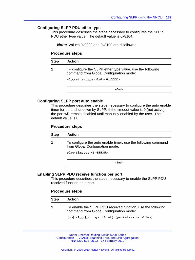
Configuring SLPP using the NNCLI 189
Configuring SLPP PDU ether typeThis procedure describes the steps necessary to configures the SLPPPDU ether type value. The default value is 0x8104.
Note: Values 0x0000 and 0x8100 are disallowed.
Procedure steps
Step Action
1 To configure the SLPP ether type value, use the followingcommand from Global Configuration mode:
slpp ethertype <0x0 - 0xffff>
--End--
Configuring SLPP port auto enableThis procedure describes the steps necessary to configure the auto enabletimer for ports shut down by SLPP. If the timeout value is 0 (not active),the port will remain disabled until manually enabled by the user. Thedefault value is 0.
Procedure steps
Step Action
1 To configure the auto enable timer, use the following commandfrom Global Configuration mode:
slpp timeout <1-65535>
--End--
Enabling SLPP PDU receive function per portThis procedure describes the steps necessary to enable the SLPP PDUreceived function on a port.
Procedure steps
Step Action
1 To enable the SLPP PDU received function, use the followingcommand from Global Configuration mode:
[no] slpp [port-portList] [packet-rx <enable>]
Nortel Ethernet Routing Switch 5000 SeriesConfiguration — VLANs, Spanning Tree, and Link Aggregation
NN47200-502 05.02 17 February 2010
Copyright © 2005-2010 Nortel Networks. All Rights Reserved.
.

190 Configuring MLT using the NNCLI
Use the no form of this command to disable the function.
--End--
Configuring the SLPP PDU receipt thresholdThis procedure describes the steps necessary to configure the number ofSLPP PDUs, in the range 1 to 500, that must be received prior to shuttingdown a port as a result of looping. The default threshold is 5.
Procedure steps
Step Action
1 To configure the SLPP PDU receipt threshold, use the followingcommand from Global Configuration mode:
[no] slpp [port-portList] [1-500 <enable>]
Use the no form of this command to reset to default (1).
--End--
Troubleshooting IST problemsThis section provides the steps used to troubleshooting IST problems andsingle-user problems.
Procedure steps
Step Action
1 Ensure that Global IP Routing is enabled.
2 Ensure that peers can ping each other.
3 Enter the show ist stat command to display the IST messagecount.
The hello count should increment.
4 Enter the show mlt command to display all the MLTs in theswitch and their properties, including running type, members,and status. Check the SMLT/SLT numbering: switchesconnected by SMLT must have the same SMLT IDs.
5 Ensure that the IST is up and running by using the show istcommand.
6 If the IST is not running, ensure that:
a The correct VLAN ID exists on both sides of the IST
Nortel Ethernet Routing Switch 5000 SeriesConfiguration — VLANs, Spanning Tree, and Link Aggregation
NN47200-502 05.02 17 February 2010
Copyright © 2005-2010 Nortel Networks. All Rights Reserved.
.

Troubleshooting IST problems 191
b The IST configuration contains the correct local and peer IPaddresses
7 If IST is running, check whether the SMLT port is operating byusing the show smlt command.
a If the current type is SMLT, the status is correct.
b If the current type is NORMAL, the link is running in a normal(single) mode and not in SMLT mode. The reasons for thiscan be as follows:
• The remote SMLT link is not operational.
• The ID is not configured on the other switch. To determinethis, check to see whether the SMLT IDs match.
• The IST is not up and running.
--End--
Nortel Ethernet Routing Switch 5000 SeriesConfiguration — VLANs, Spanning Tree, and Link Aggregation
NN47200-502 05.02 17 February 2010
Copyright © 2005-2010 Nortel Networks. All Rights Reserved.
.
192 Configuring MLT using the NNCLI
Nortel Ethernet Routing Switch 5000 SeriesConfiguration — VLANs, Spanning Tree, and Link Aggregation
NN47200-502 05.02 17 February 2010
Copyright © 2005-2010 Nortel Networks. All Rights Reserved.
.

193.
Configuring LACP and VLACP usingthe NNCLI
This section contains information on the following topics:
• “Configuring Link Aggregation using the NNCLI” (page 193)
• “Configuring VLACP using the NNCLI” (page 200)
Configuring Link Aggregation using the NNCLIThis section describes the commands necessary to configure and manageLink Aggregation using the Command Line Interface (NNCLI).
To configure Link Aggregation using the NNCLI, refer to the following:
• “Displaying LACP system settings” (page 194)
• “Displaying LACP per port configuration” (page 194)
• “Displaying LACP port mode” (page 194)
• “Displaying LACP port statistics” (page 195)
• “Clearing LACP port statistics” (page 195)
• “Displaying LACP port debug information” (page 195)
• “Displaying LACP aggregators” (page 196)
• “Configuring LACP system priority” (page 196)
• “Enabling LACP port aggregation mode” (page 196)
• “Configuring the LACP administrative key” (page 197)
• “Configuring LACP operating mode” (page 197)
• “Configuring per port LACP priority” (page 198)
• “Configuring LACP periodic transmission timeout interval” (page 199)
• “Configuring LACP port mode” (page 199)
Nortel Ethernet Routing Switch 5000 SeriesConfiguration — VLANs, Spanning Tree, and Link Aggregation
NN47200-502 05.02 17 February 2010
Copyright © 2005-2010 Nortel Networks. All Rights Reserved.
.

194 Configuring LACP and VLACP using the NNCLI
Displaying LACP system settingsUse the following procedure to display system-wide LACP settings.
Procedure steps
Step Action
1 To display system settings, use the following command fromPrivileged EXEC mode.
show lacp system
--End--
Displaying LACP per port configurationUse the following procedure to display information on the per-port LACPconfiguration. Select ports either by port number or by aggregator value.
Procedure steps
Step Action
1 To display per port configuration, use the following commandfrom Privileged EXEC mode.
show lacp port [<portList> | aggr <1-65535>]
--End--
Variable definitions
Variable Value
<portList>Enter the specific ports for which to display LACPinformation.
aggr <1-65535>Enter the aggregator value to display ports that aremembers of it.
Displaying LACP port modeUse the following procedure to display the current port mode (default oradvanced).
Procedure steps
Step Action
1 To display the port mode, use the following command fromPrivileged EXEC mode.
Nortel Ethernet Routing Switch 5000 SeriesConfiguration — VLANs, Spanning Tree, and Link Aggregation
NN47200-502 05.02 17 February 2010
Copyright © 2005-2010 Nortel Networks. All Rights Reserved.
.

Configuring Link Aggregation using the NNCLI 195
show lacp port-mode
--End--
Displaying LACP port statisticsUse the following procedure to displayLACP port statistics. Select portseither by port number or by aggregator value.
Procedure steps
Step Action
1 To display port statistics, use the following command fromPrivileged EXEC mode.
show lacp stats [<portList> | aggr <1-65535>]
--End--
Variable definitions
Variable Value
<portList>Enter the specific ports for which to display LACPinformation.
aggr <1-65535>Enter the aggregator value to display ports that aremembers of it.
Clearing LACP port statisticsUse the following procedure to clear existing LACP port statistics.
Procedure steps
Step Action
1 To clear statistics, use the following command from InterfaceConfiguration mode.
lacp clear-stats <portList>
--End--
Displaying LACP port debug informationUse the following procedure to display port debug information.
Nortel Ethernet Routing Switch 5000 SeriesConfiguration — VLANs, Spanning Tree, and Link Aggregation
NN47200-502 05.02 17 February 2010
Copyright © 2005-2010 Nortel Networks. All Rights Reserved.
.

196 Configuring LACP and VLACP using the NNCLI
Procedure steps
Step Action
1 To display port debug information, use the following commandfrom Privileged EXEC mode.
show lacp debug member [<portList>]
--End--
Displaying LACP aggregatorsUse the following procedure to display LACP aggregators or LACP trunks.
Procedure steps
Step Action
1 To display aggregators, use the following command fromPrivileged EXEC mode.
show lacp aggr <1-65535>
--End--
Configuring LACP system priorityUse the following procedure to configure the LACP system priority. It isused to set the system-wide LACP priority. The factory default priorityvalue is 32768.
Procedure steps
Step Action
1 To configure system priority, use the following command fromGlobal Configuration mode.
lacp system-priority <0-65535>
--End--
Enabling LACP port aggregation modeUse the following procedure to enable the port aggregation mode.
Nortel Ethernet Routing Switch 5000 SeriesConfiguration — VLANs, Spanning Tree, and Link Aggregation
NN47200-502 05.02 17 February 2010
Copyright © 2005-2010 Nortel Networks. All Rights Reserved.
.

Configuring Link Aggregation using the NNCLI 197
Procedure steps
Step Action
1 To enable the port aggregation mode, use the followingcommand from Interface Configuration mode.
[no] lacp aggregation [port <portList>] enable
Use the no form of the command to disable.
--End--
Configuring the LACP administrative keyUse the following procedure to configure the administrative LACP key for aset of ports.
Procedure steps
Step Action
1 To set the administrative key, use the following command fromInterface Configuration mode.
lacp key [port <portList>] <1-4095>
--End--
Variable definitions
Variable Value
port <portList> The ports to configure the LACP key for.
<1-4095> The LACP key to use.
Configuring LACP operating modeUse the following procedure to configure the LACP mode of operationsfor a set of ports.
Procedure steps
Step Action
1 To configure the operating mode, use the following commandfrom Interface Configuration mode.
Nortel Ethernet Routing Switch 5000 SeriesConfiguration — VLANs, Spanning Tree, and Link Aggregation
NN47200-502 05.02 17 February 2010
Copyright © 2005-2010 Nortel Networks. All Rights Reserved.
.

198 Configuring LACP and VLACP using the NNCLI
lacp mode [port <portList>] {active | passive | off}
--End--
Variable definitions
Variable Value
port <portList> The ports for which the LACP mode is to be set.
{active | passive | off} The type of LACP mode to set for the port. The LACPmodes are:• active -- The port will participate as an active
Link Aggregation port. Ports in active mode sendLACPDUs periodically to the other end to negotiatefor link aggregation.
• passive -- The port will participate as a passiveLink Aggregation port. Ports in passive mode sendLACPDUs only when the configuration is changedor when its link partner communicates first.
• off -- The port does not participate in LinkAggregation.
LACP requires at least one end of each link to be inactive mode.
Configuring per port LACP priorityUse the following procedure to configure the per-port LACP priority for aset of ports.
Procedure steps
Step Action
1 To configure priority, use the following command from InterfaceConfiguration mode.
lacp priority [port <portList>] <0-65535>
--End--
Variable definitions
Variable Value
port <portList> The ports for which to configure LACP priority.
<0-65535> The priority value to assign.
Nortel Ethernet Routing Switch 5000 SeriesConfiguration — VLANs, Spanning Tree, and Link Aggregation
NN47200-502 05.02 17 February 2010
Copyright © 2005-2010 Nortel Networks. All Rights Reserved.
.

Configuring Link Aggregation using the NNCLI 199
Configuring LACP periodic transmission timeout intervalUse the following procedure to configure the LACP periodic transmissiontimeout interval for a set of ports.
Procedure steps
Step Action
1 To configure the interval, use the following command fromInterface Configuration mode.
lacp timeout-time [port <portList>] {long | short}
--End--
Variable definitions
Variable Value
port <portList> The ports for which to configure the timeout interval.
{long | short} Specify the long or short timeout interval.
Configuring LACP port modeUse the following procedure to configure the LACP port mode on theswitch.
Procedure steps
Step Action
1 To configure the port mode, use the following command fromGlobal Configuration mode.
lacp port-mode {default | advance}
--End--
Variable definitions
Variable Value
default Default LACP port mode.
advance Advanced LACP port mode.
Nortel Ethernet Routing Switch 5000 SeriesConfiguration — VLANs, Spanning Tree, and Link Aggregation
NN47200-502 05.02 17 February 2010
Copyright © 2005-2010 Nortel Networks. All Rights Reserved.
.

200 Configuring LACP and VLACP using the NNCLI
Configuring VLACP using the NNCLITo configure VLACP using the NNCLI, refer to the following commands:
Note: When you set VLACP parameters for a trunk port, the settingsare applied to all trunk members.
• “Enabling VLACP globally” (page 200)
• “Configuring VLACP multicast MAC address” (page 200)
• “Configuring VLACP port parameters” (page 201)
• “Displaying VLACP status” (page 203)
• “Displaying VLACP port configuration” (page 204)
Enabling VLACP globallyUse the following procedure to globally enable VLACP for the device.
Procedure steps
Step Action
1 To enable VLACP, use the following command from GlobalConfiguration mode.
[no] vlacp enable
Use the no form of this command to disable.
--End--
Configuring VLACP multicast MAC addressUse the following procedure to set the multicast MAC address used bythe device for VLACPDUs.
Procedure steps
Step Action
1 To configure the multicast MAC address, use the followingcommand from Global Configuration mode.
[no] vlacp macaddress <macaddress>
Use the no form of this command to delete the address.
--End--
Nortel Ethernet Routing Switch 5000 SeriesConfiguration — VLANs, Spanning Tree, and Link Aggregation
NN47200-502 05.02 17 February 2010
Copyright © 2005-2010 Nortel Networks. All Rights Reserved.
.

Configuring VLACP using the NNCLI 201
Configuring VLACP port parametersUse the following procedure to configure VLACP parameters on a port.
Procedure steps
Step Action
1 To configure parameters, use the following command fromInterface Configuration mode.
[no] vlacp port <slot/port> [enable | disable] [timeout<long/short>] [fast-periodic-time <integer>][slow-periodic-time <integer>] [timeout-scale<integer>][funcmac-addr <mac>] [ethertype <hex>]
Use the no form of this command to remove parameters.
--End--
Variable definitions
Variable Value
<slot/port> Specifies the slot and port number.
enable|disable Enables or disables VLACP.
timeout <long/short> Specifies whether the timeout control valuefor the port is a long or short timeout.
• long sets the port timeout valueto: (timeout-scale value) ×(slow-periodic-time value).
• short sets the port’s timeoutvalue to: (timeout-scale value) ×(fast-periodic-time value).
For example, if the timeout is set to shortwhile the timeout-scale value is 3 and thefast-periodic-time value is 400 ms, thetimer expires after 1200 ms.
Default is long.
Nortel Ethernet Routing Switch 5000 SeriesConfiguration — VLANs, Spanning Tree, and Link Aggregation
NN47200-502 05.02 17 February 2010
Copyright © 2005-2010 Nortel Networks. All Rights Reserved.
.

202 Configuring LACP and VLACP using the NNCLI
Variable Value
fast-periodic-time<integer>
Specifies the number of millisecondsbetween periodic VLACPDU transmissionsusing short timeouts.
The range is 400-20000 milliseconds.Default is 500.
slow-periodic-time<integer>
Specifies the number of millisecondsbetween periodic VLACPDU transmissionsusing long timeouts.
The range is 10000-30000 milliseconds.Default is 30000.
timeout-scale <integer> Sets a timeout scale for the port, wheretimeout = (periodic time) × (timeout scale).
The range is 1-10. Default is 3.
Note: With VLACP, a short interval existsbetween a port transmitting a VLACPDUand the partner port receiving the sameVLACPDU. However, if the timeout-scaleis set to less than 3, the port timeout valuedoes not take into account the normaltravel time of the VLACPDU. The portexpects to receive a VLACPDU at thesame moment the partner port sends it.Therefore, the delayed VLACPDU resultsin the link being blocked, and then enabledagain when the packet arrives.To prevent this scenario from happening,set the timeout-scale to a value largerthan 3. VLACP partners must also wait3 synchronized VLACPDUs to have thelink enabled. If VLACP partner miss3 consecutive packets from the otherpartner, sets the link as VLACP down.
Nortel Ethernet Routing Switch 5000 SeriesConfiguration — VLANs, Spanning Tree, and Link Aggregation
NN47200-502 05.02 17 February 2010
Copyright © 2005-2010 Nortel Networks. All Rights Reserved.
.

Configuring VLACP using the NNCLI 203
Variable Value
funcmac-addr <mac> Specifies the address of the far-endswitch/stack configured to be the partnerof this switch/stack. If none is configured,any VLACP-enabled switch communicatingwith the local switch through VLACP PDUsis considered to be the partner switch.
Note: VLACP has only one multicastMAC address, configured using the vlacpmacaddress command, which is theLayer 2 destination address used for theVLACPDUs.The port-specific funcmac-addr parameterdoes not specify a multicast MAC address,but instead specifies the MAC address ofthe switch or stack to which this port issending VLACPDUs.You are not always required to configurefuncmac-addr. If not configured, the firstVLACP-enabled switch that receives thePDUs from a unit assumes that it is theintended recipient and processes thePDUs accordingly.
If you want an intermediate switchto drop VLACP packets, configurethe funcmac-addr parameter to thedesired destination MAC address. Withfuncmac-addr configured, the intermediateswitches do not misinterpret the VLACPpackets.
ethertype <hex> Sets the VLACP protocol identificationfor this port. Defines the ethertypevalue of the VLACP frame. The range is8101-81FF. Default is 8103.
Displaying VLACP statusUse the following procedure to display the status of VLACP on the switch.
Procedure steps
Step Action
1 To display VLACP status, use the following command fromPrivileged EXEC mode.
Nortel Ethernet Routing Switch 5000 SeriesConfiguration — VLANs, Spanning Tree, and Link Aggregation
NN47200-502 05.02 17 February 2010
Copyright © 2005-2010 Nortel Networks. All Rights Reserved.
.
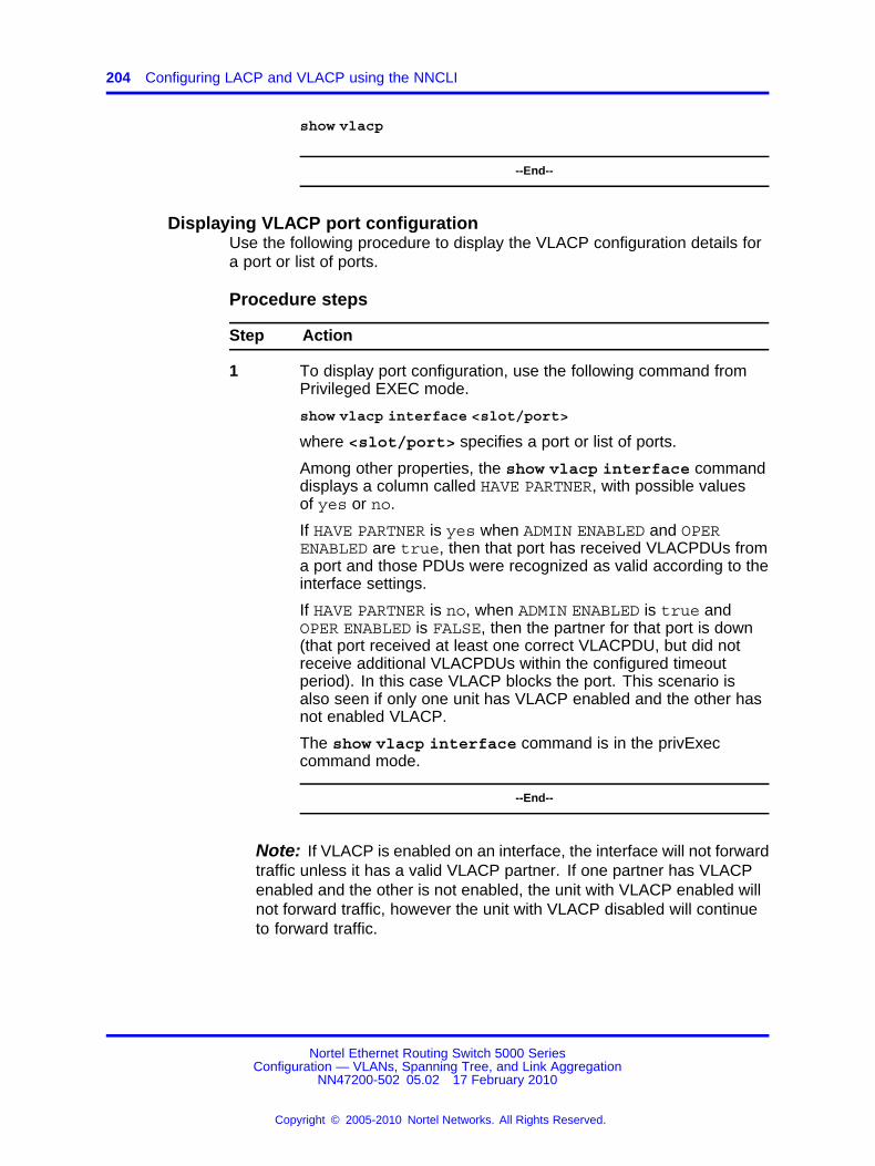
204 Configuring LACP and VLACP using the NNCLI
show vlacp
--End--
Displaying VLACP port configurationUse the following procedure to display the VLACP configuration details fora port or list of ports.
Procedure steps
Step Action
1 To display port configuration, use the following command fromPrivileged EXEC mode.
show vlacp interface <slot/port>
where <slot/port> specifies a port or list of ports.
Among other properties, the show vlacp interface commanddisplays a column called HAVE PARTNER, with possible valuesof yes or no.
If HAVE PARTNER is yes when ADMIN ENABLED and OPERENABLED are true, then that port has received VLACPDUs froma port and those PDUs were recognized as valid according to theinterface settings.
If HAVE PARTNER is no, when ADMIN ENABLED is true andOPER ENABLED is FALSE, then the partner for that port is down(that port received at least one correct VLACPDU, but did notreceive additional VLACPDUs within the configured timeoutperiod). In this case VLACP blocks the port. This scenario isalso seen if only one unit has VLACP enabled and the other hasnot enabled VLACP.
The show vlacp interface command is in the privExeccommand mode.
--End--
Note: If VLACP is enabled on an interface, the interface will not forwardtraffic unless it has a valid VLACP partner. If one partner has VLACPenabled and the other is not enabled, the unit with VLACP enabled willnot forward traffic, however the unit with VLACP disabled will continueto forward traffic.
Nortel Ethernet Routing Switch 5000 SeriesConfiguration — VLANs, Spanning Tree, and Link Aggregation
NN47200-502 05.02 17 February 2010
Copyright © 2005-2010 Nortel Networks. All Rights Reserved.
.

205.
Configuring ADAC using the NNCLI
Configuring ADAC for Nortel IP Phones using the NNCLIYou can configure ADAC-related settings using the NNCLI.
This section covers the following commands:
• “Configuring global ADAC settings” (page 205)
• “Restoring default ADAC settings” (page 206)
• “Configuring autodetection method” (page 208)
• “Resetting autodetection method to default” (page 209)
• “Configuring autodetection for ports” (page 210)
• “Restoring ADAC port settings” (page 210)
• “Adding a range to ADAC MAC address table” (page 210)
• “Restoring ADAC MAC range table” (page 211)
• “Displaying ADAC MAC ranges” (page 212)
• “Displaying ADAC port settings” (page 211)
• “Displaying ADAC MAC ranges” (page 212)
Configuring global ADAC settingsUse the following procedure to configure the global ADAC settings for thedevice.
Procedure steps
Step Action
1 To configure settings, use the following command from GlobalConfiguration mode.
Nortel Ethernet Routing Switch 5000 SeriesConfiguration — VLANs, Spanning Tree, and Link Aggregation
NN47200-502 05.02 17 February 2010
Copyright © 2005-2010 Nortel Networks. All Rights Reserved.
.

206 Configuring ADAC using the NNCLI
[no] adac [enable] [op-mode <untagged-frames-basic |untagged-frames-advanced| tagged-frames>] [trapsenable][voice-vlan <1-4094>] [uplink-port <portlist>][call-server-port <portlist>]
--End--
Variable definitions
Variable Value
enable Enables ADAC on the device.
op-mode<untagged-frames-basic|untagged-frames-advanced |tagged-frames >
Sets the ADAC operation mode to one ofthe following:
• untagged-frames-basic: IP Phonessend untagged frames, and the VoiceVLAN is not created.
• untagged-frames-advanced: IP Phonessend untagged frames, and the VoiceVLAN is created.
• tagged-frames: IP Phones send taggedframes.
traps enable Enables ADAC trap notifications.
voice-vlan <1-4094> Sets the Voice VLAN ID. The assignedVLAN ID must not previously exist.
uplink-port <slot/port> Sets the Uplink port.
uplink-port <portlist> Sets the Uplink ports.
call-server-port <slot/port> Sets the Call Server port.
call-server-port <ports> Sets the Call Server ports.
Restoring default ADAC settingsUse the following procedure to restore the default ADAC settings on thedevice.
Procedure steps
Step Action
1 To restore settings, use the following command from GlobalConfiguration mode.
Nortel Ethernet Routing Switch 5000 SeriesConfiguration — VLANs, Spanning Tree, and Link Aggregation
NN47200-502 05.02 17 February 2010
Copyright © 2005-2010 Nortel Networks. All Rights Reserved.
.

Configuring ADAC for Nortel IP Phones using the NNCLI 207
default adac [enable] [op-mode] [traps enable][voice-vlan] [uplink-port] [call-server-port]
--End--
Variable definitions
Variable Value
enable Restores the default ADAC administrativestate (disabled).
call-server-port Restores the default Call Server port (none).
op-mode Restores the default ADAC operation mode(Untagged Frames Basic).
traps enable Restores the default state for ADACnotifications (enabled).
uplink-port Restores the default Uplink port (none).
voice-vlan Restores the default Voice-VLAN ID (none).
Configuring ADAC per port settingsUse the following procedure to set the per port ADAC settings for thedevice.
Procedure steps
Step Action
1 To configure settings, use the following command from InterfaceConfiguration mode.
[no] adac [port <portlist>] {[enable] [tagged-frames-pvid (<1-4094>|no-change)] [tagged-frames-tagging(tagAll|tagPvidOnly|untagPvidOnly|no-change)]}
--End--
Variable definitions
Variable Value
port <portlist> Ports to which to apply the ADAC configuration.
enable Enables ADAC on the port or ports listed.
Nortel Ethernet Routing Switch 5000 SeriesConfiguration — VLANs, Spanning Tree, and Link Aggregation
NN47200-502 05.02 17 February 2010
Copyright © 2005-2010 Nortel Networks. All Rights Reserved.
.

208 Configuring ADAC using the NNCLI
Variable Value
tagged-frames-pvid<1-4094> | no-change
Sets Tagged-Frames PVID on the port or portslisted.Use no-change to keep the current setting.
tagged-frames-taggingtagAll | tagPvidOnly | untagPvidOnly |no-change
Sets Tagged-Frames Tagging to• tagAll
• tagPvidOnly
• untagPvidOnly
Use no-change to keep the current setting.
Resetting ADAC per port settings to defaultUse the following procedure to set the per port ADAC defaults for thespecified ports.
Procedure steps
Step Action
1 To reset settings, use the following command from InterfaceConfiguration mode.
default adac [port <portlist>] [enable] [tagged-frames-pvid] [tagged-frames-tagging]
--End--
Variable definitions
Variable Value
port <portlist> Ports on which to apply the ADAC defaults.
enable Restores the port to the default ADAC state:Disabled.
tagged-frames-pvid Restores Tagged-Frames PVID on the port orports to the default setting: no-change.
tagged-frames-tagging Restores Tagged-Frames Tagging to defaultsetting: Untag PVID Only.
Configuring autodetection methodUse the following procedure to set the auto-detection method, by MACaddress or using LLDP (IEEE 802.1ab).
Nortel Ethernet Routing Switch 5000 SeriesConfiguration — VLANs, Spanning Tree, and Link Aggregation
NN47200-502 05.02 17 February 2010
Copyright © 2005-2010 Nortel Networks. All Rights Reserved.
.

Configuring ADAC for Nortel IP Phones using the NNCLI 209
Procedure steps
Step Action
1 To configure the autodetection method, use the followingcommand from Interface Configuration mode.
[no] adac detection [port <port-list>] {[mac][lldp]}
--End--
Variable definitions
Variable Value
port <portlist> Specifies the port or ports for which to set thedetection mode.
mac Enables MAC-based detection. The defaultsetting is MAC enabled.
lldp Enables LLDP (802.1ab) detection. The defaultsetting is LLDP enabled.
Resetting autodetection method to defaultUse the following procedure to reset the auto-detection method to itsdefaults. The default is to have both MAC and LLDP enabled.
Procedure steps
Step Action
1 To reset the autodetection method to default, use the followingcommand from Interface Configuration mode.
default adac detection [port <port-list>] {[mac][lldp]}
--End--
Variable definitions
Variable Value
port <portlist> Specifies the port or ports to be returned to thedefault; both MAC and LLDP are enabled.
mac MAC is enabled by default.
lldp LLDP is enabled by default.
Nortel Ethernet Routing Switch 5000 SeriesConfiguration — VLANs, Spanning Tree, and Link Aggregation
NN47200-502 05.02 17 February 2010
Copyright © 2005-2010 Nortel Networks. All Rights Reserved.
.

210 Configuring ADAC using the NNCLI
Configuring autodetection for portsUse the following procedure to enable Auto-Detection on specified ports.
Procedure steps
Step Action
1 To configure autodetection, use the following command fromInterface Configuration mode.
[no] adac port <port-list> enable
--End--
Restoring ADAC port settingsUse the following procedure to restore the default ADAC setting (disabled)for the specified ports.
Procedure steps
Step Action
1 To restore ADAC port settings, use the following command fromGlobal Configuration mode.
default adac [port <port-list>] enable
--End--
Adding a range to ADAC MAC address tableUse the following procedure to add a specified range to the table of MACaddresses recognized as Nortel IP Phones by the Auto-Detection process.
Procedure steps
Step Action
1 To add a range, use the following command from GlobalConfiguration mode.
[no] adac mac-range-table low-end <MACaddress> high-end<MACaddress>
Nortel Ethernet Routing Switch 5000 SeriesConfiguration — VLANs, Spanning Tree, and Link Aggregation
NN47200-502 05.02 17 February 2010
Copyright © 2005-2010 Nortel Networks. All Rights Reserved.
.

Configuring ADAC for Nortel IP Phones using the NNCLI 211
Use the no form of the command to delete a range.
Note: If the low-end and high-end MAC address values arenot provided, the switch deletes all existing MAC addressranges from the switch.
--End--
Restoring ADAC MAC range tableUse the following procedure to restore all supported MAC address rangeson the switch to their default values.
Procedure steps
Step Action
1 To restore the ADAC MAC range table, use the followingcommand in Global Configuration mode.
default adac mac-range-table
--End--
Displaying global ADAC settingsUse the following procedure to display the global ADAC settings for thedevice.
Procedure steps
Step Action
1 To display global ADAC settings, use the following commandfrom Privileged EXEC mode.
show adac
--End--
Displaying ADAC port settingsUse the following procedure to display the ADAC settings for a particularport.
Nortel Ethernet Routing Switch 5000 SeriesConfiguration — VLANs, Spanning Tree, and Link Aggregation
NN47200-502 05.02 17 February 2010
Copyright © 2005-2010 Nortel Networks. All Rights Reserved.
.

212 Configuring ADAC using the NNCLI
Procedure steps
Step Action
1 To display ADAC port settings, use the following command fromPrivileged EXEC mode.
show adac interface <interface-type> <slot/port>
--End--
Displaying ADAC MAC rangesUse the following procedure to display the ADAC MAC ranges configuredon the switch.
Procedure steps
Step Action
1 To display ADAC MAC ranges, use the following command fromPrivileged EXEC mode.
show adac mac-range-table
--End--
Displaying configured detection mechanismUse the following procedure to display the detection mechanismconfigured per port.
Procedure steps
Step Action
1 To display the detection mechanism, use the following commandfrom Privileged EXEC mode.
show adac detection interface [<interface-type>][<interface-id>]
--End--
Nortel Ethernet Routing Switch 5000 SeriesConfiguration — VLANs, Spanning Tree, and Link Aggregation
NN47200-502 05.02 17 February 2010
Copyright © 2005-2010 Nortel Networks. All Rights Reserved.
.

Configuring ADAC for Nortel IP Phones using the NNCLI 213
ADAC UFA configuration exampleFigure 34 "ADAC UFA configuration example" (page 213) shows anexample of ADAC configured in Untagged-Frames-Advanced (UFA)op-mode. (Call-server-port is used in this example, because the server isdirectly connected to the 5000 series switch.)
Figure 34ADAC UFA configuration example
Auto-Configuration (AC) is applied for call-server-port and telephonyports. On telephony ports, AC is applied only when Nortel IP Phones aredetected. (Auto-detection is based on MAC Address.) VLAN configurationis made according to the selected op-mode (UFA):
• Telephony port:
— - Membership = remove from all other VLANs, and add toVoice-VLAN (since there is no reason for the port to be memberof more than the Voice VLAN)
— Tagging = Untagged
— PVID = Voice-VLAN
• Call Server port:
— Membership = add to Voice-VLAN
— Tagging = Untagged
— PVID = Voice-VLAN
To configure the example shown in Figure 34 "ADAC UFA configurationexample" (page 213), you must perform the following tasks:
Step Action
1 Configure the call-server port.
Nortel Ethernet Routing Switch 5000 SeriesConfiguration — VLANs, Spanning Tree, and Link Aggregation
NN47200-502 05.02 17 February 2010
Copyright © 2005-2010 Nortel Networks. All Rights Reserved.
.

214 Configuring ADAC using the NNCLI
2 Configure voice-VLAN.
3 Configure Untagged-Frames-Advanced (UFA) op-mode.
4 Enable ADAC on all ports to which IP phones connect.
5 Configure IP phones to send untagged traffic.
6 Enable the LLDP-MED Capabilities TLV on the ports used by IPphones.
7 Enable the LLDP-MED Network Policy TLV for transmission.
This prevents configuration mismatches by enabling the IPPhone to obtain its policy settings directly from the switch.
--End--
ADAC configuration commandsThe following section describes the detailed NNCLI commands required tocarry out the configuration shown in Figure 34 "ADAC UFA configurationexample" (page 213).
(config)#adac call-server-port 7(config)#adac voice-vlan 2(config)#adac enable op-mode untagged-frames-advanced(config)#interface fastEthernet all(config)#interface fastEthernet 16,24 enable(config-if)#lldp tx-tlv port 16,24 med med-capabilities(config-if)#lldp tx-tlv port 16,24 med network-policy
Verifying new ADAC settingsThe following section includes commands used to view ADACconfiguration settings and the expected responses for each.
Auto configuration settings(config)#show adac interface 7,16,24
Port Auto-Detection Auto-Configuration---- -------------- ------------------7 Disabled Applied16 Enabled Applied24 Enabled Applied
VLAN settings(config)#show vlan
Id Name Type Protocol User PID Active IVL/SVL Mgmt ----------------------- -------- ---------------- -------- ------1 VLAN #1 Port None 0x0000 Yes IVL Yes Port Members: 1-15,17-232 Voice_VLAN Port None 0x0000 Yes IVL No Port Members: 7,16,24(config)#show vlan interface info 7,16,24
Nortel Ethernet Routing Switch 5000 SeriesConfiguration — VLANs, Spanning Tree, and Link Aggregation
NN47200-502 05.02 17 February 2010
Copyright © 2005-2010 Nortel Networks. All Rights Reserved.
.

Configuring ADAC for Nortel IP Phones using the NNCLI 215
Filter FilterUntagged Unregistered Port Frames Frames PVID PRI TaggingName ---- -------- ------------ ---- --- -----------------------------7 No Yes 2 0 UntagAll Port 716 No Yes 2 0 UntagAll Port 1624 No Yes 2 0 UntagAll Port 24
ADAC settings(config)#show running-config
!...! *** ADAC *** Note information in this section.!no adac enableno adac mac-range-tableinterface FastEthernet ALLadac port 24 enableno adac port 1-23 enableexitadac mac-range-table low-end 00-0A-E4-01-10-20 high-end00-0A-E4-01-23-A7adac mac-range-table low-end 00-0A-E4-01-70-EC high-end00-0A-E4-01-84-73adac mac-range-table low-end 00-0A-E4-01-A1-C8 high-end00-0A-E4-01-AD-7Fadac mac-range-table low-end 00-0A-E4-01-DA-4E high-end00-0A-E4-01-ED-D5adac mac-range-table low-end 00-0A-E4-02-1E-D4 high-end00-0A-E4-02-32-5Badac mac-range-table low-end 00-0A-E4-02-5D-22 high-end00-0A-E4-02-70-A9adac mac-range-table low-end 00-0A-E4-02-D8-AE high-end00-0A-E4-02-FF-BDadac mac-range-table low-end 00-0A-E4-03-87-E4 high-end00-0A-E4-03-89-0Fadac mac-range-table low-end 00-0A-E4-03-90-E0 high-end00-0A-E4-03-B7-EFadac mac-range-table low-end 00-0A-E4-04-1A-56 high-end00-0A-E4-04-41-65adac mac-range-table low-end 00-0A-E4-04-80-E8 high-end00-0A-E4-04-A7-F7adac mac-range-table low-end 00-0A-E4-04-D2-FC high-end00-0A-E4-05-48-2Badac mac-range-table low-end 00-0A-E4-05-B7-DF high-end00-0A-E4-06-05-FEadac mac-range-table low-end 00-0A-E4-06-55-EC high-end00-0A-E4-07-19-3Badac mac-range-table low-end 00-0A-E4-08-0A-02 high-end00-0A-E4-08-7F-31adac mac-range-table low-end 00-0A-E4-08-B2-89 high-end
Nortel Ethernet Routing Switch 5000 SeriesConfiguration — VLANs, Spanning Tree, and Link Aggregation
NN47200-502 05.02 17 February 2010
Copyright © 2005-2010 Nortel Networks. All Rights Reserved.
.

216 Configuring ADAC using the NNCLI
00-0A-E4-09-75-D8adac mac-range-table low-end 00-0A-E4-09-BB-9D high-end00-0A-E4-09-CF-24adac mac-range-table low-end 00-0A-E4-09-FC-2B high-end00-0A-E4-0A-71-5Aadac mac-range-table low-end 00-0A-E4-0A-9D-DA high-end00-0A-E4-0B-61-29adac mac-range-table low-end 00-0A-E4-0B-BB-FC high-end00-0A-E4-0B-BC-0Fadac mac-range-table low-end 00-0A-E4-0B-D9-BE high-end00-0A-E4-0C-9D-0Dadac traps enableadac voice-vlan 2adac call-server-port 7no adac uplink-portadac op-mode untagged-frames-advancedadac enable
Nortel Ethernet Routing Switch 5000 SeriesConfiguration — VLANs, Spanning Tree, and Link Aggregation
NN47200-502 05.02 17 February 2010
Copyright © 2005-2010 Nortel Networks. All Rights Reserved.
.

217.
Configuring VLANs using DeviceManager
The following sections detail how to create and manage a VLAN using theDevice Manager (DM). VLAN creation and management is performed inthe VLANs dialog box.
The VLAN Basic tab fields are described in the following table.
Table 19VLAN Basic tab
Field Description
Id The VLAN ID for the VLAN.
Name Name of the VLAN.
Ifindex Displays port numbers.
Color An administratively assigned color code for the VLAN.The value of this object is used by the VLAN ManagerGUI tool to select a color when it draws this VLAN onthe screen.
Type Indicates the type of VLAN: byPort or byProtocolId.
PortMembers Ports that are members of the VLAN.
ActiveMembers Set of ports that are currently active in the VLAN.Active ports include all static ports and any dynamicports where the VLAN policy was met.
StgId Identifies the spanning tree group to which the VLANbelongs. This field is only available when the switch isrunning in Nortel STPG mode.
MstpInstance This field is only available when the switch is runningin MSTP mode.
ProtocolId Protocol for protocol-based VLANs. This value is takenfrom the Assigned Numbers RFC. For port-basedVLANs, None is the displayed value.
Nortel Ethernet Routing Switch 5000 SeriesConfiguration — VLANs, Spanning Tree, and Link Aggregation
NN47200-502 05.02 17 February 2010
Copyright © 2005-2010 Nortel Networks. All Rights Reserved.
.

218 Configuring VLANs using Device Manager
Table 19VLAN Basic tab (cont’d.)
Field Description
UserDefinedPid When rcVlanProtocolId is set to usrDefined(15) in aprotocol-based VLAN, this field represents the 16-bituser-defined protocol identifier.
Encap The type of encapsulation. Options are ethernet2 andllc.
MacAddress The unique hardware address of the device.
Routing Specifies whether routing is enabled (true) or disabled(false) on the VLAN.
This section contains information about the following topics:
• “Configuring VLAN settings” (page 218)
• “Enabling AutoPVID” (page 219)
• “Creating a VLAN” (page 220)
• “Modifying a VLAN” (page 221)
• “Deleting VLANs” (page 221)
• “Configuring VLAN port properties” (page 222)
• “Configuring IGMP snooping” (page 223)
• “Assigning an IP address to a VLAN” (page 223)
• “Configuring VLAN DHCP” (page 225)
Configuring VLAN settingsTo configure VLAN settings, use the following procedure.
Procedure steps
Step Action
1 From the Device Manager, click VLAN.
2 Select VLANs. The VLAN dialog box opens.
3 Click the Settings tab. The VLAN Settings tab appears.
--End--
Nortel Ethernet Routing Switch 5000 SeriesConfiguration — VLANs, Spanning Tree, and Link Aggregation
NN47200-502 05.02 17 February 2010
Copyright © 2005-2010 Nortel Networks. All Rights Reserved.
.
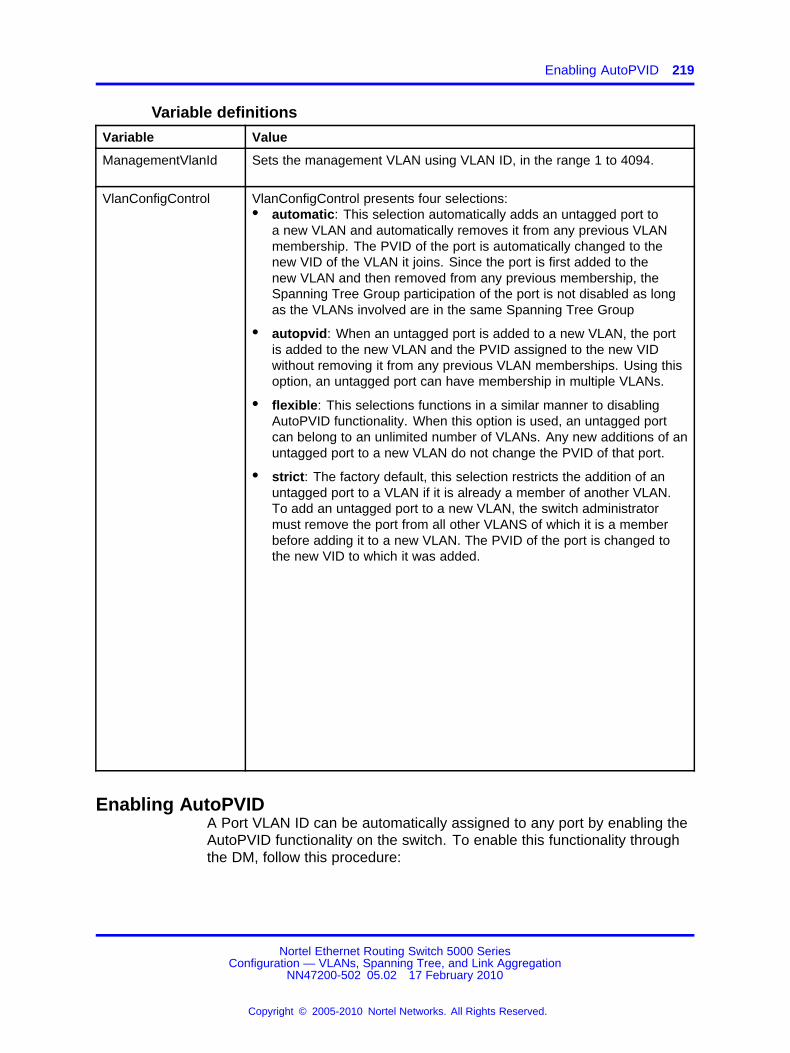
Enabling AutoPVID 219
Variable definitions
Variable Value
ManagementVlanId Sets the management VLAN using VLAN ID, in the range 1 to 4094.
VlanConfigControl VlanConfigControl presents four selections:• automatic: This selection automatically adds an untagged port to
a new VLAN and automatically removes it from any previous VLANmembership. The PVID of the port is automatically changed to thenew VID of the VLAN it joins. Since the port is first added to thenew VLAN and then removed from any previous membership, theSpanning Tree Group participation of the port is not disabled as longas the VLANs involved are in the same Spanning Tree Group
• autopvid: When an untagged port is added to a new VLAN, the portis added to the new VLAN and the PVID assigned to the new VIDwithout removing it from any previous VLAN memberships. Using thisoption, an untagged port can have membership in multiple VLANs.
• flexible: This selections functions in a similar manner to disablingAutoPVID functionality. When this option is used, an untagged portcan belong to an unlimited number of VLANs. Any new additions of anuntagged port to a new VLAN do not change the PVID of that port.
• strict: The factory default, this selection restricts the addition of anuntagged port to a VLAN if it is already a member of another VLAN.To add an untagged port to a new VLAN, the switch administratormust remove the port from all other VLANS of which it is a memberbefore adding it to a new VLAN. The PVID of the port is changed tothe new VID to which it was added.
Enabling AutoPVIDA Port VLAN ID can be automatically assigned to any port by enabling theAutoPVID functionality on the switch. To enable this functionality throughthe DM, follow this procedure:
Nortel Ethernet Routing Switch 5000 SeriesConfiguration — VLANs, Spanning Tree, and Link Aggregation
NN47200-502 05.02 17 February 2010
Copyright © 2005-2010 Nortel Networks. All Rights Reserved.
.

220 Configuring VLANs using Device Manager
Procedure steps
Step Action
1 From the menu, select Edit > Chassis.
The Chassis dialog box appears with the System tab selected.
2 On the System tab, select enabled in the AutoPVID field.
3 Click Apply.
--End--
Creating a VLANTo create a VLAN, follow this procedure:
The new VLAN is created and displayed in the VLANs Basic tab. To addor remove ports from the VLAN, the VLAN must be modified.
Procedure steps
Step Action
1 From the DM menu, select VLAN > VLANs.
The VLANs dialog box appears.
2 Click Insert.
The Insert Basic dialog box appears with the Type field set tobyPort.
3 Enter the identifier for the VLAN in the Id field. This value mustbe a unique number between 2 and 4094.
4 Optionally, enter a name for the VLAN in the Name field.
5 Optionally, assign a color identifier to the VLAN in the Colorfield.
6 Enter the value of the Spanning Tree Group to which the VLANwill belong in the StgId field.
7 When in Nortel STPG mode, use the StgId menu to choose thespanning tree group to which the VLAN is to belong. When inMSTP mode, use the MstpInstance list to select the CIST orMSTI instance to which the VLAN is to belong.
8 Select the type of VLAN in the Type field.
a If the VLAN is to be port-based, select the byPort optionbutton.
b If the VLAN is to be protocol-based, select the byProtocolIdoption button. This selection enables the ProtocolId field.
Nortel Ethernet Routing Switch 5000 SeriesConfiguration — VLANs, Spanning Tree, and Link Aggregation
NN47200-502 05.02 17 February 2010
Copyright © 2005-2010 Nortel Networks. All Rights Reserved.
.

Deleting VLANs 221
From this field select the protocol on which this VLAN will bebased. If it is to be based on a user-defined protocol, selectthe usrDefined option button and enter the custom PID in theUserDefinedPid field.
9 Click Insert.
--End--
Modifying a VLANAfter a VLAN is created, four types of information can be modified withoutthe need to recreate the VLAN:
1. VLAN Name
2. Color Identifier
3. Member Ports
4. Routing status
To change the VLAN name, color identifier, or routing status, click in theappropriate fields in the VLANs Basic tab and then click Apply .
To change the VLAN member ports, follow this procedure:
The VLANs Basic tab refreshes with the correct port numbers listed in thePortMembers field.
Procedure steps
Step Action
1 In the row that represents the VLAN that is to be modified,double-click in the PortMembers field.
The Port Members screen appears.
2 Click the buttons that correspond to the ports that are to beadded or deleted from the VLAN. Click All to select all switchports.
3 Click OK.
4 Click Apply.
--End--
Deleting VLANsUse the following procedure to delete a VLAN.
Nortel Ethernet Routing Switch 5000 SeriesConfiguration — VLANs, Spanning Tree, and Link Aggregation
NN47200-502 05.02 17 February 2010
Copyright © 2005-2010 Nortel Networks. All Rights Reserved.
.

222 Configuring VLANs using Device Manager
Procedure steps
Step Action
1 From the DM menu, select VLAN > VLANs.
The VLANs dialog box appears with the Basic tab selected.
2 Select the VLAN to be deleted.
3 Click Delete.
The DM deletes the selected VLAN.
--End--
Configuring VLAN port propertiesThe Port - VLAN tab displays the VLAN membership for a port.
Use the following procedure to view the Port - VLAN tab:
Procedure steps
Step Action
1 From the Device View, select the port to edit.
2 From the menu, chooseEdit > Port.
The Port dialog box appears.
3 Select the VLAN tab.
4 Click Apply after making any changes.
--End--
Variable definitions
Variable Value
VlanIds The VLANIDs of which this port is a member.
DiscardUntaggedFrames This field only applies to trunk ports. It actsas a flag used to determine how to processuntagged frames received on this port. Whenthe flag is set, the frames are discarded by theforwarding process. When the flag is reset, theframes are assigned to the VLAN specified byrcVlanPortDefaultVlanId.
Nortel Ethernet Routing Switch 5000 SeriesConfiguration — VLANs, Spanning Tree, and Link Aggregation
NN47200-502 05.02 17 February 2010
Copyright © 2005-2010 Nortel Networks. All Rights Reserved.
.
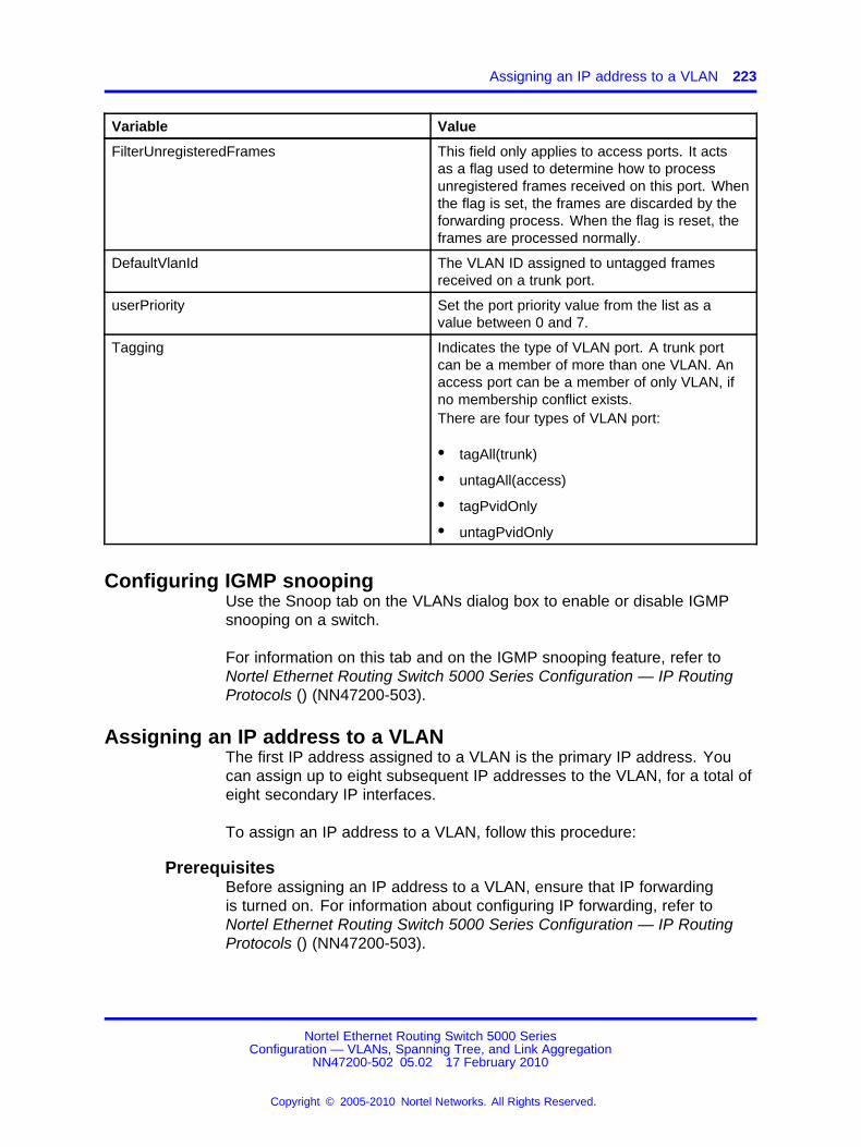
Assigning an IP address to a VLAN 223
Variable Value
FilterUnregisteredFrames This field only applies to access ports. It actsas a flag used to determine how to processunregistered frames received on this port. Whenthe flag is set, the frames are discarded by theforwarding process. When the flag is reset, theframes are processed normally.
DefaultVlanId The VLAN ID assigned to untagged framesreceived on a trunk port.
userPriority Set the port priority value from the list as avalue between 0 and 7.
Tagging Indicates the type of VLAN port. A trunk portcan be a member of more than one VLAN. Anaccess port can be a member of only VLAN, ifno membership conflict exists.There are four types of VLAN port:
• tagAll(trunk)
• untagAll(access)
• tagPvidOnly
• untagPvidOnly
Configuring IGMP snoopingUse the Snoop tab on the VLANs dialog box to enable or disable IGMPsnooping on a switch.
For information on this tab and on the IGMP snooping feature, refer toNortel Ethernet Routing Switch 5000 Series Configuration — IP RoutingProtocols () (NN47200-503).
Assigning an IP address to a VLANThe first IP address assigned to a VLAN is the primary IP address. Youcan assign up to eight subsequent IP addresses to the VLAN, for a total ofeight secondary IP interfaces.
To assign an IP address to a VLAN, follow this procedure:
PrerequisitesBefore assigning an IP address to a VLAN, ensure that IP forwardingis turned on. For information about configuring IP forwarding, refer toNortel Ethernet Routing Switch 5000 Series Configuration — IP RoutingProtocols () (NN47200-503).
Nortel Ethernet Routing Switch 5000 SeriesConfiguration — VLANs, Spanning Tree, and Link Aggregation
NN47200-502 05.02 17 February 2010
Copyright © 2005-2010 Nortel Networks. All Rights Reserved.
.

224 Configuring VLANs using Device Manager
Procedure steps
Step Action
1 From the DM menu, select VLAN > VLANs.
The VLANs dialog box appears.
2 Highlight the VLAN to which an IP address is to be assigned.
3 Click IP. The IP VLAN dialog box appears with the IP Addresstab selected.
4 Click Insert. The Insert IP Address dialog box appears.
5 Type the IP Address, Subnet Mask, and Mac Address Offsetin the fields provided.
6 Click Insert.
--End--
Variable definitions
Variable Value
IpAddress The device IP address.
NetMask The subnet mask address.
BcastAddrFormat The IP broadcast address format used on thisinterface.
ReasmMaxSize The size of the largest IP datagram whichthis entity can re-assemble from incomingIP fragmented datagrams received on thisinterface
VlanId The VLAN number. A value of -1 indicates thatthe VLAN ID is ignored.
MacOffset Used to translate the IP address into a MACaddress. You can either mention a MAC offsetwhile configuring an IP on the VLAN or it canbe allotted by the system within the aboverange.
SecondaryIf The SecondaryIf field is set to True if theVLAN IP address is a secondary IP addressand False if the IP address for the VLAN is theprimary IP address.
Configuring the IP multicast filter tableUse the following procedure to configure the IP multicast filter table.
Nortel Ethernet Routing Switch 5000 SeriesConfiguration — VLANs, Spanning Tree, and Link Aggregation
NN47200-502 05.02 17 February 2010
Copyright © 2005-2010 Nortel Networks. All Rights Reserved.
.

Configuring VLAN DHCP 225
Procedure steps
Step Action
1 From the Device Manager menu, select VLAN > VLANs. TheVLANs dialog box appears.
2 Select the IP Address Multicast Filter Table tab.
3 Click Insert.
4 Enter the allowed IP address in either IPv4 or IPv6 format.
5 Click Insert.
6 To remove an address, select it in the table and click Delete.Confirm the action when prompted.
--End--
Configuring VLAN DHCPTo configure DHCP for a VLAN, follow this procedure:
PrerequisitesBefore you can view the DHCP tab, you must first enable routing on theswitch. For more information about IP routing configuration, refer to NortelEthernet Routing Switch 5000 Series Configuration - IP Routing Protocols(), part number NN47200-503.
Procedure steps
Step Action
1 From the DM menu, select VLAN > VLANs.
The VLANs dialog box appears.
2 Highlight the VLAN for which DHCP is to be configured.
3 Click IP.
The IP VLAN screen appears.
4 Select the DHCP tab.
5 Make changes as necessary in the fields provided.
6 Click Apply.
--End--
Nortel Ethernet Routing Switch 5000 SeriesConfiguration — VLANs, Spanning Tree, and Link Aggregation
NN47200-502 05.02 17 February 2010
Copyright © 2005-2010 Nortel Networks. All Rights Reserved.
.

226 Configuring VLANs using Device Manager
Variable definitions
Variable Value
Enable Specifies whether DHCP is enabled ordisabled.
MinSec Indicates the minimum number of secondsto wait between receiving a DHCP packetand actually forwarding the DHCP packetto the destination device. A value of zero(0) indicates forwarding is done immediatelywithout any delay.
Mode Indicates what type of DHCP packets thisinterface supports. A value of none (1) resultsin all incoming DHCP and BOOTP packetsbeing dropped.
AlwaysBroadcast Indicates if DHCP Reply packets are broadcastto the DHCP client on this interface.
Clearing DHCP statistics counters on a VLANUse the following procedure to clear DHCP statistics counters.
Procedure steps
Step Action
1 From the Device Manager menu, select VLAN > VLANs.
The VLANs dialog box appears.
2 Highlight the VLAN for which DHCP statistics counters are to becleared.
3 Click IP.
The IP VLAN screen appears.
4 Select the DCHP tab.
5 From the DHCP tab, select clear in the ClearCounters field andpress Apply.
--End--
Graphing DHCP statisticsUse the following procedure to graph DHCP statistics:
Nortel Ethernet Routing Switch 5000 SeriesConfiguration — VLANs, Spanning Tree, and Link Aggregation
NN47200-502 05.02 17 February 2010
Copyright © 2005-2010 Nortel Networks. All Rights Reserved.
.

Configuring NSNA per VLAN 227
Procedure steps
Step Action
1 From the DHCP tab, click Graph.
The DCHP tab for graphing appears.
--End--
Variable definitions
Variable Value
NumRequests The total number of DHCP requests seen onthis interface.
NumReplies The total number of DHCP replies seen on thisinterface.
Configuring NSNA per VLANTo configure NSNA for a VLAN, use the procedure in this section.
ATTENTION
VLANs that you plan to configure as Nortel SNA VLANs must be empty(that is, they have no port members assigned). Nortel SNA VLANs cannotbe associated with non-Nortel SNA ports; therefore you cannot assignnon-NSNA ports manually to enabled NSNA VLANs.
Dumb and static devices that cannot authenticate through tunnel guardcan be connected to NSNA dynamic ports. To ensure network access forthese devices, add the MAC addresses to the SNAS MAC database.
For more information about Nortel SNA, refer to Nortel Ethernet RoutingSwitch 5000 Series Configuration - Security (), NN47200-501.
Procedure steps
Step Action
1 From the Device Manager main menu, select VLAN. The VLANmenu opens.
2 Select VLAN. The VLAN dialog appears with the Basic tab open.
3 Select the NSNA tab.
4 Select a VLAN to modify.
5 Double click the NsnaColor field. A menu appears.
Nortel Ethernet Routing Switch 5000 SeriesConfiguration — VLANs, Spanning Tree, and Link Aggregation
NN47200-502 05.02 17 February 2010
Copyright © 2005-2010 Nortel Networks. All Rights Reserved.
.

228 Configuring VLANs using Device Manager
6 Select one of the following options from the menu:
• none
• red
• green
• yellow
• voip
ATTENTIONAlthough each switch can have multiple Yellow, Green, and VoIPVLANs, each switch must have only one Red VLAN.
7 In the other columns, enter parameters compatible with theNsnaColor selection.
8 Click Apply.
--End--
Variable definitions
Variable Value
Id Specifies the VLAN identification number.
NsnaColor Specifies the NSNA VLAN color.
FilterSetName Specifies the filter set name.Note: NsnaColor field must be only red, yellow, or green.
YellowSubnetType Specifies the Ethernet type for the Yeloow VLAN subnet.Note: NsnaColor field must be set to yellow.
YellowSubnet Specifies the Yellow VLAN subnet.Note: NsnaColor field must be set to yellow.
YellowSubnetMask Specifies the Yellow VLAN subnet mask.Note: NsnaColor field must be set to yellow..
Deleting an NSNA VLANTo remove an NSNA VLAN, use the procedure in this section.
PrerequisitesNSNA must be globally disabled before you can delete an NSNA VLAN.
Procedure steps
Step Action
1 To globally disable NSNA, from the Device Manager menu,select Edit.
Nortel Ethernet Routing Switch 5000 SeriesConfiguration — VLANs, Spanning Tree, and Link Aggregation
NN47200-502 05.02 17 February 2010
Copyright © 2005-2010 Nortel Networks. All Rights Reserved.
.

Filtering an NSNA VLAN 229
2 Select Security.
3 Select NSNA. The NSNA dialog appears with the NSNAS tabopen.
4 Select the Globals tab.
5 Clear the Enabled check box.
6 From the Device Manager menu, select VLAN. The VLAN dialogappears with the Basic tab open.
7 Select the NSNA tab.
8 Select the VLAN to delete and double click the NsnaColor field.
9 From the list, select none.
10 Click Apply.
11 Select the Basic tab.
12 Select the VLAN to delete (the VLAN for which the NsnaColorwas changed to none).
13 Click Delete.
--End--
Filtering an NSNA VLANTo filter an NSNA VLAN, use the following procedure.
Procedure steps
Step Action
1 From the Device Manager main menu, select VLAN. The VLANmenu appears.
2 From the VLAN menu, select VLANs. The VLAN dialog appearswith the Basic tab open.
3 Select NSNA.
4 Click Filter. The VLAN, NSNA - Filter dialog opens.
5 Set the filter parameters.
6 Click Filter.
--End--
Nortel Ethernet Routing Switch 5000 SeriesConfiguration — VLANs, Spanning Tree, and Link Aggregation
NN47200-502 05.02 17 February 2010
Copyright © 2005-2010 Nortel Networks. All Rights Reserved.
.
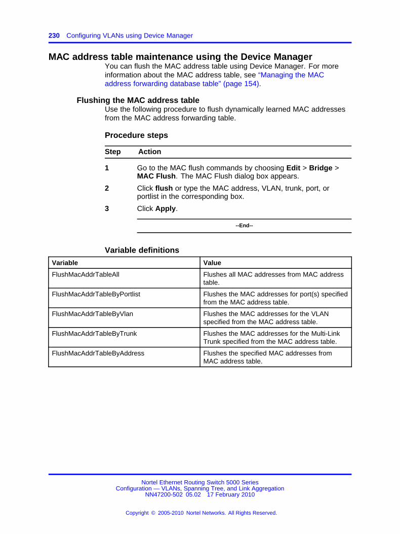
230 Configuring VLANs using Device Manager
MAC address table maintenance using the Device ManagerYou can flush the MAC address table using Device Manager. For moreinformation about the MAC address table, see “Managing the MACaddress forwarding database table” (page 154).
Flushing the MAC address tableUse the following procedure to flush dynamically learned MAC addressesfrom the MAC address forwarding table.
Procedure steps
Step Action
1 Go to the MAC flush commands by choosing Edit > Bridge >MAC Flush. The MAC Flush dialog box appears.
2 Click flush or type the MAC address, VLAN, trunk, port, orportlist in the corresponding box.
3 Click Apply.
--End--
Variable definitions
Variable Value
FlushMacAddrTableAll Flushes all MAC addresses from MAC addresstable.
FlushMacAddrTableByPortlist Flushes the MAC addresses for port(s) specifiedfrom the MAC address table.
FlushMacAddrTableByVlan Flushes the MAC addresses for the VLANspecified from the MAC address table.
FlushMacAddrTableByTrunk Flushes the MAC addresses for the Multi-LinkTrunk specified from the MAC address table.
FlushMacAddrTableByAddress Flushes the specified MAC addresses fromMAC address table.
Nortel Ethernet Routing Switch 5000 SeriesConfiguration — VLANs, Spanning Tree, and Link Aggregation
NN47200-502 05.02 17 February 2010
Copyright © 2005-2010 Nortel Networks. All Rights Reserved.
.

231.
Configuring STP using Device Manager
Setting the STP mode using Device ManagerTo set the STP operational mode using Device Manager:
Procedure steps
Step Action
1 From the Device Manager menu bar, choose VLAN > SpanningTree > Globals.
The Spanning Tree dialog box appears with the Globals tabdisplayed.
2 In the SpanningTreeAdminMode field, select the STP mode.The available modes are:
• nortelStpg
• rstp
• mstp
3 Click Apply.
A warning message appears reminding you that you must resetthe switch for the change to take effect.
4 Click Yes.
5 Click Close.
6 To reset the switch, choose Edit > Chassis.
7 From the System tab, choose the reboot option and clickApply.
--End--
Configuring STP BPDU Filtering using Device ManagerYou can use the STP BPDU-Filtering tab to configure STP BPDU Filteringon a port. This tab is available in all three STP modes.
Nortel Ethernet Routing Switch 5000 SeriesConfiguration — VLANs, Spanning Tree, and Link Aggregation
NN47200-502 05.02 17 February 2010
Copyright © 2005-2010 Nortel Networks. All Rights Reserved.
.

232 Configuring STP using Device Manager
To configure STP BPDU Filtering:
Procedure steps
Step Action
1 From the Device Manager menu, choose Edit > Port.
The Port dialog box appears with the Interface tab displayed.
2 Click the STP BPDU-Filtering tab.
The STP BPDU-Filtering tab appears.
--End--
Variable definitions
Variable Value
AdminEnabled Enables and disables BPDU filtering on theport.
OperEnabled Indicates the current operational status ofBPDU filtering on the port: true (enabled) orfalse (disabled).
Timeout When BPDU filtering is enabled, this indicatesthe time (in 1/100 seconds) during which theport remains disabled after it receives a BPDU.The port timer is disabled if this value is set to0. The default value is 12000 (120 seconds).
TimerCount Displays the time remaining for the port to stayin the disabled state after receiving a BPDU.
Creating and Managing STGs using Device ManagerYou can use the Device Manager (DM) screens detailed in this section tocreate and manage Spanning Tree Groups.
Note: The STG dialog boxes and tabs described in this section areaccessible only when the STP mode is set to Nortel STPG.
To configure STGs using Device Manager, refer to the following:
• “Configuring STG global properties” (page 233)
• “Creating an STG” (page 234)
• “Adding a VLAN to an STG” (page 235)
• “Moving a VLAN between STGs” (page 236)
• “Deleting an STG” (page 236)
Nortel Ethernet Routing Switch 5000 SeriesConfiguration — VLANs, Spanning Tree, and Link Aggregation
NN47200-502 05.02 17 February 2010
Copyright © 2005-2010 Nortel Networks. All Rights Reserved.
.

Creating and Managing STGs using Device Manager 233
• “Displaying STG Status” (page 236)
• “Displaying STG ports” (page 237)
• “Configuring STG port properties” (page 238)
Configuring STG global propertiesTo configure the STG global properties:
Procedure steps
Step Action
1 From the Device Manager menu, choose VLAN > SpanningTree > STG.
The STG dialog box appears with the Globals tab displayed.
2 Select the STP path cost calculation mode:
• ieee802dot1dCompatible
• ieee802dot1tCompatible
3 Select the STP port mode:
• normal
• auto
4 Check the SpanningTreeAdminCompatibility box to enable802.1d port learning.
5 Click Apply.
describes the fields in the STG Globals tab.
--End--
Variable definitions
Variable Value
SpanningTreePathCostCalculationMode This object indicates thecurrent spanning-tree pathcost calculation mode. The valueieee802dot1dCompatible is validonly when the switch is running inNortel STPG mode.
SpanningTreePortMode This object sets the STG portmembership mode for allSpanning Tree Groups onthe switch.
Nortel Ethernet Routing Switch 5000 SeriesConfiguration — VLANs, Spanning Tree, and Link Aggregation
NN47200-502 05.02 17 February 2010
Copyright © 2005-2010 Nortel Networks. All Rights Reserved.
.

234 Configuring STP using Device Manager
Variable Value
SpanningTreeAdminCompatibility This field Indicates whether thelearning mode of a port stays inthe Forwarding state or changesto the Disabled state when theport operation status goes down.If the box is checked, the portgoes to the disabled state whendown.
SpanningTreeOperCompatibility This field indicates theoperational compatibility modefor features controlled by theassociated object.
Creating an STGTo create a Spanning Tree Group:
The new STG is displayed in the STG Configuration tab.
Procedure steps
Step Action
1 From the Device Manager menu, choose VLAN > SpanningTree > STG.
The STG dialog box appears with the Globals tab displayed.
2 Click the Configuration tab.
The Configuration tab appears.
3 Click Insert.
The Insert Configuration dialog box appears.
4 In the fields provided, fill in the information for the new STG.
describes the fields in the Configuration tab.
5 Click Insert.
--End--
Variable definitions
Variable Value
Id Enter an integer between 1 and 8 thatidentifies the STG; 1 is the default STG.
Nortel Ethernet Routing Switch 5000 SeriesConfiguration — VLANs, Spanning Tree, and Link Aggregation
NN47200-502 05.02 17 February 2010
Copyright © 2005-2010 Nortel Networks. All Rights Reserved.
.

Creating and Managing STGs using Device Manager 235
Variable Value
BridgeAddress Displays the MAC address used by this bridge;it is usually the smallest MAC address of allports in the bridge.
NumPorts Displays the number of ports controlled by thisbridging entity.
ProtocolSpecification Displays the version of spanning tree that isrunning.
Priority Enter the first two octets of the 8-octet bridgeID; the range is 0 to 65 535.
BridgeMaxAge Enter the maximum time you want to allowbefore the specified STG times out, inseconds; the range is 600 to 4 000.
BridgeHelloTime Enter the maximum time between hellos, inseconds; the range is 100 to 1 000.
BridgeForwardDelay Enter the maximum delay in forwarding, inseconds; the range is 400 to 3 000.
EnableStp Enables or disables the spanning tree group.
TaggedBpduAddress The address for the tagged BPDU.
TaggedBpduVlanId Enter the VLAN ID for tagged BPDUs.
Adding a VLAN to an STGWhen using Device Manager, a VLAN can only be added to an STG at thetime the VLAN is created.
To add a VLAN to an STG:
Procedure steps
Step Action
1 If it does not already exist, create the STG to which you want toadd the VLAN.
See “Creating an STG” (page 234) for more information aboutcreating STGs.
2 Create the VLAN, making sure to select the desired StgId on theInsert VLAN screen.
3 Open the VLAN dialog box and view the Basic tab to confirmthat the StgId field for the VLAN is the correct STG.
--End--
Nortel Ethernet Routing Switch 5000 SeriesConfiguration — VLANs, Spanning Tree, and Link Aggregation
NN47200-502 05.02 17 February 2010
Copyright © 2005-2010 Nortel Networks. All Rights Reserved.
.

236 Configuring STP using Device Manager
Moving a VLAN between STGsYou cannot use Device Manager to move VLANs between STGs on theNortel Ethernet Routing Switch 5000 Series. Instead, delete the VLAN tobe moved and add a replacement VLAN in the STG to which you want tomove the VLAN.
Deleting an STGTo delete an STG, follow this procedure:
Procedure steps
Step Action
1 From the menu, select VLAN > Spanning Tree > STG.
The STG dialog box appears.
2 On the Configuration tab, select the STGs to be deleted.
3 Click Delete.
--End--
Displaying STG StatusTo display the status of an STG, follow this procedure:
Procedure steps
Step Action
1 From the menu, select VLAN > Spanning Tree > STG .
The STG dialog box appears with the Globals tab displayed.
2 Select the Status tab.
The status of all current STGs is displayed.
describes the fields on this tab.
--End--
Variable definitions
Variable Value
Id Displays the STG ID.
BridgeAddress Displays the MAC address used by this bridge.
NumPorts Displays the number of ports controlled by thisbridging entity.
Nortel Ethernet Routing Switch 5000 SeriesConfiguration — VLANs, Spanning Tree, and Link Aggregation
NN47200-502 05.02 17 February 2010
Copyright © 2005-2010 Nortel Networks. All Rights Reserved.
.

Creating and Managing STGs using Device Manager 237
Variable Value
ProtocolSpecification Displays the version of spanning tree that isrunning.
TimeSinceTopologyChange
Displays the time, in hundredths of seconds,since the last topology change.
TopChanges Displays the number of topology changessince the switch was reset.
DesignatedRoot Displays the MAC address of the STPdesignated root.
RootCost Displays the cost of the path to the root.
RootPort Displays the port number of the port with thelowest-cost path from this bridge to the rootbridge.
MaxAge Displays the maximum age, in hundredths of asecond, of STP information learned from anyport in the network before the information isdiscarded.
HelloTime Displays the amount of time, in hundredths ofseconds, between Hello messages.
HoldTime Displays the interval, in hundredths ofseconds, during which no more than two Hellomessages can be transmitted.
ForwardDelay Displays the interval, in hundredths ofseconds, during which the switch stays inListening or Learning mode, before movingto Forwarding mode. This value is also usedto age dynamic entries in the ForwardingDatabase.
Displaying STG portsTo display the STG port status:
Procedure steps
Step Action
1 From the menu, select VLAN > Spanning Tree > STG .
The STG dialog box appears with the Globals tab displayed.
2 Click the Ports tab.
3 View the information and, if desired, change the information inthe Ports tab by entering updated information and by using themenus provided.
describes the fields on this tab.
Nortel Ethernet Routing Switch 5000 SeriesConfiguration — VLANs, Spanning Tree, and Link Aggregation
NN47200-502 05.02 17 February 2010
Copyright © 2005-2010 Nortel Networks. All Rights Reserved.
.

238 Configuring STP using Device Manager
4 Click Apply.
--End--
Variable definitions
Variable Value
<Untitled Column> Displays the unit and port number.
StgId Displays the STG ID number.
Priority Specifies the port priority
State Displays the STP state of the port:Disabled, Blocking, Listening, Learning,Forwarding.
EnableStp Enables or disables STP on the port: Trueis enabled, and False is disabled.
FastStart Enables or disables Fast Start STP on theport: True is enabled, and False is disabled.
AdminPathCost Sets the PathCost value. The field displays0 if no user-configured value exists.
PathCost Displays the contribution of this port to thecost path of the spanning tree root.
DesignatedRoot Displays the MAC address of the STPdesignated root.
DesignatedCost Displays the path cost of the designatedport of the segment connected to this port.
DesignatedBridge Displays the MAC address of thedesignated bridge this port considersthe designated bridge for this segment.
DesignatedPort Displays the port ID of the designatedbridge for this port segment.
ForwardTransitions Displays the number of times the porttransitioned from STP Learning toForwarding state.
Configuring STG port propertiesThe STG tab displays the spanning tree parameters for a port.
To view the STG tab, follow this procedure:
Nortel Ethernet Routing Switch 5000 SeriesConfiguration — VLANs, Spanning Tree, and Link Aggregation
NN47200-502 05.02 17 February 2010
Copyright © 2005-2010 Nortel Networks. All Rights Reserved.
.

Creating and Managing STGs using Device Manager 239
Procedure steps
Step Action
1 From the Device View, select the port to edit.
2 From the menu, select Edit > Port .
The Port screen appears.
3 Select the STG tab.
4 Click Apply after making any changes.
--End--
Variable definitions
Variable Value
StgIdThe spanning tree group ID to which the VLANbelongs.
Priority The value of the priority field that is contained in thefirst (in network byte order) octet of the (2-octet long)Port ID. The other octet of the Port ID is derived fromthe value of dot1dStpPort.
State The current port state as defined by application of theSpanning Tree Protocol. This state controls the actiona port takes when it receives a frame. If the bridgedetects a port that is malfunctioning, it places that portinto the broken state. For ports that are disabled (seeEnableStp), this object has a value of Disabled.
EnableStp Select True or False to enable or disable STP.
FastStartSelect True or False to enable or disable FastStart.
AdminPathCost The administrative value of the PathCost. This is thevalue that has been configured by the user, or 0 if nouser-configured value exists. If you specify the pathcost in the PathCost field, the value in this field ismodified as well.
PathCost The contribution of this port to the cost of paths towardthe spanning tree root, which includes this port. TheIEEE 802.1D-1990 standard recommends that thedefault value of this parameter be in inverse proportionto the speed of the attached LAN.
Nortel Ethernet Routing Switch 5000 SeriesConfiguration — VLANs, Spanning Tree, and Link Aggregation
NN47200-502 05.02 17 February 2010
Copyright © 2005-2010 Nortel Networks. All Rights Reserved.
.

240 Configuring STP using Device Manager
Variable Value
DesignatedRoot The unique Bridge Identifier of the bridge recorded asthe Root in the Configuration BPDUs transmitted by theDesignated Bridge for the segment to which the portis attached.
DesignatedCost The path cost of the Designated Port of the segmentconnected to this port. This value is compared to theRoot Path Cost field in received bridge PDUs.
DesignatedBridge The Bridge Identifier of the bridge that this portconsiders to be the Designated Bridge for this portsegment.
DesignatedPort The Port Identifier of the port on the Designated Bridgefor this port segment.
ForwardTransitions The number of times this port has transitioned from theLearning state to the Forwarding state.
Configuring RSTP using Device ManagerThe Rapid Spanning Tree protocol (RSTP or IEEE 802.1w) reduces therecovery time after a network breakdown. It also maintains a backwardcompatibility with the IEEE 802.1d which was the Spanning Treeimplementation prior to RSTP. In certain configurations, the recovery timeof RSTP can be reduced to less than 1 second.
RSTP also reduces the amount of flooding in the network by enhancingthe way the Topology Change Notification (TCN) packet is generated.
Note: The RSTP dialog boxes and tabs described in this section areaccessible only when the STP mode is set to RSTP.
This section contains information on the following topics:
• “RSTP Ports tab” (page 242)
• “RSTP Status tab” (page 244)
• “Graphing RSTP Port Statistics” (page 245)
RSTP Globals tabThe Globals tab in the RSTP dialog box provides general informationabout RSTP when RSTP is the active mode.
To view the Globals tab:
Nortel Ethernet Routing Switch 5000 SeriesConfiguration — VLANs, Spanning Tree, and Link Aggregation
NN47200-502 05.02 17 February 2010
Copyright © 2005-2010 Nortel Networks. All Rights Reserved.
.
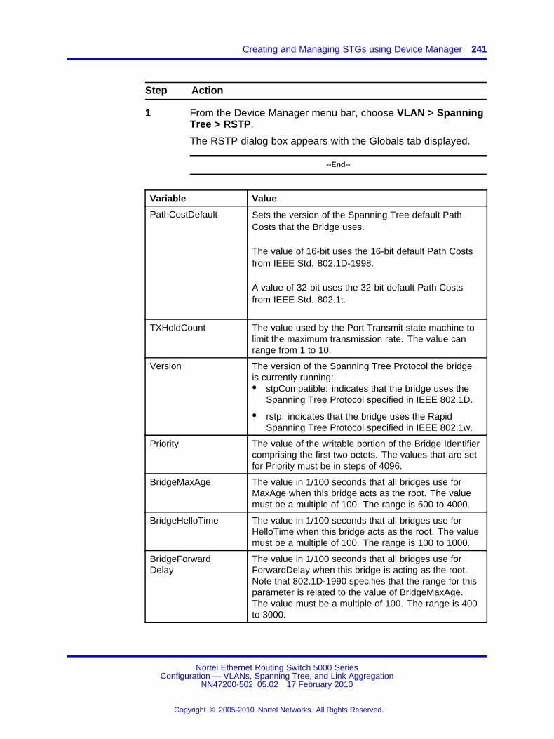
Creating and Managing STGs using Device Manager 241
Step Action
1 From the Device Manager menu bar, choose VLAN > SpanningTree > RSTP.
The RSTP dialog box appears with the Globals tab displayed.
--End--
Variable Value
PathCostDefault Sets the version of the Spanning Tree default PathCosts that the Bridge uses.
The value of 16-bit uses the 16-bit default Path Costsfrom IEEE Std. 802.1D-1998.
A value of 32-bit uses the 32-bit default Path Costsfrom IEEE Std. 802.1t.
TXHoldCount The value used by the Port Transmit state machine tolimit the maximum transmission rate. The value canrange from 1 to 10.
Version The version of the Spanning Tree Protocol the bridgeis currently running:• stpCompatible: indicates that the bridge uses the
Spanning Tree Protocol specified in IEEE 802.1D.
• rstp: indicates that the bridge uses the RapidSpanning Tree Protocol specified in IEEE 802.1w.
Priority The value of the writable portion of the Bridge Identifiercomprising the first two octets. The values that are setfor Priority must be in steps of 4096.
BridgeMaxAge The value in 1/100 seconds that all bridges use forMaxAge when this bridge acts as the root. The valuemust be a multiple of 100. The range is 600 to 4000.
BridgeHelloTime The value in 1/100 seconds that all bridges use forHelloTime when this bridge acts as the root. The valuemust be a multiple of 100. The range is 100 to 1000.
BridgeForwardDelay
The value in 1/100 seconds that all bridges use forForwardDelay when this bridge is acting as the root.Note that 802.1D-1990 specifies that the range for thisparameter is related to the value of BridgeMaxAge.The value must be a multiple of 100. The range is 400to 3000.
Nortel Ethernet Routing Switch 5000 SeriesConfiguration — VLANs, Spanning Tree, and Link Aggregation
NN47200-502 05.02 17 February 2010
Copyright © 2005-2010 Nortel Networks. All Rights Reserved.
.

242 Configuring STP using Device Manager
Variable Value
DesignatedRoot The unique identifier of the Bridge recorded as theRoot in the Configuration BPDUs that are transmittedby the Designated Bridge for the segment to whichthe port is attached. Reference IEEE 802.1D-1990:Section 4.5.5.4.
RootCost The cost of the path to the root as seen from thisbridge.
RootPort The port number of the port that offers the lowest costpath from this bridge to the root bridge.
MaxAge The maximum age of Spanning Tree Protocolinformation learned from the network on any portbefore being discarded. The maximum age is specifiedin units of hundredths of a second. This is the actualvalue that the bridge uses.
HelloTime The amount of time required for transmission of theconfiguration BPDUs by the node on any port whenit is the root of the spanning tree or trying to becomethe root. This is specified in units of hundredths of asecond. This is the actual value that the bridge uses.
ForwardDelay This time value, measured in units of hundredths of asecond, controls how fast a port changes its spanningstate when moving towards the Forwarding state. Thevalue determines how long the port stays in each ofthe Listening and Learning states, which precede theForwarding state.
RstpUpCount The number of times the RSTP Module has beenenabled. A trap is generated on the occurrence of thisevent.
RstpDownCount The number of times the RSTP Module has beendisabled. A trap is generated on the occurrence of thisevent
NewRootIdCount The number of times this Bridge has detected aRoot Identifier change. A trap is generated on theoccurrence of this event.
TimeSinceTopologyChange
The time (in hundredths of a second) since the TcWhileTimer for any port in this Bridge was non-zero for theCommon Spanning Tree context.
TopChanges The total number of topology changes detected by thisbridge since the management entity was last reset orinitialized.
RSTP Ports tabTo view the RSTP Ports tab:
Nortel Ethernet Routing Switch 5000 SeriesConfiguration — VLANs, Spanning Tree, and Link Aggregation
NN47200-502 05.02 17 February 2010
Copyright © 2005-2010 Nortel Networks. All Rights Reserved.
.

Creating and Managing STGs using Device Manager 243
Step Action
1 From the Device Manager menu bar, choose VLAN > SpanningTree > RSTP.
The RSTP dialog box appears with the Globals tab displayed.
2 Click the RSTP Ports tab.
The RSTP Ports tab appears.
--End--
Variable Value
Port The port number.
State Used to identify a port state in this RSTP instance.The port state is cataloged as discarding, learning,and forwarding.
Priority The value of the priority field which is contained inthe first (in network byte order) octet of the (2 octetlong) Port ID.
PathCost The contribution of this port to the cost of pathstowards the spanning tree root.
ProtocolMigration Indicates the Protocol migration state of this port.Set this field to true to force the port to transmitRSTP BPDUs. Note: If this field is set to true andthe port receives an 802.1d type BPDU, the portagain begins transmitting 802.1d BPDUs.
AdminEdgePort The administrative value of the Edge Portparameter. A value of true indicates that this portis assumed to be an edge-port and a value offalse indicates that this port is assumed to be anonedge-port.
OperEdgePort The operational value of the Edge Port parameter.The object is initialized to false on reception of aBPDU.
Nortel Ethernet Routing Switch 5000 SeriesConfiguration — VLANs, Spanning Tree, and Link Aggregation
NN47200-502 05.02 17 February 2010
Copyright © 2005-2010 Nortel Networks. All Rights Reserved.
.

244 Configuring STP using Device Manager
Variable Value
AdminPointToPoint The administrative point-to-point status of the LANsegment attached to this port.
• A value of forceTrue indicates that this portis always treated as being connected to apoint-to-point link.
• A value of forceFalse indicates that this port istreated as having a shared media connection.
• A value of auto indicates that this port isconsidered to have a point-to-point link if itis an aggregator and all of its members areaggregatable, or if the MAC entity is configuredfor full duplex operation, either throughauto-negotiation or by management means.
OperPointToPoint The operational point-to-point status of theLAN segment attached to this port. This fieldindicates whether a port is considered to have apoint-to-point connection. The value is determinedby management or by auto-detection.
Participating This field specifies whether a port is participating inthe 802.1w protocol.
DesignatedRoot The bridge identifier of the old root of the SpanningTree as determined by the Spanning Tree Protocolas executed by this node.
DesignatedCost The path cost of the Designated Port of thesegment connected to this port. This value iscompared to the Root Path Cost field in receivedBPDUs.
DesignatedBridge The Bridge Identifier of the bridge which this portconsiders to be the Designated Bridge for this portsegment.
DesignatedPort The Port Identifier for the port segment which is onthe Designated Bridge.
ForwardTransitions The number of times this port has transitioned fromthe Learning state to the Forwarding state.
RSTP Status tabTo view the RSTP Status tab:
Step Action
1 From the Device Manager menu bar, choose VLAN > SpanningTree > RSTP.
Nortel Ethernet Routing Switch 5000 SeriesConfiguration — VLANs, Spanning Tree, and Link Aggregation
NN47200-502 05.02 17 February 2010
Copyright © 2005-2010 Nortel Networks. All Rights Reserved.
.

Creating and Managing STGs using Device Manager 245
The RSTP dialog box appears with the Globals tab displayed.
2 Click the RSTP Status tab.
The RSTP Status tab appears.
--End--
Variable Value
Port The port number.
Role A role represents a functionality characteristicor capability of a resource to which policies areapplied.
OperVersion This indicates whether the Port is operationallyin the RSTP mode or the STP-compatiblemode; that is, whether the Port is transmittingRSTP BPDUs or Config/TCN BPDUs.
EffectivePortState This is the effective Operational state of theport. This object is set to true only whenthe port is operationally up in the interfacemanager and when the force Port State andspecified port state for this port is enabled.Otherwise, this object is set to false.
Graphing RSTP Port StatisticsYou can use the RSTP Stats tab to graph RSTP port statistics.
To open the RSTP Stats tab for graphing:
Step Action
1 From the Device Manager menu bar, choose VLAN > SpanningTree > RSTP.
The RSTP dialog box appears with the Globals tab displayed.
2 Click the RSTP Status tab.
3 Select a port and click Graph to get the statistics for the RSTPPort.
The RSTP Stats tab appears.
--End--
Nortel Ethernet Routing Switch 5000 SeriesConfiguration — VLANs, Spanning Tree, and Link Aggregation
NN47200-502 05.02 17 February 2010
Copyright © 2005-2010 Nortel Networks. All Rights Reserved.
.

246 Configuring STP using Device Manager
Variable Value
RxRstBpduCount The number of RST BPDUs that havebeen received on the port.
RxConfigBpduCount The number of Config BPDUs that havebeen received on the port.
RxTcnBpduCount The number of TCN BPDUs that havebeen received on the port.
TxRstBpduCount The number of RST BPDUs that havebeen transmitted by this port.
TxConfigBpduCount The number of Config BPDUs that havebeen transmitted by this port.
TxTcnBpduCount The number of TCN BPDUs that havebeen transmitted by this port.
InvalidRstBpduRxCount The number of invalid RSTP BPDUs thathave been received on this port.
InvalidConfigBpduRxCount The number of invalid ConfigurationBPDUs that have been received on thisport.
InvalidTcnBpduRxCount The number of invalid TCN BPDUs thathave been received on this port.
ProtocolMigrationCount The number of times this Port hasmigrated from one STP protocol versionto another. The relevant protocols areSTP-COMPATIBLE and RSTP.
Configuring MSTP using Device ManagerWith the Multiple Spanning Tree Protocol (MSTP or IEEE 802.1s), you canconfigure multiple instances of RSTP on the same switch. Each MSTPinstance can include one or more VLANs. The operation of the MSTP issimilar to the current Nortel proprietary STG.
In the MSTP mode, the 5000 Series switches support a maximum of oneCommon and Internal Spanning Tree (CIST) and seven Multiple SpanningTree Instances (MSTI).
Within the CIST, the Internal Spanning Tree component is used only bydevices from the same region (for which a regional root is elected). TheCommon (External) Spanning Tree component of the CIST is used bydevices from different regions or between devices with different STPmodes.
Note: The MSTP dialog boxes and tabs described in this section areaccessible only when the STP mode is set to MSTP.
Nortel Ethernet Routing Switch 5000 SeriesConfiguration — VLANs, Spanning Tree, and Link Aggregation
NN47200-502 05.02 17 February 2010
Copyright © 2005-2010 Nortel Networks. All Rights Reserved.
.
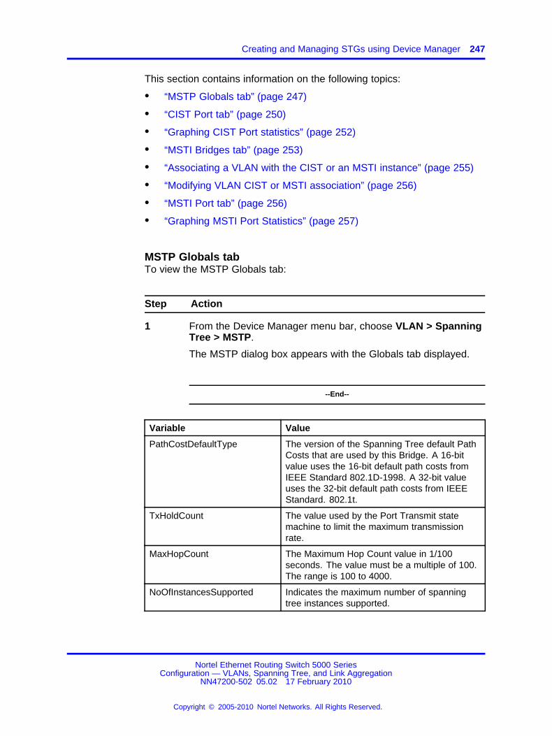
Creating and Managing STGs using Device Manager 247
This section contains information on the following topics:
• “MSTP Globals tab” (page 247)
• “CIST Port tab” (page 250)
• “Graphing CIST Port statistics” (page 252)
• “MSTI Bridges tab” (page 253)
• “Associating a VLAN with the CIST or an MSTI instance” (page 255)
• “Modifying VLAN CIST or MSTI association” (page 256)
• “MSTI Port tab” (page 256)
• “Graphing MSTI Port Statistics” (page 257)
MSTP Globals tabTo view the MSTP Globals tab:
Step Action
1 From the Device Manager menu bar, choose VLAN > SpanningTree > MSTP.
The MSTP dialog box appears with the Globals tab displayed.
--End--
Variable Value
PathCostDefaultType The version of the Spanning Tree default PathCosts that are used by this Bridge. A 16-bitvalue uses the 16-bit default path costs fromIEEE Standard 802.1D-1998. A 32-bit valueuses the 32-bit default path costs from IEEEStandard. 802.1t.
TxHoldCount The value used by the Port Transmit statemachine to limit the maximum transmissionrate.
MaxHopCount The Maximum Hop Count value in 1/100seconds. The value must be a multiple of 100.The range is 100 to 4000.
NoOfInstancesSupported Indicates the maximum number of spanningtree instances supported.
Nortel Ethernet Routing Switch 5000 SeriesConfiguration — VLANs, Spanning Tree, and Link Aggregation
NN47200-502 05.02 17 February 2010
Copyright © 2005-2010 Nortel Networks. All Rights Reserved.
.

248 Configuring STP using Device Manager
Variable Value
MstpUpCount The number of times the MSTP Moduleis enabled. A trap is generated on theoccurrence of this event.
MstpDownCount The number of times the MSTP Moduleis disabled. A trap is generated on theoccurrence of this event.
ForceProtocolVersion Signifies the version of the Spanning TreeProtocol that the bridge is currently running.• stpCompatible indicates that the bridge
is using the Spanning Tree Protocol asspecified in IEEE 802.1D.
• rstp indicates that the bridge is using theRapid Spanning Tree Protocol as specifiedin IEEE 802.1w.
• mstp indicates that the bridge is runningthe Multiple Spanning Tree Protocol asspecified in IEEE 802.1s.
BrgAddress The bridge address is generated when eventslike protocol up or protocol down occurs.
Root The bridge identifier of the root of the commonspanning tree as determined by the SpanningTree Protocol as executed by this node. Thisvalue is used as the CIST Root Identifierparameter in all Configuration BPDUsoriginated by this node.
RegionalRoot The bridge identifier of the root of the MultipleSpanning Tree region as determined by theSpanning Tree Protocol as executed by thisnode. This value is used as the CIST RegionalRoot Identifier parameter in all ConfigurationBridge PDUs originated by this node.
RootCost The cost of the path to the CIST Root as seenfrom this bridge.
RegionalRootCost The cost of the path to the CIST Regional Rootas seen from this bridge.
RootPort The port number of the port which offers thelowest path cost from the bridge to the CISTRoot Bridge
BridgePriority The value of the writable portion of the BridgeIdentifier comprising the first two octets. Thevalues that are set for Bridge Priority must bein steps of 4096.
Nortel Ethernet Routing Switch 5000 SeriesConfiguration — VLANs, Spanning Tree, and Link Aggregation
NN47200-502 05.02 17 February 2010
Copyright © 2005-2010 Nortel Networks. All Rights Reserved.
.

Creating and Managing STGs using Device Manager 249
Variable Value
BridgeMaxAge The value in hundredths of a second that allbridges use for MaxAge when this bridge actsas the root. The value must be a multiple of100. The range is 600 to 4000.
BridgeForwardDelay The value in hundredths of a second that allbridges use for ForwardDelay when this bridgeacts as the root. IEEE 802.1D specifies thatthe range for this parameter is related to thevalue of BridgeMaxAge. The value must be amultiple of 100. The range is 400 to 3000.
HoldTime This value determines the time interval duringwhich no more than two Configuration BPDUscan be transmitted by this node. This value ismeasured in units of hundredths of a second.
MaxAge The maximum age, in hundredths of a second,of the Spanning Tree Protocol informationlearned from the network on any port beforebeing discarded. This value is the actual valuethat this bridge is currently using.
ForwardDelay This value controls how fast a port changesits STP state when moving towards theForwarding state. This value determineshow long the port stays in a particular statebefore moving to the next state. This value ismeasured in units of hundredths of a second.
TimeSinceTopologyChange
The time, in hundredths of a second, sincethe TcWhile Timer for any port in this Bridgewas non-zero for the Common Spanning Treecontext.
NewRootBridgeCount The number of times this Bridge detects aRoot Bridge change for the Common SpanningTree context. A Trap is generated when thisevent occurs.
TopChanges The number of times that at least one non-zeroTcWhile Timer occurred on this Bridge for theCommon Spanning Tree context.
RegionName Specifies the region name of the configuration.By default, the Region Name is equal to theBridge Mac Address.
ConfigIdSel The Configuration Identifier Format Selectorused by the Bridge. This has a fixed value of 0which indicates RegionName, RegionVersion,as specified in the standard.
RegionVersion Denotes the version of the MST Region.
Nortel Ethernet Routing Switch 5000 SeriesConfiguration — VLANs, Spanning Tree, and Link Aggregation
NN47200-502 05.02 17 February 2010
Copyright © 2005-2010 Nortel Networks. All Rights Reserved.
.

250 Configuring STP using Device Manager
Variable Value
ConfigDigest Signifies the Configuration Digest value forthis Region. This is an MD5 digest value andhence must always be 16 octets long.
RegionConfigChangeCount
The number of times a Region ConfigurationIdentifier Change is detected. A trap isgenerated when this event occurs.
CIST Port tabTo view the CIST Port tab:
Step Action
1 From the Device Manager menu bar, choose VLAN > SpanningTree > MSTP.
The MSTP dialog box appears with the Globals tab displayed.
2 Click the CIST Port tab.
The CIST Port tab appears.
--End--
Variable Value
Port The port number of the port containingSpanning Tree information.
PathCost The contribution of this port to the cost of pathstowards the CIST Root.
Priority The four most significant bits of the PortIdentifier of the Spanning Tree instance. Itcan be modified by setting the CistPortPriorityvalue. The values that are set for Port Prioritymust be in steps of 16.
DesignatedRoot This field specifies the unique Bridge Identifierof the bridge. Recorded as the CIST Rootin the configuration BPDUs which aretransmitted.
DesignatedCost The path cost of the Designated Port of thesegment connected to this port.
DesignatedBridge The unique Bridge Identifier of the bridgewhich the port considers to be the DesignatedBridge for the port segment.
Nortel Ethernet Routing Switch 5000 SeriesConfiguration — VLANs, Spanning Tree, and Link Aggregation
NN47200-502 05.02 17 February 2010
Copyright © 2005-2010 Nortel Networks. All Rights Reserved.
.

Creating and Managing STGs using Device Manager 251
Variable Value
DesignatedPort The Port identifier of the port on theDesignated Bridge which is designated for theport segment.
RegionalRoot Displays the unique Bridge Identifier of thebridge. Recorded as the CIST Regional RootIdentifier in the configuration BPDUs which aretransmitted.
RegionalPathCost The contribution of this port to the cost of pathstowards the CIST Regional Root.
ProtocolMigration Indicates the Protocol migration state of thisport. When operating in MSTP mode, set thisfield to true to force the port to transmit MSTPBPDUs without instance information.Note: If this field is set to true and the portreceives an 802.1d BPDU, the port beginstransmitting 802.1d BPDUs. If the port receivesan 802.1w BPDU, it begins transmitting 802.1wBPDUs.
AdminEdgeStatus The administrative value of the Edge Portparameter. A value of true indicates that thisport can be assumed to be an edge-port, anda value of false indicates that this port can beassumed to be a nonedge-port.
OperEdgeStatus Signifies the operational value of the Edge Portparameter. This value is initialized to the valueof AdminEdgeStatus and set to false when theport receives a BPDU.
AdminP2P The administrative point-to-point status of theLAN segment attached to this port. A valueof 0 indicates that this port is always treatedas being connected to a point-to-point link. Avalue of 1 indicates that this port is treated ashaving a shared media connection. A valueof 2 indicates that this port is considered tohave a point-to-point link if it is an Aggregatorand all of its members are aggregatable, orif the MAC entity is configured for full duplexoperation, either through auto-negotiation, orby management means.
OperP2P This field indicates the operationalpoint-to-point status of the LAN segmentattached to the port. It also indicates whethera port is considered to have a point-to-pointconnection. The value is determined bymanagement or by auto-detection, asdescribed in the AdminP2P object.
Nortel Ethernet Routing Switch 5000 SeriesConfiguration — VLANs, Spanning Tree, and Link Aggregation
NN47200-502 05.02 17 February 2010
Copyright © 2005-2010 Nortel Networks. All Rights Reserved.
.

252 Configuring STP using Device Manager
Variable Value
HelloTime The amount of time between the transmissionof Configuration BPDUs transmitted bythis node on the port. Measured in units ofhundredths of a second.
OperVersion This indicates whether the Port is operationallyin the MSTP, RSTP, or STP-compatible mode;that is, whether the port is transmitting MSTBPDUs, RST BPDUs, or Config/TCN BPDUs.
EffectivePortState The effective operational state of the port forCIST. This is set to true only when the portis operationally up in the Interface level andProtocol level for CIST. This is set to false forall other times.
State The current state of the port as defined by theCommon Spanning Tree Protocol.
ForcePortState The current state of the port which can bechanged to either Disabled or Enabled for thebase Spanning Tree instance.
SelectedPortRole Selected port role for the Spanning Treeinstance.
CurrentPortRole Current port role for the Spanning Treeinstance.
Graphing CIST Port statisticsThe CIST Port Stats tab shows CIST Port statistics.
To open the CIST Port Stats tab for graphing:
Step Action
1 From the Device Manager menu bar, choose VLAN > SpanningTree > MSTP.
The MSTP dialog box appears with the Globals tab displayed.
2 Click the CIST Port tab.
The CIST Port tab appears.
3 Select a port and click Graph to get the statistics for the CISTPort.
The following table describes the fields that are displayed in theCIST Port Stats tab.
--End--
Nortel Ethernet Routing Switch 5000 SeriesConfiguration — VLANs, Spanning Tree, and Link Aggregation
NN47200-502 05.02 17 February 2010
Copyright © 2005-2010 Nortel Networks. All Rights Reserved.
.

Creating and Managing STGs using Device Manager 253
Variable Value
ForwardTransitions The number of times this port transitioned tothe Forwarding State.
RxMstBpduCount The number of MST BPDUs received on thisport.
RxRstBpduCount The number of RST BPDUs received on thisport.
RxConfigBpduCount The number of Configuration BPDUs receivedon this port.
RxTcnBpduCount The number of TCN BPDUs received on thisport.
TxMstBpduCount The number of MST BPDUs transmitted fromthis port.
TxRstBpduCount The number of RST BPDUs transmitted fromthis port.
TxConfigBpduCount The number of Configuration BPDUstransmitted from this port.
TxTcnBpduCount The number of TCN BPDUs transmitted fromthis port.
InvalidMstBpduRxCount The number of Invalid MST BPDUs receivedon this port.
InvalidRstBpduRxCount The number of Invalid RST BPDUs receivedon this port.
InvalidConfigBpduRxCount
The number of Invalid Configuration BPDUsreceived on this port.
InvalidTcnBpduRxCount The number of Invalid TCN BPDUs receivedon this port.
ProtocolMigrationCount The number of times this port migratedfrom one STP protocol version to another.The relevant migration protocols areSTP-COMPATIBLE and RSTP/MSTP. A trap isgenerated when the port migrates.
MSTI Bridges tabTo view the MSTI Bridges tab:
Step Action
1 From the Device Manager menu bar, choose VLAN > SpanningTree > MSTP.
The MSTP dialog box appears with the Globals tab displayed.
2 Click the MSTI Bridges tab.
Nortel Ethernet Routing Switch 5000 SeriesConfiguration — VLANs, Spanning Tree, and Link Aggregation
NN47200-502 05.02 17 February 2010
Copyright © 2005-2010 Nortel Networks. All Rights Reserved.
.

254 Configuring STP using Device Manager
The MSTI Bridges tab appears.
--End--
Variable Value
Instance Spanning Tree Instance to which theinformation belongs.
RegionalRoot Indicates the MSTI Regional Root Identifiervalue for the Instance. This value is used asthe MSTI Regional Root Identifier parameterin all Configuration Bridge PDUs originated bythis node.
Priority The writable portion of the MSTI BridgeIdentifier comprising the first two octets. Thevalues that are set for Bridge Priority must bein steps of 4096.
RootCost The cost of the path to the MSTI RegionalRoot as seen by this bridge.
RootPort The number of the port which offers the lowestpath cost from this bridge to the MSTI RegionRoot Bridge.
Enabled Used to control whether the bridge instance isenabled or disabled.
TimeSinceTopologyChange
The time (measured in hundredths of asecond) since the TcWhile Timer for any portin this Bridge was non-zero for this SpanningTree instance.
TopChanges The number of times that at least one non-zeroTcWhile Timer occurred on this Bridge for thisSpanning Tree instance.
NewRootCount The number of times this Bridge has detecteda Root Bridge change for this SpanningTree instance. A Trap is generated on theoccurrence of this event.
InstanceUpCount The number of times a new Spanning Treeinstance was created. A Trap is generated onthe occurrence of this event.
InstanceDownCount The number of times a Spanning Tree instancewas deleted. A Trap is generated on theoccurrence of this event.
To insert an MSTI bridge:
Nortel Ethernet Routing Switch 5000 SeriesConfiguration — VLANs, Spanning Tree, and Link Aggregation
NN47200-502 05.02 17 February 2010
Copyright © 2005-2010 Nortel Networks. All Rights Reserved.
.

Creating and Managing STGs using Device Manager 255
Step Action
1 From the Device Manager menu bar, choose VLAN > SpanningTree > MSTP.
The MSTP dialog box appears with the Globals tab displayed.
2 Click the MSTI Bridges tab.
The MSTI Bridges tab appears.
3 In the MSTI Bridges tab, click the Insert button.
The Instance dialog box appears with the next available instanceshown.
4 Click Insert.
The next available instance appears in the MSTI Bridges tab.
--End--
Step Action
1 From the Device Manager menu bar, choose VLAN > SpanningTree > MSTP.
The MSTP dialog box appears with the Globals tab displayed.
2 Click the MSTI Bridges tab.
The MSTI Bridges tab appears.
3 In the MSTI Bridges tab, click the Instance field for the MSTIbridge that you want to delete.
4 Click Delete.
The selected instance is deleted from the MSTI Bridges tab.
--End--
Associating a VLAN with the CIST or an MSTI instanceYou can use Device Manager to associate a VLAN with the CIST or anMSTI instance. To associate a VLAN with the CIST or an MSTI instance:
Step Action
1 From the Device Manager menu bar, choose VLAN > VLANs.
The VLAN dialog box appears with the Basic tab displayed.
2 Click Insert.
Nortel Ethernet Routing Switch 5000 SeriesConfiguration — VLANs, Spanning Tree, and Link Aggregation
NN47200-502 05.02 17 February 2010
Copyright © 2005-2010 Nortel Networks. All Rights Reserved.
.

256 Configuring STP using Device Manager
The VLAN, Insert Basic dialog box appears.
3 In the MstpInstance field, select the CIST or an MSTI instancefrom the menu.
4 Populate the other fields as required.
5 Click Insert.
--End--
Modifying VLAN CIST or MSTI associationTo modify an existing VLAN association with a CIST or MSTI:
Step Action
1 From the VLAN Basic tab, double-click in the MstpInstancefield.
The MstpInstance menu appears.
2 Select the CIST option or one of the MSTI options and clickApply.
This associates the VLAN with the option you selected.
--End--
MSTI Port tabTo view the MSTI Port tab:
Step Action
1 From the Device Manager menu bar, choose VLAN > SpanningTree > MSTP.
The MSTP dialog box appears with the Globals tab displayed.
2 Click the MSTI Port tab.
The MSTI Port tab appears.
--End--
Variable Value
Port Denotes the port number.
Nortel Ethernet Routing Switch 5000 SeriesConfiguration — VLANs, Spanning Tree, and Link Aggregation
NN47200-502 05.02 17 February 2010
Copyright © 2005-2010 Nortel Networks. All Rights Reserved.
.

Creating and Managing STGs using Device Manager 257
Variable Value
BridgeInstance The number of times a Spanning Tree instancewas deleted. A Trap is generated when thisevent occurs.
State Indicates the current state of the port asdefined by the Multiple Spanning TreeProtocol. The state of a port can beForwarding or Discarding (Blocking).
ForcePortState Signifies the current state of the port which canbe changed to either Disabled or Enabled forthe specific Spanning Tree instance.
PathCost The contribution of this port to the cost of pathstowards the MSTI Root which includes thisport.
Priority Indicates the four most significant bits ofthe Port Identifier for a given SpanningTree instance. This value can be modifiedindependently for each Spanning Treeinstance supported by the Bridge. The valuesset for Port Priority must be in steps of 16.
DesignatedRoot The unique Bridge Identifier of the bridgerecorded as the MSTI Regional Root in theconfiguration BPDUs that are transmitted.
DesignatedBridge The unique Bridge Identifier of the bridgewhich this port considers to be the DesignatedBridge for the port segment.
DesignatedPort The Port identifier of the port on theDesignated Bridge for this port segment.
DesignatedCost The path cost of the Designated Port of thesegment connected to this port.
CurrentPortRole Current Port Role of the port for this spanningtree instance.
EffectivePortState The effective operational state of the portfor the specific instance. This is set to trueonly when the port is operationally up inthe interface level and Protocol level for thespecific instance. This is set to false at allother times.
Graphing MSTI Port StatisticsThe MSTI Port tab can be used to graph MSTI port statistics.
To open the MSTI Port tab for graphing:
Nortel Ethernet Routing Switch 5000 SeriesConfiguration — VLANs, Spanning Tree, and Link Aggregation
NN47200-502 05.02 17 February 2010
Copyright © 2005-2010 Nortel Networks. All Rights Reserved.
.

258 Configuring STP using Device Manager
Step Action
1 From the Device Manager menu bar, choose VLAN > SpanningTree > MSTP.
The MSTP dialog box appears with the Globals tab displayed.
2 Click the MSTI Port tab.
3 Select a port and click Graph to get the statistics for the MSTIPort.
The following table describes the fields in the MSTI PortStatistics fields.
--End--
Variable Value
ForwardTransitions Number of times this port transitioned to theForwarding State for the specific instance.
ReceivedBPDUs Number of BPDUs received by this port for thisspanning tree instance.
TransmittedBPDUs Number of Invalid BPDUs received on this Portfor this Spanning Tree instance.
InvalidBPDUsRcvd Number of BPDUs transmitted on this port forthis Spanning Tree instance.
Nortel Ethernet Routing Switch 5000 SeriesConfiguration — VLANs, Spanning Tree, and Link Aggregation
NN47200-502 05.02 17 February 2010
Copyright © 2005-2010 Nortel Networks. All Rights Reserved.
.
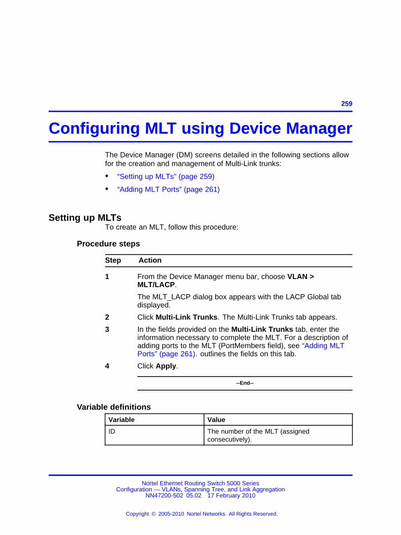
259.
Configuring MLT using Device ManagerThe Device Manager (DM) screens detailed in the following sections allowfor the creation and management of Multi-Link trunks:
• “Setting up MLTs” (page 259)
• “Adding MLT Ports” (page 261)
Setting up MLTsTo create an MLT, follow this procedure:
Procedure steps
Step Action
1 From the Device Manager menu bar, choose VLAN >MLT/LACP.
The MLT_LACP dialog box appears with the LACP Global tabdisplayed.
2 Click Multi-Link Trunks. The Multi-Link Trunks tab appears.
3 In the fields provided on the Multi-Link Trunks tab, enter theinformation necessary to complete the MLT. For a description ofadding ports to the MLT (PortMembers field), see “Adding MLTPorts” (page 261). outlines the fields on this tab.
4 Click Apply.
--End--
Variable definitions
Variable Value
ID The number of the MLT (assignedconsecutively).
Nortel Ethernet Routing Switch 5000 SeriesConfiguration — VLANs, Spanning Tree, and Link Aggregation
NN47200-502 05.02 17 February 2010
Copyright © 2005-2010 Nortel Networks. All Rights Reserved.
.

260 Configuring MLT using Device Manager
Variable Value
PortType The port type:• Access
• trunk
• UntagPvidOnly
• TagPvidOnly
Name The name given to the MLT.
PortMembers The ports that are assigned to the MLT.
VlanIds Specifies the VLAN identifier.
Loadbalance(Mode) Sets the MLT load balancing mode aseither basic (MAC-based load balancing) oradvanced (IP-based load balancing).
Enable Specifies whether the Multi-Link trunk is active.
MltType Editable field that specifies the type of MLT:• normalMLT
• istMLT
• splitMLT
RunningType Read-only field the displays the current MLToperational type:• normalMLT
• istMLT
• splitMLT
SmltId The assigned SMLT ID. Both ends of theSMLT must have the same SMLT ID. TheSmltId field is used when the MltType issplitMLT. The SmltId value should be 0 if theMltType is not splitMLT.
Filtering the Multi-Link Trunks tab displayTo filter the display of the Multi-Link Trunks tab to display selected typesof MLT.
Procedure steps
Step Action
1 From the Multi-Link Trunks tab, click Filter.
The MLT_LACP, Multi-Link Trunks - Filter dialog box appears.
2 Set the properties, and click Filter.
Nortel Ethernet Routing Switch 5000 SeriesConfiguration — VLANs, Spanning Tree, and Link Aggregation
NN47200-502 05.02 17 February 2010
Copyright © 2005-2010 Nortel Networks. All Rights Reserved.
.

Configuring SMLT using Device Manager 261
The Multi-Link Trunks table displays information based on thespecified criteria.
--End--
Adding MLT PortsTo add ports to an MLT, follow this procedure:
The selected ports are now displayed on the MLT_LACP dialog box in thePortMembers field.
Procedure steps
Step Action
1 From the Device Manager menu bar, choose VLAN >MLT/LACP. The MLT_LACP dialog box appears with the LACPGlobal tab displayed.
2 Click Multi-Link Trunks.
The Multi-Link Trunks tab appears.
3 Double-click in the PortMembers field for the MLT to which portsare to be added. The PortMembers screen appears.
4 Click on the buttons that represent the ports that are to be addedto the MLT. For the 5000 Series, up to 8 same-type ports canbelong to a single MLT
5 Click OK.
6 Click Apply.
--End--
Configuring SMLT using Device ManagerThis section describes how to use Device Manager (DM) to configure SplitMulti-Link Trunking (SMLT) and includes the following topics:
• “Adding an MLT-based SMLT” (page 262)
• “Viewing SLTs configured on your switch” (page 263)
• “Configuring an IST MLT” (page 264)
• “Removing an IST MLT” (page 265)
• “Viewing IST statistics” (page 265)
• “Configuring an SLT” (page 268)
Nortel Ethernet Routing Switch 5000 SeriesConfiguration — VLANs, Spanning Tree, and Link Aggregation
NN47200-502 05.02 17 February 2010
Copyright © 2005-2010 Nortel Networks. All Rights Reserved.
.

262 Configuring MLT using Device Manager
• “Deleting an SLT” (page 269)
• “Troubleshooting IST problems” (page 190)
Note: To configure SMLT on the 5000 Series switch, an AdvancedLicense must be purchased that allows this feature to be used.
Adding an MLT-based SMLT
ATTENTIONFor SMLT to function properly, you must manually disable STP on all SMLT,IST, and SLT ports in all spanning tree groups or instances to which the portsbelong. You must also disable STP on all edge switch MLT ports that areconnected to the SMLT or SLT.
You can create an SMLT from the Multi-Link Trunks tab by selecting theMLT type as SMLT and then specifying an SMLT ID.
To add an MLT-based SMLT:
Procedure steps
Step Action
1 From the Device Manager menu bar, choose VLAN >MLT/LACP.
The MLT_LACP dialog box appears with the LACP Global tabdisplayed.
2 Select the Multi-Link Trunks tab.
The Multi-Link Trunks tab appears.
3 From the displayed list of MLTs, choose an available MLT toconfigure as an SMLT.
4 In the row containing the desired MLT, double-click thePortMembers field.
The PortMembers dialog box appears, displaying the availableports.
5 Click the ports to include in the MLT-based SMLT.
For the 5000 Series, up to eight same-type ports can belong toa single MLT.
6 Click OK.
The MltPortMembers dialog box closes, and the ports are addedto the PortMembers field.
7 Double-click the MltType field and choose splitMLT from the list.
Nortel Ethernet Routing Switch 5000 SeriesConfiguration — VLANs, Spanning Tree, and Link Aggregation
NN47200-502 05.02 17 February 2010
Copyright © 2005-2010 Nortel Networks. All Rights Reserved.
.

Configuring SMLT using Device Manager 263
8 In the SmltId field, type an unused SMLT ID (1 - 32).
Note: The corresponding SMLTs between aggregationswitches must have matching SMLT IDs. The same IDnumber must be used on both sides.
9 Click Apply.
--End--
Viewing SLTs configured on your switchTo view the SLTs configured on your switch:
Procedure steps
Step Action
1 From the Device Manager menu bar, choose VLAN >MLT/LACP.
The MLT_LACP dialog box appears with the LACP Global tabdisplayed.
2 Select the Single Port SMLT tab.
The Single Port SMLT tab appears.
--End--
Variable definitions
Variable Value
Index Displays the index number.
SmltId The ID number of the SLT (1 - 512).
RunningType Read only field that displays the current portoperational type:
• normal
• smlt (single port Split MLT)
Nortel Ethernet Routing Switch 5000 SeriesConfiguration — VLANs, Spanning Tree, and Link Aggregation
NN47200-502 05.02 17 February 2010
Copyright © 2005-2010 Nortel Networks. All Rights Reserved.
.

264 Configuring MLT using Device Manager
Configuring an IST MLT
ATTENTIONFor SMLT to function properly, you must manually disable STP on all SMLT,IST, and SLT ports in all spanning tree groups or instances to which the portsbelong. You must also disable STP on all edge switch MLT ports that areconnected to the SMLT or SLT.
To configure an IST MLT:
Procedure steps
Step Action
1 From the Device Manager menu bar, choose VLAN >MLT/LACP.
The MLT_LACP dialog box appears with the LACP Global tabdisplayed.
2 Select the Multi-Link Trunks tab.
The Multi-Link Trunks tab appears.
3 In the row containing the desired MLT, double-click thePortMembers field.
The PortMembers dialog box appears, displaying the availableports.
4 Select the ports to include in the MLT and click OK.
For the 5000 Series, up to eight same-type ports can belong toa single MLT.
The MltPortMembers dialog box closes, and the ports are addedto the PortMembers field.
5 Double-click the Enable field and choose true.
6 Double-click the MltType field and choose istMLT from the list.
7 Click Apply.
8 Select any field in the IST MLT row and click the istMlt button.
The Ist MLT dialog box appears. For field definitions, see .
9 In the PeerIp field, enter a peer IP address.
10 In the VlanId field, enter a VLAN ID.
11 In the SessionEnable field, click enable.
12 Click Apply.
Nortel Ethernet Routing Switch 5000 SeriesConfiguration — VLANs, Spanning Tree, and Link Aggregation
NN47200-502 05.02 17 February 2010
Copyright © 2005-2010 Nortel Networks. All Rights Reserved.
.
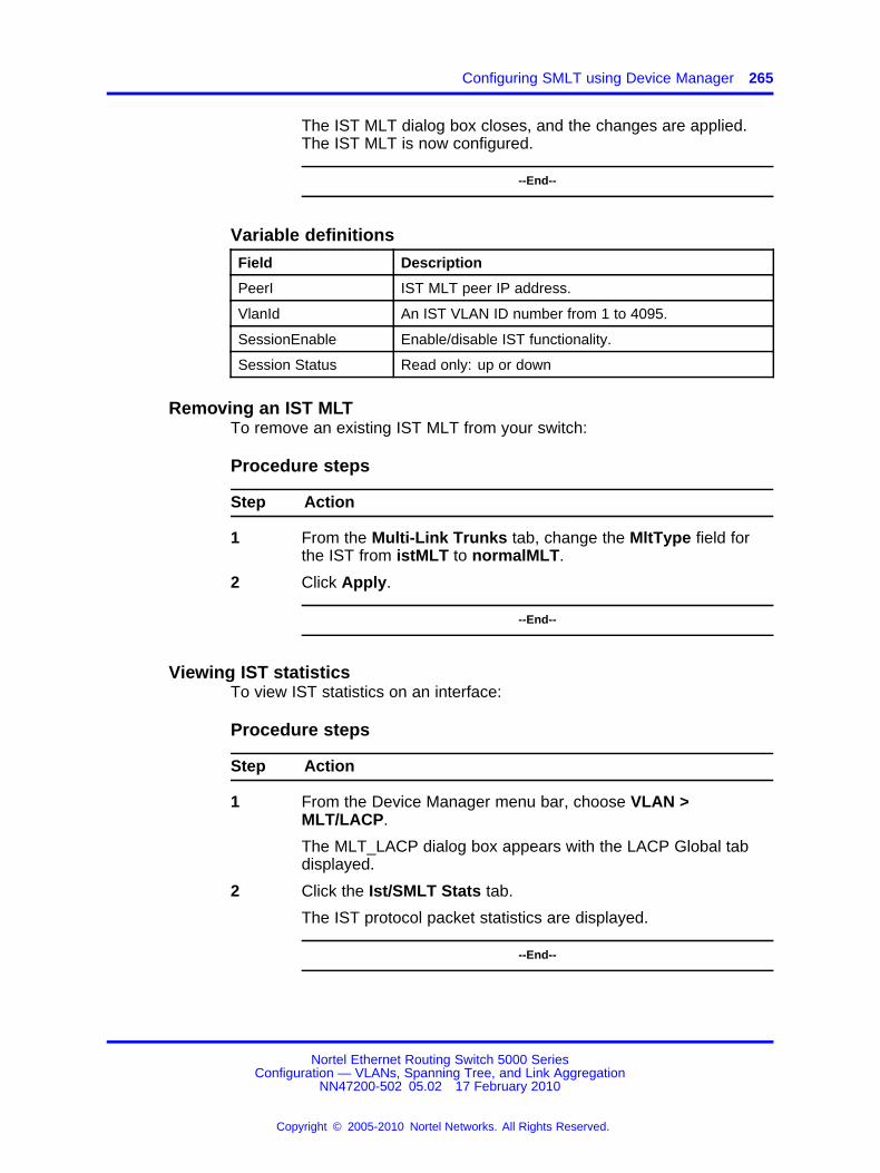
Configuring SMLT using Device Manager 265
The IST MLT dialog box closes, and the changes are applied.The IST MLT is now configured.
--End--
Variable definitions
Field Description
PeerI IST MLT peer IP address.
VlanId An IST VLAN ID number from 1 to 4095.
SessionEnable Enable/disable IST functionality.
Session Status Read only: up or down
Removing an IST MLTTo remove an existing IST MLT from your switch:
Procedure steps
Step Action
1 From the Multi-Link Trunks tab, change the MltType field forthe IST from istMLT to normalMLT.
2 Click Apply.
--End--
Viewing IST statisticsTo view IST statistics on an interface:
Procedure steps
Step Action
1 From the Device Manager menu bar, choose VLAN >MLT/LACP.
The MLT_LACP dialog box appears with the LACP Global tabdisplayed.
2 Click the Ist/SMLT Stats tab.
The IST protocol packet statistics are displayed.
--End--
Nortel Ethernet Routing Switch 5000 SeriesConfiguration — VLANs, Spanning Tree, and Link Aggregation
NN47200-502 05.02 17 February 2010
Copyright © 2005-2010 Nortel Networks. All Rights Reserved.
.

266 Configuring MLT using Device Manager
Variable definitions
Variable Value
SmltIstDownCnt The number of IST down messages.
SmltHelloTxMsgCnt The number of hello messages transmitted.
SmltHelloRxMsgCnt The number of hello messages received.
SmltLearnMacAddrTxMsgCnt The number of learn MAC address messagestransmitted.
SmltLearnMacAddrRxMsgCnt
The number of learn MAC address messagesreceived.
SmltMacAddrAgeOutTxMsgCnt
The number of MAC address aging outmessages transmitted.
SmltMacAddrAgeOutRxMsgCnt
The number of MAC address aging outmessages received.
SmltMacAddrAgeExpTxMsgCnt
The number of MAC address age expiredmessages transmitted.
SmltMacAddrAgeExpRxMsgCnt
The number of MAC address age expiredmessages received.
SmltStgInfoTxMsgCnt The number of SMLT STG info messagestransmitted.
SmltStgInfoRxMsgCnt The number of SMLT STG info messagesreceived.
SmltDelMacAddrTxMsgCnt The number of deleted MAC address messagestransmitted.
SmltDelMacAddrRxMsgCnt The number of deleted MAC address messagesreceived.
SmltSmltDownTxMsgCnt The number of SMLT down messagestransmitted.
SmltSmltDownRxMsgCnt The number of SMLT down messages received.
SmltSmltUpTxMsgCnt The number of SMLT up messages transmitted.
SmltSmltUpRxMsgCnt The number of SMLT up messages received.
SmltSendMacTblTxMsgCnt The number of send MAC table messagestransmitted.
SmltSendMacTblRxMsgCnt The number of send MAC table messagesreceived.
SmltIgmpTxMsgCnt The number of IGMP messages transmitted.
SmltIgmpRxMsgCnt The number of IGMP messages received.
SmltPortDownTxMsgCnt The number of port down messagestransmitted.
SmltPortDownRxMsgCnt The number of port down messages received.
Nortel Ethernet Routing Switch 5000 SeriesConfiguration — VLANs, Spanning Tree, and Link Aggregation
NN47200-502 05.02 17 February 2010
Copyright © 2005-2010 Nortel Networks. All Rights Reserved.
.

Configuring SMLT using Device Manager 267
Variable Value
SmltReqMacTblTxMsgCnt The number of request MAC table messagestransmitted.
SmltReqMacTblRxMsgCnt The number of request MAC table messagesreceived.
SmltRxUnknownMsgTypeCnt The number unknown SMLT messagesreceived.
Graphing MLT interface statisticsUse the following procedure to graph MLT statistics.
Procedure steps
Step Action
1 From the Device Manager menu bar, choose VLAN >MLT/LACP.
The MLT_LACP dialog box appears with the LACP Global tabdisplayed.
2 Click the MultiLink Trunks tab.
The Multi-Link Trunk statistics are displayed.
3 Select a MLT from the list of statistics.
4 Click Graph.
The Statistics screen opens with the Interface screen displayed.
--End--
Graphing MLT ethernet error statisticsUse the following procedure to view MLT ethernet errors.
Procedure steps
Step Action
1 From the Device Manager menu bar, choose VLAN >MLT/LACP.
The MLT_LACP dialog box appears with the LACP Global tabdisplayed.
2 Click the MultiLink Trunks tab.
The Multi-Link Trunk statistics are displayed.
3 Select a MLT from the list of statistics.
4 Click Graph.
Nortel Ethernet Routing Switch 5000 SeriesConfiguration — VLANs, Spanning Tree, and Link Aggregation
NN47200-502 05.02 17 February 2010
Copyright © 2005-2010 Nortel Networks. All Rights Reserved.
.

268 Configuring MLT using Device Manager
The Statistics screen opens with the Interface screen displayed.
5 Select the Ethernet Errors tab.
The Ethernet Errors screen displays.
--End--
Configuring an SLT
ATTENTIONFor SMLT to function properly, you must manually disable STP on all SMLT,IST, and SLT ports in all spanning tree groups or instances to which the portsbelong. You must also disable STP on all edge switch MLT ports that areconnected to the SMLT or SLT.
Ports that are already configured as MLT or MLT-based SMLT cannot beconfigured as a single port SLT. You must first remove the split trunk andthen reconfigure the ports as an SLT.
To configure an SLT:
Procedure steps
Step Action
1 From the Device Manager main window, select the port.
The port is highlighted.
2 From the menu bar, choose Edit > Port.
The Port dialog box appears with the Interface tab displayed.
3 Click the SMLT tab.
The port SMLT tab appears.
Note: If the MltId field is not zero, this indicates that the portis already configured as an MLT or MLT-based SMLT. If so,you cannot configure an SLT on the port.
4 Click Insert.
The Insert SMLT dialog box appears.
5 In the SmltId field, enter an unused SMLT ID number from 1 to512.
To view the SMLT IDs that are already in use on your switch,see “Viewing SLTs configured on your switch” (page 263).
6 Click Insert.
Nortel Ethernet Routing Switch 5000 SeriesConfiguration — VLANs, Spanning Tree, and Link Aggregation
NN47200-502 05.02 17 February 2010
Copyright © 2005-2010 Nortel Networks. All Rights Reserved.
.

Configuring SLPP using Device Manager 269
The Insert SMLT dialog box closes, and the ID is entered intothe SMLT tab.
--End--
Variable definitions
Variable Value
Index The index number for the port.
MltId Read only field displaying either a value between 1 and 32indicating that the port is part of an MLT or a value of 0 indicatingthe port has no MLT assigned and that it can be configured for SLT.
SmltId The Split MLT ID is an integer from 1 to 512.
Deleting an SLTTo delete an SLT:
Procedure steps
Step Action
1 From the Device Manager main window, select the port.
The port is highlighted.
2 From the menu bar, choose Edit > Port.
The Port dialog box appears with the Interface tab displayed.
3 Click the SMLT tab.
The port SMLT tab appears, displaying the SLT ID.
4 Select the Port SLT.
5 Click Delete .
6 Click Close.
The SLT configured for this port is deleted.
--End--
Configuring SLPP using Device ManagerThis section provides procedures used to configure Simple LoopPrevention Protocol (SLPP) using Device Manager.
Nortel Ethernet Routing Switch 5000 SeriesConfiguration — VLANs, Spanning Tree, and Link Aggregation
NN47200-502 05.02 17 February 2010
Copyright © 2005-2010 Nortel Networks. All Rights Reserved.
.

270 Configuring MLT using Device Manager
Configuring SLPP transmitting listThis procedures provides the steps necessary to add a VLAN to the SLPPtransmitting list.
Procedure steps
Step Action
1 From the Device Manager main window, choose VLAN > SLPP.
The Slpp dialog box opens.
2 Click the VLANs tab.
The VLANs tab displays.
3 Under the SlppEnable heading, select the VLAN you want toadd.
4 Double click to select True (enabled) or False (disabled).
5 Click Apply.
6 Click Close.
--End--
Enabling SLPPThis procedure describes the steps necessary to globally enable SLPP.
Procedure steps
Step Action
1 From the Device Manager main window, choose VLAN > SLPP.
The Slpp dialog box opens.
2 On the Global tab, select the GlobalEnable checkbox.
3 Click Apply.
4 Click Close.
--End--
Configuring SLPP PDU transmit intervalThis procedure describes the steps necessary to configure the SLPP PDUtransmit interval in milliseconds. The default setting is 500 ms.
Nortel Ethernet Routing Switch 5000 SeriesConfiguration — VLANs, Spanning Tree, and Link Aggregation
NN47200-502 05.02 17 February 2010
Copyright © 2005-2010 Nortel Networks. All Rights Reserved.
.

Configuring SLPP using Device Manager 271
Procedure steps
Step Action
1 From the Device Manager main window, choose VLAN > SLPP.
The Slpp dialog box opens.
2 In the TransmissionInterval text box, enter the value, inmilliseconds, for the transmit interval in the range 500 to 5000.The default is 500.
3 Click Apply.
4 Click Close.
--End--
Configuring SLPP PDU ether typeThis procedure describes the steps necessary to configures the SLPPPDU ether type value. The default value is 0x8104.
Note: Values 0x0000 and 0x8100 are disallowed.
Procedure steps
Step Action
1 From the Device Manager main window, choose VLAN > SLPP.
The Slpp dialog box opens.
2 In the EtherType text box, enter the value for ether type.
3 Click Apply.
4 Click Close.
--End--
Configuring SLPP port auto enableThis procedure describes the steps necessary to configure the auto enabletimer for ports shut down by SLPP. If the timeout value is 0 (not active),the port will remain disabled until manually enabled by the user. Thedefault value is 0 (disabled).
Procedure steps
Step Action
1 From the Device Manager main window, choose VLAN > SLPP.
Nortel Ethernet Routing Switch 5000 SeriesConfiguration — VLANs, Spanning Tree, and Link Aggregation
NN47200-502 05.02 17 February 2010
Copyright © 2005-2010 Nortel Networks. All Rights Reserved.
.

272 Configuring MLT using Device Manager
The Slpp dialog box opens.
2 In the PortsReEnableTimeout text box, enter the value, inseconds, for the timeout in the range 0 to 65535.
3 Click Apply.
4 Click Close.
--End--
Enabling SLPP PDU received function per portThis procedure describes the steps necessary to enable the SLPP PDUreceived function on a port.
Procedure steps
Step Action
1 From the Device Manager main window, choose VLAN > SLPP.
The Slpp dialog box opens.
2 Click the Ports tab.
The Ports tab displays.
3 Under the SlppEnable heading, select the port you want toenable.
4 Double click to select True (enabled) or False (disabled).
5 Click Apply.
6 Click Close.
--End--
Configuring the SLPP PDU receipt thresholdThis procedure describes the steps necessary to configure the number ofSLPP PDUs, in the range 1 to 500, that must be received prior to shuttingdown a port as a result of looping. The default threshold is 5.
Procedure steps
Step Action
1 From the Device Manager main window, choose VLAN > SLPP.
The Slpp dialog box opens.
2 Click the Ports tab.
The Ports tab displays.
Nortel Ethernet Routing Switch 5000 SeriesConfiguration — VLANs, Spanning Tree, and Link Aggregation
NN47200-502 05.02 17 February 2010
Copyright © 2005-2010 Nortel Networks. All Rights Reserved.
.

Configuring SLPP using Device Manager 273
3 Under the PktRxThreshold heading, select the port you wantto modify.
4 Double click and enter the value for the threshold in the range 1to 500.
5 Click Apply.
6 Click Close.
--End--
Nortel Ethernet Routing Switch 5000 SeriesConfiguration — VLANs, Spanning Tree, and Link Aggregation
NN47200-502 05.02 17 February 2010
Copyright © 2005-2010 Nortel Networks. All Rights Reserved.
.

274 Configuring MLT using Device Manager
Nortel Ethernet Routing Switch 5000 SeriesConfiguration — VLANs, Spanning Tree, and Link Aggregation
NN47200-502 05.02 17 February 2010
Copyright © 2005-2010 Nortel Networks. All Rights Reserved.
.

275.
Configuring LACP and VLACP usingDevice Manager
This section contains information on the following topics:
• “Configuring LACP using Device Manager” (page 275)
• “Configuring VLACP using Device Manager” (page 279)
Configuring LACP using Device ManagerYou can configure LACP using the following Device Manager tabs:
• “LACP Global tab” (page 275)
• “LACP tab” (page 276)
• “LACP tab for ports” (page 277)
LACP Global tabYou can use the LACP Global tab to configure the LACP port compatibilitymode.
To open the LACP Global tab:
Procedure steps
Step Action
1 From the Device Manager menu bar, choose VLAN >MLT/LACP.
The MLT_LACP dialog box appears with the LACP Global tabdisplayed.
--End--
Nortel Ethernet Routing Switch 5000 SeriesConfiguration — VLANs, Spanning Tree, and Link Aggregation
NN47200-502 05.02 17 February 2010
Copyright © 2005-2010 Nortel Networks. All Rights Reserved.
.

276 Configuring LACP and VLACP using Device Manager
Variable definitions
Variable Value
CompatibilityMode Specifies the port compatibility mode for LACP:
• default
• advanced
LACP tabYou can use the LACP tab to configure Link Aggregation Groups. To openthe LACP tab:
Procedure steps
Step Action
1 From the Device Manager menu, select VLAN > MLT/LACP.
The MLT_LACP dialog box appears with the LACP Global tabdisplayed.
2 Select the LACP tab.
The LACP tab appears.
--End--
Variable definitions
Variable Value
Index The unique identifier allocated to this Aggregatorby the local System. This attribute identifies anAggregator instance among the subordinatemanaged objects of the containing object. Thisvalue is read-only.
MacAddress The MAC address used by this bridge when it mustbe referred to in a unique fashion.
AggregateOrIndividual A read-only Boolean value indicating whether theAggregation Port can Aggregate (TRUE) or canonly operate as an Individual link (FALSE).
ActorLagID The combined information of ActorSystemPriority,ActorSystemID, and ActorOperKey inActorSystemPriority-ActorSystemID-ActorOperKeyformat.
ActorSystemPriority A 2-octet read-write value indicating the priorityvalue associated with the Actor’s System ID.
Nortel Ethernet Routing Switch 5000 SeriesConfiguration — VLANs, Spanning Tree, and Link Aggregation
NN47200-502 05.02 17 February 2010
Copyright © 2005-2010 Nortel Networks. All Rights Reserved.
.

Configuring LACP using Device Manager 277
Variable Value
ActorSystemID A 6-octet read-only MAC address value thatdefines the value of the System ID for the Systemthat contains this Aggregation Port.
ActorOperKey The current operational value of the Key for theAggregation Port. This is a 16-bit read-only value.
ActorAdminKey The current administrative value of the Key for theAggregation Port. This is a 16-bit read-write value.
PartnerLagID The combined information of PartnerSystemPriority, PartnerSystemID, and PartnerOperKey in PartnerSystemPriority-PartnerSystemID-PartnerOperKey format.
PartnerSystemPriority A 2-octet read-only value that indicates the priorityvalue associated with the Partner’s System ID.
PartnerSystemID A 6-octet read-only MAC address value consistingof the unique identifier for the current protocolPartner of this Aggregator. A value of zeroindicates that no known Partner exists. If theaggregation is manually configured, this System IDvalue is assigned by the local System.
PartnerOperKey The current operational value of the Key for theAggregator’s current protocol Partner. This is a16-bit read-only value.
CollectorMaxDelay The value of this 16-bit read-write attribute definesthe maximum delay, in tens of microseconds, thatcan be imposed by the Frame Collector betweenreceiving a frame from an Aggregator Parser, andeither delivering the frame to its MAC Client ordiscarding the frame.
LACP tab for portsTo view or edit the LACP tab for ports:
Procedure steps
Step Action
1 Select the ports that you want to edit.
2 From the Device Manager main menu, choose Edit > Port.
The Port dialog box for multiple ports appears with the Interfacetab displayed.
3 Click the LACP tab.
Nortel Ethernet Routing Switch 5000 SeriesConfiguration — VLANs, Spanning Tree, and Link Aggregation
NN47200-502 05.02 17 February 2010
Copyright © 2005-2010 Nortel Networks. All Rights Reserved.
.

278 Configuring LACP and VLACP using Device Manager
The LACP tab appears.
--End--
Variable definitions
Variable Value
Index The ifIndex of the port
AdminEnabled* The current administrative setting for the port. Avalue of true means the port is set to participate inLACP. A value of false means the port is set to notparticipate in LACP.
operEnabled The current operational state for the port. A valueof true means the port is participating in LACP. Avalue of false means the port is not participating inLACP.
AggregateOrIndividual A read-only Boolean value indicating whether theAggregator represents an Aggregate (true) or anIndividual link (false).
ActorSystemPriority A 2-octet read-write value used to define thepriority value associated with the Actor’s SystemID.
ActorSystemID A 6-octet read-only MAC address value thatdefines the value of the System ID for the systemthat contains this Port.
ActorAdminKey The current administrative value of the Key for theAggregation Port.
ActorOperKey The current operational value of the Key for theAggregation Port.
SelectedAggID The identifier value of the Aggregator that thisAggregation Port has currently selected. Zeroindicates that the Aggregation Port has notselected an Aggregator, either because it is inthe process of detaching from an Aggregator orbecause no suitable Aggregator exists for it toselect.
AttachedAggID The identifier value of the Aggregator that thisAggregation Port is currently attached to. Zeroindicates that the Aggregation Port is not currentlyattached to an Aggregator. This value is read-only.
ActorPort The port number locally assigned to theAggregation Port. The port number iscommunicated in LACPDUs as the Actor_Port.This value is read-only
Nortel Ethernet Routing Switch 5000 SeriesConfiguration — VLANs, Spanning Tree, and Link Aggregation
NN47200-502 05.02 17 February 2010
Copyright © 2005-2010 Nortel Networks. All Rights Reserved.
.

Configuring VLACP using Device Manager 279
Variable Value
ActorPortPriority The priority value assigned to this AggregationPort. This 16-bit value is read-write.
ActorAdminState* A string of 8 bits, corresponding to theadministrative values of Actor_State as transmittedby the Actor in LACPDUs.
ActorOperState A string of 8 bits, corresponding to the currentoperational values of Actor_State as transmitted bythe Actor in LACPDUs.
PartnerOperPort The operational port number assigned by the port’sprotocol partner. This value is read-only.
*To set the LACP modes using DM, you must ensure that the LACP portproperties are set according to the desired mode, as follows:
• LACP mode Off = AdminEnabled field cleared (disabled)
• LACP mode Passive = AdminEnabled field selected (enabled)
• LACP mode Active = AdminEnabled field selected (enabled) andActorAdminState options lacpActive and aggregation selected
Configuring VLACP using Device ManagerYou can configure VLACP using the following Device Manager tabs:
• “VLACP Global tab” (page 279)
• “VLACP tab for ports” (page 280)
VLACP Global tabVLACP is an extension to LACP used to detect end-to-end failure. To viewVLACP information for the switch:
Procedure steps
Step Action
1 From the Device Manager menu bar, choose VLAN >MLT/LACP
The MLT_LACP dialog box appears with the LACP Global tabdisplayed.
2 Click VLACP Global.
Nortel Ethernet Routing Switch 5000 SeriesConfiguration — VLANs, Spanning Tree, and Link Aggregation
NN47200-502 05.02 17 February 2010
Copyright © 2005-2010 Nortel Networks. All Rights Reserved.
.

280 Configuring LACP and VLACP using Device Manager
The VLACP Global tab appears.
--End--
Variable definitions
Variable Value
Enable Enables or disables VLACP on the switch.
MulticastMACAddress Identifies a multicast MAC address used exclusively forVLACPDUs. Default is 01:80:c2:00:11:00.
VLACP tab for portsTo view the VLACP tab for ports:
Procedure steps
Step Action
1 Select the ports you want to edit.
2 From the Device Manager main menu, choose Edit > Port.
The Port dialog box appears with the Interface tab displayed.
3 Click the VLACP tab.
The VLACP tab appears.
--End--
Variable definitions
Variable Value
AdminEnable Enables or disables VLACP on a port. The defaultvalue is False.
OperEnable Indicates whether VLACP is operationally enabledor disabled. This is a read-only field.
FastPeriodicTimer Specifies the number of milliseconds betweenperiodic transmissions using short timeouts. Validvalues range from 400-20000 with a default of 500.
SlowPeriodicTimer Specifies the number of milliseconds betweenperiodic transmissions using long timeouts. Validvalues range from 10000-30000 with a default of30000.
Timeout Specifies whether the timeout control value is ashort or long timeout.
Nortel Ethernet Routing Switch 5000 SeriesConfiguration — VLANs, Spanning Tree, and Link Aggregation
NN47200-502 05.02 17 February 2010
Copyright © 2005-2010 Nortel Networks. All Rights Reserved.
.

Configuring VLACP using Device Manager 281
Variable Value
TimeoutScale Sets a timeout scale for the port, wheretimeout = (periodic time) * (timeout scale).
The range is 1-10. Default is 3.
Note: With VLACP, a short interval exists betweena port transmitting a VLACPDU and the partnerport receiving the same VLACPDU. However, if thetimeout-scale is set to less than 3, the port timeoutvalue does not take into account the normal traveltime of the VLACPDU. The port expects to receivea VLACPDU at the same moment the partner portsends it. Therefore, the delayed VLACPDU resultsin the link being blocked, and then enabled againwhen the packet arrives.To prevent this scenario from happening, setthe timeout-scale to a value larger than 3.VLACP partners must also wait 3 synchronizedVLACPDUs to have the link enabled. If VLACPpartner miss 3 consecutive packets from the otherpartner, sets the link as VLACP down.
EtherType Specifies VLACP protocol identification. The IDvalue is a 4-digit Hex number, with a default of8103.
EtherMacAddress The default value is 00:00:00:00:00:00 and it canbe configured with the MAC address of the switchor stack to which this port is sending VLACPDUs.It cannot be configured as a multicast MAC.
Note: VLACP has only one multicast MAC address, configured using the MulticastMACAddressfield in the VLACP Global tab, which is the Layer 2destination address used for the VLACPDUs.The port-specific EtherMACAddresss parameterdoes not specify a multicast MAC address, butinstead specifies the MAC address of the switch orstack to which this port is sending VLACPDUs.You are not always required to configureEtherMACAddresss. If not configured, the firstVLACP-enabled switch that receives the PDUsfrom a unit assumes that it is the intended recipientand processes the PDUs accordingly.
Nortel Ethernet Routing Switch 5000 SeriesConfiguration — VLANs, Spanning Tree, and Link Aggregation
NN47200-502 05.02 17 February 2010
Copyright © 2005-2010 Nortel Networks. All Rights Reserved.
.

282 Configuring LACP and VLACP using Device Manager
Variable Value
If you want an intermediate switch to drop VLACPpackets, configure the EtherMACAddresss fieldwith the desired destination MAC address. WithEtherMACAddresss configured, the intermediateswitches do not misinterpret the VLACP packets.
PortState Identifies whether the VLACP port state is up ordown. This is a read-only field.
Nortel Ethernet Routing Switch 5000 SeriesConfiguration — VLANs, Spanning Tree, and Link Aggregation
NN47200-502 05.02 17 February 2010
Copyright © 2005-2010 Nortel Networks. All Rights Reserved.
.

283.
Configuring ADAC using DeviceManager
You can configure ADAC-related settings using Device Manager.
Configuring global ADAC settings
Configure the global ADAC settings.
Procedure steps
Step Action
1 From the Device Manager menu bar, choose Edit > Chassis.
The Chassis dialog box appears.
2 Choose the ADAC tab.
The ADAC tab appears.
3 Select the AdminEnable field to enable ADAC.
4 Choose the Operating Mode.
5 In the NotificationControlEnable field, enable or disable trapnotifications.
6 Enter the Voice VLAN ID, Call Server port, and Uplink port.
7 Click Apply.
--End--
Variable definitionsVariable Value
AdminEnable Enables and disables ADAC.
Nortel Ethernet Routing Switch 5000 SeriesConfiguration — VLANs, Spanning Tree, and Link Aggregation
NN47200-502 05.02 17 February 2010
Copyright © 2005-2010 Nortel Networks. All Rights Reserved.
.

284 Configuring ADAC using Device Manager
Variable Value
OperEnable Indicates ADAC operational state: true isenabled and false is disabled.Note: If AdminEnable is True andOperEnable is False, this indicates an errorcondition such as missing Uplink and CallServer ports.
OperatingMode Sets the ADAC operation mode:• untaggedFramesBasic: IP Phones send
untagged frames, and the Voice VLAN isnot created.
• untaggedFramesAdvanced: IP Phonessend untagged frames, and the VoiceVLAN is created.
• taggedFrames: IP Phones send taggedframes.
NotificationControlEnable Enables and disables ADAC trapnotifications.
VoiceVLAN Sets the Voice VLAN ID.
CallServerPort Sets the Call Server port.
UplinkPort Sets the Uplink port.
MacAddrRangeControl Provides two options for configuring theMAC address range table:
• clearTable: clears the MAC addressrange table.
• defaultTable: sets the MAC addressrange table to its default values.
Configuring ADAC MAC address ranges using Device ManagerAdd MAC address ranges to the ADAC MAC address range table.
Procedure steps
Step Action
1 From the Device Manager menu bar, choose Edit > Chassis.
The Chassis dialog box appears, with the System tab displayed.
2 Choose the ADAC MAC Ranges tab.
The ADAC MAC Ranges tab appears.
3 Click Insert.
The Chassis, Insert ADAC MAC Ranges window appears.
Nortel Ethernet Routing Switch 5000 SeriesConfiguration — VLANs, Spanning Tree, and Link Aggregation
NN47200-502 05.02 17 February 2010
Copyright © 2005-2010 Nortel Networks. All Rights Reserved.
.

Configuring ADAC MAC address ranges using Device Manager 285
4 In the MacAddrRangeLowEndIndex field, enter the low-end ofthe MAC address range to add.
5 In the MacAddrRangeHighEndIndex field, enter the high-end ofthe MAC address range to add.
6 Click Insert.
--End--
Deleting MAC address ranges using Device ManagerDelete MAC address ranges from the ADAC MAC address range table.
Procedure steps
Step Action
1 From the Device Manager menu bar, choose Edit > Chassis.
The Chassis dialog box appears, with the System tab displayed.
2 Choose the ADAC MAC Ranges tab.
The ADAC MAC Ranges tab appears.
3 Select the desired range to delete.
4 Click Delete.
--End--
Configuring ADAC settings on a portConfigure ADAC settings on a port.
Procedure steps
Step Action
1 Highlight a port, and from the Device Manager menu bar, chooseEdit > Port.
The Port dialog box appears, with the Interface tab displayed.
2 Click the ADAC tab.
The ADAC tab appears.
3 To enable ADAC for the port, select the AdminEnable checkbox. To disable ADAC for the port, clear the AdminEnablecheck box.
4 In the TaggedFramesPvid box, type a number between 0 and4094, where 0 means "no change."
Nortel Ethernet Routing Switch 5000 SeriesConfiguration — VLANs, Spanning Tree, and Link Aggregation
NN47200-502 05.02 17 February 2010
Copyright © 2005-2010 Nortel Networks. All Rights Reserved.
.

286 Configuring ADAC using Device Manager
5 Click on the TaggedFramesTagging setting required.
6 Select MacDetectionEnable or LldpDetectionEnable or selectthem both to enable the detection methods on the port.
7 Click Apply.
--End--
Variable definitions
Variable Value
AdminEnable Enables or disables ADAC for the port.
OperEnable Indicates ADAC operational state: true isenabled and false is disabled.Note: If OperEnable is False and AdminEnableis True, then Auto-Detection/Auto-Configurationis disabled. This can occur due to a conditionsuch as reaching the maximum number ofdevices supported per port.
ConfigStatus (Read only) Describes the ADAC status for theport:• configApplied means that the ADAC
configuration is applied to this port.
• configNotApplied means that the ADACconfiguration is not applied to this port.
TaggedFramesPVID Unique PVID between 1 and 4094. A valueof 0 indicates that Auto-Configuration cannotchange the PVID for the respective port.
TaggedFramesTagging Choose• tagAll to tag all frames
• tagPvidOnly to tag frames by the uniquePVID
• untagPvidOnly to untag frames by theunique PVID
• noChange to accept frames without change
AdacPortType Describes how ADAC classifies the port:
• telephony (when Auto-Detection is enabledfor the port)
• callServer
• uplink
• none
Nortel Ethernet Routing Switch 5000 SeriesConfiguration — VLANs, Spanning Tree, and Link Aggregation
NN47200-502 05.02 17 February 2010
Copyright © 2005-2010 Nortel Networks. All Rights Reserved.
.

Configuring ADAC MAC address ranges using Device Manager 287
Variable Value
MacDetectionEnable True indicates that Auto-Detection of NortelIP Phones, based on MAC address, isenabled on the interface. False indicatesthat Auto-Detection of Nortel IP Phones,based on MAC address, is disabled on theinterface. NOTE: MacDetectionEnable cannotbe set to false if no other supported detectionmechanism is enabled on the port.
LldpDetectionEnable True indicates that Auto-Detection of NortelIP Phones, based on 802.1ab is enabledon the interface. False indicates thatAuto-Detection of Nortel IP Phones, based on802.1ab, is disabled on the interface. NOTE:LldpDetectionEnable cannot be set to Falseif no other supported detection mechanism isenabled on the port.
Nortel Ethernet Routing Switch 5000 SeriesConfiguration — VLANs, Spanning Tree, and Link Aggregation
NN47200-502 05.02 17 February 2010
Copyright © 2005-2010 Nortel Networks. All Rights Reserved.
.

288 Configuring ADAC using Device Manager
Nortel Ethernet Routing Switch 5000 SeriesConfiguration — VLANs, Spanning Tree, and Link Aggregation
NN47200-502 05.02 17 February 2010
Copyright © 2005-2010 Nortel Networks. All Rights Reserved.
.

289.
Configuring VLANs using Web basedmanagement
Creating and Managing VLANs using Web-based ManagementThe following sections detail how to create and manage a VLAN usingWeb-based Management. VLAN creation and management is performedin the VLAN Configuration screen.
For details, refer to the following sections:
• “Creating a Port-based VLAN” (page 289)
• “Creating a Protocol-based VLAN” (page 290)
• “Modifying a Port-based VLAN” (page 294)
• “Modifying a Protocol-based VLAN” (page 295)
• “Selecting a Management VLAN” (page 296)
• “Deleting a VLAN configuration” (page 296)
Creating a Port-based VLANTo create a port-based VLAN, perform the following tasks:
The new VLAN is displayed in the VLAN Configuration page.
When a new VLAN has been created, it must be modified to add ports.Consult “Modifying a Port-based VLAN” (page 294) for information aboutperforming this task.
Procedure steps
Step Action
1 Select Application > VLAN > VLAN Configuration.
The VLAN Configuration page appears.
2 In the VLAN Creation section, select Port.
Nortel Ethernet Routing Switch 5000 SeriesConfiguration — VLANs, Spanning Tree, and Link Aggregation
NN47200-502 05.02 17 February 2010
Copyright © 2005-2010 Nortel Networks. All Rights Reserved.
.

290 Configuring VLANs using Web based management
3 Click Create VLAN.
4 In the Port Based Settings screen, type a number for the VLANbetween 2 and 4094 in the VLAN Number field and, optionally, aname for the VLAN in the VLAN Name field.
5 Click Submit.
--End--
Creating a Protocol-based VLANTo create a protocol-based VLAN, perform the following tasks:
The new VLAN is displayed in the VLAN Configuration page.
When a new VLAN is created, it must be modified to add ports. Consult“Modifying a Protocol-based VLAN” (page 295) for information aboutperforming this task.
Table 20 " Standard protocol-based VLANS and PID types" (page290) outlines the standard protocol-based VLAN and PID types supportedby the Nortel Ethernet Routing Switch 5000 Series.
Table 20Standard protocol-based VLANS and PID types
PID Name Encapsulation PID Value (Hex) VLAN Type
IP Ether2 Ethernet type 2 0800, 0806 Standard IP onEthernet Type 2frames
IPX 802.3 Ethernet 802.3 FFFF Novell IPX onEthernet 802.3 frames
IPX 802.2 Ethernet 802.2 E0 E0 Novell IPX onEthernet 802.2 frames
IPX Snap Ethernet Snap 8137, 8138 Novell IPX onEthernet SNAPframes
IPX EthernetII
Ethernet type 2 8137, 8138 Novell IPX onEthernet Type 2frames
DEC Lat Ethernet type 2 6004 DEC LAT protocol
SNA EthernetII
Ethernet type 2 80D5 IBM SNA on EthernetType 2 frames
NetBios Ethernet type 2 F0**, **F0 NetBIOS protocol
XNS Ethernet type 2 0600, 0807 Xerox XNS
Nortel Ethernet Routing Switch 5000 SeriesConfiguration — VLANs, Spanning Tree, and Link Aggregation
NN47200-502 05.02 17 February 2010
Copyright © 2005-2010 Nortel Networks. All Rights Reserved.
.

Creating and Managing VLANs using Web-based Management 291
Table 20Standard protocol-based VLANS and PID types (cont’d.)
PID Name Encapsulation PID Value (Hex) VLAN Type
Vines Ethernet type 2 0BAD Banyan VINES
IPv6 Ethernet type 2 86DD IP version 6
RARP Ethernet type 2 8035 Reverse AddressResolution Protocol(RARP):
RARP is a protocolused by some olddiskless devices toobtain IP addressesby providing the MAClayer address. Whenyou create a VLANbased on RARP, youcan limit the RARPbroadcasts to theports that lead to theRARP server.
User-Defined Ethernet type 2,Ethernet 802.2, orEthernet Snap
User-defined 16bit value
If you select UserDefined from theProtocol list, specifythe protocol identifierfor the VLAN.
Note: Any frames thatmatch the specifiedPID, in any of thefollowing ways areassigned to that userdefined VLAN:• The ethertype for
Ethernet type 2frames
• The PID inEthernet SNAPframes
• The DSAP orSSAP value inEthernet 802.2frames.
Nortel Ethernet Routing Switch 5000 SeriesConfiguration — VLANs, Spanning Tree, and Link Aggregation
NN47200-502 05.02 17 February 2010
Copyright © 2005-2010 Nortel Networks. All Rights Reserved.
.

292 Configuring VLANs using Web based management
Table 20Standard protocol-based VLANS and PID types (cont’d.)
PID Name Encapsulation PID Value (Hex) VLAN Type
For a list ofrereserved PIDsthat are unavailablefor user-definedPIDs, see Table 21" Predefined ProtocolIdentifiers" (page292).
Table 21 " Predefined Protocol Identifiers" (page 292) outlines reservedPIDs that are not available in user-defined PIDs.
Table 21Predefined Protocol Identifiers
PID Name Encapsulation PID Value(Hex)
VLAN Type
IPX 802.3 Ethernet 802.3 FF FF Novell IPX on Ethernet802.3 frames
IPX 802.2 Ethernet 802.2 E0 E0 Novell IPX on Ethernet802.2 frames
IPX Snap Ethernet Snap 8137, 8138 Novell IPX on EthernetSNAP frames
IP Ether2 Ethernet type 2 0800, 0806 Standard IP onEthernet Type 2frames
IPX Ethernet II Ethernet type 2 8137, 8138 Novell IPX on EthernetType 2 frames
AplTk Ether2Snap
Ethernet type 2or Ethernet Snap
809B, 80F3 AppleTalk on EthernetType 2 and EthernetSnap frames
Declat Ether2 Ethernet type 2 6004 DEC LAT protocol
Sna Ether2 Ethernet type 2 80D5 IBM SNA on EthernetType 2 frames
NetBios 802.2 Ethernet type 2 F0**, **F0 NetBIOS protocol
Xns Ether2 Ethernet type 2 0600, 0807 Xerox XNS
Vines Ether2 Ethernet type 2 0BAD Banyan VINES
Ipv6 Ether2 Ethernet type 2 86DD IP version 6
Nortel Ethernet Routing Switch 5000 SeriesConfiguration — VLANs, Spanning Tree, and Link Aggregation
NN47200-502 05.02 17 February 2010
Copyright © 2005-2010 Nortel Networks. All Rights Reserved.
.

Creating and Managing VLANs using Web-based Management 293
Table 21Predefined Protocol Identifiers (cont’d.)
PID Name Encapsulation PID Value(Hex)
VLAN Type
User-Defined Ethernet type 2,Ethernet 802.2,or Ethernet Snap
User-defined16 bit value
User-definedprotocol-based VLAN
IPX 802.3 Ethernet 802.3 FF FF Novell IPX on Ethernet802.3 frames
Procedure steps
Step Action
1 Select Application > VLAN > VLAN Configuration.
The VLAN Configuration page appears.
2 In the VLAN Creation section, select Protocol.
3 Click Create VLAN.
4 In the Protocol Based Settings screen, fill in the requiredinformation to create the VLAN. The following table describesthe fields on this screen.
5 Click Submit.
--End--
Variable definitions
Variable Value
VLAN The unique number between 2 and 4094 thatidentifies the VLAN.
VLAN Name The name of the VLAN.
Protocol The protocol that this VLAN will use. ConsultTable 20 " Standard protocol-based VLANSand PID types" (page 290) for an explanationof these protocols.
User Defined Protocol If ProtocolUser Defined was selected fromthe list, specify the protocol identifier for theVLAN.Note: Any frames that match the specified PIDin any of the following ways are assigned to thatuser-defined VLAN:
Nortel Ethernet Routing Switch 5000 SeriesConfiguration — VLANs, Spanning Tree, and Link Aggregation
NN47200-502 05.02 17 February 2010
Copyright © 2005-2010 Nortel Networks. All Rights Reserved.
.

294 Configuring VLANs using Web based management
Variable Value
• The ethertype for Ethernet type 2 frames
• The PID in Ethernet SNAP frames
• The DSAP or SSAP value in Ethernet 802.2frames
For a list of reserved PIDs that are unavailablefor user-defined PIDs, see Table 21 "Predefined Protocol Identifiers" (page 292).
Modifying a Port-based VLANTo modify an existing port-based VLAN, perform the following procedure:
The modified VLAN is now displayed in the VLAN Table section of theVLAN Configuration screen.
Procedure steps
Step Action
1 From the menu, select Applications > VLAN > VLANConfiguration.
The VLAN Configuration page appears.
2 In the VLAN Table section, select the VLAN to be modified byclicking the Modify icon in the appropriate VLAN row.
3 The VLAN Configuration: Port Based screen appears. On thisscreen, modify port membership for the VLAN by selecting checkboxes to add a port to the VLAN or clearing check boxes toremove a port.
describes the fields present on the VLAN Configuration: PortBased screen.
4 Click Submit.
--End--
Variable definitions
Variable Values
VLAN The number assigned to the VLAN when it wascreated. This field is noneditable.
VLAN Name The name assigned to the VLAN when it wascreated.
Nortel Ethernet Routing Switch 5000 SeriesConfiguration — VLANs, Spanning Tree, and Link Aggregation
NN47200-502 05.02 17 February 2010
Copyright © 2005-2010 Nortel Networks. All Rights Reserved.
.

Creating and Managing VLANs using Web-based Management 295
Variable Values
Learning Constraint All Nortel Ethernet Routing Switch 5000 Seriesswitches have a learning constraint of IVL. Thismeans that the VLAN uses a filtering databasethat is independent of all other VLANs.
Unit/Port Membership Select the check boxes of stand-alone orstacked unit ports to associate them with theVLAN. If the port is already a member, clearthe check box to remove it as a member of theVLAN.
Modifying a Protocol-based VLANTo modify a protocol-based VLAN, follow this procedure:
The modified VLAN is now displayed in the VLAN Table section of theVLAN Configuration screen.
Procedure steps
Step Action
1 From the menu, select Applications > VLAN > VLANConfiguration.
The VLAN Configuration page appears.
2 In the VLAN Table section, select the VLAN to be modified byclicking the Modify icon in the appropriate VLAN row.
3 The VLAN Configuration: Protocol Based screen appears. Onthis screen, modify port membership for the VLAN by selectingcheck boxes to add a port to the VLAN or clearing check boxesto remove a port.
outlines the fields present on the VLAN Configuration: ProtocolBased screen.
4 Click Submit.
--End--
Variable definitions
Variable Value
VLAN The number assigned to the VLAN when it wascreated. This field is noneditable.
VLAN Name The name assigned to the VLAN when it wascreated.
Nortel Ethernet Routing Switch 5000 SeriesConfiguration — VLANs, Spanning Tree, and Link Aggregation
NN47200-502 05.02 17 February 2010
Copyright © 2005-2010 Nortel Networks. All Rights Reserved.
.
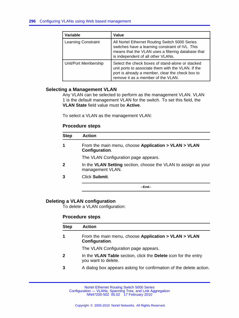
296 Configuring VLANs using Web based management
Variable Value
Learning Constraint All Nortel Ethernet Routing Switch 5000 Seriesswitches have a learning constraint of IVL. Thismeans that the VLAN uses a filtering database thatis independent of all other VLANs.
Unit/Port Membership Select the check boxes of stand-alone or stackedunit ports to associate them with the VLAN. If theport is already a member, clear the check box toremove it as a member of the VLAN.
Selecting a Management VLANAny VLAN can be selected to perform as the management VLAN. VLAN1 is the default management VLAN for the switch. To set this field, theVLAN State field value must be Active.
To select a VLAN as the management VLAN:
Procedure steps
Step Action
1 From the main menu, choose Application > VLAN > VLANConfiguration.
The VLAN Configuration page appears.
2 In the VLAN Setting section, choose the VLAN to assign as yourmanagement VLAN.
3 Click Submit.
--End--
Deleting a VLAN configurationTo delete a VLAN configuration:
Procedure steps
Step Action
1 From the main menu, choose Application > VLAN > VLANConfiguration.
The VLAN Configuration page appears.
2 In the VLAN Table section, click the Delete icon for the entryyou want to delete.
3 A dialog box appears asking for confirmation of the delete action.
Nortel Ethernet Routing Switch 5000 SeriesConfiguration — VLANs, Spanning Tree, and Link Aggregation
NN47200-502 05.02 17 February 2010
Copyright © 2005-2010 Nortel Networks. All Rights Reserved.
.

Flushing the MAC address table using Web-based management 297
Do one of the following:
• Click Yes to delete the VLAN configuration.
• Click Cancel to return to the VLAN Configuration pagewithout making changes.
--End--
Flushing the MAC address table using Web-based managementYou can flush the MAC address table of dynamically-learned MACaddresses. The MAC flush functionality allows you to flush:
• one MAC address
• all MAC addresses
• one VLAN
• one port or a list of ports
• one trunk
To flush MAC addresses from the MAC address table:
Procedure steps
Step Action
1 From the main menu, choose Configuration > MAC AddressTable.
The MAC Address Table configuration screen appears.
2 Select the type of MAC Flush.
3 Type the MAC address, the VLAN or trunk number, or the portnumber or range. These examples illustrate how to enter portranges for the Flush Port command.
Flushing out ports 1 and 2 on a standalone unit example
Flush Port 1,2
Flushing out ports 1-10 on unit 2 and 1-7 on unit 3 of astack example
Flush Port 2/1-10,3/1-7
4 Click Submit.
--End--
Nortel Ethernet Routing Switch 5000 SeriesConfiguration — VLANs, Spanning Tree, and Link Aggregation
NN47200-502 05.02 17 February 2010
Copyright © 2005-2010 Nortel Networks. All Rights Reserved.
.

298 Configuring VLANs using Web based management
Variable definitions
Variable Value
MAC Flush The type of addresses to flush from the MACaddress table. Choose from the following:• Address, enter the MAC address to flush
• VLAN, enter the VLAN number
• Port, enter the port number or the port range
• Trunk, enter the trunk number
• All
Nortel Ethernet Routing Switch 5000 SeriesConfiguration — VLANs, Spanning Tree, and Link Aggregation
NN47200-502 05.02 17 February 2010
Copyright © 2005-2010 Nortel Networks. All Rights Reserved.
.

299.
Configuring STP using Web basedmanagement
Setting the STP mode using Web-based ManagementTo set the STP operational mode using Web-based Management:
Procedure steps
Step Action
1 From the menu, select Applications > Spanning Tree >Operational Mode.
The Operational Mode page appears.
2 Select the Spanning Tree Administrative Mode from the list.
The available options are:
• STP Compatible
• RSTP
• MSTP
3 Click Submit.
A warning appears reminding you that a switch reset is requiredfor the change to take effect.
4 Click OK.
5 To reset the switch, choose Administration > Reset.
--End--
Creating and Managing STGs using Web-based ManagementThe Web-based Management screens detailed in this section allow for thecreation and management of Spanning Tree Groups.
Nortel Ethernet Routing Switch 5000 SeriesConfiguration — VLANs, Spanning Tree, and Link Aggregation
NN47200-502 05.02 17 February 2010
Copyright © 2005-2010 Nortel Networks. All Rights Reserved.
.

300 Configuring STP using Web based management
To configure STGs using Web-based Management, refer to the following:
• “Creating a Spanning Tree Group” (page 300)
• “Modifying a Spanning Tree Group” (page 301)
• “Deleting a Spanning Tree Group” (page 301)
• “Associating an STG with VLAN Membership” (page 302)
• “Spanning Tree Port Configuration” (page 303)
• “Modifying STG Bridge Information” (page 304)
Creating a Spanning Tree GroupTo create a Spanning Tree Group, follow this procedure:
Procedure steps
Step Action
1 From the menu, select Applications > Spanning Tree > GroupConfiguration.
The Group Configuration page appears.
2 In the STG Group Creation section, enter the information tocreate the new Spanning Tree Group. outlines the fields in thissection.
3 Click Submit.
The new Spanning Tree Group is created and displayed in theSTG Group Table section of the Group Configuration page.
The new Spanning Tree Group is disabled until you modify it byclicking the Modify button on the STG Group Table section.
--End--
Variable definitions
Variable Value
STP Group Index Choose the group number to be created.
Bridge Priority Select the desired priority from the list.
Hello Time Enter the desired hello time for this STG inseconds; the range is 1 to 10.
Max. Age time Enter the desired maximum age time for thisSTG in seconds; the range is 6 to 40.
Forward Delay Time Enter the desired forward delay time for thisSTG in seconds; the range is 4 to 30.
Nortel Ethernet Routing Switch 5000 SeriesConfiguration — VLANs, Spanning Tree, and Link Aggregation
NN47200-502 05.02 17 February 2010
Copyright © 2005-2010 Nortel Networks. All Rights Reserved.
.

Creating and Managing STGs using Web-based Management 301
Variable Value
Tagged BPDU on Tagged Port Set the frames as tagged (Yes) or untagged(No) on tagged ports.
VID used for Tagged BPDU Enter the VLAN ID for tagged BPDUs for thespecified STG.Note: The default VIDs are 4001 through 4008for STGs 1 through 8, respectively.
STP Multicast Address Enter the STP multicast MAC address.
Modifying a Spanning Tree GroupTo modify an existing Spanning Tree Group, follow this procedure:
Procedure steps
Step Action
1 From the menu, select Applications > Spanning Tree > GroupConfiguration.
The Group Configuration page appears.
2 In the STG Group Table section, click the Modify button for theSTG to be modified.
The Group Configuration page appears and allows the SpanningTree Group information to be edited.
3 Use the STG Group State field to enable or disable theselected Spanning Tree Group.
4 Make any additional changes to the Spanning Tree Group usingthe fields provided.
5 Click Submit.
--End--
Deleting a Spanning Tree GroupTo delete a Spanning Tree Group, follow this procedure:
Nortel Ethernet Routing Switch 5000 SeriesConfiguration — VLANs, Spanning Tree, and Link Aggregation
NN47200-502 05.02 17 February 2010
Copyright © 2005-2010 Nortel Networks. All Rights Reserved.
.

302 Configuring STP using Web based management
Procedure steps
Step Action
1 From the menu, select Applications > Spanning Tree > GroupConfiguration.
The Group Configuration page appears.
2 In the STG Group Table section, click the Delete button for theSTG to be deleted. (STG 1 can never be deleted.)
A message appears asking for confirmation of the deletion.
3 Click Yes.
--End--
Associating an STG with VLAN MembershipTo modify the association of a VLAN with an STG, follow this procedure:
Procedure steps
Step Action
1 From the menu, select Applications > Spanning Tree > VLANMembership.
The VLAN Membership page appears.
2 Refer to the following to add or delete a VLAN.
a To add a VLAN to an STG:
• Click the Modify button that appears in the Add VLANcolumn of the STG to be modified.The VLAN Membership modification page appears.
• In the Add VLAN Membership field, type the numbers ofthe VLANs to be added, separated by spaces.
• Click Submit.
b To remove a VLAN from an STG:
• Click the Modify button that appears in the RemoveVLAN column of the STG to be modified.
Nortel Ethernet Routing Switch 5000 SeriesConfiguration — VLANs, Spanning Tree, and Link Aggregation
NN47200-502 05.02 17 February 2010
Copyright © 2005-2010 Nortel Networks. All Rights Reserved.
.

Creating and Managing STGs using Web-based Management 303
The VLAN Membership deletion page appears.
• In the Remove VLAN Membership field, type thenumbers of the VLANs to be removed, separated byspaces.
• Click Submit.
--End--
Spanning Tree Port ConfigurationTo configure ports for participation in a Spanning Tree Group, follow thisprocedure:
The Spanning Tree -- Port Setting section does not list all ports on aswitch at one time. Click the links that appear at the bottom of the page toview the designated ports.
Procedure steps
Step Action
1 From the menu, select Applications > Spanning Tree > PortConfiguration .
The Port Configuration page appears.
2 From the STG Group section Group list, select the STG toconfigure.
3 Immediately under the STG Group section, click Submit.
4 With the desired STG selected, use the fields in the SpanningTree -- Port Setting section to denote which ports will participatein the STG.
The fields for this section are outlined in .
5 Immediately under the Spanning Tree -- Port Setting section,click Submit.
--End--
Nortel Ethernet Routing Switch 5000 SeriesConfiguration — VLANs, Spanning Tree, and Link Aggregation
NN47200-502 05.02 17 February 2010
Copyright © 2005-2010 Nortel Networks. All Rights Reserved.
.

304 Configuring STP using Web based management
Variable definitions
Variable Value
Participation This list is used to select the STG participationfor the port. The options are:• Normal Learning
• Fast Learning
• Disabled
Note: When an individual port is a trunkmember, changing this setting for one of thetrunk members changes the setting for allmembers of that trunk. Consider the effect thatchanging this value will have on the networktopology before making changes.The default setting is Normal Learning.
Priority The bridge spanning tree parameter thatprioritizes the lowest port path cost to the root.When one or more ports have the same pathcost, STP selects the path with the highestpriority (lowest numerical value).
Path Cost The bridge spanning tree parameter thatdetermines the lowest path cost to the root.
Modifying STG Bridge InformationTo modify the Spanning Tree Group Bridge information, follow thisprocedure:
Procedure steps
Step Action
1 From the menu, select Applications > Spanning Tree > BridgeInformation .
The Bridge Information page appears.
2 From the Group list in the STG Group section, select the STGto modify.
3 Immediately underneath the STG Group section, click theSubmit button.
4 In the fields provided, edit the information pertaining to theselected STG.
describes the fields that can be edited in the Spanning Tree --Bridge Information section.
Nortel Ethernet Routing Switch 5000 SeriesConfiguration — VLANs, Spanning Tree, and Link Aggregation
NN47200-502 05.02 17 February 2010
Copyright © 2005-2010 Nortel Networks. All Rights Reserved.
.

Creating and Managing STGs using Web-based Management 305
5 Click Submit.
--End--
Variable definitions
Variable Value
Bridge Priority Select the priority value of the bridge ID inhexadecimal notation, which is the mostsignificant byte of the bridge ID. The SpanningTree Algorithm uses this parameter todetermine the root bridge (or designatedbridge). For example, the bridge with thelowest bridge ID becomes the root bridge, withBridge Priority values compared first, followedby the hardware addresses.The default setting is 8000.
Bridge Hello Time The Hello Interval (the amount of timebetween transmissions of BPDUs) specified bymanagement for this bridge. This parametertakes effect only when this bridge becomes theroot bridge.Note: Although you can set the Hello Intervalfor a bridge using bridge management software,after the spanning tree computation processis complete, all bridges participating in thespanning tree network use the root bridge HelloInterval parameter value. If any bridge becomesthe root bridge, its Hello Interval parametervalue becomes the Actual Hello Intervalparameter value for all bridges participating inthe spanning tree network.The default is 2 seconds.
Bridge Maximum Age Time The Maximum Age Time parameter value thatthe root bridge uses. This value specifies themaximum age that a Hello message can attainbefore being discarded.Note: The root bridge Maximum Age Timeparameter value becomes the actual MaximumAge Time parameter value for all bridgesparticipating in the spanning tree network.
Nortel Ethernet Routing Switch 5000 SeriesConfiguration — VLANs, Spanning Tree, and Link Aggregation
NN47200-502 05.02 17 February 2010
Copyright © 2005-2010 Nortel Networks. All Rights Reserved.
.

306 Configuring STP using Web based management
Variable Value
Bridge Forward Delay The Forward Delay parameter value that theroot bridge uses. This value specifies theamount of time that the bridge ports remainin the Listening and Learning states beforeentering the Forwarding state.Note: The root bridge Forward Delay parametervalue becomes the actual Forward Delayparameter value for all bridges participating inthe spanning tree network.
Tagged BPDU on Tagged Port This parameter determines whether tagged oruntagged BPDUs are sent from a tagged port.
VID used for Tagged BPDU This parameter determines the VLAN ID sentwith the tagged BPDUs for the specified STG.
STP Multicast Address The STP multicast address to be used.
Configuring RSTP using Web-based managementThe Rapid Spanning Tree protocol (RSTP or IEEE 802.1w) reduces therecovery time after a network breakdown. It also maintains a backwardcompatibility with the IEEE 802.1d which was the Spanning Treeimplementation prior to RSTP. In certain configurations the recovery timeof RSTP can be reduced to less than 1 second.
RSTP also reduces the amount of flooding in the network by enhancingthe way the Topology Change Notification (TCN) packet is generated.
To configure RSTP using Web-based management, refer to the followingsections:
• “Configuring RSTP bridge settings” (page 306)
• “Configuring RSTP port settings” (page 308)
Configuring RSTP bridge settingsYou can view and configure the existing Spanning Tree (RSTP) bridgeswitch settings.
To configure the Spanning Tree (RSTP) bridge switch settings:
Procedure steps
Step Action
1 From the main menu, choose Application > Spanning Tree >Bridge Configuration.
Nortel Ethernet Routing Switch 5000 SeriesConfiguration — VLANs, Spanning Tree, and Link Aggregation
NN47200-502 05.02 17 February 2010
Copyright © 2005-2010 Nortel Networks. All Rights Reserved.
.

Configuring RSTP using Web-based management 307
The Spanning Tree (RSTP) - Bridge Configuration page appears.
--End--
Variable definitions
Variable Value
STP Priority The value of the writable portion of the Bridge ID. That is,the first two octets of the (8 octet long) Bridge ID. The other(last) 6 octets of the Bridge ID are given by the value ofdot1dBaseBridgeAddress. On bridges supporting IEEE 802.1tor IEEE 802.1w permissible values are 0-61440, in steps of4096.
DesignatedRoot
The bridge identifier of the root of the spanning tree asdetermined by the Spanning Tree Protocol as executed by thisnode. This value is used as the Root Identifier parameter in allConfiguration Bridge PDUs originated by this node.
Stp Root Cost The cost of the path to the root as seen from this bridge.
Stp Root Port The port number of the port which offers the lowest cost pathfrom this bridge to the root bridge.
Bridge MaxAge
The value that all bridges use for MaxAge when this bridgeacts as the root.
Note: 802.1D-1990 specifies that the range is related to thevalue of BridgeHelloTime. The granularity of this timer isspecified by 802.1D-1990 to be 1 second. A badValue error canbe returned if the value set is not a whole number.
Bridge HelloTime
The value that all bridges use for HelloTime when this bridgeacts as the root.
Note: The granularity of this timer is specified by 802.1D-1990to be 1 second. A badValue error can be returned if the valueset is not a whole number.
Bridge Forward Delay Time
The value that all bridges use for ForwardDelay when thisbridge acts as the root.
Note: 802.1D-1990 specifies that the range is related to thevalue of BridgeHelloTime. The granularity of this timer isspecified by 802.1D-1990 to be 1 second. A badValue error canbe returned if the value set is not a whole number.
Tx Hold Count The value used by the Port Transmit state machine to limit themaximum transmission rate.
PathCostDefault Type
The version of the Spanning Tree default Path Costs that areused by this Bridge.
Nortel Ethernet Routing Switch 5000 SeriesConfiguration — VLANs, Spanning Tree, and Link Aggregation
NN47200-502 05.02 17 February 2010
Copyright © 2005-2010 Nortel Networks. All Rights Reserved.
.

308 Configuring STP using Web based management
Configuring RSTP port settingsTo open the Spanning Tree (RSTP) - Port Configuration page:
Procedure steps
Step Action
1 From the main menu, choose Application > Spanning Tree >Port Configuration.
The Spanning Tree (RSTP) - Port Configuration page appears.
--End--
Variable definitions
Variable Value
Port The port number of the currently displayed unit.
STP Participation Enables or disables STP participation on the port. The default setting isDisabled.
Priority (hex) The bridge spanning tree parameter that prioritizes the lowest port path cost tothe root. When one or more ports have the same path cost, STP selects thepath with the highest priority (lowest numerical value).
Path Cost The bridge spanning tree parameter that determines the lowest path cost tothe root.
Admin EdgeStatus
The administrative value of the Edge Port parameter. A value of True indicatesthat this port is assumed to be an edge-port, and a value of False indicatesthat this port is assumed to be a nonedge-port.
An Edge Port goes directly to Forwarding state without delay. Edge portsdo not receive any Topology Change notifications and cannot influence theSpanning Tree Algorithm in detecting network loops. This is a particular portsetting, not a learning mode.
Oper Edge Status Can be True or False. This is set to False when AdminEdge is set to True andthe port receives BPDUs (any kind) or when AdminEdge is set to False.
Admin P2PStatus
The administrative point-to-point status of the LAN segment attached to thisport. A value of 0 indicates that this port is always treated as being connectedto a point-to-point link. A value of 1 indicates that this port is treated as havinga shared media connection. A value of 2 indicates that this port is consideredto have a point-to-point link if it is an Aggregator and all of its members areaggregatable, or if the MAC entity is configured for full duplex operation, eitherthrough auto-negotiation, or by management means.
Oper P2P Status This field indicates the operational point-to-point status of the LAN segmentattached to the port. It also indicates whether a port is considered to havea point-to-point connection. The value is determined by management or byauto-detection, as described in the AdminP2P object.
Nortel Ethernet Routing Switch 5000 SeriesConfiguration — VLANs, Spanning Tree, and Link Aggregation
NN47200-502 05.02 17 February 2010
Copyright © 2005-2010 Nortel Networks. All Rights Reserved.
.

Configuring MSTP using Web-based management 309
Variable Value
Oper ProtocolVersion
Displays the operational mode of the port.
Role The current role of the port as defined by Rapid Spanning Tree Protocol. Therole of a port can be Root, Designated, Alternate, or Backup.
State The current state of the port as defined by application of the Spanning TreeProtocol. This state controls what action a port takes on reception of a frame.If the bridge detects a port that is malfunctioning, the port is placed into thedisabled state.
Configuring MSTP using Web-based managementTo configure MSTP using Web-based management, refer to the followingsections:
• “Creating MSTI instances” (page 309)
• “Configuring MSTI bridge settings” (page 310)
• “Adding VLANs to the MSTI” (page 312)
• “Configuring Cist ports” (page 313)
• “Configuring MSTI port properties” (page 314)
Creating MSTI instancesTo create MSTI instances:
Procedure steps
Step Action
1 From the main menu, choose Applications > Spanning Tree >Bridge Configuration.
The MSTP Bridge Configuration page appears.
2 To create an MSTI, choose an MSTI from the Spanning Tree -Msti Bridge Creation list, and click Submit.
The new MSTI instance appears in the Spanning Tree - MstiBridge Configuration section.
The following table describes the items on the Msti BridgeConfiguration page.
--End--
Nortel Ethernet Routing Switch 5000 SeriesConfiguration — VLANs, Spanning Tree, and Link Aggregation
NN47200-502 05.02 17 February 2010
Copyright © 2005-2010 Nortel Networks. All Rights Reserved.
.

310 Configuring STP using Web based management
Variable definitions
Section Variable Value
Displays a configuration page for the CIST.
BridgeRegionalRoot
Port and the MAC address of the root switch.
BridgePriority
The priority value of the bridge ID in hexadecimal notation, which isthe most significant byte of the bridge ID.
Root Cost The cost of the path to the root as seen from this bridge.
SpanningTree - CISTBridge Configuration
Root Port The port number of the port which offers the lowest path cost fromthis bridge to the root bridge.
Displays a configuration page for the MSTI.
Deletes the MSTI.
Msti Displays the index of MSTP.
BridgeRegionalRoot
Displays the unique Bridge Identifier of the bridge.
BridgePriority
Type the priority value of the bridge ID in hexadecimal notation,which is the most significant byte of the bridge ID.
Root Cost The cost of the path to the root as seen from this bridge.
Root Port The port number of the port which offers the lowest path cost fromthis bridge to the root bridge.
SpanningTree - MstiBridge Configuration
State Specifies whether the bridge instance is enabled or disabled.
SpanningTree - Msti Bridge Creation
Msti Displays the index of MSTP. To add an MSTI, choose an MSTIidentifier from the list and click submit.
Configuring MSTI bridge settingsTo configure the MSTI bridge settings on the switch:
Procedure steps
Step Action
1 From the MSTP Bridge Configuration page, under SpanningTree - Msti Bridge Configuration, choose the Msti BridgeConfiguration Action icon.
Nortel Ethernet Routing Switch 5000 SeriesConfiguration — VLANs, Spanning Tree, and Link Aggregation
NN47200-502 05.02 17 February 2010
Copyright © 2005-2010 Nortel Networks. All Rights Reserved.
.

Configuring MSTP using Web-based management 311
The Msti Bridge Configuration page appears.
--End--
Variable definitions
Variable Value
Msti The Multiple Spanning Tree instance.
State Used to control whether the bridge instance is enabled or disabled.
Bridge Priority The writable portion of the MSTI bridge identifier comprising the firsttwo octets.
Bridge Regional Root Indicates the MSTI regional root identifier value for the MSTI. Allconfiguration bridge PDUs originated by this node use this value asthe MSTI Regional Root Identifier parameter.
Root Cost The cost of the path to the MSTI regional root as seen by thisbridge.
Root Port The port number of the port that offers the lowest path cost from thisbridge to the MSTI region root bridge.
Configuring CIST bridge settingsTo configure CIST settings on the switch:
Procedure steps
Step Action
1 From the MSTP Bridge Configuration page, under SpanningTree - Msti Bridge Configuration, choose the CIST BridgeConfiguration icon.
The CIST Bridge Configuration page appears.
--End--
Variable definitions
Section Variable Value
BridgePriority
The value of the writable portion of the bridge identifier comprisingthe first two octets.
Bridge MaxAge
The value in seconds that all bridges use for MaxAge when thisbridge acts as the root. The range is 6 to 40.
BridgeForwardDelay Time
The value in seconds that all bridges use for ForwardDelay whenthis bridge acts as the root. IEEE 802.1D specifies that the rangefor this parameter is related to the value of Bridge Max Age. Therange is 4 to 30.
SpanningTree - CISTBridge Configuration
Nortel Ethernet Routing Switch 5000 SeriesConfiguration — VLANs, Spanning Tree, and Link Aggregation
NN47200-502 05.02 17 February 2010
Copyright © 2005-2010 Nortel Networks. All Rights Reserved.
.

312 Configuring STP using Web based management
Section Variable Value
Tx HoldCount
The value used by the Port Transmit state machine to limit themaximum transmission rate.
PathCostDefaultType
The version of the spanning tree default path costs that this bridgeuses. A 16-bit value uses the 16-bit default path costs from IEEEStandard 802.1D-1998. A 32-bit value uses the 32-bit default pathcosts from IEEE Standard 802.1t.
Max HopCount
The maximum hop count value in 1/100 seconds. The value mustbe a multiple of 100. The range is 600 to 4000.
Root Port The highest possible value for the MSTI ID in this mode.
Numberof MstiSupported
The number of MSTI supported in this mode.
Config IdSelector
The MSTP config ID selector. The default value is 0.
RegionName
The MSTP region name. The default value is the bridge MACaddress.
RegionVersion
The MSTP region version. The default value is 0.
SpanningTree - RegionConfiguration
ConfigDigest
The configuration digest value for this region.
Adding VLANs to the MSTITo add a VLAN to an MSTI:
Procedure steps
Step Action
1 From the main menu, choose Application > Spanning Tree >Bridge VLAN.
The MSTP VLAN page appears.
The table displays the current VLAN membership for the MSTIs.
2 To add a VLAN:
a Click the modification icon in the Add VLAN column for theCIST or MSTI.
The MSTP VLAN Membership (Add) page appears.
Nortel Ethernet Routing Switch 5000 SeriesConfiguration — VLANs, Spanning Tree, and Link Aggregation
NN47200-502 05.02 17 February 2010
Copyright © 2005-2010 Nortel Networks. All Rights Reserved.
.

Configuring MSTP using Web-based management 313
b Enter the ID numbers of the VLANs you want to add to theMSTI.
c Click Submit.
The VLAN is added to the current VLAN Membership column inthe appropriate MSTI row.
3 To remove a VLAN:
a Click the modification icon in the Remove VLAN column.
The VLAN Membership (Remove) page appears.
b Enter the number of the VLANs you want to remove from theMSTI.
c Click Submit.
The VLAN is removed from the Current VLAN Membershipcolumn in the appropriate CIST or MSTI row.
--End--
Configuring Cist portsTo configure CIST ports:
Procedure steps
Step Action
1 From the main menu, choose Application > Spanning Tree(MSTP) > Cist Port Configuration.
The Cist Port Configuration page appears.
--End--
Variable definitions
Variable Value
Port Indicates the name of the port.
STP Participation Provides information about current participation for a port in CIST (in thiscase). In new implementation this can be only Enabled or Disabled. Enabledmeans Normal Learning, like in STP802.1d mode. Disabled means that portdoesn’t transmit any BPDUs and is not under the influence of Spanning TreeAlgorithm (STA).
Nortel Ethernet Routing Switch 5000 SeriesConfiguration — VLANs, Spanning Tree, and Link Aggregation
NN47200-502 05.02 17 February 2010
Copyright © 2005-2010 Nortel Networks. All Rights Reserved.
.

314 Configuring STP using Web based management
Variable Value
Priority Indicates the four most significant bits of the Port Identifier for a givenSpanning Tree instance. The value can be modified independently for eachSpanning Tree instance supported by the Bridge. The values that are set forPort Priority must be in steps of 16.
Path Cost The cost of the path to the root as seen from this bridge.
Admin EdgeStatus
The administrative value of the Edge Port parameter. A value of True indicatesthat this port is assumed to be an edge-port and a value of False indicates thatthis port is assumed to be a nonedge-port.
An Edge Port goes directly to Forwarding state without delay. Edge portsdo not receive any Topology Change notifications and cannot influence theSpanning Tree Algorithm in detecting network loops. This is a particular portsetting, not a learning mode.
Oper Edge Status Can be True or False. This is set to False when AdminEdge is set to True andthe port receives BPDUs (any kind) or when AdminEdge is set to False.
Admin P2PStatus
The administrative point-to-point status of the LAN segment attached to thisport. A value of 0 indicates that this port is always treated as being connectedto a point-to-point link. A value of 1 indicates that this port is treated as havinga shared media connection. A value of 2 indicates that this port is consideredto have a point-to-point link if it is an Aggregator and all of its members areaggregatable, or if the MAC entity is configured for full duplex operation, eitherthrough auto-negotiation, or by management means.
Oper P2P Status This field indicates the operational point-to-point status of the LAN segmentattached to the port. It also indicates whether a port is considered to havea point-to-point connection. The value is determined by management or byauto-detection, as described in the AdminP2P object.
Hello Time Sets the hello time on the single or multiple port.
Role The current role of the port as defined by the Multiple Spanning Tree Protocol.The role of a port can be Root, Designated, Alternate, or Backup.
State Indicates the current state of the port as defined by the Multiple SpanningTree Protocol. The state of a port can be Forwarding in one instance, andDiscarding (Blocking) in another.
Configuring MSTI port propertiesTo configure MSTI port properties:
Procedure steps
Step Action
1 From the main menu, choose Application > Spanning Tree(MSTP) > Msti Port Configuration.
Nortel Ethernet Routing Switch 5000 SeriesConfiguration — VLANs, Spanning Tree, and Link Aggregation
NN47200-502 05.02 17 February 2010
Copyright © 2005-2010 Nortel Networks. All Rights Reserved.
.

Configuring MSTP using Web-based management 315
The Msti Port Configuration page appears.
--End--
Variable definitions
Section Variable Value
MST Instance Msti The MSTI instance ID.
Priority Indicates the four most significant bits of the Port Identifierfor a given spanning tree instance. You can modify this itemindependently for each spanning tree instance the bridgesupports.
Spanning Tree -Msti Port Setting
Path Cost The contribution of this port to the cost of paths towards theMSTI root that include this port.
Nortel Ethernet Routing Switch 5000 SeriesConfiguration — VLANs, Spanning Tree, and Link Aggregation
NN47200-502 05.02 17 February 2010
Copyright © 2005-2010 Nortel Networks. All Rights Reserved.
.

316 Configuring STP using Web based management
Nortel Ethernet Routing Switch 5000 SeriesConfiguration — VLANs, Spanning Tree, and Link Aggregation
NN47200-502 05.02 17 February 2010
Copyright © 2005-2010 Nortel Networks. All Rights Reserved.
.

317.
Configuring MLT using Web basedmanagement
The Web-based Management screens detailed in this section allow for thecreation and management of Multi-Link trunks.
Creating a Multi-Link trunkTo create a MLT, follow this procedure:
Procedure steps
Step Action
1 From the menu, select Applications > Multi-Link Trunk >Group. The Multi-Link Trunk Group page appears.
2 In the fields provided, fill in the information for the MLT to becreated. outlines the fields on this page.
3 Click Submit.
--End--
Variable definitions
Variable Value
Trunk Members Type the port numbers to associate with thecorresponding trunk.Note: Between two and eight switch ports canbe configured together as members of a trunk toa maximum of 32 trunks. Switch ports can onlybe assigned to be a member of a single trunk.
Nortel Ethernet Routing Switch 5000 SeriesConfiguration — VLANs, Spanning Tree, and Link Aggregation
NN47200-502 05.02 17 February 2010
Copyright © 2005-2010 Nortel Networks. All Rights Reserved.
.

318 Configuring MLT using Web based management
Variable Value
STP Choose the parameter that allows the specifiedtrunk to participate in the spanning tree group.This setting overrides those of the individualtrunk members. Selecting Fast shortensthe state transition timer by two seconds.Refer to “Configuring Spanning Tree GroupParticipation” (page 318)on page 111 for acomplete explanation of this process.
Trunk Mode Choose the preferred trunk load-balancingmode: basic or advanced.
Trunk Name Type a character string to create a uniquename to identify the trunk, for example,Trunk1.The name, if chosen carefully, can providemeaningful information to you. For example,S1:T1 to FS2 indicates that Trunk1, in Switch1connects to File Server 2.
Trunk Status Choose to enable or disable any of the existingMulti-Link trunks.Note: When a trunk is not active (Trunk Statusfield set to Disabled), configuration changes donot take effect until the Trunk Status field is setto Enabled.
Configuring Spanning Tree Group ParticipationAfter a Multi-Link trunk has been established, MLT participation in aSpanning Tree Group can be configured. To configure STG participation,the MLT must have a Trunk Status of Enabled. Refer to “Creating aMulti-Link trunk” (page 317)on page 109 for information about this process.
To configure Spanning Tree Group participation, follow this procedure:
Procedure steps
Step Action
1 From the menu, select Applications > Multi-Link Trunk >Group. The Multi-Link Trunk Group page appears.
2 Click the button in the STP column for the row that representsthe Multi-Link trunk that is to be configured.
The Multi-Link Trunk Spanning Tree Settings page appears.
3 Set the STP Learning list to reflect the desired learning mode.The three options available are:
Nortel Ethernet Routing Switch 5000 SeriesConfiguration — VLANs, Spanning Tree, and Link Aggregation
NN47200-502 05.02 17 February 2010
Copyright © 2005-2010 Nortel Networks. All Rights Reserved.
.

Monitoring an MLT 319
• Normal -- Sets the learning mode to normal.
• Fast -- Sets the learning mode to fast.
• Disable -- Disables learning.
4 Click Submit.
--End--
Monitoring an MLTTo monitor the bandwidth usage of the MLT, follow these steps:
MLT utilization statistics are displayed in the Multi-Link Trunk UtilizationTable section.
Procedure steps
Step Action
1 From the menu, select Applications > Multi-Link Trunk >Utilization. The Utilization page appears.
2 In the Multi-Link Trunk Utilization Selection section, select thetrunk to be monitored in the Trunk list and the type of traffic tobe monitored in the Traffic Type list.
3 Click Submit.
--End--
Nortel Ethernet Routing Switch 5000 SeriesConfiguration — VLANs, Spanning Tree, and Link Aggregation
NN47200-502 05.02 17 February 2010
Copyright © 2005-2010 Nortel Networks. All Rights Reserved.
.

320 Configuring MLT using Web based management
Nortel Ethernet Routing Switch 5000 SeriesConfiguration — VLANs, Spanning Tree, and Link Aggregation
NN47200-502 05.02 17 February 2010
Copyright © 2005-2010 Nortel Networks. All Rights Reserved.
.

321.
Configuring ADAC using Web basedManagement
You can configure the settings for Auto-Detection and Auto-Configuration(ADAC) of Nortel IP Phones using Web-based management.
This section contains the following topics:
• “Configuring global ADAC properties” (page 321)
• “Configuring ADAC port properties” (page 322)
• “Configuring ADAC MAC address ranges” (page 323)
• “Configuring ADAC Port Detection” (page 324)
Configuring global ADAC propertiesTo configure the global ADAC settings:
Procedure steps
Step Action
1 From the main menu, choose Application > ADAC > GlobalConfiguration.
The Global Configuration page appears.
describes the fields in the Global Configuration page.
2 From the ADAC list, select Enabled.
3 Choose the Operating Mode.
4 In the Traps Control Status field, enable or disable trapnotifications.
5 Enter the Voice VLAN ID.
6 Choose the Call Server port and unit and the Uplink port and unitfrom the lists.
Nortel Ethernet Routing Switch 5000 SeriesConfiguration — VLANs, Spanning Tree, and Link Aggregation
NN47200-502 05.02 17 February 2010
Copyright © 2005-2010 Nortel Networks. All Rights Reserved.
.

322 Configuring ADAC using Web based Management
7 Click Submit.
--End--
Variable definitions
Variable Value
ADAC Enables and disables ADAC.
ADAC Admin State Enables and disables ADAC (sets the adminstate).
ADAC Oper State Read-only: Displays the ADAC operating state,either Enabled or Disabled
Operating Mode Sets the ADAC operation mode:• Tagged Frames: IP Phones send tagged
frames.
• Untagged Frames Advanced: IP Phonessend untagged frames, and the VoiceVLAN is created.
• Untagged Frames Basic: IP Phones senduntagged frames, and the Voice VLAN isnot created.
Traps Control Status Enables and disables ADAC trap notifications.
Voice VLAN ID Sets the Voice VLAN ID.
Call Server Port Sets the Call Server port.
Uplink Port Sets the Uplink port.
Configuring ADAC port propertiesTo configure the ADAC port settings:
Procedure steps
Step Action
1 From the main menu, choose Application > ADAC > PortConfiguration.
The Port Configuration page appears.
2 Choose the Auto-Detection setting for each port from the listsas required.
3 Type the Tagged-Frames Port VLAN ID (PVID) into theTagged-Frames PVID box for each port. A value of 0 meansthe PVID remains unchanged.
Nortel Ethernet Routing Switch 5000 SeriesConfiguration — VLANs, Spanning Tree, and Link Aggregation
NN47200-502 05.02 17 February 2010
Copyright © 2005-2010 Nortel Networks. All Rights Reserved.
.

Configuring ADAC MAC address ranges 323
4 Choose the Tagged-Frames Tagging mode setting for eachport from the list.
5 Click Submit.
--End--
The following Type values may be displayed:
• CS - Call Server port
• U - Uplink port
• T - Telephone port
Configuring ADAC MAC address rangesConfigure the ADAC MAC address ranges.
Procedure steps
Step Action
1 From the main menu, choose Applications > ADAC > MACRange Table.
The MAC Range Table page appears.
describes the fields in the MAC Range Table page.
2 Type the Low End and High End MAC addresses for the newrange you want to add.
3 Click Submit.
--End--
Variable definitions
Section Variable Value
Operation From this field, you can choose to performone of the following actions:
• Reset To Defaults: resets the MACaddress range to default values.
• Delete All Ranges: deletes all existingMAC address ranges.
ADAC MACRange TableControl
Nortel Ethernet Routing Switch 5000 SeriesConfiguration — VLANs, Spanning Tree, and Link Aggregation
NN47200-502 05.02 17 February 2010
Copyright © 2005-2010 Nortel Networks. All Rights Reserved.
.
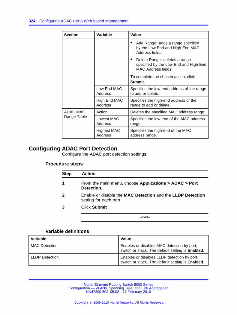
324 Configuring ADAC using Web based Management
Section Variable Value
• Add Range: adds a range specifiedby the Low End and High End MACAddress fields.
• Delete Range: deletes a rangespecified by the Low End and High EndMAC Address fields.
To complete the chosen action, clickSubmit.
Low End MACAddress
Specifies the low-end address of the rangeto add or delete.
High End MACAddress
Specifies the high-end address of therange to add or delete.
Action Deletes the specified MAC address range.
Lowest MACAddress
Specifies the low-end of the MAC addressrange.
ADAC MACRange Table
Highest MACAddress
Specifies the high-end of the MACaddress range.
Configuring ADAC Port DetectionConfigure the ADAC port detection settings.
Procedure steps
Step Action
1 From the main menu, choose Applications > ADAC > PortDetection.
2 Enable or disable the MAC Detection and the LLDP Detectionsetting for each port.
3 Click Submit
--End--
Variable definitions
Variable Value
MAC Detection Enables or disables MAC detection by port,switch or stack. The default setting is Enabled.
LLDP Detection Enables or disables LLDP detection by port,switch or stack. The default setting is Enabled.
Nortel Ethernet Routing Switch 5000 SeriesConfiguration — VLANs, Spanning Tree, and Link Aggregation
NN47200-502 05.02 17 February 2010
Copyright © 2005-2010 Nortel Networks. All Rights Reserved.
.

325.
Configuring LACP using Web basedmanagement
To configure Link Aggregation using Web-based management, refer tothe following sections
• “Bridge Configuration page” (page 325)
• “Port Configuration page” (page 325)
• “Port Statistics page” (page 326)
Bridge Configuration pageTo configure LACP bridge properties:
Procedure steps
Step Action
1 From the main menu, choose Application > Link Aggregation> Bridge Configuration.
The LACP Bridge Configuration page appears.
--End--
Variable definitions
Variable Value
System Priority Set system priority to all the LACP enabled aggregators.
Collector maxdelay
The value of this 16-bit read-write attribute defines the maximum delay, intens of microseconds, that can be imposed by the Frame Collector betweenreceiving a frame from an Aggregator Parser, and either delivering the frameto its MAC Client or discarding the frame. This is a read-only value.
Port Configuration pageTo configure LACP ports:
Nortel Ethernet Routing Switch 5000 SeriesConfiguration — VLANs, Spanning Tree, and Link Aggregation
NN47200-502 05.02 17 February 2010
Copyright © 2005-2010 Nortel Networks. All Rights Reserved.
.
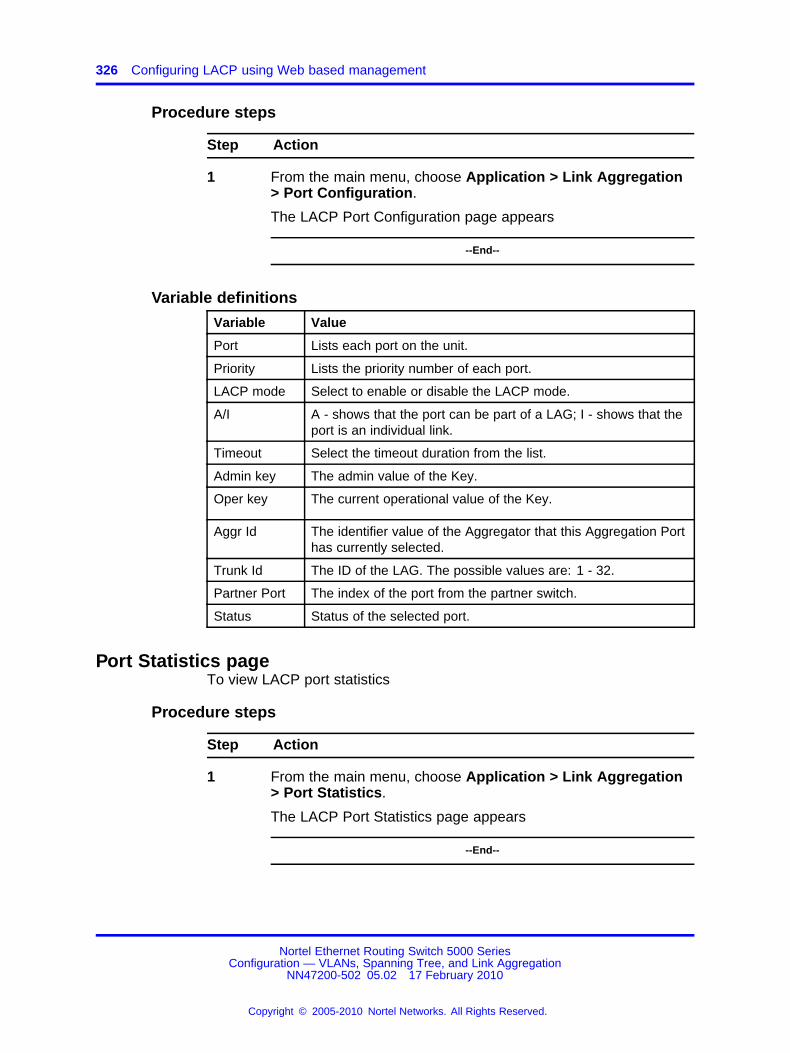
326 Configuring LACP using Web based management
Procedure steps
Step Action
1 From the main menu, choose Application > Link Aggregation> Port Configuration.
The LACP Port Configuration page appears
--End--
Variable definitions
Variable Value
Port Lists each port on the unit.
Priority Lists the priority number of each port.
LACP mode Select to enable or disable the LACP mode.
A/I A - shows that the port can be part of a LAG; I - shows that theport is an individual link.
Timeout Select the timeout duration from the list.
Admin key The admin value of the Key.
Oper key The current operational value of the Key.
Aggr Id The identifier value of the Aggregator that this Aggregation Porthas currently selected.
Trunk Id The ID of the LAG. The possible values are: 1 - 32.
Partner Port The index of the port from the partner switch.
Status Status of the selected port.
Port Statistics pageTo view LACP port statistics
Procedure steps
Step Action
1 From the main menu, choose Application > Link Aggregation> Port Statistics.
The LACP Port Statistics page appears
--End--
Nortel Ethernet Routing Switch 5000 SeriesConfiguration — VLANs, Spanning Tree, and Link Aggregation
NN47200-502 05.02 17 February 2010
Copyright © 2005-2010 Nortel Networks. All Rights Reserved.
.

Port Statistics page 327
Variable definitions
Variable Value
LACPDUsRx Denotes the number of valid LACPDUsreceived on this Aggregation Port. Thisvalue is read-only.
MarkerPDUsRx Signifies the number of valid Marker PDUsreceived on this Aggregation Port. Thisvalue is read-only.
MarkerResponsePDUsRx The number of valid Marker ResponsePDUs received on this Aggregation Port.This value is read-only.
UnknownPDUsRx Indicates the number of frames receivedthat can
• Carry the Slow Protocols Ethernet Typevalue (43B.4), but contain an unknownPDU.
• Are addressed to the Slow Protocolsgroup MAC Address (43B.3), but do notcarry the Slow Protocols Ethernet Type.
This value is read-only.
IllegalPDURx Denotes the number of frames receivedthat carry the Slow Protocols EthernetType value (43B.4), but contain a badlyformed PDU or an illegal value of ProtocolSubtype (43B.4). This value is read-only.
LACPDUsTx Signifies the number of LACPDUs that aretransmitted on this Aggregation Port. Thisvalue is read-only.
MarkerPDUsTx Displays the number of Marker PDUstransmitted on this Aggregation Port. Thisvalue is read-only.
MarkerResponsePDUsTx Indicates the number of Marker ResponsePDUs that are transmitted on thisAggregation Port. This value is read-only.
Nortel Ethernet Routing Switch 5000 SeriesConfiguration — VLANs, Spanning Tree, and Link Aggregation
NN47200-502 05.02 17 February 2010
Copyright © 2005-2010 Nortel Networks. All Rights Reserved.
.

328 Configuring LACP using Web based management
Nortel Ethernet Routing Switch 5000 SeriesConfiguration — VLANs, Spanning Tree, and Link Aggregation
NN47200-502 05.02 17 February 2010
Copyright © 2005-2010 Nortel Networks. All Rights Reserved.
.


Nortel Ethernet Routing Switch 5000 Series
Configuration — VLANs, Spanning Tree, and Link AggregationRelease: 6.1Publication: NN47200-502Document revision: 05.02Document release date: 17 February 2010
Copyright © 2005-2010 Nortel Networks. All Rights Reserved.
While the information in this document is believed to be accurate and reliable, except as otherwise expressly agreed to in writingNORTEL PROVIDES THIS DOCUMENT "AS IS" WITHOUT WARRANTY OR CONDITION OF ANY KIND, EITHER EXPRESSOR IMPLIED. The information and/or products described in this document are subject to change without notice.
Nortel, Nortel Networks, the Nortel logo, and the Globemark are trademarks of Nortel Networks.
All other trademarks are the property of their respective owners.
To provide feedback or to report a problem in this document, go to www.nortel.com/documentfeedback.
www.nortel.com