Embed Size (px)
Citation preview
®
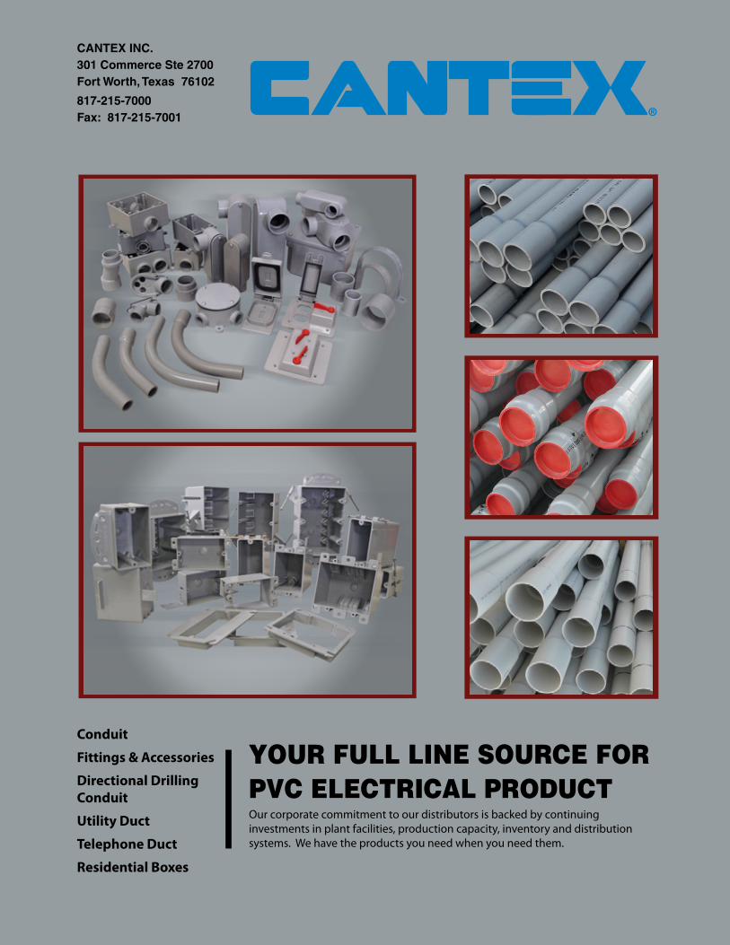
YOUR FULL LINE SOURCE FOR PVC ELECTRICAL PRODUCTOur corporate commitment to our distributors is backed by continuing investments in plant facilities, production capacity, inventory and distribution systems. We have the products you need when you need them.
Conduit
Fittings & Accessories
Directional Drilling
Conduit
Utility Duct
Telephone Duct
Residential Boxes
CANTEX INC.301 Commerce Ste 2700Fort Worth, Texas 76102
817-215-7000 Fax: 817-215-7001

Table of Contents
About CANTEX® · · · · · · · · · · · · · · · · · · · · · · · · · · · · · · · · · · · · · · · · · 4-6
Schedule 40 / Schedule 80 Fittings & Accessories · · · · · · · · · · · · · · · · · · · · · · 9-17 Couplings, Female Adapters, Terminal Adapters, Pipe Straps, Expansion Couplings, Reducers, Box Adapters, End Caps, Molded Sch. 40 End Bells, Plugs, Pull Elbows, Sealing Washers, Strain Relief Connectors, Insulating Bushings, Sch. 40 Longline Couplings, Sch. 40 Swedged Couplings, Sch. 40 Split Sleeve Coupling, Fabricated End Bells
Standard Radius Elbows, Plain End & Bell End · · · · · · · · · · · · · · · · · · · · · · · · 18-21
Sch. 40 Special Radius Elbows, Plain End & Bell End · · · · · · · · · · · · · · · · · · · · 22-34
Sch. 80 Standard Radius Elbows, Plain End & Bell End · · · · · · · · · · · · · · · · · · · 35-38
Sch. 80 Special Radius Elbows, Plain End & Bell End · · · · · · · · · · · · · · · · · · · · 39-43
Conduit Bodies · · · · · · · · · · · · · · · · · · · · · · · · · · · · · · · · · · · · · · · · · 47-49
Junction Boxes, Floor Boxes & Accessories · · · · · · · · · · · · · · · · · · · · · · · · · 50-51
Exposed Electrical Boxes & Weatherproof Covers · · · · · · · · · · · · · · · · · · · · · · 55-67
Fittings for Type EB and DB Utility Duct · · · · · · · · · · · · · · · · · · · · · · · · · · · · 71-76 Terminal Adapters, Female Adapters, Longline Couplings, 5° Couplings Fabricated, TC6 End Bells, Reducers, TC6 End Bells, Stoppers, Caps, Poly Plugs
Special Radius Elbows for Type EB and DB Utility Duct Bell End · · · · · · · · · · · · · 77-84
Type EB/DB Accessories · · · · · · · · · · · · · · · · · · · · · · · · · · · · · · · · · · · · 87-93 Service Entrance Caps, Meter Offsets, Offsets, Expansion Joints, Service Risers, Spacers
Schedule 40 Conduit · · · · · · · · · · · · · · · · · · · · · · · · · · · · · · · · · · · · · · · 97
Schedule 80 Conduit · · · · · · · · · · · · · · · · · · · · · · · · · · · · · · · · · · · · · · · 98
Forte-Duct® · · · · · · · · · · · · · · · · · · · · · · · · · · · · · · · · · · · · · · · · · · · · 99
Split Duct & Accessories · · · · · · · · · · · · · · · · · · · · · · · · · · · · · · · · · · · · 100
NEMA DBHM Utility Duct, NEMA EBHM Utility Duct, DB-100 · · · · · · · · · · · · · · · · 101-102
P&C Flexible Utility Duct · · · · · · · · · · · · · · · · · · · · · · · · · · · · · · · · · · · · · 103
EZ-Flex® Nonmetallic Tubing, ENT Accessories and ENT Boxes · · · · · · · · · · · · · · 107-109
Enviro-Flex Liquid Tight Conduit & Fittings · · · · · · · · · · · · · · · · · · · · · · · · · · 113-115
Direction Drilling Schedule 40 Conduit · · · · · · · · · · · · · · · · · · · · · · · · · · · · 117-119
Telephone Conduit and Fittings · · · · · · · · · · · · · · · · · · · · · · · · · · · · · · · · 123-138
Solvent Cement & Primer · · · · · · · · · · · · · · · · · · · · · · · · · · · · · · · · · · · · 141
EZ Box® Residential Boxes · · · · · · · · · · · · · · · · · · · · · · · · · · · · · · · · · · · 145-164
Conduit Installation Guidelines · · · · · · · · · · · · · · · · · · · · · · · · · · · · · · · · · 168-173
Conduit Engineering and Design Data · · · · · · · · · · · · · · · · · · · · · · · · · · · · 174-177
Conduit & Utility Duct Packaging Data · · · · · · · · · · · · · · · · · · · · · · · · · · · · · 178-179
Limited Warranty · · · · · · · · · · · · · · · · · · · · · · · · · · · · · · · · · · · · · · · · · 180
Authorized Distributor Policy · · · · · · · · · · · · · · · · · · · · · · · · · · · · · · · · · · 181-182
PVC PRODUCTSCANTEX is a leading producer of PVC products, with eight manufacturing facilities located strategically from east to west across the country. These facilities feature some of the most modern production equipment and advanced process technology found anywhere in the industry. Production facilities include extrusion, injection molding, and fabrication processes to produce the broad lines of PVC Products which serve the power, utility, building construction, and communications markets.
CANTEX PVC Products had its beginning over 40 years ago, as a division of a national corporation in the utility and building construction industry. The Plastics Division grew steadily in size and importance. Its product lines expanded into several major categories:
• Electrical distributors and contractors were provided with a broad line of PVC conduit and fi ttings.
• Power and utility companies were supplied with underground PVC duct and fi ttings.
• For the communications industry, PVC conduit and fi ttings were made available to telephone and cable companies for underground cable installations.
• Municipal public works needs were met with PVC pipe for distribution and collection.
• The commercial market need was fulfi lled with PVC plumbing pipe.
ELECTRICAL PRODUCT LINECANTEX offers a complete line of extruded and injection molded electrical conduit, duct, fi ttings, accessories, switch and outlet boxes. Products include a full range of sizes in:
• Schedule 40 & 80 Conduit
• Electrical Fittings & Accessories – Molded & Fabricated
• Schedule 40 Conduit for Directional Drilling Applications
• Utility Duct – NEMA TC-6 & 8 - EB35, DB60, DB100, DB120
• Schedule 40 Forte-Duct® Cellular Core PVC Conduit
• Duct Fittings & Accessories
• Elbows, Bends & Sweeps – Standard & Special Radius
• EZ-FLEX® Electrical Nonmetallic Tubing & Fittings
• ENVIRO-FLEX® Liquid Tight Conduit & Fittings
• Telephone Conduit – Types B-C-D
• EZ BOX® Wall and Ceiling Switch and Outlet Boxes
• Cements
SERVICECANTEX stands for a commitment to service – service that puts the customer fi rst. Our effi cient transportation system means on-time deliveries anywhere in the U.S. The CANTEX customer service team is staffed by professionals who provide immediate response and effective communications about orders and shipments.
At the NEW CANTEX, WE WORK FOR THE CUSTOMER.
PVC Electrical Products ®
4
INDUSTRY ORGANIZATIONS
CANTEX actively supports those organizations which set standards and promote professional practices in the electrical industry. These include NEMRA, NAED, IAEI, IEEE, along with other associations in the construction industry.
QUALITY ASSURANCE
CANTEX has a comprehensive quality control program to ensure compliance with industry standards established by Underwriters Laboratories, National Electrical Code, the American Society for Testing and Materials and Canadian Standards Association.
From virgin raw materials blended into compounds through extrusion or injection molding to fi nal inspection and testing of the fi nished product, the manufacturing process is monitored to make sure quality standards are met or exceeded.
Each plant is graded and held accountable for the quality control performance of its total output.
To further strengthen the company’s goal for quality products, a centralized quality control review procedure assures that every plant is producing at a consistent level of quality for all similar products. You know you’re getting the very best every time you buy from CANTEX.
Schedule 40 Conduit UL 651, NEMA TC-2 and NEC-Article 352 CSA C22.2 No. 211.2
Schedule 80 Conduit UL 651, NEMA TC-2 and NEC-Article 352
PVC Electrical Fittings Fittings for electrical applications conform to one or more of the following specifi caytions: NEMA TC-3 and UL 514B, UL651, NEMA TC-6&8, ASTM F-512, UL 50, CSA 22.2 No. 211.2 85-M89
Utility Duct - Extra Strengh NEMA TC 6&8 and ASTM F-512
Utility Duct Fittings NEMA TC-9
EZ-FLEX ENT (Electrical Nonmetallic Tubing) & Fittings NEMA TC-13 and NEC Article 362 UL 1653
ENVIRO-FLEX Liquidtight Conduit UL1660, NEC 356 CSA 22.2 No. 227.2.1
ENVIRO-FLEX Liquidtight Fittings UL 514B and NEMA FB-1
PVC ELECTRICAL STANDARDS BY PRODUCT
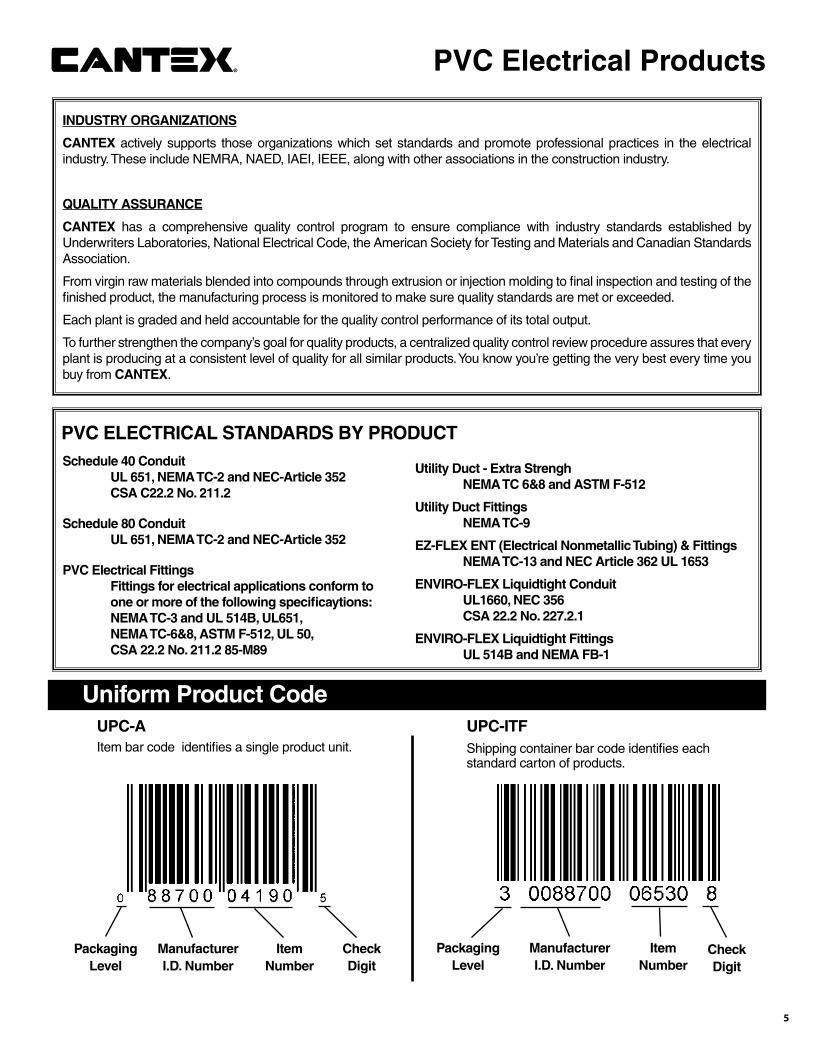
Uniform Product CodeUPC-A Item bar code identifi es a single product unit.
ManufacturerI.D. Number
ItemNumber
CheckDigit
UPC-ITFShipping container bar code identifi es each standard carton of products.
ManufacturerI.D. Number
ItemNumber
CheckDigit
PackagingLevel
PackagingLevel
PVC Electrical Products®
5

Schedule 40 and Schedule 80Fittings and Accessories

"L"
"W"
"D"
"ID"
Part Number
Trade Size
Carton Qty. “W’ “L” “ID” “D”
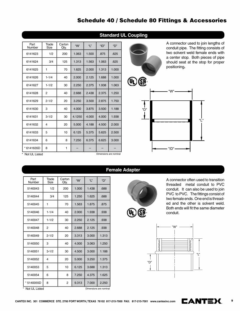
6141623 1/2 200 1.063 1.500 .875 .625
6141624 3/4 125 1.313 1.563 1.063 .625
6141625 1 70 1.625 2.000 1.313 1.000
6141626 1-1/4 40 2.000 2.125 1.688 1.000
6141627 1-1/2 30 2.250 2.375 1.938 1.063
6141628 2 40 2.688 2.438 2.375 1.250
6141629 2-1/2 20 3.250 3.500 2.875 1.750
6141630 3 40 4.000 3.875 3.500 1.188
6141631 3-1/2 30 4.1250 4.000 4.000 1.938
6141632 4 20 5.000 4.188 4.500 2.000
6141633 5 10 6.125 5.375 5.625 2.500
6141634 6 8 7.250 6.375 6.625 3.000
* 6141635D 8 1 -- -- -- --
A connector used to join lengths of conduit pipe. The fi tting consists of two solvent weld female ends with a center stop. Both pieces of pipe should seat at the stop for proper positioning.
Standard UL Coupling
* Not UL Listed
Part Number
Trade Size
Carton Qty. “W’ “L” “D”
5140043 1/2 200 1.000 1.438 .688
5140044 3/4 125 1.250 1.625 .688
5140045 1 70 1.563 1.875 .875
5140046 1-1/4 40 2.000 1.938 .938
5140047 1-1/2 30 2.250 2.125 .938
5140048 2 40 2.688 2.125 .938
5140049 2-1/2 20 3.313 3.000 1.313
5140050 3 40 4.000 3.063 1.250
5140051 3-1/2 30 4.500 3.000 1.188
5140052 4 20 5.000 3.250 1.375
5140053 5 10 6.125 3.688 1.313
5140054 6 8 7.250 4.375 1.625
* 5140055D 8 2 9.313 7.000 2.250
A connector often used to transition threaded metal conduit to PVC conduit. It can also be used to join PVC to PVC. The fi ttings consist of two female ends. One end is thread-ed and the other is solvent weld. Both ends will fi t the same diameter conduit.
"W"
"L"
"D"
Female Adapter
* Not UL Listed Dimensions are nominal
Dimensions are nominal
CANTEX INC. 301 COMMERCE STE. 2700 FORT WORTH, TEXAS 76102 817-215-7000 FAX: 817-215-7001 www.cantexinc.com 9®
Schedule 40 / Schedule 80 Fittings & Accessories
Part Number
Trade Size
Carton Qty. “W’ “L” “D”
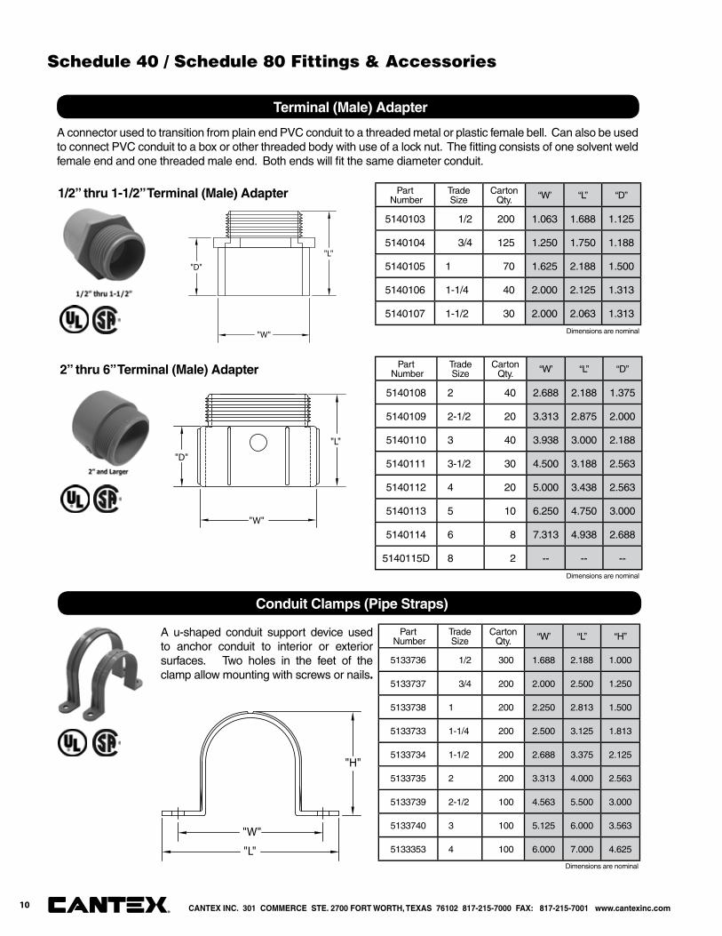
5140103 1/2 200 1.063 1.688 1.125
5140104 3/4 125 1.250 1.750 1.188
5140105 1 70 1.625 2.188 1.500
5140106 1-1/4 40 2.000 2.125 1.313
5140107 1-1/2 30 2.000 2.063 1.313
A connector used to transition from plain end PVC conduit to a threaded metal or plastic female bell. Can also be used to connect PVC conduit to a box or other threaded body with use of a lock nut. The fi tting consists of one solvent weld female end and one threaded male end. Both ends will fi t the same diameter conduit.
Terminal (Male) Adapter
"W"
"L"
"D"
Part Number
Trade Size
Carton Qty. “W’ “L” “D”
5140108 2 40 2.688 2.188 1.375
5140109 2-1/2 20 3.313 2.875 2.000
5140110 3 40 3.938 3.000 2.188
5140111 3-1/2 30 4.500 3.188 2.563
5140112 4 20 5.000 3.438 2.563
5140113 5 10 6.250 4.750 3.000
5140114 6 8 7.313 4.938 2.688
5140115D 8 2 -- -- --
"W"
"L"
"D"
1/2” thru 1-1/2” Terminal (Male) Adapter
2” thru 6” Terminal (Male) Adapter
Part Number
Trade Size
Carton Qty. “W’ “L” “H”
5133736 1/2 300 1.688 2.188 1.000
5133737 3/4 200 2.000 2.500 1.250
5133738 1 200 2.250 2.813 1.500
5133733 1-1/4 200 2.500 3.125 1.813
5133734 1-1/2 200 2.688 3.375 2.125
5133735 2 200 3.313 4.000 2.563
5133739 2-1/2 100 4.563 5.500 3.000
5133740 3 100 5.125 6.000 3.563
5133353 4 100 6.000 7.000 4.625
A u-shaped conduit support device used to anchor conduit to interior or exterior surfaces. Two holes in the feet of the clamp allow mounting with screws or nails.
Conduit Clamps (Pipe Straps)
"H"
"L"
"W"
Dimensions are nominal
Dimensions are nominal
Dimensions are nominal
CANTEX INC. 301 COMMERCE STE. 2700 FORT WORTH, TEXAS 76102 817-215-7000 FAX: 817-215-7001 www.cantexinc.com®
10
Schedule 40 / Schedule 80 Fittings & Accessories
Part Number
Trade Size
Carton Qty. “W’ “L” Travel
Length
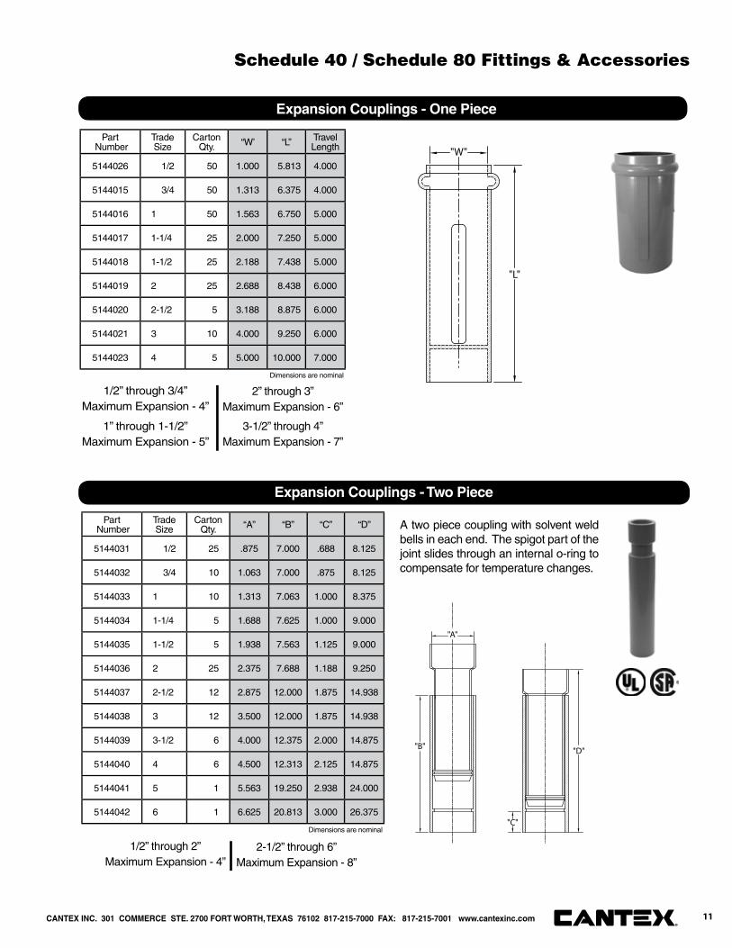
5144026 1/2 50 1.000 5.813 4.000
5144015 3/4 50 1.313 6.375 4.000
5144016 1 50 1.563 6.750 5.000
5144017 1-1/4 25 2.000 7.250 5.000
5144018 1-1/2 25 2.188 7.438 5.000
5144019 2 25 2.688 8.438 6.000
5144020 2-1/2 5 3.188 8.875 6.000
5144021 3 10 4.000 9.250 6.000
5144023 4 5 5.000 10.000 7.000
Expansion Couplings - One Piece
"L"
"W"
A two piece coupling with solvent weld bells in each end. The spigot part of the joint slides through an internal o-ring to compensate for temperature changes.
Expansion Couplings - Two Piece
"B"
"A"
"D"
"C"
Part Number
Trade Size
Carton Qty. “A” “B” “C” “D”
5144031 1/2 25 .875 7.000 .688 8.125
5144032 3/4 10 1.063 7.000 .875 8.125
5144033 1 10 1.313 7.063 1.000 8.375
5144034 1-1/4 5 1.688 7.625 1.000 9.000
5144035 1-1/2 5 1.938 7.563 1.125 9.000
5144036 2 25 2.375 7.688 1.188 9.250
5144037 2-1/2 12 2.875 12.000 1.875 14.938
5144038 3 12 3.500 12.000 1.875 14.938
5144039 3-1/2 6 4.000 12.375 2.000 14.875
5144040 4 6 4.500 12.313 2.125 14.875
5144041 5 1 5.563 19.250 2.938 24.000
5144042 6 1 6.625 20.813 3.000 26.375
1/2” through 3/4”Maximum Expansion - 4”
1” through 1-1/2”Maximum Expansion - 5”
2” through 3”Maximum Expansion - 6”
3-1/2” through 4”Maximum Expansion - 7”
1/2” through 2”Maximum Expansion - 4”
2-1/2” through 6”Maximum Expansion - 8”
Dimensions are nominal
Dimensions are nominal
CANTEX INC. 301 COMMERCE STE. 2700 FORT WORTH, TEXAS 76102 817-215-7000 FAX: 817-215-7001 www.cantexinc.com 11®
Schedule 40 / Schedule 80 Fittings & Accessories
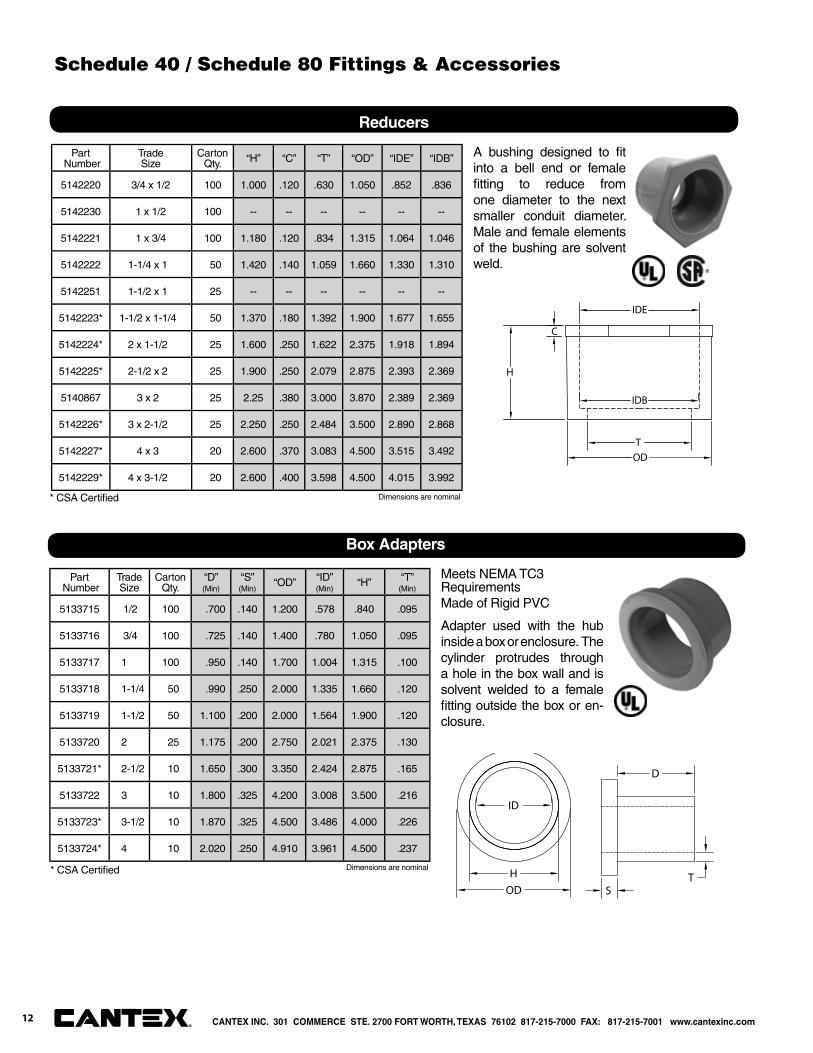
A bushing designed to fi t into a bell end or female fi tting to reduce from one diameter to the next smaller conduit diameter. Male and female elements of the bushing are solvent weld.
Reducers
T
H
C
IDE
OD
IDB
Part Number
TradeSize
Carton Qty. “H” “C” “T” “OD” “IDE” “IDB”
5142220 3/4 x 1/2 100 1.000 .120 .630 1.050 .852 .836
5142230 1 x 1/2 100 -- -- -- -- -- --
5142221 1 x 3/4 100 1.180 .120 .834 1.315 1.064 1.046
5142222 1-1/4 x 1 50 1.420 .140 1.059 1.660 1.330 1.310
5142251 1-1/2 x 1 25 -- -- -- -- -- --
5142223* 1-1/2 x 1-1/4 50 1.370 .180 1.392 1.900 1.677 1.655
5142224* 2 x 1-1/2 25 1.600 .250 1.622 2.375 1.918 1.894
5142225* 2-1/2 x 2 25 1.900 .250 2.079 2.875 2.393 2.369
5140867 3 x 2 25 2.25 .380 3.000 3.870 2.389 2.369
5142226* 3 x 2-1/2 25 2.250 .250 2.484 3.500 2.890 2.868
5142227* 4 x 3 20 2.600 .370 3.083 4.500 3.515 3.492
5142229* 4 x 3-1/2 20 2.600 .400 3.598 4.500 4.015 3.992
* CSA Certifi ed
Box Adapters
ID
HOD S
D
T
Part Number
TradeSize
Carton Qty.
“D”(Min)
“S”(Min)
“OD” “ID”(Min)
“H” “T”(Min)
5133715 1/2 100 .700 .140 1.200 .578 .840 .095
5133716 3/4 100 .725 .140 1.400 .780 1.050 .095
5133717 1 100 .950 .140 1.700 1.004 1.315 .100
5133718 1-1/4 50 .990 .250 2.000 1.335 1.660 .120
5133719 1-1/2 50 1.100 .200 2.000 1.564 1.900 .120
5133720 2 25 1.175 .200 2.750 2.021 2.375 .130
5133721* 2-1/2 10 1.650 .300 3.350 2.424 2.875 .165
5133722 3 10 1.800 .325 4.200 3.008 3.500 .216
5133723* 3-1/2 10 1.870 .325 4.500 3.486 4.000 .226
5133724* 4 10 2.020 .250 4.910 3.961 4.500 .237
* CSA Certifi ed
Dimensions are nominal
Dimensions are nominal
Meets NEMA TC3 RequirementsMade of Rigid PVC
Adapter used with the hub inside a box or enclosure. The cylinder protrudes through a hole in the box wall and is solvent welded to a female fi tting outside the box or en-closure.
CANTEX INC. 301 COMMERCE STE. 2700 FORT WORTH, TEXAS 76102 817-215-7000 FAX: 817-215-7001 www.cantexinc.com®
12
Schedule 40 / Schedule 80 Fittings & Accessories

Part Number
Trade Size
Carton Qty. “L” “ID” “OD”
5144003 1/2 100 1.000 .625 1.250
5144004 3/4 100 1.000 .875 1.500
5144005 1 50 1.250 1.063 1.750
5144006 1-1/4 50 1.313 1.375 2.125
5144007 1-1/2 50 1.563 1625 2.500
5144008 2 40 1.563 2.063 2.813
5144009 2-1/2 30 1.875 2.500 3.375
5144010 3 50 2.063 3.000 4.125
5144011 3-1/2 50 2.250 3.500 4.625
5144012 4 50 2.375 4.000 5.125
5144013 5 25 2.438 5.063 6.375
5144014 6 15 2.875 6.063 7.375
5143987 *8 1 10.000 8.063 10.375
Used in concrete vault walls to provide a smooth, safe entrance to the conduit outside. Protects wiring which is being pulled through the vault wall.
Meets requirements of NEMA TC-9
Schedule 40 End Bell
L
ODID
SIDE END
* 8 inch trade size is not UL Listed
Part Number
Trade Size
Carton Qty. “A” “B”
5140031 1/2 100 .875 .875
5140032 3/4 100 1.063 1.063
5140033 1 50 1.375 1.250
5140034 1-1/4 25 1.688 1.313
5140035 1-1/2 25 1.938 1.563
5140037 2 50 2.375 1.625
5140038 2-1/2 25 2.875 2.000
5140039 3 25 3.563 2.375
5140036 3-1/2 25 4.000 2.313
5140040 4 25 4.500 2.375
5140041 5 25 5.563 2.500
5140042 6 10 6.625 3.000
Meets NEMA TC3 RequirementsMade of Rigid PVC
End Cap
"B"
"A"
Dimensions are nominal
Dimensions are nominal
1/2” through 4” have dome top
5” and 6” have fl at top
CANTEX INC. 301 COMMERCE STE. 2700 FORT WORTH, TEXAS 76102 817-215-7000 FAX: 817-215-7001 www.cantexinc.com 13®
Schedule 40 / Schedule 80 Fittings & Accessories

Poly Plug
Ø"D-2"
"L"
Ø"D-1"Part Number
TradeSize
Carton Qty. “L” “D-1” “D-2”
5315248 2 70 3.250 1.875 2.438
5315250 3 70 3.813 2.625 3.438
5315252 4 90 4.063 3.688 4.438
5315253 5 45 3.813 4.750 5.500
5315254 6 30 3.813 5.563 6.500
Poly Plug with Pulling Eye
Ø"D-2"
"L"
Ø"D-1"Part Number
TradeSize
Carton Qty. “L” “D-1” “D-2”
5315258 2 70 3.000 2.000 2.500
5315259 2 1/2 70 3.000 2.125 2.750
5315260 3 45 3.750 2.875 3.500
5315262 4 80 3.875 3.750 4.500
5315263 5 45 3.750 4.875 5.625
5315264 6 35 3.875 5.625 6.875
Pull Elbow
"B"
"D"
"C"
"A"
"E"
Part Number
TradeSize
Carton Qty. “A” “B” “C” “D” “E”
5240100 1/2 75 2.125 2.625 1.500 .875 1.125
5240101 3/4 50 2.500 3.000 1.625 1.063 1.313
Dimensions are nominal
Dimensions are nominal
Dimensions are nominal
CANTEX INC. 301 COMMERCE STE. 2700 FORT WORTH, TEXAS 76102 817-215-7000 FAX: 817-215-7001 www.cantexinc.com®
Schedule 40 / Schedule 80 Fittings & Accessories
14
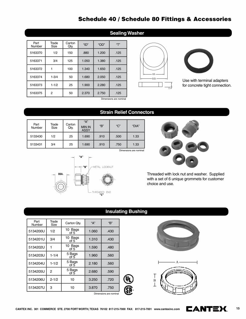
Sealing Washer
I.D.
O.D.
T
Part Number
TradeSize
Carton Qty. “ID” “OD” “T”
5163370 1/2 150 .880 1.200 .125
5163371 3/4 125 1.050 1.380 .125
5163372 1 100 1.340 1.650 .125
5163374 1-3/4 50 1.680 2.050 .125
5163373 1-1/2 25 1.900 2.280 .125
5163375 2 50 2.370 2.750 .125
Strain Relief Connectors
Part Number
TradeSize
Carton Qty.
“A”
MIN IN ASSY
“B” “C” “DIA”
5133430 1/2 25 1.690 .910 .500 1.33
5133431 3/4 25 1.690 .910 .750 1.33
Threaded with lock nut and washer. Supplied with a set of 6 unique grommets for customer choice and use.
Use with terminal adapters for concrete tight connection.
Dimensions are nominal
Dimensions are nominal
Part Number
Trade Size Carton Qty. “A” “B”
5134200U 1/2 10 Bags of 5 1.060 .430
5134201U 3/4 10 Bags of 5 1.310 .430
5134202U 1 10 Bags of 5 1.590 .480
5134203U 1-1/4 5 Bags of 5 1.960 .560
5134204U 1-1/2 5 Bags of 5 2.180 .560
5134205U 2 5 Bags of 5 2.680 .590
5134206U 2-1/2 10 3.250 .720
5134207U 3 10 3.870 .750
Insulating Bushing
A
B
Dimensions are nominal
CANTEX INC. 301 COMMERCE STE. 2700 FORT WORTH, TEXAS 76102 817-215-7000 FAX: 817-215-7001 www.cantexinc.com 15®
Schedule 40 / Schedule 80 Fittings & Accessories
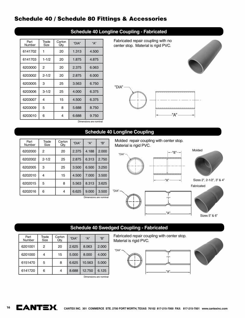
Part Number
Trade Size
Carton Qty. “DIA” “A”
6141702 1 20 1.313 4.500
6141703 1-1/2 20 1.875 4.875
6203000 2 20 2.375 6.063
6203002 2-1/2 20 2.875 6.000
6203005 3 25 3.563 6.750
6203006 3-1/2 25 4.000 6.375
6203007 4 15 4.500 6.375
6203009 5 8 5.688 8.750
6203010 6 4 6.688 9.750
Fabricated repair coupling with no center stop. Material is rigid PVC.
Schedule 40 Longline Coupling - Fabricated
"DIA"
"A"
Part Number
Trade Size
Carton Qty. “DIA” “A” “B”
6202000 2 20 2.375 4.188 2.000
6202002 2-1/2 25 2.875 6.313 2.750
6202005 3 25 3.500 6.500 3.250
6202010 4 15 4.500 7.000 3.500
6202015 5 8 5.563 8.313 3.625
6202016 6 4 6.625 9.000 3.500
Schedule 40 Longline Coupling
"DIA"
"A"
"B"
Part Number
Trade Size
Carton Qty. “DIA” “A” “B”
6201001 2 20 2.625 8.063 2.000
6201000 4 15 5.000 8.000 4.000
6151470 5 8 6.625 10.563 5.000
6141720 6 4 8.688 12.750 6.125
Fabricated repair coupling with center stop. Material is rigid PVC.
Schedule 40 Swedged Coupling - Fabricated
"A"
“T”
"DIA"
Molded repair coupling with center stop. Material is rigid PVC.
Sizes 2”, 2-1/2”, 3” & 4”
"A"
“T”
"DIA"
Sizes 5” & 6”
Dimensions are nominal
Dimensions are nominal
Dimensions are nominal
Molded
Fabricated
CANTEX INC. 301 COMMERCE STE. 2700 FORT WORTH, TEXAS 76102 817-215-7000 FAX: 817-215-7001 www.cantexinc.com®
Schedule 40 / Schedule 80 Fittings & Accessories
16
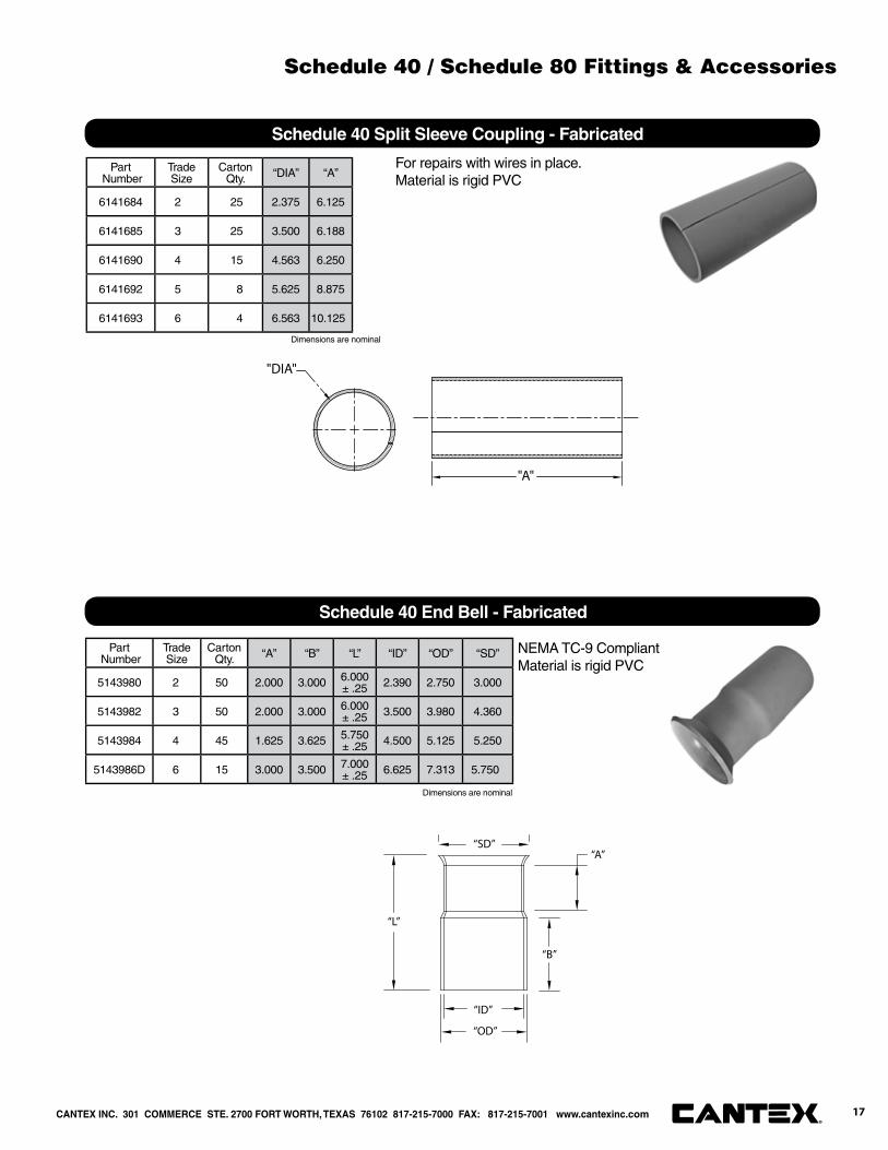
Part Number
Trade Size
Carton Qty. “DIA” “A”
6141684 2 25 2.375 6.125
6141685 3 25 3.500 6.188
6141690 4 15 4.563 6.250
6141692 5 8 5.625 8.875
6141693 6 4 6.563 10.125
For repairs with wires in place. Material is rigid PVC
Schedule 40 Split Sleeve Coupling - Fabricated
"DIA"
"A"
Part Number
Trade Size
Carton Qty. “A” “B” “L” “ID” “OD” “SD”
5143980 2 50 2.000 3.000 6.000± .25 2.390 2.750 3.000
5143982 3 50 2.000 3.000 6.000± .25 3.500 3.980 4.360
5143984 4 45 1.625 3.625 5.750± .25 4.500 5.125 5.250
5143986D 6 15 3.000 3.500 7.000± .25 6.625 7.313 5.750
NEMA TC-9 CompliantMaterial is rigid PVC
Schedule 40 End Bell - Fabricated
“L”
“A”
“B”
“SD”
“ID”
“OD”
Dimensions are nominal
Dimensions are nominal
CANTEX INC. 301 COMMERCE STE. 2700 FORT WORTH, TEXAS 76102 817-215-7000 FAX: 817-215-7001 www.cantexinc.com 17®
Schedule 40 / Schedule 80 Fittings & Accessories
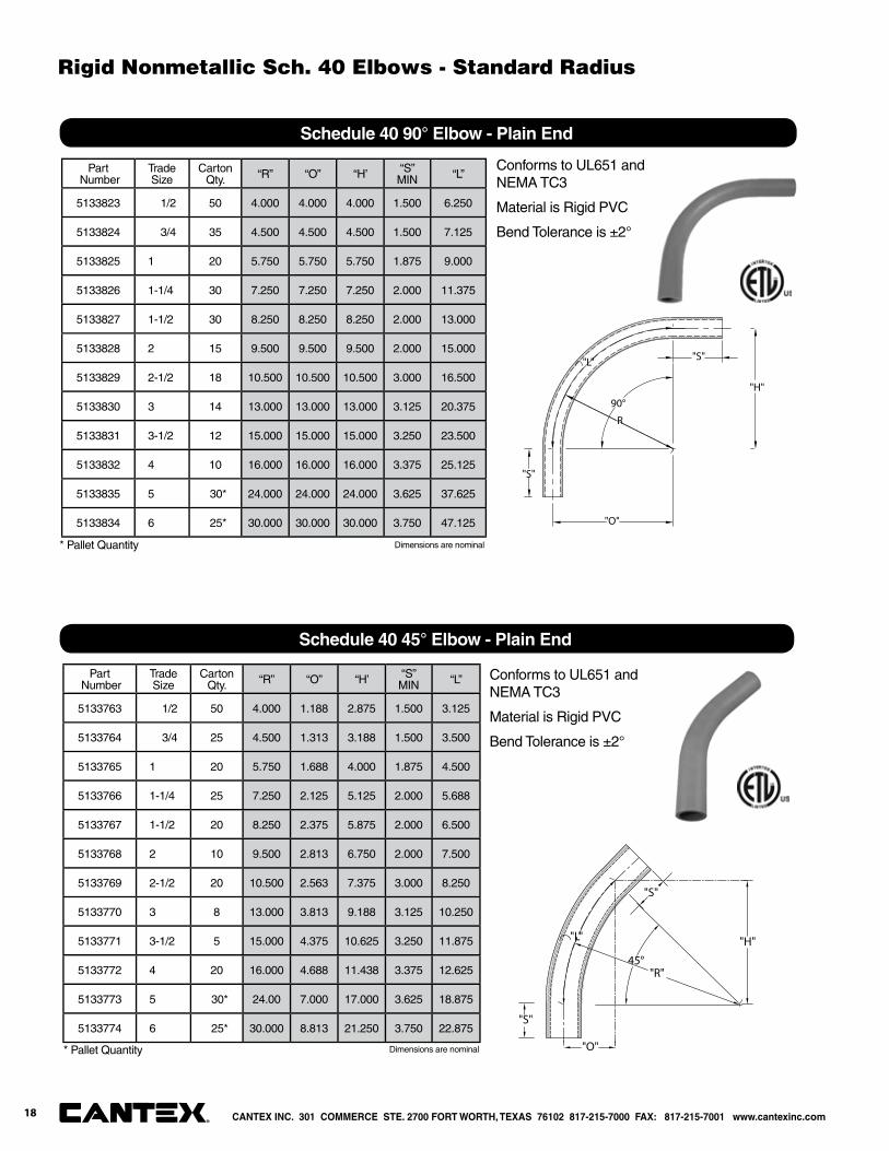
Part Number
Trade Size
Carton Qty. “R” “O” “H’ “S”
MIN “L”
5133823 1/2 50 4.000 4.000 4.000 1.500 6.250
5133824 3/4 35 4.500 4.500 4.500 1.500 7.125
5133825 1 20 5.750 5.750 5.750 1.875 9.000
5133826 1-1/4 30 7.250 7.250 7.250 2.000 11.375
5133827 1-1/2 30 8.250 8.250 8.250 2.000 13.000
5133828 2 15 9.500 9.500 9.500 2.000 15.000
5133829 2-1/2 18 10.500 10.500 10.500 3.000 16.500
5133830 3 14 13.000 13.000 13.000 3.125 20.375
5133831 3-1/2 12 15.000 15.000 15.000 3.250 23.500
5133832 4 10 16.000 16.000 16.000 3.375 25.125
5133835 5 30* 24.000 24.000 24.000 3.625 37.625
5133834 6 25* 30.000 30.000 30.000 3.750 47.125
90°
"O"
"S"
R
"H"
"S"
"L"
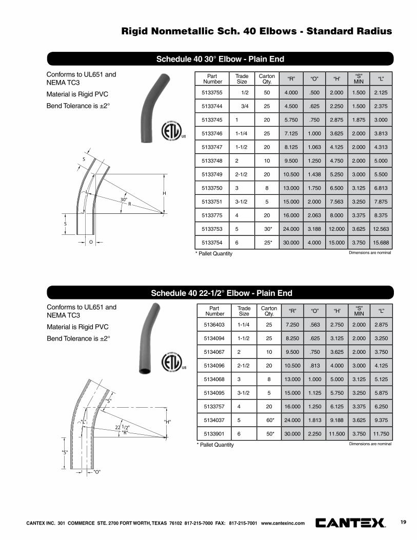
Conforms to UL651 and NEMA TC3
Material is Rigid PVC
Bend Tolerance is ±2°
Schedule 40 90° Elbow - Plain End
Part Number
Trade Size
Carton Qty. “R” “O” “H’ “S”
MIN “L”
5133763 1/2 50 4.000 1.188 2.875 1.500 3.125
5133764 3/4 25 4.500 1.313 3.188 1.500 3.500
5133765 1 20 5.750 1.688 4.000 1.875 4.500
5133766 1-1/4 25 7.250 2.125 5.125 2.000 5.688
5133767 1-1/2 20 8.250 2.375 5.875 2.000 6.500
5133768 2 10 9.500 2.813 6.750 2.000 7.500
5133769 2-1/2 20 10.500 2.563 7.375 3.000 8.250
5133770 3 8 13.000 3.813 9.188 3.125 10.250
5133771 3-1/2 5 15.000 4.375 10.625 3.250 11.875
5133772 4 20 16.000 4.688 11.438 3.375 12.625
5133773 5 30* 24.00 7.000 17.000 3.625 18.875
5133774 6 25* 30.000 8.813 21.250 3.750 22.875
"S"
45°
"S"
"L"
"O"
"H"
"R"
Conforms to UL651 and NEMA TC3
Material is Rigid PVC
Bend Tolerance is ±2°
Schedule 40 45° Elbow - Plain End
* Pallet Quantity
* Pallet Quantity
Dimensions are nominal
Dimensions are nominal
CANTEX INC. 301 COMMERCE STE. 2700 FORT WORTH, TEXAS 76102 817-215-7000 FAX: 817-215-7001 www.cantexinc.com®
Rigid Nonmetallic Sch. 40 Elbows - Standard Radius
18
Part Number
Trade Size
Carton Qty. “R” “O” “H’ “S”
MIN “L”
5133755 1/2 50 4.000 .500 2.000 1.500 2.125
5133744 3/4 25 4.500 .625 2.250 1.500 2.375
5133745 1 20 5.750 .750 2.875 1.875 3.000
5133746 1-1/4 25 7.125 1.000 3.625 2.000 3.813
5133747 1-1/2 20 8.125 1.063 4.125 2.000 4.313
5133748 2 10 9.500 1.250 4.750 2.000 5.000
5133749 2-1/2 20 10.500 1.438 5.250 3.000 5.500
5133750 3 8 13.000 1.750 6.500 3.125 6.813
5133751 3-1/2 5 15.000 2.000 7.563 3.250 7.875
5133775 4 20 16.000 2.063 8.000 3.375 8.375
5133753 5 30* 24.000 3.188 12.000 3.625 12.563
5133754 6 25* 30.000 4.000 15.000 3.750 15.688
30°
S
R
L H
S
O
Conforms to UL651 and NEMA TC3
Material is Rigid PVC
Bend Tolerance is ±2°
Schedule 40 30° Elbow - Plain End
Part Number
Trade Size
Carton Qty. “R” “O” “H’ “S”
MIN “L”
5136403 1-1/4 25 7.250 .563 2.750 2.000 2.875
5134094 1-1/2 25 8.250 .625 3.125 2.000 3.250
5134067 2 10 9.500 .750 3.625 2.000 3.750
5134096 2-1/2 20 10.500 .813 4.000 3.000 4.125
5134068 3 8 13.000 1.000 5.000 3.125 5.125
5134095 3-1/2 5 15.000 1.125 5.750 3.250 5.875
5133757 4 20 16.000 1.250 6.125 3.375 6.250
5134037 5 60* 24.000 1.813 9.188 3.625 9.375
5133901 6 50* 30.000 2.250 11.500 3.750 11.75022 1/2°
"L"
"S"
"S"
"R"
"H"
"O"
Conforms to UL651 and NEMA TC3
Material is Rigid PVC
Bend Tolerance is ±2°
Schedule 40 22-1/2° Elbow - Plain End
* Pallet Quantity
* Pallet Quantity Dimensions are nominal
Dimensions are nominal
CANTEX INC. 301 COMMERCE STE. 2700 FORT WORTH, TEXAS 76102 817-215-7000 FAX: 817-215-7001 www.cantexinc.com 19®
Rigid Nonmetallic Sch. 40 Elbows - Standard Radius
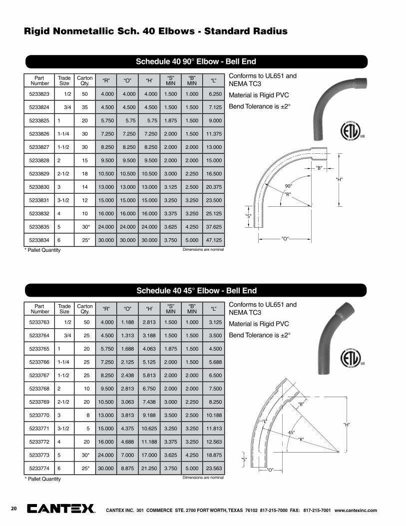
Part Number
Trade Size
Carton Qty. “R” “O” “H’ “S”
MIN“B”MIN “L”
5233823 1/2 50 4.000 4.000 4.000 1.500 1.000 6.250
5233824 3/4 35 4.500 4.500 4.500 1.500 1.500 7.125
5233825 1 20 5.750 5.75 5.75 1.875 1.500 9.000
5233826 1-1/4 30 7.250 7.250 7.250 2.000 1.500 11.375
5233827 1-1/2 30 8.250 8.250 8.250 2.000 2.000 13.000
5233828 2 15 9.500 9.500 9.500 2.000 2.000 15.000
5233829 2-1/2 18 10.500 10.500 10.500 3.000 2.250 16.500
5233830 3 14 13.000 13.000 13.000 3.125 2.500 20.375
5233831 3-1/2 12 15.000 15.000 15.000 3.250 3.250 23.500
5233832 4 10 16.000 16.000 16.000 3.375 3.250 25.125
5233835 5 30* 24.000 24.000 24.000 3.625 4.250 37.625
5233834 6 25* 30.000 30.000 30.000 3.750 5.000 47.125
90°
"O"
"B"
"R"
"S"
"H"
Conforms to UL651 and NEMA TC3
Material is Rigid PVC
Bend Tolerance is ±2°
Schedule 40 90° Elbow - Bell End
45°
"B"
"O"
"H""L"
"S"
"R"
Conforms to UL651 and NEMA TC3
Material is Rigid PVC
Bend Tolerance is ±2°
Schedule 40 45° Elbow - Bell End
Part Number
Trade Size
Carton Qty. “R” “O” “H’ “S”
MIN“B”MIN “L”
5233763 1/2 50 4.000 1.188 2.813 1.500 1.000 3.125
5233764 3/4 25 4.500 1.313 3.188 1.500 1.500 3.500
5233765 1 20 5.750 1.688 4.063 1.875 1.500 4.500
5233766 1-1/4 25 7.250 2.125 5.125 2.000 1.500 5.688
5233767 1-1/2 25 8.250 2.438 5.813 2.000 2.000 6.500
5233768 2 10 9.500 2.813 6.750 2.000 2.000 7.500
5233769 2-1/2 20 10.500 3.063 7.438 3.000 2.250 8.250
5233770 3 8 13.000 3.813 9.188 3.500 2.500 10.188
5233771 3-1/2 5 15.000 4.375 10.625 3.250 3.250 11.813
5233772 4 20 16.000 4.688 11.188 3.375 3.250 12.563
5233773 5 30* 24.000 7.000 17.000 3.625 4.250 18.875
5233774 6 25* 30.000 8.875 21.250 3.750 5.000 23.563
* Pallet Quantity
* Pallet Quantity
Dimensions are nominal
Dimensions are nominal
CANTEX INC. 301 COMMERCE STE. 2700 FORT WORTH, TEXAS 76102 817-215-7000 FAX: 817-215-7001 www.cantexinc.com®
Rigid Nonmetallic Sch. 40 Elbows - Standard Radius
20
30°
B
L
S
R
O
H
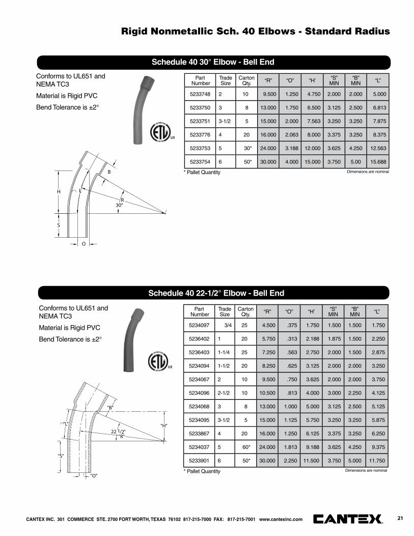
Conforms to UL651 and NEMA TC3
Material is Rigid PVC
Bend Tolerance is ±2°
Schedule 40 30° Elbow - Bell End
22 1/2°
"B"
"L"
"S"
"H"
"O"
"R"
Conforms to UL651 and NEMA TC3
Material is Rigid PVC
Bend Tolerance is ±2°
Schedule 40 22-1/2° Elbow - Bell End
Part Number
Trade Size
Carton Qty. “R” “O” “H’ “S”
MIN“B”MIN “L”
5233748 2 10 9.500 1.250 4.750 2.000 2.000 5.000
5233750 3 8 13.000 1.750 6.500 3.125 2.500 6.813
5233751 3-1/2 5 15.000 2.000 7.563 3.250 3.250 7.875
5233776 4 20 16.000 2.063 8.000 3.375 3.250 8.375
5233753 5 30* 24.000 3.188 12.000 3.625 4.250 12.563
5233754 6 50* 30.000 4.000 15.000 3.750 5.00 15.688
Part Number
Trade Size
Carton Qty. “R” “O” “H’ “S”
MIN“B”MIN “L”
5234097 3/4 25 4.500 .375 1.750 1.500 1.500 1.750
5236402 1 20 5.750 .313 2.188 1.875 1.500 2.250
5236403 1-1/4 25 7.250 .563 2.750 2.000 1.500 2.875
5234094 1-1/2 20 8.250 .625 3.125 2.000 2.000 3.250
5234067 2 10 9.500 .750 3.625 2.000 2.000 3.750
5234096 2-1/2 10 10.500 .813 4.000 3.000 2.250 4.125
5234068 3 8 13.000 1.000 5.000 3.125 2.500 5.125
5234095 3-1/2 5 15.000 1.125 5.750 3.250 3.250 5.875
5233867 4 20 16.000 1.250 6.125 3.375 3.250 6.250
5234037 5 60* 24.000 1.813 9.188 3.625 4.250 9.375
5233901 6 50* 30.000 2.250 11.500 3.750 5.000 11.750
* Pallet Quantity
* Pallet Quantity
Dimensions are nominal
Dimensions are nominal
CANTEX INC. 301 COMMERCE STE. 2700 FORT WORTH, TEXAS 76102 817-215-7000 FAX: 817-215-7001 www.cantexinc.com 21®
Rigid Nonmetallic Sch. 40 Elbows - Standard Radius
90°
"O"
"S"
R
"H"
"S"
"L"
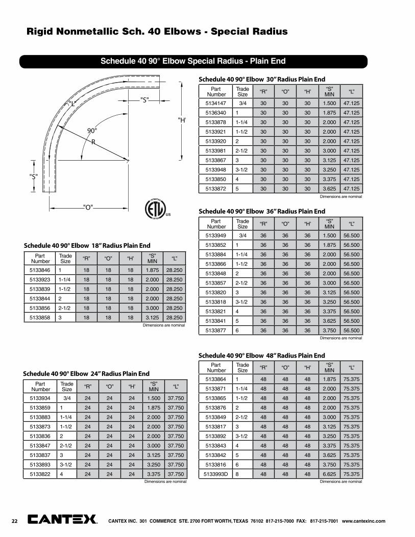
Schedule 40 90° Elbow Special Radius - Plain End
Part Number
Trade Size “R” “O” “H’ “S”
MIN “L”
5133846 1 18 18 18 1.875 28.250
5133923 1-1/4 18 18 18 2.000 28.250
5133839 1-1/2 18 18 18 2.000 28.250
5133844 2 18 18 18 2.000 28.250
5133856 2-1/2 18 18 18 3.000 28.250
5133858 3 18 18 18 3.125 28.250
Schedule 40 90° Elbow 18” Radius Plain End
Part Number
Trade Size “R” “O” “H’ “S”
MIN “L”
5133934 3/4 24 24 24 1.500 37.750
5133859 1 24 24 24 1.875 37.750
5133883 1-1/4 24 24 24 2.000 37.750
5133873 1-1/2 24 24 24 2.000 37.750
5133836 2 24 24 24 2.000 37.750
5133847 2-1/2 24 24 24 3.000 37.750
5133837 3 24 24 24 3.125 37.750
5133893 3-1/2 24 24 24 3.250 37.750
5133822 4 24 24 24 3.375 37.750
Schedule 40 90° Elbow 24” Radius Plain End
Part Number
Trade Size “R” “O” “H’ “S”
MIN “L”
5134147 3/4 30 30 30 1.500 47.125
5136340 1 30 30 30 1.875 47.125
5133878 1-1/4 30 30 30 2.000 47.125
5133921 1-1/2 30 30 30 2.000 47.125
5133920 2 30 30 30 2.000 47.125
5133981 2-1/2 30 30 30 3.000 47.125
5133867 3 30 30 30 3.125 47.125
5133948 3-1/2 30 30 30 3.250 47.125
5133850 4 30 30 30 3.375 47.125
5133872 5 30 30 30 3.625 47.125
Schedule 40 90° Elbow 30” Radius Plain End
Part Number
Trade Size “R” “O” “H’ “S”
MIN “L”
5133949 3/4 36 36 36 1.500 56.500
5133852 1 36 36 36 1.875 56.500
5133884 1-1/4 36 36 36 2.000 56.500
5133866 1-1/2 36 36 36 2.000 56.500
5133848 2 36 36 36 2.000 56.500
5133857 2-1/2 36 36 36 3.000 56.500
5133820 3 36 36 36 3.125 56.500
5133818 3-1/2 36 36 36 3.250 56.500
5133821 4 36 36 36 3.375 56.500
5133841 5 36 36 36 3.625 56.500
5133877 6 36 36 36 3.750 56.500
Schedule 40 90° Elbow 36” Radius Plain End
Part Number
Trade Size “R” “O” “H’ “S”
MIN “L”
5133864 1 48 48 48 1.875 75.375
5133871 1-1/4 48 48 48 2.000 75.375
5133865 1-1/2 48 48 48 2.000 75.375
5133876 2 48 48 48 2.000 75.375
5133849 2-1/2 48 48 48 3.000 75.375
5133817 3 48 48 48 3.125 75.375
5133892 3-1/2 48 48 48 3.250 75.375
5133843 4 48 48 48 3.375 75.375
5133842 5 48 48 48 3.625 75.375
5133816 6 48 48 48 3.750 75.375
5133993D 8 48 48 48 6.625 75.375
Schedule 40 90° Elbow 48” Radius Plain End
Dimensions are nominal
Dimensions are nominal
Dimensions are nominal
Dimensions are nominal
Dimensions are nominal
CANTEX INC. 301 COMMERCE STE. 2700 FORT WORTH, TEXAS 76102 817-215-7000 FAX: 817-215-7001 www.cantexinc.com®
Rigid Nonmetallic Sch. 40 Elbows - Special Radius
22
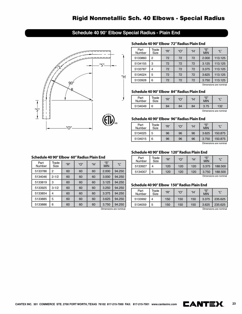
Schedule 40 90° Elbow Special Radius - Plain End
90°
"O"
"S"
R
"H"
"S"
"L"
Part Number
Trade Size “R” “O” “H’ “S”
MIN “L”
5133786 2 60 60 60 2.000 94.250
5134046 2-1/2 60 60 60 3.000 94.250
5133819 3 60 60 60 3.125 94.250
5133925 3-1/2 60 60 60 3.250 94.250
5133854 4 60 60 60 3.375 94.250
5133885 5 60 60 60 3.625 94.250
5133886 6 60 60 60 3.750 94.250
Schedule 40 90° Elbow 60” Radius Plain End
Part Number
Trade Size “R” “O” “H’ “S”
MIN “L”
5133860 2 72 72 72 2.000 113.125
5134155 3 72 72 72 3.125 113.125
5133787 4 72 72 72 3.375 113.125
5134024 5 72 72 72 3.625 113.125
5133928 6 72 72 72 3.750 113.125
Schedule 40 90° Elbow 72” Radius Plain End
Part Number
Trade Size “R” “O” “H’ “S”
MIN “L”
5134049 6 84 84 84 3.75 132
Schedule 40 90° Elbow 84” Radius Plain End
Part Number
Trade Size “R” “O” “H’ “S”
MIN “L”
5134025 5 96 96 96 3.625 150.875
5134015 6 96 96 96 3.750 150.875
Schedule 40 90° Elbow 96” Radius Plain End
Part Number
Trade Size “R” “O” “H’ “S”
MIN “L”
5133927 4 120 120 120 3.375 188.500
5134007 6 120 120 120 3.750 188.500
Schedule 40 90° Elbow 120” Radius Plain End
Part Number
Trade Size “R” “O” “H’ “S”
MIN “L”
5133992 4 150 150 150 3.375 235.625
5134059 5 150 150 150 3.625 235.625
Schedule 40 90° Elbow 150” Radius Plain End
Dimensions are nominal
Dimensions are nominal
Dimensions are nominal
Dimensions are nominal
Dimensions are nominal Dimensions are nominal
CANTEX INC. 301 COMMERCE STE. 2700 FORT WORTH, TEXAS 76102 817-215-7000 FAX: 817-215-7001 www.cantexinc.com 23®
Rigid Nonmetallic Sch. 40 Elbows - Special Radius
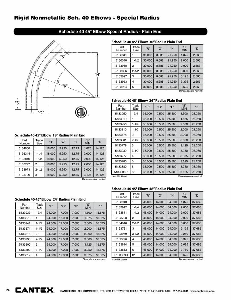
Schedule 40 45° Elbow Special Radius - Plain End
"S"
45°
"S"
"L"
"O"
"H"
"R"
Part Number
Trade Size “R” “O” “H’ “S”
MIN “L”
5134008 1 18.000 5.250 12.75 1.875 14.125
5136344 1-1/4 18.000 5.250 12.75 2.000 14.125
5133840 1-1/2 18.000 5.250 12.75 2.000 14.125
5133797 2 18.000 5.250 12.75 2.000 14.125
5133973 2-1/2 18.000 5.250 12.75 3.000 14.125
5133799 3 18.000 5.250 12.75 3.125 14.125
Schedule 40 45° Elbow 18” Radius Plain End
Part Number
Trade Size “R” “O” “H’ “S”
MIN “L”
5133933 3/4 24.000 17.000 7.000 1.500 18.875
5133875 1 24.000 17.000 7.000 1.875 18.875
5133941 1-1/4 24.000 17.000 7.000 2.000 18.875
5133874 1-1/2 24.000 17.000 7.000 2.000 18.875
5133815 2 24.000 17.000 7.000 2.000 18.875
5133935 2-1/2 24.000 17.000 7.000 3.000 18.875
5133800 3 24.000 17.000 7.000 3.125 18.875
5133802 3-1/2 24.000 17.000 7.000 3.250 18.875
5133812 4 24.000 17.000 7.000 3.375 18.875
Schedule 40 45° Elbow 24” Radius Plain End
Part Number
Trade Size “R” “O” “H’ “S”
MIN “L”
5136341 1 30.000 8.688 21.250 1.875 2.563
5136348 1-1/2 30.000 8.688 21.250 2.000 2.563
5133918 2 30.000 8.688 21.250 2.000 2.563
5133896 2-1/2 30.000 8.688 21.250 3.000 2.563
5133897 3 30.000 8.688 21.250 3.125 2.563
5133953 4 30.000 8.688 21.250 3.375 2.563
5133954 5 30.000 8.688 21.250 3.625 2.563
Schedule 40 45° Elbow 30” Radius Plain End
Part Number
Trade Size “R” “O” “H’ “S”
MIN “L”
5133950 3/4 36.000 10.500 25.500 1.500 28.250
5133919 1 36.000 10.500 25.500 1.875 28.250
5133956 1-1/4 36.000 10.500 25.500 2.000 28.250
5133810 1-1/2 36.000 10.500 25.500 2.000 28.250
5133778 2 36.000 10.500 25.500 2.000 28.250
5133801 2-1/2 36.000 10.500 25.500 3.000 28.250
5133779 3 36.000 10.500 25.500 3.125 28.250
5133939 3-1/2 36.000 10.500 25.500 3.250 28.250
5133777 4 36.000 10.500 25.500 3.375 28.250
5133780 5 36.000 10.500 25.500 3.625 28.250
5133880 6 36.000 10.500 25.500 3.750 28.250
5133988D 8* 36.000 10.500 25.500 6.625 28.250
Schedule 40 45° Elbow 36” Radius Plain End
Dimensions are nominal
Dimensions are nominal
Dimensions are nominal
Dimensions are nominal
Part Number
Trade Size “R” “O” “H’ “S”
MIN “L”
5133940 1 48.000 14.000 34.000 1.875 37.688
5133942 1-1/4 48.000 14.000 34.000 2.000 37.688
5133811 1-1/2 48.000 14.000 34.000 2.000 37.688
5133798 2 48.000 14.000 34.000 2.000 37.688
5134010 2-1/2 48.000 14.000 34.000 3.000 37.688
5133781 3 48.000 14.000 34.000 3.125 37.688
5133979 3-1/2 48.000 14.000 34.000 3.250 37.688
5133776 4 48.000 14.000 34.000 3.375 37.688
5133814 5 48.000 14.000 34.000 3.625 37.688
5133813 6 48.000 14.000 34.000 3.750 37.688
5133989D 8* 48.000 14.000 34.000 6.625 37.688
Schedule 40 45° Elbow 48” Radius Plain End
Dimensions are nominal
*Not ETL Listed
*Not ETL Listed
CANTEX INC. 301 COMMERCE STE. 2700 FORT WORTH, TEXAS 76102 817-215-7000 FAX: 817-215-7001 www.cantexinc.com®
Rigid Nonmetallic Sch. 40 Elbows - Special Radius
24

Schedule 40 45° Elbow Special Radius - Plain End
"S"
45°
"S"
"L"
"O"
"H"
"R"
Part Number
Trade Size “R” “O” “H’ “S”
MIN “L”
5134128 3 72.000 21.000 50.938 3.125 56.500
5134153 5 72.000 21.000 50.938 3.625 56.500
5133868 6 72.000 21.000 50.938 3.750 56.500
Schedule 40 45° Elbow 72” Radius Plain End
Part Number
Trade Size “R” “O” “H’ “S”
MIN “L”
5133783 4 84.000 24.625 59.375 3.375 66.000
Schedule 40 45° Elbow 84” Radius Plain End
Part Number
Trade Size “R” “O” “H’ “S”
MIN “L”
5133785 4 96.000 28.125 67.875 3.375 75.375
5134027 5 96.000 28.125 67.875 3.625 75.375
5134086 6 96.000 28.125 67.875 3.750 75.375
5134100 8 96.000 28.125 67.875 6.625 75.375
Schedule 40 45° Elbow 96” Radius Plain End
Part Number
Trade Size “R” “O” “H’ “S”
MIN “L”
5125886 4 120.000 35.188 84.875 3.375 94.250
Schedule 40 45° Elbow 120” Radius Plain End
Dimensions are nominal
Dimensions are nominal
Dimensions are nominal
Dimensions are nominal
Part Number
Trade Size “R” “O” “H’ “S”
MIN “L”
5133808 2 60.000 17.625 34.000 2.000 47.125
5134111 2-1/2 60.000 17.625 34.000 3.000 47.125
5134006 3 60.000 17.625 34.000 3.125 47.125
5133946 4 60.000 17.625 34.000 3.375 47.125
5133947 5 60.000 17.625 34.000 3.625 47.125
5133806 6 60.000 17.625 34.000 6.750 47.125
5133980 8 60.000 17.625 34.000 6.625 47.125
Schedule 40 45° Elbow 60” Radius Plain End
Dimensions are nominal
CANTEX INC. 301 COMMERCE STE. 2700 FORT WORTH, TEXAS 76102 817-215-7000 FAX: 817-215-7001 www.cantexinc.com 25®
Rigid Nonmetallic Sch. 40 Elbows - Special Radius
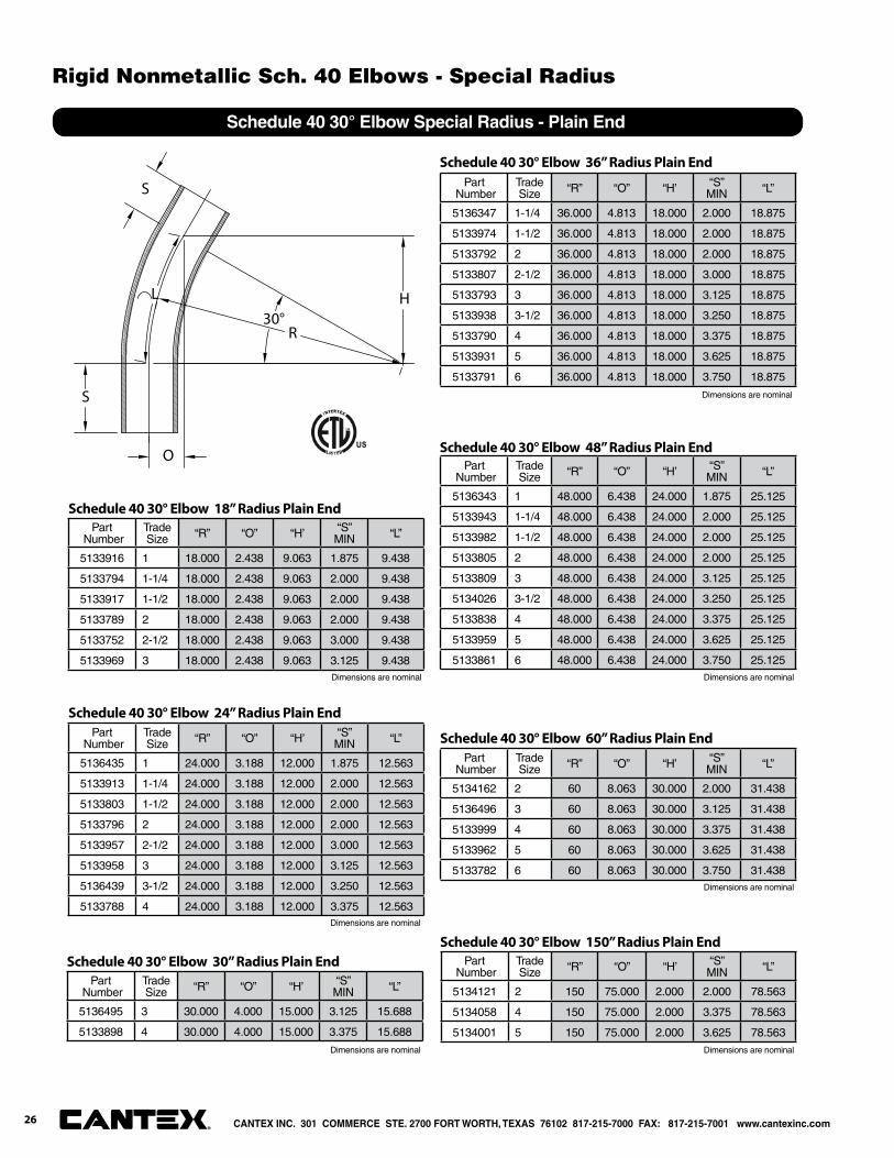
Schedule 40 30° Elbow Special Radius - Plain End
30°
S
R
L H
S
O
Part Number
Trade Size “R” “O” “H’ “S”
MIN “L”
5133916 1 18.000 2.438 9.063 1.875 9.438
5133794 1-1/4 18.000 2.438 9.063 2.000 9.438
5133917 1-1/2 18.000 2.438 9.063 2.000 9.438
5133789 2 18.000 2.438 9.063 2.000 9.438
5133752 2-1/2 18.000 2.438 9.063 3.000 9.438
5133969 3 18.000 2.438 9.063 3.125 9.438
Schedule 40 30° Elbow 18” Radius Plain End
Part Number
Trade Size “R” “O” “H’ “S”
MIN “L”
5136435 1 24.000 3.188 12.000 1.875 12.563
5133913 1-1/4 24.000 3.188 12.000 2.000 12.563
5133803 1-1/2 24.000 3.188 12.000 2.000 12.563
5133796 2 24.000 3.188 12.000 2.000 12.563
5133957 2-1/2 24.000 3.188 12.000 3.000 12.563
5133958 3 24.000 3.188 12.000 3.125 12.563
5136439 3-1/2 24.000 3.188 12.000 3.250 12.563
5133788 4 24.000 3.188 12.000 3.375 12.563
Schedule 40 30° Elbow 24” Radius Plain End
Part Number
Trade Size “R” “O” “H’ “S”
MIN “L”
5136495 3 30.000 4.000 15.000 3.125 15.688
5133898 4 30.000 4.000 15.000 3.375 15.688
Schedule 40 30° Elbow 30” Radius Plain End
Part Number
Trade Size “R” “O” “H’ “S”
MIN “L”
5136347 1-1/4 36.000 4.813 18.000 2.000 18.875
5133974 1-1/2 36.000 4.813 18.000 2.000 18.875
5133792 2 36.000 4.813 18.000 2.000 18.875
5133807 2-1/2 36.000 4.813 18.000 3.000 18.875
5133793 3 36.000 4.813 18.000 3.125 18.875
5133938 3-1/2 36.000 4.813 18.000 3.250 18.875
5133790 4 36.000 4.813 18.000 3.375 18.875
5133931 5 36.000 4.813 18.000 3.625 18.875
5133791 6 36.000 4.813 18.000 3.750 18.875
Schedule 40 30° Elbow 36” Radius Plain End
Part Number
Trade Size “R” “O” “H’ “S”
MIN “L”
5136343 1 48.000 6.438 24.000 1.875 25.125
5133943 1-1/4 48.000 6.438 24.000 2.000 25.125
5133982 1-1/2 48.000 6.438 24.000 2.000 25.125
5133805 2 48.000 6.438 24.000 2.000 25.125
5133809 3 48.000 6.438 24.000 3.125 25.125
5134026 3-1/2 48.000 6.438 24.000 3.250 25.125
5133838 4 48.000 6.438 24.000 3.375 25.125
5133959 5 48.000 6.438 24.000 3.625 25.125
5133861 6 48.000 6.438 24.000 3.750 25.125
Schedule 40 30° Elbow 48” Radius Plain End
Part Number
Trade Size “R” “O” “H’ “S”
MIN “L”
5134162 2 60 8.063 30.000 2.000 31.438
5136496 3 60 8.063 30.000 3.125 31.438
5133999 4 60 8.063 30.000 3.375 31.438
5133962 5 60 8.063 30.000 3.625 31.438
5133782 6 60 8.063 30.000 3.750 31.438
Schedule 40 30° Elbow 60” Radius Plain End
Part Number
Trade Size “R” “O” “H’ “S”
MIN “L”
5134121 2 150 75.000 2.000 2.000 78.563
5134058 4 150 75.000 2.000 3.375 78.563
5134001 5 150 75.000 2.000 3.625 78.563
Schedule 40 30° Elbow 150” Radius Plain End
Dimensions are nominal
Dimensions are nominal
Dimensions are nominal
Dimensions are nominal Dimensions are nominal
Dimensions are nominal
Dimensions are nominal
CANTEX INC. 301 COMMERCE STE. 2700 FORT WORTH, TEXAS 76102 817-215-7000 FAX: 817-215-7001 www.cantexinc.com®
Rigid Nonmetallic Sch. 40 Elbows - Special Radius
26
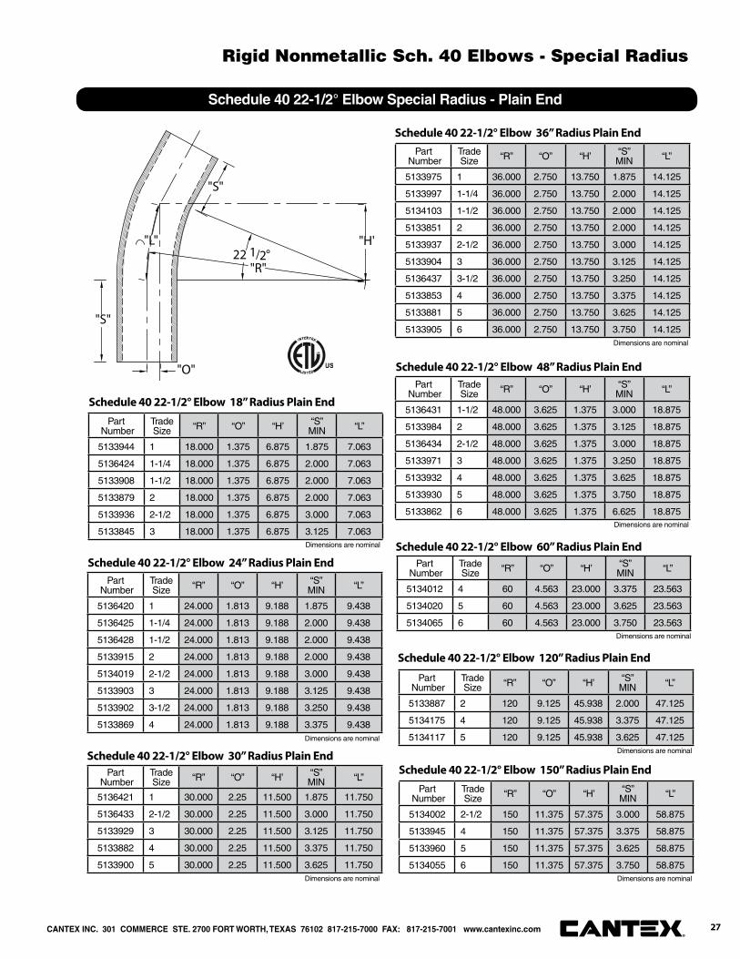
Schedule 40 22-1/2° Elbow Special Radius - Plain End
22 1/2°"L"
"S"
"S"
"R"
"H"
"O"
Part Number
Trade Size “R” “O” “H’ “S”
MIN “L”
5133944 1 18.000 1.375 6.875 1.875 7.063
5136424 1-1/4 18.000 1.375 6.875 2.000 7.063
5133908 1-1/2 18.000 1.375 6.875 2.000 7.063
5133879 2 18.000 1.375 6.875 2.000 7.063
5133936 2-1/2 18.000 1.375 6.875 3.000 7.063
5133845 3 18.000 1.375 6.875 3.125 7.063
Schedule 40 22-1/2° Elbow 18” Radius Plain End
Part Number
Trade Size “R” “O” “H’ “S”
MIN “L”
5133975 1 36.000 2.750 13.750 1.875 14.125
5133997 1-1/4 36.000 2.750 13.750 2.000 14.125
5134103 1-1/2 36.000 2.750 13.750 2.000 14.125
5133851 2 36.000 2.750 13.750 2.000 14.125
5133937 2-1/2 36.000 2.750 13.750 3.000 14.125
5133904 3 36.000 2.750 13.750 3.125 14.125
5136437 3-1/2 36.000 2.750 13.750 3.250 14.125
5133853 4 36.000 2.750 13.750 3.375 14.125
5133881 5 36.000 2.750 13.750 3.625 14.125
5133905 6 36.000 2.750 13.750 3.750 14.125
Schedule 40 22-1/2° Elbow 36” Radius Plain End
Part Number
Trade Size “R” “O” “H’ “S”
MIN “L”
5136431 1-1/2 48.000 3.625 1.375 3.000 18.875
5133984 2 48.000 3.625 1.375 3.125 18.875
5136434 2-1/2 48.000 3.625 1.375 3.000 18.875
5133971 3 48.000 3.625 1.375 3.250 18.875
5133932 4 48.000 3.625 1.375 3.625 18.875
5133930 5 48.000 3.625 1.375 3.750 18.875
5133862 6 48.000 3.625 1.375 6.625 18.875
Schedule 40 22-1/2° Elbow 48” Radius Plain End
Part Number
Trade Size “R” “O” “H’ “S”
MIN “L”
5136420 1 24.000 1.813 9.188 1.875 9.438
5136425 1-1/4 24.000 1.813 9.188 2.000 9.438
5136428 1-1/2 24.000 1.813 9.188 2.000 9.438
5133915 2 24.000 1.813 9.188 2.000 9.438
5134019 2-1/2 24.000 1.813 9.188 3.000 9.438
5133903 3 24.000 1.813 9.188 3.125 9.438
5133902 3-1/2 24.000 1.813 9.188 3.250 9.438
5133869 4 24.000 1.813 9.188 3.375 9.438
Schedule 40 22-1/2° Elbow 24” Radius Plain End
Part Number
Trade Size “R” “O” “H’ “S”
MIN “L”
5136421 1 30.000 2.25 11.500 1.875 11.750
5136433 2-1/2 30.000 2.25 11.500 3.000 11.750
5133929 3 30.000 2.25 11.500 3.125 11.750
5133882 4 30.000 2.25 11.500 3.375 11.750
5133900 5 30.000 2.25 11.500 3.625 11.750
Schedule 40 22-1/2° Elbow 30” Radius Plain End
Part Number
Trade Size “R” “O” “H’ “S”
MIN “L”
5134012 4 60 4.563 23.000 3.375 23.563
5134020 5 60 4.563 23.000 3.625 23.563
5134065 6 60 4.563 23.000 3.750 23.563
Schedule 40 22-1/2° Elbow 60” Radius Plain End
Part Number
Trade Size “R” “O” “H’ “S”
MIN “L”
5133887 2 120 9.125 45.938 2.000 47.125
5134175 4 120 9.125 45.938 3.375 47.125
5134117 5 120 9.125 45.938 3.625 47.125
Schedule 40 22-1/2° Elbow 120” Radius Plain End
Part Number
Trade Size “R” “O” “H’ “S”
MIN “L”
5134002 2-1/2 150 11.375 57.375 3.000 58.875
5133945 4 150 11.375 57.375 3.375 58.875
5133960 5 150 11.375 57.375 3.625 58.875
5134055 6 150 11.375 57.375 3.750 58.875
Schedule 40 22-1/2° Elbow 150” Radius Plain End
Dimensions are nominal
Dimensions are nominal
Dimensions are nominal
Dimensions are nominal
Dimensions are nominal Dimensions are nominal
Dimensions are nominal
Dimensions are nominal
CANTEX INC. 301 COMMERCE STE. 2700 FORT WORTH, TEXAS 76102 817-215-7000 FAX: 817-215-7001 www.cantexinc.com 27®
Rigid Nonmetallic Sch. 40 Elbows - Special Radius
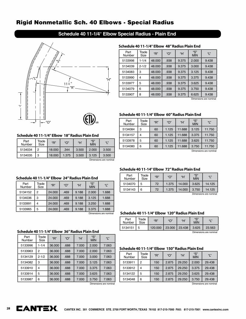
Schedule 40 11-1/4° Elbow Special Radius - Plain End
11 14 °"L"
"S"
"S"
"R"
"H"
"O"
Part Number
Trade Size “R” “O” “H’ “S”
MIN “L”
5134034 2 18.000 .344 3.500 2.000 3.500
5134035 3 18.000 1.375 3.500 3.125 3.500
Schedule 40 11-1/4° Elbow 18” Radius Plain End
Part Number
Trade Size “R” “O” “H’ “S”
MIN “L”
5133996 1-1/4 36.000 .688 7.000 2.000 7.063
5133963 2 36.000 .688 7.000 2.000 7.063
5134129 2-1/2 36.000 .688 7.000 3.000 7.063
5134082 3 36.000 .688 7.000 3.125 7.063
5133910 4 36.000 .688 7.000 3.375 7.063
5133914 5 36.000 .688 7.000 3.625 7.063
5133987 6 36.000 .688 7.000 3.750 7.063
Schedule 40 11-1/4° Elbow 36” Radius Plain End
Part Number
Trade Size “R” “O” “H’ “S”
MIN “L”
5133998 1-1/4 48.000 .938 9.375 2.000 9.438
5134039 2-1/2 48.000 .938 9.375 3.000 9.438
5134083 3 48.000 .938 9.375 3.125 9.438
5133990 4 48.000 .938 9.375 3.375 9.438
5133977 5 48.000 .938 9.375 3.625 9.438
5134079 6 48.000 .938 9.375 3.750 9.438
5133907 8 48.000 .938 9.375 6.625 9.438
Schedule 40 11-1/4° Elbow 48” Radius Plain End
Part Number
Trade Size “R” “O” “H’ “S”
MIN “L”
5134152 2 24.000 .469 9.188 2.000 1.688
5134036 3 24.000 .469 9.188 3.125 1.688
5133991 4 24.000 .469 9.188 3.250 1.688
5133965 5 24.000 .469 9.188 3.375 1.688
Schedule 40 11-1/4° Elbow 24” Radius Plain End
Part Number
Trade Size “R” “O” “H’ “S”
MIN “L”
5134084 3 60 1.125 11.688 3.125 11.750
5134157 4 60 1.125 11.688 3.375 11.750
5133978 5 60 1.125 11.688 3.625 11.750
5134080 6 60 1.125 11.688 3.750 11.750
Schedule 40 11-1/4° Elbow 60” Radius Plain End
Part Number
Trade Size “R” “O” “H’ “S”
MIN “L”
5134070 5 72 1.375 14.000 3.625 14.125
5134143 6 72 1.375 14.000 3.750 14.125
Schedule 40 11-14° Elbow 72” Radius Plain End
Part Number
Trade Size “R” “O” “H’ “S”
MIN “L”
5133911 2 150 2.875 29.250 2.000 29.438
5133912 4 150 2.875 29.250 3.375 29.438
5134122 5 150 2.875 29.250 3.625 29.438
5134048 6 150 2.875 29.250 3.750 29.438
Schedule 40 11-1/4° Elbow 150” Radius Plain End
Part Number
Trade Size “R” “O” “H’ “S”
MIN “L”
5134151 5 120.000 23.000 23.438 3.625 23.563
Schedule 40 11-1/4° Elbow 120” Radius Plain End
Dimensions are nominal
Dimensions are nominal
Dimensions are nominal Dimensions are nominal
Dimensions are nominal
Dimensions are nominal
Dimensions are nominal
Dimensions are nominal
CANTEX INC. 301 COMMERCE STE. 2700 FORT WORTH, TEXAS 76102 817-215-7000 FAX: 817-215-7001 www.cantexinc.com®
Rigid Nonmetallic Sch. 40 Elbows - Special Radius
28

90°
"O"
"B"
"R"
"S"
"H"
Schedule 40 90° Elbow Special Radius - Bell End
Part Number
Trade Size “R” “O” “H’ “S”
MIN“B”MIN “L”
5233844 1 18.000 18.000 18.000 1.875 1.500 28.250
5233923 1-1/4 18.000 18.000 18.000 2.000 1.500 28.250
5233839 1-1/2 18.000 18.000 18.000 2.000 2.000 28.250
5233846 2 18.000 18.000 18.000 2.000 2.000 28.250
5233856 2-1/2 18.000 18.000 18.000 3.000 2.250 28.250
5233850 3 18.000 18.000 18.000 3.125 2.500 28.250
5233985 4 18.000 18.000 18.000 3.375 3.250 28.250
Schedule 40 90° Elbow 18” Radius Bell End
Part Number
Trade Size “R” “O” “H’ “S”
MIN“B”MIN “L”
5234099 3/4 24.000 24.000 24.000 1.500 1.500 37.688
5233859 1 24.000 24.000 24.000 1.875 1.500 37.688
5233883 1-1/4 24.000 24.000 24.000 2.000 1.500 37.688
5233873 1-1/2 24.000 24.000 24.000 2.000 2.000 37.688
5133924 2 24.000 24.000 24.000 2.000 2.000 37.688
5233847 2-1/2 24.000 24.000 24.000 3.000 2.250 37.688
5233837 3 24.000 24.000 24.000 3.125 2.500 37.688
5233893 3-1/2 24.000 24.000 24.000 3.250 3.250 37.688
5233822 4 24.000 24.000 24.000 3.375 3.250 37.688
Schedule 40 90° Elbow 24” Radius Bell End
Part Number
Trade Size “R” “O” “H’ “S”
MIN“B”MIN “L”
5233920 2 30.000 30.000 30.000 2.000 2.000 47.125
5233981 2-1/2 30.000 30.000 30.000 3.000 2.250 47.125
5234081 3 30.000 30.000 30.000 3.125 2.500 47.125
5233852 4 30.000 30.000 30.000 3.375 3.250 47.125
5233872 5 30.000 30.000 30.000 3.625 4.250 47.125
Schedule 40 90° Elbow 30” Radius Bell End
Part Number
Trade Size “R” “O” “H’ “S”
MIN“B”MIN “L”
5233855 1 36.000 36.000 36.000 1.875 1.500 56.500
5233884 1-1/4 36.000 36.000 36.000 2.000 1.500 56.500
5233866 1-1/2 36.000 36.000 36.000 2.000 2.000 56.500
5233848 2 36.000 36.000 36.000 2.000 2.000 56.500
5233857 2-1/2 36.000 36.000 36.000 3.000 2.250 56.500
5233930 3 36.000 36.000 36.000 3.125 2.500 56.500
5233818 3-1/2 36.000 36.000 36.000 3.250 3.250 56.500
5233842 4 36.000 36.000 36.000 3.375 3.250 56.500
5233841 5 36.000 36.000 36.000 3.625 4.250 56.500
5233877 6 36.000 36.000 36.000 3.750 5.000 56.500
Schedule 40 90° Elbow 36” Radius Bell End
Part Number
Trade Size “R” “O” “H’ “S”
MIN“B”MIN “L”
5236338 1 48.000 48.000 48.000 1.875 1.500 75.375
5234053 1-1/4 48.000 48.000 48.000 2.000 1.500 75.375
5233865 1-1/2 48.000 48.000 48.000 2.000 2.000 75.375
5233876 2 48.000 48.000 48.000 2.000 2.000 75.375
5233849 2-1/2 48.000 48.000 48.000 3.000 2.250 75.375
5233817 3 48.000 48.000 48.000 3.125 2.500 75.375
5233892 3-1/2 48.000 48.000 48.000 3.250 3.250 75.375
5233843 4 48.000 48.000 48.000 3.375 3.250 75.375
5233868 5 48.000 48.000 48.000 3.625 4.250 75.375
5233816 6 48.000 48.000 48.000 3.750 5.000 75.375
Schedule 40 90° Elbow 48” Radius Bell End
Part Number
Trade Size “R” “O” “H’ “S”
MIN“B”MIN “L”
5233786 2 60.000 60.000 60.000 2.000 2.000 94.250
5233819 3 60.000 60.000 60.000 3.125 2.500 94.250
5233854 4 60.000 60.000 60.000 3.375 3.250 94.250
5233885 5 60.000 60.000 60.000 3.625 4.250 94.250
5233886 6 60.000 60.000 60.000 3.750 5.000 94.250
Schedule 40 90° Elbow 60” Radius Bell End
Dimensions are nominal
Dimensions are nominal
Dimensions are nominal
Dimensions are nominal
Dimensions are nominal
Dimensions are nominal
CANTEX INC. 301 COMMERCE STE. 2700 FORT WORTH, TEXAS 76102 817-215-7000 FAX: 817-215-7001 www.cantexinc.com 29®
Rigid Nonmetallic Sch. 40 Elbows - Special Radius
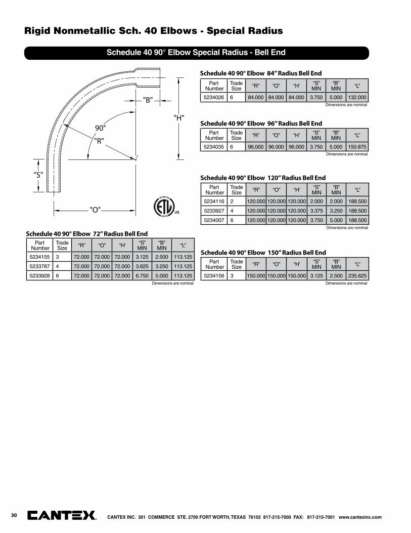
90°
"O"
"B"
"R"
"S"
"H"
Schedule 40 90° Elbow Special Radius - Bell End
Part Number
Trade Size “R” “O” “H’ “S”
MIN“B”MIN “L”
5234155 3 72.000 72.000 72.000 3.125 2.500 113.125
5233787 4 72.000 72.000 72.000 3.625 3.250 113.125
5233928 6 72.000 72.000 72.000 6.750 5.000 113.125
Schedule 40 90° Elbow 72” Radius Bell End
Part Number
Trade Size “R” “O” “H’ “S”
MIN“B”MIN “L”
5234026 6 84.000 84.000 84.000 3.750 5.000 132.000
Schedule 40 90° Elbow 84” Radius Bell End
Part Number
Trade Size “R” “O” “H’ “S”
MIN“B”MIN “L”
5234035 6 96.000 96.000 96.000 3.750 5.000 150.875
Schedule 40 90° Elbow 96” Radius Bell End
Part Number
Trade Size “R” “O” “H’ “S”
MIN“B”MIN “L”
5234116 2 120.000 120.000 120.000 2.000 2.000 188.500
5233927 4 120.000 120.000 120.000 3.375 3.250 188.500
5234007 6 120.000 120.000 120.000 3.750 5.000 188.500
Schedule 40 90° Elbow 120” Radius Bell End
Part Number
Trade Size “R” “O” “H’ “S”
MIN“B”MIN “L”
5234156 3 150.000 150.000 150.000 3.125 2.500 235.625
Schedule 40 90° Elbow 150” Radius Bell End
Dimensions are nominal Dimensions are nominal
Dimensions are nominal
Dimensions are nominal
Dimensions are nominal
CANTEX INC. 301 COMMERCE STE. 2700 FORT WORTH, TEXAS 76102 817-215-7000 FAX: 817-215-7001 www.cantexinc.com®
Rigid Nonmetallic Sch. 40 Elbows - Special Radius
30
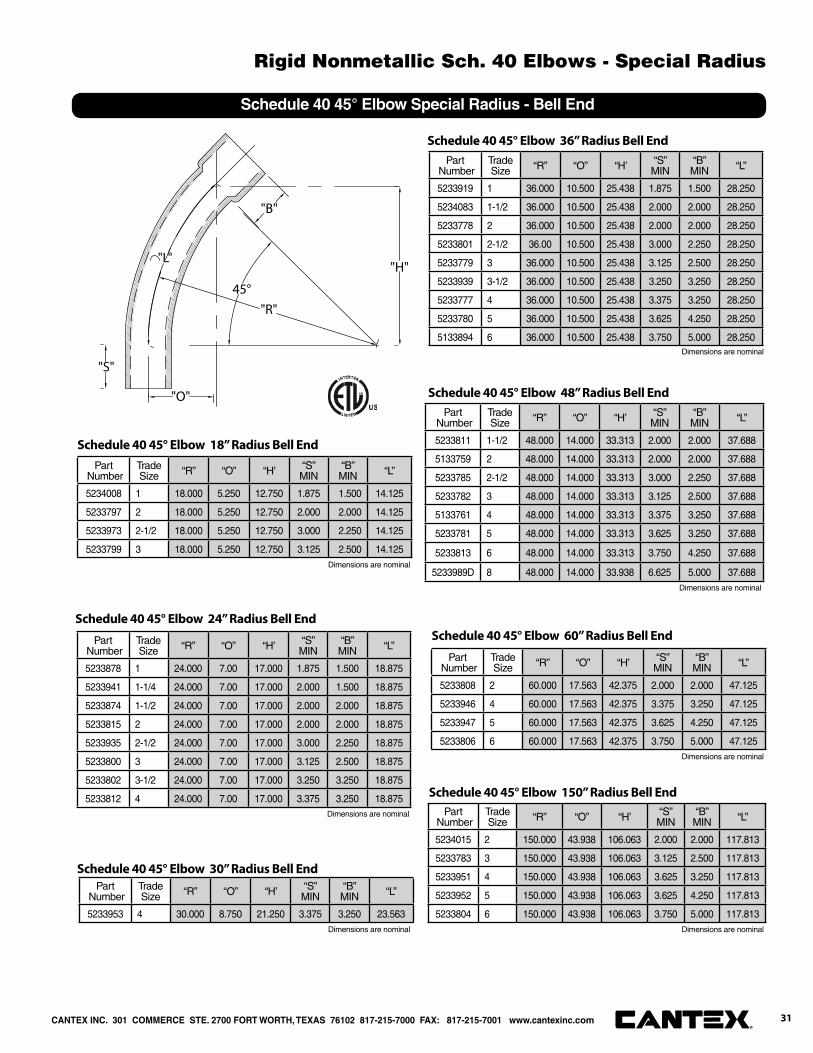
45°
"B"
"O"
"H""L"
"S"
"R"
Schedule 40 45° Elbow Special Radius - Bell End
Part Number
Trade Size “R” “O” “H’ “S”
MIN“B”MIN “L”
5234008 1 18.000 5.250 12.750 1.875 1.500 14.125
5233797 2 18.000 5.250 12.750 2.000 2.000 14.125
5233973 2-1/2 18.000 5.250 12.750 3.000 2.250 14.125
5233799 3 18.000 5.250 12.750 3.125 2.500 14.125
Schedule 40 45° Elbow 18” Radius Bell End
Part Number
Trade Size “R” “O” “H’ “S”
MIN“B”MIN “L”
5233878 1 24.000 7.00 17.000 1.875 1.500 18.875
5233941 1-1/4 24.000 7.00 17.000 2.000 1.500 18.875
5233874 1-1/2 24.000 7.00 17.000 2.000 2.000 18.875
5233815 2 24.000 7.00 17.000 2.000 2.000 18.875
5233935 2-1/2 24.000 7.00 17.000 3.000 2.250 18.875
5233800 3 24.000 7.00 17.000 3.125 2.500 18.875
5233802 3-1/2 24.000 7.00 17.000 3.250 3.250 18.875
5233812 4 24.000 7.00 17.000 3.375 3.250 18.875
Schedule 40 45° Elbow 24” Radius Bell End
Part Number
Trade Size “R” “O” “H’ “S”
MIN“B”MIN “L”
5233953 4 30.000 8.750 21.250 3.375 3.250 23.563
Schedule 40 45° Elbow 30” Radius Bell End
Part Number
Trade Size “R” “O” “H’ “S”
MIN“B”MIN “L”
5233919 1 36.000 10.500 25.438 1.875 1.500 28.250
5234083 1-1/2 36.000 10.500 25.438 2.000 2.000 28.250
5233778 2 36.000 10.500 25.438 2.000 2.000 28.250
5233801 2-1/2 36.00 10.500 25.438 3.000 2.250 28.250
5233779 3 36.000 10.500 25.438 3.125 2.500 28.250
5233939 3-1/2 36.000 10.500 25.438 3.250 3.250 28.250
5233777 4 36.000 10.500 25.438 3.375 3.250 28.250
5233780 5 36.000 10.500 25.438 3.625 4.250 28.250
5133894 6 36.000 10.500 25.438 3.750 5.000 28.250
Schedule 40 45° Elbow 36” Radius Bell End
Part Number
Trade Size “R” “O” “H’ “S”
MIN“B”MIN “L”
5233811 1-1/2 48.000 14.000 33.313 2.000 2.000 37.688
5133759 2 48.000 14.000 33.313 2.000 2.000 37.688
5233785 2-1/2 48.000 14.000 33.313 3.000 2.250 37.688
5233782 3 48.000 14.000 33.313 3.125 2.500 37.688
5133761 4 48.000 14.000 33.313 3.375 3.250 37.688
5233781 5 48.000 14.000 33.313 3.625 3.250 37.688
5233813 6 48.000 14.000 33.313 3.750 4.250 37.688
5233989D 8 48.000 14.000 33.938 6.625 5.000 37.688
Schedule 40 45° Elbow 48” Radius Bell End
Part Number
Trade Size “R” “O” “H’ “S”
MIN“B”MIN “L”
5233808 2 60.000 17.563 42.375 2.000 2.000 47.125
5233946 4 60.000 17.563 42.375 3.375 3.250 47.125
5233947 5 60.000 17.563 42.375 3.625 4.250 47.125
5233806 6 60.000 17.563 42.375 3.750 5.000 47.125
Schedule 40 45° Elbow 60” Radius Bell End
Part Number
Trade Size “R” “O” “H’ “S”
MIN“B”MIN “L”
5234015 2 150.000 43.938 106.063 2.000 2.000 117.813
5233783 3 150.000 43.938 106.063 3.125 2.500 117.813
5233951 4 150.000 43.938 106.063 3.625 3.250 117.813
5233952 5 150.000 43.938 106.063 3.625 4.250 117.813
5233804 6 150.000 43.938 106.063 3.750 5.000 117.813
Schedule 40 45° Elbow 150” Radius Bell End
Dimensions are nominal
Dimensions are nominal
Dimensions are nominal
Dimensions are nominal Dimensions are nominal
Dimensions are nominal
Dimensions are nominal
CANTEX INC. 301 COMMERCE STE. 2700 FORT WORTH, TEXAS 76102 817-215-7000 FAX: 817-215-7001 www.cantexinc.com 31®
Rigid Nonmetallic Sch. 40 Elbows - Special Radius

30°
B
L
S
R
O
H
Schedule 40 30° Elbow Special Radius - Bell End
Part Number
Trade Size “R” “O” “H’ “S”
MIN“B”MIN “L”
5233789 2 18.000 2.438 9.063 2.000 2.000 9.438
5233969 3 18.000 2.438 9.063 3.125 2.500 9.438
Schedule 40 30° Elbow 18” Radius Bell End
Part Number
Trade Size “R” “O” “H’ “S”
MIN“B”MIN “L”
5236435 1 24.000 3.188 12.000 1.875 1.500 12.563
5233803 1-1/2 24.000 3.188 12.000 2.000 2.000 12.563
5233796 2 24.000 3.188 12.000 2.000 2.000 12.563
5233958 3 24.000 3.188 12.000 3.125 2.500 12.563
5236439 3-1/2 24.000 3.188 12.000 3.250 3.250 12.563
5233788 4 24.000 3.188 12.000 3.375 3.250 12.563
Schedule 40 30° Elbow 24” Radius Bell End
Part Number
Trade Size “R” “O” “H’ “S”
MIN“B”MIN “L”
5233898 4 30.000 4.000 15.000 3.375 3.250 15.938
Schedule 40 30° Elbow 30” Radius Bell End
Part Number
Trade Size “R” “O” “H’ “S”
MIN“B”MIN “L”
5233792 2 36.000 4.813 18.000 2.000 2.000 18.875
5233793 3 36.000 4.813 18.000 3.125 2.500 18.875
5233790 4 36.000 4.813 18.000 3.375 3.250 18.875
5233933 5 36.000 4.813 18.000 3.625 4.250 18.875
5233791 6 36.000 4.813 18.000 3.750 5.000 18.875
Schedule 40 30° Elbow 36” Radius Bell End
Part Number
Trade Size “R” “O” “H’ “S”
MIN“B”MIN “L”
5233820 2 48.000 6.438 24.00 2.000 2.000 25.125
5233809 3 48.000 6.438 24.000 3.125 2.500 25.125
5233838 4 48.000 6.438 24.000 3.375 3.250 25.125
5233959 5 48.000 6.438 24.000 3.625 4.250 25.125
5233861 6 48.000 6.438 24.000 3.750 5.000 25.125
Schedule 40 30° Elbow 48” Radius Bell End
Part Number
Trade Size “R” “O” “H’ “S”
MIN“B”MIN “L”
5233999 4 60.000 8.063 30.000 3.375 3.250 31.438
Schedule 40 30° Elbow 60” Radius Bell End
Part Number
Trade Size “R” “O” “H’ “S”
MIN“B”MIN “L”
5233962 4 120.000 16.063 60.000 3.375 3.250 62.813
Schedule 40 30° Elbow 120” Radius Bell End
Part Number
Trade Size “R” “O” “H’ “S”
MIN“B”MIN “L”
5234135 3 150.000 20.125 75.000 3.125 2.500 78.563
5233964 4 150.000 20.125 75.000 3.375 3.250 78.563
Schedule 40 30° Elbow 150” Radius Bell End
Dimensions are nominal
Dimensions are nominal
Dimensions are nominal
Dimensions are nominal
Dimensions are nominal
Dimensions are nominal
Dimensions are nominal Dimensions are nominal
CANTEX INC. 301 COMMERCE STE. 2700 FORT WORTH, TEXAS 76102 817-215-7000 FAX: 817-215-7001 www.cantexinc.com®
Rigid Nonmetallic Sch. 40 Elbows - Special Radius
32
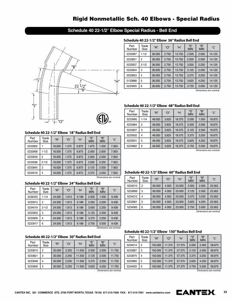
22 1/2°
"B"
"L"
"S"
"H"
"O"
"R"
Schedule 40 22-1/2° Elbow Special Radius - Bell End
Part Number
Trade Size “R” “O” “H’ “S”
MIN“B”MIN “L”
5233902 1 18.000 1.375 6.875 1.875 1.500 7.063
5233908 1-1/2 18.000 1.375 6.875 2.000 2.000 7.063
5233639 2 18.000 1.375 6.875 2.000 2.000 7.063
5233936 2-1/2 18.000 1.375 6.875 3.000 2.250 7.063
5233845 3 18.000 1.375 6.875 3.125 2.500 7.063
5234016 4 18.000 1.375 6.875 3.375 3.250 7.063
Schedule 40 22-1/2° Elbow 18” Radius Bell End
Part Number
Trade Size “R” “O” “H’ “S”
MIN“B”MIN “L”
5236425 1-1/4 24.000 1.813 9.188 2.000 1.500 9.438
5233915 2 24.000 1.813 9.188 2.000 2.000 9.438
5234019 2-1/2 24.000 1.813 9.188 3.000 2.250 9.438
5233903 3 24.000 1.813 9.188 3.125 2.500 9.438
5233909 4 24.000 1.813 9.188 3.375 3.250 9.438
5233917 6 24.000 1.813 9.188 3.750 5.000 9.438
Schedule 40 22-1/2° Elbow 24” Radius Bell End
Part Number
Trade Size “R” “O” “H’ “S”
MIN“B”MIN “L”
5233810 2 30.000 2.250 11.500 2.000 2.000 11.750
5233821 3 30.000 2.250 11.500 3.125 2.500 11.750
5233948 4 30.000 2.250 11.500 3.375 3.250 11.750
5233900 5 30.000 2.250 11.500 3.625 4.250 11.750
Schedule 40 22-1/2° Elbow 30” Radius Bell End
Part Number
Trade Size “R” “O” “H’ “S”
MIN“B”MIN “L”
5233997 1-1/2 36.000 2.750 13.750 2.000 2.000 14.125
5233851 2 36.000 2.750 13.750 2.000 2.000 14.125
5233937 2-1/2 36.000 2.750 13.750 3.000 2.250 14.125
5233904 3 36.000 2.750 13.750 3.125 2.500 14.125
5233853 4 36.000 2.750 13.750 3.375 3.250 14.125
5133888 5 36.000 2.750 13.750 3.625 4.250 14.125
5233905 6 36.000 2.750 13.750 3.750 5.000 14.125
Schedule 40 22-1/2° Elbow 36” Radius Bell End
Part Number
Trade Size “R” “O” “H’ “S”
MIN“B”MIN “L”
5233995 1-1/4 48.000 3.625 18.375 2.000 1.500 18.875
5233984 2 48.000 3.625 18.375 2.000 2.000 18.875
5233907 3 48.000 3.625 18.375 3.125 2.500 18.875
5233932 4 48.000 3.625 18.375 3.375 3.250 18.875
5233931 5 48.000 3.625 18.375 3.625 4.250 18.875
5233862 6 48.000 3.625 18.375 3.750 5.000 18.875
Schedule 40 22-1/2° Elbow 48” Radius Bell End
Part Number
Trade Size “R” “O” “H’ “S”
MIN“B”MIN “L”
5234013 2 60.000 4.563 23.000 2.000 2.000 23.563
5233899 3 60.000 4.563 23.000 3.125 2.500 23.563
5234012 4 60.000 4.563 23.000 3.375 3.250 23.563
5233961 5 60.000 4.563 23.000 3.625 4.250 23.563
5234065 6 60.000 4.563 23.000 3.750 5.000 23.563
Schedule 40 22-1/2° Elbow 60” Radius Bell End
Part Number
Trade Size “R” “O” “H’ “S”
MIN“B”MIN “L”
5234014 2 150.000 11.375 57.375 2.000 2.000 58.875
5233887 3 150.000 11.375 57.375 3.125 2.500 58.875
5233870 4 150.000 11.375 57.375 3.375 3.250 58.875
5233960 5 150.000 11.375 57.375 3.625 4.250 58.875
5234055 6 150.000 11.375 57.375 3.750 5.000 58.875
Schedule 40 22-1/2° Elbow 150” Radius Bell End
Dimensions are nominal Dimensions are nominal
Dimensions are nominal
Dimensions are nominal
Dimensions are nominal
Dimensions are nominal
Dimensions are nominal
CANTEX INC. 301 COMMERCE STE. 2700 FORT WORTH, TEXAS 76102 817-215-7000 FAX: 817-215-7001 www.cantexinc.com 33®
Rigid Nonmetallic Sch. 40 Elbows - Special Radius
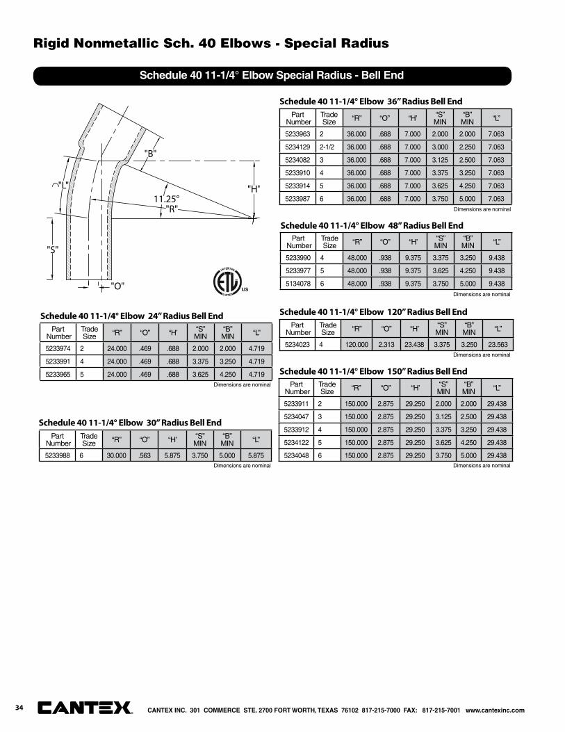
11.25°
"B"
"L"
"S"
"H"
"O"
"R"
Schedule 40 11-1/4° Elbow Special Radius - Bell End
Part Number
Trade Size “R” “O” “H’ “S”
MIN“B”MIN “L”
5233974 2 24.000 .469 .688 2.000 2.000 4.719
5233991 4 24.000 .469 .688 3.375 3.250 4.719
5233965 5 24.000 .469 .688 3.625 4.250 4.719
Schedule 40 11-1/4° Elbow 24” Radius Bell End
Part Number
Trade Size “R” “O” “H’ “S”
MIN“B”MIN “L”
5233988 6 30.000 .563 5.875 3.750 5.000 5.875
Schedule 40 11-1/4° Elbow 30” Radius Bell End
Part Number
Trade Size “R” “O” “H’ “S”
MIN“B”MIN “L”
5233963 2 36.000 .688 7.000 2.000 2.000 7.063
5234129 2-1/2 36.000 .688 7.000 3.000 2.250 7.063
5234082 3 36.000 .688 7.000 3.125 2.500 7.063
5233910 4 36.000 .688 7.000 3.375 3.250 7.063
5233914 5 36.000 .688 7.000 3.625 4.250 7.063
5233987 6 36.000 .688 7.000 3.750 5.000 7.063
Schedule 40 11-1/4° Elbow 36” Radius Bell End
Part Number
Trade Size “R” “O” “H’ “S”
MIN“B”MIN “L”
5233990 4 48.000 .938 9.375 3.375 3.250 9.438
5233977 5 48.000 .938 9.375 3.625 4.250 9.438
5134078 6 48.000 .938 9.375 3.750 5.000 9.438
Schedule 40 11-1/4° Elbow 48” Radius Bell End
Part Number
Trade Size “R” “O” “H’ “S”
MIN“B”MIN “L”
5234023 4 120.000 2.313 23.438 3.375 3.250 23.563
Schedule 40 11-1/4° Elbow 120” Radius Bell End
Part Number
Trade Size “R” “O” “H’ “S”
MIN“B”MIN “L”
5233911 2 150.000 2.875 29.250 2.000 2.000 29.438
5234047 3 150.000 2.875 29.250 3.125 2.500 29.438
5233912 4 150.000 2.875 29.250 3.375 3.250 29.438
5234122 5 150.000 2.875 29.250 3.625 4.250 29.438
5234048 6 150.000 2.875 29.250 3.750 5.000 29.438
Schedule 40 11-1/4° Elbow 150” Radius Bell End
Dimensions are nominal
Dimensions are nominal
Dimensions are nominal
Dimensions are nominal
Dimensions are nominal
Dimensions are nominal
CANTEX INC. 301 COMMERCE STE. 2700 FORT WORTH, TEXAS 76102 817-215-7000 FAX: 817-215-7001 www.cantexinc.com®
Rigid Nonmetallic Sch. 40 Elbows - Special Radius
34

Part Number
Trade Size
Carton Qty. “R” “O” “H’ “S”
MIN “L”
5121053 1/2 50 4.000 4.000 4.000 1.500 6.250
5121054 3/4 35 4.500 4.500 4.500 1.500 7.125
5121055 1 20 5.750 5.750 5.750 1.875 9.000
5121056 1-1/4 30 7.250 7.250 7.250 2.000 11.375
5121057 1-1/2 30 8.250 8.250 8.250 2.000 13.000
5121058 2 15 9.500 9.500 9.500 2.000 15.000
5121059 2-1/2 18 10.500 10.500 10.500 3.000 16.500
5121060 3 14 13.000 13.000 13.000 3.125 20.375
5121068 3-1/2 12 15.000 15.000 15.000 3.250 23.500
5121061 4 10 16.000 16.000 16.000 3.375 25.125
5121062 5 30* 24.000 24.000 24.000 3.625 37.625
5121063 6 25* 30.000 30.000 30.000 3.750 47.125
90°
"O"
"S"
R
"H"
"S"
"L"
Conforms to UL651 and NEMA TC3
Material is Rigid PVC
Bend Tolerance is ±2°
Schedule 80 90° Elbow - Plain End
Part Number
Trade Size
Carton Qty. “R” “O” “H’ “S”
MIN “L”
5121003 1/2 50 4.000 1.188 2.875 1.500 3.125
5121004 3/4 25 4.500 1.313 3.188 1.500 3.500
5121005 1 20 5.750 1.688 4.000 1.875 4.500
5121006 1-1/4 25 7.250 2.125 5.125 2.000 5.688
5121007 1-1/2 20 8.250 2.375 5.875 2.000 6.500
5121008 2 10 9.500 2.813 6.750 2.000 7.500
5121009 2-1/2 20 10.500 2.563 7.375 3.000 8.250
5121010 3 8 13.000 3.813 9.188 3.125 10.250
5121011 4 20 16.000 4.688 11.438 3.375 12.625
5121012 5 30* 24.00 7.000 17.000 3.625 18.875
5121013 6 25* 30.000 8.813 21.250 3.750 23.875
"S"
45°
"S"
"L"
"O"
"H"
"R"
Conforms to UL651 and NEMA TC3
Material is Rigid PVC
Bend Tolerance is ±2°
Schedule 80 45° Elbow - Plain End
Dimensions are nominal
Dimensions are nominal
* Pallet Quantity
* Pallet Quantity
CANTEX INC. 301 COMMERCE STE. 2700 FORT WORTH, TEXAS 76102 817-215-7000 FAX: 817-215-7001 www.cantexinc.com 35®
Rigid Nonmetallic Sch. 80 Elbows - Standard Radius

30°
S
R
L H
S
O
Conforms to UL651 and NEMA TC3
Material is Rigid PVC
Bend Tolerance is ±2°
Schedule 80 30° Elbow - Plain End
Part Number
Trade Size
Carton Qty. “R” “O” “H’ “S”
MIN “L”
5136649 1-1/2 25 8.250 .625 3.125 2.000 3.250
5136659 2 10 9.500 .750 3.625 2.000 3.750
5136669 2-1/2 20 10.500 .813 4.000 3.000 4.125
5136679 3 8 13.000 1.000 5.000 3.125 5.125
5121868 4 20 16.000 1.250 6.125 3.375 6.250
5121125 5 *60 24.000 1.813 9.188 3.625 9.375
22 1/2°"L"
"S"
"S"
"R"
"H"
"O"
Conforms to UL651 and NEMA TC3
Material is Rigid PVC
Bend Tolerance is ±2°°
Schedule 80 22-1/2° Elbow - Plain End
* Pallet Quantity
* Pallet Quantity
Dimensions are nominal
Dimensions are nominal
Part Number
Trade Size
Carton Qty. “R” “O” “H’ “S”
MIN “L”
5121000 1/2 50 4.000 .500 2.000 1.500 2.125
5121001 3/4 25 4.500 .625 2.250 1.500 2.375
5121002 1 20 5.750 .750 2.875 1.875 3.000
5121106 1-1/4 25 7.250 1.000 3.625 2.000 3.813
5121850 1-1/2 20 8.250 1.063 4.125 2.000 4.313
5121108 2 10 9.500 1.250 4.750 2.000 5.000
5121109 2-1/2 20 10.500 1.438 5.250 3.000 5.500
5121110 3 8 13.000 1.750 6.500 3.125 6.813
5121111 4 20 16.000 2.063 8.000 3.375 8.375
5121112 5 30* 24.000 3.188 12.000 3.625 12.563
5121113 6 25* 30.000 4.000 15.000 3.750 15.688
CANTEX INC. 301 COMMERCE STE. 2700 FORT WORTH, TEXAS 76102 817-215-7000 FAX: 817-215-7001 www.cantexinc.com®
Rigid Nonmetallic Sch. 80 Elbows - Standard Radius
36
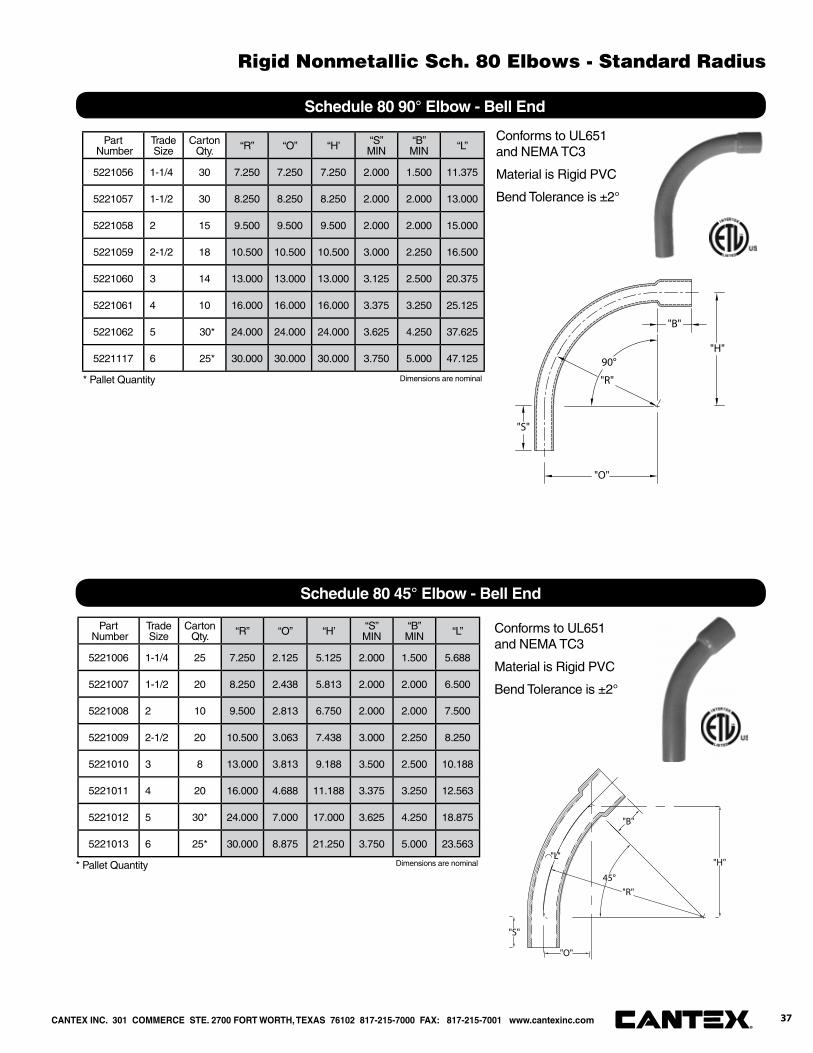
Part Number
Trade Size
Carton Qty. “R” “O” “H’ “S”
MIN“B”MIN “L”
5221056 1-1/4 30 7.250 7.250 7.250 2.000 1.500 11.375
5221057 1-1/2 30 8.250 8.250 8.250 2.000 2.000 13.000
5221058 2 15 9.500 9.500 9.500 2.000 2.000 15.000
5221059 2-1/2 18 10.500 10.500 10.500 3.000 2.250 16.500
5221060 3 14 13.000 13.000 13.000 3.125 2.500 20.375
5221061 4 10 16.000 16.000 16.000 3.375 3.250 25.125
5221062 5 30* 24.000 24.000 24.000 3.625 4.250 37.625
5221117 6 25* 30.000 30.000 30.000 3.750 5.000 47.125 90°
"O"
"B"
"R"
"S"
"H"
Conforms to UL651 and NEMA TC3
Material is Rigid PVC
Bend Tolerance is ±2°
Schedule 80 90° Elbow - Bell End
45°
"B"
"O"
"H""L"
"S"
"R"
Conforms to UL651 and NEMA TC3
Material is Rigid PVC
Bend Tolerance is ±2°
Schedule 80 45° Elbow - Bell End
Part Number
Trade Size
Carton Qty. “R” “O” “H’ “S”
MIN“B”MIN “L”
5221006 1-1/4 25 7.250 2.125 5.125 2.000 1.500 5.688
5221007 1-1/2 20 8.250 2.438 5.813 2.000 2.000 6.500
5221008 2 10 9.500 2.813 6.750 2.000 2.000 7.500
5221009 2-1/2 20 10.500 3.063 7.438 3.000 2.250 8.250
5221010 3 8 13.000 3.813 9.188 3.500 2.500 10.188
5221011 4 20 16.000 4.688 11.188 3.375 3.250 12.563
5221012 5 30* 24.000 7.000 17.000 3.625 4.250 18.875
5221013 6 25* 30.000 8.875 21.250 3.750 5.000 23.563
* Pallet Quantity
* Pallet Quantity
Dimensions are nominal
Dimensions are nominal
CANTEX INC. 301 COMMERCE STE. 2700 FORT WORTH, TEXAS 76102 817-215-7000 FAX: 817-215-7001 www.cantexinc.com 37®
Rigid Nonmetallic Sch. 80 Elbows - Standard Radius
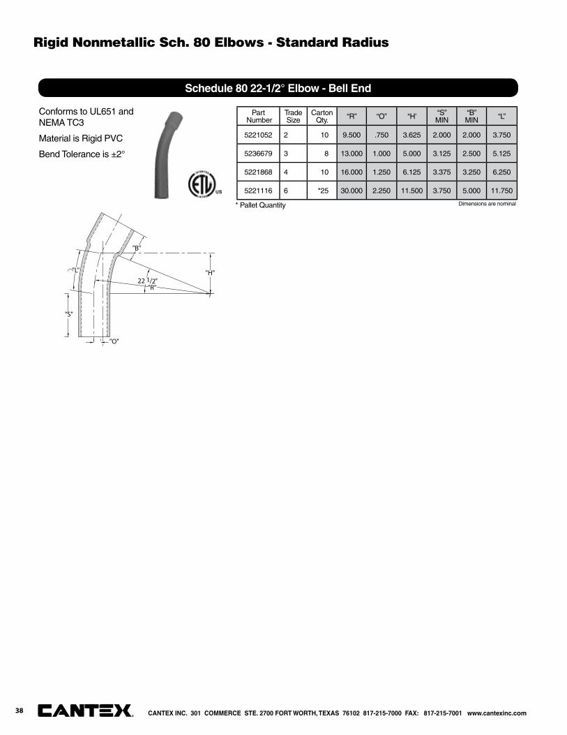
22 1/2°
"B"
"L"
"S"
"H"
"O"
"R"
Conforms to UL651 and NEMA TC3
Material is Rigid PVC
Bend Tolerance is ±2°
Schedule 80 22-1/2° Elbow - Bell End
Part Number
Trade Size
Carton Qty. “R” “O” “H’ “S”
MIN“B”MIN “L”
5221052 2 10 9.500 .750 3.625 2.000 2.000 3.750
5236679 3 8 13.000 1.000 5.000 3.125 2.500 5.125
5221868 4 10 16.000 1.250 6.125 3.375 3.250 6.250
5221116 6 *25 30.000 2.250 11.500 3.750 5.000 11.750
Dimensions are nominal * Pallet Quantity
CANTEX INC. 301 COMMERCE STE. 2700 FORT WORTH, TEXAS 76102 817-215-7000 FAX: 817-215-7001 www.cantexinc.com®
Rigid Nonmetallic Sch. 80 Elbows - Standard Radius
38
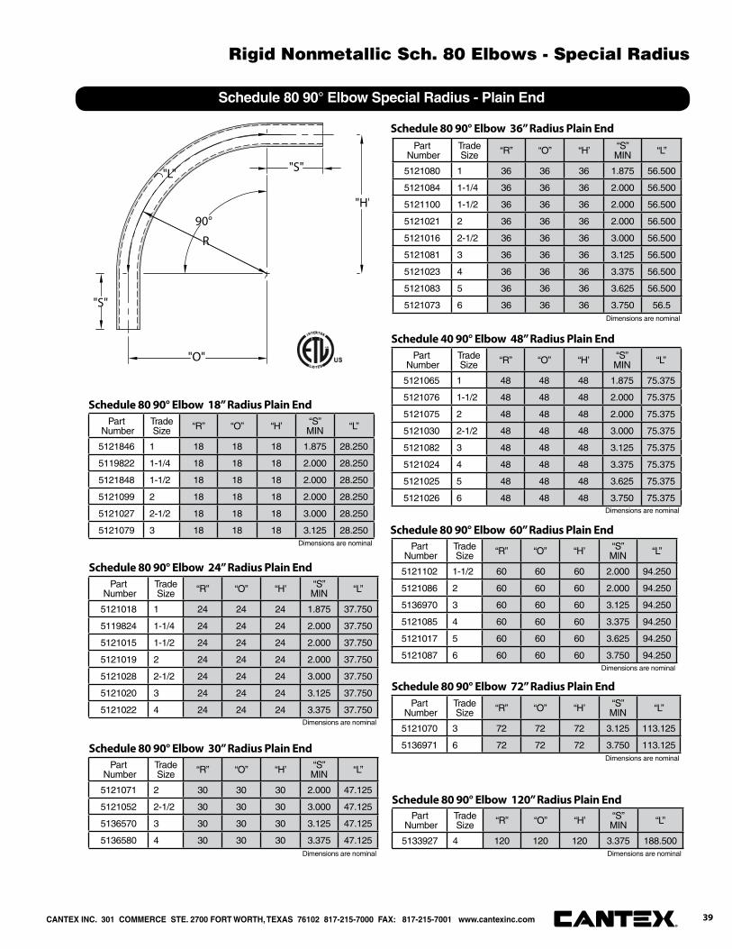
Part Number
Trade Size “R” “O” “H’ “S”
MIN “L”
5121846 1 18 18 18 1.875 28.250
5119822 1-1/4 18 18 18 2.000 28.250
5121848 1-1/2 18 18 18 2.000 28.250
5121099 2 18 18 18 2.000 28.250
5121027 2-1/2 18 18 18 3.000 28.250
5121079 3 18 18 18 3.125 28.250
Schedule 80 90° Elbow 18” Radius Plain End
Part Number
Trade Size “R” “O” “H’ “S”
MIN “L”
5121018 1 24 24 24 1.875 37.750
5119824 1-1/4 24 24 24 2.000 37.750
5121015 1-1/2 24 24 24 2.000 37.750
5121019 2 24 24 24 2.000 37.750
5121028 2-1/2 24 24 24 3.000 37.750
5121020 3 24 24 24 3.125 37.750
5121022 4 24 24 24 3.375 37.750
Schedule 80 90° Elbow 24” Radius Plain End
Part Number
Trade Size “R” “O” “H’ “S”
MIN “L”
5121071 2 30 30 30 2.000 47.125
5121052 2-1/2 30 30 30 3.000 47.125
5136570 3 30 30 30 3.125 47.125
5136580 4 30 30 30 3.375 47.125
Schedule 80 90° Elbow 30” Radius Plain End
Part Number
Trade Size “R” “O” “H’ “S”
MIN “L”
5121080 1 36 36 36 1.875 56.500
5121084 1-1/4 36 36 36 2.000 56.500
5121100 1-1/2 36 36 36 2.000 56.500
5121021 2 36 36 36 2.000 56.500
5121016 2-1/2 36 36 36 3.000 56.500
5121081 3 36 36 36 3.125 56.500
5121023 4 36 36 36 3.375 56.500
5121083 5 36 36 36 3.625 56.500
5121073 6 36 36 36 3.750 56.5
Schedule 80 90° Elbow 36” Radius Plain End
Part Number
Trade Size “R” “O” “H’ “S”
MIN “L”
5121065 1 48 48 48 1.875 75.375
5121076 1-1/2 48 48 48 2.000 75.375
5121075 2 48 48 48 2.000 75.375
5121030 2-1/2 48 48 48 3.000 75.375
5121082 3 48 48 48 3.125 75.375
5121024 4 48 48 48 3.375 75.375
5121025 5 48 48 48 3.625 75.375
5121026 6 48 48 48 3.750 75.375
Schedule 40 90° Elbow 48” Radius Plain End
Part Number
Trade Size “R” “O” “H’ “S”
MIN “L”
5121102 1-1/2 60 60 60 2.000 94.250
5121086 2 60 60 60 2.000 94.250
5136970 3 60 60 60 3.125 94.250
5121085 4 60 60 60 3.375 94.250
5121017 5 60 60 60 3.625 94.250
5121087 6 60 60 60 3.750 94.250
Schedule 80 90° Elbow 60” Radius Plain End
Part Number
Trade Size “R” “O” “H’ “S”
MIN “L”
5121070 3 72 72 72 3.125 113.125
5136971 6 72 72 72 3.750 113.125
Schedule 80 90° Elbow 72” Radius Plain End
Dimensions are nominal
Part Number
Trade Size “R” “O” “H’ “S”
MIN “L”
5133927 4 120 120 120 3.375 188.500
Schedule 80 90° Elbow 120” Radius Plain End
90°
"O"
"S"
R
"H"
"S"
"L"
Schedule 80 90° Elbow Special Radius - Plain End
Dimensions are nominal
Dimensions are nominal
Dimensions are nominal Dimensions are nominal
Dimensions are nominal
Dimensions are nominal
Dimensions are nominal
CANTEX INC. 301 COMMERCE STE. 2700 FORT WORTH, TEXAS 76102 817-215-7000 FAX: 817-215-7001 www.cantexinc.com 39®
Rigid Nonmetallic Sch. 80 Elbows - Special Radius
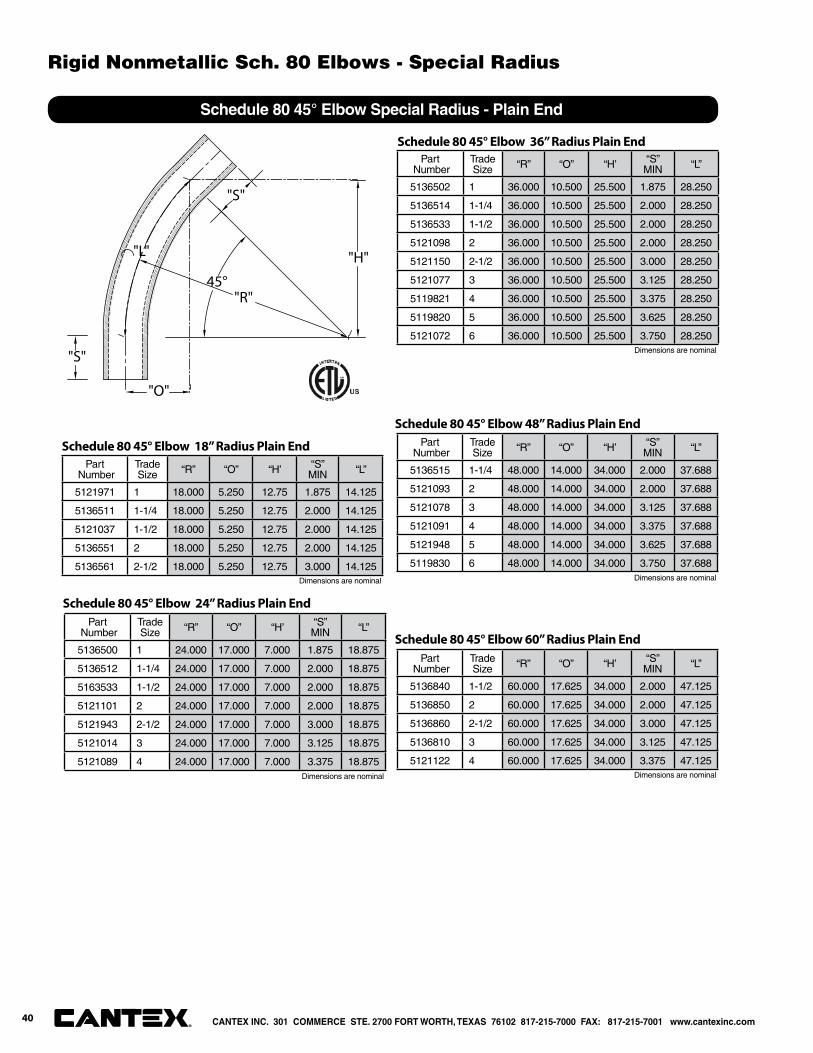
Schedule 80 45° Elbow Special Radius - Plain End
"S"
45°
"S"
"L"
"O"
"H"
"R"
Part Number
Trade Size “R” “O” “H’ “S”
MIN “L”
5121971 1 18.000 5.250 12.75 1.875 14.125
5136511 1-1/4 18.000 5.250 12.75 2.000 14.125
5121037 1-1/2 18.000 5.250 12.75 2.000 14.125
5136551 2 18.000 5.250 12.75 2.000 14.125
5136561 2-1/2 18.000 5.250 12.75 3.000 14.125
Schedule 80 45° Elbow 18” Radius Plain End
Part Number
Trade Size “R” “O” “H’ “S”
MIN “L”
5136500 1 24.000 17.000 7.000 1.875 18.875
5136512 1-1/4 24.000 17.000 7.000 2.000 18.875
5163533 1-1/2 24.000 17.000 7.000 2.000 18.875
5121101 2 24.000 17.000 7.000 2.000 18.875
5121943 2-1/2 24.000 17.000 7.000 3.000 18.875
5121014 3 24.000 17.000 7.000 3.125 18.875
5121089 4 24.000 17.000 7.000 3.375 18.875
Schedule 80 45° Elbow 24” Radius Plain End
Part Number
Trade Size “R” “O” “H’ “S”
MIN “L”
5136502 1 36.000 10.500 25.500 1.875 28.250
5136514 1-1/4 36.000 10.500 25.500 2.000 28.250
5136533 1-1/2 36.000 10.500 25.500 2.000 28.250
5121098 2 36.000 10.500 25.500 2.000 28.250
5121150 2-1/2 36.000 10.500 25.500 3.000 28.250
5121077 3 36.000 10.500 25.500 3.125 28.250
5119821 4 36.000 10.500 25.500 3.375 28.250
5119820 5 36.000 10.500 25.500 3.625 28.250
5121072 6 36.000 10.500 25.500 3.750 28.250
Schedule 80 45° Elbow 36” Radius Plain End
Part Number
Trade Size “R” “O” “H’ “S”
MIN “L”
5136515 1-1/4 48.000 14.000 34.000 2.000 37.688
5121093 2 48.000 14.000 34.000 2.000 37.688
5121078 3 48.000 14.000 34.000 3.125 37.688
5121091 4 48.000 14.000 34.000 3.375 37.688
5121948 5 48.000 14.000 34.000 3.625 37.688
5119830 6 48.000 14.000 34.000 3.750 37.688
Schedule 80 45° Elbow 48” Radius Plain End
Part Number
Trade Size “R” “O” “H’ “S”
MIN “L”
5136840 1-1/2 60.000 17.625 34.000 2.000 47.125
5136850 2 60.000 17.625 34.000 2.000 47.125
5136860 2-1/2 60.000 17.625 34.000 3.000 47.125
5136810 3 60.000 17.625 34.000 3.125 47.125
5121122 4 60.000 17.625 34.000 3.375 47.125
Schedule 80 45° Elbow 60” Radius Plain End
Dimensions are nominal
Dimensions are nominal Dimensions are nominal
Dimensions are nominal
Dimensions are nominal
CANTEX INC. 301 COMMERCE STE. 2700 FORT WORTH, TEXAS 76102 817-215-7000 FAX: 817-215-7001 www.cantexinc.com®
Rigid Nonmetallic Sch. 80 Elbows - Special Radius
40
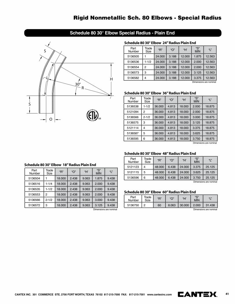
Schedule 80 30° Elbow Special Radius - Plain End
30°
S
R
L H
S
O
Part Number
Trade Size “R” “O” “H’ “S”
MIN “L”
5136538 1-1/2 36.000 4.813 18.000 2.000 18.875
5121094 2 36.000 4.813 18.000 2.000 18.875
5136566 2-1/2 36.000 4.813 18.000 3.000 18.875
5136575 3 36.000 4.813 18.000 3.125 18.875
5121114 4 36.000 4.813 18.000 3.375 18.875
5136587 5 36.000 4.813 18.000 3.625 18.875
5136595 6 36.000 4.813 18.000 3.750 18.875
Schedule 80 30° Elbow 36” Radius Plain End
Part Number
Trade Size “R” “O” “H’ “S”
MIN “L”
5121123 4 48.000 6.438 24.000 3.375 25.125
5121115 5 48.000 6.438 24.000 3.625 25.125
5136596 6 48.000 6.438 24.000 3.750 25.125
Schedule 80 30° Elbow 48” Radius Plain End
Part Number
Trade Size “R” “O” “H’ “S”
MIN “L”
5136750 2 60 8.063 30.000 2.000 31.438
Schedule 80 30° Elbow 60” Radius Plain End
Part Number
Trade Size “R” “O” “H’ “S”
MIN “L”
5136504 1 18.000 2.438 9.063 1.875 9.438
5136516 1-1/4 18.000 2.438 9.063 2.000 9.438
5136535 1-1/2 18.000 2.438 9.063 2.000 9.438
5136553 2 18.000 2.438 9.063 2.000 9.438
5136566 2-1/2 18.000 2.438 9.063 3.000 9.438
5136572 3 18.000 2.438 9.063 3.125 9.438
Schedule 80 30° Elbow 18” Radius Plain End
Part Number
Trade Size “R” “O” “H’ “S”
MIN “L”
5136505 1 24.000 3.188 12.000 1.875 12.563
5136536 1-1/2 24.000 3.188 12.000 2.000 12.563
5136554 2 24.000 3.188 12.000 2.000 12.563
5136573 3 24.000 3.188 12.000 3.125 12.563
5136582 4 24.000 3.188 12.000 3.375 12.563
Schedule 80 30° Elbow 24” Radius Plain End
Dimensions are nominal
Dimensions are nominal
Dimensions are nominal
Dimensions are nominal
Dimensions are nominal
CANTEX INC. 301 COMMERCE STE. 2700 FORT WORTH, TEXAS 76102 817-215-7000 FAX: 817-215-7001 www.cantexinc.com 41®
Rigid Nonmetallic Sch. 80 Elbows - Special Radius
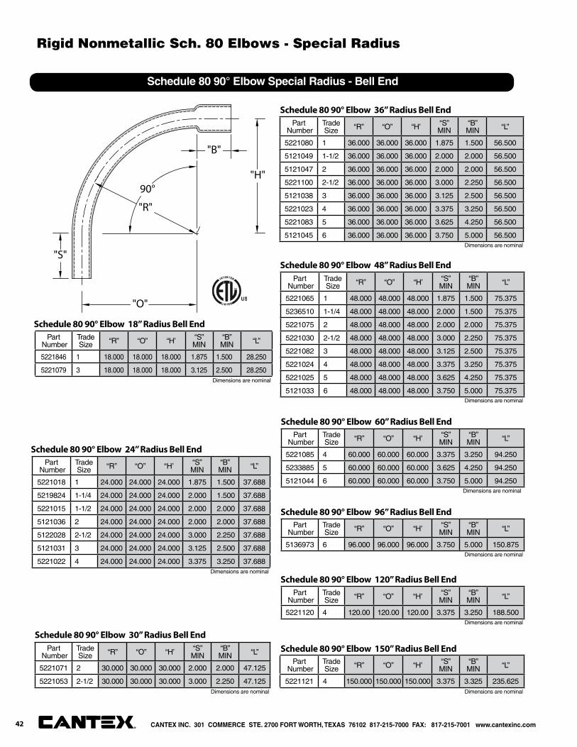
90°
"O"
"B"
"R"
"S"
"H"
Schedule 80 90° Elbow Special Radius - Bell End
Part Number
Trade Size “R” “O” “H’ “S”
MIN“B”MIN “L”
5221846 1 18.000 18.000 18.000 1.875 1.500 28.250
5221079 3 18.000 18.000 18.000 3.125 2.500 28.250
Schedule 80 90° Elbow 18” Radius Bell End
Part Number
Trade Size “R” “O” “H’ “S”
MIN“B”MIN “L”
5221018 1 24.000 24.000 24.000 1.875 1.500 37.688
5219824 1-1/4 24.000 24.000 24.000 2.000 1.500 37.688
5221015 1-1/2 24.000 24.000 24.000 2.000 2.000 37.688
5121036 2 24.000 24.000 24.000 2.000 2.000 37.688
5122028 2-1/2 24.000 24.000 24.000 3.000 2.250 37.688
5121031 3 24.000 24.000 24.000 3.125 2.500 37.688
5221022 4 24.000 24.000 24.000 3.375 3.250 37.688
Schedule 80 90° Elbow 24” Radius Bell End
Part Number
Trade Size “R” “O” “H’ “S”
MIN“B”MIN “L”
5221071 2 30.000 30.000 30.000 2.000 2.000 47.125
5221053 2-1/2 30.000 30.000 30.000 3.000 2.250 47.125
Schedule 80 90° Elbow 30” Radius Bell End
Part Number
Trade Size “R” “O” “H’ “S”
MIN“B”MIN “L”
5221080 1 36.000 36.000 36.000 1.875 1.500 56.500
5121049 1-1/2 36.000 36.000 36.000 2.000 2.000 56.500
5121047 2 36.000 36.000 36.000 2.000 2.000 56.500
5221100 2-1/2 36.000 36.000 36.000 3.000 2.250 56.500
5121038 3 36.000 36.000 36.000 3.125 2.500 56.500
5221023 4 36.000 36.000 36.000 3.375 3.250 56.500
5221083 5 36.000 36.000 36.000 3.625 4.250 56.500
5121045 6 36.000 36.000 36.000 3.750 5.000 56.500
Schedule 80 90° Elbow 36” Radius Bell End
Part Number
Trade Size “R” “O” “H’ “S”
MIN“B”MIN “L”
5221065 1 48.000 48.000 48.000 1.875 1.500 75.375
5236510 1-1/4 48.000 48.000 48.000 2.000 1.500 75.375
5221075 2 48.000 48.000 48.000 2.000 2.000 75.375
5221030 2-1/2 48.000 48.000 48.000 3.000 2.250 75.375
5221082 3 48.000 48.000 48.000 3.125 2.500 75.375
5221024 4 48.000 48.000 48.000 3.375 3.250 75.375
5221025 5 48.000 48.000 48.000 3.625 4.250 75.375
5121033 6 48.000 48.000 48.000 3.750 5.000 75.375
Schedule 80 90° Elbow 48” Radius Bell End
Part Number
Trade Size “R” “O” “H’ “S”
MIN“B”MIN “L”
5221085 4 60.000 60.000 60.000 3.375 3.250 94.250
5233885 5 60.000 60.000 60.000 3.625 4.250 94.250
5121044 6 60.000 60.000 60.000 3.750 5.000 94.250
Schedule 80 90° Elbow 60” Radius Bell End
Part Number
Trade Size “R” “O” “H’ “S”
MIN“B”MIN “L”
5136973 6 96.000 96.000 96.000 3.750 5.000 150.875
Schedule 80 90° Elbow 96” Radius Bell End
Part Number
Trade Size “R” “O” “H’ “S”
MIN“B”MIN “L”
5221120 4 120.00 120.00 120.00 3.375 3.250 188.500
Schedule 80 90° Elbow 120” Radius Bell End
Part Number
Trade Size “R” “O” “H’ “S”
MIN“B”MIN “L”
5221121 4 150.000 150.000 150.000 3.375 3.325 235.625
Schedule 80 90° Elbow 150” Radius Bell End
Dimensions are nominal
Dimensions are nominal
Dimensions are nominal
Dimensions are nominal
Dimensions are nominal
Dimensions are nominal Dimensions are nominal
Dimensions are nominal
Dimensions are nominal
CANTEX INC. 301 COMMERCE STE. 2700 FORT WORTH, TEXAS 76102 817-215-7000 FAX: 817-215-7001 www.cantexinc.com®
Rigid Nonmetallic Sch. 80 Elbows - Special Radius
42
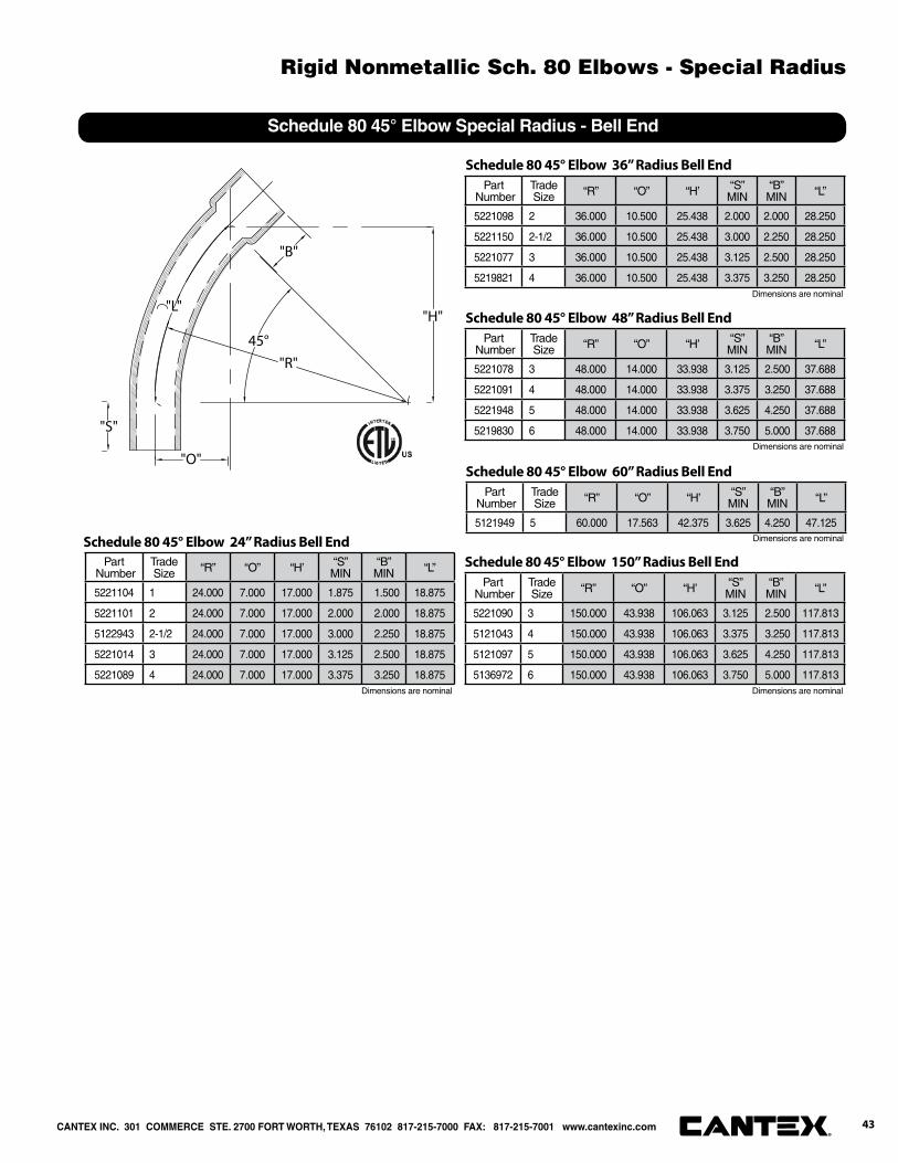
45°
"B"
"O"
"H""L"
"S"
"R"
Schedule 80 45° Elbow Special Radius - Bell End
Part Number
Trade Size “R” “O” “H’ “S”
MIN“B”MIN “L”
5221104 1 24.000 7.000 17.000 1.875 1.500 18.875
5221101 2 24.000 7.000 17.000 2.000 2.000 18.875
5122943 2-1/2 24.000 7.000 17.000 3.000 2.250 18.875
5221014 3 24.000 7.000 17.000 3.125 2.500 18.875
5221089 4 24.000 7.000 17.000 3.375 3.250 18.875
Schedule 80 45° Elbow 24” Radius Bell End
Part Number
Trade Size “R” “O” “H’ “S”
MIN“B”MIN “L”
5221098 2 36.000 10.500 25.438 2.000 2.000 28.250
5221150 2-1/2 36.000 10.500 25.438 3.000 2.250 28.250
5221077 3 36.000 10.500 25.438 3.125 2.500 28.250
5219821 4 36.000 10.500 25.438 3.375 3.250 28.250
Schedule 80 45° Elbow 36” Radius Bell End
Part Number
Trade Size “R” “O” “H’ “S”
MIN“B”MIN “L”
5221078 3 48.000 14.000 33.938 3.125 2.500 37.688
5221091 4 48.000 14.000 33.938 3.375 3.250 37.688
5221948 5 48.000 14.000 33.938 3.625 4.250 37.688
5219830 6 48.000 14.000 33.938 3.750 5.000 37.688
Schedule 80 45° Elbow 48” Radius Bell End
Part Number
Trade Size “R” “O” “H’ “S”
MIN“B”MIN “L”
5121949 5 60.000 17.563 42.375 3.625 4.250 47.125
Schedule 80 45° Elbow 60” Radius Bell End
Part Number
Trade Size “R” “O” “H’ “S”
MIN“B”MIN “L”
5221090 3 150.000 43.938 106.063 3.125 2.500 117.813
5121043 4 150.000 43.938 106.063 3.375 3.250 117.813
5121097 5 150.000 43.938 106.063 3.625 4.250 117.813
5136972 6 150.000 43.938 106.063 3.750 5.000 117.813
Schedule 80 45° Elbow 150” Radius Bell End
Dimensions are nominal
Dimensions are nominal
Dimensions are nominal
Dimensions are nominal Dimensions are nominal
43®
CANTEX INC. 301 COMMERCE STE. 2700 FORT WORTH, TEXAS 76102 817-215-7000 FAX: 817-215-7001 www.cantexinc.com
Rigid Nonmetallic Sch. 80 Elbows - Special Radius

PVC Nonmetallic Conduit Bodies & Junction Boxes


“A”
“B” “C”“D”
“E”
Conduit Bodies - Type LB
Part Number
Trade Size
CartonQuantity “A” “B” “C” “D’ “E” Volume
Cu. In. 3-Wire Fill
5133663 1/2 25 .875 1.313 4.188 4.000 1.438 4.3 #6 or smaller
5133664 3/4 15 1.063 1.500 4.938 4.625 1.625 6.5 #6 or smaller
5133665 1 10 1.313 1.750 5.875 5.375 2.000 11.8 #6 or smaller
5133666 1-1/4 10 1.688 2.500 7.563 7.188 2.375 25.0 XHHW #1
5133667 1-1/2 10 1.875 2.625 8.563 8.000 2.750 36.5 XHHW #2/0
5133668 2 5 2.375 3.125 9.813 9.563 3.375 63.5 XHHW #4/0
5133669 2-1/2 5 2.875 4.625 15.000 12.875 4.563 198.0 XHHW 500 MCM
5133670 3 5 3.643 4.625 15.125 12.875 4.563 198.0 XHHW 500 MCM
5133671 3-1/2 4 4.000 5.625 16.188 12.875 5.500 305.0 XHHW 500 MCM
5133672 4 4 4.000 5.625 16.188 12.875 5.500 305.0 XHHW 500 MCM
“A”
“B” “E”
“D”
“C”
Conduit Bodies - Type LL
Part Number
Trade Size
CartonQuantity “A” “B” “C” “D’ “E” Volume
Cu. In. 3-Wire Fill
5133660 1/2 25 1.313 1.438 4.250 4.000 .875 4.3 #6 or smaller
5133661 3/4 15 1.500 1.625 4.938 4.625 1.063 6.5 #6 or smaller
5133662 1 10 1.750 2.000 6.000 5.375 1.313 11.8 #6 or smaller
5133649 1-1/4 10 2.438 2.438 7.625 7.188 1.625 25.0 XHHW #1
5133648 1-1/2 10 2.625 2.813 8.563 8.000 1.938 36.5 XHHW #2/0
5133647 2 5 3.063 3.438 9.875 9.500 2.375 63.5 XHHW #4/0
5133644 2-1/2 5 4.625 4.625 14.938 12.750 2.875 198.0 XHHW 500 MCM
5133646 3 5 4.625 4.625 15.000 12.813 3.500 198.0 XHHW 500 MCM
5133640 3-1/2 4 5.625 5.500 16.188 12.813 4.000 305.0 XHHW 500 MCM
5133645 4 4 5.625 5.500 15.938 12.813 4.500 305.0 XHHW 500 MCM
2-1/2” THROUGH 4”
1/2” THROUGH 2”
2-1/2” THROUGH 4”
Dimensions are nominal
Dimensions are nominal
1/2” THROUGH 2”
CANTEX INC. 301 COMMERCE STE. 2700 FORT WORTH, TEXAS 76102 817-215-7000 FAX: 817-215-7001 www.cantexinc.com 47®
Rigid Nonmetallic PVC Conduit Bodies
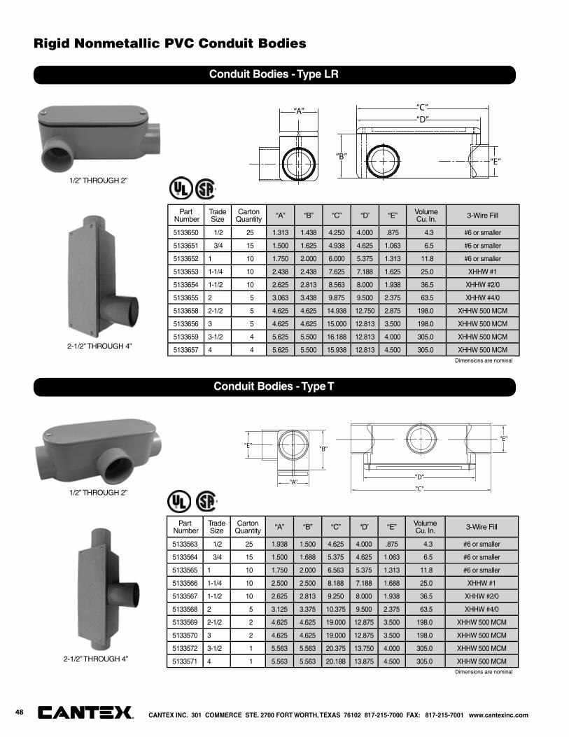
“A”
“B”
“C”“D”
“E”
Conduit Bodies - Type LR
Part Number
Trade Size
CartonQuantity “A” “B” “C” “D’ “E” Volume
Cu. In. 3-Wire Fill
5133650 1/2 25 1.313 1.438 4.250 4.000 .875 4.3 #6 or smaller
5133651 3/4 15 1.500 1.625 4.938 4.625 1.063 6.5 #6 or smaller
5133652 1 10 1.750 2.000 6.000 5.375 1.313 11.8 #6 or smaller
5133653 1-1/4 10 2.438 2.438 7.625 7.188 1.625 25.0 XHHW #1
5133654 1-1/2 10 2.625 2.813 8.563 8.000 1.938 36.5 XHHW #2/0
5133655 2 5 3.063 3.438 9.875 9.500 2.375 63.5 XHHW #4/0
5133658 2-1/2 5 4.625 4.625 14.938 12.750 2.875 198.0 XHHW 500 MCM
5133656 3 5 4.625 4.625 15.000 12.813 3.500 198.0 XHHW 500 MCM
5133659 3-1/2 4 5.625 5.500 16.188 12.813 4.000 305.0 XHHW 500 MCM
5133657 4 4 5.625 5.500 15.938 12.813 4.500 305.0 XHHW 500 MCM
"A""D"
"E"
"C"
"B""E"
Conduit Bodies - Type T
Part Number
Trade Size
CartonQuantity “A” “B” “C” “D’ “E” Volume
Cu. In. 3-Wire Fill
5133563 1/2 25 1.938 1.500 4.625 4.000 .875 4.3 #6 or smaller
5133564 3/4 15 1.500 1.688 5.375 4.625 1.063 6.5 #6 or smaller
5133565 1 10 1.750 2.000 6.563 5.375 1.313 11.8 #6 or smaller
5133566 1-1/4 10 2.500 2.500 8.188 7.188 1.688 25.0 XHHW #1
5133567 1-1/2 10 2.625 2.813 9.250 8.000 1.938 36.5 XHHW #2/0
5133568 2 5 3.125 3.375 10.375 9.500 2.375 63.5 XHHW #4/0
5133569 2-1/2 2 4.625 4.625 19.000 12.875 3.500 198.0 XHHW 500 MCM
5133570 3 2 4.625 4.625 19.000 12.875 3.500 198.0 XHHW 500 MCM
5133572 3-1/2 1 5.563 5.563 20.375 13.750 4.000 305.0 XHHW 500 MCM
5133571 4 1 5.563 5.563 20.188 13.875 4.500 305.0 XHHW 500 MCM
2-1/2” THROUGH 4”
2-1/2” THROUGH 4”
1/2” THROUGH 2”
1/2” THROUGH 2”
Dimensions are nominal
Dimensions are nominal
CANTEX INC. 301 COMMERCE STE. 2700 FORT WORTH, TEXAS 76102 817-215-7000 FAX: 817-215-7001 www.cantexinc.com®
Rigid Nonmetallic PVC Conduit Bodies
48
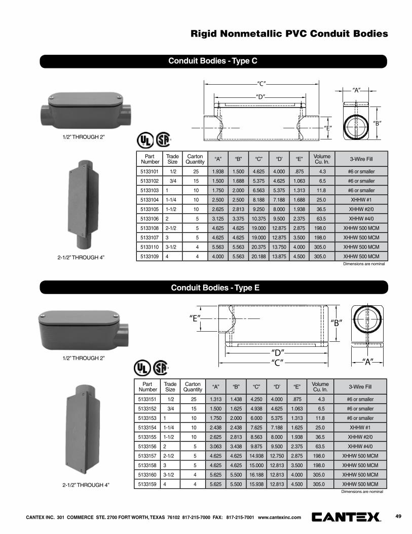
“A”
“B”
“C”“D”
“E”
Conduit Bodies - Type E
Part Number
Trade Size
CartonQuantity “A” “B” “C” “D’ “E” Volume
Cu. In. 3-Wire Fill
5133151 1/2 25 1.313 1.438 4.250 4.000 .875 4.3 #6 or smaller
5133152 3/4 15 1.500 1.625 4.938 4.625 1.063 6.5 #6 or smaller
5133153 1 10 1.750 2.000 6.000 5.375 1.313 11.8 #6 or smaller
5133154 1-1/4 10 2.438 2.438 7.625 7.188 1.625 25.0 XHHW #1
5133155 1-1/2 10 2.625 2.813 8.563 8.000 1.938 36.5 XHHW #2/0
5133156 2 5 3.063 3.438 9.875 9.500 2.375 63.5 XHHW #4/0
5133157 2-1/2 5 4.625 4.625 14.938 12.750 2.875 198.0 XHHW 500 MCM
5133158 3 5 4.625 4.625 15.000 12.813 3.500 198.0 XHHW 500 MCM
5133160 3-1/2 4 5.625 5.500 16.188 12.813 4.000 305.0 XHHW 500 MCM
5133159 4 4 5.625 5.500 15.938 12.813 4.500 305.0 XHHW 500 MCM
“A”
“B”
“C”
“D”
“E”
Conduit Bodies - Type C
Part Number
Trade Size
CartonQuantity “A” “B” “C” “D’ “E” Volume
Cu. In. 3-Wire Fill
5133101 1/2 25 1.938 1.500 4.625 4.000 .875 4.3 #6 or smaller
5133102 3/4 15 1.500 1.688 5.375 4.625 1.063 6.5 #6 or smaller
5133103 1 10 1.750 2.000 6.563 5.375 1.313 11.8 #6 or smaller
5133104 1-1/4 10 2.500 2.500 8.188 7.188 1.688 25.0 XHHW #1
5133105 1-1/2 10 2.625 2.813 9.250 8.000 1.938 36.5 XHHW #2/0
5133106 2 5 3.125 3.375 10.375 9.500 2.375 63.5 XHHW #4/0
5133108 2-1/2 5 4.625 4.625 19.000 12.875 2.875 198.0 XHHW 500 MCM
5133107 3 5 4.625 4.625 19.000 12.875 3.500 198.0 XHHW 500 MCM
5133110 3-1/2 4 5.563 5.563 20.375 13.750 4.000 305.0 XHHW 500 MCM
5133109 4 4 4.000 5.563 20.188 13.875 4.500 305.0 XHHW 500 MCM2-1/2” THROUGH 4”
1/2” THROUGH 2”
2-1/2” THROUGH 4”
1/2” THROUGH 2”
Dimensions are nominal
Dimensions are nominal
CANTEX INC. 301 COMMERCE STE. 2700 FORT WORTH, TEXAS 76102 817-215-7000 FAX: 817-215-7001 www.cantexinc.com 49®
Rigid Nonmetallic PVC Conduit Bodies
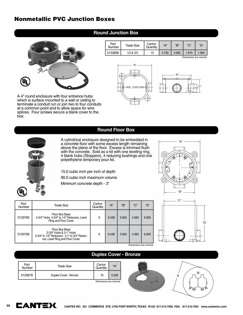
"B"
"C""D"VOL. 15.8 CU.IN.
"A"
Round Junction Box
Part Number Trade Size Carton
Quantity “A” “B” “C” “D’
5133690 1/2 & 3/4 15 4.750 4.063 1.875 1.063
A 4” round enclosure with four entrance hubs which is surface mounted to a wall or ceiling to terminate a conduit run or join two to four conduits at a common point and to allow space for wire splices. Four screws secure a blank cover to the box.
“D”
“C”
“B”
“A”
Round Floor Box
Part Number Trade Size Carton
Quantity “A” “B” “C” “D’
5133760Floor Box Base
4-3/4” Hubs, 4-3/4” to 1/2” Reducers, Level Ring and Pour Cover
9 6.438 3.563 4.563 6.000
5133758
Floor Box Base2-3/4” Hubs & 2-1” Hubs
2-3/4” to 1/2” Reducers , 2-1” to 3/4” Reduc-ers, Level Ring and Pour Cover
9 6.438 3.563 4.563 6.000
A cylindrical enclosure designed to be embedded in a concrete fl oor with some excess length remaining above the plane of the fl oor. Excess is trimmed fl ush with the concrete. Sold as a kit with one leveling ring, 4 blank hubs (Stoppers), 4 reducing bushings and one polyethylene temporary pour lid.
15.0 cubic inch per inch of depth
90.0 cubic inch maximum volume
Minimum concrete depth - 3”
Dimensions are nominal
Dimensions are nominal
Part Number Trade Size Carton
Quantity “A”
5133678 Duplex Cover - Bronze 10 5.500
Dimensions are nominal
A
Duplex Cover - Bronze
CANTEX INC. 201 COMMERCE STE. 2700 FORT WORTH, TEXAS 76102 817-215-7000 FAX: 817-215-7001 www.cantexinc.com
Nonmetallic PVC Junction Boxes
®50
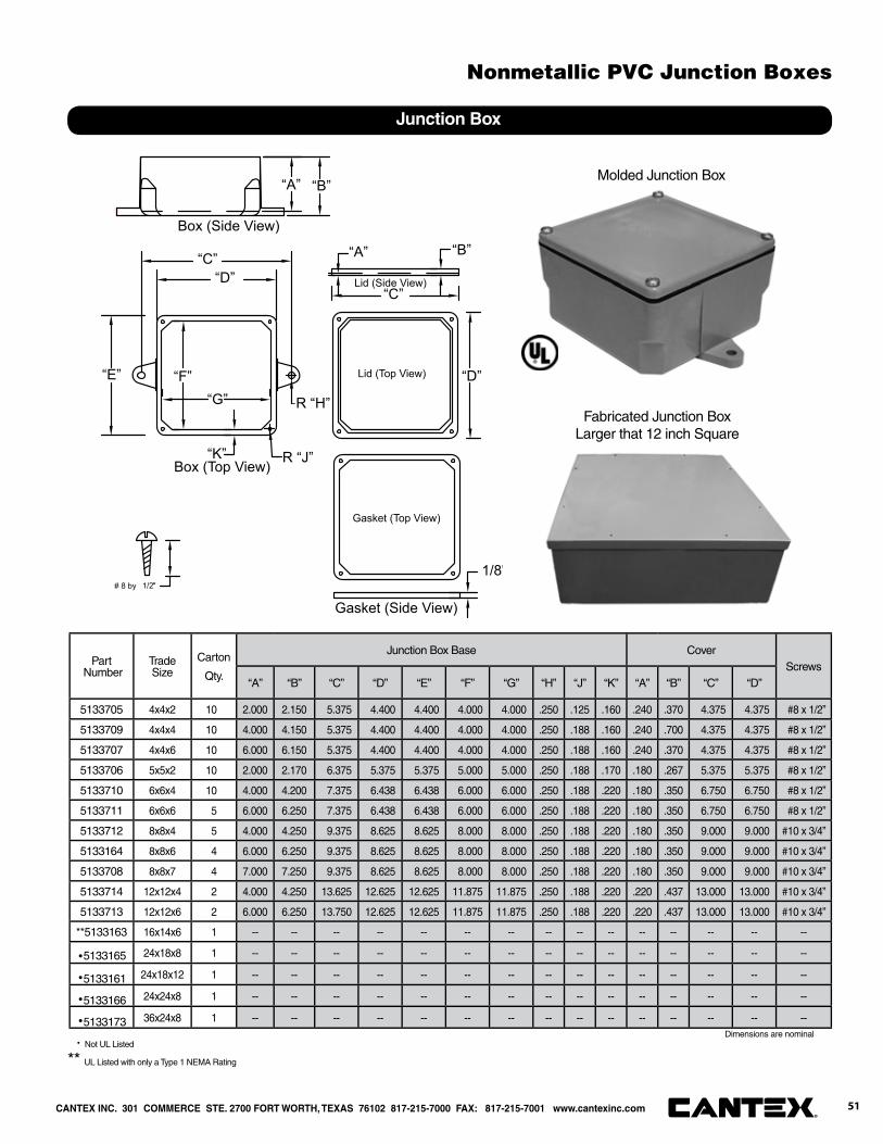
“B”
“C”“D”
“A”
“F”“G”
“K”
“E”
“C”
“D”
“A” “B”
Gasket (Top View)
Gasket (Side View)
Lid (Top View)
Lid (Side View)
Box (Top View)
Box (Side View)
1/8"
R “J”
R “H”
1/2"# 8 by
Junction Box
Part Number
Trade Size
Carton
Qty.
Junction Box Base CoverScrews
“A” “B” “C” “D” “E” “F” “G” “H” “J” “K” “A” “B” “C” “D”
5133705 4x4x2 10 2.000 2.150 5.375 4.400 4.400 4.000 4.000 .250 .125 .160 .240 .370 4.375 4.375 #8 x 1/2”
5133709 4x4x4 10 4.000 4.150 5.375 4.400 4.400 4.000 4.000 .250 .188 .160 .240 .700 4.375 4.375 #8 x 1/2”
5133707 4x4x6 10 6.000 6.150 5.375 4.400 4.400 4.000 4.000 .250 .188 .160 .240 .370 4.375 4.375 #8 x 1/2”
5133706 5x5x2 10 2.000 2.170 6.375 5.375 5.375 5.000 5.000 .250 .188 .170 .180 .267 5.375 5.375 #8 x 1/2”
5133710 6x6x4 10 4.000 4.200 7.375 6.438 6.438 6.000 6.000 .250 .188 .220 .180 .350 6.750 6.750 #8 x 1/2”
5133711 6x6x6 5 6.000 6.250 7.375 6.438 6.438 6.000 6.000 .250 .188 .220 .180 .350 6.750 6.750 #8 x 1/2”
5133712 8x8x4 5 4.000 4.250 9.375 8.625 8.625 8.000 8.000 .250 .188 .220 .180 .350 9.000 9.000 #10 x 3/4”
5133164 8x8x6 4 6.000 6.250 9.375 8.625 8.625 8.000 8.000 .250 .188 .220 .180 .350 9.000 9.000 #10 x 3/4”
5133708 8x8x7 4 7.000 7.250 9.375 8.625 8.625 8.000 8.000 .250 .188 .220 .180 .350 9.000 9.000 #10 x 3/4”
5133714 12x12x4 2 4.000 4.250 13.625 12.625 12.625 11.875 11.875 .250 .188 .220 .220 .437 13.000 13.000 #10 x 3/4”
5133713 12x12x6 2 6.000 6.250 13.750 12.625 12.625 11.875 11.875 .250 .188 .220 .220 .437 13.000 13.000 #10 x 3/4”
**5133163 16x14x6 1 -- -- -- -- -- -- -- -- -- -- -- -- -- -- --
·5133165 24x18x8 1 -- -- -- -- -- -- -- -- -- -- -- -- -- -- --
·5133161 24x18x12 1 -- -- -- -- -- -- -- -- -- -- -- -- -- -- --
·5133166 24x24x8 1 -- -- -- -- -- -- -- -- -- -- -- -- -- -- --
·5133173 36x24x8 1 -- -- -- -- -- -- -- -- -- -- -- -- -- -- --Dimensions are nominal
· Not UL Listed
** UL Listed with only a Type 1 NEMA Rating
Molded Junction Box
Fabricated Junction BoxLarger that 12 inch Square
CANTEX INC. 301 COMMERCE STE. 2700 FORT WORTH, TEXAS 76102 817-215-7000 FAX: 817-215-7001 www.cantexinc.com 51®
Nonmetallic PVC Junction Boxes


PVC Nonmetallic Exposed Boxes and Weatherproof Covers

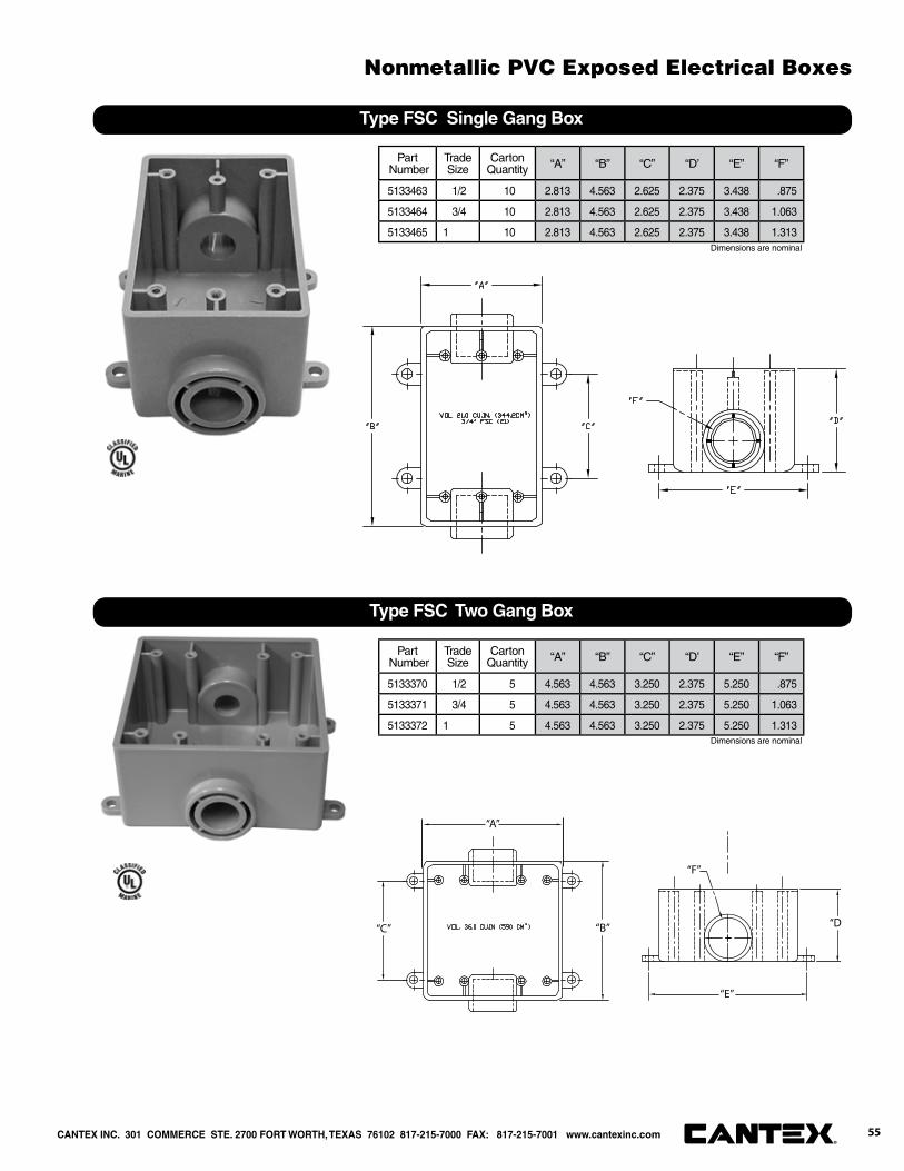
Type FSC Single Gang Box
Part Number
Trade Size
CartonQuantity “A” “B” “C” “D’ “E” “F”
5133463 1/2 10 2.813 4.563 2.625 2.375 3.438 .875
5133464 3/4 10 2.813 4.563 2.625 2.375 3.438 1.063
5133465 1 10 2.813 4.563 2.625 2.375 3.438 1.313
“A”
“B”“C” “D
“E”
“F”
Type FSC Two Gang Box
Part Number
Trade Size
CartonQuantity “A” “B” “C” “D’ “E” “F”
5133370 1/2 5 4.563 4.563 3.250 2.375 5.250 .875
5133371 3/4 5 4.563 4.563 3.250 2.375 5.250 1.063
5133372 1 5 4.563 4.563 3.250 2.375 5.250 1.313
Dimensions are nominal
Dimensions are nominal
CANTEX INC. 301 COMMERCE STE. 2700 FORT WORTH, TEXAS 76102 817-215-7000 FAX: 817-215-7001 www.cantexinc.com 55®
Nonmetallic PVC Exposed Electrical Boxes
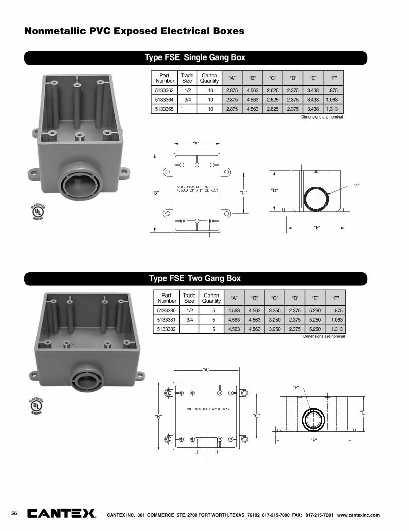
“A”
“B” “C” “D”
“E”
“F”
Type FSE Single Gang Box
Part Number
Trade Size
CartonQuantity “A” “B” “C” “D’ “E” “F”
5133363 1/2 10 2.875 4.563 2.625 2.375 3.438 .875
5133364 3/4 10 2.875 4.563 2.625 2.375 3.438 1.063
5133365 1 10 2.875 4.563 2.625 2.375 3.438 1.313
“A”
“B” “C” “D
“E”
“F”
Type FSE Two Gang Box
Part Number
Trade Size
CartonQuantity “A” “B” “C” “D’ “E” “F”
5133380 1/2 5 4.563 4.563 3.250 2.375 5.250 .875
5133381 3/4 5 4.563 4.563 3.250 2.375 5.250 1.063
5133382 1 5 4.563 4.563 3.250 2.375 5.250 1.313Dimensions are nominal
Dimensions are nominal
CANTEX INC. 301 COMMERCE STE. 2700 FORT WORTH, TEXAS 76102 817-215-7000 FAX: 817-215-7001 www.cantexinc.com®
Nonmetallic PVC Exposed Electrical Boxes
56
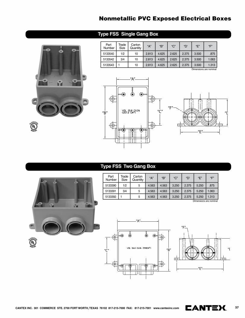
“A”
“B” “C” “D
“E”
“F”
Type FSS Single Gang Box
Part Number
Trade Size
CartonQuantity “A” “B” “C” “D’ “E” “F”
5133540 1/2 10 2.813 4.625 2.625 2.375 3.500 .875
5133542 3/4 10 2.813 4.625 2.625 2.375 3.500 1.063
5133543 1 10 2.813 4.625 2.625 2.375 3.500 1.313
“A”
“B”“C” “D
“E”
“F”
Type FSS Two Gang Box
Part Number
Trade Size
CartonQuantity “A” “B” “C” “D’ “E” “F”
5133390 1/2 5 4.563 4.563 3.250 2.375 5.250 .875
5133391 3/4 5 4.563 4.563 3.250 2.375 5.250 1.063
5133392 1 5 4.563 4.563 3.250 2.375 5.250 1.313Dimensions are nominal
Dimensions are nominal
CANTEX INC. 301 COMMERCE STE. 2700 FORT WORTH, TEXAS 76102 817-215-7000 FAX: 817-215-7001 www.cantexinc.com 57®
Nonmetallic PVC Exposed Electrical Boxes
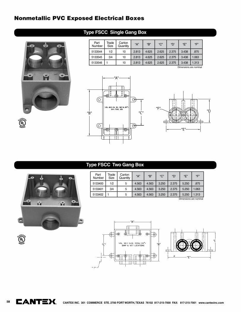
“A”
“D“B” “C”
“E”
“F”
Type FSCC Single Gang Box
Part Number
Trade Size
CartonQuantity “A” “B” “C” “D’ “E” “F”
5133544 1/2 10 2.813 4.625 2.625 2.375 3.438 .875
5133545 3/4 10 2.813 4.625 2.625 2.375 3.438 1.063
5133546 1 10 2.813 4.625 2.625 2.375 3.438 1.313
“A”
“B”“C”“D
“E”
Type FSCC Two Gang Box
Part Number
Trade Size
CartonQuantity “A” “B” “C” “D’ “E” “F”
5133400 1/2 5 4.563 4.563 3.250 2.375 5.250 .875
5133401 3/4 5 4.563 4.563 3.250 2.375 5.250 1.063
5133402 1 5 4.563 4.563 3.250 2.375 5.250 1.313
Dimensions are nominal
Dimensions are nominal
CANTEX INC. 301 COMMERCE STE. 2700 FORT WORTH, TEXAS 76102 817-215-7000 FAX: 817-215-7001 www.cantexinc.com®
Nonmetallic PVC Exposed Electrical Boxes
58

"B" "D""C"
"E"
"A"
VOL 21.0 CU.IN. (344.2CM )3/4" FSC (21)
3
"F"
Type FDC Single Gang Box
Part Number
Trade Size
CartonQuantity “A” “B” “C” “D’ “E” “F”
5133310 1/2 10 2.563 4.563 2.625 2.938 3.500 .875
5133311 3/4 10 2.563 4.563 2.625 2.938 3.500 1.063
5133312 1 10 2.563 4.563 2.625 2.938 3.500 1.313
“A”
“B”“C” “D”
“E”
Type FDE Single Gang Box
Part Number
Trade Size
CartonQuantity “A” “B” “C” “D’ “E”
5133300 1/2 10 2.688 5.875 4.500 2.875 .875
5133301 3/4 10 2.688 5.875 4.500 2.875 1.063
5133302 1 10 2.688 5.875 4.500 2.875 1.313
Dimensions are nominal
Dimensions are nominal
CANTEX INC. 301 COMMERCE STE. 2700 FORT WORTH, TEXAS 76102 817-215-7000 FAX: 817-215-7001 www.cantexinc.com 59®
Nonmetallic PVC Exposed Electrical Boxes
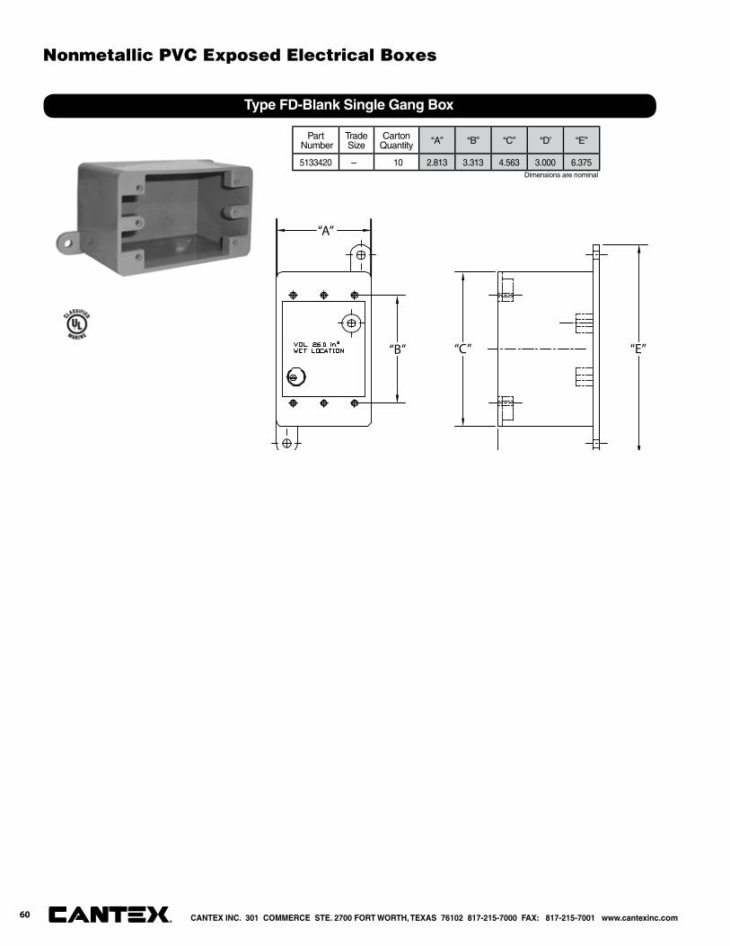
“A”
“B” “C” “E”
Type FD-Blank Single Gang Box
Part Number
Trade Size
CartonQuantity “A” “B” “C” “D’ “E”
5133420 -- 10 2.813 3.313 4.563 3.000 6.375Dimensions are nominal
CANTEX INC. 301 COMMERCE STE. 2700 FORT WORTH, TEXAS 76102 817-215-7000 FAX: 817-215-7001 www.cantexinc.com®
Nonmetallic PVC Exposed Electrical Boxes
60
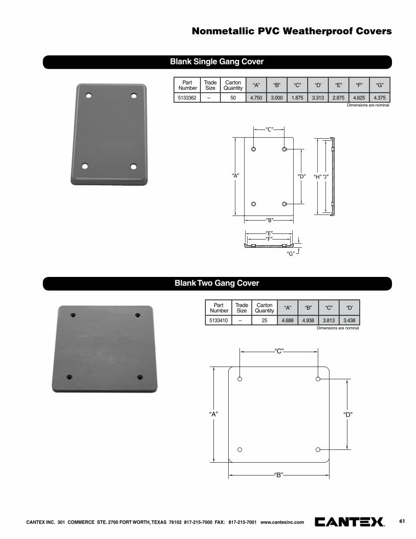
“A”
“B”
“C”
“D”
“E”“F”
“G”
“J”“H”
Blank Single Gang Cover
Part Number
Trade Size
CartonQuantity “A” “B” “C” “D’ “E” “F” “G”
5133362 -- 50 4.750 3.000 1.875 3.313 2.875 4.625 4.375
“A”
“B”
“C”
“D”
Blank Two Gang Cover
Part Number
Trade Size
CartonQuantity “A” “B” “C” “D’
5133410 -- 25 4.688 4.938 3.813 3.438
Dimensions are nominal
Dimensions are nominal
CANTEX INC. 301 COMMERCE STE. 2700 FORT WORTH, TEXAS 76102 817-215-7000 FAX: 817-215-7001 www.cantexinc.com 61®
Nonmetallic PVC Weatherproof Covers
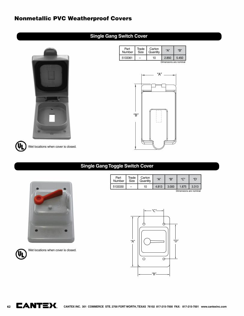
“A”
“B”
Single Gang Switch Cover
Part Number
Trade Size
CartonQuantity “A” “B”
5133361 -- 10 2.850 5.450
“A”
“B”
“C”
“D”
Single Gang Toggle Switch Cover
Part Number
Trade Size
CartonQuantity “A” “B” “C” “D’
5133330 -- 10 4.813 3.000 1.875 3.313
Dimensions are nominal
Dimensions are nominal
Wet locations when cover is closed.
Wet locations when cover is closed.
CANTEX INC. 301 COMMERCE STE. 2700 FORT WORTH, TEXAS 76102 817-215-7000 FAX: 817-215-7001 www.cantexinc.com®
Nonmetallic PVC Weatherproof Covers
62
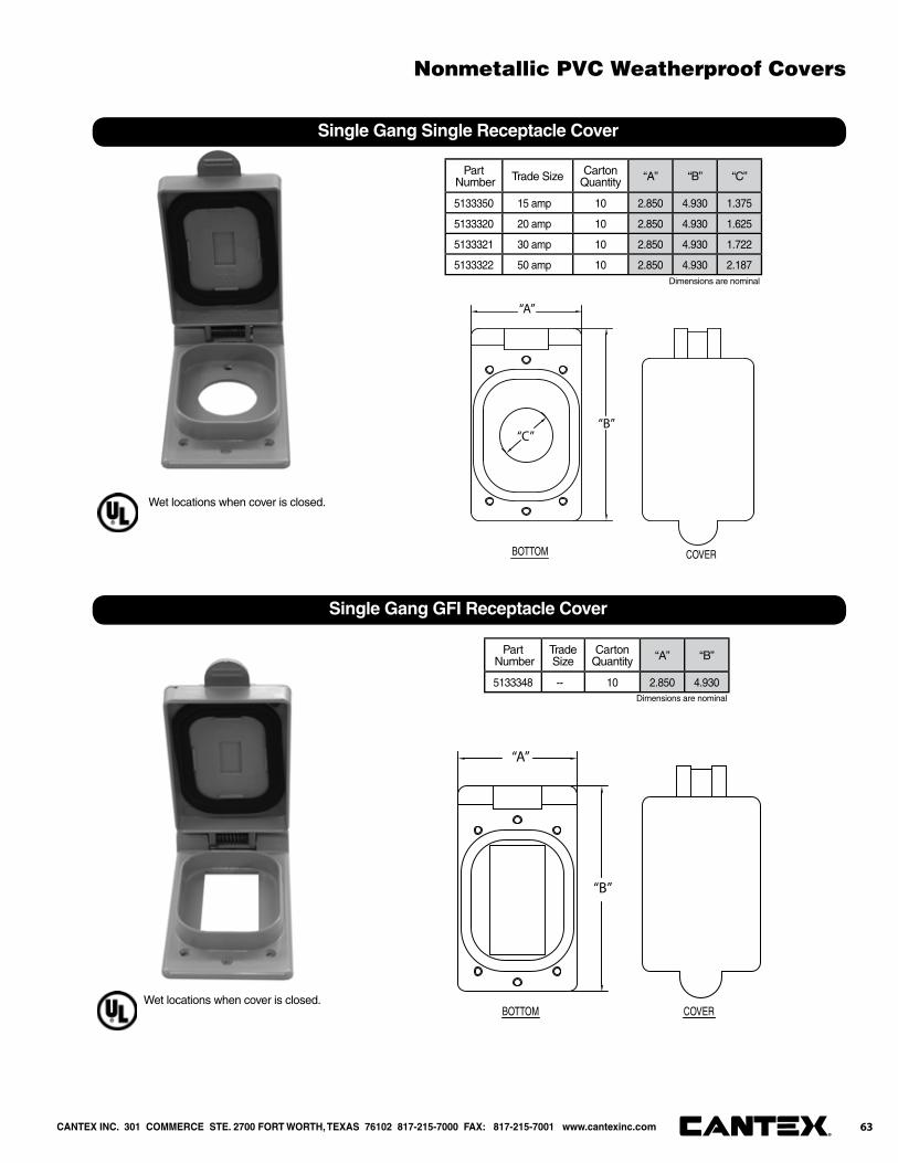
BOTTOM COVER
“A”
“B”“C”
Single Gang Single Receptacle Cover
Part Number Trade Size Carton
Quantity “A” “B” “C”
5133350 15 amp 10 2.850 4.930 1.375
5133320 20 amp 10 2.850 4.930 1.625
5133321 30 amp 10 2.850 4.930 1.722
5133322 50 amp 10 2.850 4.930 2.187
BOTTOM COVER
“A”
“B”
Single Gang GFI Receptacle Cover
Part Number
Trade Size
CartonQuantity “A” “B”
5133348 -- 10 2.850 4.930
Dimensions are nominal
Dimensions are nominal
Wet locations when cover is closed.
Wet locations when cover is closed.
CANTEX INC. 301 COMMERCE STE. 2700 FORT WORTH, TEXAS 76102 817-215-7000 FAX: 817-215-7001 www.cantexinc.com®
Nonmetallic PVC Weatherproof Covers
63

BOTTOM COVER
“A”
“B”
Single Gang Duplex Receptacle Cover
Part Number
Trade Size
CartonQuantity “A” “B”
5133352 -- 10 2.850 4.930
“A”
“B”
“C”
“D”
“E”
Single Gang Plunger Switch Cover
Part Number
Trade Size
CartonQuantity “A” “B” “C” “D’ “E”
5133335 -- 10 4.813 6.250 3.000 1.875 3.313
Dimensions are nominal
Dimensions are nominal
Wet locations when cover is closed.
Wet locations when cover is closed.
CANTEX INC. 301 COMMERCE STE. 2700 FORT WORTH, TEXAS 76102 817-215-7000 FAX: 817-215-7001 www.cantexinc.com®
Nonmetallic PVC Weatherproof Covers
64
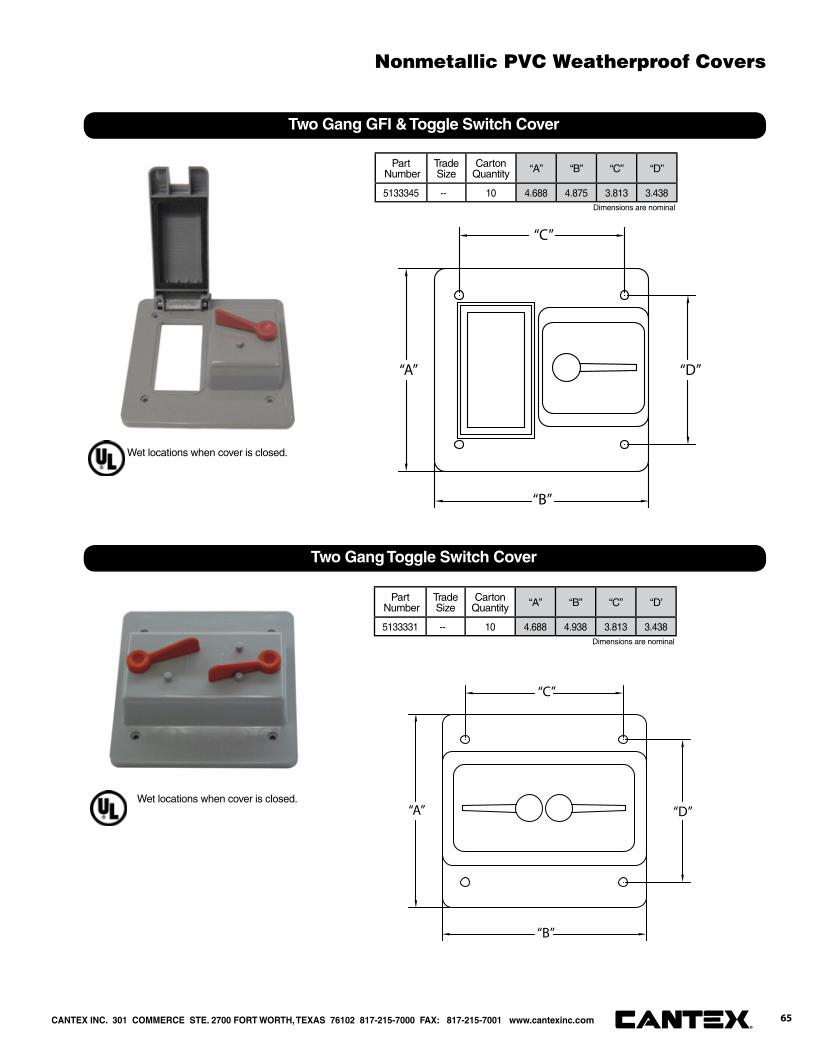
“A”
“B”
“C”
“D”
Two Gang GFI & Toggle Switch Cover
Part Number
Trade Size
CartonQuantity “A” “B” “C” “D”
5133345 -- 10 4.688 4.875 3.813 3.438
“A”
“B”
“C”
“D”
Two Gang Toggle Switch Cover
Part Number
Trade Size
CartonQuantity “A” “B” “C” “D’
5133331 -- 10 4.688 4.938 3.813 3.438Dimensions are nominal
Dimensions are nominal
Wet locations when cover is closed.
Wet locations when cover is closed.
CANTEX INC. 301 COMMERCE STE. 2700 FORT WORTH, TEXAS 76102 817-215-7000 FAX: 817-215-7001 www.cantexinc.com 65®
Nonmetallic PVC Weatherproof Covers
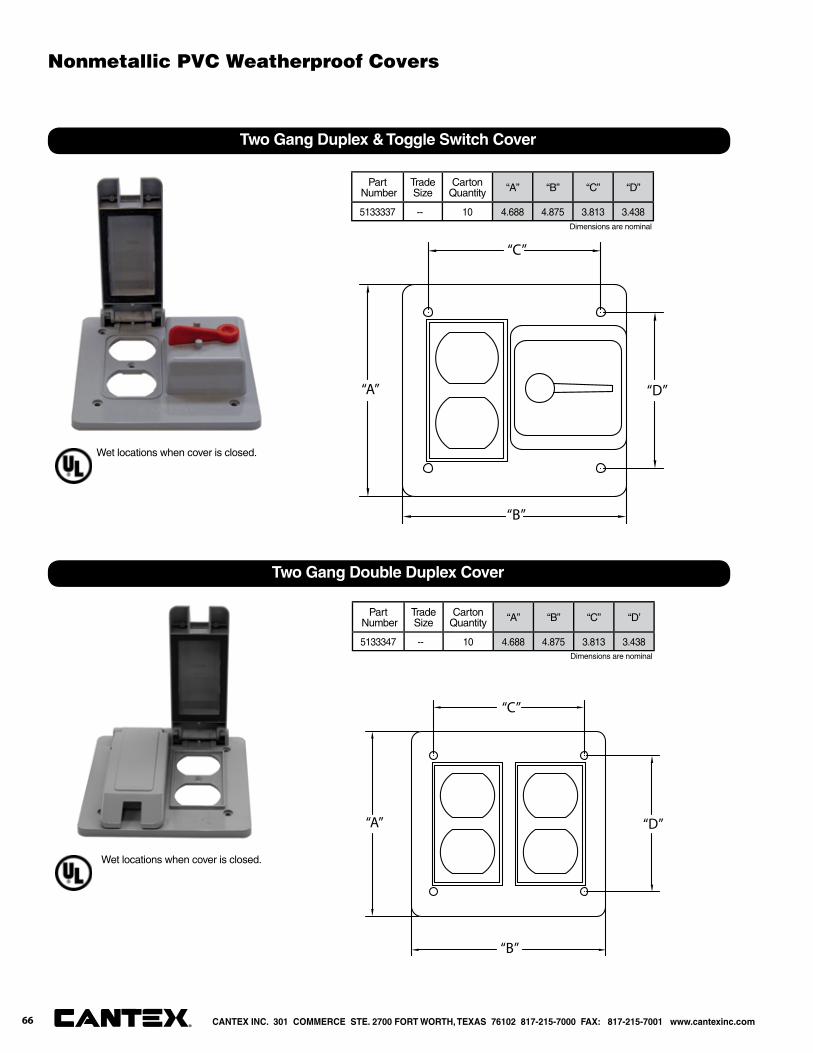
“A”
“B”
“C”
“D”
Two Gang Duplex & Toggle Switch Cover
Part Number
Trade Size
CartonQuantity “A” “B” “C” “D”
5133337 -- 10 4.688 4.875 3.813 3.438
“A”
“B”
“C”
“D”
Two Gang Double Duplex Cover
Part Number
Trade Size
CartonQuantity “A” “B” “C” “D’
5133347 -- 10 4.688 4.875 3.813 3.438
Dimensions are nominal
Dimensions are nominal
Wet locations when cover is closed.
Wet locations when cover is closed.
CANTEX INC. 301 COMMERCE STE. 2700 FORT WORTH, TEXAS 76102 817-215-7000 FAX: 817-215-7001 www.cantexinc.com®
Nonmetallic PVC Weatherproof Covers
66
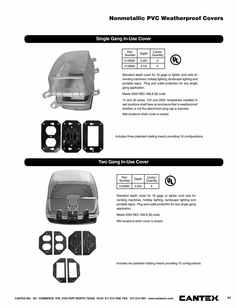
Single Gang In-Use Cover
Part Number Depth Carton
Quantity
5133692 2.250 6
5133694 3.125 6
Two Gang In-Use Cover
Part Number Depth Carton
Quantity
5133693 2.250 6
Standard depth cover for 16 gage or lighter cord sets for vending machines, holiday lighting, landscape lighting and portable signs. Plug and outlet protection for any single gang application.
Meets 2005 NEC 406.8 (B) code.
15 and 20 amps, 125 and 250V receptacles installed in wet locations shall have an enclosure that is weatherproof whether or not the attachment plug cap is inserted.
Standard depth cover for 16 gage or lighter cord sets for vending machines, holiday lighting, landscape lighting and portable signs. Plug and outlet protection for any single gang application.
Meets 2005 NEC 406.8 (B) code.
Includes three patented rotating inserts providing 16 confi gurations
Includes six patented rotating inserts providing 70 confi gurations
Wet locations when cover is closed.
Wet locations when cover is closed.
CANTEX INC. 301 COMMERCE STE. 2700 FORT WORTH, TEXAS 76102 817-215-7000 FAX: 817-215-7001 www.cantexinc.com 67®
Nonmetallic PVC Weatherproof Covers

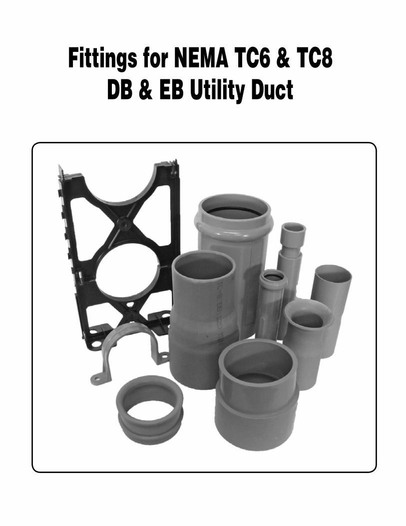
Fittings for NEMA TC6 & TC8 DB & EB Utility Duct

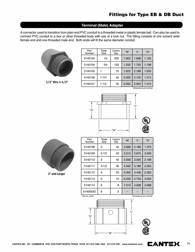
A connector used to transition from plain end PVC conduit to a threaded metal or plastic female bell. Can also be used to connect PVC conduit to a box or other threaded body with use of a lock nut. The fi tting consists of one solvent weld female end and one threaded male end. Both ends will fi t the same diameter conduit.
"W"
"L"
"D"
"W"
"L"
"D"
Terminal (Male) Adapter
Dimensions are nominal
Dimensions are nominal * Not UL Listed
Part Number
Trade Size
Carton Qty. “W’ “L” “D”
5140103 1/2 200 1.063 1.688 1.125
5140104 3/4 125 1.250 1.750 1.188
5140105 1 70 1.625 2.188 1.500
5140106 1-1/4 40 2.000 2.125 1.313
5140107 1-1/2 30 2.000 2.063 1.313
Part Number
Trade Size
Carton Qty. “W’ “L” “D”
5140108 2 40 2.688 2.188 1.375
5140109 2-1/2 20 3.313 2.875 2.000
5140110 3 40 3.938 3.000 2.188
5140111 3-1/2 30 4.500 3.188 2.563
5140112 4 20 5.000 3.438 2.563
5140113 5 10 6.250 4.750 3.000
5140114 6 8 7.313 4.938 2.688
5140055D 8 2 -- -- --
CANTEX INC. 301 COMMERCE STE. 2700 FORT WORTH, TEXAS 76102 817-215-7000 FAX: 817-215-7001 www.cantexinc.com 71®
Fittings for Type EB & DB Duct
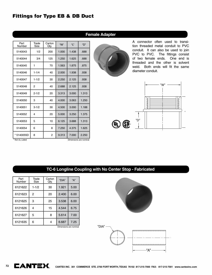
Part Number
Trade Size
Carton Qty. “W’ “L” “D”
5140043 1/2 200 1.000 1.438 .688
5140044 3/4 125 1.250 1.625 .688
5140045 1 70 1.563 1.875 .875
5140046 1-1/4 40 2.000 1.938 .938
5140047 1-1/2 30 2.250 2.125 .938
5140048 2 40 2.688 2.125 .938
5140049 2-1/2 20 3.313 3.000 1.313
5140050 3 40 4.000 3.063 1.250
5140051 3-1/2 30 4.500 3.000 1.188
5140052 4 20 5.000 3.250 1.375
5140053 5 10 6.125 3.688 1.313
5140054 6 8 7.250 4.375 1.625
* 5140055D 8 2 9.313 7.000 2.250
A connector often used to transi-tion threaded metal conduit to PVC conduit. It can also be used to join PVC to PVC. The fi ttings consist of two female ends. One end is threaded and the other is solvent weld. Both ends will fi t the samediameter conduit.
"W"
"
"D"
Female Adapter
Part Number
Trade Size
Carton Qty. “DIA” “A”
6121622 1-1/2 30 1.921 5.00
6121623 2 20 2.400 6.00
6121625 3 25 3.538 6.00
6121626 4 15 4.544 6.75
6121627 5 8 5.614 7.00
6121635 6 4 6.687 7.25
TC-6 Longline Coupling with No Center Stop - Fabricated
"DIA"
"A"
Dimensions are nominal
Dimensions are nominal
* Not UL Listed
CANTEX INC. 301 COMMERCE STE. 2700 FORT WORTH, TEXAS 76102 817-215-7000 FAX: 817-215-7001 www.cantexinc.com®
Fittings for Type EB & DB Duct
72
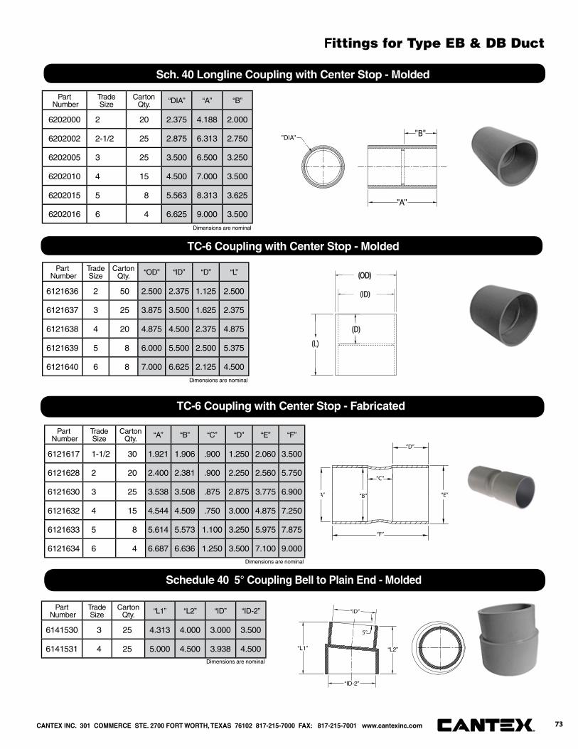
Part Number
Trade Size
Carton Qty. “DIA” “A” “B”
6202000 2 20 2.375 4.188 2.000
6202002 2-1/2 25 2.875 6.313 2.750
6202005 3 25 3.500 6.500 3.250
6202010 4 15 4.500 7.000 3.500
6202015 5 8 5.563 8.313 3.625
6202016 6 4 6.625 9.000 3.500
Sch. 40 Longline Coupling with Center Stop - Molded
"DIA"
"A"
"B"
Part Number
Trade Size
Carton Qty. “OD” “ID” “D” “L”
6121636 2 50 2.500 2.375 1.125 2.500
6121637 3 25 3.875 3.500 1.625 2.375
6121638 4 20 4.875 4.500 2.375 4.875
6121639 5 8 6.000 5.500 2.500 5.375
6121640 6 8 7.000 6.625 2.125 4.500
TC-6 Coupling with Center Stop - Molded
(OD)
(ID)
(D)
(L)
Part Number
Trade Size
Carton Qty. “A” “B” “C” “D” “E” “F”
6121617 1-1/2 30 1.921 1.906 .900 1.250 2.060 3.500
6121628 2 20 2.400 2.381 .900 2.250 2.560 5.750
6121630 3 25 3.538 3.508 .875 2.875 3.775 6.900
6121632 4 15 4.544 4.509 .750 3.000 4.875 7.250
6121633 5 8 5.614 5.573 1.100 3.250 5.975 7.875
6121634 6 4 6.687 6.636 1.250 3.500 7.100 9.000
TC-6 Coupling with Center Stop - Fabricated
A” “B”
“C”
“D”
“E”
“F”
Part Number
Trade Size
Carton Qty. “L1” “L2” “ID” “ID-2”
6141530 3 25 4.313 4.000 3.000 3.500
6141531 4 25 5.000 4.500 3.938 4.500
Schedule 40 5° Coupling Bell to Plain End - Molded
“ID”
5°
“L2”
“ID-2”
“L1”
Dimensions are nominal
Dimensions are nominal
Dimensions are nominal
Dimensions are nominal
CANTEX INC. 301 COMMERCE STE. 2700 FORT WORTH, TEXAS 76102 817-215-7000 FAX: 817-215-7001 www.cantexinc.com 73®
Fittings for Type EB & DB Duct

Part Number
Trade Size
Carton Qty. “L1” “L2” “BE” “BB” “D”
Min
6151457 2 20 6.250 6.000 2.400 2.381 1.750
6151458 3 25 7.500 7.188 3.538 3.508 2.875
6151459 4 15 8.750 8.375 4.544 4.509 3.375
6151460 5 8 10.500 10.000 5.614 5.573 4.000
6151461 6 4 13.000 12.438 6.687 6.636 5.000
TC6 5° Coupling Bell to Bell End - Fabricated
5°
“BB”
“L2”
“BE”
“ D MIN”
“L1”
Part Number
Trade Size
Carton Qty. “L” “ID” “ID-2” “DIA”
5142210 3x2 25 7.250 2.250 3.563 3.688
5142211 5x4 8 9.250 4.188 5.563 5.813
5142209 6x5 4 9.250 5.250 6.625 6.938
TC-6 Swedged Reducer - Bell to Plain End - Fabricated
"ID"
"L"
"ØDIA"
"ID-2"
Part Number
Trade Size
Carton Qty. “L” “ID” “ID-2” “ID-3” “DIA”
5142212 4x3 15 9.000 3.563 3.250 4.500 4.750
TC-6 Swedged Reducer - Bell to Bell End - Fabricated
“ DIA”
“ID”
“ID-2”
“ID-3”
“L”
Part Number
Trade Size
Carton Qty. “L” “ID” “OD” “SD”
5124010 2 40 6.00 2.375 2.500 2.125
5124012 3 50 6.125 3.500 3.750 3.375
5124014 4 50 6.125 4.500 4.875 4.000
5124015 5 25 7.125 5.500 5.875 5.125
5124017 6 15 7.000 6.625 7.000 6.000
TC-6 End Bells - Fabricated
"L"
"OD"
"ID"
"SD"
18
Dimensions are nominal
Dimensions are nominal
Dimensions are nominal
Dimensions are nominal
CANTEX INC. 301 COMMERCE STE. 2700 FORT WORTH, TEXAS 76102 817-215-7000 FAX: 817-215-7001 www.cantexinc.com®
Fittings for Type EB & DB Duct
74
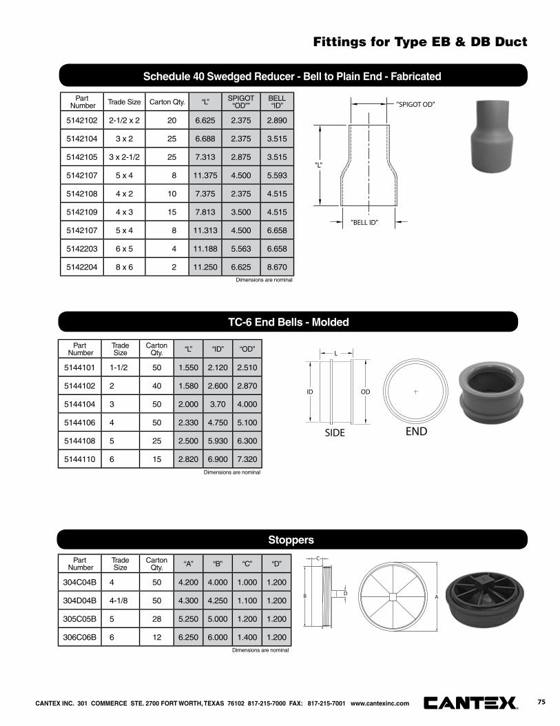
Part Number Trade Size Carton Qty. “L” SPIGOT
“OD””BELL“ID”
5142102 2-1/2 x 2 20 6.625 2.375 2.890
5142104 3 x 2 25 6.688 2.375 3.515
5142105 3 x 2-1/2 25 7.313 2.875 3.515
5142107 5 x 4 8 11.375 4.500 5.593
5142108 4 x 2 10 7.375 2.375 4.515
5142109 4 x 3 15 7.813 3.500 4.515
5142107 5 x 4 8 11.313 4.500 6.658
5142203 6 x 5 4 11.188 5.563 6.658
5142204 8 x 6 2 11.250 6.625 8.670
Schedule 40 Swedged Reducer - Bell to Plain End - Fabricated
"BELL ID"
"L"
"SPIGOT OD"
Part Number
Trade Size
Carton Qty. “L” “ID” “OD”
5144101 1-1/2 50 1.550 2.120 2.510
5144102 2 40 1.580 2.600 2.870
5144104 3 50 2.000 3.70 4.000
5144106 4 50 2.330 4.750 5.100
5144108 5 25 2.500 5.930 6.300
5144110 6 15 2.820 6.900 7.320
TC-6 End Bells - Molded
L
ODID
SIDE END
Part Number
Trade Size
Carton Qty. “A” “B” “C” “D”
304C04B 4 50 4.200 4.000 1.000 1.200
304D04B 4-1/8 50 4.300 4.250 1.100 1.200
305C05B 5 28 5.250 5.000 1.200 1.200
306C06B 6 12 6.250 6.000 1.400 1.200
Stoppers
A
C
B D
Dimensions are nominal
Dimensions are nominal
Dimensions are nominal
CANTEX INC. 301 COMMERCE STE. 2700 FORT WORTH, TEXAS 76102 817-215-7000 FAX: 817-215-7001 www.cantexinc.com 75®
Fittings for Type EB & DB Duct
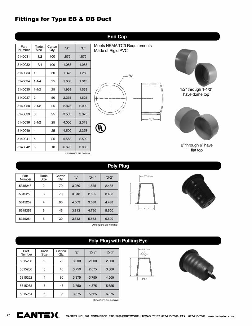
Poly Plug
Ø"D-2"
"L"
Ø"D-1"Part Number
TradeSize
Carton Qty. “L” “D-1” “D-2”
5315248 2 70 3.250 1.875 2.438
5315250 3 70 3.813 2.625 3.438
5315252 4 90 4.063 3.688 4.438
5315253 5 45 3.813 4.750 5.500
5315254 6 30 3.813 5.563 6.500
Poly Plug with Pulling Eye
Ø"D-2"
"L"
Ø"D-1"Part
NumberTradeSize
Carton Qty. “L” “D-1” “D-2”
5315258 2 70 3.000 2.000 2.500
5315260 3 45 3.750 2.875 3.500
5315262 4 80 3.875 3.750 4.500
5315263 5 45 3.750 4.875 5.625
5315264 6 35 3.875 5.625 6.875
Part Number
Trade Size
Carton Qty. “A” “B”
5140031 1/2 100 .875 .875
5140032 3/4 100 1.063 1.063
5140033 1 50 1.375 1.250
5140034 1-1/4 25 1.688 1.313
5140035 1-1/2 25 1.938 1.563
5140037 2 50 2.375 1.625
5140038 2-1/2 25 2.875 2.000
5140039 3 25 3.563 2.375
5140036 3-1/2 25 4.000 2.313
5140040 4 25 4.500 2.375
5140041 5 25 5.563 2.500
5140042 6 10 6.625 3.000
Meets NEMA TC3 RequirementsMade of Rigid PVC
End Cap
"B"
"A"
Dimensions are nominal
Dimensions are nominal
Dimensions are nominal
1/2” through 1-1/2” have dome top
2” through 6” have fl at top
CANTEX INC. 301 COMMERCE STE. 2700 FORT WORTH, TEXAS 76102 817-215-7000 FAX: 817-215-7001 www.cantexinc.com®
Fittings for Type EB & DB Duct
76
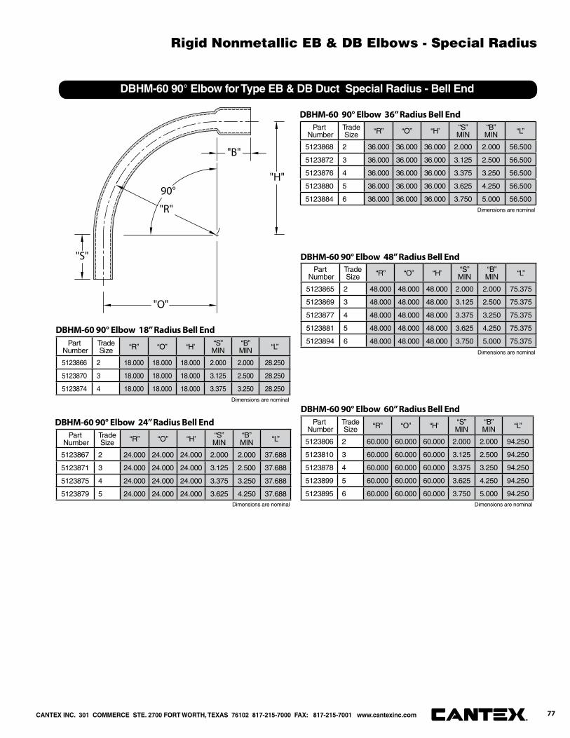
90°
"O"
"B"
"R"
"S"
"H"
DBHM-60 90° Elbow for Type EB & DB Duct Special Radius - Bell End
Part Number
Trade Size “R” “O” “H’ “S”
MIN“B”MIN “L”
5123866 2 18.000 18.000 18.000 2.000 2.000 28.250
5123870 3 18.000 18.000 18.000 3.125 2.500 28.250
5123874 4 18.000 18.000 18.000 3.375 3.250 28.250
DBHM-60 90° Elbow 18” Radius Bell End
Part Number
Trade Size “R” “O” “H’ “S”
MIN“B”MIN “L”
5123867 2 24.000 24.000 24.000 2.000 2.000 37.688
5123871 3 24.000 24.000 24.000 3.125 2.500 37.688
5123875 4 24.000 24.000 24.000 3.375 3.250 37.688
5123879 5 24.000 24.000 24.000 3.625 4.250 37.688
DBHM-60 90° Elbow 24” Radius Bell End
Part Number
Trade Size “R” “O” “H’ “S”
MIN“B”MIN “L”
5123868 2 36.000 36.000 36.000 2.000 2.000 56.500
5123872 3 36.000 36.000 36.000 3.125 2.500 56.500
5123876 4 36.000 36.000 36.000 3.375 3.250 56.500
5123880 5 36.000 36.000 36.000 3.625 4.250 56.500
5123884 6 36.000 36.000 36.000 3.750 5.000 56.500
DBHM-60 90° Elbow 36” Radius Bell End
Part Number
Trade Size “R” “O” “H’ “S”
MIN“B”MIN “L”
5123865 2 48.000 48.000 48.000 2.000 2.000 75.375
5123869 3 48.000 48.000 48.000 3.125 2.500 75.375
5123877 4 48.000 48.000 48.000 3.375 3.250 75.375
5123881 5 48.000 48.000 48.000 3.625 4.250 75.375
5123894 6 48.000 48.000 48.000 3.750 5.000 75.375
DBHM-60 90° Elbow 48” Radius Bell End
Part Number
Trade Size “R” “O” “H’ “S”
MIN“B”MIN “L”
5123806 2 60.000 60.000 60.000 2.000 2.000 94.250
5123810 3 60.000 60.000 60.000 3.125 2.500 94.250
5123878 4 60.000 60.000 60.000 3.375 3.250 94.250
5123899 5 60.000 60.000 60.000 3.625 4.250 94.250
5123895 6 60.000 60.000 60.000 3.750 5.000 94.250
DBHM-60 90° Elbow 60” Radius Bell End
Dimensions are nominal
Dimensions are nominal
Dimensions are nominal Dimensions are nominal
Dimensions are nominal
CANTEX INC. 301 COMMERCE STE. 2700 FORT WORTH, TEXAS 76102 817-215-7000 FAX: 817-215-7001 www.cantexinc.com 77®
Rigid Nonmetallic EB & DB Elbows - Special Radius
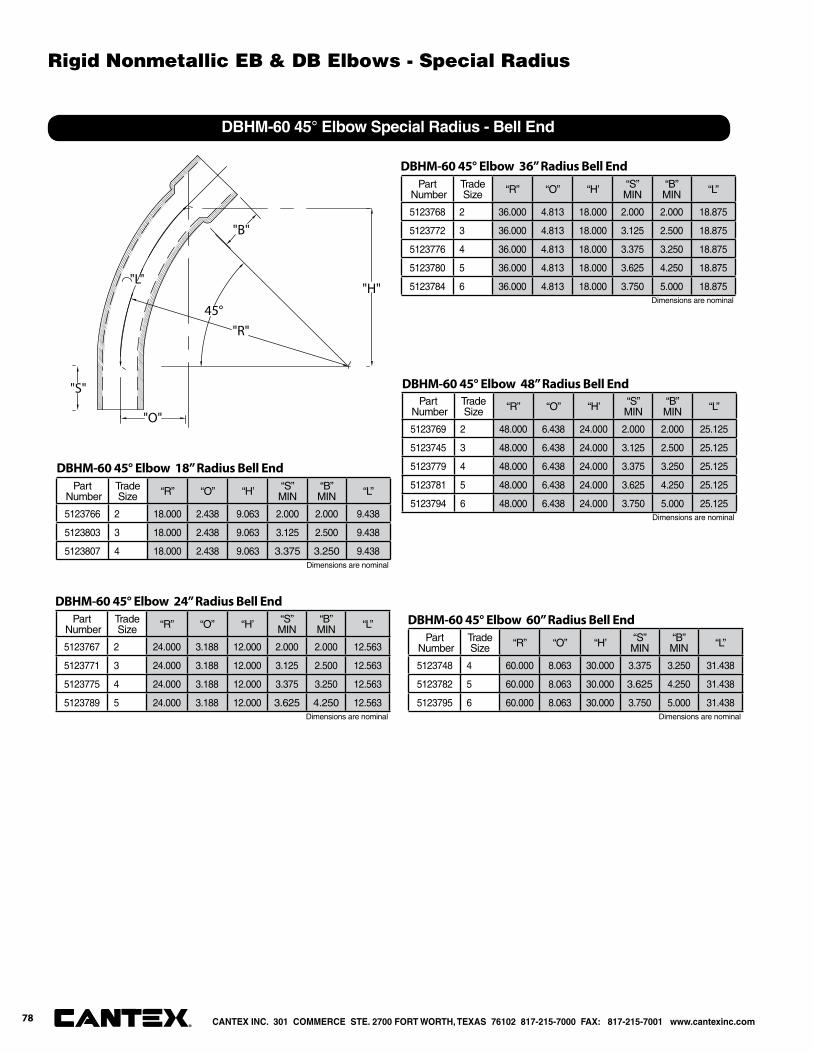
45°
"B"
"O"
"H""L"
"S"
"R"
DBHM-60 45° Elbow Special Radius - Bell End
Part Number
Trade Size “R” “O” “H’ “S”
MIN“B”MIN “L”
5123766 2 18.000 2.438 9.063 2.000 2.000 9.438
5123803 3 18.000 2.438 9.063 3.125 2.500 9.438
5123807 4 18.000 2.438 9.063 3.375 3.250 9.438
DBHM-60 45° Elbow 18” Radius Bell End
Part Number
Trade Size “R” “O” “H’ “S”
MIN“B”MIN “L”
5123767 2 24.000 3.188 12.000 2.000 2.000 12.563
5123771 3 24.000 3.188 12.000 3.125 2.500 12.563
5123775 4 24.000 3.188 12.000 3.375 3.250 12.563
5123789 5 24.000 3.188 12.000 3.625 4.250 12.563
DBHM-60 45° Elbow 24” Radius Bell End
Part Number
Trade Size “R” “O” “H’ “S”
MIN“B”MIN “L”
5123768 2 36.000 4.813 18.000 2.000 2.000 18.875
5123772 3 36.000 4.813 18.000 3.125 2.500 18.875
5123776 4 36.000 4.813 18.000 3.375 3.250 18.875
5123780 5 36.000 4.813 18.000 3.625 4.250 18.875
5123784 6 36.000 4.813 18.000 3.750 5.000 18.875
DBHM-60 45° Elbow 36” Radius Bell End
Part Number
Trade Size “R” “O” “H’ “S”
MIN“B”MIN “L”
5123769 2 48.000 6.438 24.000 2.000 2.000 25.125
5123745 3 48.000 6.438 24.000 3.125 2.500 25.125
5123779 4 48.000 6.438 24.000 3.375 3.250 25.125
5123781 5 48.000 6.438 24.000 3.625 4.250 25.125
5123794 6 48.000 6.438 24.000 3.750 5.000 25.125
DBHM-60 45° Elbow 48” Radius Bell End
Part Number
Trade Size “R” “O” “H’ “S”
MIN“B”MIN “L”
5123748 4 60.000 8.063 30.000 3.375 3.250 31.438
5123782 5 60.000 8.063 30.000 3.625 4.250 31.438
5123795 6 60.000 8.063 30.000 3.750 5.000 31.438
DBHM-60 45° Elbow 60” Radius Bell End
Dimensions are nominal
Dimensions are nominal
Dimensions are nominal Dimensions are nominal
Dimensions are nominal
CANTEX INC. 301 COMMERCE STE. 2700 FORT WORTH, TEXAS 76102 817-215-7000 FAX: 817-215-7001 www.cantexinc.com®
78
Rigid Nonmetallic EB & DB Elbows - Special Radius
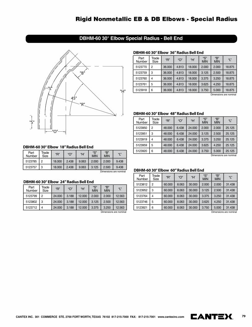
45°
"B"
"O"
"H""L"
"S"
"R"
DBHM-60 30° Elbow Special Radius - Bell End
Part Number
Trade Size “R” “O” “H’ “S”
MIN“B”MIN “L”
5123785 2 18.000 2.438 9.063 2.000 2.000 9.438
5123757 3 18.000 2.438 9.063 3.125 2.500 9.438
DBHM-60 30° Elbow 18” Radius Bell End
Part Number
Trade Size “R” “O” “H’ “S”
MIN“B”MIN “L”
5123799 2 24.000 3.188 12.000 2.000 2.000 12.563
5123802 3 24.000 3.188 12.000 3.125 2.500 12.563
5123712 4 24.000 3.188 12.000 3.375 3.250 12.563
DBHM-60 30° Elbow 24” Radius Bell End
Part Number
Trade Size “R” “O” “H’ “S”
MIN“B”MIN “L”
5123770 2 36.000 4.813 18.000 2.000 2.000 18.875
5123759 3 36.000 4.813 18.000 3.125 2.500 18.875
5123760 4 36.000 4.813 18.000 3.375 3.250 18.875
5123761 5 36.000 4.813 18.000 3.625 4.250 18.875
5123918 6 36.000 4.813 18.000 3.750 5.000 18.875
DBHM-60 30° Elbow 36” Radius Bell End
Part Number
Trade Size “R” “O” “H’ “S”
MIN“B”MIN “L”
5123950 2 48.000 6.438 24.000 2.000 2.000 25.125
5123951 3 48.000 6.438 24.000 3.125 2.500 25.125
5123919 4 48.000 6.438 24.000 3.375 3.250 25.125
5123959 5 48.000 6.438 24.000 3.625 4.250 25.125
5123920 6 48.000 6.438 24.000 3.750 5.000 25.125
DBHM-60 30° Elbow 48” Radius Bell End
Part Number
Trade Size “R” “O” “H’ “S”
MIN“B”MIN “L”
5123812 2 60.000 8.063 30.000 2.000 2.000 31.438
5123952 3 60.000 8.063 30.000 3.125 2.500 31.438
5123764 4 60.000 8.063 30.000 3.375 3.250 31.438
5123746 5 60.000 8.063 30.000 3.625 4.250 31.438
5123921 6 60.000 8.063 30.000 3.750 5.000 31.438
DBHM-60 30° Elbow 60” Radius Bell EndDimensions are nominal
Dimensions are nominal Dimensions are nominal
Dimensions are nominal
Dimensions are nominal
CANTEX INC. 301 COMMERCE STE. 2700 FORT WORTH, TEXAS 76102 817-215-7000 FAX: 817-215-7001 www.cantexinc.com 79®
Rigid Nonmetallic EB & DB Elbows - Special Radius
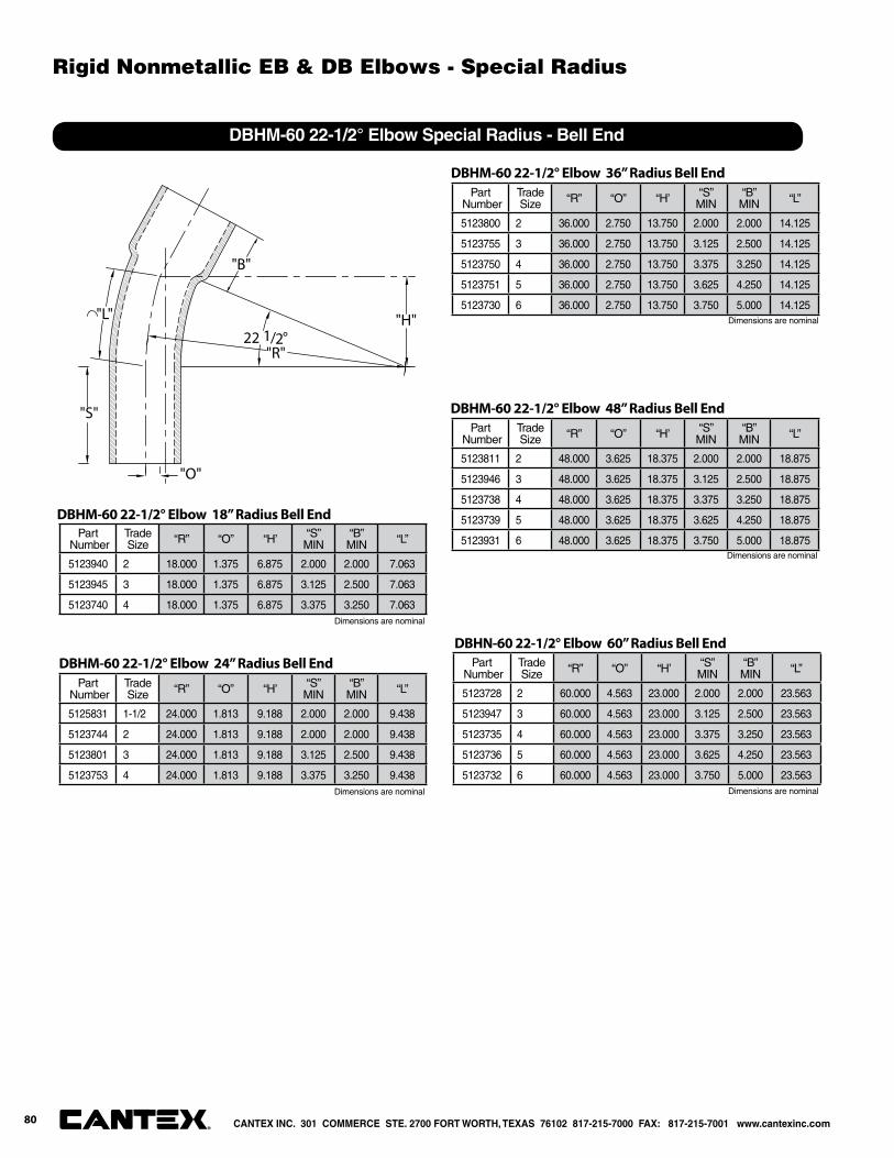
22 1/2°
"B"
"L"
"S"
"H"
"O"
"R"
DBHM-60 22-1/2° Elbow Special Radius - Bell End
Part Number
Trade Size “R” “O” “H’ “S”
MIN“B”MIN “L”
5123940 2 18.000 1.375 6.875 2.000 2.000 7.063
5123945 3 18.000 1.375 6.875 3.125 2.500 7.063
5123740 4 18.000 1.375 6.875 3.375 3.250 7.063
DBHM-60 22-1/2° Elbow 18” Radius Bell End
Part Number
Trade Size “R” “O” “H’ “S”
MIN“B”MIN “L”
5125831 1-1/2 24.000 1.813 9.188 2.000 2.000 9.438
5123744 2 24.000 1.813 9.188 2.000 2.000 9.438
5123801 3 24.000 1.813 9.188 3.125 2.500 9.438
5123753 4 24.000 1.813 9.188 3.375 3.250 9.438
DBHM-60 22-1/2° Elbow 24” Radius Bell End
Part Number
Trade Size “R” “O” “H’ “S”
MIN“B”MIN “L”
5123800 2 36.000 2.750 13.750 2.000 2.000 14.125
5123755 3 36.000 2.750 13.750 3.125 2.500 14.125
5123750 4 36.000 2.750 13.750 3.375 3.250 14.125
5123751 5 36.000 2.750 13.750 3.625 4.250 14.125
5123730 6 36.000 2.750 13.750 3.750 5.000 14.125
DBHM-60 22-1/2° Elbow 36” Radius Bell End
Part Number
Trade Size “R” “O” “H’ “S”
MIN“B”MIN “L”
5123811 2 48.000 3.625 18.375 2.000 2.000 18.875
5123946 3 48.000 3.625 18.375 3.125 2.500 18.875
5123738 4 48.000 3.625 18.375 3.375 3.250 18.875
5123739 5 48.000 3.625 18.375 3.625 4.250 18.875
5123931 6 48.000 3.625 18.375 3.750 5.000 18.875
DBHM-60 22-1/2° Elbow 48” Radius Bell End
Part Number
Trade Size “R” “O” “H’ “S”
MIN“B”MIN “L”
5123728 2 60.000 4.563 23.000 2.000 2.000 23.563
5123947 3 60.000 4.563 23.000 3.125 2.500 23.563
5123735 4 60.000 4.563 23.000 3.375 3.250 23.563
5123736 5 60.000 4.563 23.000 3.625 4.250 23.563
5123732 6 60.000 4.563 23.000 3.750 5.000 23.563
DBHN-60 22-1/2° Elbow 60” Radius Bell End
Dimensions are nominal
Dimensions are nominal
Dimensions are nominal Dimensions are nominal
Dimensions are nominal
CANTEX INC. 301 COMMERCE STE. 2700 FORT WORTH, TEXAS 76102 817-215-7000 FAX: 817-215-7001 www.cantexinc.com®
80
Rigid Nonmetallic EB & DB Elbows - Special Radius
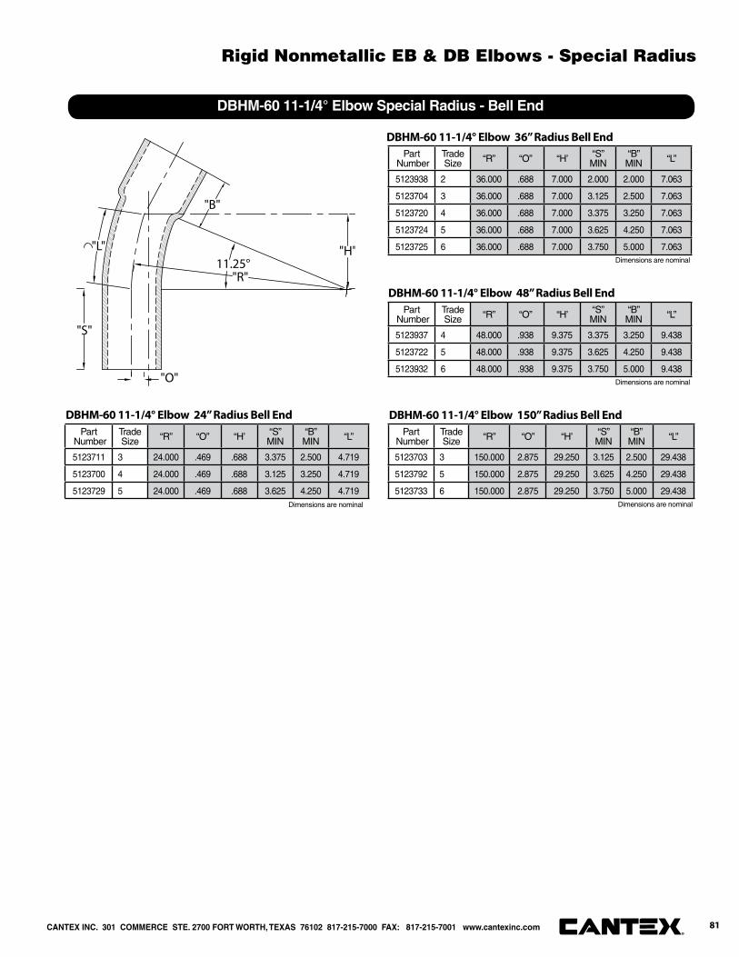
11.25°
"B"
"L"
"S"
"H"
"O"
"R"
DBHM-60 11-1/4° Elbow Special Radius - Bell End
Part Number
Trade Size “R” “O” “H’ “S”
MIN“B”MIN “L”
5123711 3 24.000 .469 .688 3.375 2.500 4.719
5123700 4 24.000 .469 .688 3.125 3.250 4.719
5123729 5 24.000 .469 .688 3.625 4.250 4.719
DBHM-60 11-1/4° Elbow 24” Radius Bell End
Part Number
Trade Size “R” “O” “H’ “S”
MIN“B”MIN “L”
5123938 2 36.000 .688 7.000 2.000 2.000 7.063
5123704 3 36.000 .688 7.000 3.125 2.500 7.063
5123720 4 36.000 .688 7.000 3.375 3.250 7.063
5123724 5 36.000 .688 7.000 3.625 4.250 7.063
5123725 6 36.000 .688 7.000 3.750 5.000 7.063
DBHM-60 11-1/4° Elbow 36” Radius Bell End
Part Number
Trade Size “R” “O” “H’ “S”
MIN“B”MIN “L”
5123937 4 48.000 .938 9.375 3.375 3.250 9.438
5123722 5 48.000 .938 9.375 3.625 4.250 9.438
5123932 6 48.000 .938 9.375 3.750 5.000 9.438
DBHM-60 11-1/4° Elbow 48” Radius Bell End
Part Number
Trade Size “R” “O” “H’ “S”
MIN“B”MIN “L”
5123703 3 150.000 2.875 29.250 3.125 2.500 29.438
5123792 5 150.000 2.875 29.250 3.625 4.250 29.438
5123733 6 150.000 2.875 29.250 3.750 5.000 29.438
DBHM-60 11-1/4° Elbow 150” Radius Bell End
Dimensions are nominal Dimensions are nominal
Dimensions are nominal
Dimensions are nominal
CANTEX INC. 301 COMMERCE STE. 2700 FORT WORTH, TEXAS 76102 817-215-7000 FAX: 817-215-7001 www.cantexinc.com 81®
Rigid Nonmetallic EB & DB Elbows - Special Radius

90°
"O"
"B"
"R"
"S"
"H"
DBHM-120 90° Elbow for Type EB & DB Duct Special Radius - Bell End
Part Number
Trade Size “R” “O” “H’ “S”
MIN“B”MIN “L”
5123861 1-1/2 18.000 18.000 18.000 2.000 2.000 28.250
5125862 2 18.000 18.000 18.000 2.000 2.000 28.250
5125870 3 18.000 18.000 18.000 3.125 2.500 28.250
5125874 4 18.000 18.000 18.000 3.375 3.250 28.250
DBHM-120 90° Elbow 18” Radius Bell End
Part Number
Trade Size “R” “O” “H’ “S”
MIN“B”MIN “L”
5125742 1-1/2 24.000 24.000 24.000 2.000 2.000 37.688
5125881 2 24.000 24.000 24.000 2.000 2.000 37.688
5125871 3 24.000 24.000 24.000 3.125 2.500 37.688
5125875 4 24.000 24.000 24.000 3.375 3.250 37.688
5125898 5 24.000 24.000 24.000 3.625 4.250 37.688
DBHM-120 90° Elbow 24” Radius Bell End
Part Number
Trade Size “R” “O” “H’ “S”
MIN“B”MIN “L”
5123862 1-1/2 36.000 36.000 36.000 2.000 2.000 56.500
5125869 2 36.000 36.000 36.000 2.000 2.000 56.500
5125872 3 36.000 36.000 36.000 3.125 2.500 56.500
5125876 4 36.000 36.000 36.000 3.375 3.250 56.500
5125880 5 36.000 36.000 36.000 3.625 4.250 56.500
5125884 6 36.000 36.000 36.000 3.750 5.000 56.500
DBHM-120 90° Elbow 36” Radius Bell End
Part Number
Trade Size “R” “O” “H’ “S”
MIN“B”MIN “L”
5123863 1-1/2 48.000 48.000 48.000 2.000 2.000 75.375
5125740 2 48.000 48.000 48.000 2.000 2.000 75.375
5125741 3 48.000 48.000 48.000 3.125 2.500 75.375
5125877 4 48.000 48.000 48.000 3.375 3.250 75.375
5125901 5 48.000 48.000 48.000 3.625 4.250 75.375
5125885 6 48.000 48.000 48.000 3.750 5.000 75.375
DBHM-120 90° Elbow 48” Radius Bell End
Part Number
Trade Size “R” “O” “H’ “S”
MIN“B”MIN “L”
5125859 2 60.000 60.000 60.000 2.000 2.000 94.250
5125873 3 60.000 60.000 60.000 3.125 2.500 94.250
5125878 4 60.000 60.000 60.000 3.375 3.250 94.250
5125899 5 60.000 60.000 60.000 3.625 4.250 94.250
5125895 6 60.000 60.000 60.000 3.750 5.000 94.250
DBHM-120 90° Elbow 60” Radius Bell End
Dimensions are nominal
Dimensions are nominal Dimensions are nominal
Dimensions are nominal
Dimensions are nominal
CANTEX INC. 301 COMMERCE STE. 2700 FORT WORTH, TEXAS 76102 817-215-7000 FAX: 817-215-7001 www.cantexinc.com®
82
Rigid Nonmetallic EB & DB Elbows - Special Radius

45°
"B"
"O"
"H""L"
"S"
"R"
DBHM-120 45° Elbow Special Radius - Bell End
Part Number
Trade Size “R” “O” “H’ “S”
MIN“B”MIN “L”
5125746 2 18.000 2.438 9.063 2.000 2.000 9.438
5125747 3 18.000 2.438 9.063 3.125 2.500 9.438
DBHM-120 45° Elbow 18” Radius Bell End
Part Number
Trade Size “R” “O” “H’ “S”
MIN“B”MIN “L”
5125815 1-1/2 24.000 3.188 12.000 2.000 2.000 12.563
5125767 2 24.000 3.188 12.000 2.000 2.000 12.563
5125774 3 24.000 3.188 12.000 3.125 2.500 12.563
5125753 4 24.000 3.188 12.000 3.375 3.250 12.563
DBHM-120 45° Elbow 24” Radius Bell End
Part Number
Trade Size “R” “O” “H’ “S”
MIN“B”MIN “L”
5125736 1-1/2 36.000 4.813 18.000 2.000 2.000 18.875
5125879 2 36.000 4.813 18.000 2.000 2.000 18.875
5125772 3 36.000 4.813 18.000 3.125 2.500 18.875
5125776 4 36.000 4.813 18.000 3.375 3.250 18.875
5125781 5 36.000 4.813 18.000 3.625 4.250 18.875
5125784 6 36.000 4.813 18.000 3.750 5.000 18.875
DBHM-120 45° Elbow 36” Radius Bell End
Part Number
Trade Size “R” “O” “H’ “S”
MIN“B”MIN “L”
5125769 2 48.000 6.438 24.000 2.000 2.000 25.125
5125737 3 48.000 6.438 24.000 3.125 2.500 25.125
5125744 4 48.000 6.438 24.000 3.375 3.250 25.125
5125783 5 48.000 6.438 24.000 3.625 4.250 25.125
5125796 6 48.000 6.438 24.000 3.750 5.000 25.125
DBHM-120 45° Elbow 48” Radius Bell End
Part Number
Trade Size “R” “O” “H’ “S”
MIN“B”MIN “L”
5125748 3 60.000 8.063 30.000 3.125 2.500 31.438
5125738 4 60.000 8.063 30.000 3.375 3.250 31.438
5125782 5 60.000 8.063 30.000 3.625 4.250 31.438
5125795 6 60.000 8.063 30.000 3.750 5.000 31.438
DBHM-120 45° Elbow 60” Radius Bell End
Dimensions are nominal
Dimensions are nominal
Dimensions are nominal Dimensions are nominal
Dimensions are nominal
CANTEX INC. 301 COMMERCE STE. 2700 FORT WORTH, TEXAS 76102 817-215-7000 FAX: 817-215-7001 www.cantexinc.com 83®
Rigid Nonmetallic EB & DB Elbows - Special Radius
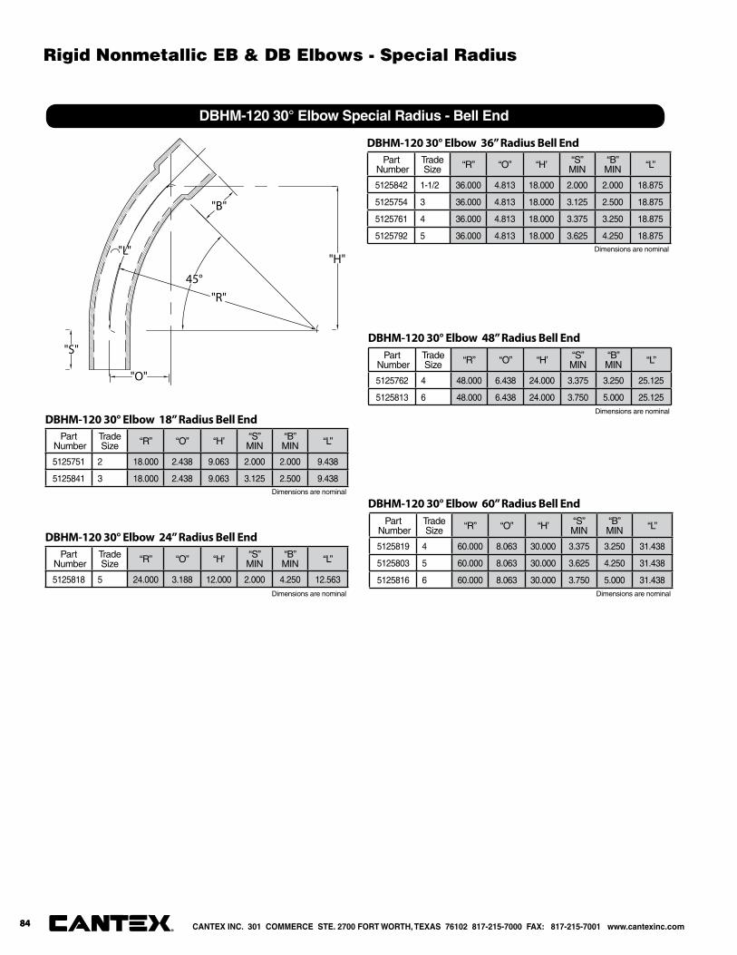
45°
"B"
"O"
"H""L"
"S"
"R"
DBHM-120 30° Elbow Special Radius - Bell End
Part Number
Trade Size “R” “O” “H’ “S”
MIN“B”MIN “L”
5125751 2 18.000 2.438 9.063 2.000 2.000 9.438
5125841 3 18.000 2.438 9.063 3.125 2.500 9.438
DBHM-120 30° Elbow 18” Radius Bell End
Part Number
Trade Size “R” “O” “H’ “S”
MIN“B”MIN “L”
5125818 5 24.000 3.188 12.000 2.000 4.250 12.563
DBHM-120 30° Elbow 24” Radius Bell End
Part Number
Trade Size “R” “O” “H’ “S”
MIN“B”MIN “L”
5125842 1-1/2 36.000 4.813 18.000 2.000 2.000 18.875
5125754 3 36.000 4.813 18.000 3.125 2.500 18.875
5125761 4 36.000 4.813 18.000 3.375 3.250 18.875
5125792 5 36.000 4.813 18.000 3.625 4.250 18.875
DBHM-120 30° Elbow 36” Radius Bell End
Part Number
Trade Size “R” “O” “H’ “S”
MIN“B”MIN “L”
5125762 4 48.000 6.438 24.000 3.375 3.250 25.125
5125813 6 48.000 6.438 24.000 3.750 5.000 25.125
DBHM-120 30° Elbow 48” Radius Bell End
Part Number
Trade Size “R” “O” “H’ “S”
MIN“B”MIN “L”
5125819 4 60.000 8.063 30.000 3.375 3.250 31.438
5125803 5 60.000 8.063 30.000 3.625 4.250 31.438
5125816 6 60.000 8.063 30.000 3.750 5.000 31.438
DBHM-120 30° Elbow 60” Radius Bell End
Dimensions are nominal
Dimensions are nominal
Dimensions are nominal
Dimensions are nominal
Dimensions are nominal
CANTEX INC. 301 COMMERCE STE. 2700 FORT WORTH, TEXAS 76102 817-215-7000 FAX: 817-215-7001 www.cantexinc.com®
84
Rigid Nonmetallic EB & DB Elbows - Special Radius
84
Service Entrance Caps, Meter Offsets, Risers and Spacers

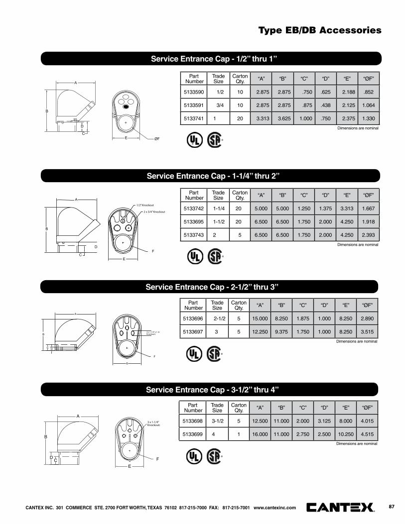
Part Number
Trade Size
Carton Qty. “A” “B” “C” “D” “E” “ØF”
5133590 1/2 10 2.875 2.875 .750 .625 2.188 .852
5133591 3/4 10 2.875 2.875 .875 .438 2.125 1.064
5133741 1 20 3.313 3.625 1.000 .750 2.375 1.330
Service Entrance Cap - 1/2” thru 1”
A
B
D
CE ØF
Part Number
Trade Size
Carton Qty. “A” “B” “C” “D” “E” “ØF”
5133742 1-1/4 20 5.000 5.000 1.250 1.375 3.313 1.667
5133695 1-1/2 20 6.500 6.500 1.750 2.000 4.250 1.918
5133743 2 5 6.500 6.500 1.750 2.000 4.250 2.393
Service Entrance Cap - 1-1/4” thru 2”
A
B
D
CE
�F
1/2” Knockout
2 x 3/4” Knockout
Part Number
Trade Size
Carton Qty. “A” “B” “C” “D” “E” “ØF”
5133696 2-1/2 5 15.000 8.250 1.875 1.000 8.250 2.890
5133697 3 5 12.250 9.375 1.750 1.000 8.250 3.515
Service Entrance Cap - 2-1/2” thru 3”
A
B
E
�F
C D
3 x 1-1/4” x 1-3/4Knockouts
Part Number
Trade Size
Carton Qty. “A” “B” “C” “D” “E” “ØF”
5133698 3-1/2 5 12.500 11.000 2.000 3.125 8.000 4.015
5133699 4 1 16.000 11.000 2.750 2.500 10.250 4.515
Service Entrance Cap - 3-1/2” thru 4”
A
B
E�FCD
3 x 1-1/4”Knockouts
Dimensions are nominal
Dimensions are nominal
Dimensions are nominal
Dimensions are nominal
CANTEX INC. 301 COMMERCE STE. 2700 FORT WORTH, TEXAS 76102 817-215-7000 FAX: 817-215-7001 www.cantexinc.com 87®
Type EB/DB Accessories
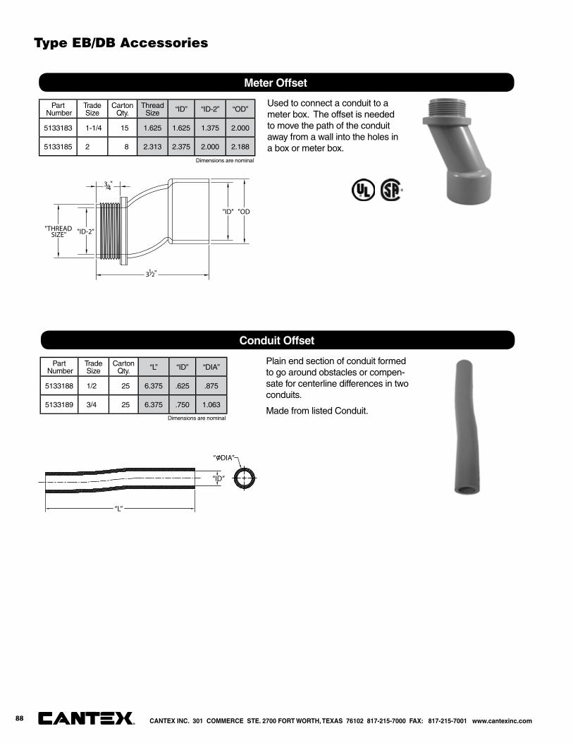
Part Number
Trade Size
Carton Qty.
ThreadSize “ID” “ID-2” “OD”
5133183 1-1/4 15 1.625 1.625 1.375 2.000
5133185 2 8 2.313 2.375 2.000 2.188
Meter Offset
"OD""ID"
3 12"
"ID-2""THREADSIZE"
34"
Part Number
Trade Size
Carton Qty. “L” “ID” “DIA”
5133188 1/2 25 6.375 .625 .875
5133189 3/4 25 6.375 .750 1.063
Conduit Offset
“L”
“ DIA”
“ID”
Used to connect a conduit to a meter box. The offset is needed to move the path of the conduit away from a wall into the holes in a box or meter box.
Plain end section of conduit formed to go around obstacles or compen-sate for centerline differences in two conduits.
Made from listed Conduit.
Dimensions are nominal
Dimensions are nominal
CANTEX INC. 301 COMMERCE STE. 2700 FORT WORTH, TEXAS 76102 817-215-7000 FAX: 817-215-7001 www.cantexinc.com®
Type EB/DB Accessories
88
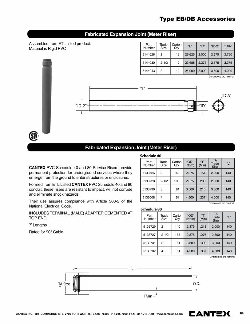
Part Number
Trade Size
Carton Qty. “L” “ID” “ID-2” “DIA”
5144028 2 16 26.625 2.000 2.375 2.750
5144030 2-1/2 12 23.688 2.375 2.875 3.375
5144043 3 12 24.000 3.000 3.500 4.000
Fabricated Expansion Joint (Meter Riser)
“ID-2”
“L”
“ID”
“DIA”
Assembled from ETL listed product.Material is Rigid PVC
Part Number
Trade Size
Carton Qty.
“OD”(Nom)
“T”(Min)
TA Trade Size
“L”
5133726 2 140 2.375 .154 2.000 140
5133728 2-1/2 135 2.875 .203 2.500 140
5133730 3 81 3.500 .216 3.000 140
5136008 4 51 4.500 .237 4.000 140
Fabricated Expansion Joint (Meter Riser)
L
TMin
TA Size O.D.
CANTEX PVC Schedule 40 and 80 Service Risers provide permanent protection for underground services where they emerge from the ground to enter structures or enclosures.
Formed from ETL Listed CANTEX PVC Schedule 40 and 80 conduit, these risers are resistant to impact, will not corrode and eliminate shock hazards.
Their use assures compliance with Article 300-5 of the National Electrical Code.
INCLUDES TERMINAL (MALE) ADAPTER CEMENTED AT TOP END.
7’ Lengths
Rated for 90° Cable
Schedule 40
Part Number
Trade Size
Carton Qty.
“OD”(Nom)
“T”(Min)
TA Trade Size
“L”
5133729 2 140 2.375 .218 2.000 140
5133727 2-1/2 135 2.875 .276 2.500 140
5133731 3 81 3.500 .300 3.000 140
5133732 4 51 4.500 .337 4.000 140
Schedule 80
Dimensions are nominal
Dimensions are nominal
Dimensions are nominal
CANTEX INC. 301 COMMERCE STE. 2700 FORT WORTH, TEXAS 76102 817-215-7000 FAX: 817-215-7001 www.cantexinc.com 89®
Type EB/DB Accessories
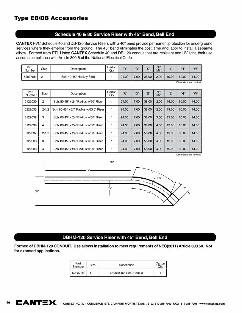
Part Number Size Description Carton
Qty. “R” “O” “S” “B”Min. “L” “H” “W”
5283768 2 Sch. 40 45° Hockey Stick 1 24.00 7.00 38.00 2.00 19.00 60.00 14.00
DBHM-120 Service Riser with 45° Bend, Bell End
CANTEX PVC Schedule 40 and DB-120 Service Risers with a 40° bend provide permanent protection for underground services where they emerge from the ground. The 45° bend eliminates the cost, time and labor to install a separate elbow. Formed from ETL Listed CANTEX Schedule 40 and DB-120 conduit that are resistant and UV light, their use assures compliance with Article 300-5 of the National Electrical Code.
Part Number Size Description Carton
Qty. “R” “O” “S” “B”Min. “L” “H” “W”
5122030 2 Sch. 80 45° x 24” Radius w/60” Riser 1 24.00 7.00 38.00 2.00 19.00 60.00 14.00
5222035 2-1/2 Sch. 80 45° x 24” Radius w/63.5” Riser 1 24.00 7.00 38.00 2.50 19.00 60.00 14.00
5122032 3 Sch. 80 45° x 24” Radius w/60” Riser 1 24.00 7.00 38.00 3.00 19.00 60.00 14.00
5122039 4 Sch. 80 45° x 24” Radius w/60” Riser 1 24.00 7.00 38.00 4.00 19.00 60.00 14.00
5122037 2-1/2 Sch. 80 45° x 24” Radius w/80” Riser 1 24.00 7.00 58.00 4.00 19.00 80.00 14.00
5122033 3 Sch. 80 45° x 24” Radius w/80” Riser 1 24.00 7.00 58.00 4.00 19.00 80.00 14.00
5122038 4 Sch. 80 45° x 24” Radius w/80” Riser 1 24.00 7.00 58.00 4.00 19.00 80.00 14.00
Schedule 40 & 80 Service Riser with 45° Bend, Bell End
"H"
"W"
"S"
"B"
R24
"L"
45°"O"
Dimensions are nominal
Dimensions are nominal
Part Number Size Description Carton
Qty.
5283766 1 DB120 45° x 24” Radius 1
Formed of DBHM-120 CONDUIT. Use allows installation to meet requirements of NEC(2011) Article 300.50. Not for exposed applications.
CANTEX INC. 301 COMMERCE STE. 2700 FORT WORTH, TEXAS 76102 817-215-7000 FAX: 817-215-7001 www.cantexinc.com®
90
Type EB/DB Accessories
90
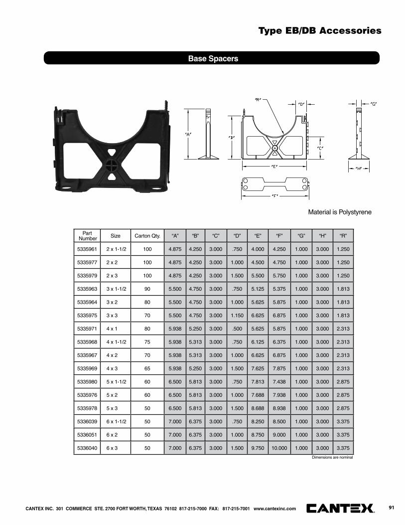
Part Number Size Carton Qty. “A” “B” “C” “D” “E” “F” “G” “H” “R”
5335961 2 x 1-1/2 100 4.875 4.250 3.000 .750 4.000 4.250 1.000 3.000 1.250
5335977 2 x 2 100 4.875 4.250 3.000 1.000 4.500 4.750 1.000 3.000 1.250
5335979 2 x 3 100 4.875 4.250 3.000 1.500 5.500 5.750 1.000 3.000 1.250
5335963 3 x 1-1/2 90 5.500 4.750 3.000 .750 5.125 5.375 1.000 3.000 1.813
5335964 3 x 2 80 5.500 4.750 3.000 1.000 5.625 5.875 1.000 3.000 1.813
5335975 3 x 3 70 5.500 4.750 3.000 1.150 6.625 6.875 1.000 3.000 1.813
5335971 4 x 1 80 5.938 5.250 3.000 .500 5.625 5.875 1.000 3.000 2.313
5335968 4 x 1-1/2 75 5.938 5.313 3.000 .750 6.125 6.375 1.000 3.000 2.313
5335967 4 x 2 70 5.938 5.313 3.000 1.000 6.625 6.875 1.000 3.000 2.313
5335969 4 x 3 65 5.938 5.250 3.000 1.500 7.625 7.875 1.000 3.000 2.313
5335980 5 x 1-1/2 60 6.500 5.813 3.000 .750 7.813 7.438 1.000 3.000 2.875
5335976 5 x 2 60 6.500 5.813 3.000 1.000 7.688 7.938 1.000 3.000 2.875
5335978 5 x 3 50 6.500 5.813 3.000 1.500 8.688 8.938 1.000 3.000 2.875
5336039 6 x 1-1/2 50 7.000 6.375 3.000 .750 8.250 8.500 1.000 3.000 3.375
5336051 6 x 2 50 7.000 6.375 3.000 1.000 8.750 9.000 1.000 3.000 3.375
5336040 6 x 3 50 7.000 6.375 3.000 1.500 9.750 10.000 1.000 3.000 3.375
Base Spacers
Material is Polystyrene
Dimensions are nominal
CANTEX INC. 301 COMMERCE STE. 2700 FORT WORTH, TEXAS 76102 817-215-7000 FAX: 817-215-7001 www.cantexinc.com 91®
Type EB/DB Accessories
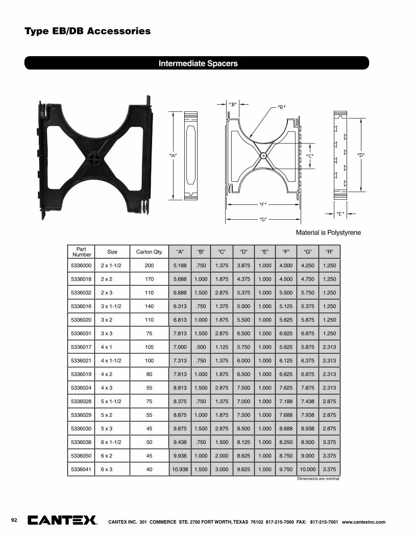
Part Number Size Carton Qty. “A” “B” “C” “D” “E” “F” “G” “R”
5336000 2 x 1-1/2 200 5.188 .750 1.375 3.875 1.000 4.000 4.250 1.250
5336018 2 x 2 170 5.688 1.000 1.875 4.375 1.000 4.500 4.750 1.250
5336032 2 x 3 110 6.688 1.500 2.875 5.375 1.000 5.500 5.750 1.250
5336016 3 x 1-1/2 140 6.313 .750 1.375 5.000 1.000 5.125 5.375 1.250
5336020 3 x 2 110 6.813 1.000 1.875 5.500 1.000 5.625 5.875 1.250
5336031 3 x 3 75 7.813 1.500 2.875 6.500 1.000 6.625 6.875 1.250
5336017 4 x 1 105 7.000 .500 1.125 5.750 1.000 5.625 5.875 2.313
5336021 4 x 1-1/2 100 7.313 .750 1.375 6.000 1.000 6.125 6.375 2.313
5336019 4 x 2 80 7.813 1.000 1.875 6.500 1.000 6.625 6.875 2.313
5336024 4 x 3 55 8.813 1.500 2.875 7.500 1.000 7.625 7.875 2.313
5336028 5 x 1-1/2 75 8.375 .750 1.375 7.000 1.000 7.188 7.438 2.875
5336029 5 x 2 55 8.875 1.000 1.875 7.500 1.000 7.688 7.938 2.875
5336030 5 x 3 45 9.875 1.500 2.875 8.500 1.000 8.688 8.938 2.875
5336038 6 x 1-1/2 50 9.438 .750 1.500 8.125 1.000 8.250 8.500 3.375
5336050 6 x 2 45 9.938 1.000 2.000 8.625 1.000 8.750 9.000 3.375
5336041 6 x 3 40 10.938 1.500 3.000 9.625 1.000 9.750 10.000 3.375
Intermediate Spacers
Material is Polystyrene
Dimensions are nominal
CANTEX INC. 301 COMMERCE STE. 2700 FORT WORTH, TEXAS 76102 817-215-7000 FAX: 817-215-7001 www.cantexinc.com®
92
Type EB/DB Accessories
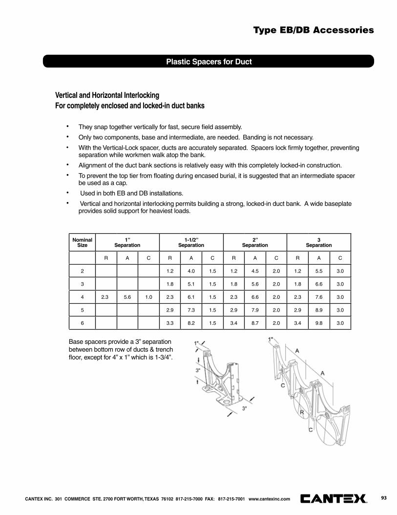
Plastic Spacers for Duct
Vertical and Horizontal InterlockingFor completely enclosed and locked-in duct banks
· They snap together vertically for fast, secure fi eld assembly.
· Only two components, base and intermediate, are needed. Banding is not necessary.
· With the Vertical-Lock spacer, ducts are accurately separated. Spacers lock fi rmly together, preventing separation while workmen walk atop the bank.
· Alignment of the duct bank sections is relatively easy with this completely locked-in construction.
· To prevent the top tier from fl oating during encased burial, it is suggested that an intermediate spacer be used as a cap.
· Used in both EB and DB installations.
· Vertical and horizontal interlocking permits building a strong, locked-in duct bank. A wide baseplate provides solid support for heaviest loads.
NominalSize
1”Separation
1-1/2”Separation
2”Separation
3Separation
R A C R A C R A C R A C
2 1.2 4.0 1.5 1.2 4.5 2.0 1.2 5.5 3.0
3 1.8 5.1 1.5 1.8 5.6 2.0 1.8 6.6 3.0
4 2.3 5.6 1.0 2.3 6.1 1.5 2.3 6.6 2.0 2.3 7.6 3.0
5 2.9 7.3 1.5 2.9 7.9 2.0 2.9 8.9 3.0
6 3.3 8.2 1.5 3.4 8.7 2.0 3.4 9.8 3.0
Base spacers provide a 3” separation between bottom row of ducts & trench fl oor, except for 4” x 1” which is 1-3/4”.
CANTEX INC. 301 COMMERCE STE. 2700 FORT WORTH, TEXAS 76102 817-215-7000 FAX: 817-215-7001 www.cantexinc.com 93®
Type EB/DB Accessories


Conduit, Utility Duct and P&C Flexible Duct

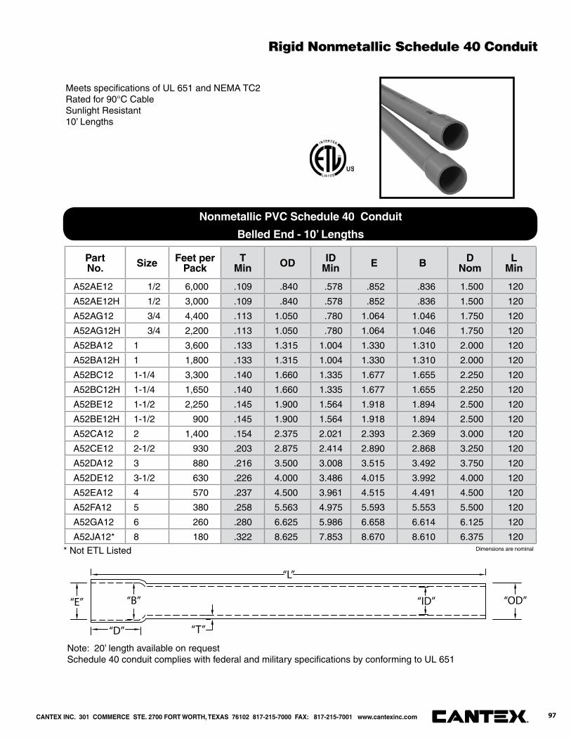
Meets specifi cations of UL 651 and NEMA TC2Rated for 90°C CableSunlight Resistant10’ Lengths
Part No. Size Feet per
PackT
Min OD IDMin E B D
NomL
Min
A52AE12 1/2 6,000 .109 .840 .578 .852 .836 1.500 120
A52AE12H 1/2 3,000 .109 .840 .578 .852 .836 1.500 120
A52AG12 3/4 4,400 .113 1.050 .780 1.064 1.046 1.750 120
A52AG12H 3/4 2,200 .113 1.050 .780 1.064 1.046 1.750 120
A52BA12 1 3,600 .133 1.315 1.004 1.330 1.310 2.000 120
A52BA12H 1 1,800 .133 1.315 1.004 1.330 1.310 2.000 120
A52BC12 1-1/4 3,300 .140 1.660 1.335 1.677 1.655 2.250 120
A52BC12H 1-1/4 1,650 .140 1.660 1.335 1.677 1.655 2.250 120
A52BE12 1-1/2 2,250 .145 1.900 1.564 1.918 1.894 2.500 120
A52BE12H 1-1/2 900 .145 1.900 1.564 1.918 1.894 2.500 120
A52CA12 2 1,400 .154 2.375 2.021 2.393 2.369 3.000 120
A52CE12 2-1/2 930 .203 2.875 2.414 2.890 2.868 3.250 120
A52DA12 3 880 .216 3.500 3.008 3.515 3.492 3.750 120
A52DE12 3-1/2 630 .226 4.000 3.486 4.015 3.992 4.000 120
A52EA12 4 570 .237 4.500 3.961 4.515 4.491 4.500 120
A52FA12 5 380 .258 5.563 4.975 5.593 5.553 5.500 120
A52GA12 6 260 .280 6.625 5.986 6.658 6.614 6.125 120
A52JA12* 8 180 .322 8.625 7.853 8.670 8.610 6.375 120
* Not ETL Listed
Note: 20’ length available on requestSchedule 40 conduit complies with federal and military specifi cations by conforming to UL 651
“E”
“D”
“B”
“T”
“L”
“ID” “OD”
Nonmetallic PVC Schedule 40 Conduit
Belled End - 10’ Lengths
Dimensions are nominal
Rigid Nonmetallic Schedule 40 Conduit
CANTEX INC. 301 COMMERCE STE. 2700 FORT WORTH, TEXAS 76102 817-215-7000 FAX: 817-215-7001 www.cantexinc.com 97®

Meets specifi cations of UL 651 and NEMA TC2Rated for 90°C CableSunlight Resistant10’ Lengths
Part No. Size Feet per
PackT
Min OD IDMin E B D
NomL
Min
A53AE12 1/2 6,000 .147 .840 .502 .852 .836 1.500 120
A53AE12H 1/2 3,000 .147 .840 .502 .852 .836 1.500 120
A53AG12 3/4 4,400 .154 1.050 .698 1.064 1.046 1.750 120
A53AG12H 3/4 2,200 .154 1.050 .698 1.064 1.046 1.750 120
A53BA12 1 3,600 .179 1.315 .910 1.330 1.310 2.000 120
A53BA12H 1 1,800 .179 1.315 .910 1.330 1.310 2.000 120
A53BC12 1-1/4 3,300 .191 1.660 1.227 1.677 1.655 2.250 120
A53BC12H 1-1/4 1,650 .191 1.660 1.227 1.677 1.655 2.250 120
A53BE12 1-1/2 2,250 .200 1.900 1.446 1.918 1.894 2.500 120
A53BE12H 1-1/2 900 .200 1.900 1.446 1.918 1.894 2.500 120
A53CA12 2 1,400 .218 2.375 1.881 2.393 2.369 3.000 120
A53CE12 2-1/2 930 .276 2.875 2.250 2.890 2.868 3.250 120
A53DA12 3 880 .300 3.500 2.820 3.515 3.492 3.750 120
A53EA12 4 570 .337 4.500 3.737 4.515 4.491 4.500 120
A53FA12 5 380 .375 5.563 4.713 5.593 5.553 5.500 120
A53GA12 6 260 .432 6.625 5.646 6.658 6.614 6.125 120
Note: 20’ length available on requestSchedule 80 conduit complies with federal and military specifi cations by conforming to UL 651
“E”
“D”
“B”
“T”
“L”
“ID” “OD”
Nonmetallic PVC Schedule 80 Conduit
Belled End - 10’ Lengths
Dimensions are nominal
Rigid Nonmetallic Schedule 80 Conduit
CANTEX INC. 301 COMMERCE STE. 2700 FORT WORTH, TEXAS 76102 817-215-7000 FAX: 817-215-7001 www.cantexinc.com®
98
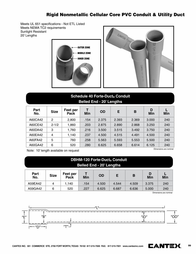
Meets UL 651 specifi cations - Not ETL ListedMeets NEMA TC2 requirementsSunlight Resistant20’ Lengths
Note: 10’ length available on request
Part No. Size Feet per
PackT
Min OD E B DMin
LMin
A60CA42 2 2,800 .154 2.375 2.393 2.369 3.000 240
A60CE42 2-1/2 1,860 .203 2.875 2.890 2.868 3.250 240
A60DA42 3 1,760 .216 3.500 3.515 3.492 3.750 240
A60EA42 4 1,140 .237 4.500 4.515 4.491 4.500 240
A60FA42 5 760 .258 5.563 5.593 5.553 5.500 240
A60GA42 6 520 .280 6.625 6.658 6.614 6.125 240
Part No. Size Feet per
PackT
Min OD E B DMin
LMin
A59EA42 4 1,140 .154 4.500 4.544 4.509 3.375 240
A59GA42 6 520 .227 6.625 6.687 6.636 5.000 240
“E”
“D”
“B”
“T”
“L”
“ID” “OD”
Schedule 40 Forte-Duct® ConduitBelled End - 20’ Lengths
DBHM-120 Forte-Duct® ConduitBelled End - 20’ Lengths
Dimensions are nominal
Dimensions are nominal
CANTEX INC. 301 COMMERCE STE. 2700 FORT WORTH, TEXAS 76102 817-215-7000 FAX: 817-215-7001 www.cantexinc.com 99®
Rigid Nonmetallic Cellular Core PVC Conduit & Utility Duct
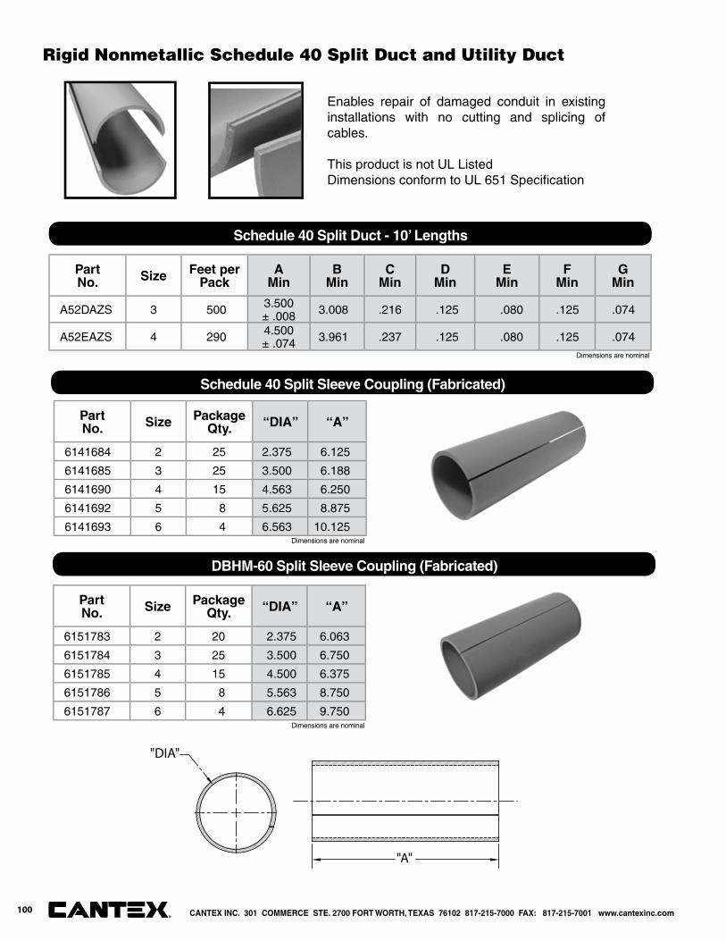
Enables repair of damaged conduit in existing installations with no cutting and splicing of cables.
This product is not UL ListedDimensions conform to UL 651 Specifi cation
Part No. Size Feet per
PackA
MinB
MinC
MinD
MinE
MinF
MinG
Min
A52DAZS 3 500 3.500± .008 3.008 .216 .125 .080 .125 .074
A52EAZS 4 290 4.500± .074 3.961 .237 .125 .080 .125 .074
Schedule 40 Split Duct - 10’ Lengths
Part No. Size Package
Qty. “DIA” “A”
6141684 2 25 2.375 6.125
6141685 3 25 3.500 6.188
6141690 4 15 4.563 6.250
6141692 5 8 5.625 8.875
6141693 6 4 6.563 10.125
"DIA"
"A"
Part No. Size Package
Qty. “DIA” “A”
6151783 2 20 2.375 6.063
6151784 3 25 3.500 6.750
6151785 4 15 4.500 6.375
6151786 5 8 5.563 8.750
6151787 6 4 6.625 9.750
Schedule 40 Split Sleeve Coupling (Fabricated)
DBHM-60 Split Sleeve Coupling (Fabricated)
Dimensions are nominal
Dimensions are nominal
Dimensions are nominal
CANTEX INC. 301 COMMERCE STE. 2700 FORT WORTH, TEXAS 76102 817-215-7000 FAX: 817-215-7001 www.cantexinc.com®
100
Rigid Nonmetallic Schedule 40 Split Duct and Utility Duct

Conforms to NEMA TC6 and ASTM F-512 requirementsRated for 90°C Cable20’ Lengths
Part No. Size Feet per
Pack“T”Min “OD” “E” “B” “D”
Min.“L”
Min.
A79CA42 2 2,800 .060 2.375 2.400 2.381 1.750 240
A79DA42 3 1,760 .092 3.500 3.538 3.508 2.875 240
A79EA42 4 1,140 .121 4.500 4.544 4.509 3.375 240
A79FA42 5 760 .152 5.563 5.614 5.573 4.000 240
A79GA42 6 520 .182 6.625 6.687 6.636 5.00 240
Part No. Size Feet per
Pack“T”Min “OD” “E” “B” “D”
Min.“L”
Min.
A77CA42 2 2,800 .060 2.387 2.396 2.378 1.750 240
A77DA42 3 1,760 .061 3.500 3.529 3.503 2.875 240
A77EA42 4 1,140 .082 4.500 4.533 4.502 3.375 240
A77FA42 5 760 .103 5.563 5.601 5.562 4.000 240
A77GA42 6 520 .125 6.625 6.669 6.627 5.000 240
“E”
“D”
“B”
“T”
“L”
“ID” “OD”
Type EB complies with federal and military specifi cations by conforming to UL 651
Part No. Size Feet per
Pack“T”Min “OD” “E” “B” “D”
Min.“L”
Min.
A72DA42 3 1,760 .112 3.500 3.538 3.508 2.875 240
A72EA42 4 1,140 .145 4.500 4.544 4.509 3.375 240
A72FA42 5 760 .179 5.563 5.614 5.573 4.000 240
A72GA42 6 520 .213 6.625 6.687 6.636 5.000 240
Type DBHM-60 (For Direct Burial) - 20’ Lengths, Bell End
Type EBHM-20 (For Encasement Burial) - 20’ Lengths, Bell End
Type DBHM-100 (For Direct Burial) - 20’ Lengths, Bell End
Dimensions are nominal
Dimensions are nominal
Dimensions are nominal
Rigid Nonmetallic PVC Utility Duct 500,000 PSI Modulus
CANTEX INC. 301 COMMERCE STE. 2700 FORT WORTH, TEXAS 76102 817-215-7000 FAX: 817-215-7001 www.cantexinc.com 101®
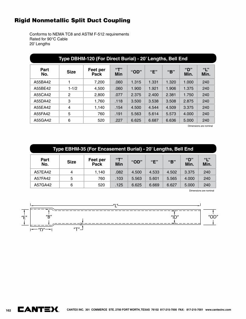
Dimensions are nominal
Conforms to NEMA TC8 and ASTM F-512 requirementsRated for 90°C Cable20’ Lengths
“E”
“D”
“B”
“T”
“L”
“ID” “OD”
Part No. Size Feet per
Pack“T”Min “OD” “E” “B” “D”
Min.“L”
Min.
A55BA42 1 7,200 .060 1.315 1.331 1.320 1.000 240
A55BE42 1-1/2 4,500 .060 1.900 1.921 1.906 1.375 240
A55CA42 2 2,800 .077 2.375 2.400 2.381 1.750 240
A55DA42 3 1,760 .118 3.500 3.538 3.508 2.875 240
A55EA42 4 1,140 .154 4.500 4.544 4.509 3.375 240
A55FA42 5 760 .191 5.563 5.614 5.573 4.000 240
A55GA42 6 520 .227 6.625 6.687 6.636 5.000 240
Part No. Size Feet per
Pack“T”Min “OD” “E” “B” “D”
Min.“L”
Min.
A57EA42 4 1,140 .082 4.500 4.533 4.502 3.375 240
A57FA42 5 760 .103 5.563 5.601 5.565 4.000 240
A57GA42 6 520 .125 6.625 6.669 6.627 5.000 240
Type DBHM-120 (For Direct Burial) - 20’ Lengths, Bell End
Type EBHM-35 (For Encasement Burial) - 20’ Lengths, Bell End
Dimensions are nominal
Rigid Nonmetallic Split Duct Coupling
102 CANTEX INC. 301 COMMERCE STE. 2700 FORT WORTH, TEXAS 76102 817-215-7000 FAX: 817-215-7001 www.cantexinc.com®
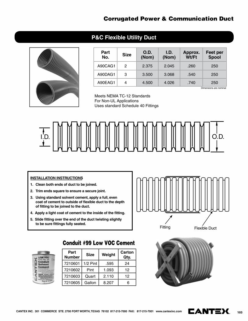
®
CANTEX INC. 301 COMMERCE STE. 2700 FORT WORTH, TEXAS 76102 817-215-7000 FAX: 817-215-7001 www.cantexinc.com
Part No. Size O.D.
(Nom)I.D.
(Nom)Approx.
Wt/FtFeet per
Spool
A90CAG1 2 2.375 2.045 .260 250
A90DAG1 3 3.500 3.068 .540 250
A90EAG1 4 4.500 4.026 .740 250
Meets NEMA TC-12 StandardsFor Non-UL ApplicationsUses standard Schedule 40 Fittings
I.D. O.D.
INSTALLATION INSTRUCTIONS
1. Clean both ends of duct to be joined.
2. Trim ends square to ensure a secure joint.
3. Using standard solvent cement, apply a full, even coat of cement to outside of fl exible duct to the depth of fi tting to be joined to the duct.
4. Apply a light coat of cement to the inside of the fi tting.
5. Slide fi tting over the end of the duct twisting slightly to be sure fi ttings fully seated.
Fitting Flexible Duct
Part Number
Size WeightCarton
Qty.
7210601 1/2 Pint .595 24
7210602 Pint 1.093 12
7210603 Quart 2.110 12
7210605 Gallon 8.207 6
Conduit #99 Low VOC Cement
P&C Flexible Utility Duct
Dimensions are nominal
Corrugated Power & Communication Duct
103


Flexible Electrical Nonmetallic Tubing and Accessories

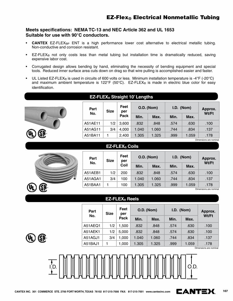
Meets specifi cations: NEMA TC-13 and NEC Article 362 and UL 1653Suitable for use with 90°C conductors.
• CANTEX EZ-FLEX®P ENT is a high performance lower cost alternative to electrical metallic tubing. Non-conductive and corrosion resistant.
• EZ-FLEX® not only costs less than metal tubing but installation time is dramatically reduced, saving expensive labor cost.
• Corrugated design allows bending by hand, eliminating the necessity of bending equipment and special tools. Reduced inner surface area cuts down on drag so that wire pulling is accomplished easier and faster.
• UL Listed EZ-FLEX® is used in circuits of 600 volts or less. Minimum installation temperature is -4°F (-20°C) and maximum ambient temperature is 122°F (50°C). EZ-FLEX® is made in electric blue color for easy identifi cation.
I.D. O.D.
Part No.
SizeFeet per
Pack
O.D. (Nom) I.D. (Nom) Approx. Wt/Ft
Min. Max. Min. Max.
A51AE11 1/2 3,600 .832 .848 .574 .630 .100
A51AG11 3/4 4,000 1.040 1.060 .744 .834 .137
A51BA11 1 2,400 1.305 1.325 .999 1.059 .178
Part No.
SizeFeet per Coil
O.D. (Nom) I.D. (Nom) Approx. Wt/Ft
Min. Max. Min. Max.
A51AEB1 1/2 200 .832 .848 .574 .630 .100
A51AGA1 3/4 100 1.040 1.060 .744 .834 .137
A51BAA1 1 100 1.305 1.325 .999 1.059 .178
Part No.
SizeFeet per
Pack
O.D. (Nom) I.D. (Nom) Approx. Wt/Ft
Min. Max. Min. Max.
A51AEQ1 1/2 1,500 .832 .848 .574 .630 .100
A51AEK1 1/2 5,000 .832 .848 .574 .630 .100
A51AGJ1 3/4 1,000 1.040 1.060 .744 .834 .137
A51BAJ1 1 1,000 1.305 1.325 .999 1.059 .178
EZ-FLEX® Straight 10’ Lengths
EZ-FLEX® Coils
EZ-FLEX® Reels
Dimensions are nominal
Dimensions are nominal
Dimensions are nominal
CANTEX INC. 301 COMMERCE STE. 2700 FORT WORTH, TEXAS 76102 817-215-7000 FAX: 817-215-7001 www.cantexinc.com 107®
EZ-Flex® Electrical Nonmetallic Tubing

Part No.
SizeCarton
Qty.A B C D
5163380 1/2 200 2.000 .700 .850 1.235
5163381 3/4 200 1.957 .894 1.057 1.529
5163382 1 100 2.127 1.123 1.325 1.793
Part No.
SizeCarton
Qty.A B C D
5163415 1/2 200 1.620 14 NPT .600 1.235
5163416 3/4 200 1.548 14 NPT .797 1.529
5163417 1 100 1.763 11-1/2 NPT 1.010 1.793
Part No.
SizeCarton
Qty.A B C D
5163405 1/2 200 1.460 .963 .850 1.235
5163406 3/4 200 1438 1.185 1.057 1.529
5163407 1 100 1.523 1.455 1.325 1.793
ENT Coupling
ENT Male Adapter - Threaded
ENT Male Adapter - Snap In
A
B
C
D
A
C
DB
A C
BD
Dimensions are nominal
Dimensions are nominal
Dimensions are nominal
CANTEX INC. 301 COMMERCE STE. 2700 FORT WORTH, TEXAS 76102 817-215-7000 FAX: 817-215-7001 www.cantexinc.com®
108
Electrical Nonmetallic Accessories
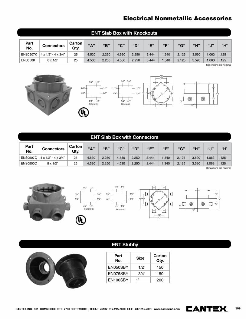
ENT Slab Box with Knockouts
Part No.
ConnectorsCarton
Qty.“A” “B” “C” “D” “E” “F” “G” “H” “J” “H”
ENS0507C 4 x 1/2” - 4 x 3/4” 25 4.530 2.250 4.530 2.250 3.444 1.340 2.125 3.590 1.063 .125
ENS0500C 8 x 1/2” 25 4.530 2.250 4.530 2.250 3.444 1.340 2.125 3.590 1.063 .125
ENT Slab Box with Connectors
Part No.
SizeCarton
Qty.
EN050SBY 1/2” 150
EN075SBY 3/4” 150
EN100SBY 1” 200
ENT Stubby
1/2"
3/4"
ENS0507K ENS0500K
1/2"
1/2"
1/2"
1/2"1/2"
1/2"
1/2" 1/2"
1/2"
1/2"
1/2" 3/4"
3/4"
3/4"
“C” “D” “E”
“B”
“J”“G”
“K”
“A”
“F”
“H”
1/2"
3/4"
ENS0500C ENS0507C
1/2"
1/2"
1/2"
1/2"1/2"
1/2"
1/2" 1/2"
1/2"
1/2"
1/2" 3/4"
3/4"
3/4"
“A” “B” “E”
“J”“G”
“K”
“F”
“H”
“C”“D”
Part No.
ConnectorsCarton
Qty.“A” “B” “C” “D” “E” “F” “G” “H” “J” “H”
ENS0507K 4 x 1/2” - 4 x 3/4” 25 4.530 2.250 4.530 2.250 3.444 1.340 2.125 3.590 1.063 .125
ENS050K 8 x 1/2” 25 4.530 2.250 4.530 2.250 3.444 1.340 2.125 3.590 1.063 .125
Dimensions are nominal
Dimensions are nominal
CANTEX INC. 301 COMMERCE STE. 2700 FORT WORTH, TEXAS 76102 817-215-7000 FAX: 817-215-7001 www.cantexinc.com 109®
Electrical Nonmetallic Accessories
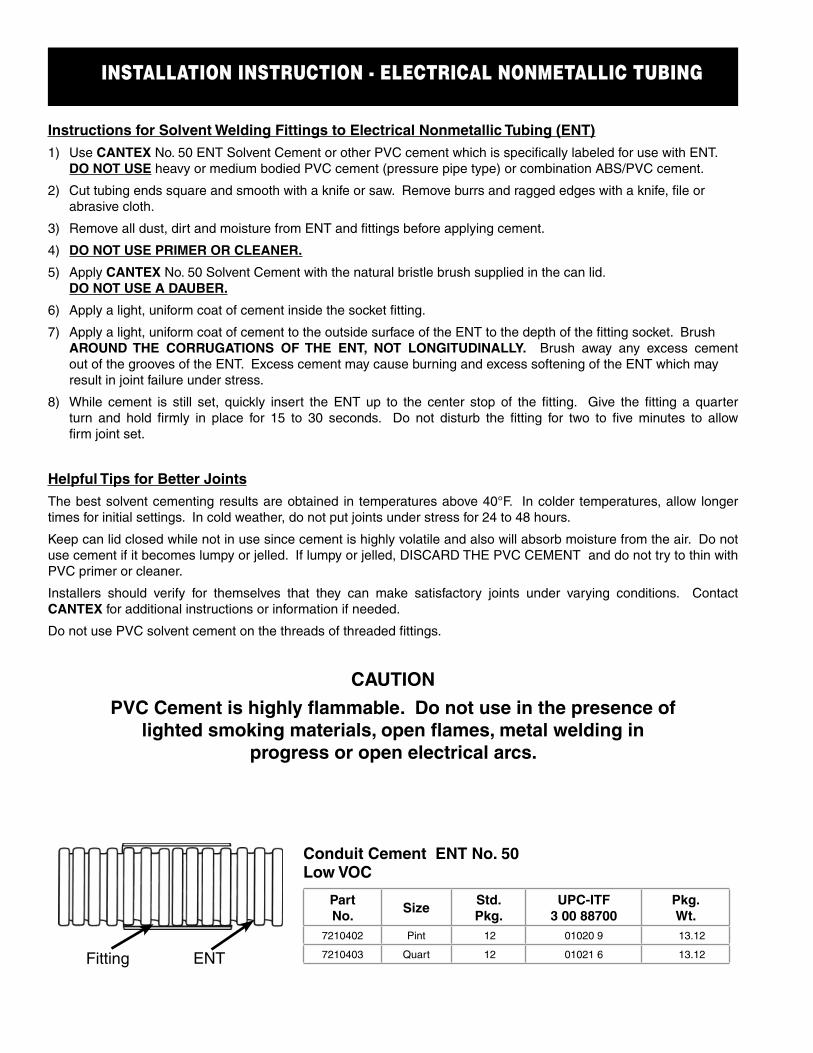
INSTALLATION INSTRUCTION - ELECTRICAL NONMETALLIC TUBING
Instructions for Solvent Welding Fittings to Electrical Nonmetallic Tubing (ENT)
1) Use CANTEX No. 50 ENT Solvent Cement or other PVC cement which is specifi cally labeled for use with ENT. DO NOT USE heavy or medium bodied PVC cement (pressure pipe type) or combination ABS/PVC cement.
2) Cut tubing ends square and smooth with a knife or saw. Remove burrs and ragged edges with a knife, fi le or abrasive cloth.
3) Remove all dust, dirt and moisture from ENT and fi ttings before applying cement.
4) DO NOT USE PRIMER OR CLEANER.
5) Apply CANTEX No. 50 Solvent Cement with the natural bristle brush supplied in the can lid. DO NOT USE A DAUBER.
6) Apply a light, uniform coat of cement inside the socket fi tting.
7) Apply a light, uniform coat of cement to the outside surface of the ENT to the depth of the fi tting socket. Brush AROUND THE CORRUGATIONS OF THE ENT, NOT LONGITUDINALLY. Brush away any excess cement out of the grooves of the ENT. Excess cement may cause burning and excess softening of the ENT which may result in joint failure under stress.
8) While cement is still set, quickly insert the ENT up to the center stop of the fi tting. Give the fi tting a quarter turn and hold fi rmly in place for 15 to 30 seconds. Do not disturb the fi tting for two to fi ve minutes to allow fi rm joint set.
Helpful Tips for Better Joints
The best solvent cementing results are obtained in temperatures above 40°F. In colder temperatures, allow longer times for initial settings. In cold weather, do not put joints under stress for 24 to 48 hours.
Keep can lid closed while not in use since cement is highly volatile and also will absorb moisture from the air. Do not use cement if it becomes lumpy or jelled. If lumpy or jelled, DISCARD THE PVC CEMENT and do not try to thin with PVC primer or cleaner.
Installers should verify for themselves that they can make satisfactory joints under varying conditions. ContactCANTEX for additional instructions or information if needed.
Do not use PVC solvent cement on the threads of threaded fi ttings.
CAUTION
PVC Cement is highly fl ammable. Do not use in the presence of lighted smoking materials, open fl ames, metal welding in
progress or open electrical arcs.
ENTFitting
Part No.
SizeStd.Pkg.
UPC-ITF3 00 88700
Pkg.Wt.
7210402 Pint 12 01020 9 13.12
7210403 Quart 12 01021 6 13.12
Conduit Cement ENT No. 50 Low VOC
Enviro-Flex® Liquidtight Flexible Conduit & Fittings

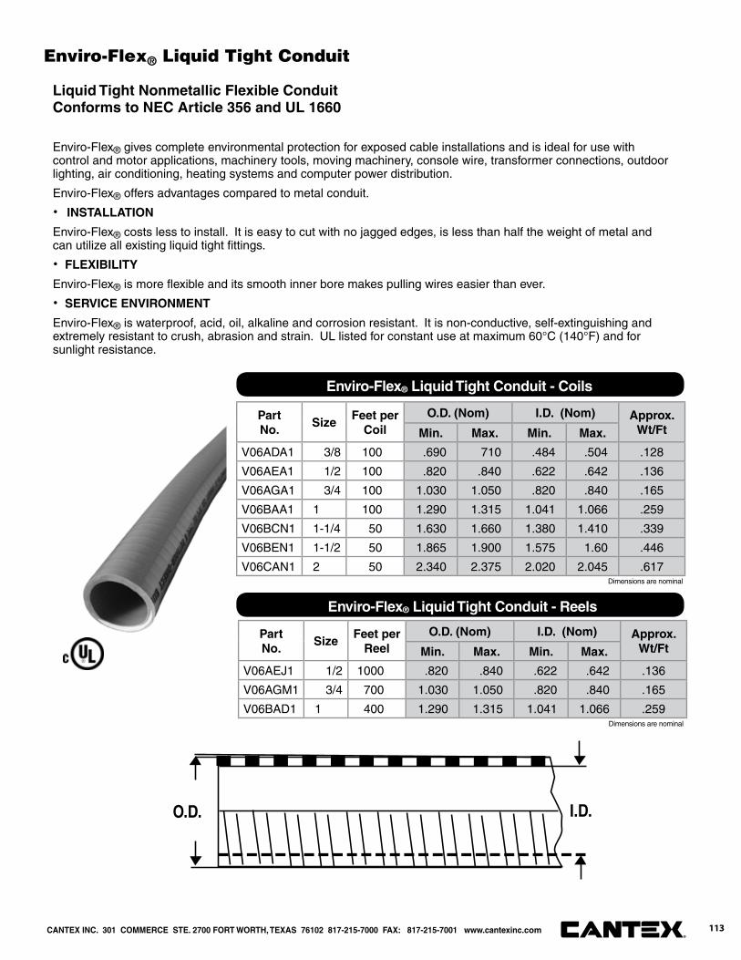
Part No.
SizeFeet per
CoilO.D. (Nom) I.D. (Nom) Approx.
Wt/FtMin. Max. Min. Max.
V06ADA1 3/8 100 .690 710 .484 .504 .128
V06AEA1 1/2 100 .820 .840 .622 .642 .136
V06AGA1 3/4 100 1.030 1.050 .820 .840 .165
V06BAA1 1 100 1.290 1.315 1.041 1.066 .259
V06BCN1 1-1/4 50 1.630 1.660 1.380 1.410 .339
V06BEN1 1-1/2 50 1.865 1.900 1.575 1.60 .446
V06CAN1 2 50 2.340 2.375 2.020 2.045 .617
Enviro-Flex® Liquid Tight Conduit - Coils
Part No.
SizeFeet per
ReelO.D. (Nom) I.D. (Nom) Approx.
Wt/FtMin. Max. Min. Max.
V06AEJ1 1/2 1000 .820 .840 .622 .642 .136
V06AGM1 3/4 700 1.030 1.050 .820 .840 .165
V06BAD1 1 400 1.290 1.315 1.041 1.066 .259
Enviro-Flex® Liquid Tight Conduit - Reels
O.D. I.D.
Dimensions are nominal
Dimensions are nominal
CANTEX INC. 301 COMMERCE STE. 2700 FORT WORTH, TEXAS 76102 817-215-7000 FAX: 817-215-7001 www.cantexinc.com 113®
Enviro-Flex® Liquid Tight Conduit
Liquid Tight Nonmetallic Flexible ConduitConforms to NEC Article 356 and UL 1660
Enviro-Flex® gives complete environmental protection for exposed cable installations and is ideal for use with control and motor applications, machinery tools, moving machinery, console wire, transformer connections, outdoor lighting, air conditioning, heating systems and computer power distribution.
Enviro-Flex® offers advantages compared to metal conduit.
· INSTALLATION
Enviro-Flex® costs less to install. It is easy to cut with no jagged edges, is less than half the weight of metal and can utilize all existing liquid tight fi ttings.
· FLEXIBILITY
Enviro-Flex® is more fl exible and its smooth inner bore makes pulling wires easier than ever.
· SERVICE ENVIRONMENT
Enviro-Flex® is waterproof, acid, oil, alkaline and corrosion resistant. It is non-conductive, self-extinguishing and extremely resistant to crush, abrasion and strain. UL listed for constant use at maximum 60°C (140°F) and for sunlight resistance.

Part No. Size Carton
Qty. A B C
6441000 3/8 100 2.000 .540 1.400
6441001 1/2 100 2.000 .540 1.400
6441002 3/4 50 2.200 .635 1.700
6441003 1 25 2.280 .740 2.000
6441004 1-1/4 25 2.440 .760 2.400
6441005 1-1/2 10 2.700 .800 2.670
6441006 2 10 2.990 .850 3.280
Enviro-Flex® Straight Connectors
Part No. Size Carton
Qty. A B C
5441000 3/4 50 2.120 .500 3.120
5441001 1/2 50 2.120 .500 3.120
5441002 3/4 50 2.500 .520 3.600
5441003 1 25 3.125 .700 4.125
5441004 1-1/4 25 4.450 .760 5.200
5441005 1-1/2 10 4.750 .800 5.200
5441006 2 10 5.420 .860 5.800
Enviro-Flex® 90° Connectors
Part No. Size Carton
Qty.6441101 1/2 8
6441102 3/4 6
6441103 1 6
Enviro-Flex® Flexible Elbows
Part No. Size Carton
Qty.5441051 1/2 4
5441052 3/4 4
Enviro-Flex® Kits
Applications:· HVAC equipment
· Machine tools
· Marine equipment
· Motors and controls
· Printing equipment
· Pumps
· Refrigeration equipment
· Assemblies
· Wire hook-up
Dimensions are nominal
Dimensions are nominal
CANTEX INC. 301 COMMERCE STE. 2700 FORT WORTH, TEXAS 76102 817-215-7000 FAX: 817-215-7001 www.cantexinc.com®
114
Enviro-Flex® Liquid Tight Conduit Fittings
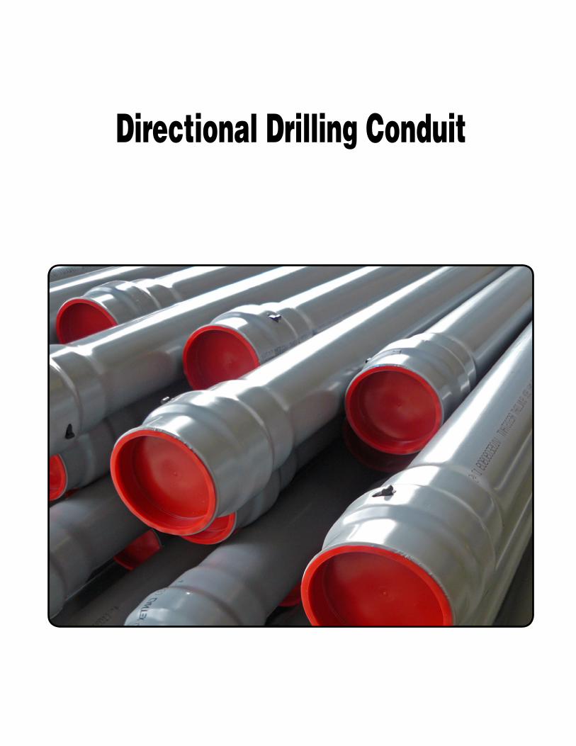
Directional Drilling Conduit

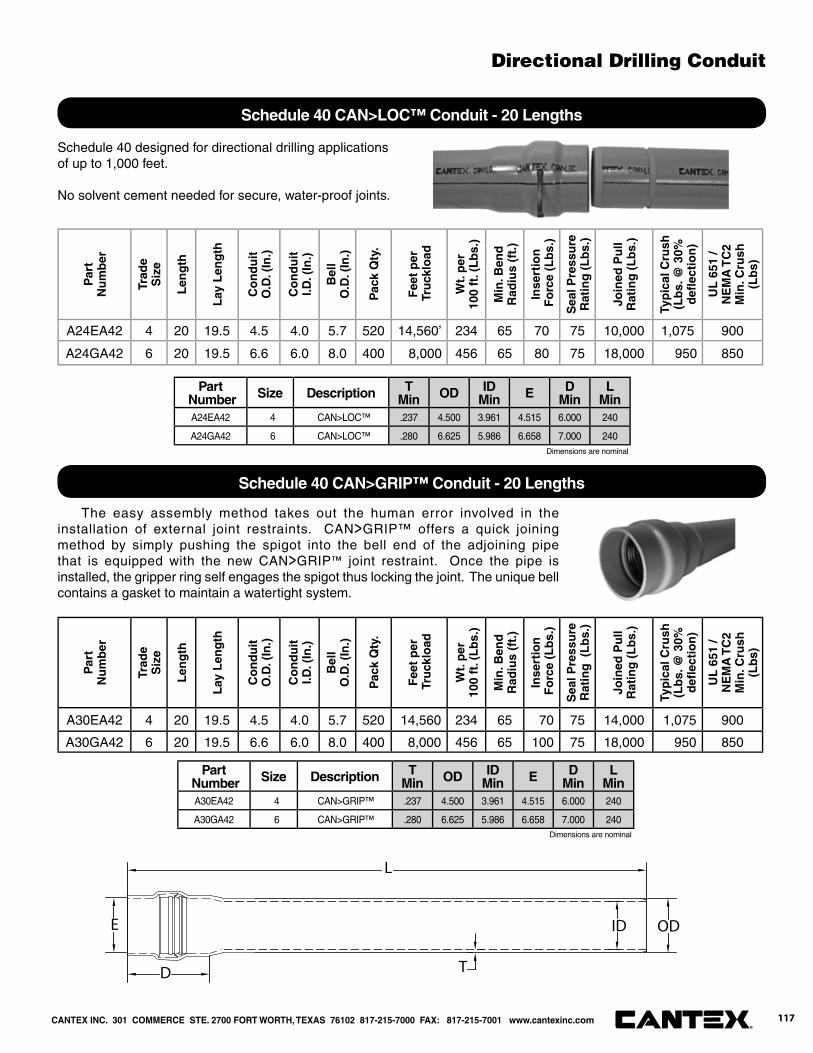
CANTEX INC. 301 COMMERCE STE. 2700 FORT WORTH, TEXAS 76102 817-215-7000 FAX: 817-215-7001 www.cantexinc.com 117®
Schedule 40 designed for directional drilling applications of up to 1,000 feet.
No solvent cement needed for secure, water-proof joints.
Par
t N
um
ber
Trad
eS
ize
Len
gth
Lay
Len
gth
Co
nd
uit
O.D
. (In
.)
Co
nd
uit
I.D. (
In.)
Bel
lO
.D. (
In.)
Pac
k Q
ty.
Fee
t p
er T
ruck
load
Wt.
per
100
ft. (
Lb
s.)
Min
. Ben
dR
adiu
s (f
t.)
Inse
rtio
n F
orc
e (L
bs.
)
Sea
l Pre
ssu
reR
atin
g (
Lb
s.)
Join
ed P
ull
Rat
ing
(L
bs.
)
Typ
ical
Cru
sh
(Lb
s. @
30%
d
efl e
ctio
n)
UL
651
/ N
EM
A T
C2
Min
. Cru
sh
(Lb
s)
A24EA42 4 20 19.5 4.5 4.0 5.7 520 14,560’ 234 65 70 75 10,000 1,075 900
A24GA42 6 20 19.5 6.6 6.0 8.0 400 8,000 456 65 80 75 18,000 950 850
The easy assembly method takes out the human error involved in the installation of external joint restraints. CAN>GRIP™ offers a quick joining method by simply pushing the spigot into the bell end of the adjoining pipe that is equipped with the new CAN>GRIP™ joint restraint. Once the pipe is installed, the gripper ring self engages the spigot thus locking the joint. The unique bell contains a gasket to maintain a watertight system.
Par
t N
um
ber
Trad
eS
ize
Len
gth
Lay
Len
gth
Co
nd
uit
O.D
. (In
.)
Co
nd
uit
I.D. (
In.)
Bel
lO
.D. (
In.)
Pac
k Q
ty.
Fee
t p
er T
ruck
load
Wt.
per
100
ft. (
Lb
s.)
Min
. Ben
dR
adiu
s (f
t.)
Inse
rtio
n F
orc
e (L
bs.
)
Sea
l Pre
ssu
reR
atin
g (
Lb
s.)
Join
ed P
ull
Rat
ing
(L
bs.
)
Typ
ical
Cru
sh
(Lb
s. @
30%
d
efl e
ctio
n)
UL
651
/ N
EM
A T
C2
Min
. Cru
sh
(Lb
s)
A30EA42 4 20 19.5 4.5 4.0 5.7 520 14,560 234 65 70 75 14,000 1,075 900
A30GA42 6 20 19.5 6.6 6.0 8.0 400 8,000 456 65 100 75 18,000 950 850
Schedule 40 CAN>LOC™ Conduit - 20 Lengths
Schedule 40 CAN>GRIP™ Conduit - 20 Lengths
L
D
ODE
T
ID
Part Number Size Description T
Min OD IDMin E D
MinL
MinA30EA42 4 CAN>GRIP™ .237 4.500 3.961 4.515 6.000 240
A30GA42 6 CAN>GRIP™ .280 6.625 5.986 6.658 7.000 240Dimensions are nominal
Part Number Size Description T
Min OD IDMin E D
MinL
MinA24EA42 4 CAN>LOC™ .237 4.500 3.961 4.515 6.000 240
A24GA42 6 CAN>LOC™ .280 6.625 5.986 6.658 7.000 240Dimensions are nominal
Directional Drilling Conduit

Telephone Duct

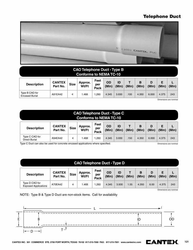
DescriptionCANTEX Part No.
SizeApprox.
Wt/Ft
Feet per
Pack
OD(Min)
ID(Min)
T(Min)
B(Min)
D(Min)
E(Min)
L(Min)
Type C CAO for Direct Burial
A94EA42 4 1.468 1,260 4.345 3.930 .150 4.350 6.000 4.375 243
DescriptionCANTEX Part No.
SizeApprox.
Wt/Ft
Feet per
Pack
OD(Min)
ID(Min)
T(Min)
B(Min)
D(Min)
E(Min)
L(Min)
Type D CAO for Exposed Applications
A70EA42 4 1.468 1,260 4.345 3.930 1.55 4.350 6.00 4.375 243
DescriptionCANTEX Part No.
SizeApprox.
Wt/Ft
Feet per
Pack
OD(Min)
ID(Min)
T(Min)
B(Min)
D(Min)
E(Min)
L(Min)
Type B CAO for Encased Burial
A91EA42 4 1.468 1,260 4.345 3.930 .100 4.350 6.000 4.375 243
NOTE: Type B & Type D Duct are non-stock items. Call for availability
Dimensions are nominal
Dimensions are nominal
Dimensions are nominal
CAO Telephone Duct - Type BConforms to NEMA TC-10
CAO Telephone Duct - Type CConforms to NEMA TC-10
CAO Telephone Duct - Type D
Type C Duct can also be used for concrete encased applications where specifi ed.
L
E B
D T
ID OD
CANTEX INC. 301 COMMERCE STE. 2700 FORT WORTH, TEXAS 76102 817-215-7000 FAX: 817-215-7001 www.cantexinc.com 121®
Telephone Duct
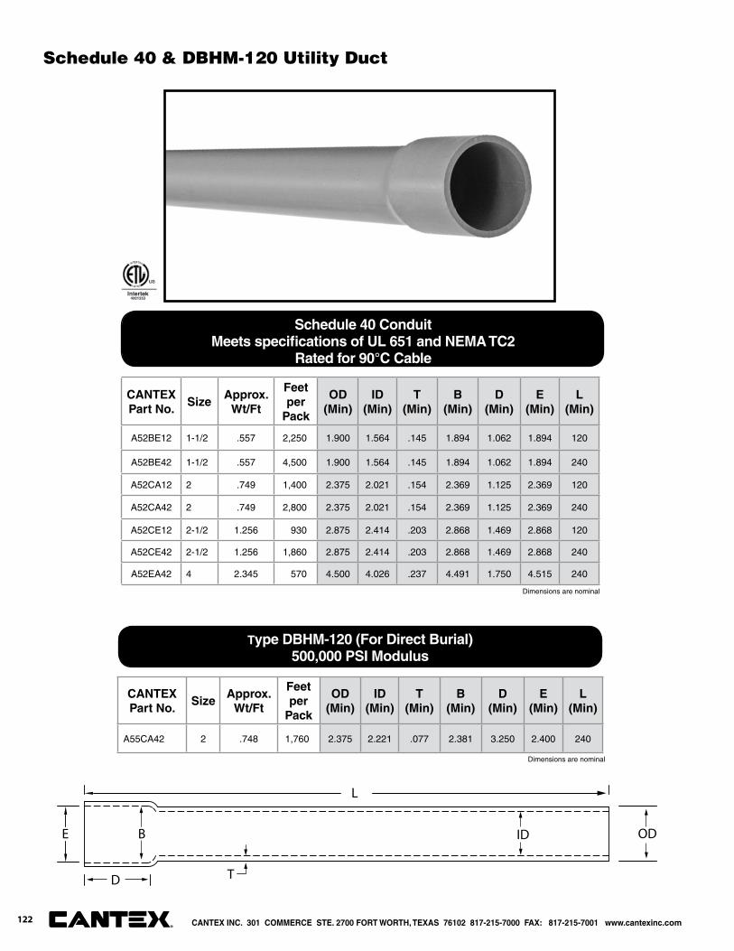
CANTEX Part No.
SizeApprox.
Wt/Ft
Feet per
Pack
OD(Min)
ID(Min)
T(Min)
B(Min)
D(Min)
E(Min)
L(Min)
A52BE12 1-1/2 .557 2,250 1.900 1.564 .145 1.894 1.062 1.894 120
A52BE42 1-1/2 .557 4,500 1.900 1.564 .145 1.894 1.062 1.894 240
A52CA12 2 .749 1,400 2.375 2.021 .154 2.369 1.125 2.369 120
A52CA42 2 .749 2,800 2.375 2.021 .154 2.369 1.125 2.369 240
A52CE12 2-1/2 1.256 930 2.875 2.414 .203 2.868 1.469 2.868 120
A52CE42 2-1/2 1.256 1,860 2.875 2.414 .203 2.868 1.469 2.868 240
A52EA42 4 2.345 570 4.500 4.026 .237 4.491 1.750 4.515 240
CANTEX Part No.
SizeApprox.
Wt/Ft
Feet per
Pack
OD(Min)
ID(Min)
T(Min)
B(Min)
D(Min)
E(Min)
L(Min)
A55CA42 2 .748 1,760 2.375 2.221 .077 2.381 3.250 2.400 240
Dimensions are nominal
Dimensions are nominal
Schedule 40 ConduitMeets specifi cations of UL 651 and NEMA TC2
Rated for 90°C Cable
Type DBHM-120 (For Direct Burial)500,000 PSI Modulus
L
E B
D T
ID OD
CANTEX INC. 301 COMMERCE STE. 2700 FORT WORTH, TEXAS 76102 817-215-7000 FAX: 817-215-7001 www.cantexinc.com®
122
Schedule 40 & DBHM-120 Utility Duct
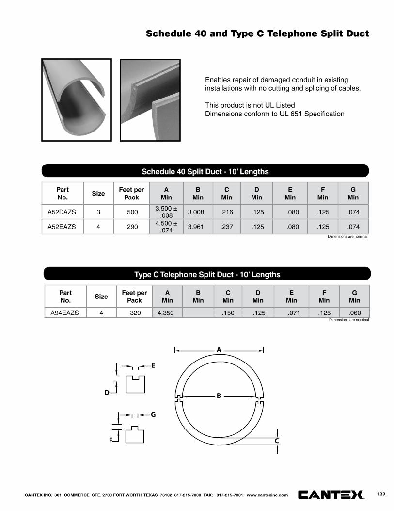
Enables repair of damaged conduit in existing installations with no cutting and splicing of cables.
This product is not UL ListedDimensions conform to UL 651 Specifi cation
Part No.
SizeFeet per
PackA
MinB
MinC
MinD
MinE
MinF
MinG
Min
A52DAZS 3 500 3.500 ±.008 3.008 .216 .125 .080 .125 .074
A52EAZS 4 290 4.500 ±.074 3.961 .237 .125 .080 .125 .074
Part No.
SizeFeet per
PackA
MinB
MinC
MinD
MinE
MinF
MinG
Min
A94EAZS 4 320 4.350 .150 .125 .071 .125 .060
A
B
C
D
E
F
G
Schedule 40 Split Duct - 10’ Lengths
Type C Telephone Split Duct - 10’ Lengths
Dimensions are nominal
Dimensions are nominal
CANTEX INC. 301 COMMERCE STE. 2700 FORT WORTH, TEXAS 76102 817-215-7000 FAX: 817-215-7001 www.cantexinc.com 123®
Schedule 40 and Type C Telephone Split Duct

Part No. SizeApprox.
Wt.Carton
Qty.“L” “W” “A” “B” “D”
“E”(Min.)
“F”(Max.)
5164036S 3-1/4 x 4 .800 24 8.000 4.938 2.500 4.000 4.625 3.000 3.380
5164037 3-1/2 x 4 .800 10 8.000 4.938 2.500 4.000 4.625 3.650 3.250
Part No. SizeApprox.
Wt.Carton
Qty.“A” “B” “C” “D” “L” “W”
5164037 3-1/2”x 4 .800 10 3.000 4.000 4.313 4.375 16.000 4.000
L
D
W
B
A
F E
Dimensions are nominal
L
D
W
Adapts 4” Threaded Metal Pipe to 4” Telephone Duct
Adapts 4” Telephone Duct to Square Clay Tile
Dimensions are nominal
CANTEX INC. 301 COMMERCE STE. 2700 FORT WORTH, TEXAS 76102 817-215-7000 FAX: 817-215-7001 www.cantexinc.com®
124
Telephone Duct - Fittings & Accessories

Part No. SizeApprox.
Wt.Carton
Qty.“W” “L” “B” “D” “E” “R” “T”
5164031S 4 x 3-1/4 x 18 .800 20 4.625 18.000 2.188 3.500 4.375 3.813 3.250
Part No. SizeApprox.
Wt.Carton
Qty.“W” “L” “B” “D” “E” “R”
5164029S 4 x 3-1/2 x 18 .800 8 4.375 18.000 3.000 3.000 4.375 3.750
L
D
WB
RT
E
B
L
D
R
E
W
Dimensions are nominal
Dimensions are nominal
Adapts 4” Telephone Duct to 3-1/4” Round Clay Tile
Adapts 4” Telephone Duct to Split 3-1/2” Square Clay Tile
CANTEX INC. 301 COMMERCE STE. 2700 FORT WORTH, TEXAS 76102 817-215-7000 FAX: 817-215-7001 www.cantexinc.com 125®
Telephone Duct - Fittings & Accessories
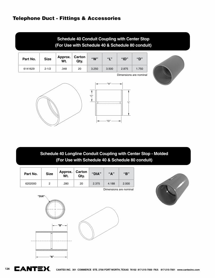
Part No. SizeApprox.
Wt.Carton
Qty.“W” “L” “ID” “D”
6141629 2-1/2 .348 20 3.250 3.500 2.875 1.750
Part No. SizeApprox.
Wt.Carton
Qty.“DIA” “A” “B”
6202000 2 .280 20 2.375 4.188 2.000
“L”
“W”
“D”
“ID”
"A"
“B"
“DIA”
Dimensions are nominal
Dimensions are nominal
Schedule 40 Conduit Coupling with Center Stop
(For Use with Schedule 40 & Schedule 80 conduit)
Schedule 40 Longline Conduit Coupling with Center Stop - Molded
(For Use with Schedule 40 & Schedule 80 conduit)
CANTEX INC. 301 COMMERCE STE. 2700 FORT WORTH, TEXAS 76102 817-215-7000 FAX: 817-215-7001 www.cantexinc.com®
126
Telephone Duct - Fittings & Accessories
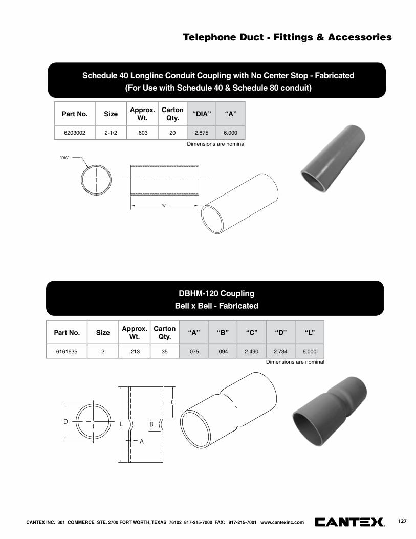
Part No. SizeApprox.
Wt.Carton
Qty.“A” “B” “C” “D” “L”
6161635 2 .213 35 .075 .094 2.490 2.734 6.000
D L
A
B
C
Part No. SizeApprox.
Wt.Carton
Qty.“DIA” “A”
6203002 2-1/2 .603 20 2.875 6.000
"DIA"
"A"
Dimensions are nominal
Dimensions are nominal
Schedule 40 Longline Conduit Coupling with No Center Stop - Fabricated
(For Use with Schedule 40 & Schedule 80 conduit)
DBHM-120 Coupling
Bell x Bell - Fabricated
Telephone Duct - Fittings & Accessories
CANTEX INC. 301 COMMERCE STE. 2700 FORT WORTH, TEXAS 76102 817-215-7000 FAX: 817-215-7001 www.cantexinc.com 127®
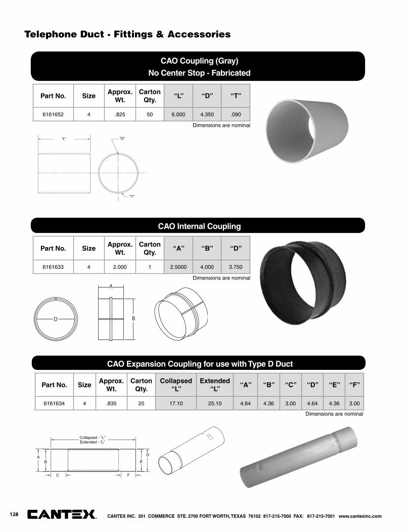
Part No. SizeApprox.
Wt.Carton
Qty.“L” “D” “T”
6161652 4 .825 50 6.000 4.350 .090
Part No. SizeApprox.
Wt.Carton
Qty.“A” “B” “D”
6161633 4 2.000 1 2.5000 4.000 3.750
Part No. SizeApprox.
Wt.Carton
Qty.Collapsed
“L”Extended
“L”“A” “B” “C” “D” “E” “F”
6161634 4 .835 25 17.10 25.10 4.64 4.36 3.00 4.64 4.36 3.00
“L” “D”
“T”
A
BD
Collapsed - “L”Extended - “L”
C F
E
D
BA
Dimensions are nominal
Dimensions are nominal
Dimensions are nominal
CAO Coupling (Gray)
No Center Stop - Fabricated
CAO Internal Coupling
CAO Expansion Coupling for use with Type D Duct
CANTEX INC. 301 COMMERCE STE. 2700 FORT WORTH, TEXAS 76102 817-215-7000 FAX: 817-215-7001 www.cantexinc.com®
128
Telephone Duct - Fittings & Accessories

Part No. SizeApprox.
Wt.Carton
Qty.“L” “W” “D”
5315258 2 .835 25 3.000 2.500 2.000
Part No. SizeApprox.
Wt.Carton
Qty.“L” “W” “H”
5133737 3/4 .000 200 2.500 2.000 1.250
“W”
"L"
“D”
Part No. SizeApprox.
Wt.Carton
Qty.“A” “B”
5140040 4 .835 25 4.500 2.375
"B"
"A"
Dimensions are nominal
Dimensions are nominal
Dimensions are nominal
Schedule 40 End Cap
Poly Plug with Pull Eye
Nonmetallic Conduit Clamp
Flat top
CANTEX INC. 301 COMMERCE STE. 2700 FORT WORTH, TEXAS 76102 817-215-7000 FAX: 817-215-7001 www.cantexinc.com 129®
Telephone Duct - Fittings & Accessories
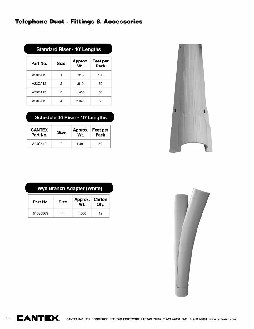
Part No. SizeApprox.
Wt.Carton
Qty.
5163556S 4 4.000 12
Part No. SizeApprox.
Wt.Feet per
Pack
A23BA12 1 .316 100
A23CA12 2 .619 50
A23DA12 3 1.435 50
A23EA12 4 2.045 50
CANTEX Part No.
SizeApprox.
Wt.Feet per
Pack
A25CA12 2 1.401 50
Standard Riser - 10’ Lengths
Schedule 40 Riser - 10’ Lengths
Wye Branch Adapter (White)
Telephone Duct - Fittings & Accessories
CANTEX INC. 301 COMMERCE STE. 2700 FORT WORTH, TEXAS 76102 817-215-7000 FAX: 817-215-7001 www.cantexinc.com®
130
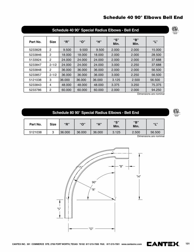
Part No. Size “R” “O” “H”“S”Min.
“B”Min.
“L”
5233828 2 9.500 9.500 9.500 2.000 2.000 15.000
5233846 2 18.000 18.000 18.000 2.000 2.000 28.500
5133924 2 24.000 24.000 24.000 2.000 2.000 37.688
5233847 2-1/2 24.000 24.000 24.000 3.000 2.250 37.688
5233848 2 36.000 36.000 36.000 2.000 2.000 56.500
5233857 2-1/2 36.000 36.000 36.000 3.000 2.250 56.500
5121038 3 36.000 36.000 36.000 3.125 2.500 56.500
5233843 4 48.000 48.000 48.000 3.375 3.250 75.375
5233786 2 60.000 60.000 60.000 2.000 2.000 94.250
90°
"O"
"B"
"R"
"S"
"H"
"L"
Dimensions are nominal
Schedule 40 90° Special Radius Elbows - Bell End
Part No. Size “R” “O” “H”“S”Min.
“B”Min.
“L”
5121038 3 36.000 36.000 36.000 3.125 2.500 56.500
Schedule 80 90° Special Radius Elbows - Bell End
Dimensions are nominal
CANTEX INC. 301 COMMERCE STE. 2700 FORT WORTH, TEXAS 76102 817-215-7000 FAX: 817-215-7001 www.cantexinc.com 131®
Schedule 40 90° Elbows Bell End

Part No. Size “R” “O” “H”“S”Min.
“B”Min.
“L”
5125862 2 18.000 18.000 18.000 2.000 2.000 28.250
5125881 2 24.000 24.000 24.000 2.000 2.000 37.688
5125869 2 36.000 36.000 36.000 2.000 2.000 56.563
5125740 2 48.000 48.000 48.000 2.000 2.000 75.875
5283710 2 68.000 68.000 68.000 2.000 2.000 106.813
90°
"O"
"B"
"R"
"S"
"H"
"L"
Part No. Size “R” “O” “H”“S”Min.
“B”Min.
“L”
5163854Q 4 54.000 54.000 54.000 3.000 6.000 84.688
5163857GQ 4 150.000 150.000 150.000 3.000 6.000 235.625
5163857Q 4 150.000 150.000 150.000 3.000 6.000 235.625Dimensions are nominal
CAO 90° Special Radius Elbows - Bell End
Dimensions are nominal
DBHM-120 90° Special Radius Elbows - Bell End
Telephone Duct - 90° Elbows Bell End
CANTEX INC. 301 COMMERCE STE. 2700 FORT WORTH, TEXAS 76102 817-215-7000 FAX: 817-215-7001 www.cantexinc.com®
132
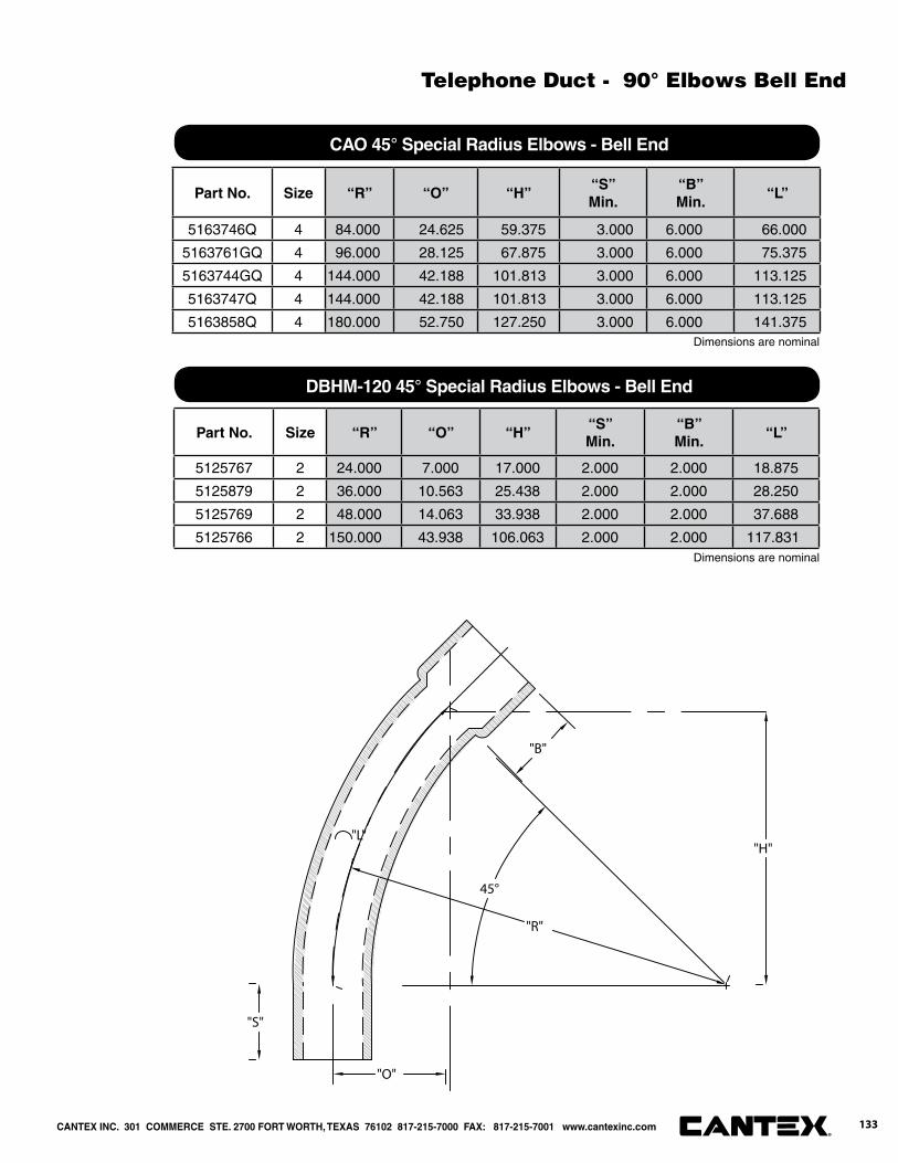
Part No. Size “R” “O” “H”“S”Min.
“B”Min.
“L”
5163746Q 4 84.000 24.625 59.375 3.000 6.000 66.000
5163761GQ 4 96.000 28.125 67.875 3.000 6.000 75.375
5163744GQ 4 144.000 42.188 101.813 3.000 6.000 113.125
5163747Q 4 144.000 42.188 101.813 3.000 6.000 113.125
5163858Q 4 180.000 52.750 127.250 3.000 6.000 141.375
Part No. Size “R” “O” “H”“S”Min.
“B”Min.
“L”
5125767 2 24.000 7.000 17.000 2.000 2.000 18.875
5125879 2 36.000 10.563 25.438 2.000 2.000 28.250
5125769 2 48.000 14.063 33.938 2.000 2.000 37.688
5125766 2 150.000 43.938 106.063 2.000 2.000 117.831
Dimensions are nominal
45°
"B"
"O"
"H""L"
"S"
"R"
CAO 45° Special Radius Elbows - Bell End
Dimensions are nominal
DBHM-120 45° Special Radius Elbows - Bell End
CANTEX INC. 301 COMMERCE STE. 2700 FORT WORTH, TEXAS 76102 817-215-7000 FAX: 817-215-7001 www.cantexinc.com 133®
Telephone Duct - 90° Elbows Bell End
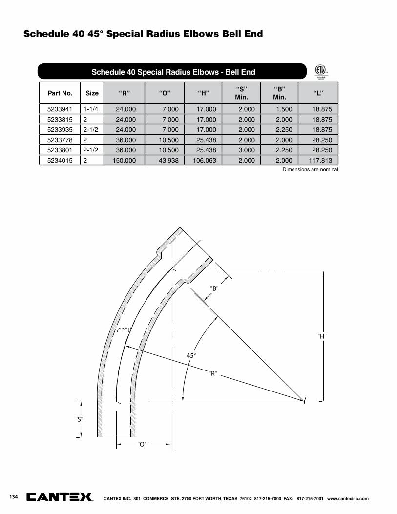
Part No. Size “R” “O” “H”“S”Min.
“B”Min.
“L”
5233941 1-1/4 24.000 7.000 17.000 2.000 1.500 18.875
5233815 2 24.000 7.000 17.000 2.000 2.000 18.875
5233935 2-1/2 24.000 7.000 17.000 2.000 2.250 18.875
5233778 2 36.000 10.500 25.438 2.000 2.000 28.250
5233801 2-1/2 36.000 10.500 25.438 3.000 2.250 28.250
5234015 2 150.000 43.938 106.063 2.000 2.000 117.813
45°
"B"
"O"
"H""L"
"S"
"R"
Dimensions are nominal
Schedule 40 Special Radius Elbows - Bell End
Schedule 40 45° Special Radius Elbows Bell End
CANTEX INC. 301 COMMERCE STE. 2700 FORT WORTH, TEXAS 76102 817-215-7000 FAX: 817-215-7001 www.cantexinc.com®
134
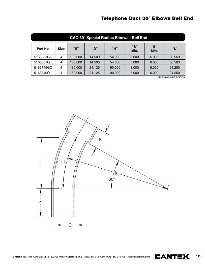
Part No. Size “R” “O” “H”“S”Min.
“B”Min.
“L”
5163881GQ 4 108.000 14.500 54.000 3.000 6.000 56.563
5163881Q 4 108.000 14.500 54.000 3.000 6.000 56.563
5163749GQ 4 180.000 24.125 90.000 3.000 6.000 94.250
5163749Q 4 180.000 24.125 90.000 3.000 6.000 94.250
30°
B
L
S
R
O
H
Dimensions are nominal
CAO 30° Special Radius Elbows - Bell End
Telephone Duct 30° Elbows Bell End
CANTEX INC. 301 COMMERCE STE. 2700 FORT WORTH, TEXAS 76102 817-215-7000 FAX: 817-215-7001 www.cantexinc.com 135®

Part No. Size “R” “O” “H”“S”Min.
“B”Min.
“L”
5163646GQ 4 60 1.125 11.688 3.000 6.000 11.750
Part No. Size “R” “O” “H”“S”Min.
“B”Min.
“L”
5163643GQ 4 150.000 11.438 57.375 3.000 6.000 58.875
5163643Q 4 150.000 11.438 57.375 3.000 6.000 58.875
Part No. Size “R” “O” “H”“S”Min.
“B”Min.
“L”
5125763 2 24.000 1.813 9.188 2.000 2.000 9.438
5125768 2 36.000 2.750 13.750 2.000 2.000 14.125
Part No. Size “R” “O” “H”“S”Min.
“B”Min.
“L”
5233851 2 36.000 2.750 13.750 2.000 2.000 14.125
22.50°
"B"
"L"
"S"
"H"
"O"
"R"
11.25°
"B"
"L"
"S"
"H"
"O"
"R"
Dimensions are nominal
CAO 22-1/2° Special Radius Elbows - Bell End
Dimensions are nominal
DBHM-120 22-1/2° Special Radius Elbows - Bell End
Dimensions are nominal
Schedule 40 22-1/2° Special Radius Elbows - Bell End
Dimensions are nominal
Schedule 40 11-1/4° CAO Special Radius Elbows - Bell End (Gray)
CANTEX INC. 301 COMMERCE STE. 2700 FORT WORTH, TEXAS 76102 817-215-7000 FAX: 817-215-7001 www.cantexinc.com®
136
Telephone Duct - 22-1/2° & 11-1/4° Elbows Bell End
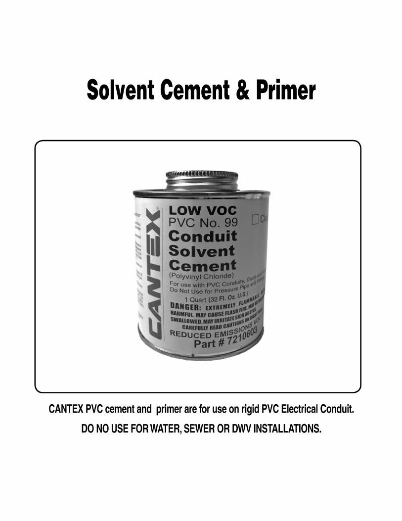
Solvent Cement & Primer
CANTEX PVC cement and primer are for use on rigid PVC Electrical Conduit.
DO NO USE FOR WATER, SEWER OR DWV INSTALLATIONS.

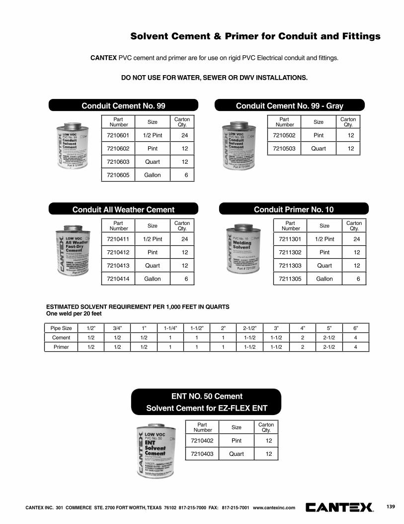
Solvent Cement & Primer for Conduit and Fittings
Part Number Size Carton
Qty.
7210601 1/2 Pint 24
7210602 Pint 12
7210603 Quart 12
7210605 Gallon 6
Conduit Cement No. 99
Part Number Size Carton
Qty.
7210502 Pint 12
7210503 Quart 12
Conduit Cement No. 99 - Gray
Conduit All Weather Cement
Part Number Size Carton
Qty.
7211301 1/2 Pint 24
7211302 Pint 12
7211303 Quart 12
7211305 Gallon 6
Conduit Primer No. 10
Part Number Size Carton
Qty.
7210411 1/2 Pint 24
7210412 Pint 12
7210413 Quart 12
7210414 Gallon 6
CANTEX PVC cement and primer are for use on rigid PVC Electrical conduit and fi ttings.
DO NOT USE FOR WATER, SEWER OR DWV INSTALLATIONS.
ENT NO. 50 Cement
Solvent Cement for EZ-FLEX ENT
Part Number Size Carton
Qty.
7210402 Pint 12
7210403 Quart 12
Pipe Size 1/2” 3/4” 1” 1-1/4” 1-1/2” 2” 2-1/2” 3” 4” 5” 6”
Cement 1/2 1/2 1/2 1 1 1 1-1/2 1-1/2 2 2-1/2 4
Primer 1/2 1/2 1/2 1 1 1 1-1/2 1-1/2 2 2-1/2 4
ESTIMATED SOLVENT REQUIREMENT PER 1,000 FEET IN QUARTSOne weld per 20 feet
CANTEX INC. 301 COMMERCE STE. 2700 FORT WORTH, TEXAS 76102 817-215-7000 FAX: 817-215-7001 www.cantexinc.com 139®

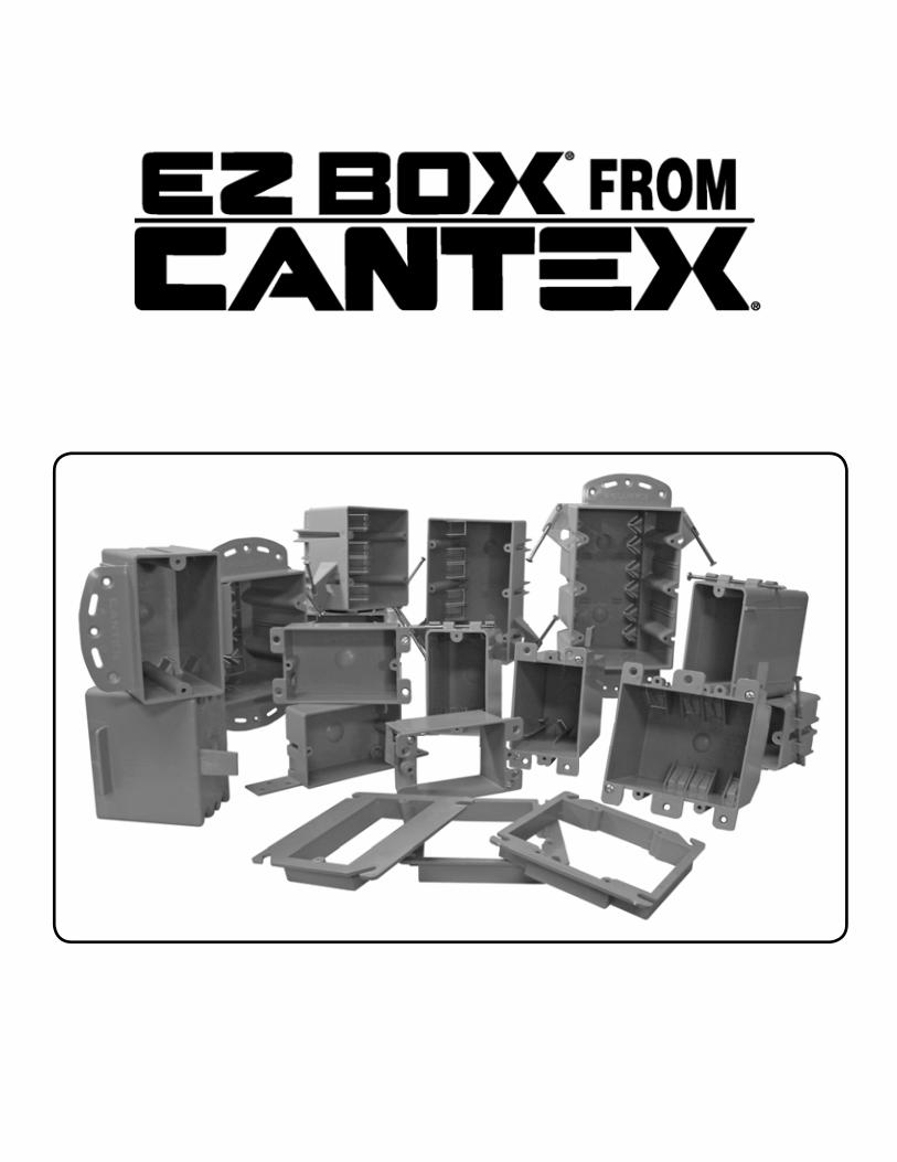

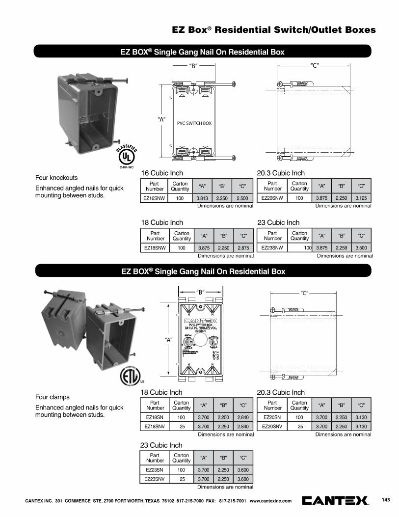
Part Number
CartonQuantity “A” “B” “C”
EZ16SNW 100 3.813 2.250 2.500
“A”
“B” “C”
PVC SWITCH BOX
EZ BOX® Single Gang Nail On Residential Box
16 Cubic Inch
Part Number
CartonQuantity “A” “B” “C”
EZ18SNW 100 3.875 2.250 2.875
18 Cubic Inch
Part Number
CartonQuantity “A” “B” “C”
EZ20SNW 100 3.875 2.250 3.125
20.3 Cubic Inch
Part Number
CartonQuantity “A” “B” “C”
EZ23SNW 100 3.875 2.259 3.500
23 Cubic Inch
Four knockouts
Enhanced angled nails for quickmounting between studs.
2-HR-WC
“C”
“A”
“B”
Part Number
CartonQuantity “A” “B” “C”
EZ18SN 100 3.700 2.250 2.840
EZ18SNV 25 3.700 2.250 2.840
18 Cubic InchPart
NumberCarton
Quantity “A” “B” “C”
EZ20SN 100 3.700 2.250 3.130
EZ20SNV 25 3.700 2.250 3.130
20.3 Cubic Inch
Part Number
CartonQuantity “A” “B” “C”
EZ23SN 100 3.700 2.250 3.600
EZ23SNV 25 3.700 2.250 3.600
23 Cubic Inch
Four clamps
Enhanced angled nails for quickmounting between studs.
EZ BOX® Single Gang Nail On Residential Box
Dimensions are nominal Dimensions are nominal
Dimensions are nominal
Dimensions are nominal Dimensions are nominal
Dimensions are nominalDimensions are nominal
CANTEX INC. 301 COMMERCE STE. 2700 FORT WORTH, TEXAS 76102 817-215-7000 FAX: 817-215-7001 www.cantexinc.com 143®
EZ Box® Residential Switch/Outlet Boxes
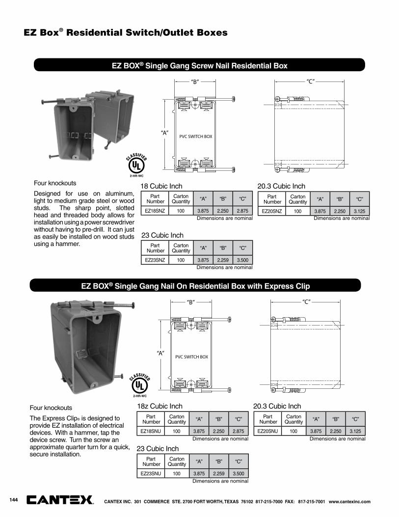
“A”
“B” “C”
PVC SWITCH BOX
EZ BOX® Single Gang Nail On Residential Box with Express Clip
Part Number
CartonQuantity “A” “B” “C”
EZ18SNU 100 3.875 2.250 2.875
Part Number
CartonQuantity “A” “B” “C”
EZ20SNU 100 3.875 2.250 3.125
20.3 Cubic Inch
Part Number
CartonQuantity “A” “B” “C”
EZ23SNU 100 3.875 2.259 3.500
23 Cubic Inch
Four knockouts
The Express Clip® is designed to provide EZ installation of electrical devices. With a hammer, tap the device screw. Turn the screw an approximate quarter turn for a quick, secure installation.
2-HR-WC
18z Cubic Inch
“A”
“B” “C”
PVC SWITCH BOX
EZ BOX® Single Gang Screw Nail Residential Box
Part Number
CartonQuantity “A” “B” “C”
EZ18SNZ 100 3.875 2.250 2.875
18 Cubic InchPart
NumberCarton
Quantity “A” “B” “C”
EZ20SNZ 100 3.875 2.250 3.125
20.3 Cubic Inch
Part Number
CartonQuantity “A” “B” “C”
EZ23SNZ 100 3.875 2.259 3.500
23 Cubic Inch
Four knockouts
Designed for use on aluminum, light to medium grade steel or wood studs. The sharp point, slotted head and threaded body allows for installation using a power screwdriver without having to pre-drill. It can just as easily be installed on wood studs using a hammer.
2-HR-WC
Dimensions are nominal
Dimensions are nominal
Dimensions are nominal
Dimensions are nominal Dimensions are nominal
Dimensions are nominal
CANTEX INC. 301 COMMERCE STE. 2700 FORT WORTH, TEXAS 76102 817-215-7000 FAX: 817-215-7001 www.cantexinc.com®
144
EZ Box® Residential Switch/Outlet Boxes

N N NN
N N NN
TWO GANGSWITCH BOX32 CU.IN.(524 ML) VOL
EZ32ON
PVC
16/1414/1212/10
“A”
“B”
“C” “D”
“F”
“G”
EZ BOX® Two Gang Nail On Residential Box
Part Number
CartonQuantity “A” “B” “C” “D” “E” “F” “G”
EZ32DN 50 3.813 3.938 3.500 3.688 .094 3.063 3.063
32 Cubic InchEight knockouts
Enhanced angled nails for quickmounting between studs.
N N NN
N N NN
TWO GANGSWITCH BOX32 CU.IN.(524 ML) VOL
EZ32ON
PVC
16/1414/1212/10
“A”
“B”
“C” “D”
“F”
“G”
EZ BOX® Two Gang Residential Box with Screw Nail
Part Number
CartonQuantity “A” “B” “C” “D” “E” “F” “G”
EZ32DNZ 50 3.813 3.938 3.500 3.688 .094 3.063 3.063
32 Cubic InchEight knockouts
Enhanced angled nails for quickmounting between studs.
Designed for use on aluminum, light to medium grade steel or wood studs.
Dimensions are nominal
Dimensions are nominal
2-HR-W
2-HR-W
CANTEX INC. 301 COMMERCE STE. 2700 FORT WORTH, TEXAS 76102 817-215-7000 FAX: 817-215-7001 www.cantexinc.com 145®
EZ Box® Residential Switch/Outlet Boxes
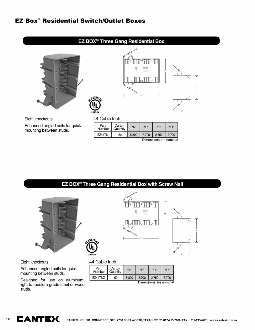
22/1419/1217/10
THREE GANGDEVICE BOX44 CU. IN.(724 ML) VOL.2
"D"
"C"
"A"
"B"
EZ BOX® Three Gang Residential Box
Part Number
CartonQuantity “A” “B” “C” “D”
EZ44TN 50 5.800 3.700 2.750 3.700
44 Cubic InchEight knockouts
Enhanced angled nails for quickmounting between studs.
Dimensions are nominal
2-HR-W
22/1419/1217/10
THREE GANGDEVICE BOX44 CU. IN.(724 ML) VOL.2
"D"
"C"
"A"
"B"
EZ BOX® Three Gang Residential Box with Screw Nail
Part Number
CartonQuantity “A” “B” “C” “D”
EZ44TNZ 50 5.800 3.700 2.750 3.700
44 Cubic InchEight knockouts
Enhanced angled nails for quickmounting between studs.
Designed for use on aluminum, light to medium grade steel or wood studs.
Dimensions are nominal
2-HR-W
CANTEX INC. 301 COMMERCE STE. 2700 FORT WORTH, TEXAS 76102 817-215-7000 FAX: 817-215-7001 www.cantexinc.com®
146
EZ Box® Residential Switch/Outlet Boxes

N N N N N N
N N N N N N
PVC FOUR GANGSWITCH BOX
55 CU. IN. (901 ML) VOL.EZ55QNB
27/1424/12
22/1O
1
"L"
"W" "D"
Part Number
CartonQuantity “L” “W” “D”
EZ55QNB 25 7.625 3.625 2.625
55 Cubic InchTwelve knockouts and adjustable bracket for quick, secure mounting between studs
EZ BOX® Four Gang Residential Box with Nails and Adjustable Bracket
Dimensions are nominal
2-HR-W
Part Number
CartonQuantity “L” “W” “D”
EZ55QNBZ 25 7.625 3.625 2.625
55 Cubic InchTwelve clamps, enhanced angled screw-nails and adjustable bracket provides easy, secure installation.
EZ BOX® Four Gang Residential Box with Screw Nail and Adjustable Bracket
N N N N N N
N N N N N N
PVC FOUR GANGSWITCH BOX
55 CU. IN. (901 ML) VOL.EZ55QNB
27/1424/12
22/1O
1
"L"
"W" "D"
Dimensions are nominal
2-HR-W
CANTEX INC. 301 COMMERCE STE. 2700 FORT WORTH, TEXAS 76102 817-215-7000 FAX: 817-215-7001 www.cantexinc.com 147®
EZ Box® Residential Switch/Outlet Boxes
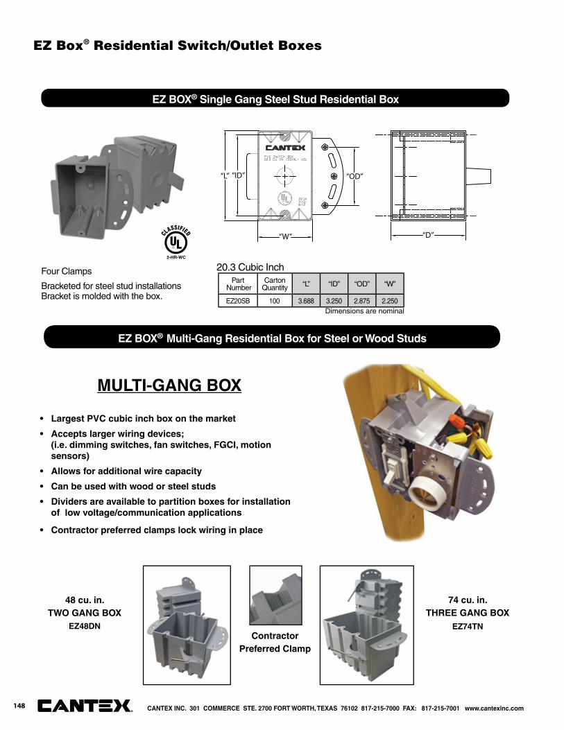
“D”
“OD”“L” “ID”
“W”
EZ BOX® Single Gang Steel Stud Residential Box
Part Number
CartonQuantity “L” “ID” “OD” “W”
EZ20SB 100 3.688 3.250 2.875 2.250
20.3 Cubic InchFour Clamps
Bracketed for steel stud installations Bracket is molded with the box.
2-HR-WC
Dimensions are nominal
MULTI-GANG BOX
• Largest PVC cubic inch box on the market
• Accepts larger wiring devices; (i.e. dimming switches, fan switches, FGCI, motion sensors)
• Allows for additional wire capacity
• Can be used with wood or steel studs
• Dividers are available to partition boxes for installation of low voltage/communication applications
• Contractor preferred clamps lock wiring in place
74 cu. in. THREE GANG BOX
EZ74TN
48 cu. in. TWO GANG BOX
EZ48DNContractor
Preferred Clamp
EZ BOX® Multi-Gang Residential Box for Steel or Wood Studs
CANTEX INC. 301 COMMERCE STE. 2700 FORT WORTH, TEXAS 76102 817-215-7000 FAX: 817-215-7001 www.cantexinc.com®
148
EZ Box® Residential Switch/Outlet Boxes
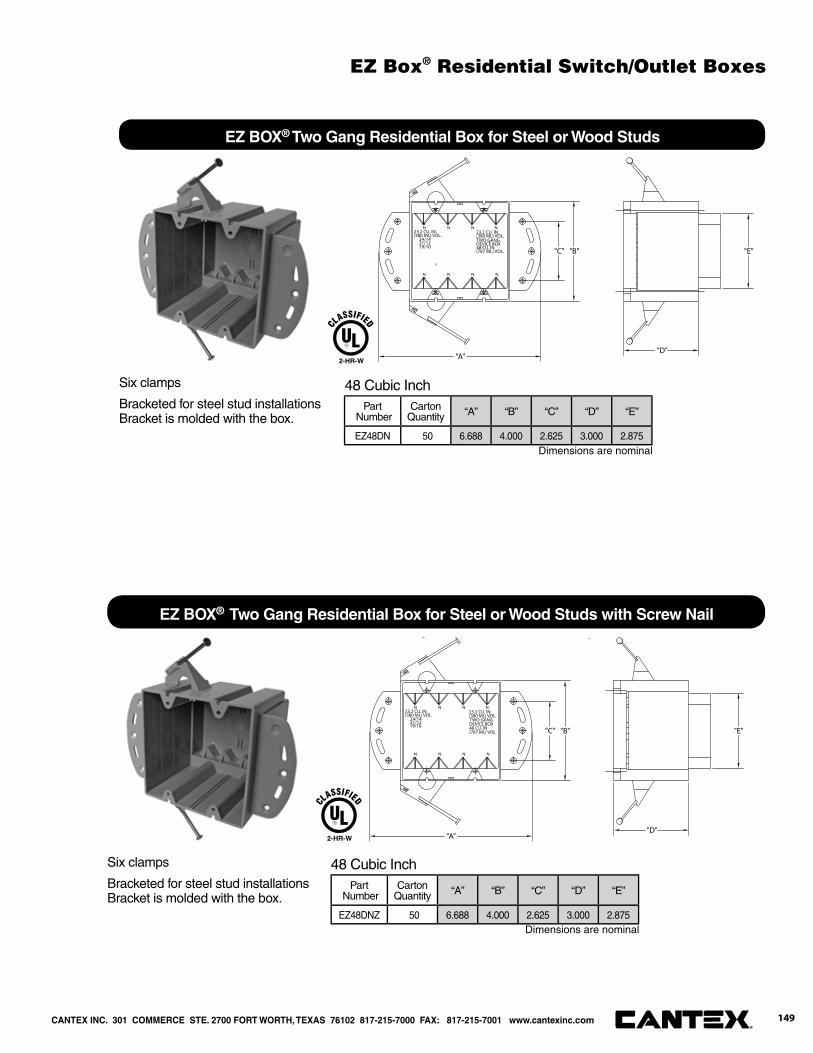
"B"
"A"
"C"
N N N N
N N N N
23.2 CU. IN.(380 ML) VOL. 24/14 21/12 19/10
23.2 CU. IN.(380 ML) VOL.TWO GANG DEVICE BOX48 CU. IN(787 ML) VOL.
8
"D"
"E"
EZ BOX® Two Gang Residential Box for Steel or Wood Studs
Part Number
CartonQuantity “A” “B” “C” “D” “E”
EZ48DN 50 6.688 4.000 2.625 3.000 2.875
48 Cubic InchSix clamps
Bracketed for steel stud installations Bracket is molded with the box.
"B"
"A"
"C"
N N N N
N N N N
23.2 CU. IN.(380 ML) VOL. 24/14 21/12 19/10
23.2 CU. IN.(380 ML) VOL.TWO GANG DEVICE BOX48 CU. IN(787 ML) VOL.
"D"
"E"
EZ BOX® Two Gang Residential Box for Steel or Wood Studs with Screw Nail
Part Number
CartonQuantity “A” “B” “C” “D” “E”
EZ48DNZ 50 6.688 4.000 2.625 3.000 2.875
48 Cubic InchSix clamps
Bracketed for steel stud installations Bracket is molded with the box.
Dimensions are nominal
Dimensions are nominal
2-HR-W
2-HR-W
CANTEX INC. 301 COMMERCE STE. 2700 FORT WORTH, TEXAS 76102 817-215-7000 FAX: 817-215-7001 www.cantexinc.com 149®
EZ Box® Residential Switch/Outlet Boxes
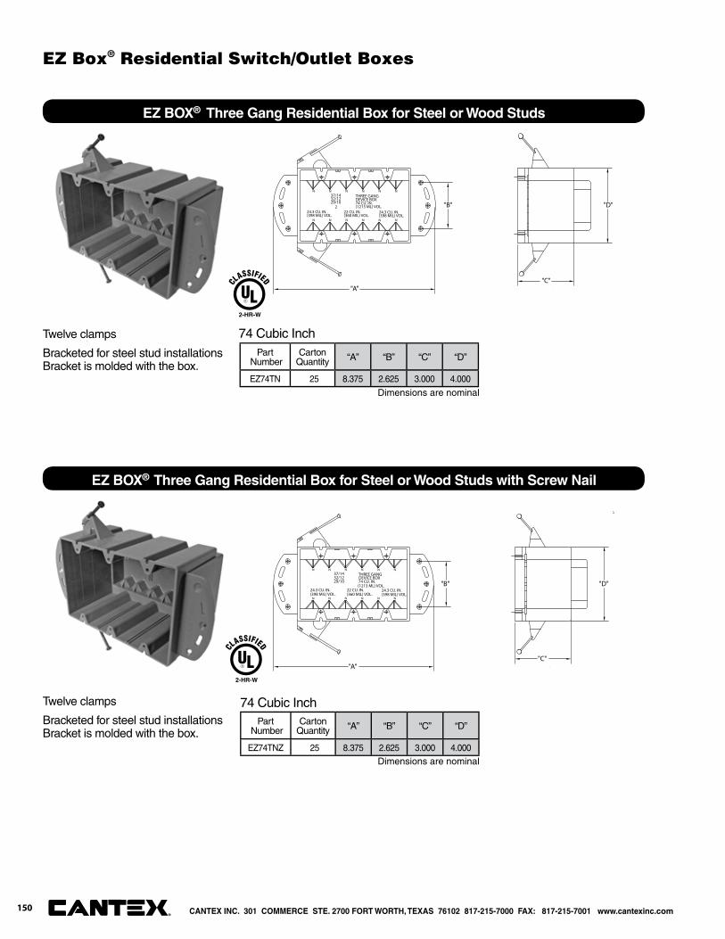
N N N N N N
N N N N N N
37/1432/1229/10
THREE GANGDEVICE BOX74 CU. IN.(1213 ML) VOL.
24.3 CU. IN.(398 MIL) VOL.
22 CU. IN.(360 MIL) VOL.
24.3 CU. IN.(398 MIL) VOL.
"A"
"B"
"C"
"D"2
EZ BOX® Three Gang Residential Box for Steel or Wood Studs
Part Number
CartonQuantity “A” “B” “C” “D”
EZ74TN 25 8.375 2.625 3.000 4.000
74 Cubic InchTwelve clamps
Bracketed for steel stud installations Bracket is molded with the box.
N N N N N N
N N N N N N
37/1432/1229/10
THREE GANGDEVICE BOX74 CU. IN.(1213 ML) VOL.
24.3 CU. IN.(398 MIL) VOL.
22 CU. IN.(360 MIL) VOL.
24.3 CU. IN.(398 MIL) VOL.
"A"
"B"
"C"
"D"
EZ BOX® Three Gang Residential Box for Steel or Wood Studs with Screw Nail
Part Number
CartonQuantity “A” “B” “C” “D”
EZ74TNZ 25 8.375 2.625 3.000 4.000
74 Cubic InchTwelve clamps
Bracketed for steel stud installations Bracket is molded with the box.
Dimensions are nominal
Dimensions are nominal
2-HR-W
2-HR-W
CANTEX INC. 301 COMMERCE STE. 2700 FORT WORTH, TEXAS 76102 817-215-7000 FAX: 817-215-7001 www.cantexinc.com®
150
EZ Box® Residential Switch/Outlet Boxes
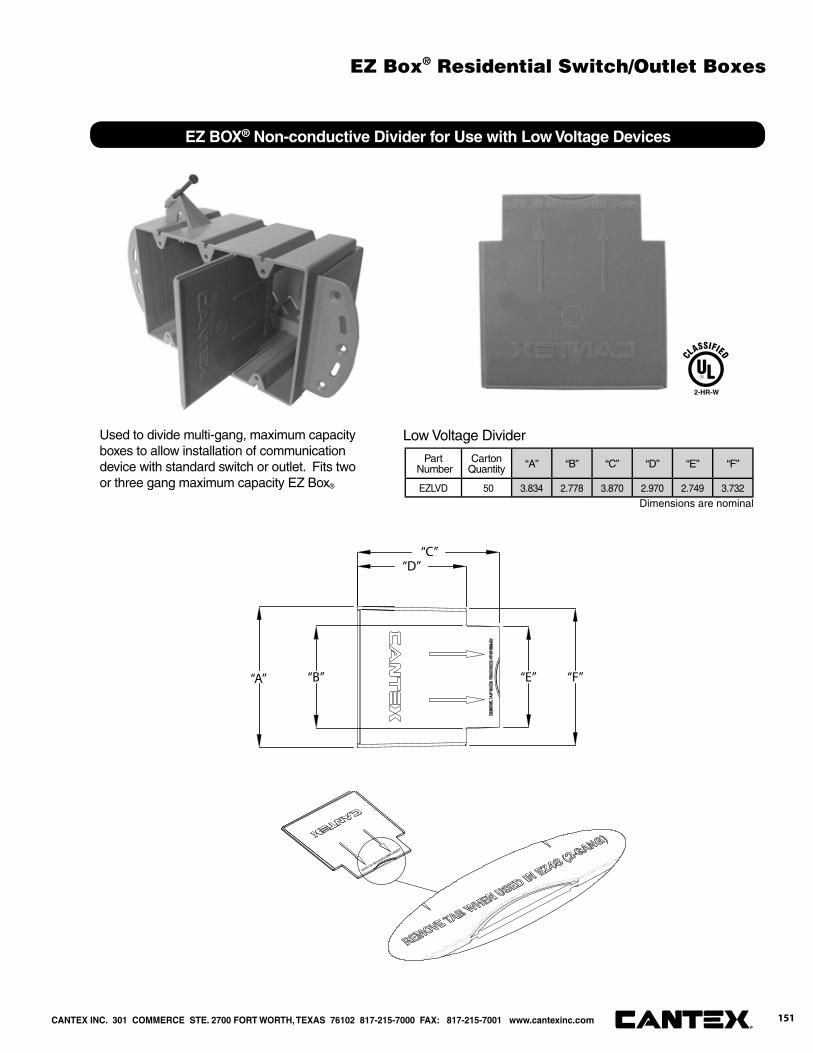
“C”“D”
“A” “B” “E” “F”
EZ BOX® Non-conductive Divider for Use with Low Voltage Devices
Part Number
CartonQuantity “A” “B” “C” “D” “E” “F”
EZLVD 50 3.834 2.778 3.870 2.970 2.749 3.732
Low Voltage DividerUsed to divide multi-gang, maximum capacity boxes to allow installation of communication device with standard switch or outlet. Fits twoor three gang maximum capacity EZ Box®
Dimensions are nominal
2-HR-W
CANTEX INC. 301 COMMERCE STE. 2700 FORT WORTH, TEXAS 76102 817-215-7000 FAX: 817-215-7001 www.cantexinc.com 151®
EZ Box® Residential Switch/Outlet Boxes
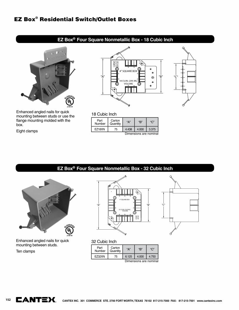
N N
N N
NN
NN
9/148/127/10
18 CU.IN. (295 ML)VOLUME
4" SQUARE BOX
"C""A" "B"
EZ Box® Four Square Nonmetallic Box - 18 Cubic Inch
Part Number
CartonQuantity “A” “B” “C”
EZ18XN 75 4.438 4.000 3.375
18 Cubic InchEnhanced angled nails for quick mounting between studs or use the fl ange mounting molded with the box.
Eight clamps
2-HR-W
N N
N N
NN
NN
"C""A"
N
N
16/1414/1212/10
32 CU.IN. (524 ML)VOLUME
8
4" SQUARE BOX
"B"
EZ Box® Four Square Nonmetallic Box - 32 Cubic Inch
Part Number
CartonQuantity “A” “B” “C”
EZ32XN 75 6.125 4.000 4.750
32 Cubic InchEnhanced angled nails for quick mounting between studs.
Ten clamps
2-HR-W
Dimensions are nominal
Dimensions are nominal
CANTEX INC. 301 COMMERCE STE. 2700 FORT WORTH, TEXAS 76102 817-215-7000 FAX: 817-215-7001 www.cantexinc.com®
152
EZ Box® Residential Switch/Outlet Boxes
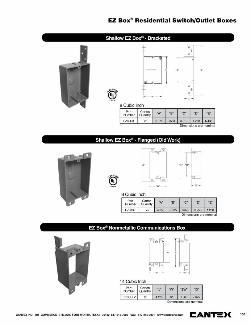
8.0 CU.IN. (131 ML) VOL. "C"
"D"
"B"
"A"
"E"
Shallow EZ Box® - Bracketed
Part Number
CartonQuantity “A” “B” “C” “D” “E”
EZ08SB 25 2.375 3.563 3.313 1.250 6.438
8 Cubic Inch2-HR-W
"A"
"B"
"C" "D"
"E"
Shallow EZ Box® - Flanged (Old Work)
Part Number
CartonQuantity “A” “B” “C” “D” “E”
EZ08SF 75 4.250 2.375 3.875 3.250 1.250
8 Cubic Inch
2-HR-W
“W”
“ID” “L”
“SW”
EZ Box® Nonmetallic Communications Box
Part Number
CartonQuantity “L” “W” “SW” “ID”
EZ10SOLV 25 4.125 .125 1.563 2.875
14 Cubic Inch
Dimensions are nominal
Dimensions are nominal
Dimensions are nominal
CANTEX INC. 301 COMMERCE STE. 2700 FORT WORTH, TEXAS 76102 817-215-7000 FAX: 817-215-7001 www.cantexinc.com 153®
EZ Box® Residential Switch/Outlet Boxes
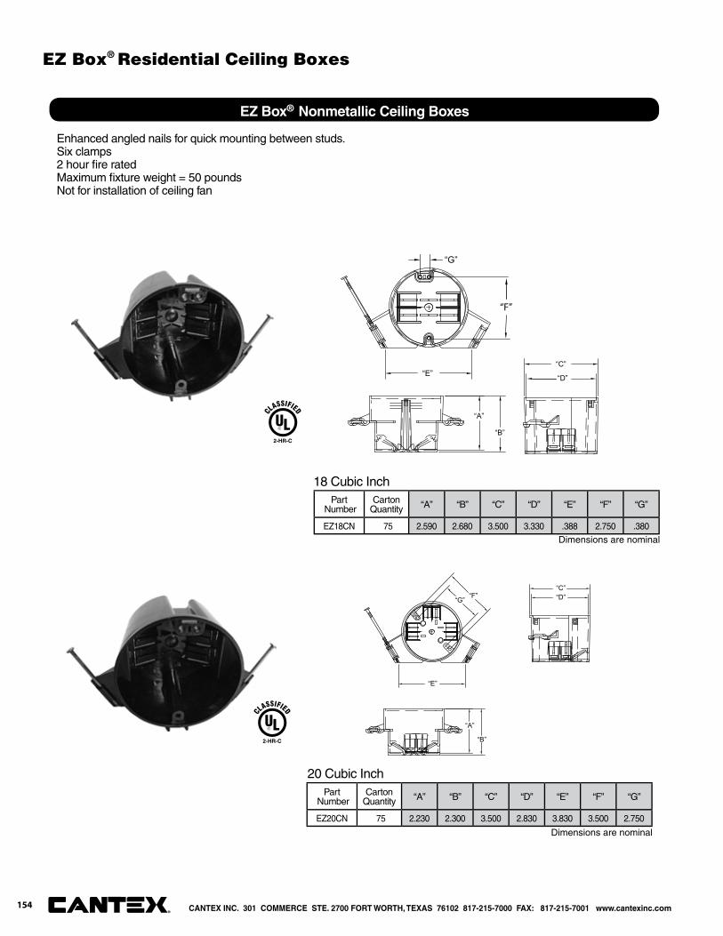
EZ Box® Nonmetallic Ceiling Boxes
Part Number
CartonQuantity “A” “B” “C” “D” “E” “F” “G”
EZ18CN 75 2.590 2.680 3.500 3.330 .388 2.750 .380
18 Cubic Inch
Enhanced angled nails for quick mounting between studs. Six clamps2 hour fi re ratedMaximum fi xture weight = 50 poundsNot for installation of ceiling fan
“B”
“A”
“C”
“E”
“G” “F” “D”
Part Number
CartonQuantity “A” “B” “C” “D” “E” “F” “G”
EZ20CN 75 2.230 2.300 3.500 2.830 3.830 3.500 2.750
20 Cubic Inch
2-HR-C
2-HR-C
“E”
“B”
“A”
“C”
“D”
“F”
“G”
Dimensions are nominal
Dimensions are nominal
CANTEX INC. 301 COMMERCE STE. 2700 FORT WORTH, TEXAS 76102 817-215-7000 FAX: 817-215-7001 www.cantexinc.com®
154
EZ Box® Residential Ceiling Boxes
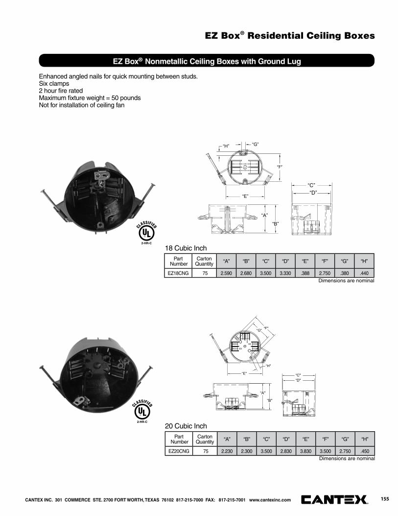
EZ Box® Nonmetallic Ceiling Boxes with Ground Lug
18 Cubic Inch
“B"
“A"
“C"“E"
“G" “F"
“D"
“H"
20 Cubic Inch
2-HR-C
2-HR-C
Enhanced angled nails for quick mounting between studs. Six clamps2 hour fi re ratedMaximum fi xture weight = 50 poundsNot for installation of ceiling fan
Part Number
CartonQuantity “A” “B” “C” “D” “E” “F” “G” “H”
EZ18CNG 75 2.590 2.680 3.500 3.330 .388 2.750 .380 .440
Part Number
CartonQuantity “A” “B” “C” “D” “E” “F” “G” “H”
EZ20CNG 75 2.230 2.300 3.500 2.830 3.830 3.500 2.750 .450
“E”
“B”
“A”
“C”“D”
“F”
“G”“H”
Dimensions are nominal
Dimensions are nominal
CANTEX INC. 301 COMMERCE STE. 2700 FORT WORTH, TEXAS 76102 817-215-7000 FAX: 817-215-7001 www.cantexinc.com 155®
EZ Box® Residential Ceiling Boxes
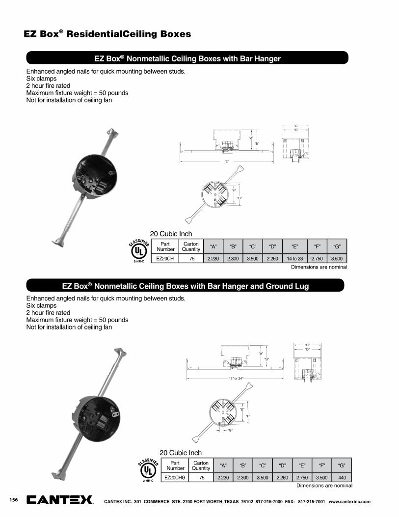
“B”
“A”
“C”
“F"
“G"
“D”
“E”
EZ Box® Nonmetallic Ceiling Boxes with Bar Hanger
Part Number
CartonQuantity “A” “B” “C” “D” “E” “F” “G”
EZ20CH 75 2.230 2.300 3.500 2.260 14 to 23 2.750 3.500
20 Cubic Inch
“B”
“A”
“C”
“E”
“F”
“D”
13" or 24"
“G”
Part Number
CartonQuantity “A” “B” “C” “D” “E” “F” “G”
EZ20CHG 75 2.230 2.300 3.500 2.260 2.750 3.500 .440
20 Cubic Inch
2-HR-C
2-HR-C
Enhanced angled nails for quick mounting between studs. Six clamps2 hour fi re ratedMaximum fi xture weight = 50 poundsNot for installation of ceiling fan
EZ Box® Nonmetallic Ceiling Boxes with Bar Hanger and Ground Lug
Enhanced angled nails for quick mounting between studs. Six clamps2 hour fi re ratedMaximum fi xture weight = 50 poundsNot for installation of ceiling fan
Dimensions are nominal
Dimensions are nominal
CANTEX INC. 301 COMMERCE STE. 2700 FORT WORTH, TEXAS 76102 817-215-7000 FAX: 817-215-7001 www.cantexinc.com®
156
EZ Box® ResidentialCeiling Boxes
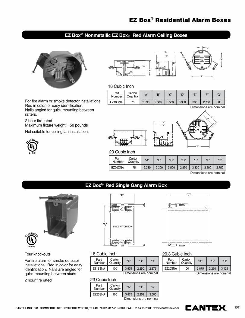
“E”
“B”
“A”
“C”
“D”
“F”
“G”
EZ Box® Nonmetallic EZ Box® Red Alarm Ceiling Boxes
18 Cubic Inch
For fi re alarm or smoke detector installations. Red in color for easy identifi cation.Nails angled for quick mounting between rafters.
2 hour fi re ratedMaximum fi xture weight = 50 pounds
Not suitable for ceiling fan installation.
2-HR-C
“A”
“B” “C”
PVC SWITCH BOX
EZ Box® Red Single Gang Alarm Box
Part Number
CartonQuantity “A” “B” “C”
EZ18SNA 100 3.875 2.250 2.875
Part Number
CartonQuantity “A” “B” “C”
EZ20SNA 100 3.875 2.250 3.125
20.3 Cubic Inch
Part Number
CartonQuantity “A” “B” “C”
EZ23SNA 100 3.875 2.259 3.500
23 Cubic Inch
Four knockouts
For fi re alarm or smoke detector installations. Red in color for easy identifi cation. Nails are angled for quick mounting between studs.
2 hour fi re rated
2-HR-WC
18 Cubic Inch
20 Cubic Inch
Part Number
CartonQuantity “A” “B” “C” “D” “E” “F” “G”
EZ18CNA 75 2.590 2.680 3.500 3.330 .388 2.750 .380
Part Number
CartonQuantity “A” “B” “C” “D” “E” “F” “G”
EZ20CNA 75 2.230 2.300 3.500 2.830 3.830 3.500 2.750
“B”
“A”
“C”
“E”
“G”“F”
“D”
Dimensions are nominal
Dimensions are nominal
Dimensions are nominal
Dimensions are nominal
Dimensions are nominal
CANTEX INC. 301 COMMERCE STE. 2700 FORT WORTH, TEXAS 76102 817-215-7000 FAX: 817-215-7001 www.cantexinc.com 157®
EZ Box® Residential Alarm Boxes
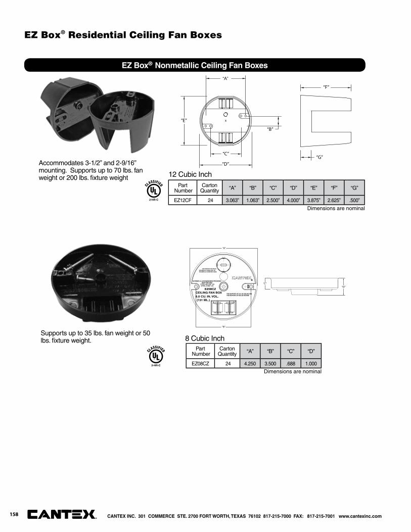
“A”
“B”
“C”
“D”
“E”
“G”
“F”
EZ Box® Nonmetallic Ceiling Fan Boxes
Part Number
CartonQuantity “A” “B” “C” “D” “E” “F” “G”
EZ12CF 24 3.063” 1.063” 2.500” 4.000” 3.875” 2.625” .500”
12 Cubic Inch
Accommodates 3-1/2” and 2-9/16” mounting. Supports up to 70 lbs. fan weight or 200 lbs. fi xture weight
“D”
“B”
“A”
“C”SCREWS & LOCKWASHERS PROVIDED
MUST BE USED1 PCS. #8 X 3/4” LG
2 PCS. #10X2” LG
EZ08CZCEILING FAN BOX8.0 CU. IN. VOL.(131 ML.)
FOR SUPPORT OF 35.0 LB CEILING FAN FOR SUPPORT OF 50.0 LB FIXTURE
FOR USE WITH ELECTRICALNON-METALIC TUBING (ENT) ORNON-METALLIC SHEATHED CABLE
Part Number
CartonQuantity “A” “B” “C” “D”
EZ08CZ 24 4.250 3.500 .688 1.000
8 Cubic InchSupports up to 35 lbs. fan weight or 50 lbs. fi xture weight.
2-HR-C
2-HR-C
Dimensions are nominal
Dimensions are nominal
CANTEX INC. 301 COMMERCE STE. 2700 FORT WORTH, TEXAS 76102 817-215-7000 FAX: 817-215-7001 www.cantexinc.com®
158
EZ Box® Residential Ceiling Fan Boxes
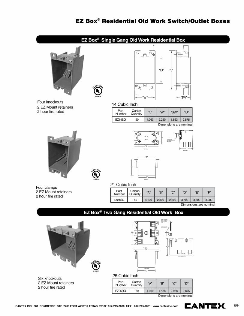
Part Number
CartonQuantity “L” “W” “SW” “ID”
EZ14SO 50 4.063 2.250 1.563 2.875
“W”
“ID” “L”
“SW”
EZ Box® Single Gang Old Work Residential Box
14 Cubic InchFour knockouts2 EZ Mount retainers2 hour fi re rated
Part Number
CartonQuantity “A” “B” “C” “D” “E” “F”
EZ21SO 50 4.100 2.300 2.200 3.700 3.500 3.000
Installation
Wings (2)Securement
Top ViewEnd View
Side View
“A”
“B”
“C”
“D”
“E”
“F”
21 Cubic InchFour clamps2 EZ Mount retainers2 hour fi re rated
Part Number
CartonQuantity “A” “B” “C” “D”
EZ25DO 50 4.000 4.188 2.938 2.875
LEFT SIDE VIEW
END VIEW
TOP VIEW
#6 x 1-1/2" SheetMetal Screw, PanHead, w/combohead
Box Locking Clip(2)Req'd Per Box
“A”
“B”
“C”
“D”
EZ Box® Two Gang Residential Old Work Box
25 Cubic InchSix knockouts2 EZ Mount retainers2 hour fi re rated
2-HR-W
2-HR-W
Dimensions are nominal
Dimensions are nominal
Dimensions are nominal
2-HR-W
CANTEX INC. 301 COMMERCE STE. 2700 FORT WORTH, TEXAS 76102 817-215-7000 FAX: 817-215-7001 www.cantexinc.com 159®
EZ Box® Residential Old Work Switch/Outlet Boxes

Part Number
CartonQuantity “A” “B” “C” “D” “E” “F”
EZ18CO 100 2.680 5.600 3.250 3.500 2.750 4.400
“F”
“C”
“B”“A”
“D”
“E”
EZ Box® Round Old Work Residential Box
18 Cubic InchFour knockouts
3 EZ Mount retainers
2 hour fi re ratedMaximum fi xture weight = 6 pounds
Not suitable for fi xture support or ceiling fan installation.
2-HR-WC
Part Number
CartonQuantity “A” “B” “C” “D” “E” “F” “G”
EZ18COG 100 2.680 5.600 3.250 3.500 2.750 4.400 .500
“F”“C”
“A”“B”“D”
“E”
“G”
18 Cubic Inch with Ground LugFour knockouts
3 EZ Mount retainers
2 hour fi re ratedMaximum fi xture weight = 6 pounds
Not suitable for fi xture support or ceiling fan installation.
2-HR-WC
Dimensions are nominal
Dimensions are nominal
CANTEX INC. 301 COMMERCE STE. 2700 FORT WORTH, TEXAS 76102 817-215-7000 FAX: 817-215-7001 www.cantexinc.com®
160
EZ Box® Residential Old Work Ceiling Boxes
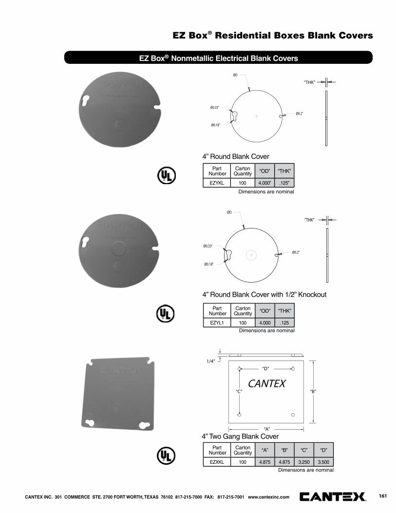
Part Number
CartonQuantity “OD” “THK”
EZYKL 100 4.000” .125”
EZ Box® Nonmetallic Electrical Blank Covers
4” Round Blank Cover
4” Round Blank Cover with 1/2” Knockout
Part Number
CartonQuantity “A” “B” “C” “D”
EZXKL 100 4.875 4.875 3.250 3.500
CANTEX
1/4"“D”
“C” “B”
“A”
4” Two Gang Blank Cover
Dimensions are nominal
Dimensions are nominal
“THK”
ØD
Ø0.2"
Ø0.33"
Ø0.18"
"THK"
ØD
Ø0.2"
Ø0.33"
Ø0.18"
Part Number
CartonQuantity “OD” “THK”
EZYL1 100 4.000 .125
Dimensions are nominal
CANTEX INC. 301 COMMERCE STE. 2700 FORT WORTH, TEXAS 76102 817-215-7000 FAX: 817-215-7001 www.cantexinc.com 161®
EZ Box® Residential Boxes Blank Covers
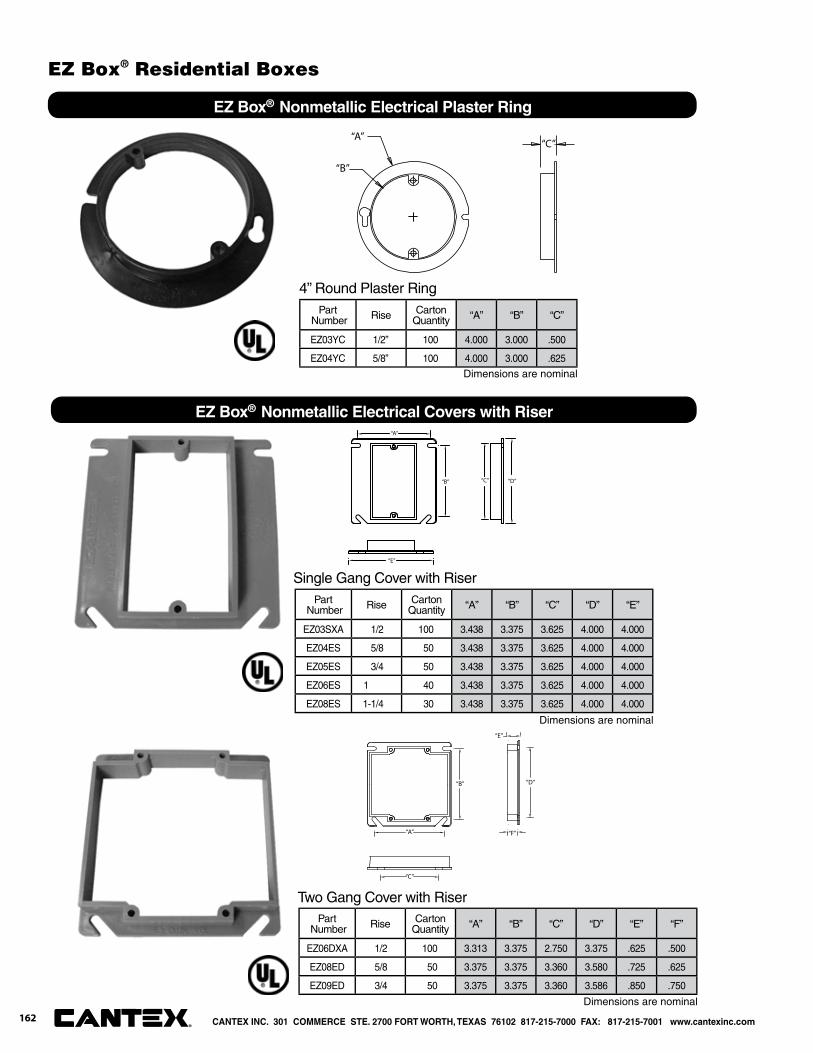
Part Number Rise Carton
Quantity “A” “B” “C”
EZ03YC 1/2” 100 4.000 3.000 .500
EZ04YC 5/8” 100 4.000 3.000 .625
“A”
“B”
“C”
EZ Box® Nonmetallic Electrical Plaster Ring
4” Round Plaster Ring
Part Number Rise Carton
Quantity “A” “B” “C” “D” “E”
EZ03SXA 1/2 100 3.438 3.375 3.625 4.000 4.000
EZ04ES 5/8 50 3.438 3.375 3.625 4.000 4.000
EZ05ES 3/4 50 3.438 3.375 3.625 4.000 4.000
EZ06ES 1 40 3.438 3.375 3.625 4.000 4.000
EZ08ES 1-1/4 30 3.438 3.375 3.625 4.000 4.000
“A”
“B” “C” “D”
“E”
Single Gang Cover with Riser
EZ Box® Nonmetallic Electrical Covers with Riser
Part Number Rise Carton
Quantity “A” “B” “C” “D” “E” “F”
EZ06DXA 1/2 100 3.313 3.375 2.750 3.375 .625 .500
EZ08ED 5/8 50 3.375 3.375 3.360 3.580 .725 .625
EZ09ED 3/4 50 3.375 3.375 3.360 3.586 .850 .750
“A”
“B”
“C”
“D”
“E”
“F”
Two Gang Cover with Riser
Dimensions are nominal
Dimensions are nominal
Dimensions are nominal
CANTEX INC. 301 COMMERCE STE. 2700 FORT WORTH, TEXAS 76102 817-215-7000 FAX: 817-215-7001 www.cantexinc.com®
162
EZ Box® Residential Boxes
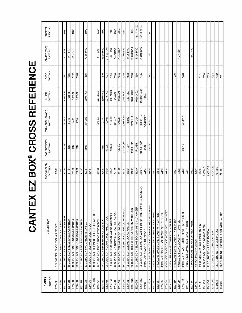
CA
NTE
X
PA
RT
NO
.D
ES
CR
IPT
ION
T&
B /
CA
RLO
N
PAR
T N
O.
T&
B /
BO
WE
RS
PA
RT
NO
.T
&B
/ C
HA
LLE
NG
ER
PA
RT
NO
.A
LLIE
DPA
RT
NO
.R
AC
O
PAR
T N
O.
SLA
TE
R (P
&S
)PA
RT
NO
.T
HE
PIT
TPA
RT
NO
.
EZ
08S
F8
CU
BIC
INC
H F
LAN
GE
D S
HA
LLO
W B
OX
B10
8R
EZ
08S
B8
CU
BIC
INC
H B
RA
CK
ET
ED
SH
ALL
OW
BO
XB
108B
EZ
14S
O14
CU
BIC
INC
H S
ING
LE G
AN
G O
LD W
OR
K B
OX
B11
4R11
4-0W
6070
-493
63-E
W78
87S
1-18
-W16
90
EZ
16S
N16
CU
BIC
INC
H S
ING
LE G
AN
G N
AIL
-ON
BO
XB
116A
116N
SN
-16
1085
-N73
55P
1-16
-R
EZ
18S
N18
CU
BIC
INC
H S
ING
LE G
AN
G N
AIL
-ON
BO
XB
118A
118N
SN
-18
1086
-N73
02P
1-18
-R18
00
EZ
20S
N20
CU
BIC
INC
H S
ING
LE G
AN
G N
AIL
-ON
BO
XB
120A
120N
1050
1088
-N78
20
EZ
23S
N23
CU
BIC
INC
H S
ING
LE G
AN
G N
AIL
-ON
BO
XB
122A
EZ
32D
N32
CU
BIC
INC
H T
WO
GA
NG
NA
IL-O
N B
OX
B23
2A23
4NS
N-2
3223
00-N
C4
7835
P2-
35-R
AC
3600
EZ
18C
O18
CU
BIC
INC
H O
LD W
OR
K C
EIL
ING
BO
XB
618R
EZ
18C
OG
18 C
UB
IC IN
CH
OLD
WO
RK
CE
ILIN
G B
OX
W/G
RD
LU
G
EZ
25D
O25
CU
BIC
INC
H T
WO
GA
NG
OLD
WO
RK
BO
XB
225R
6062
-493
12-B
WK
S2-
32-W
3490
EZ
44T
N44
CU
BIC
INC
H T
HR
EE
GA
NG
NA
IL-O
N B
OX
B34
4A34
5N10
43-C
3300
-NC
678
46S
3-54
-RA
C46
00
EZ
32X
N32
CU
BIC
INC
H 4
SQ
UA
RE
DE
EP
NA
IL-O
N B
OX
B43
2A45
-32N
4000
-N93
43-N
C2
7234
S44
-35-
RA
C
EZ
55Q
NB
55 C
UB
IC IN
CH
FO
UR
GA
NG
NA
IL O
N &
BR
AC
KE
TB
455A
4605
B70
74-B
H33
00-N
BC
476
44S
468-
RA
C61
00
EZ
18X
N18
CU
BIC
INC
H 4
SQ
UA
RE
SH
ALL
OW
NA
IL-O
N B
OX
B41
8AS
N-4
1893
40-C
272
18S
4421
RA
C19
00
EZ
18C
N18
CU
BIC
INC
H C
EIL
ING
BO
X 3
/0 N
AIL
-ON
B51
8A3R
-16N
3090
-N93
55-N
C2
7118
C1-
18-R
AC
1631
0
EZ
18C
NG
18 C
UB
IC IN
CH
CE
ILIN
G B
OX
3/0
NA
IL-O
N W
/GR
D L
UG
B51
8P3R
-16N
GP
3090
-N-4
093
35-N
GC
279
18C
1-19
-RG
AC
1631
1
EZ
20C
N20
CU
BIC
INC
H C
EIL
ING
BO
X 4
/0 N
AIL
-ON
B52
0A4R
-20N
4170
-C93
51-N
C2
7163
A1-
20-R
AC
EZ
20C
NG
20 C
UB
IC IN
CH
CE
ILIN
G B
OX
4/0
NA
IL O
N W
/GR
D L
UG
B52
0P4R
-20N
GP
4170
-C-4
093
51-N
GC
278
23S
1-20
-RG
AC
1611
0
EZ
20C
H20
CU
BIC
INC
H C
EIL
ING
BO
X W
/14
1/4”
-23
1/2”
HA
NG
ER
B62
0H4R
-20B
H40
70-9
493
50-2
4C2
7335
S1-
20-H
AC
1611
7/ 1
6122
EZ
20C
HG
20 C
UB
IC IN
CH
CE
ILIN
G B
OX
W/4
1/4
”-23
1/2
” HA
NG
ER
WIT
H G
RO
UN
D L
UG
B62
0HG
4R-2
0BH
GP
4070
-94-
4093
50-2
4GC
279
35S
1-20
-HG
AC
1611
8/ 1
6123
EZ
XK
L4”
SQ
UA
RE
2 G
AN
G B
LAN
K C
OV
ER
A40
04S
-B*4
041/
45P
B93
44
EZ
03S
XA
4” S
QU
AR
E S
ING
LE G
AN
G S
QU
AR
E C
OV
ER
W/1
/2” R
ISE
RA
410
4S-1
G*4
042-
1277
72R
C1
1010
EZ
04E
S4”
SQ
UA
RE
SIN
GLE
GA
NG
CO
VE
R W
ITH
5/8
” RIS
ER
A41
170
71
EZ
05E
S4”
SQ
UA
RE
SIN
GLE
GA
NG
CO
VE
R W
ITH
3/4
” RIS
ER
A41
2
EZ
06E
S4”
SQ
UA
RE
SIN
GLE
GA
NG
CO
VE
R W
ITH
1” R
ISE
RA
413
EZ
08E
S4”
SQ
UA
RE
SIN
GLE
GA
NG
CO
VE
R W
ITH
1 1
/4” R
ISE
RA
414
EZ
06D
XA
4” S
QU
AR
E 2
GA
NG
CO
VE
R W
ITH
1/4
” RIS
ER
EZ
08E
D4”
SQ
UA
RE
2 G
AN
G C
OV
ER
WIT
H 5
/8” R
ISE
RA
421
7076
EZ
09E
D4”
SQ
UA
RE
2 G
AN
G C
OV
ER
WIT
H 3
/4” R
ISE
RA
422
4SP
1-21
4
EZ
06D
XA
4” S
QU
AR
E 2
GA
NG
SQ
UA
RE
CO
VE
R W
/1/2
” RIS
ER
A42
04S
-2G
*402
2-12
7778
EZ
03Y
C4”
RO
UN
D P
LAS
TE
R R
ING
WIT
H 1
/2” R
ISE
RA
471
EZ
04Y
C4”
RO
UN
D P
LAS
TE
R R
ING
WIT
H 5
/8” R
ISE
RA
472
4SP
2-31
R
EZ
YK
L4”
RO
UN
D B
LAN
K C
OV
ER
E46
0
EZ
YL1
4” R
OU
ND
BLA
NK
CO
VE
R W
ITH
KN
OC
KO
UT
A47
0D70
81
EN
18S
B18
CU
BIC
INC
H S
ING
LE G
AN
G E
NT
BO
XA
5838
1D/
7050
EN
22D
B22
.5 C
UB
IC IN
CH
2 G
AN
G E
NT
BO
XA
A52
1DE
7053
EN
31D
B31
CU
BIC
INC
H 2
GA
NG
EN
T B
OX
A52
17D
E70
54
EN
20C
B20
.3 C
UB
IC IN
CH
EN
T C
EIL
ING
BO
XA
615D
E70
52
EN
20C
H20
.3 C
UB
IC IN
CH
EN
T C
EIL
ING
BO
X W
ITH
HA
NG
ER
A61
5DH
7051
CA
NTE
X E
Z B
OX
® C
RO
SS
RE
FER
EN
CE


Installation Guidelines
Engineering & Design Information
Product Warranty
Authorized Distributor Policy
Conduit Installation Guidelines
166
Scope: For the purpose of general use and installation information, conduit is defi ned as a PVC tube in nominal sizes of ½” through 6”, to be used in non-pressure applications to provide containment of raceways for electrical power wire and cable, communications wiring or fi ber optic cables. Conduit products are not intended for the transport of potable water, sewage or drain water, air or other gasses or corrosive liquids.
1.0 Transportation, Handling and Storage 1.1 Transportation: CANTEX conduit should be transported in modules or bundles in a straight and level position. When possible, larger diameter and heavy walled conduit should be loaded fi rst on the truck or trailer when multiple modules must be loaded. Each vertical stack of modules should be secured with at least two nylon straps or slings at least 4” in width with only enough tightening pressure on the straps to ensure a secure load. Chains and metal strapping should be avoided to secure conduit loads to the transporting vehicle. 1.2 Handling: Conduit should be unloaded one module at a time with a fork lift or backhoe equipped with forks. If unloaded using slings, two slings should be used and positioned so that the center of gravity of the module is centered on the lifting equipment. Personnel on the ground around the unloading site should be kept clear of the load to prevent injury in the event of an equipment failure or shifting of the load. Do not push modules from the vehicle to the ground as damage to the conduit may result. Do not break bundles on the vehicle and allow the conduit to fall to the ground as personal injury or product damage may result. 1.3 Storage: Conduit should be stored in a straight and level position and stacks should not exceed 8 feet in height. Thin walled conduit or small modules of conduit should not be stacked over 6 feet in height. For short-term storage (up to 6 months), the conduit need not be covered for sunlight damage protection. For altitudes of 3-4,000 feet and longer term storage, coverage with an opaque tarp or UV resistant sheeting should be considered to prevent fading or color changing from UV exposure. The storage site should be as free as possible from dirt, dust or other airborne contaminants. The ends of the conduit modules should not be covered in order to allow air passage and prevent heat buildup within the modules. Internal module temperatures should not exceed 140°F. (60°C)
2.0 Installation 2.1 Preparation: The conduit should be clean and dry before installation is attempted. Dirt and dust or other contaminants should be wiped clean from the bell and spigot joint areas. When possible, the conduit temperature should be normalized to the ambient temperature or the expected service environment temperature before installation in order to minimize expansion or contraction diffi culties with the project. 2.2 Cutting: PVC conduit should be cut to length using a hacksaw, fi ne toothed saw or a rotating pipe cutter. Rigid, smooth walled conduit up through 1” may be successfully cut with a shear type cutting tool. Corrugated EZ FLEX® ENT, Opti-Flex fi ber optic conduit and Enviro-Flex liquid tight fl exible conduit may also be cut with a knife of shear-type cutter. Larger pipe may require the use of a miter box to ensure square cuts. All cuts should be clean and square with the barrel of the conduit. Cut ends should be deburred with a pocket knife or rasp with no burrs remaining on the O.D. and I.D. of the conduit. A slight chamfering of the O.D. or I.D. cut end may be desirable to facilitate joining or to prevent cable damage and to facilitate rope pulling through the conduit.
3.0 Solvent Cement JointsCAUTION: ALL PVC CEMENTS ARE HIGHLY FLAMMABLE AND SHOULD BE
CONSIDERED AS HAZARDOUS MATERIALS. AVOID USING IN THE PRESENCE OF OPEN FLAME, ELECTRICAL SPARKS, WELDING OR LIT SMOKING MATERIAL.
AVOID BREATHING CONCENTRATED FUMES AND PROVIDE ADEQUATE VENTILATION IN CONFINED AREAS. READ AND FOLLOW ALL PRECAUTIONS ON THE CEMENT CONTAINER. MATERIAL SAFETY DATA SHEETS ARE AVAILABLE UPON REQUEST
FROM CANTEX INC. TELEPHONE (817) 215-7000 OR ON-LINE AT www.cantexinc.com
167
3.1 Joint Requirements: There are two types of bell fi ts, interference fi t or clearance fi t, depending on the specifi cation of the conduit to be used. An “interference fi t” means that the spigot will not dry fi t to the base of the bell and will lodge about two-thirds deep into the bell. A clearance fi t means that the spigot will slide all the way to the base of the bell without application of cement. Interference fi ts, there- fore are tighter and provide watertight joints easily; clearance fi ts will leave small gaps between the inside of the bell and the spigot and may require extra in jointing if watertight joints are required. 3.2 Solvent Cement: Select the proper type of cement to fi t the job requirements. The cement should meet the requirements of ASTM D 2564. Three types of cement are available, based on the vicosity, regular bodied, medium bodied and heavy bodied. Regular bodied cement, such as CANTEX #99, is suitable for most conduit applications up through 6” size. For better gap fi lling needs, medium-bodied cement such as CANTEX #5 should be selected. For conduit 6” and larger where a watertight joint is needed or for extremely hot weather use, select a heavy bodied cement such as CANTEX #16. For cement joints in corrugated ENT or corrugated fi ber optic conduit, cement such as CANTEX #50 ENT cement should be used. 3.3 Solvent Cement Storage: Store sealed cement containers in temperature between 40°F (5°C) to 70°F (31°C) when not in use. Before use, check to see that the cement is fl uid and not lumpy or gelled. If lumpy or gelled, discard the cement; do not attempt to liquefy or dilute with cement primer. DO NOT USE OPEN FLAME OR ELECTRIC HEATERS TO WARM CEMENT. 3.4 Surface Preparation: Wipe joint surfaces clean of dirt, moisture or other contaminants. If the joining surfaces are extremely dirty or coated with oil, wipe thoroughly and do not attempt to make a cement application until all evidence of moisture is gone. Extremely hot jointing areas (90°F or above) should be cooled by shading or application of a damp cloth. If a damp cloth is used, area should be allowed to dry before applying cement. Hot surfaces dry the cement rapidly and can cause insuffi cient welding if liquid cement is not evident on the surface when the bell and spigot are joined. Use of a heavier, slower drying cement may be appropriate when it is impractical to cool the joints. 3.5 Application of Cement: For most conduit joints, a single application of cement on the spigot to a length equal to the bell depth is suffi cient. On conduit of 1” or smaller, use a dauber applicator which is supplied in the lid of the cement container. On larger sizes, use a small natural bristle paint brush of a width approximately one-half the diameter of the pipe. (Example: For 4” pipe, use a 2” wide brush.) Apply the cement quickly and evenly around the spigot and insert into the bell or fi tting while the cement is still liquid. 3.6 Makeup: Insert the spigot fully into the bell and apply a one-quarter twist on the spigot section as insertion is being made. Hold the joint fi rmly together for 10 to 20 seconds without movement. If the spigot section backs out upon release, pull the joint apart and reapply another coat of cement and reassemble and hold until the joint does not back out upon release. Cold weather applications may require a longer holding time. A small bead of cement should appear around the lip of the bell if adequate cement has been applied. Wipe off excess bead after the joint has set. 3.7 Set Time: Handle the newly assembled joints carefully until the cement has gone through an adequate set time. Recommended set time is related to temperature of the joint follows:
30 minutes minimum at 60 to 100°F ((15 to 40°C) 1 hour minimum at 40 to 60°F (5 to 15°C) 2 hours minimum at 20 to 40°F (-5 to 5°C) 4 hours minimum at 0 to 20°F (-20 to -5C)
Note: Joint damage or loosening may occur up to 48 hours after assembly in temperatures below 40°F if the joints are severely stressed.
Conduit Installation Guidelines
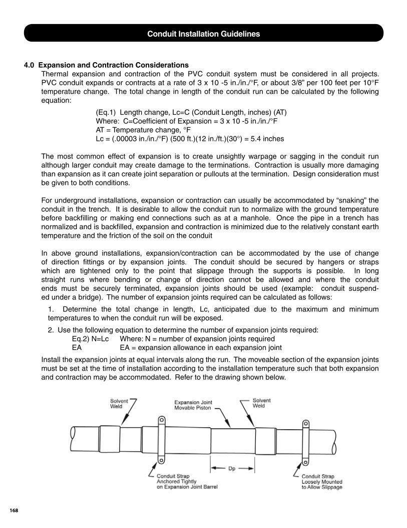
168
4.0 Expansion and Contraction Considerations Thermal expansion and contraction of the PVC conduit system must be considered in all projects. PVC conduit expands or contracts at a rate of 3 x 10 -5 in./in./°F, or about 3/8” per 100 feet per 10°F temperature change. The total change in length of the conduit run can be calculated by the following equation:
(Eq.1) Length change, Lc=C (Conduit Length, inches) (AT) Where: C=Coeffi cient of Expansion = 3 x 10 -5 in./in./°F AT = Temperature change, °F Lc = (.00003 in./in./°F) (500 ft.)(12 in./ft.)(30°) = 5.4 inches
The most common effect of expansion is to create unsightly warpage or sagging in the conduit run although larger conduit may create damage to the terminations. Contraction is usually more damaging than expansion as it can create joint separation or pullouts at the termination. Design consideration must be given to both conditions.
For underground installations, expansion or contraction can usually be accommodated by “snaking” the conduit in the trench. It is desirable to allow the conduit run to normalize with the ground temperature before backfi lling or making end connections such as at a manhole. Once the pipe in a trench has normalized and is backfi lled, expansion and contraction is minimized due to the relatively constant earth temperature and the friction of the soil on the conduit
In above ground installations, expansion/contraction can be accommodated by the use of change of direction fi ttings or by expansion joints. The conduit should be secured by hangers or straps which are tightened only to the point that slippage through the supports is possible. In long straight runs where bending or change of direction cannot be allowed and where the conduit ends must be securely terminated, expansion joints should be used (example: conduit suspend- ed under a bridge). The number of expansion joints required can be calculated as follows:
1. Determine the total change in length, Lc, anticipated due to the maximum and minimum temperatures to when the conduit run will be exposed.
2. Use the following equation to determine the number of expansion joints required: Eq.2) N=Lc Where: N = number of expansion joints required EA EA = expansion allowance in each expansion joint
Install the expansion joints at equal intervals along the run. The moveable section of the expansion joints must be set at the time of installation according to the installation temperature such that both expansion and contraction may be accommodated. Refer to the drawing shown below.
Conduit Installation Guidelines
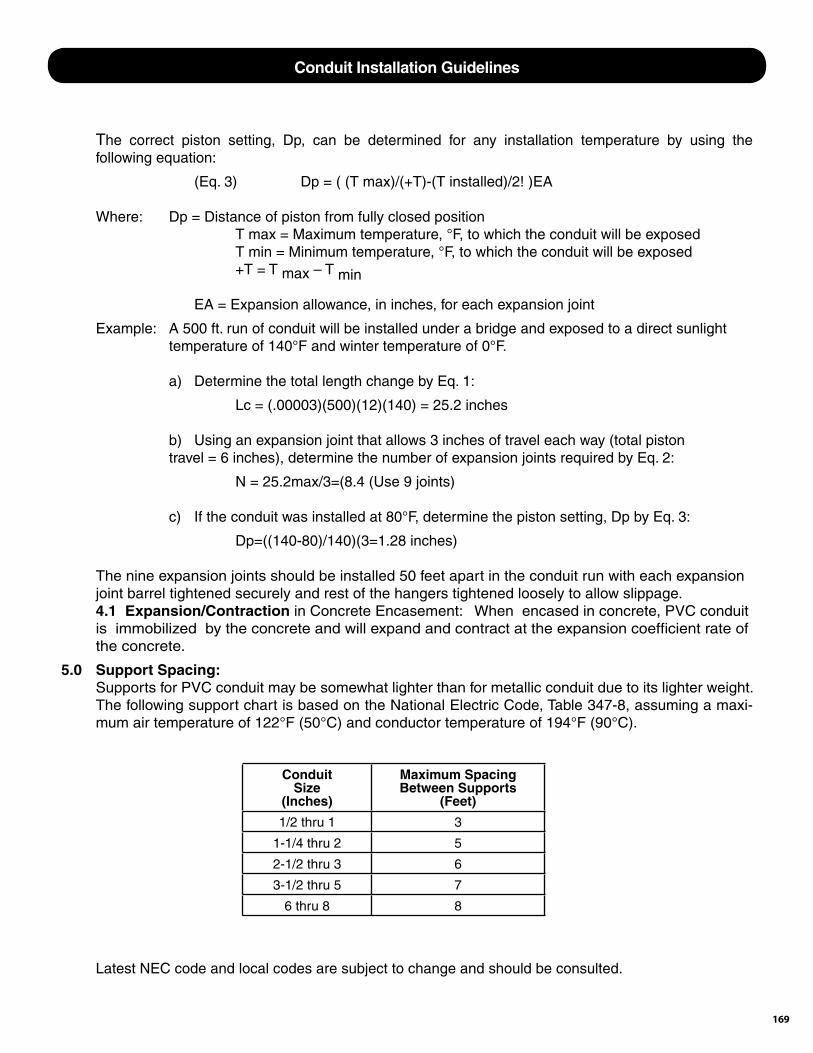
169
The correct piston setting, Dp, can be determined for any installation temperature by using the following equation:
(Eq. 3) Dp = ( (T max)/(+T)-(T installed)/2! )EA
Where: Dp = Distance of piston from fully closed position T max = Maximum temperature, °F, to which the conduit will be exposed T min = Minimum temperature, °F, to which the conduit will be exposed +T = T max – T min EA = Expansion allowance, in inches, for each expansion joint
Example: A 500 ft. run of conduit will be installed under a bridge and exposed to a direct sunlight temperature of 140°F and winter temperature of 0°F.
a) Determine the total length change by Eq. 1:
Lc = (.00003)(500)(12)(140) = 25.2 inches
b) Using an expansion joint that allows 3 inches of travel each way (total piston travel = 6 inches), determine the number of expansion joints required by Eq. 2:
N = 25.2max/3=(8.4 (Use 9 joints)
c) If the conduit was installed at 80°F, determine the piston setting, Dp by Eq. 3:
Dp=((140-80)/140)(3=1.28 inches)
The nine expansion joints should be installed 50 feet apart in the conduit run with each expansion joint barrel tightened securely and rest of the hangers tightened loosely to allow slippage. 4.1 Expansion/Contraction in Concrete Encasement: When encased in concrete, PVC conduit is immobilized by the concrete and will expand and contract at the expansion coeffi cient rate of the concrete.
5.0 Support Spacing: Supports for PVC conduit may be somewhat lighter than for metallic conduit due to its lighter weight. The following support chart is based on the National Electric Code, Table 347-8, assuming a maxi- mum air temperature of 122°F (50°C) and conductor temperature of 194°F (90°C).
Latest NEC code and local codes are subject to change and should be consulted.
ConduitSize
(Inches)
Maximum Spacing Between Supports
(Feet)
1/2 thru 1 3
1-1/4 thru 2 5
2-1/2 thru 3 6
3-1/2 thru 5 7
6 thru 8 8
Conduit Installation Guidelines
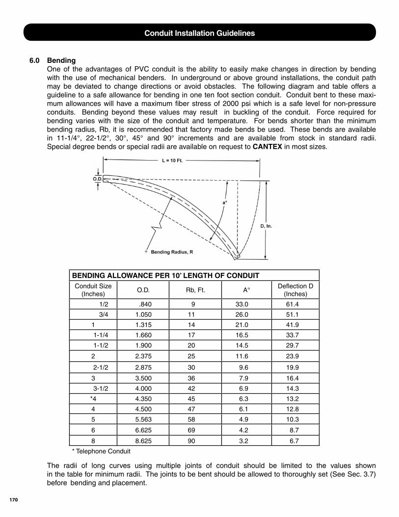
170
6.0 Bending One of the advantages of PVC conduit is the ability to easily make changes in direction by bending with the use of mechanical benders. In underground or above ground installations, the conduit path may be deviated to change directions or avoid obstacles. The following diagram and table offers a guideline to a safe allowance for bending in one ten foot section conduit. Conduit bent to these maxi- mum allowances will have a maximum fi ber stress of 2000 psi which is a safe level for non-pressure conduits. Bending beyond these values may result in buckling of the conduit. Force required for bending varies with the size of the conduit and temperature. For bends shorter than the minimum bending radius, Rb, it is recommended that factory made bends be used. These bends are available in 11-1/4°, 22-1/2°, 30°, 45° and 90° increments and are available from stock in standard radii. Special degree bends or special radii are available on request to CANTEX in most sizes.
The radii of long curves using multiple joints of conduit should be limited to the values shown in the table for minimum radii. The joints to be bent should be allowed to thoroughly set (See Sec. 3.7) before bending and placement.
BENDING ALLOWANCE PER 10’ LENGTH OF CONDUITConduit Size
(Inches)O.D. Rb, Ft. A°
Defl ection D(Inches)
1/2 .840 9 33.0 61.4
3/4 1.050 11 26.0 51.1
1 1.315 14 21.0 41.9
1-1/4 1.660 17 16.5 33.7
1-1/2 1.900 20 14.5 29.7
2 2.375 25 11.6 23.9
2-1/2 2.875 30 9.6 19.9
3 3.500 36 7.9 16.4
3-1/2 4.000 42 6.9 14.3
*4 4.350 45 6.3 13.2
4 4.500 47 6.1 12.8
5 5.563 58 4.9 10.3
6 6.625 69 4.2 8.7
8 8.625 90 3.2 6.7
* Telephone Conduit
Conduit Installation Guidelines

171
7.0 Direct Burial 7.1 Trench Width: Trench width at the ground level may vary depending on soil types, equipment used, position of surface structures, etc. Where compacting of the initial backfi ll is required, the trench should be a minimum of 5 pipe diameters. In very wide trenches, sub-ditching should be considered to provide maximum side support for the conduit. Shoring or trench boxes should be used for workman protection in loose soil or very deep trenches. 7.2 Trench Bottom: The trench bottom should be constructed to provide a fi rm, stable and uniform support for the conduit for the full lengths of the conduit. Unless specifi ed, line and grade is not required provided that the conduit will conform to the trench bottom and bending does not exceed the values given in Sec. 3.7. Large rocks and boulders, frozen lumps of soil, large lumps of clay, etc. should be removed before the conduit is installed. Rocky or uneven trench bottoms should be bedded with loose backfi ll or sand to provide a soft, even cushion for the conduit. 7.3 Initial Backfi ll: Initial backfi ll should be dry and free fl owing and contain rock not to exceed 1” in. diameter. Initial backfi ll should be applied in light layers of 3” to 6” and spread uniformly. Tamping should be done layer by layer of initial backfi ll up to the springline of the conduit. In multiple conduit installations the initial backfi ll should be worked carefully between the ducts and under the haunches. Tamping should be done between the edges of the ditch over the springline of the conduit, but no tamping should be done over the top of the conduit. Initial backfi ll should be placed loosely over the top of the conduit to a depth of 6”. All compaction by either tamping or fl ooding should be completed before the fi nal backfi ll if placed. 7.4 Final Backfi ll: After placement and compaction of conduit embedded materials, the balance of backfi ll materials may be machine placed and should contain no large rocks or stones, frozen material or other debris. Proper compaction procedures should be exercised to provide required soil densities.8.0 Concrete Encasement: 8.1 Tie and fasten all conduit to prevent fl oating. If concrete is required in the trench bottom, allow at least 2” freeboard between conduit and tie down equipment. 8.2 Spacers, if used, should be spaced at the intervals shown below or less.
A 1” minimum spacing should be allowed for all conduit and a concrete mix using pea gravel should be used for encasement. If complete encasement is required at areas requiring bends in making freeway or water crossings, use a 2” minimum spacing. 8.3 Coverage: Minimum concrete coverage should be 2” on top, bottom and sides of conduit. Firm soil conditions may eliminate need for concrete at the trench bottom. 8.4 Backfi lling: Backfi lling can be done as soon as the concrete has cured to withstand the weight of a man. 8.5 Temperature Considerations: The temperature rise of the concrete as it cures may cause some expansion of the conduit. Concrete should be poured from the center of the run toward each free end or from one tie-in point toward the free end of the conduit. Make permanent terminal tie-ins after the temperature has normalized.
Conduit SizeSize
(Inches)
Spacing(Feet)
½ thru 2 4 thru 6
3 thru 3 ½ 5 thru 8
4 thru 8 6 thru 10
Conduit Installation Guidelines
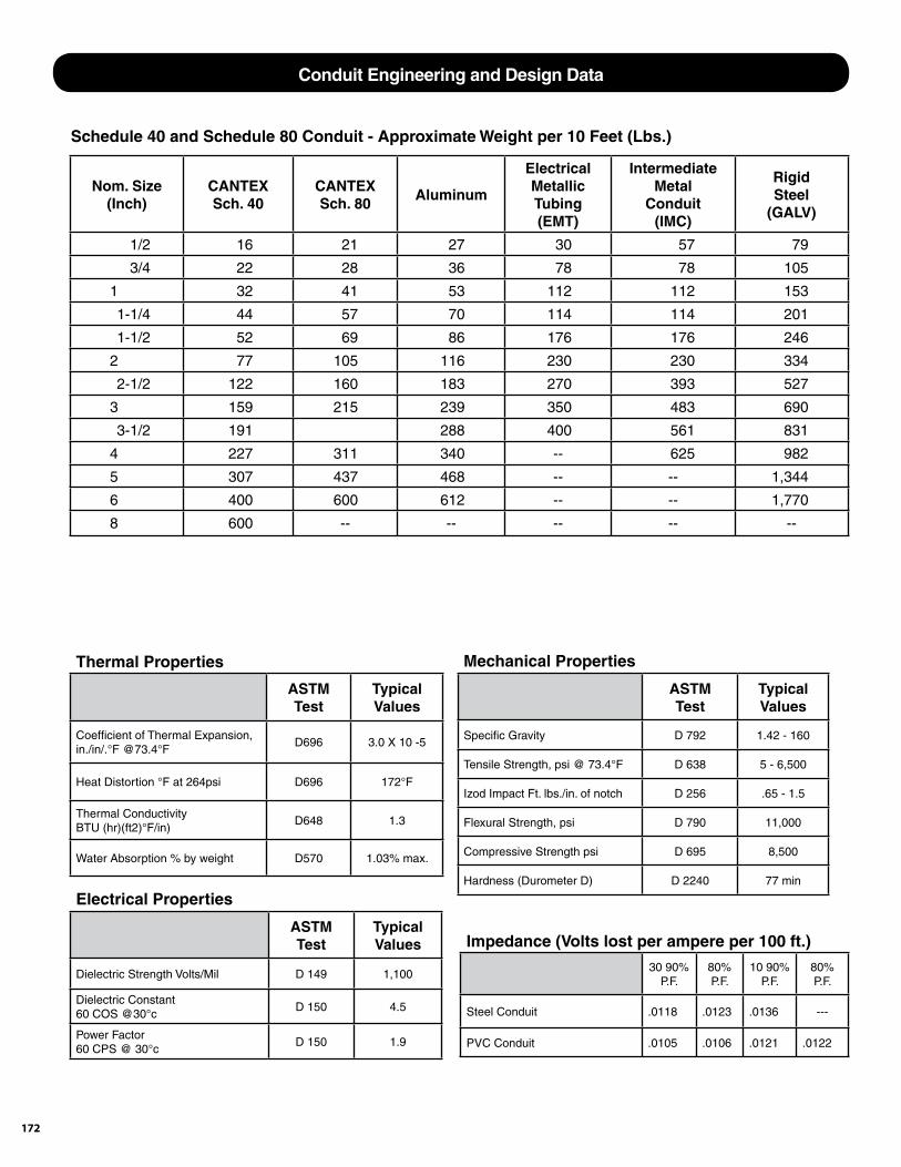
172
Thermal Properties
ASTM Test
Typical Values
Coeffi cient of Thermal Expansion, in./in/.°F @73.4°F
D696 3.0 X 10 -5
Heat Distortion °F at 264psi D696 172°F
Thermal Conductivity BTU (hr)(ft2)°F/in)
D648 1.3
Water Absorption % by weight D570 1.03% max.
Mechanical Properties
ASTM Test
Typical Values
Specifi c Gravity D 792 1.42 - 160
Tensile Strength, psi @ 73.4°F D 638 5 - 6,500
Izod Impact Ft. lbs./in. of notch D 256 .65 - 1.5
Flexural Strength, psi D 790 11,000
Compressive Strength psi D 695 8,500
Hardness (Durometer D) D 2240 77 min
Electrical Properties
ASTM Test
Typical Values
Dielectric Strength Volts/Mil D 149 1,100
Dielectric Constant 60 COS @30°c
D 150 4.5
Power Factor 60 CPS @ 30°c
D 150 1.9
Impedance (Volts lost per ampere per 100 ft.)
30 90% P.F.
80% P.F.
10 90% P.F.
80% P.F.
Steel Conduit .0118 .0123 .0136 ---
PVC Conduit .0105 .0106 .0121 .0122
Nom. Size(Inch)
CANTEXSch. 40
CANTEXSch. 80
Aluminum
ElectricalMetallicTubing(EMT)
IntermediateMetal
Conduit(IMC)
RigidSteel
(GALV)
1/2 16 21 27 30 57 79
3/4 22 28 36 78 78 105
1 32 41 53 112 112 153
1-1/4 44 57 70 114 114 201
1-1/2 52 69 86 176 176 246
2 77 105 116 230 230 334
2-1/2 122 160 183 270 393 527
3 159 215 239 350 483 690
3-1/2 191 288 400 561 831
4 227 311 340 -- 625 982
5 307 437 468 -- -- 1,344
6 400 600 612 -- -- 1,770
8 600 -- -- -- -- --
Schedule 40 and Schedule 80 Conduit - Approximate Weight per 10 Feet (Lbs.)
Conduit Engineering and Design Data
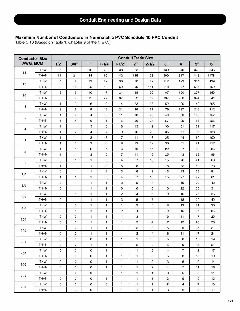
173
Conductor Size AWG, MCM
Conduit Trade Size
1/2” 3/4” 1” 1-1/4” 1-1/2” 2” 2-1/2” 3” 4” 5” 6”
14THW 5 9 16 28 38 63 90 139 240 378 546
THHN 11 21 34 60 82 135 193 299 517 815 1178
12THW 4 8 12 22 30 50 72 112 193 304 439
THHN 8 15 25 43 59 99 141 218 377 594 859
10THW 3 6 10 17 24 39 56 87 150 237 343
THHN 5 9 15 27 37 62 89 137 238 374 541
8THW 1 3 6 10 14 23 33 52 90 142 205
THHN 3 5 9 16 21 36 51 79 137 216 312
6THW 1 2 4 8 11 18 26 40 69 109 157
THHN 1 4 6 11 15 26 37 57 99 156 225
4THW 1 1 3 6 8 13 19 30 51 81 117
THHN 1 2 4 7 9 16 22 35 61 96 138
3THW 1 1 3 5 7 11 16 25 44 69 100
THHN 1 1 3 6 8 13 19 30 51 81 117
2THW 1 1 2 4 6 10 14 22 37 59 85
THHN 1 1 3 5 7 11 16 25 43 68 98
1THW 0 1 1 3 4 7 10 15 26 41 60
THHN 1 1 1 3 5 8 12 18 32 50 73
1/0THW 0 1 1 2 3 6 8 13 22 35 51
THHN 1 1 1 3 4 7 10 15 27 42 61
2/0THW 0 1 1 1 3 5 7 11 19 30 43
THHN 0 1 1 2 3 6 8 13 22 35 51
3/0THW 0 1 1 1 2 4 6 9 16 25 36
THHN 0 1 1 1 3 5 7 11 18 29 42
4/0THW 0 0 1 1 1 3 5 8 13 21 30
THHN 0 1 1 1 2 4 6 9 15 24 35
250THW 0 0 1 1 1 3 4 6 11 17 25
THHN 0 0 1 1 1 3 4 7 12 20 28
300THW 0 0 1 1 1 2 3 5 9 15 21
THHN 0 0 1 1 1 3 4 6 11 17 24
350THW 0 0 0 1 1 1 35 5 8 13 19
THHN 0 0 1 1 1 2 3 5 9 15 21
400THW 0 0 0 1 1 1 3 4 7 12 17
THHN 0 0 0 1 1 1 3 5 8 13 19
500THW 0 0 0 1 1 1 2 3 6 10 14
THHN 0 0 0 1 1 1 2 4 7 11 16
600THW 0 0 0 0 1 1 1 3 5 8 11
THHN 0 0 0 1 1 1 1 3 5 9 13
700THW 0 0 0 0 1 1 1 2 4 7 10
THHN 0 0 0 0 1 1 1 3 5 8 11
Maximum Number of Conductors in Nonmetallic PVC Schedule 40 PVC ConduitTable C.10 (Based on Table 1, Chapter 9 of the N.E.C.)
Conduit Engineering and Design Data
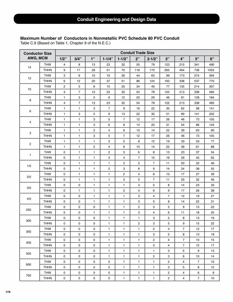
174
Conductor Size AWG, MCM
Conduit Trade Size
1/2” 3/4” 1” 1-1/4” 1-1/2” 2” 2-1/2” 3” 4” 5” 6”
14THW 4 8 13 23 32 55 79 123 215 341 490
THHN 9 17 28 51 70 118 170 265 464 736 1055
12THW 3 6 10 19 26 44 63 99 173 274 394
THHN 6 12 20 37 51 86 124 193 338 537 770
10THW 2 5 8 15 20 34 49 77 135 214 307
THHN 4 7 13 23 32 54 78 122 213 338 485
8THW 1 3 5 9 12 20 29 46 81 128 184
THHN 4 7 13 23 32 54 78 122 213 338 485
6THW 1 1 3 7 9 16 22 35 62 98 141
THHN 1 3 5 9 13 22 32 51 89 141 202
4THW 1 1 3 5 7 12 17 26 46 73 105
THHN 1 1 3 6 8 14 20 31 54 86 124
3THW 1 1 2 4 6 10 14 22 39 63 90
THHN 1 1 3 5 7 12 17 26 46 73 105
2THW 1 1 1 3 5 8 12 19 33 53 77
THHN 1 1 2 4 6 10 14 22 39 61 88
1THW 0 1 1 2 3 6 8 13 23 37 54
THHN 0 1 1 3 4 7 10 16 29 45 65
1/0THW 0 1 1 1 3 5 7 11 20 32 46
THHN 0 1 1 2 3 6 9 14 24 38 55
2/0THW 0 1 1 1 2 4 6 10 17 27 39
THHN 0 1 1 1 3 5 7 11 20 32 46
3/0THW 0 0 1 1 1 3 5 8 14 23 33
THHN 0 1 1 1 2 4 6 9 17 26 38
4/0THW 0 0 1 1 1 3 4 7 12 19 27
THHN 0 0 1 1 1 3 5 8 14 22 31
250THW 0 0 0 1 1 2 3 5 9 15 22
THHN 0 0 1 1 1 3 4 6 11 18 25
300THW 0 0 0 1 1 1 3 5 8 13 19
THHN 0 0 0 1 1 2 3 5 9 15 22
350THW 0 0 0 1 1 1 2 4 7 12 17
THHN 0 0 0 1 1 1 3 5 8 13 19
400THW 0 0 0 1 1 1 2 4 7 10 15
THHN 0 0 0 1 1 1 3 4 7 12 17
500THW 0 0 0 1 1 1 1 3 5 9 13
THHN 0 0 0 1 1 1 2 3 6 10 14
600THW 0 0 0 0 1 1 1 2 4 7 10
THHN 0 0 0 0 1 1 1 3 5 8 12
700THW 0 0 0 0 1 1 1 2 4 6 9
THHN 0 0 0 0 1 1 1 2 4 7 10
Maximum Number of Conductors in Nonmetallic PVC Schedule 80 PVC ConduitTable C.9 (Based on Table 1, Chapter 9 of the N.E.C.)
Conduit Engineering and Design Data
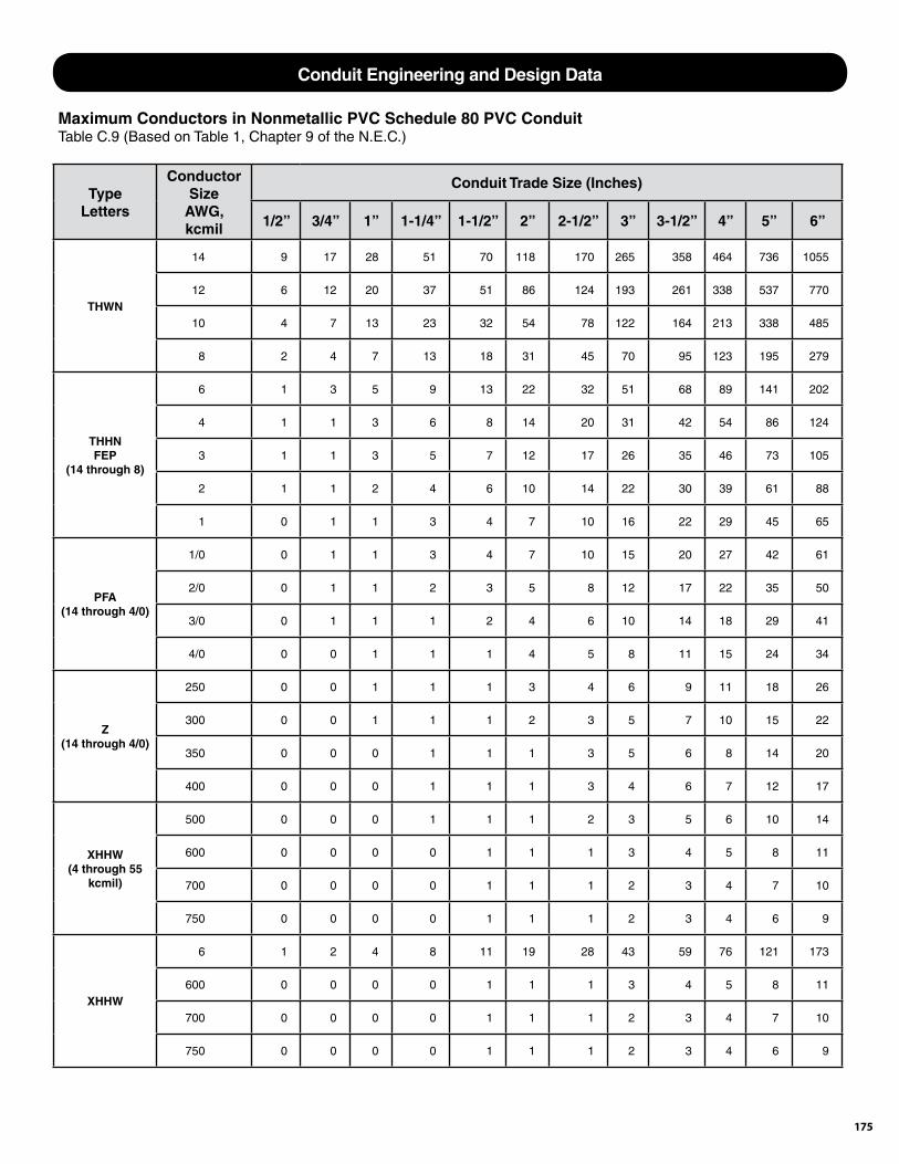
175
Type Letters
Conductor Size
AWG, kcmil
Conduit Trade Size (Inches)
1/2” 3/4” 1” 1-1/4” 1-1/2” 2” 2-1/2” 3” 3-1/2” 4” 5” 6”
THWN
14 9 17 28 51 70 118 170 265 358 464 736 1055
12 6 12 20 37 51 86 124 193 261 338 537 770
10 4 7 13 23 32 54 78 122 164 213 338 485
8 2 4 7 13 18 31 45 70 95 123 195 279
THHN FEP
(14 through 8)
6 1 3 5 9 13 22 32 51 68 89 141 202
4 1 1 3 6 8 14 20 31 42 54 86 124
3 1 1 3 5 7 12 17 26 35 46 73 105
2 1 1 2 4 6 10 14 22 30 39 61 88
1 0 1 1 3 4 7 10 16 22 29 45 65
PFA (14 through 4/0)
1/0 0 1 1 3 4 7 10 15 20 27 42 61
2/0 0 1 1 2 3 5 8 12 17 22 35 50
3/0 0 1 1 1 2 4 6 10 14 18 29 41
4/0 0 0 1 1 1 4 5 8 11 15 24 34
Z (14 through 4/0)
250 0 0 1 1 1 3 4 6 9 11 18 26
300 0 0 1 1 1 2 3 5 7 10 15 22
350 0 0 0 1 1 1 3 5 6 8 14 20
400 0 0 0 1 1 1 3 4 6 7 12 17
XHHW (4 through 55
kcmil)
500 0 0 0 1 1 1 2 3 5 6 10 14
600 0 0 0 0 1 1 1 3 4 5 8 11
700 0 0 0 0 1 1 1 2 3 4 7 10
750 0 0 0 0 1 1 1 2 3 4 6 9
XHHW
6 1 2 4 8 11 19 28 43 59 76 121 173
600 0 0 0 0 1 1 1 3 4 5 8 11
700 0 0 0 0 1 1 1 2 3 4 7 10
750 0 0 0 0 1 1 1 2 3 4 6 9
Maximum Conductors in Nonmetallic PVC Schedule 80 PVC ConduitTable C.9 (Based on Table 1, Chapter 9 of the N.E.C.)
Conduit Engineering and Design Data
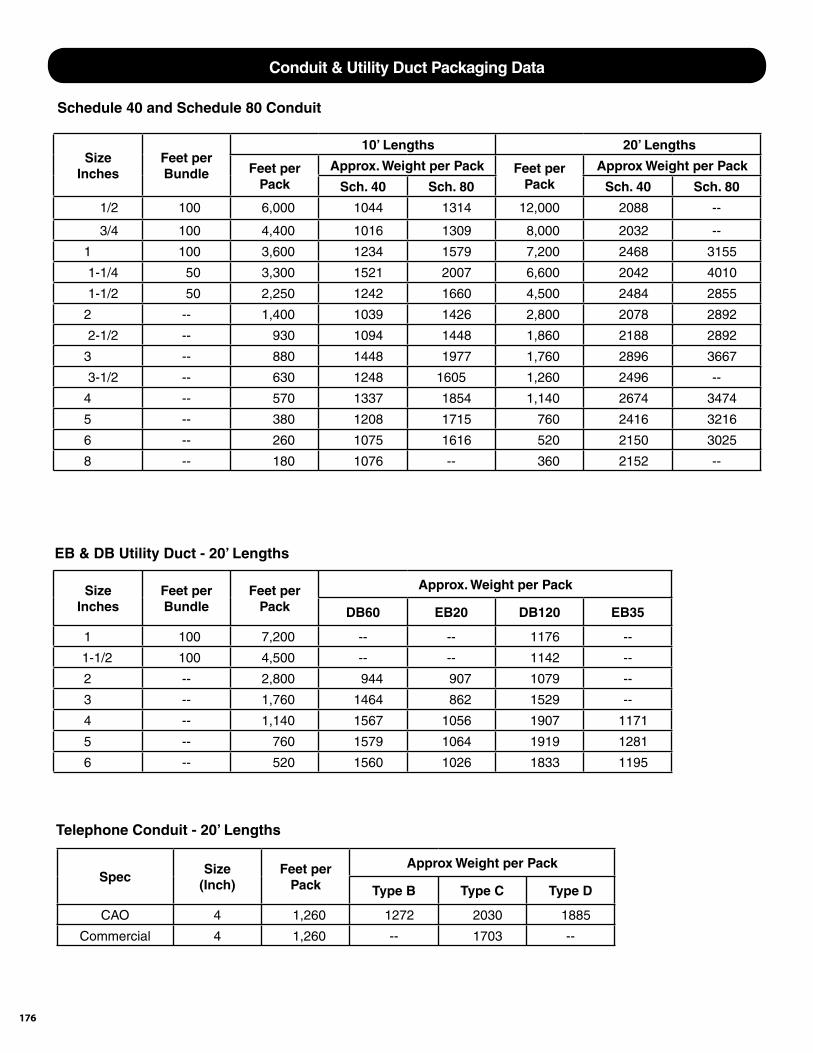
176
SizeInches
Feet perBundle
10’ Lengths 20’ Lengths
Feet perPack
Approx. Weight per Pack Feet per Pack
Approx Weight per Pack
Sch. 40 Sch. 80 Sch. 40 Sch. 80
1/2 100 6,000 1044 1314 12,000 2088 --
3/4 100 4,400 1016 1309 8,000 2032 --
1 100 3,600 1234 1579 7,200 2468 3155
1-1/4 50 3,300 1521 2007 6,600 2042 4010
1-1/2 50 2,250 1242 1660 4,500 2484 2855
2 -- 1,400 1039 1426 2,800 2078 2892
2-1/2 -- 930 1094 1448 1,860 2188 2892
3 -- 880 1448 1977 1,760 2896 3667
3-1/2 -- 630 1248 1605 1,260 2496 --
4 -- 570 1337 1854 1,140 2674 3474
5 -- 380 1208 1715 760 2416 3216
6 -- 260 1075 1616 520 2150 3025
8 -- 180 1076 -- 360 2152 --
Schedule 40 and Schedule 80 Conduit
SizeInches
Feet perBundle
Feet perPack
Approx. Weight per Pack
DB60 EB20 DB120 EB35
1 100 7,200 -- -- 1176 --
1-1/2 100 4,500 -- -- 1142 --
2 -- 2,800 944 907 1079 --
3 -- 1,760 1464 862 1529 --
4 -- 1,140 1567 1056 1907 1171
5 -- 760 1579 1064 1919 1281
6 -- 520 1560 1026 1833 1195
EB & DB Utility Duct - 20’ Lengths
SpecSize
(Inch)Feet per
Pack
Approx Weight per Pack
Type B Type C Type D
CAO 4 1,260 1272 2030 1885
Commercial 4 1,260 -- 1703 --
Telephone Conduit - 20’ Lengths
Conduit & Utility Duct Packaging Data
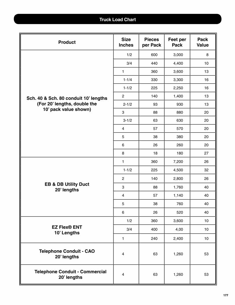
177
ProductSize
InchesPieces
per PackFeet per
PackPack Value
Sch. 40 & Sch. 80 conduit 10’ lengths(For 20’ lengths, double the
10’ pack value shown)
1/2 600 3,000 8
3/4 440 4,400 10
1 360 3,600 13
1-1/4 330 3,300 16
1-1/2 225 2,250 16
2 140 1,400 13
2-1/2 93 930 13
3 88 880 20
3-1/2 63 630 20
4 57 570 20
5 38 380 20
6 26 260 20
8 18 180 27
EB & DB Utility Duct20’ lengths
1 360 7,200 26
1-1/2 225 4,500 32
2 140 2,800 26
3 88 1,760 40
4 57 1,140 40
5 38 760 40
6 26 520 40
EZ Flex® ENT10’ Lengths
1/2 360 3,600 10
3/4 400 4,00 10
1 240 2,400 10
Telephone Conduit - CAO20’ lengths
4 63 1,260 53
Telephone Conduit - Commercial20’ lengths
4 63 1,260 53
Truck Load Chart
Limited WarrantyThe Seller, CANTEX INC., warrants its PVC plastic pipe, conduit, fi ttings, accessories, residential electrical boxes and solvents against defective workmanship and material for a period of one year from date of applicable invoice. Seller’s liability hereunder, either for breach of warranty or for negligence, is expressly limited, at Seller’s option, to: A) Replacement at the agreed point of delivery, at no cost to the Purchaser, of any product found by the Seller to be defective of found not to conform to the applicable industry manufacturing standards, or B) to refund or credit to the Purchaser of the purchase price of such products, provided the Seller is notifi ed immediately upon the discovery of any claimed defect and that representative samples of the allegedly defective product are returned, transportation prepaid, to Seller, F.O.B. shipping point, at Seller’s request. No claim under this Limited Warranty will be considered until the product and representative samplings thereof have been examined by Seller.The above warranty constitutes the entire liability of Seller. Seller shall not be liable for any incidental consequential damages directly or indirectly arising or resulting from the sale, transportation, handling, installation or use of the products sold, nor for product loss, re-installation or labor cost.
THIS WARRANTY IS EXPRESSLY IN LIEU OF ANY OTHER WARRANTIES,EXPRESSED OR IMPLIED, INCLUDING ANY IMPLIED WARRANTY OF
MERCHANTABILITY OR FITNESS FOR ANY PARTICULAR PURPOSE, ANDOF ANY OTHER OBLIGATION OR LIABILITY ON THE PART OF THE SELLER.
Situations that void this Limited Warranty: 1. Excessive temperature combination during test of operation. 2. Use of the product under conditions for which the product was not designed 3. Failure to adhere to Seller’s General Instruction Sheets concerning the proper handling, installation and testing of the product. General Instruction sheets are available on request: Call 817-215-7000. 4. Use of non-suitable solvent cement. Suitable solvent cement shall be cement made in accordance with ASTM D 2564 and of the proper grade (viscosity) for the size of pipe being joined. CANTEX solvent cements meet these requirements.
940-325-3344 · 2101 NE 1st Street 330-995-3665m · 101 Gandy RoadMineral Wells, Texas 76067 Auburndale, Florida 33823
330-995-3665 · 11444 Chamberlain Rd. #1 928-681-3301 · 4045 Bonanza DriveAurora, Ohio 44202 Kingman, Arizona 86401
®
817-215-7000 · 301 Commerce Ste. 2700Fort Worth, Texas 76102
178

179
Authorized Distributor Policy
1. BUYER’S ACCEPTANCE No waiver, alteration or modifi cation of these conditions will be binding unless in writing signed by an authorized employee of CANTEX INC.
2. PAYMENT TERMS
All prices are F.O.B. shipping point with freight costs being collect, prepaid or allowed and do not include local, state or Federal taxes. Taxes are for the account of Buyer. Payment terms appear on the face of Buyers invoice. All orders are subject to credit approval.
3. DELINQUENCY FEEDS If any invoice or part thereof is not paid within 30 days of date of invoice, CANTEX will impose as Delinquency Fees a charge of one (1%) percent per month or the maximum applicable legal amount upon any overdue amount to offset CANTEX’s anticipated damages including collection and accouting costs. Buyer agrees that the law of the State of Buyer’s location will govern the construction and validity of this Contract and all other legal aspects of this sale.
4. CANCELLATION Buyer may cancel prior to shipment subject to Delinquency Fees of the cost of labor, overhead and materials used plus ten (10%) percent of the sales price. Special orders may not be cancelled.
5. RETURNS No material may be returned for credit without the Seller’s written consent.
6. SHIPMENT / DELIVERY CANTEX will ship common carrier. Errors for breakage of product delivered by common carrier are Buyer’s responsibility. Buyer is responsible for prompt unloading of trucks and/or freight cars. If delivery of products is delayed by Buyer more than 60 days, Buyer will pay CANTEX eighty (80%) percent of total cost of products.
7. INSTALLATION Supervision of installation not included unless specifi cally requested. CANTEX will not be responsible for any delay in performance due to acts of God, war, riots, embargoes, acts of civil or military authorities, fi res, fl oods, accidents, quarantine restrictions, supplier conditions, strikes, differences with workmen, cessation of plant operations, delays in transportation, nuclear incident, shortage of cars, fuel, labor or materials, or any cause beyond the reasonable control of CANTEX.
9. COMPLIANCE CANTEX states its intentions to comply with all Federal laws applicable to CANTEX’s performance.
Terms and Conditions of Sale are available for download. Click the link on our homepage.
www.cantexinc.com
180
Authorized Distributor Policy
Returned Good Policy 1. Stock Inventory:
A) Permission for such return of good must fi rst be obtained from CANTEX in writing. Such request must show CANTEX invoice number, date, quantity of items and CANTEX part number.
B) Material to be returned must be new, unused, properly packaged and in resalable condition. No credit will be issued for open or partially used packages.
C) Request for return must be processed within 6 months from the date of purchase.
D) The RGA (Returned Goods Authorization) will expire 30 days from date of issue. If the material is received after that date, terms of the return must be renegotiated.
E) Material must be received at the location indicated on the RGA or it will become null and void.
F) Restocking charge is 25%.
G) The distributor will prepay freight cost to return the product and the outbound freight will be deducted from the credit issued.
Our Philosophy It is the intent of CANTEX Inc. to sell our PVC electrical conduit, accessory products and switch and outlet boxes primarily through distributors. We believe the distributors play a necessary and vital role in our company and that it is to our mutual advantage that CANTEX offers to its authorized distributors the most complete program possible.
CANTEX’s objective is to select and establish recognized electrical distributors to thoroughly cover each geographical area and each market segment that CANTEX serves.
Our goal is to be a signifi cant and increasing profi t contributor to each of our authorized CANTEX distributors.
In GeneralWith the philosophy stated, CANTEX carries out the following steps to insure the competitiveness and full profi tability of each of our authorized distributors.
1. CANTEX is constantly adding to its line of electrical conduit and accessories.
2. Our products are manufactured to the highest quality standards and meet or exceed all applicable standards.
3. CANTEX offers the following benefi ts to its distributors:
A. The best delivery in the industry.
B. Referred business.
C. Assortment privileges in total product line for quantity discount.
D. Fair pricing.
E. We will drop-ship prepaid orders at no extra charge.
4. CANTEX aids the sales efforts of our authorized distributors in the following manner:
A. Sales leads derived from national advertising and trade shows.
B. Conducting sales meetings for our distributors.
C. Have an in-place factory direct sales/service staff to assist you in your sales effort.
D. Literature and samples for promotional purposes.
5. We expect an authorized CANTEX distributor to:
A. Maintain products in inventory.
B. Use best efforts and due diligence in the promotion and sale of CANTEX products.
C. Maintain their account on a current basis.
6. CANTEX reserves the right to quote special drop-shipments only through those distributors who maintain an acceptable inventory of CANTEX products.

181

182
301 Commerce Suite 2700Fort Worth, Texas 76102Ph: (817) 215-7000Fax: (817) 215-7001
®