Embed Size (px)
Citation preview

By: Karen T. Fuentes, P.E.
Sr. Principal Engineer
Pinhole leaks in tubing occur frequently and for a variety
of reasons. Here are a few examples of conditions
leading to pin hole leaks in tubes.
Under Deposit Corrosion
As the name implies, under deposit corrosion results
when deposits are laid down on either the internal or
external surface of a water-touched tube. Once a
deposit is laid down on the tube surface the “chemistry”
of the environment under the deposit can become
significantly different to the general tube environment.
It is this concentrating effect under the deposit that
leads to pitting. The corrosion can be caused by a
number of chemical species including caustic (caustic
gouging), oxygen (oxygen pitting), and phosphate
(phosphate gouging or acid phosphate corrosion). In
water-containing piping and tubing in ambient or near
ambient temperatures, microbiological deposits can also
cause corrosion.
External deposits tend to collect in dead
flow areas such as near baffle plates and
tube sheets. Internal deposits tend to
collect on the bottom of horizontal
tubes, in the corners of the rifling of
internally rifled tubes, at the liquid line in tubes that are
only partially filled, in flow disruption areas such as
bends, or areas of high heat flux. (Continued on page 2)
the Conduit A quarterly publication from
M&M Engineering Associates, Inc.
5 Chemical Treatments for Closed
Loop Systems
9 Upcoming Events
Workshop—Fall Edition 10
INSIDE THIS ISSUE: Vol. 15, No. 1
PIN HOLE LEAKS IN TUBING
Tube wall
Internal
Deposit
Figure 1. A small leak shown on the internal surface in
the tube wall (arrow).
Figure 2. A cross section of tube shown in the area of
the leak.
2
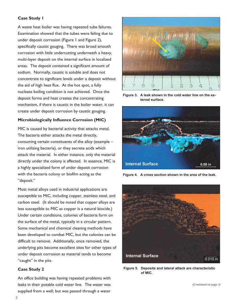
Case Study 1
A waste heat boiler was having repeated tube failures.
Examination showed that the tubes were failing due to
under deposit corrosion (Figure 1 and Figure 2),
specifically caustic gouging. There was broad smooth
corrosion with little undercutting underneath a heavy,
multi-layer deposit on the internal surface in localized
areas. The deposit contained a significant amount of
sodium. Normally, caustic is soluble and does not
concentrate to significant levels under a deposit without
the aid of high heat flux. At the hot spot, a fully
nucleate boiling condition is not achieved. Once the
deposit forms and heat creates the concentrating
mechanism, if there is caustic in the boiler water, it can
create under deposit corrosion by caustic gouging.
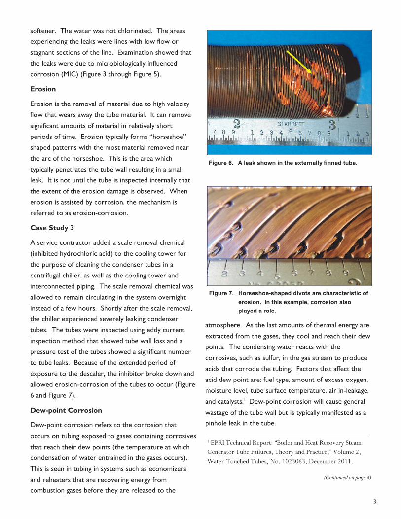
Microbiologically Influence Corrosion (MIC)
MIC is caused by bacterial activity that attacks metal.
The bacteria either attacks the metal directly,
consuming certain constituents of the alloy (example –
iron utilizing bacteria), or they secrete acids which
attack the material. In either instance, only the material
directly under the colony is affected. In essence, MIC is
a highly specialized form of under deposit corrosion
with the bacteria colony or biofilm acting as the
“deposit.”
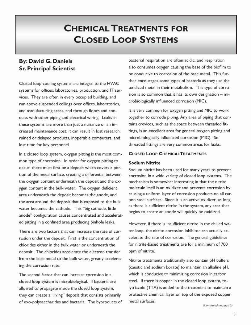
Most metal alloys used in industrial applications are
susceptible to MIC, including copper, stainless steel, and
carbon steel. (It should be noted that copper alloys are
less susceptible to MIC as copper is a natural biocide.)
Under certain conditions, colonies of bacteria form on
the surface of the metal, typically in a circular pattern.
Some mechanical and chemical cleaning methods have
been developed to combat MIC, but the colonies can be
difficult to remove. Additionally, once removed, the
underlying pits become excellent sites for other types of
under deposit corrosion as material tends to become
“caught” in the pits.
Case Study 2
An office building was having repeated problems with
leaks in their potable cold water line. The water was
supplied from a well, but was passed through a water
(Continued on page 3)
Figure 3. A leak shown in the cold water line on the ex-
ternal surface.
Figure 4. A cross section shown in the area of the leak.
Figure 5. Deposits and lateral attack are characteristic
of MIC.
Internal Surface
Internal Surface
3
softener. The water was not chlorinated. The areas
experiencing the leaks were lines with low flow or
stagnant sections of the line. Examination showed that
the leaks were due to microbiologically influenced
corrosion (MIC) (Figure 3 through Figure 5).
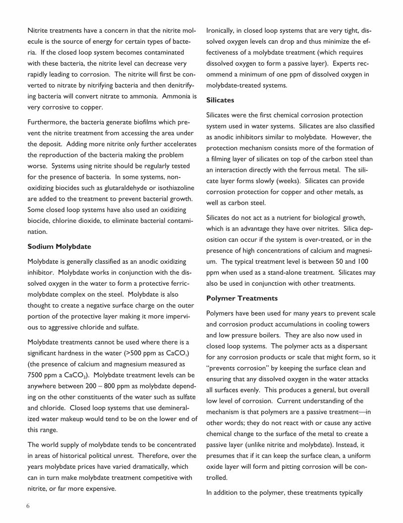
Erosion
Erosion is the removal of material due to high velocity
flow that wears away the tube material. It can remove
significant amounts of material in relatively short
periods of time. Erosion typically forms “horseshoe”
shaped patterns with the most material removed near
the arc of the horseshoe. This is the area which
typically penetrates the tube wall resulting in a small
leak. It is not until the tube is inspected internally that
the extent of the erosion damage is observed. When
erosion is assisted by corrosion, the mechanism is
referred to as erosion-corrosion.
Case Study 3
A service contractor added a scale removal chemical
(inhibited hydrochloric acid) to the cooling tower for
the purpose of cleaning the condenser tubes in a
centrifugal chiller, as well as the cooling tower and
interconnected piping. The scale removal chemical was
allowed to remain circulating in the system overnight
instead of a few hours. Shortly after the scale removal,
the chiller experienced severely leaking condenser
tubes. The tubes were inspected using eddy current
inspection method that showed tube wall loss and a
pressure test of the tubes showed a significant number
to tube leaks. Because of the extended period of
exposure to the descaler, the inhibitor broke down and
allowed erosion-corrosion of the tubes to occur (Figure
6 and Figure 7).
Dew-point Corrosion
Dew-point corrosion refers to the corrosion that
occurs on tubing exposed to gases containing corrosives
that reach their dew points (the temperature at which
condensation of water entrained in the gases occurs).
This is seen in tubing in systems such as economizers
and reheaters that are recovering energy from
combustion gases before they are released to the
atmosphere. As the last amounts of thermal energy are
extracted from the gases, they cool and reach their dew
points. The condensing water reacts with the
corrosives, such as sulfur, in the gas stream to produce
acids that corrode the tubing. Factors that affect the
acid dew point are: fuel type, amount of excess oxygen,
moisture level, tube surface temperature, air in-leakage,
and catalysts.1 Dew-point corrosion will cause general
wastage of the tube wall but is typically manifested as a
pinhole leak in the tube.
(Continued on page 4)
Figure 7. Horseshoe-shaped divots are characteristic of
erosion. In this example, corrosion also
played a role.
Figure 6. A leak shown in the externally finned tube.
1 EPRI Technical Report: “Boiler and Heat Recovery Steam
Generator Tube Failures, Theory and Practice,” Volume 2,
Water-Touched Tubes, No. 1023063, December 2011.

4
Case Study 4
A tube sample was removed for analysis after repeated
pinhole leaks were experienced in the economizer from
a coal burning, circulating fluidized bed boiler (Figure 8).
After sectioning the tube, wastage of the tube wall was
observed (Figure 9). Analysis of the external deposits
identified primarily iron and oxygen (iron oxide), with
some sulfur. A white layer of iron sulfate at the tube
deposit interface is also typical of dew-point corrosion.
White deposits were observed in the leak area.
The first temperature at which sulfuric acid condenses
depends on the partial pressures of SO3 and water
vapor, and is usually around 250°F to 300°F. Coal firing
may have a slightly lower dew point range (250°F - 285°
F) because much of the ash contains alkaline
compounds. The peak corrosion rate occurs at about
260°F. Excess oxygen is also an important factor as the
higher the oxygen level in the combustion process, the
more SO2 will be converted to SO3. By controlling
excess oxygen to a maximum of 1 to 2%, it is possible
to avoid the the formation of fully oxidized sulfur
compounds and thereby reduce fouling and tube
corrosion.
(Continued from page 3)
Now available online! Boiler Tube Failure Handbook
The handbook presents examples of common failure
mechanisms in a variety of boilers including power boilers,
recovery boilers, and heat recovery steam generators
(HRSGs). Visual examination may help the equipment
operator decide whether further metallurgical examina-
tion and root cause analysis is warranted. The only sure
way to determine a failure mechanism and root cause is a
full metallurgical examination.
Click to visit: http://mmengineering.com/boiler-tube
-failure-handbook/
Figure 9. Image shows external wastage of tube in the
leak area (bracket) viewed from the internal
surface.
Figure 8. Image shows pin hole leaks in an economizer
tube.
Contact the Author:
Karen T. Fuentes, Sr. Principal Engineer
(512) 407-3778
In Memoriam Arthur H. Tuthill, prominent chemical engineer from
Blacksburg, Virginia, died February 10, 2015, at the age
of 95. He graduated from the University of
Virginia as a chemical engineer and earned his
master's degree in metallurgy from the Carnegie
Institute of Technology. He worked in corrosion
engineering for Standard Oil, Valco Engineering, and
International Nickel, and as a corrosion consultant for
Tuthill Associates. Art also worked with M&M
Engineering for many years. A prominent and special-
ized corrosion engineer, he authored more than 100
technical papers and received numerous awards in his
field. His contributions to the fields of metallurgy and
corrosion will assist us for years to come; he will be
missed.
5
By: David G. Daniels
Sr. Principal Scientist
Closed loop cooling systems are integral to the HVAC
systems for offices, laboratories, production, and IT ser-
vices. They are often in every occupied building, and
run above suspended ceilings over offices, laboratories,
and manufacturing areas, and through floors and con-
duits with other piping and electrical wiring. Leaks in
these systems are more than just a nuisance or an in-
creased maintenance cost; it can result in lost research,
ruined or delayed products, inoperable computers, and
lost time for key personnel.
In a closed loop system, oxygen pitting is the most com-
mon type of corrosion. In order for oxygen pitting to
occur, there must first be a deposit which covers a por-
tion of the metal surface, creating a differential between
the oxygen content underneath the deposit and the ox-
ygen content in the bulk water. The oxygen deficient
area underneath the deposit becomes the anode, and
the area around the deposit that is exposed to the bulk
water becomes the cathode. This “big cathode, little
anode” configuration causes concentrated and accelerat-
ed pitting in a confined area producing pinhole leaks.
There are two factors that can increase the rate of cor-
rosion under the deposit. First is the concentration of
chlorides either in the bulk water or underneath the
deposit. The chlorides accelerate the electron transfer
from the base metal to the bulk water, greatly accelerat-
ing the corrosion rate.
The second factor that can increase corrosion in a
closed loop system is microbiological. If bacteria are
allowed to propagate inside the closed loop system,
they can create a “living” deposit that consists primarily
of exo-polysaccharides and bacteria. The byproducts of
bacterial respiration are often acidic, and respiration
also consumes oxygen causing the base of the biofilm to
be conducive to corrosion of the base metal. This fur-
ther encourages some types of bacteria as they use the
oxidized metal in their metabolism. This type of corro-
sion is so common that it has its own designation – mi-
crobiologically influenced corrosion (MIC).
It is very common for oxygen pitting and MIC to work
together to corrode piping. Any area of piping that con-
tains crevices, such as the space between threaded fit-
tings, is an excellent area for general oxygen pitting and
microbiologically influenced corrosion (MIC). So
threaded fittings are very common areas for leaks.
CLOSED LOOP CHEMICALTREATMENTS
Sodium Nitrite
Sodium nitrite has been used for many years to prevent
corrosion in a wide variety of closed loop systems. The
mechanism is somewhat interesting in that the nitrite
molecule itself is an oxidizer and prevents corrosion by
causing a uniform layer of corrosion products on all car-
bon steel surfaces. Since it is an active oxidizer, as long
as there is sufficient nitrite in the system, any area that
begins to create an anode will quickly be oxidized.
However, if there is insufficient nitrite in the chilled wa-
ter loop, the nitrite corrosion inhibitor can actually ac-
celerate the rate of corrosion. The general guidelines
for nitrite-based treatments are for a minimum of 700
ppm of nitrite.
Nitrite treatments traditionally also contain pH buffers
(caustic and sodium borate) to maintain an alkaline pH,
which is conducive to minimizing corrosion in carbon
steel. If there is copper in the closed loop system, to-
lytriazole (TTA) is added to the treatment to maintain a
protective chemical layer on top of the exposed copper
metal surfaces. (Continued on page 6)
CHEMICAL TREATMENTS FOR
CLOSED LOOP SYSTEMS
6
Nitrite treatments have a concern in that the nitrite mol-
ecule is the source of energy for certain types of bacte-
ria. If the closed loop system becomes contaminated
with these bacteria, the nitrite level can decrease very
rapidly leading to corrosion. The nitrite will first be con-
verted to nitrate by nitrifying bacteria and then denitrify-
ing bacteria will convert nitrate to ammonia. Ammonia is
very corrosive to copper.
Furthermore, the bacteria generate biofilms which pre-
vent the nitrite treatment from accessing the area under
the deposit. Adding more nitrite only further accelerates
the reproduction of the bacteria making the problem
worse. Systems using nitrite should be regularly tested
for the presence of bacteria. In some systems, non-
oxidizing biocides such as glutaraldehyde or isothiazoline
are added to the treatment to prevent bacterial growth.
Some closed loop systems have also used an oxidizing
biocide, chlorine dioxide, to eliminate bacterial contami-
nation.
Sodium Molybdate
Molybdate is generally classified as an anodic oxidizing
inhibitor. Molybdate works in conjunction with the dis-
solved oxygen in the water to form a protective ferric-
molybdate complex on the steel. Molybdate is also
thought to create a negative surface charge on the outer
portion of the protective layer making it more impervi-
ous to aggressive chloride and sulfate.
Molybdate treatments cannot be used where there is a
significant hardness in the water (>500 ppm as CaCO3)
(the presence of calcium and magnesium measured as
7500 ppm a CaCO3). Molybdate treatment levels can be
anywhere between 200 – 800 ppm as molybdate depend-
ing on the other constituents of the water such as sulfate
and chloride. Closed loop systems that use demineral-
ized water makeup would tend to be on the lower end of
this range.
The world supply of molybdate tends to be concentrated
in areas of historical political unrest. Therefore, over the
years molybdate prices have varied dramatically, which
can in turn make molybdate treatment competitive with
nitrite, or far more expensive.
Ironically, in closed loop systems that are very tight, dis-
solved oxygen levels can drop and thus minimize the ef-
fectiveness of a molybdate treatment (which requires
dissolved oxygen to form a passive layer). Experts rec-
ommend a minimum of one ppm of dissolved oxygen in
molybdate-treated systems.
Silicates
Silicates were the first chemical corrosion protection
system used in water systems. Silicates are also classified
as anodic inhibitors similar to molybdate. However, the
protection mechanism consists more of the formation of
a filming layer of silicates on top of the carbon steel than
an interaction directly with the ferrous metal. The sili-
cate layer forms slowly (weeks). Silicates can provide
corrosion protection for copper and other metals, as
well as carbon steel.
Silicates do not act as a nutrient for biological growth,
which is an advantage they have over nitrites. Silica dep-
osition can occur if the system is over-treated, or in the
presence of high concentrations of calcium and magnesi-
um. The typical treatment level is between 50 and 100
ppm when used as a stand-alone treatment. Silicates may
also be used in conjunction with other treatments.
Polymer Treatments
Polymers have been used for many years to prevent scale
and corrosion product accumulations in cooling towers
and low pressure boilers. They are also now used in
closed loop systems. The polymer acts as a dispersant
for any corrosion products or scale that might form, so it
“prevents corrosion” by keeping the surface clean and
ensuring that any dissolved oxygen in the water attacks
all surfaces evenly. This produces a general, but overall
low level of corrosion. Current understanding of the
mechanism is that polymers are a passive treatment—in
other words; they do not react with or cause any active
chemical change to the surface of the metal to create a
passive layer (unlike nitrite and molybdate). Instead, it
presumes that if it can keep the surface clean, a uniform
oxide layer will form and pitting corrosion will be con-
trolled.
In addition to the polymer, these treatments typically
7
contain pH buffers (caustic and borate) and may include
TTA for copper corrosion protection.
One of the advantages of this treatment is that it is
thought to be very environmentally benign. The polymer
in the treatment can be found in a number of consumer
products and has been used in the water treatment in-
dustry for many years.
Toxicity
As far as environmental toxicity, sodium nitrite has the
lowest LD50 (rat) of the treatments discussed here. In
order from most to least toxic they are:
Nitrite > Silicate > Molybdate > Polymer.
Table 1. Toxicity of Closed Loop
Cooling Water Treatments1
CASE STUDY 1
A sporting facility located in a southern state had a natu-
ral grass field. The movable roof was open to the sun
during the day and closed in the afternoon, approximate-
ly three hours before game time. At that point, the mas-
sive air handling units were turned on to reduce the
temperature and humidity in the entire stadium to a
comfortable level before the game started. There were
over seven miles of chilled water piping in the stadium.
After approximately twenty (20) leaks had occurred in
the chilled water loops, M&M Engineering was called in
to assess the damage and make recommendations.
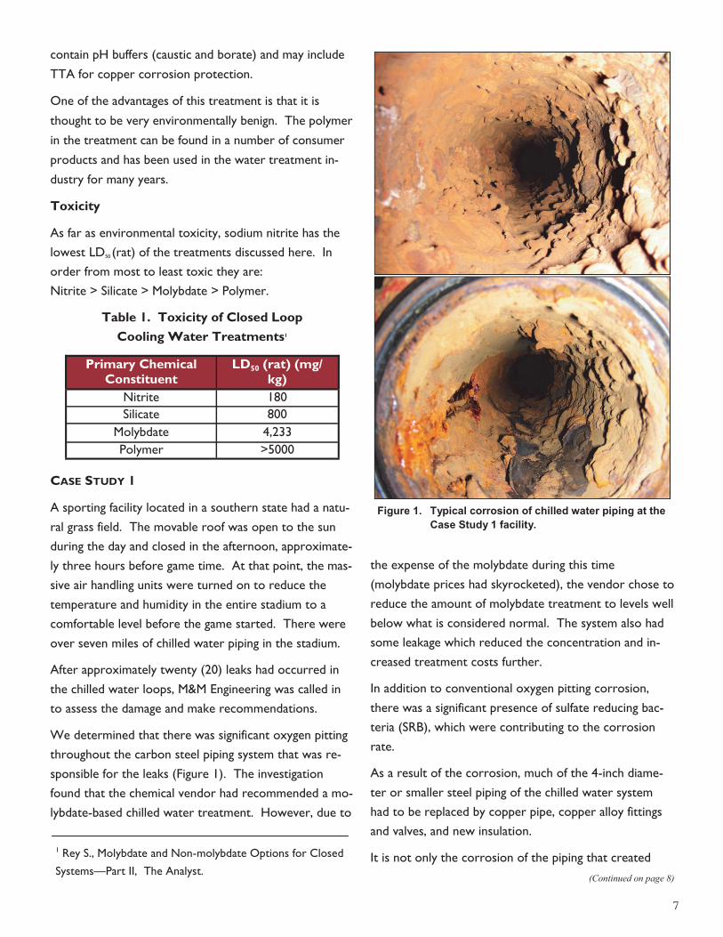
We determined that there was significant oxygen pitting
throughout the carbon steel piping system that was re-
sponsible for the leaks (Figure 1). The investigation
found that the chemical vendor had recommended a mo-
lybdate-based chilled water treatment. However, due to
the expense of the molybdate during this time
(molybdate prices had skyrocketed), the vendor chose to
reduce the amount of molybdate treatment to levels well
below what is considered normal. The system also had
some leakage which reduced the concentration and in-
creased treatment costs further.
In addition to conventional oxygen pitting corrosion,
there was a significant presence of sulfate reducing bac-
teria (SRB), which were contributing to the corrosion
rate.
As a result of the corrosion, much of the 4-inch diame-
ter or smaller steel piping of the chilled water system
had to be replaced by copper pipe, copper alloy fittings
and valves, and new insulation.
It is not only the corrosion of the piping that created
(Continued on page 8)
Primary Chemical
Constituent LD50 (rat) (mg/
kg)
Nitrite 180
Silicate 800
Molybdate 4,233
Polymer >5000
Figure 1. Typical corrosion of chilled water piping at the
Case Study 1 facility.
1 Rey S., Molybdate and Non-molybdate Options for Closed
Systems—Part II, The Analyst.
8
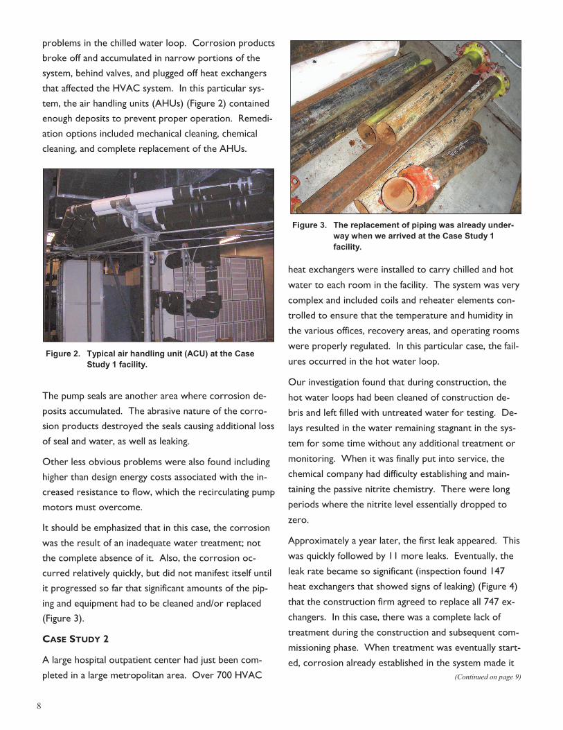
problems in the chilled water loop. Corrosion products
broke off and accumulated in narrow portions of the
system, behind valves, and plugged off heat exchangers
that affected the HVAC system. In this particular sys-
tem, the air handling units (AHUs) (Figure 2) contained
enough deposits to prevent proper operation. Remedi-
ation options included mechanical cleaning, chemical
cleaning, and complete replacement of the AHUs.
The pump seals are another area where corrosion de-
posits accumulated. The abrasive nature of the corro-
sion products destroyed the seals causing additional loss
of seal and water, as well as leaking.
Other less obvious problems were also found including
higher than design energy costs associated with the in-
creased resistance to flow, which the recirculating pump
motors must overcome.
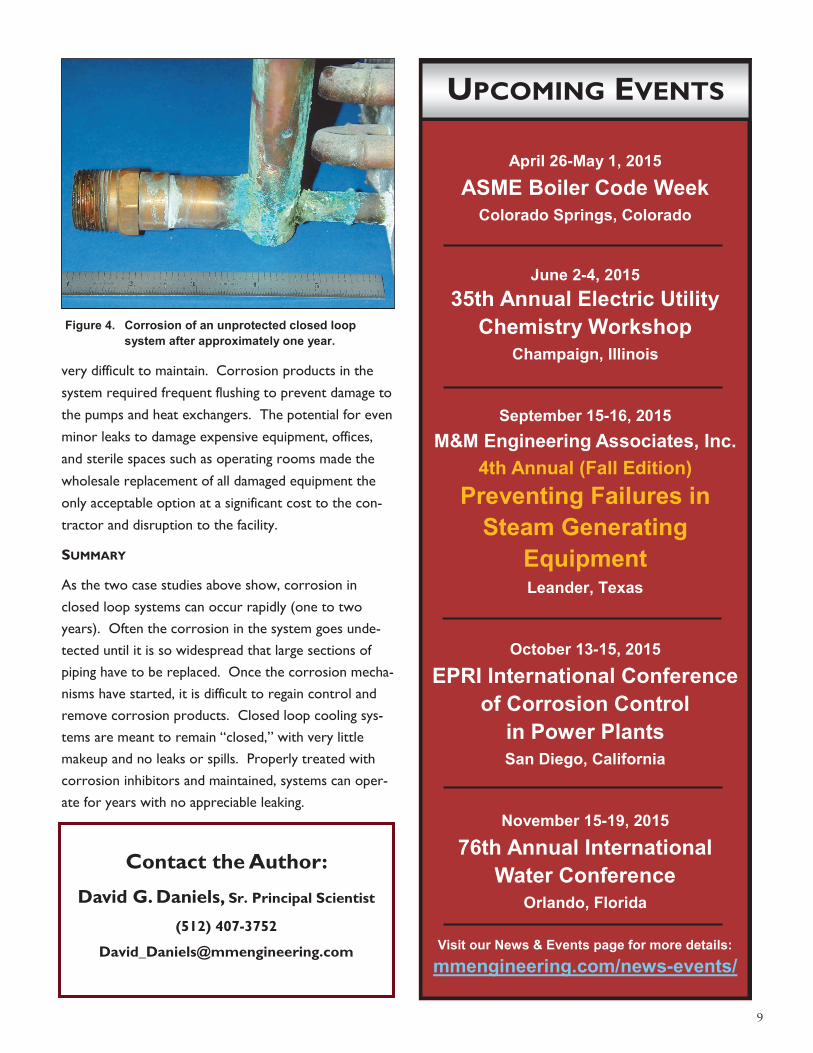
It should be emphasized that in this case, the corrosion
was the result of an inadequate water treatment; not
the complete absence of it. Also, the corrosion oc-
curred relatively quickly, but did not manifest itself until
it progressed so far that significant amounts of the pip-
ing and equipment had to be cleaned and/or replaced
(Figure 3).
CASE STUDY 2
A large hospital outpatient center had just been com-
pleted in a large metropolitan area. Over 700 HVAC
heat exchangers were installed to carry chilled and hot
water to each room in the facility. The system was very
complex and included coils and reheater elements con-
trolled to ensure that the temperature and humidity in
the various offices, recovery areas, and operating rooms
were properly regulated. In this particular case, the fail-
ures occurred in the hot water loop.
Our investigation found that during construction, the
hot water loops had been cleaned of construction de-
bris and left filled with untreated water for testing. De-
lays resulted in the water remaining stagnant in the sys-
tem for some time without any additional treatment or
monitoring. When it was finally put into service, the
chemical company had difficulty establishing and main-
taining the passive nitrite chemistry. There were long
periods where the nitrite level essentially dropped to
zero.
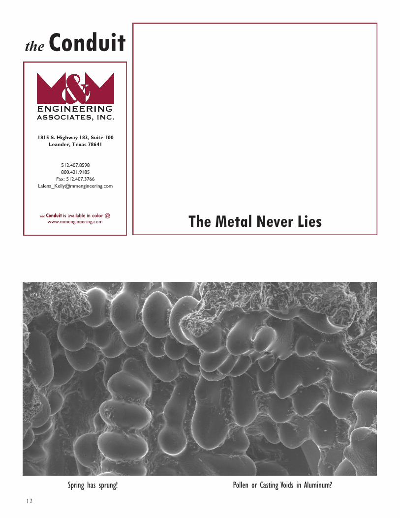
Approximately a year later, the first leak appeared. This
was quickly followed by 11 more leaks. Eventually, the
leak rate became so significant (inspection found 147
heat exchangers that showed signs of leaking) (Figure 4)
that the construction firm agreed to replace all 747 ex-
changers. In this case, there was a complete lack of
treatment during the construction and subsequent com-
missioning phase. When treatment was eventually start-
ed, corrosion already established in the system made it
(Continued on page 9)
Figure 2. Typical air handling unit (ACU) at the Case
Study 1 facility.
Figure 3. The replacement of piping was already under-
way when we arrived at the Case Study 1
facility.
9
April 26-May 1, 2015
ASME Boiler Code Week
Colorado Springs, Colorado
June 2-4, 2015
35th Annual Electric Utility
Chemistry Workshop
Champaign, Illinois
September 15-16, 2015
M&M Engineering Associates, Inc.
4th Annual (Fall Edition)
Preventing Failures in
Steam Generating
Equipment Leander, Texas
October 13-15, 2015
EPRI International Conference
of Corrosion Control
in Power Plants
San Diego, California
November 15-19, 2015
76th Annual International
Water Conference
Orlando, Florida
Visit our News & Events page for more details:
mmengineering.com/news-events/
very difficult to maintain. Corrosion products in the
system required frequent flushing to prevent damage to
the pumps and heat exchangers. The potential for even
minor leaks to damage expensive equipment, offices,
and sterile spaces such as operating rooms made the
wholesale replacement of all damaged equipment the
only acceptable option at a significant cost to the con-
tractor and disruption to the facility.
SUMMARY
As the two case studies above show, corrosion in
closed loop systems can occur rapidly (one to two
years). Often the corrosion in the system goes unde-
tected until it is so widespread that large sections of
piping have to be replaced. Once the corrosion mecha-
nisms have started, it is difficult to regain control and
remove corrosion products. Closed loop cooling sys-
tems are meant to remain “closed,” with very little
makeup and no leaks or spills. Properly treated with
corrosion inhibitors and maintained, systems can oper-
ate for years with no appreciable leaking.
Figure 4. Corrosion of an unprotected closed loop
system after approximately one year.
Contact the Author:
David G. Daniels, Sr. Principal Scientist
(512) 407-3752
UPCOMING EVENTS

10
Preventing Failures in Steam
Generating Equipment
M&M Engineering will host a Fall Edition of their 4th annual workshop for producers of
steam, be it used in power or process applications. The two day workshop focuses on the
issues most common in steam generating systems and is applicable to many industries
including: pulp and paper, refining, petro-chemical, and power generation.
Seating is limited - register TODAY!
September 15-16, 2015 — Leander, Texas
The registration fee for this two day event is $750 (continental breakfast and lunch are included).
The registration deadline is August 14, 2015*. For details, and to register online, visit:
http://mmengineering.com/events/event/4th-annual-preventing-failures-steam-generating-equipment-workshop-fall-edition/
Or contact Lalena Kelly by phone or email for further information:
(512) 407-3775 or [email protected]
Event Location: 1815 S. Highway 183, Leander, Texas 78641
*Subject to a minimum number of attendees. Once registered, attendees should confirm workshop before making travel
arrangements.
Equipment Associated with Steam Generation – A Primer
Utility Feedwater Heaters and Damage Mechanisms
Water Touched Boiler Tube Damage Mechanisms
Steam Touched Boiler Tube Failure Mechanisms Introduction to Nondestructive Testing &
Inspection Contracting High Energy Piping: Damage Mechanisms and
Corrections
Introduction to Failure Analysis Failure Investigation Principles for Combustion
Turbines Basic Steam Turbine Failures Condenser and Cooling Water Failures Damage Mechanisms in Deaerators Water and Steam Chemistry-Influenced Failures
in the Steam Cycle Discussion and Wrap Up
* (sessions are subject to change)
Day 1 Day 2

11
the Conduit is distributed
free of charge by M&M
Engineering Associates, Inc.
We welcome your comments,
questions, and suggestions,
and we encourage you to
submit articles for publication.
We grant limited permission
to photocopy all or part of
this publication for nonprofit
use and distribution.
For technical information
please contact:
David Daniels
(512) 407-3752 [email protected]
Mark Tanner
(512) 407-3777 [email protected]
Karen Fuentes
(512) 407-3778 [email protected]
__ Please add my name to your mailing list.
__ Please delete my name from your mailing list.
__ Please correct my information as listed below.
The Conduit is distributed both electronically and by traditional hardcopy. We
encourage our readers to receive copies electronically as it delivered by an email
containing a link for that quarters’ issue, and is presented in full color. If you prefer
to have a black and white hardcopy mailed, simply check the box below, otherwise
you will receive an email each quarter with a link to the latest issue.
I prefer to receive this newsletter by ____ Email _____ Mail
Name: ____________________________________________
Title: _____________________________________________
Company: _______________________________________ __
Address: ___________________________________________
City: ________________ State: _______ Zip: ____________
Phone: _______________ Fax: _________________ ______
Email: ____________________________________ ________
Comments on this issue: __________________________________
_____________________________________________ ____
___________________________________________ ______
__________________________________________ _______
Please send or fax this form to:
M&M Engineering Associates, Inc.
1815 S. Highway 183, Suite 100
Leander, Texas 78641
Fax: (512) 407-3766
Email: [email protected]
Web: http://mmengineering.com/publications-reports/conduit/
Texas • Illinois • Oregon • Wisconsin
www.mmengineering.com
12
Spring has sprung! Pollen or Casting Voids in Aluminum?
the Conduit
The Metal Never Lies
the Conduit is available in color @
www.mmengineering.com
1815 S. Highway 183, Suite 100
Leander, Texas 78641
512.407.8598
800.421.9185
Fax: 512.407.3766