Embed Size (px)
Citation preview
8/9/2019 Conduit Guide
http://slidepdf.com/reader/full/conduit-guide 1/34
G U I D E L I N E S F O R I N S T A L L I N G
S T E E L C O N D U I T / T U B I N G

8/9/2019 Conduit Guide
http://slidepdf.com/reader/full/conduit-guide 2/34
Lets You Plot MagneticField Density
ElectroMagnetic Interference (EMI) can
significantly reduce the effectiveness of
computers and other sophisticated electronic
equipment. It can cause problems ranging
from distortion of monitor images to the
alteration or destruction of valuable digital
data and the disruption of communications.
Georgia Tech—under the sponsorship
of the Steel Tube Institute of North America
(STI)—has conducted in-depth research on
reducing the effect of electromagnetic fields
on electrical and electronic equipment.
The result is the Grounding and
ElectroMagnetic Interference (GEMI)
analysis software, available free from STI.
It lets you accurately calculate the
electromagnetic field density of a network
design for conduit-enclosed circuits. Theresearch shows that steel conduit can reduce
electromagnetic fields at 60 Hz power
frequency levels by as much as 95%.
Lets You DetermineMaximum AllowableLength Of EquipmentGrounding Conductor
The GEMI software also includes research on
equipment grounding and a new Steel ConduitInstallation Guide. GEMI lets you confirm
design parameters of grounding systems that
use steel electrical conduit and helps you
determine whether your electrical designs
comply with the equipment grounding
requirements of the NEC.
For your free copy of the GEMI CD,contact the Steel Tube Institute,2000 Ponce de Leon, Suite 600,Coral Gables, FL 33134E-mail: [email protected]
For copies of the research reports and newinstallation guide, visit the conduit website:http://www.steelconduit.org
Free
WindowsGEMI
Software
®

8/9/2019 Conduit Guide
http://slidepdf.com/reader/full/conduit-guide 3/34
Section .................................................................................................................................................. Page
1. Scope .......................................................................................................................................................1
2. Glossary ..................................................................................................................................................2
3. General Product Information ..............................................................................................................4
3.1 Steel Conduit and Tubing......................................................................................................................4
3.2 Manufactured Elbows, Nipples and Couplings ....................................................................................5
4. General Installation Procedures ..........................................................................................................7
4.1 Conduit Cutting and Threading Guidelines ..........................................................................................7
4.2 Bending Guidelines ...............................................................................................................................9
4.3 Fittings for use with RMC, IMC and EMT ........................................................................................12
4.4 Support of Raceways...........................................................................................................................15
4.5 Firestopping and Fire Blocking...........................................................................................................16
4.6 Corrosion Protection ...........................................................................................................................174.7 Equipment Grounding Using Steel Conduit .......................................................................................18
5. Specific Installation Requirements ....................................................................................................20
5.1 General ................................................................................................................................................20
5.2 Protection Against EMI.......................................................................................................................20
5.3 Raceways Installed in Concrete ..........................................................................................................20
5.4 Communications Circuits....................................................................................................................21
5.5 Underground Services.........................................................................................................................21
5.6 Verification of Installation...................................................................................................................21
6. Installation Practices for PVC-Coated Conduit and Fittings .........................................................22
6.1 Tools ....................................................................................................................................................22
6.2 Clamping (Vising) PVC-Coated Conduit ...........................................................................................22
6.3 Cutting and Threading PVC-Coated Conduit .....................................................................................23
6.4 Bending PVC-Coated Conduit............................................................................................................24
6.5 Installing PVC-Coated Conduit ..........................................................................................................24
6.6 Patching Damaged Areas ....................................................................................................................25
6.7 Equipment Grounding and Bonding ...................................................................................................25
ANNEX A: Threading Conduit..............................................................................................................26
ANNEX B: Grounding and EMI ...........................................................................................................27
ANNEX C: Reference Standards ...........................................................................................................30
Table of Contents

8/9/2019 Conduit Guide
http://slidepdf.com/reader/full/conduit-guide 4/341
This standard covers the installation of steel rigid
metal conduit (RMC), steel intermediate metal conduit
(IMC), and steel electrical metallic tubing (EMT).
Conduit with a supplementary PVC coating is also
included. These conduits are used as raceway systems
for electrical wiring in residential, commercial, andindustrial occupancies. This standard includes
information on fittings and other applicable
accessories necessary for a quality installation of these
raceways. All information in this publication is
intended to comply with the National Electrical Code®
(NFPA Standard 70). Installers should always follow
the NEC and/or state and local codes as applicable to
the jurisdiction, and the manufacturers’ instructions
when installing electrical products and systems.
Installations must be performed “in a neat andworkmanlike manner.” This is one of the most basic
and important requirements for electrical wiring in the
National Electrical Code.
It is essential that the installer be concerned, informed,
and have pride in the finished product. Maintaining
the effectiveness of Code requirements depends on
selecting the right product for the specific job, good
installation workmanship, and proper maintenance
during the life cycle.
This document is intended to enhance electrical safety
by aiding the installer in meeting the “neat and
workmanlike” requirements, reducing future repair
needs, providing for future expansion to avoid
electrical overload, creating an installation which will
protect the wire conductors from mechanical abuse,
and providing electrical continuity of the raceway
system.
NOTE: For continuing updated information on thisdocument, check www.steelconduit.org
1. Scope

8/9/2019 Conduit Guide
http://slidepdf.com/reader/full/conduit-guide 5/342
Alternate corrosion protection
A coating(s), other than one consisting solely of
zinc, which, upon evaluation, has demonstrated the
ability to provide the level of corrosion resistance
required on the exterior of the conduit. It is not
prohibited that the coatings include zinc.
Approved
Acceptable to the authority having jurisdiction.
NOTE: “The authority having jurisdiction” is most
often the electrical inspector, but could be a project
manager or other final approval authority.
Authority having jurisdiction (AHJ)
The organization, office, or individual with the
authority to determine which code requirements
apply, how they are to be interpreted, and whogives final approval to the electrical installation.
Some examples are the electrical inspector or other
government entity and insurance underwriters.
Bend
A curvature of the conduit or tubing made so the
raceway will fit a specific geometric location. This
can be a factory elbow or can be a field bend of the
raceway.
Circuit loading
Concentration of circuits in one raceway.
Conduit connection
Interface between conduit or tubing and other
equipment.
Conduit joint
The coupling of two pieces of conduit or tubing, or
coupling a length of conduit or tubing to a bend.
NOTE: One of the most important elements of anelectrical installation.
Coupling, integral
A coupling meeting the requirements of UL 514B
which is assembled to the conduit, tubing, or elbo
during manufacture and is not readily removable.
The integral coupling of electrical metallic tubing
is a “belled” end with set screws.
Coupling, standard conduit
As applied to IMC or steel RMC this is a threaded
straight-tapped means of joining two pieces of
conduit. Such coupling meets the requirements of
the applicable UL conduit standard.
Equipment grounding conductor
As defined in the NEC. In addition, it is the path b
which a fault is transmitted to the overcurrent
protection device. NOTE: Steel conduit and tubing are called
equipment grounding conductors, as are copper o
aluminum wire.
Firestopping
Using approved materials (generally detailed by
building codes or specifications) which fill the
opening (annular space) around the conduit to
prevent the spread of fire and smoke and assure th
fire rating of the wall, floor, or ceiling being
penetrated is not reduced.
Fire-resistance-rated assemblies
Construction materials assembled together, then
tested and rated for ability to inhibit the spread of
fire for a specified period of time under specific
test conditions. The rating is expressed in hours;
e.g. 1 hour, 2 hour, etc. Information can be found
various laboratory “listing” directories.
Fitting, threadlessA fitting intended to secure, without threading,
rigid or intermediate metal conduit or electrical
metallic tubing to another piece of equipment
(connector) or to an adjacent length of conduit or
tubing (coupling).
2. Glossary (as used in this Standard)

8/9/2019 Conduit Guide
http://slidepdf.com/reader/full/conduit-guide 6/343
Galvanized
Protected from corrosion by a specified coating of
zinc which may be applied by either the hot-dip or
electro-galvanized method.
Home run
The run of raceway between the
panelboard/switchboard and the first distribution
point.
Identified (for use)
As defined in the NEC.
NOTE: For the purposes of this standard the
product has been evaluated for a specific purpose,
environment or application and written
documentation or labeling verifying this exists.
Penetration firestop system
A listed assemblage of specific materials or
products that are designed, tested and fire
resistance-rated in accordance with ASTM E814 to
resist, for a prescribed period of time, the spread of
fire through penetrations in fire-rated assemblies.
Primary coating
The corrosion protection coating evaluated by the
listing authority and required by the applicable
standard for listing.
Running threadsContinuous straight threads cut into a conduit and
extended down its length – not permitted on
conduit for connection at couplings.
Raceway
As defined in the NEC, this term includes more
than steel conduit. In this standard it is steel rigid
metal conduit, intermediate metal conduit, or
electrical metallic tubing, designed for enclosing
and protecting electrical, communications,
signaling and optical fiber wires and cables.
Supplementary coating
A coating other than the primary coating applied to
listed conduit/tubing either at the factory or in the
field to provide additional corrosion protection
where needed.

8/9/2019 Conduit Guide
http://slidepdf.com/reader/full/conduit-guide 7/344
3.1 Steel Conduit and Tubing
The wall thickness and strength of steel make
RMC, IMC, and EMT the wiring methods
recognized as providing the most mechanical
protection to the enclosed wire conductors.Additionally, a properly installed steel RMC, IMC
or EMT system is recognized by the NEC as
providing its own equipment grounding path.
3.1.1 Steel rigid metal conduit - RMC (ferrous
metal)
(NOTE: While the scope of the National Electrical
Code Article for Rigid Metal Conduit – Type RMC
includes conduits manufactured from aluminum,
stainless steel, red brass, or other metals they arenot covered by this standard.)
Steel Rigid Metal Conduit (RMC) is a listed
threaded metal raceway of circular cross section
with a coupling which can be either a straight
tapped conduit coupling (see Figure 1) or the
integral type (see Figure 4).
Threads are protected on the uncoupled end by
color-coded thread protectors which keep them
clean and sharp and aid in trade size recognition.
Steel RMC is available in trade sizes 1/2 through 6.
Thread protectors for trade sizes 1, 2, 3, 4, 5, and 6
are color-coded blue; trade sizes 1/2, 1-1/2, 2-1/2,
3-1/2 are black, and trade sizes 3/4 and 1-1/4 are
red. (See Table 1 for Metric Trade Size
Designators.) The nominal finished length of RM
with coupling is 10 feet (3.05m). Longer or short
lengths with or without coupling and threaded or
unthreaded are permitted.
Steel RMC can have a primary coating of zinc, acombination of zinc and organic coatings, or a
nonmetallic coating with or without zinc (such as
PVC). Other supplementary coatings can be appli
to all three where additional corrosion protection
needed.
(NOTE: Contact suppliers with product-specific
questions).
Special installation practices and tools are general
required for working with PVC-coated products.These practices are covered in Section 6.
Steel RMC is the heaviest-weight and thickest-wa
steel conduit. Where galvanized by the hot-dip
process, it has a coating of zinc on both the inside
and outside. Electro-galvanized rigid has a coating
of zinc on the exterior only, with corrosion-resista
organic coatings on the interior. Steel RMC with
alternate corrosion protection generally has organ
coatings on both the exterior and the interior
surfaces. Galvanized RMC has no temperature
limitations and can be used indoors, outdoors,
underground, concealed or exposed. RMC with
coatings that are not zinc-based sometimes has
temperature limitations or is not listed for use in
environmental air spaces; consult manufacturers’
listings and markings.
3.1.2 Intermediate metal conduit – IMC (ferrous
metal)
(NOTE: IMC is only manufactured from steel)
Intermediate Metal Conduit (IMC) is a listed
threaded steel raceway of circular cross section
with a coupling which can be either a straight-
tapped conduit coupling (see Figure 2) or the
3. General Product Information
Figure 1: Steel Rigid Metal Conduit (RMC)

8/9/2019 Conduit Guide
http://slidepdf.com/reader/full/conduit-guide 8/345
Figure 2: Intermediate Metal Conduit (IMC) Figure 3: Electrical Metallic Tubing (EMT)
integral type (see Figure 4). Threads are protected
on the uncoupled end by color-coded thread
protectors which keep them clean and sharp and aid
in trade size recognition. IMC is available in trade
sizes 1/2 through 4. Thread protectors for trade
sizes 1, 2, 3, 4, are color-coded orange; trade sizes1/2, 1-1/2, 2-1/2.
3-1/2 are yellow; and trade sizes 3/4 and 1-1/4 are
green. (See Table 1 for Metric Trade Size
Designators.) The nominal finished length of IMC
with coupling is 10 feet (3.05m).
IMC has a reduced wall thickness and weighs
about one-third less than RMC. The outside has a
zinc based coating and the inside has an organic
corrosion-resistant coating. IMC is interchangeablewith steel RMC. Both have threads with a 3/4-inch
per foot (1 in 16) taper; use the same couplings and
fittings; have the same support requirements; and
are permitted in the same locations.
3.1.3 Electrical metallic tubing - EMT (ferrous
metal)
(NOTE: Aluminum EMT is not covered by this
standard.)
Electrical Metallic Tubing (EMT), also commonly
called thin-wall, is a listed steel raceway of circular
cross section which is unthreaded, and nominally
10 feet (3.05m) long (see Figure 3). The outside
corrosion protection is zinc-based and the inside
has an organic corrosion-resistant coating. Trade
sizes are 1/2 through 4. (See Table 1 for Metric
Trade Size Designators.) EMT is installed by use
of set-screw or compression-type couplings andconnectors. EMT is permitted to have an integral
coupling which is comprised of a “belled” end of
the tube with set screws (see Figure 4).
3.1.4 PVC-coated conduit — (See Section 6)
3.2 Manufactured Elbows, Nipples, and
Couplings
3.2.1 Factory elbows
Elbows are bent sections of conduit or tubing used
to change raceway direction or bypass obstructions.
IMC and RMC elbows are threaded on each end.
Elbows of the correct type and dimensions are an
important element of the raceway installation.
Factory-made elbows in both standard and special
radius are readily available for all sizes of steel
RMC, IMC, and EMT. Elbows with integral
couplings are available in trade sizes 2-1/2 through
4. Specialized large radius elbows, often referred to
as “sweeps,” are also available. They are custom
ordered to solve various installation problems.
Some typical uses of sweeps are to facilitate easier

8/9/2019 Conduit Guide
http://slidepdf.com/reader/full/conduit-guide 9/346
wire pulling, install conduit in limited or
geometrically difficult space, provide specific stub-
up length, or enhance protection of communication
or fiber optic cables during pulls.
Physical dimensions of factory-made elbows forRMC, IMC, and EMT vary between manufacturers.
When installing factory elbows for a job, being
aware of this variability can avoid installation
problems. Always measure to be safe. To order
factory elbows, you need to specify the raceway
type, trade size, and angle of bend. If ordering a
special radius elbow, the radius will also have to be
specified.
3.2.2 Nipples
A nipple is a short length of conduit or tubing
material which is used to extend the system.
Nipples are used between conduit and items such
as (but not limited to) fittings, boxes, and
enclosures or between two boxes, two enclosures,
etc. When nipples are used to extend a conduit run
to an enclosure, box, etc., the percentage wire fill
requirements shown in Chapter 9, Table 1 of the
NEC apply; for example, 40-percent fill for three
or more conductors.
When a nipple is installed between boxes,
enclosures, etc. and the nipple does not exceed 24
inches (610 mm), wire fill is permitted to be 60%.
Factory-made RMC nipples are threaded on both
ends and are readily available in all sizes in length
12 inches (305 mm) and under. Longer lengths are
available by special order or may be field-
fabricated.
3.2.3 Couplings
Each length of steel RMC and IMC is furnished
with a coupling on one end. Additional threaded
couplings are readily available for all conduit size
Steel RMC and IMC with an integral coupling are
available in trade sizes 2-1/2 through 4. This is a
coupling which permits joint make-up by turning
the outside coupling rather than the conduit (see
Figure 4). EMT with an integral coupling is
available in trade sizes 1-1/4 through 4. The EMT
has a belled end with set-screws (see Figure 4).
For threadless fittings for use with RMC, IMC, an
EMT, see section 4.3.
(NOTE: See Section 6 for installation practices for
PVC-coated conduit and fittings.)
Table 1: Metric Trade Size Designators forRMC, IMC, and EMT
*Trade Size DesignatorEnglish Metric
1/2 16
3/4 21
1 27
1 1/4 35
1 1/2 41
2 53
2 1/2 63
3 78
3 1/2 91
4 103
5 129
6 155
*Identifier only; not an actual dimension Figure 4: EMT, IMC and RMC with integral coupling

8/9/2019 Conduit Guide
http://slidepdf.com/reader/full/conduit-guide 10/347
(NOTE: See Section 6 for installation practices for
PVC-coated conduit and fittings.)
4.1 Conduit Cutting and Threading Guidelines
Close attention to measuring the exact length of conduit needed is important for a quality installation.
4.1.1 Cutting and threading steel RMC and IMC
(NOTE: Although coupling threads are straight
tapped, conduit threads are tapered.)
Field threading is to be performed in accordance with
the following procedures unless manufacturer’s
instructions differ. The operating and safety
instructions should be read and understood priorto operating the equipment.
Use a standard 3/4 inch per foot (1 in 16) taper
National Pipe Thread (NPT) die. The threads shall be
cut full and clean using sharp dies. (See ANSI/ASME
B.1.20.1-1983 (R2001) Standard for Pipe Threads,
General Purpose (Inch).
b) Do not use worn dies. Although ragged and torn
threads or threads which are not cut deep enough can
be caused by poor threading practices; they can also
indicate worn dies. If inspection shows this to be
true, see Annex A for procedure to change dies.
c) To adjust the dies, loosen the screws or locking
collar that hold the cutting dies in the head. When thescrews or collar are loosened, the dies should move
freely away from the head.
d) Screw the die head onto the threaded portion of a
factory-threaded nipple or factory-threaded conduit
until the die fits the factory thread. If the die head has
an adjusting lever, set the head to cut a slightly
oversized thread.
(NOTE: This will ordinarily be one thread short of
being flush with the face of a thread gauge when thegauge is hand tight. This is within the tolerance
limits which allow the thread to be one thread short
or long of being flush with the gauge face.)
e) Tighten the screws or locking collar so that the
dies are tightly held in the head.
f) Remove the set-up piece of threaded conduit. The
die is ready for use.
4. General Installation Practices
Figure 5: Lower the roll cutter to the desired length.
Tighten the handle about one quarterture per each
revolution and repeat until conduit is cut through.
Figure 6: The roll cutter will leave a burr on the
inside diameter of the conduit. The burr must be
removed to ensure that the wire insulation will not be
damaged during pulling.

8/9/2019 Conduit Guide
http://slidepdf.com/reader/full/conduit-guide 11/348
g) After adjusting the dies as outlined above, proceed
as follows:
h) Cut the conduit with a saw or roll cutter. Be
careful to make a straight cut (see Figure 5).
(NOTE: If the die is not started on the pipe squarely,
crooked threads will result. When using the wheel
and roll cutter to cut pipe, the cutter must be revolved
completely around the pipe. Tighten the handle about
one quarter turn after each rotation and repeat this
procedure until the pipe is cut through.)
i) After cutting and prior to threading, ream the
interior and remove sharp edges from the exterior
(see Figures 6, 7 and 8).
(NOTE: Reaming the conduit after threading will
stretch or oval the end of the conduit.)
j) To start a universal die head, press it against the
conduit end with one hand and turn the stock with
the other (see Figures 10 and 11).With a drop head
die, the stock remains stationary and the head rotates.
After the dies have engaged for a thread or two, they
will feed along without pressure.
k) Stop the cutting as soon as the die has taken holdand apply thread cutting oil freely to the dies and the
area to be threaded (see Figure 9).
(NOTE: Frequent flooding of the dies with a good
grade of cutting oil will further safeguard against
poor threads. The oil keeps the material lubricated
and insures a smoother cut by reducing friction and
heat. Insufficient cutting oil will also cause ragged
threads. The flow of the cutting fluid to the die headshould be such that the cutting surfaces of the die
segments are flooded. As a general rule, there is no
such thing as too much oil at the die head.)
l) Thread one thread short of the end of the chaser.
(NOTE: It is a good practice to thread one thread
short to prevent butting of conduit in a coupling and
allow the coupling to cover all of the threads on the
conduit when wrench tight.)
m) Back the die head off and clean the chips from th
thread (see Figure 10).
4.1.2 Importance of thread length
The length of the thread is important and the
applicable UL requirements specify the manufacture
length of the thread and the tolerance. A ring gauge
used to determine the correct thread length at the
factory (see Figures 11 and 12). Good practice is to
thread the conduit one thread short. This is to prevenconduit from butting inside the coupling. This
practice will permit a good electrical connection
between the conduits and couplings.
Figure 7: Insert the (flute) reamer into work piece and
rotate until burr is removed.
Figure 8: A minimal amount of pressure will remove
the burr completely and eliminate possible flaring of
the conduit end.

8/9/2019 Conduit Guide
http://slidepdf.com/reader/full/conduit-guide 12/349
To insure that the threads are properly engaged, the
coupling should be made up hand-tight, then wrench
tightened. Generally, wrench-tightening should not
exceed three additional threads (see Figure 13). It
should never be necessary to use an extension handle
on a wrench to make up a tight joint. The only timean extension handle should be used is to dismantle a
stubborn joint in an existing line.
A simple rule regarding the use of tools is to select
the right type and the right size. The proper size
wrench for a given conduit size trade is indicated in
Table 2.
4.1.3 Protection of field cut threads
NEC Section 300.6 (A) requires that where corrosion
protection is necessary and the conduit is threaded in
the field, the thread shall be coated with an approved
electrically-conductive, corrosion resistant compound(see Figure 20). Coatings for this purpose, listed
under UL category “FOIZ” are available. Zinc-rich
paint or other coatings acceptable to the AHJ may be
used.
(NOTE: Corrosion protection is provided on factory-
cut threads at time of manufacturing.)
4.1.4 Cutting EMT
Cut the EMT square using a hack saw or band saw.Do not use roll-type tubing cutters.
(NOTE: Roll-type cutters require reaming which
flares the wall of EMT, making fittings difficult to
install.)
A tool designed for the purpose is best for reaming
the inside of EMT. Where side cutter pliers or other
general tools are used, take special care not to flare
the ends.
4.2 Bending Guidelines
The variety of electrical installations makes field
bending necessary. While a full range of factory
elbows are readily available, they do not address the
Figure 9: When proper thread length is achieved the
end of the conduit becomes flush with the ends of the die
segments.
Figure 10: Wire brush the threads to remove any
shavings or debris.
Table 2:Proper Wrench Size
Conduit Trade Size Wrench Size
under 1/2 10"1/2 12"
3/4 through 1 1/4 14"
1 1/2 18"
2 – 2 1/2 24"
3 – 4 36"
5 - 6 48"

8/9/2019 Conduit Guide
http://slidepdf.com/reader/full/conduit-guide 13/3410
variability of stubs, back-to-back, offset, and saddle
bends encountered in the field-routing of conduit and
EMT. These most commonly-used types of bends
can be quickly, efficiently, and economically made by
a knowledgeable and experienced installer. The skills
needed to obtain a level of proficiency are readily
learned and require knowledge of basic mathematics,
industry terminology and bending tools.
Manufacturers of bending equipment publish
manuals for each specific bender model which
provide excellent in-depth information on bending
conduit. The information in this section is
supplemental to that provided by the manufacturers.
Contact bender manufacturers for complete
information.
4.2.1 General information
a) Read and understand all the bender manufactureroperating and safety instructions before operating
their equipment.
b) It is extremely important that the bender, its
components and accessories are matched to the
conduit type and size being bent because of the
forces being applied. When using a power bender, it
is important that pins are in the proper pin holes for
the conduit size.
c) Although the National Electric Code allows up to360 degrees between pulling points, using as few
bends as possible, and none exceeding 90 degrees,
will make wire pulling easier. The fewer total degre
between pulling points and the use of shallow bends
combine to reduce the strain created by pulling wire
For multi-conductor control cable and
communications cable, it is recommended that runs
be limited to two 90 degree bends (a total of 180
degrees) per EIA/TIA-569 Commercial Building
Standard for Telecommunications Pathways and
Spaces.
d) Before placing the conduit in the bender,
accurately measure and mark the conduit with a thin
Figure 11: Threads should be checked with a NPT-L1
threaded ring gauge to ensure proper make up.
Figure 12: A proper thread should be free from chips or
tears over the entire length.
Figure 13: The coupling must be assembled wrench tight.

8/9/2019 Conduit Guide
http://slidepdf.com/reader/full/conduit-guide 14/3411
line that goes completely around the conduit. This
will assure the mark is visible if the conduit needs to
be rotated.
e) All radius measurements shall be made to the
centerline of the bend and shall comply with NEC,Chapter 9, Table 2. See EIA/TIA-569 Commerical
Building Standard for Telecommunications Pathways
and Spaces for guidance on bend radius for conduits
used with communications and optical fiber cables.
f) Where hand benders do not have degree markings,
degrees of bend shall be measured to the inner edge
of the conduit; the surface that fits in the groove.
g) Where it is necessary to compensate for spring
back, slightly overbend.
h) When using a hand bender, choose a solid, flat
surface. Pin the conduit firmly to the surface with
steady foot pressure sufficient to keep the conduit
and bender marks aligned and the conduit nestled in
the groove throughout the full arc of the bend.
4.2.2 Bending steel RMC
(NOTE: Benders recommended for a larger size
range may be capable of bending some sizes belowtheir primary range if so equipped.)
Trade sizes 1/2, 3/4, and 1 can be bent with a hand-
type bender. Trade sizes 1-1/4 and 1-1/2 require a
power bender or a mechanical ratchet-type bender.
Bend trade sizes 2 and larger on a power bender.
Do not put conduit ends in the hook or bending shoe
of the bender because thread damage and end
flattening will occur.
When an EMT bender is designated as suitable for
bending rigid conduit, a bender shoe one trade size
larger than the conduit to be bent is to be used. Using
the EMT bender will result in a slightly larger radius.
4.2.3 Bending IMC
A full shoe or universal bender is the preferred
bending tool for IMC. Limit hand bending to trade
sizes 1/2, 3/4, and 1. To make hand bending of trade
size 1 easier, use a two position foot-pedal bender.This allows more weight to be applied for leverage.
Trade sizes 1-1/4 and 1-1/2 require a power bender or
a mechanical ratchet-type bender. Trade sizes 2 and
larger require a power bender.
(NOTE: Benders recommended for a larger size
range may be capable of bending some sizes below
its primary range if so equipped.)
4.2.4 Bending EMT
Use a bender of the correct trade size designed for
bending EMT. EMT trade sizes 1/2, 3/4, and 1 can be
bent with hand benders because of the thinner wall.
Use a mechanical ratchet-type bender for trade sizes
1-1/4 and 1-1/2. Use a power bender for trade sizes 2
and larger.
(NOTE: Bending EMT in an oversized EMT bender
will flatten the bend and possibly kink the tube.)
When making a short radius bend, straightening stubsin concrete, or applying greater than normal stress to
bend 1/2 or 3/4 EMT, place a mandrel into the EMT
to support the wall. Any object that can be inserted to
support the wall and is flexible enough to be bent and
is removable can be used. A spring, rope, or hose are
typical items used. Use a lubricant to aid in
extracting the mandrel.
Knocked-down EMT stubs which can be bent using a
hand bender (1/2 through 1) can be straightened by
placing the bender handle over the stub and pullingback to the desired position. If kinked, insert a
driftpin, working it back and forth while inserting;
this should force the tube back to round.

8/9/2019 Conduit Guide
http://slidepdf.com/reader/full/conduit-guide 15/3412
To shift the position of a stub of a vertical run when
the stub is slightly out of line, remove handle from
bender and place bender head on the EMT with the
step-end of bender down. Brace bender head with
your foot and apply pressure against tube and pull.
Overbend the stub slightly beyond the intendedposition to compensate for springback. Place handle
back into bender and bend to desired vertical
position.
When a stub or horizontal run is located close to the
floor, remove concrete from around the EMT
raceway. Put the bender in the stub with the step-end
down, brace with your foot and bend.
(NOTE: If step-end is not down, the bender could get
wedged during the bending process.)
To bend EMT coming out of a wall, remove handle
and insert a close nipple. Thread a 90 degree pipe
elbow onto the nipple and thread the handle into the
elbow. The handle will parallel the bender center.
This provides clearance to swing the handle down to
make the bend.
4.3 Fittings For Use With Steel RMC, IMC, and
EMT
(NOTE: See Section 6 for PVC-coated conduit)
4.3.1 Size and raceway type
Before installing a fitting or a raceway support,
review the packaging labels containing specific
applications for which the fitting or raceway support
is recommended and/or listed.
(NOTE: Do not take applications for granted. Many
fitting designs look the same but may contain subtleconstruction differences designed to enhance
performance in particular applications. Listed fittings
contain required, informative markings and any
specific conditions for use. For specific selection and
installation guidelines, consult NEMA FB2.10,
“Selection and Installation Guidelines for Fittings
for Use with Nonflexible Metallic Conduit and
Tubing”.)
Fittings and raceway supports shall be used only wi
conduit of the trade size indicated on the fitting or
raceway support or its smallest unit shipping
container.
4.3.2 Fittings for special applications
Threadless fittings intended for use in wet locations
are marked “Wet locations” on the fitting or its
smallest unit shipping container. Fittings marked
“Raintight” are suitable for use in “Wet Locations”.
A threadless fitting designed for use in wet location
that requires a gasket or sealing ring installed
between the fitting and a box shall be installed only
with the specific component marked on the fitting’s
smallest unit shipping container.
(NOTE: “Liquidtight” fittings are not necessarily
suitable for use in applications where submersion in
water is expected. ”Wet Locations” fittings are not
necessarily considered “Liquidtight. “Liquidtight”
fittings are intended for use in typical wet locations
and also in “wet” industrial environments which ma
contain machine oils and coolants.)
RMC and IMC fittings for use in industrial
applications involving sprayed mineral oils andcoolants are marked “Liquidtight” on the fitting or
smallest unit shipping container. Threadless fittings
intended for embedment in poured concrete are
marked “Concrete-tight” or “Concrete-tight when
taped” or ”Wet Locations” on the fitting’s smallest
unit shipping container.
(NOTE: Taping is adequate to prevent the entrance
of concrete aggregate into the raceway or box.
Concrete aggregate consists of cement combined wi
inert material such as coarse sand. When hardenedsuch aggregate may be abrasive and might pose a
risk to abrade conductor insulation or effectively
reduce the area inside the raceway. Fittings listed
as”Wet Locations” are also “Concrete-tight”.)

8/9/2019 Conduit Guide
http://slidepdf.com/reader/full/conduit-guide 16/3413
4.3.2.2 Expansion and deflection fittings
Expansion fittings shall be installed where significant
temperature differentials are anticipated. When
conduit is installed as outdoor raceway spans
between buildings, attached to bridges, on rooftops,etc., where expansion and contraction would result
from the direct heat of the sun coupled with
significant temperature drops at night, the full
coefficient of expansion shall be applied in
determining the need for expansion fittings. Table 3
shows length changes for steel conduit and tubing at
selected temperature differentials.
(NOTE: Expansion fittings are not generally
necessary because the coefficients of expansion for
steel and common building materials are so similar.)
Strong consideration should be given to the use of
deflection fittings or other approved means when
crossing a construction joint used in buildings,
bridges, parking garages, or other structures.
Structural construction joints will experience shear
and lateral loads due to gravity, expansion and
contraction and movement of the structure. Where
significant expansion is expected, expansion fittings
can be installed in-line with a deflection fitting or a
combination expansion/deflection fitting can be used.
4.3.3 Installing fittings
4.3.3.1 Threadless fittings
Threadless fittings shall not be assembled to threaded
RMC or IMC unless specifically recommended by
the fitting manufacturer. Where threadless fittings are
to be assembled to steel RMC, IMC and EMT,
conduit ends shall:
a) have squarely cut ends, free of internal and
external burrs, and circular form as provided from the
factory,
b) be free from dirt or foreign matter on the surface
of the conduit to be inserted into the fitting, and
c) have the ends of the conduit or tubing assembled
flush against the fitting’s end stop. Careful
consideration shall be given to the torque applied to
the fitting’s securement means.
Table 3: Expansion Characteristics of Steel Conduit and Tubing
Coefficient of Thermal Expansion = 0.65 x 10 -5in./in./°F*
TemperatureChanges inDegrees F
Length ChangeSteel Conduitin./100 feet
TemperatureChanges inDegrees F
Length ChangeSteel Conduitin./100 feet
TemperatureChanges inDegrees F
Length ChangeSteel Conduitin./100 feet
TemperatureChanges inDegrees F
Length ChangeSteel Conduitin./100 feet
5 0.04 55 0.43 105 0.82 155 1.21
10 0.08 60 0.47 110 0.86 160 1.25
15 0.12 65 0.51 115 0.90 165 1.29
20 0.16 70 0.55 120 0.94 170 1.33
25 0.20 75 0.59 125 0.98 175 1.3730 0.23 80 0.62 130 1.01 180 1.40
35 0.27 85 0.66 135 1.05 185 1.44
40 0.31 90 0.70 140 1.09 190 1.48
45 0.35 95 0.74 145 1.13 195 1.52
50 0.39 100 0.78 150 1.17 200 1.56
*A Fine Print Note in Section 300.7(B) of the NEC ® refers the user to the Expansion Characteristics of PVC ,Table 352.44(A) for Rigid Nonmetallic Conduit and suggests multiplying the lengths in that table by 0.20 in order to obtain a nominal number for steel conduit. Since the coefficient of steel conduit is between 2-3 times less than that of PVC conduit you would need more expansion fittings for PVC conduit, for a given temperature and length than for steel conduit. We have used the coefficient of expansion of steel, rather than the 0.20 multiplier, to calculate the exact length of change figures in Table 3.

8/9/2019 Conduit Guide
http://slidepdf.com/reader/full/conduit-guide 17/3414
(NOTE: Listed fittings are tested under prescribed
torque which represent normal, not excessive force.
Performance is not enhanced, and can be reduced,
by over- torquing the fitting’s securement means.)
4.3.3.2 Set-screw type
The length of screws provided with set-screw type
fittings varies. The appropriate torque for some
designs is reached when the head of the screw
touches a screw boss on the fitting. This cannot be
universally relied upon, however. Screws on certain
fitting designs, particularly larger trade sizes, can
offer more than one tightening option including
screwdriver (Slot, Phillips, or Robertson-square
drive) and bolt head for wrench application (hex or
square). Greater mechanical advantage and torquecan generally be achieved with a wrench. Where
options for both screwdriver and wrench application
are offered, torque should be limited to that which
can be applied by the screwdriver.
4.3.3.3 Compression (gland) type
Generally, most compression gland nuts achieve
maximum securement after hand tightening and then
wrench tightening one or two additional turns.
Prior to embedment in poured concrete, all threadless
fittings, including those marked “Concrete-tight,”
shall be taped adequately to prevent the entrance of
concrete aggregate where they will be embedded
more than 24 inches or where the pour area will be
subjected to a concrete vibrator. Tape shall be applied
after the fitting is assembled and secured to the
conduit.
4.3.3.4 Threaded fittings
Threaded joints, both fitting to conduit and fitting to
threaded integral box entries, shall be made up
wrenchtight.
(NOTE: Avoid excessive force. Generally a force
equivalent to handtight plus one full turn with an
appropriate tool is recommended. This should assure
engagement of at least three full threads.)
Conduit bodies generally have an integral bushing t
provide a smooth surface for conductors when
pulled. This bushing is often mistaken for a conduit
end stop. It is not necessary that the conduit be
inserted flush against this bushing to assure a secure
joint.
4.3.4 Attachment to boxes and support
Prior to attachment to a box, enclosure or a threadle
coupling, RMC, IMC and EMT shall be supported a
intervals required by the NEC, using raceway
supports intended for the purpose and secured by
hardware acceptable to the local jurisdiction.
(NOTE: The variability of mounting surfaces,
expected loads, and application environments will
determine the appropriate support options and securement hardware. Project specifications norma
calculate support requirements based on the
minimum spacing intervals given in the NEC. Usin
closer support intervals than are required by the
NEC is an acceptable option to heavier supports an
mounting hardware in some applications.)
Properly align the raceway, fittings, and knockouts t
provide secure mechanical and electrical connection
Allow sufficient conduit length to complete
engagement of the conduit and fittings at joints andentries.
Conduit bushings shall not be used to secure thread
RMC or IMC to a box or enclosure. A locknut shall
always be assembled between a conduit bushing and
the inside of the box or enclosure.
EMT connectors are permitted to be assembled into
threaded entries of boxes, conduit bodies or internal
threaded fittings having tapered threads (NPT). EM
fittings designed to NEMA FB 1 “Fittings, Cast Metal Boxes, and Conduit Bodies for Conduit and
Cable Assemblies,” have straight threads (NPS).
Threaded openings where these fittings are intended
to be used are permitted to have either tapered (NPT
or straight (NPS) threads. Care should be taken to
insure that the threaded entry will accommodate a
minimum of 3 full engaged threads of the fitting.

8/9/2019 Conduit Guide
http://slidepdf.com/reader/full/conduit-guide 18/3415
Where a locknut is provided with a fitting as the
means of securement to a box or enclosure, the
locknut is to be secured by hand-tightening to the
enclosure plus 1/4 turn using an appropriate tool.
(NOTE: While securing the locknut, take care toavoid excessive pressure when gripping the body of
the fitting is necessary.)
Do not rely upon locknuts to penetrate nonconductive
coatings on enclosures. Coatings shall be removed in
the locknut contact area prior to raceway assembly to
assure a continuous ground path is achieved. Touch
up bare area as needed after installation.
4.3.5 Verification of installation
After the raceway is fully installed and supported,
and prior to installing conductors in the raceway, all
fittings and locknuts shall be re-examined for
secureness (see 5.5).
4.4 Support of steel conduit/tubing
Support and securely fasten all raceways in place in
accordance with NEC requirements.
4.4.1 Supporting
Follow all Code requirements for spacing of supports
and frequency of securing RMC, IMC and EMT. The
requirement to securely fasten raceways within the
specified distance from each “termination point”
includes, but is not limited to, outlet and junction
boxes, device boxes, cabinets, and conduit bodies.
Each raceway shall be so secured. Do not omit any
supports.
(NOTE: Proper support and secure fastening protects
the raceway joint during maintenance in the area of
the raceway; this will help ensure a continuous
ground path. Good workmanship in this area
improves safety for the installer, other workers, and
the public.)
4.4.2 Securing and fastening
Raceways are permitted to be mounted directly to the
building structure. Assure that supporting means and
their associated fasteners are compatible with the
mounting surface from which they are supported.Raceway supports shall be installed only on conduit
of the trade size indicated on the fitting or its smallest
unit shipping container.
The following supporting and fastening methods are
recommended (also see 4.3.4 “Note”):
a) Steel conduit/tubing exposed on masonry
surfaces, plaster, drywall or wood framing
members: One-hole straps, two-hole straps, conduit
hangers, or similar products intended for the purpose,
securely fastened with appropriate hardware. Conduit
or tubing in trade sizes 1/2 through 1 are permitted tobe supported by nail-straps in wood framing
members.
b) Steel conduit/tubing mounted on metal framing
members: One-hole straps, two-hole straps, conduit
hangers or similar products intended for the purpose,
fastened with metal screws or rivets. When using
clamp-on supports add screws, rivets, beam clamps,
or similar means for extra support, unless the clamp-
on supports are the hammer-on or press-on type.
c) Steel conduit/tubing run through openings in
metal or wood studs: Such openings can be used for
support where the openings are no more than 10 feet
apart. Secure fastening at termination points is still
required. Where the conduit or tubing transitions to
vertical, be sure to secure it to the framing member
and within three feet of the termination.
d) Steel conduit/tubing suspended below ceilings or
structural members such as beams, columns, or
purlins, or in ceiling cavities: These raceways arebest supported by lay-in pipe hangers. The pipe
hangers are to be supported by threaded rod, which
is, in turn, fastened in place by beam clamps or
similar devices. Strut-type channel can also provide
secure support. Raceways are not permitted to lie on
the suspended ceiling. In fire-rated ceiling cavities,
support by the ceiling wires is not permitted unless

8/9/2019 Conduit Guide
http://slidepdf.com/reader/full/conduit-guide 19/3416
tested as part of the fire-rated assembly. A separate
support system must be installed for the
conduit/tubing. Where this system is wire, it shall be
identified as the raceway support. Conduit/tubing
support wires must be secured at both ends. In non-
fire-rated ceiling cavities, the ceiling wires can beused for support where installed in accordance with
the manufacturer’s instructions.
e) Groups of conduit/tubing: Mount on strut-type
channels, and secure in place with strut-type channel
straps identified for the particular channel and
raceways. Channel shall be fastened in place by
means suitable to the mounting surface.
f) Support at new concrete pours: In these cases,
place approved channel inserts into the concrete pour.Raceways will be mounted to the channels later in
the construction process.
g) Structural steel members: Where raceways are
mounted inside the web of I-beams, column-mount
supports are permitted to support the conduit.
4.5 Firestopping and Fire Blocking
Steel RMC, IMC, and EMT do not require fire
resistance ratings. Fire resistance ratings apply onlyto assemblies in their entirety. Building codes
consider steel conduit and tubing to be non-
combustible. Fire testing is not required by the UL
standard to which these products are listed, However,
steel RMC, IMC and EMT have been exposed at UL
to the ASTM E119 time temperature curve for up to
four hours in duration. This was done during testing
of annular space filler and the temperature reached
almost 2000 degrees F. The conduit/tubing was still
intact at the end of the test. This information is
contained in a report entitled Annular SpaceProtection of Openings Created by Penetrations of
Tubular Steel Conduit - a review of UL Special
Services Investigation Investigations File NC546
Project90NK111650, which is available for
downloading at www.steelconduit.org. Since the
conduit/tubing was tested without conductors, the
condition of the insulation of the conductors within
cannot be verified when subjected to that
temperature..
4.5.1 Penetration of fire-resistance-rated assemblie
The raceway installer shall determine if the walls,floors, or ceilings are fire-rated prior to installing
raceway systems. Penetration openings shall be
properly filled for fire safety, using approved
materials. The NEC and building codes require that
openings around raceways which penetrate a fire-
resistance-rated assembly be sealed to prevent the
spread of fire and smoke from one area migrating
into another. (NOTE: This can be accomplished by
use of a listed penetration firestop system, or by use
of annular space filler in accordance with building
code exceptions..) There are many listed penetrationfirestop systems which can be used with steel
conduit/tubing to seal openings; the listing
instructions shall be strictly followed.
(NOTE: It is often incorrectly assumed that if steel
conduit or EMT penetrates a fire-resistance-rated
assembly, these products also must be “fire-
resistance-rated.” Steel conduit and EMT are
noncombustible and do not require a “fire resistanc
rating”. The codes require that the annular space
around the steel conduit be properly filled so that th fire-resistance-rating of the assembly is maintained
Most building codes permit openings around steel
RMC, IMC, and EMT that are penetrating concrete
or masonry to be filled with cement, mortar, or grou
However, since local codes sometimes vary, the loc
requirements should be checked prior to installation
Also, project specifications often describe exactly
how these openings are to be filled, even though the
codes might permit other methods. Firestop systems
listed for use with steel conduit/EMT are permitted fill the space surrounding the conduit or tubing.
In all cases, the raceway installer shall use materials
which assure that fire-resistance- ratings of the
penetrated assembly are not degraded by the
installation of a raceway system.

8/9/2019 Conduit Guide
http://slidepdf.com/reader/full/conduit-guide 20/3417
4.5.2 Penetration of non-fire-rated assemblies
In non-fire-rated assemblies, when noncombustible
penetrating items such as steel conduit and EMT
connect not more than three stories, the space around
the penetration must be filled with an approvednoncombustible material to resist the passage of
flames and products of combustion. This is called
fireblocking.
If the penetrant connects not more than two stories,
the annular space filler does not have to be
noncombustible, but it must be an approved material
that resists the passage of flames and the products of
combustion.
4.5.3 Thermal protection of steel raceways
The NEC and local or state code requirements for
fire protection of emergency systems and fire-pump
circuits shall be reviewed prior to installing these
circuits. Local codes sometimes vary from the NEC.
Steel raceways withstand fire; however, ordinary
conductor insulation melts when exposed to elevated
temperatures and a short circuit can be created. This
is the reason for special protection of emergency and
fire-pump circuits.
Methods of thermal protection include putting the
conduit/tubing in a fire-rated enclosure such as a
chase (horizontal or vertical), embedding in concrete,
using a listed wrap system for protection from fire or
using circuit integrity cables within conduit as part of
a listed Electrical Circuit Protective System. (See
UL Fire Resistance Directories (Category FHIT).
(NOTE: Fire wraps can affect the temperature of the
conductors and the need for ampacity correction
must be determined. It is also important to determinethat the support system is protected and will
withstand the fire exposure.)
The NEC does not require these thermal protection
methods for emergency systems where conduit is
installed in a fully sprinklered building. Local codes
shall be consulted and the requirements of the
applicable code and/or project specification must be
followed.
4.6 Corrosion Protection
Steel RMC, IMC and EMT are typically galvanized
to provide excellent corrosion protection. Sometimes
supplementary corrosion protection is required if the
installation is in a “severely corrosive” environment.See Sections 4.6.1 through 4.6.4 below for
information on these types of environments and
recommended supplementary protection methods.
Specifics on installing steel conduit with a factory-
applied PVC coating are contained in Section 6 of
these Guidelines.
4.6.1 Installed in soil
Where installed in contact with soil, steel RMC and
IMC and associated fittings require supplementarycorrosion protection if:
a) Soil resistivity is less than 2000 ohm-centimeter.
b) Local experience has confirmed that the soil is
extremely corrosive.
(NOTE: Soils producing severe corrosive effects have
low electrical resistivity, expressed in ohm
centimeters. Local electric utilities commonly
measure the resistivity of soils. The authority having jurisdiction has the authority to determine the
necessity for additional protection.)
EMT in direct contact with the soil generally requires
supplementary corrosion protection. However, local
experience in some areas of the country has shown
this to be unnecessary.
4.6.2 Transition from concrete to soil
Where steel RMC, IMC, and EMT emerge fromconcrete into soil, it is recommended that protection
be provided a minimum of 4 inches on each side of
the point where the raceway emerges. In areas such
as coastal regions, use the same method of protection
for EMT emerging from concrete into salt air to
lengthen the service life. Examples of protection
include paint, tape, and shrink-tubing.

8/9/2019 Conduit Guide
http://slidepdf.com/reader/full/conduit-guide 21/3418
4.6.3 Installed in concrete slab
Where installed in a concrete slab below grade,
determine if EMT requires supplementary protection
for that location. RMC and IMC do not require
supplementary corrosion protection in thisapplication.
4.6.4 Supplementary protection methods
Where supplementary corrosion protection is
required for the conduit or EMT, the authority having
jurisdiction must pre-approve the method selected.
Following are typical methods of providing
supplementary corrosion protection:
a) A factory-applied coating which is additional to theprimary coating for conduit or tubing.
b) A coating of bitumen.
c) Paints approved for the purpose. Zinc-rich paints
or acrylic, urethane or weather stable epoxy-based
resins are frequently used. Oil-based or alkyd paints
should not be used. Surface preparation is important
for proper adherence. For best results, the
conduit/EMT should be washed, rinsed and dried. It
should not be abraded, scratched or blasted sincethese processes could compromise the protective zinc
layer. A compatible paint primer or two coats of
paint adds protection.
d) Tape wraps approved for the application. Wraps
must overlap and cover the entire surface of the
conduit/EMT and all associated fittings. Shrink wraps
are available that will protect the conduit and fittings
without requiring a heat source.
e) Couplings and fittings can also be shrink-wrapped.
4.7. Equipment Grounding Using Steel Conduit
4.7.1 Steel conduit as equipment grounding
conductor
Steel RMC, IMC and EMT are recognized by the
NEC as equipment grounding conductors. Use of a
supplemental equipment grounding conductor in the
form of a copper, aluminum, or copper-clad
aluminum conductor in addition to the raceway is a
design decision, except where the NEC requires it f
redundancy in some special installations. Steel
conduit is the main equipment grounding conductor
regardless of whether a supplemental equipmentgrounding conductor is installed. In the event of a
fault, the raceway will carry most of the current and
therefore must be continuous. For this reason, each
raceway must be installed securely and with tight
joints to provide mechanical and electrical continuit
4.7.2 Continuity of grounding path
The NEC states that the path to ground in circuits,
equipment and metal enclosures for conductors shal
be permanent and continuous. Complying withguidelines in the Fittings section 4.3 and Support
section 4.4 is the major factor in maintaining
electrical continuity. Using fewer than the NEC
required supports or failing to properly tighten joint
can cause discontinuity in a raceway system, which
would result in the failure to carry a ground fault.
Good installation workmanship is critical.
The NEC further requires that the path to ground
have the capacity to safely conduct any fault curren
likely to be imposed and have sufficiently lowimpedance to limit the voltage to ground to cause
operation of the circuit protective device. Steel RMC
IMC and EMT are “conductors” permitted to carry
current in the event of a ground fault. All three have
been tested and they all meet the NEC requirements
when properly designed and installed
(see Annex B).
4.7.3 Maximum length of steel conduit/EMT
Copper, aluminum and copper clad aluminumequipment grounding conductors must be sized
according to NEC Table 250.122. Just as with these
types of ”wire” equipment grounding conductors,
conduit runs and couplings must be properly sized
The installed length of any wiring method will
impact the operation of the overcurrent device. In th
event of a phase to neutral or phase to conduit
ground fault, the length of the particular conduit run
determines safe operation, assuming proper

8/9/2019 Conduit Guide
http://slidepdf.com/reader/full/conduit-guide 22/3419
overcurrent protection has been provided. For a phase
to phase fault, it is the conductor length which
determines safe operation. See Annex B for Tables
that show examples of the maximum run lengths for
steel RMC, IMC and EMT.
4.7.4 Clean threads
Threads must be clean to insure electrical continuity
of the assembled raceway system. Leave the thread
protectors on the conduit until ready to use. Wipe
field-cut threads with a clean cloth to remove excess
oil and apply an electrically conductive corrosion-
resistant coating.
(see 4.1.3).
4.7.5 Continuity of the raceway system
The NEC does not permit certain circuits to be
grounded. However, steel raceways and all metal
parts likely to become energized must still have
assured continuity and be bonded together and run to
a grounding electrode to prevent electric shock.
4.7.6 Bonding
Bonding is used to provide electrical continuity so
that overcurrent devices will operate and shock hazards will not be present. This is the “finishing
touch” for a metallic raceway system and close
attention is to be paid to detail. All fittings, lugs, etc.,
shall be securely made up.
Bonding around steel raceway joints/couplings is not
necessary when EMT, IMC, and RMC are properly
made up as recommended in this installation
standard. A secure joint provides excellent low
impedance continuity. Bonding is not required
because this joint already meets the NEC definitionof bonding.
Metal raceways for feeder and branch circuits
operating at less than 250 volts to ground shall be
bonded to the box or cabinet. Do one or more of the
following:
1. Use listed fittings.
2. For steel RMC or IMC, use two locknuts one
inside and one outside of boxes and cabinets.
3. Use fittings, such as EMT connectors, withshoulders that seat firmly against the box or cabinet,
with one locknut on the inside of boxes and cabinets.
(NOTE: Remove paint in locknut areas to assure a
continuous ground path. Repaint or cover any
exposed area after installation is completed.)
4.7.7 Service raceway system bonding
A service raceway system includes service equipment
enclosures, meter fittings, boxes, etc., and requiresspecial consideration for bonding the enclosures to
the raceways where the connection relies on locknuts
only. Service equipment must be connected with
threaded bosses and fittings such as locknuts,
wedges, and bushings of the bonding type.
Standard locknuts are not to be used on circuits over
250 volts to ground where the raceway is terminated
at concentric or eccentric knockouts. The raceway
must be bonded to the enclosure using the same
methods as noted above for service raceway systems;or boxes and enclosures listed for bonding are to be
used.
4.7.8 Additional bonding considerations
Expansion fittings and telescoping sections of metal
raceways shall be listed for grounding or shall be
made electrically continuous by the use of equipment
bonding jumpers or other suitable means in
accordance with NEC 250.98.

8/9/2019 Conduit Guide
http://slidepdf.com/reader/full/conduit-guide 23/3420
5.1 General
a) All exposed steel RMC, IMC and EMT shall be
run parallel or perpendicular to walls and ceilings.
b) A sufficient number of home run conduits/tubingshall be installed so that excessive circuit loading
will be eliminated.
c) If home runs are to be concealed by the finish of
the building (except for suspended ceilings), the
minimum size of home run conduit and tubing
shall be trade size 3/4.
d) The minimum size for steel conduit/tubing in
industrial occupancies shall be trade size 3/4.
(NOTE: Minimum size requirements in (c) and (d)
are to provide room for future expansion of circuits
in locations that are difficult to access.)
e) Overhead service conductors shall be run in steel
RMC, IMC or EMT. When used for mast
installations supporting the overhead drop, EMT
shall be supported by braces or guys, in accordance
with NEC 225.17.
f) EMT shall not be used where damage severe
enough to damage the conductors within is likely
to occur.
g) Sufficient expansion fittings for the application
shall be installed (see 4.3.2).
h) Where corrosion protection is required, field cut
threads shall be protected with an approved
electrically conductive, corrosion-resistant coating.
For extended service life in wet or dampenvironments, it may be desirable to also apply this
coating to exposed factory threads after installation
i) Steel conduit/tubing shall not be used to support
enclosures except as permitted by the NEC.
j) Splices or taps shall not be made inside RMC,
IMC, or EMT.
k) All conductors and neutrals of the same circuit
and all equipment grounding conductors shall be
contained within the same conduit/tubing.
(NOTE: This is extremely important in alternating
current (AC) applications.)
l) The conduit/tubing system shall be installed
complete, including tightening of joints, from
termination point to termination point prior to the
installation of conductors.
m) Cutting and threading shall comply with
Section 4.1 or Section 6.3, as applicable.
n) Bending shall comply with Section 4.2.
o) Supports shall comply with Section 4.4.
5.2 Protection From EMI
For protection against EMI, steel conduit or steel
tubing with steel fittings shall be used.
(NOTE: Steel RMC offers maximum shielding
against EMI, due to its thicker wall. IMC and EM
also have excellent shielding capabilities. (See
Annex B).
5.3 Steel Conduit/Tubing Installed in Concrete
a) All steel conduit and EMT runs through concre
shall be fully made up and secured to reinforcing
rods to prevent movement during the concrete pou
b) Conduit and EMT stubs installed in poured
floors shall be effectively closed immediately afte
installation. Suggested means for closing arewrapping with a heavy grade of tape, installation
a capped bushing, or plugs designed for the
purpose. Stubs shall remain closed during
construction, or until the raceway is extended to a
termination point.
(NOTE: This is to protect threads from damage an
to prevent debris from entering the conduit before
or after the concrete pour.)
5. Specific Installation Requirements

8/9/2019 Conduit Guide
http://slidepdf.com/reader/full/conduit-guide 24/3421
c) Comply with Sections 4.6.2 and 4.6.3 of this
document for supplementary corrosion protection.
d) Conduit shall be supported to prevent damage
prior to and during the concrete pour.
e) When nonmetallic conduits/tubing are used in or
under floor slabs or concrete pours, change to steel
conduit prior to exiting the floor or slab.
Where completion of the raceway system will be
delayed, the stub shall be marked in some manner
to indicate a supplemental equipment grounding
conductor is required because the entire run is not
metal, and therefore not electrically continuous.
(NOTE: This is necessary to assure that a changein installer does not result in thinking the entire run
is metal and, therefore, that no supplemental
equipment grounding conductor is necessary.)
f) Section 4.3.2 shall apply for requirements
regarding taping of joints in concrete.
5.4 Communication Circuits
a) Steel conduit/tubing for low voltage or
communications circuits shall terminate in boxes,
enclosures, or wireways.
b) If vacant steel RMC. IMC or EMT are installed
for future use, pull wires shall be provided and the
raceways shall be plugged.
c) Stub raceways for communications circuits are
permitted in a suspended ceiling space, basement
space or similar area, rather than running the
raceway unbroken from outlet to outlet. When the
stub-in method is used, a connector, bushing, or
other fitting shall be installed at the end of the
raceway to protect the cable. Pull wires are to be
installed in all stub-in raceways and provisions areto be made to prevent debris from entering the
conduit or EMT.
d) Bends shall be limited to two 90 degree bends.
See Section 4.2.1 (c).
5.5 Underground Services
a) Where subject to physical damage, steel IMC or
RMC shall be used to bring the underground
service conductors out of the ground to the meteror disconnect.
b) Where underground service conduits enter a
building, they shall be sealed.
(NOTE: This is done to prohibit the entry of
moisture which might accumulate due to
differences in outdoor and indoor temperatures and
to keep ground water and rodents, etc. from
entering the building.)
5.6 Verification of Installation
All steel RMC, IMC and EMT systems shall be
electrically and mechanically continuous, and shall
be tested after conductor installation to assure
continuity. Simple continuity tests are permitted,
but shall be made between the service panel and
the last outlet in each branch circuit.

8/9/2019 Conduit Guide
http://slidepdf.com/reader/full/conduit-guide 25/3422
6. Installation Practices for PVC–Coated Conduit
and Fittings
There are three types of PVC-coated conduit;couplings are supplied separately.
1. Primary PVC coating over bare steel which is a
listed rigid conduit for environmentally suitable
locations.
2. A PVC coating over listed galvanized steel
conduit. This is a supplementary coating intended for
added protection in severely corrosive locations.
3. A primary PVC coating over a supplementary
coating of zinc. This is also intended for severely
corrosive locations.
These PVC-coated raceways are generally installed
as a system, which means the fittings, conduit bodies,
straps, hangers, boxes, etc., are also coated. There
are, however, installations where only a coated elbow
is used in a galvanized conduit run, such as where
emerging from the soil or concrete.
(NOTE: Manufacturers’ instructions are very
important when installing PVC-coated products and
systems, and special tools are generally required.)
6.1 Tools
To minimize installation damage to the PVC
coatings, use tools specially designed for PVC-coateconduit or standard tools that have been appropriate
modified for installing PVC-coated conduit. Standar
tools which have not been modified could damage
the coatings and shall not be used to install PVC-
coated conduit. For repairing damage to the PVC
coating see Section 6.6.
6.2 Clamping (Vising) PVC-Coated Conduit
Various manufacturers offer modified jaws for use istandard vises to protect the coating (see Figure 14)
6. Installation Practices for PVC–CoatedConduit and Fittings
Figure 14: Commercial yoke vise used to protect the PVC
coating of PVC-coated conduit.
Figure 15: Field-fabricated half shell clamps used with
chain vise to protect PVC-Coated conduit.
Figure 16: Utility knife used to apply "pencil-cuts" to
PVC coating to allow the conduit easier entrance into the
cutting die.

8/9/2019 Conduit Guide
http://slidepdf.com/reader/full/conduit-guide 26/3423
When using either a “jaw type” or a chain type” vise,
the PVC-coated conduit can also be protected by
half-shell clamps. These are available as a
manufactured clamp or can be made in the field from
RMC as follows.
6.2.1 Clamping sleeves made from steel RMC
a) Make two half-shell pieces by first cutting two 6-
inch pieces of standard conduit one trade size larger
than the PVC-coated conduit to be clamped.
b) Use a band saw to cut the 6-inch conduit sections
lengthwise. Make the cut slightly off center. This
creates two half shells, one smaller than the other.
c) Discard the larger pieces and use the two smallerpieces to protect the conduit in the vise. Deburr any
sharp edges. Properly made clamping sleeves will
have a gap between the two pieces when positioned
on the conduit (see Figure 15).
d) Where proper tooling for making a sleeve is not
available, protect the PVC coating in the vise by
wrapping the area to be clamped with sandpaper,
emery cloth or cardboard. The coarse side of emery
cloth or sandpaper should face the PVC coating.
(NOTE: This is the least desirable method and
should be avoided by planning ahead.
6.3 Cutting and Threading PVC-Coated Conduit
For full cutting and threading instructions for PVC
coated conduit, contact the conduit manufacturer. The
following provides general guidance.
6.3.1 Cutting and reaming
Cutting with a saw is the preferred method. However,
a roller cutter is acceptable providing the conduit is
properly clamped. See Section 4.1 for conduit cutting
and threading guidelines.
Figure 18: Using a reamer to remove rough edges of cut
PVC-coated conduit.
Figure 17: Before threading PVC-coated conduit , make a
series of cuts along the axis of the conduit to break-up
threading chip.
Figure 19: Bender with special shoes required for bending
PVC-coated conduit.

8/9/2019 Conduit Guide
http://slidepdf.com/reader/full/conduit-guide 27/3424
6.3.2 Hand threaders (manual and motorized)
a) If PVC-coated conduit is cut with a hacksaw or a
band saw, and a hand-threader is used, trim the
coating at an angle all the way around the conduit
before threading. This is sometimes called pencil cutor bevel cut and enables the die teeth on the threader
to engage the conduit (see Figure 16). Be sure to
follow the instructions in 6.2.1 for clamping conduit,
and ensure that the conduit is securely held in the
vise.
b) A standard die head must be modified (machined)
for use with PVC-coated conduit. To make this
modification, the guide sleeve must be bored to allow
the coated conduit to enter the die. The inside
diameter must be increased by 110 mils (0.11 inch).
(NOTE: The PVC coating shall not be removed to
allow use of standard non-machined die heads.)
6.3.3 Rotating machines
a) Rotating machines with jaws that cut through the
PVC coating shall not be used.
b) Long strips of metal or PVC from the threading
can foul the die head and collapse the conduit. To
avoid this and permit removal of PVC in small
pieces, make a series of longitudinal cuts in the PVC
coating (i.e., along the conduit) in the area to be
threaded. The thread protector can be used as a
length guide for the cuts (see Figure 17).
c) Following the cutting operation, use a reamer to
remove rough edges (see Figure 18).
6.3.4 Thread protection
The NEC requires in 300.6 that where corrosion
protection is necessary and the conduit is threaded i
the field, the thread shall be coated with an approve
electrically-conductive, corrosion resistant compoun
(see Figure 20).
Coatings for this purpose, listed under UL category
“FOIZ” are available. Zinc-rich paint or othercoatings acceptable to the AHJ may be used. (NOTE
Corrosion protection is provided on factory-cut
threads at time of manufacturing.)
6.4 Bending PVC- Coated Conduit
Manufactured elbows are available in a variety of
radii. For field-bending, do the following:
6.4.1 Hand bending of small conduit sizes
To bend PVC-coated conduit, use an EMT bender
one trade size larger than the conduit being bent. Th
is to avoid damaging the coating. For example, to
bend trade size 3/4 PVC-coated conduit, use a trade
size 1 EMT bender.
6.4.2 Bending coated conduit
a) A bender with shoes made specifically to bend
PVC-coated conduit is preferred. Otherwise, for trad
sizes 1/2 through 1-1/2, use an electric bender (seeFigure 19) with EMT shoes one size larger than the
PVC-coated conduit. A hand bender can also be use
to bend the smaller trade sizes.
b) Trade sizes 2 and larger should be bent with a
hydraulic bender.
c) Do not use lubricants on bending shoes. Figure 20: Application of UL listed electrically conductive
corrosion protection compound on field-cut threads.
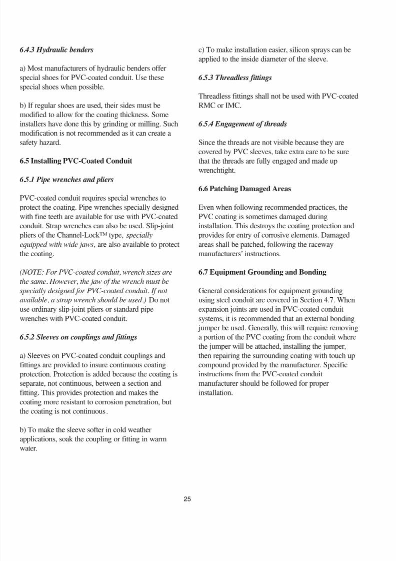
8/9/2019 Conduit Guide
http://slidepdf.com/reader/full/conduit-guide 28/3425
6.4.3 Hydraulic benders
a) Most manufacturers of hydraulic benders offer
special shoes for PVC-coated conduit. Use these
special shoes when possible.
b) If regular shoes are used, their sides must be
modified to allow for the coating thickness. Some
installers have done this by grinding or milling. Such
modification is not recommended as it can create a
safety hazard.
6.5 Installing PVC-Coated Conduit
6.5.1 Pipe wrenches and pliers
PVC-coated conduit requires special wrenches toprotect the coating. Pipe wrenches specially designed
with fine teeth are available for use with PVC-coated
conduit. Strap wrenches can also be used. Slip-joint
pliers of the Channel-Lock™ type, specially
equipped with wide jaws, are also available to protect
the coating.
(NOTE: For PVC-coated conduit, wrench sizes are
the same. However, the jaw of the wrench must be
specially designed for PVC-coated conduit. If not
available, a strap wrench should be used.) Do not
use ordinary slip-joint pliers or standard pipe
wrenches with PVC-coated conduit.
6.5.2 Sleeves on couplings and fittings
a) Sleeves on PVC-coated conduit couplings and
fittings are provided to insure continuous coating
protection. Protection is added because the coating is
separate, not continuous, between a section and
fitting. This provides protection and makes thecoating more resistant to corrosion penetration, but
the coating is not continuous.
b) To make the sleeve softer in cold weather
applications, soak the coupling or fitting in warm
water.
c) To make installation easier, silicon sprays can be
applied to the inside diameter of the sleeve.
6.5.3 Threadless fittings
Threadless fittings shall not be used with PVC-coatedRMC or IMC.
6.5.4 Engagement of threads
Since the threads are not visible because they are
covered by PVC sleeves, take extra care to be sure
that the threads are fully engaged and made up
wrenchtight.
6.6 Patching Damaged Areas
Even when following recommended practices, the
PVC coating is sometimes damaged during
installation. This destroys the coating protection and
provides for entry of corrosive elements. Damaged
areas shall be patched, following the raceway
manufacturers’ instructions.
6.7 Equipment Grounding and Bonding
General considerations for equipment grounding
using steel conduit are covered in Section 4.7. When
expansion joints are used in PVC-coated conduit
systems, it is recommended that an external bonding
jumper be used. Generally, this will require removing
a portion of the PVC coating from the conduit where
the jumper will be attached, installing the jumper,
then repairing the surrounding coating with touch up
compound provided by the manufacturer. Specific
instructions from the PVC-coated conduit
manufacturer should be followed for proper
installation.

8/9/2019 Conduit Guide
http://slidepdf.com/reader/full/conduit-guide 29/34
Threading as a method of joining steel conduit has
proven to be a sound and dependable method through
decades of service. Some major advantages of
threaded joints are:
1. Simple hand tools can be used to dismantle andreplace sections of existing conduit systems.
2. Conduit can be threaded in the shop or on the job.
3. It is a safe method to use for installations in
hazardous locations.
4. When properly cut and made up, a threaded joint
retains the maximum wall strength by minimizing the
number of threads outside the coupling or fitting.
Successful threading requires close attention to all of
the details. The threading operation is simple, yet
precision is the key. The correct dies must be selected
for the conduit being threaded and the dies must be
sharp. A proper cutting lubricant must be used. Both
manual and power driven threading equipment are
available. In general, the nominal length of thread has
been cut when the front surfaces of the thread chasers
are flush with the end of the conduit. For all conduit
sizes, the threads are cut at an angle of 60 degree (the
angle included between the thread flanks). The thread
tapers 1 in 16 or 3/4 inch per foot on diameter.
A.1 Changing Dies
The necessary procedures for changing threading dies
are dependent on the specific threader being used. To
provide good workmanship, be sure to refer to the
manufacturer’s instructions.
Make certain that the machine and die head are clean.If chips are allowed to accumulate in the machine
components, problems will result.
Occasionally disassemble the die head and remove
any accumulation of foreign material. This practice
will increase the life of the die head and promote
better threads. When cutting threads, occasionally
check the condition of the dies. Make certain the dies
are not getting dull and that conduit material is not
fusing or welding to the cutting edges. If a problem
persists with the threads that are being cut, carefully
look at the threads. If the leading flank of a thread i
deformed, it probably is caused by something
different than if the receding flank is deformed. If
only the first few threads are deformed, the problemis different than if the deformation exists over the fu
length.
A.2 Some Causes of Common Threading
Problems
TORN THREADS:
(1) Improper cutting fluid
(2) Poor cutting fluid flow
(3) Dies are not ground for material being cut
(4) Dies are worn(5) Speed is too fast
(6) Material is too hard
WAVY THREADS:
(1) Dies are not ground for material being cut
(2) Dies are too tight in the die head
(3) Not enough bearing.
DIES CHIPPING ON TEETH:
(1) Improper cutting fluid
(2) The material is too hard
(3) Poor cutting fluid flow
(4) Speed is too fast.
METAL FUSING TO DIES:
(1) Improper cutting fluid
(2) Poor cutting fluid flow
(3) Speed is too fast
(4) Dies are dull.
DIES WEAR OUT QUICKLY:(1) Improper cutting fluid
(2) Speed is too fast.
SQUEALING DURING CUTTING:
(1) Improper cutting fluid
(2) Poor cutting fluid flow.
RAGGED OR CHATTERED THREADS:
(1) Dies are getting worn out and are dull.
26
ANNEX A: Threading Conduit

8/9/2019 Conduit Guide
http://slidepdf.com/reader/full/conduit-guide 30/34

8/9/2019 Conduit Guide
http://slidepdf.com/reader/full/conduit-guide 31/3428
This table shows examples of calculations from the GEMI (Grounding and ElectroMagnetic Interference)
analysis software program.
Reprinted from Soares Book on Bonding and Grounding , 10th edition, by permission of International
Association of Electrical Inspectors.
Maximum length of steel conduit/EMT that may safely be used as an equipment-grounding circuitconductor. Based on a ground-fault current of 400% of the overcurrent device rating.
Circuit 120 volts to ground; 40 volts drop at the point of fault. Ambient temperature 25°C.
Maximum Maximum For Copper and AluminumLength of Length of
Run Run Fault(in feet) (in feet) Clearing
Copper using Aluminum using Overcurrent CurrentEquipment Copper Copper Equipment Aluminum Aluminum Device 400% O.C.Grounding Circuit Equipment Grounding Circuit Equipment Rating DeviceConductor AWG Ground Conductor AWG Grounding Amperes Rating
AWG Size*** Conductors Conductor AWG Size*** Conductors Conductor 75°C** Amperes
14 14 253 12 12 244 15 6012 12 300 10 12 226 20 8010 10 319 8 8 310 30 120
10 8 294 8 8 232 40 16010 6 228 8 4 221 60 2408 3 229 6 1 222 100 400
6 3/0 201 4 250 kcm 195 200 8004 350 kcm 210 2 500 kcm 204 300 12003 600 kcm 195 1 900 kcm 192 400 1600
2 2-4/0 160 1/0 2-400 kcm 163 500 20001 2-300 kcm 160 2/0 2-500 kcm 161 600 2400
1/0 3-300 kcm 134 3/0 3-400 kcm 131 800 3200
2/0 4-250 kcm 114 4/0 4-400 kcm 115 1000 40003/0 4-300 kcm 106 250 kcm 4-500 kcm 107 1200 48004/0 4-600 kcm 93 350 kcm 4-900 kcm 97 1600 6400
250 kcm 5-600 kcm 78 400 kcm 5-800 kcm 79 2000 8,000350 kcm 6-600 kcm * 600 kcm 6-900 kcm * 2500 10,000400 kcm 8-500 kcm * 600 kcm 8-750 kcm * 3000 15,000
500 kcm 8-1000 kcm * 800 kcm 8-1500 kcm * 4000 16,000700 kcm 10-1000 kcm * 1200 kcm 10-1500 kcm * 5000 20,000800 kcm 12-1000 kcm * 1200 kcm 12-1500 kcm * 6000 24,000
*Calculations necessary** 60°C for 20- and 30-ampere devices*** Based on NEC Chapter 9, Table 8

8/9/2019 Conduit Guide
http://slidepdf.com/reader/full/conduit-guide 32/3429
* 60°C for 30- and 30-ampere devices
This table shows examples of calculations from the GEMI (Grounding and ElectroMagnetic Interference)
analysis software program.
Derived from Soares Book on Bonding and Grounding , 10th edition, by permission of InternationalAssociation of Electrical Inspectors.
Maximum length of steel conduit/EMT that may safely be used as an equipment-grounding circuitconductor. Based on a ground-fault current of 400% of the overcurrent device rating.
Circuit 120 volts to ground; 40 volts drop at the point of fault. Ambient temperature 25°C.
Maximum Maximum MaximumOvercurrent Fault Clearing Length Length Length
Device Rating Current 400% O.C. of of ofConductors Amperes Device Rigid IMC EMT
Trade Size AWG 75°C* Rating Amperes Run in feet Run in feet Run in feet
½ (16) 3-12 20 80 384 398 3954-10 30 120 364 383 358
¾ (21) 4-10 30 120 386 399 4044-8 50 200 334 350 332
1 (27) 4-8 50 200 350 362 3703-4 85 340 357 382 365
1 ¼ (35) 3-2 115 460 365 392 391
1 ½ (41) 3-1 130 520 377 402 4073-2/0 175 700 348 377 364
2 (53) 3-3/0 200 800 363 389 3903-4/0 230 920 347 375 367
2 ½ (63) 3-250 kcm 255 1020 356 368 406
3 (78) 3-350 kcm 310 1240 355 367 4043-500 kcm 380 1520 327 338 3703-600 kcm 420 1680 314 325 353
4 (103) 3-900 kcm 520 2080 310 320 3533-1000 kcm 545 2180 304 314 347

8/9/2019 Conduit Guide
http://slidepdf.com/reader/full/conduit-guide 33/34
This publication, when used in conjunction with
the National Electric Code® and steel conduit
manufacturers’ literature, provides sufficient
information to install steel conduit. The following
associations and publications may also provide
useful information:
National Fire Protection Association (NFPA)
One Batterymarch Park
P.O. Box 9101
Quincy, MA 02269-9101
Phone (617) 770-3000
www.nfpa.org
• NFPA 70™ (National Electrical Code®)
National Electrical Manufacturers Association
(NEMA)
1300 North 17th St., Suite 1847
Rosslyn, VA 22209
Phone: (703) 841-3200
www.nema.org
• NEMA FB 1 Fittings, Cast Metal Boxes,
and Conduit Bodies for Conduit and
Cable Assemblies
• NEMA FB 2.10 Selection and Installation
Guidelines for Fittings for use with Non-
Flexible Metallic Conduit or Tubing
Steel Tube Institute of North America (STINA)
Conduit Committee
2000 Ponce de Leon, Suite 600
Coral Gables, FL 33134
Phone: (305) 421-6326
www.steelconduit.org
• Annular Space Protection of Openings
Created by Penetrations of Tubular Steel
Conduit
• Modeling and Evaluation of Conduit
Systems for Harmonics and
Electromagnetic Fields
• Modeling and Testing of Steel EMT, IMC
and Rigid (GRC) Conduit
• GEMI (Grounding and Electromagnetic
Interference) Analysis Software
• “TechTalk Brochures”
• UL® and NEC ® Requirements for
Corrosion Protection of Steel Condu
and Electrical Metallic Tubing.
• Steel Conduit and EMT: Proven to
Meet the NEC ® Requirements for
Equipment Grounding.
International Code Council (ICC)
500 New Jersey Avenue, NW
Washington, DC 20001
Phone: (888) 422-7233
www.iccsafe.org
• International Building Code
30
ANNEX C: Reference Standards
8/9/2019 Conduit Guide
http://slidepdf.com/reader/full/conduit-guide 34/34
2000 Ponce de Leon, Suite 600, Coral Gables, FL 33134 • Tel: (305) 421-6326E-mail: [email protected] • Website: http://www.steeltubeinstitute.org
Steel Conduit Website: http://www.steelconduit.org
Steel Conduit ProducersAllied Tube & Conduit
16100 S. Lathrop Avenue
Harvey, IL 60426
Telephone: (708) 339-1610
Fax: (708) 339-9827
www.alliedeg.com
Picoma Industries
330 East Ninth Street
Waynesboro, PA 17268
Telephone: (800) 742-6621
Fax: (717) 762-0948
www.picoma.com/
Republic Conduit
7301 Logistics Drive
Louisville, KY 40258Telephone: (800) 840-8823
Fax: (502) 995-5873
www.republicconduit.com
Western Tube and Conduit Company
P.O. Box 2720
Long Beach, CA 90801-2720
Telephone: (310) 537-6300
Fax: (310) 604-9785
www.westerntube.com
Wheatland Tube Company
1 Council Avenue P.O. Box 0608
Wheatland, PA 16161-0608
Telephone: (800) 257-8182
Fax: (724) 346-8182
www.wheatland.com