Embed Size (px)
Citation preview
Condor XL
INSTRUCTIONS FOR USE / INSTRUCCIONES DE USOAdvance Models:56110000(LPG/48”), 56110001(Petrol/48”), 56110002(Diesel/48”), 56110003(LPG/60”), 56110004(Petrol/60”), 56110005(Diesel/60”)56110006(LPG/62”), 56110007(Petrol/62”), 56110008(Diesel/62”), 56110009(LPG/67”), 56110010(Petrol/67”), 56110015(Diesel/67”)56111035(LPG-AXP/48”), 56111036(Petrol-AXP/48”), 56111037(Diesel-AXP/48”)56111038(LPG-AXP/60”), 56111039(Petrol-AXP/60”), 56111040(Diesel-AXP/60”)56111041(LPG-AXP/62”), 56111042(Petrol-AXP/62”), 56111043(Diesel-AXP/62”)56111044(LPG-AXP/67”), 56111045(Petrol-AXP/67”), 56111046(Diesel-AXP/67”)
3/09 revised 4/09 Form No. 56041705
A-EnglishB-Español
A-2 / ENGLISH
A-2 - FORM NO. 56041705 - Condor XL™
TABLE OF CONTENTS PAGEIntroduction ........................................................................................... A-3Cautions and Warnings ........................................................................ A-4Consignes de prudence et de sécurité ................................................. A-5Know Your Machine .....................................................................A-6 – A-9Prepare the Machine for UseGeneral Information ............................................................................ A-10Pre-operational Checklist ........................................................A-11 – A-12 Hydraulic Oil ..................................................................................... A-11 Engine Oil ......................................................................................... A-11 Engine Coolant ................................................................................. A-12 Engine Air Filter ................................................................................ A-12 Fuel ................................................................................................... A-12Install the Brushes .............................................................................. A-13Filling the Solution Tank ...................................................................... A-14Operating the MachineStarting the Engine ............................................................................. A-15Detergent (AXP) System .........................................................A-16 – A-17Scrubbing ................................................................................A-18 – A-19Wet Vacuuming .................................................................................. A-18
After Using the MachineAfter Use ............................................................................................. A-20Shutting Down the Engine .................................................................. A-20
MaintenanceMaintenance Schedule ....................................................................... A-20Lubricating the Machine ..........................................................A-20 – A-21Side Broom Maintenance ................................................................... A-22Squeegee Maintenance ...................................................................... A-23Squeegee Adjustment ........................................................................ A-23Side Skirt Maintenance ....................................................................... A-24Debris Hopper Maintenance ............................................................... A-25Troubleshooting .......................................................................A-26 – A-27Technical Specifi cations ..................................................................... A-28
ENGLISH / A-3
FORM NO. 56041705 - Condor XL™ - A-3
INTRODUCTIONThis manual will help you get the most from your Advance Rider Scrubber. Read it thoroughly before operating the machine.Note: Bold numbers in parentheses indicate an item illustrated on pages 6 – 9.
PARTS AND SERVICERepairs, when required, should be performed by your Authorized Advance Service Center, who employs factory trained service personnel, and maintains an inventory of Advance original replacement parts and accessories.Call the ADVANCE DEALER named below for repair parts or service. Please specify the Model and Serial Number when discussing your machine.
(Dealer, affi x service sticker here.)
NAME PLATEThe Model Number and Serial Number of your machine are shown on the Nameplate on the machine. This information is needed when ordering repair parts for the machine. Use the space below to note the Model Number and Serial Number of your machine for future reference.
MODEL NUMBER _______________________________________________________
SERIAL NUMBER ______________________________________________________
UN-CRATINGUpon delivery, carefully inspect the shipping crate and the machine for damage. If damage is evident, save all parts of the shipping crate so that they can be inspected by the trucking company that delivered the machine. Contact the trucking company immediately to fi le a freight damage claim.1 After removing the crate, remove the wooden blocks next to the wheels.2 Check the engine oil and coolant levels.3 Check the hydraulic oil level.4 Read the instructions in the Preparing the Machine For Use section of this manual, then fi ll the fuel tank.6 Place a ramp next to the front end of the pallet.7 Read the instructions in the Operating Controls and Operating the Machine sections of this manual and start the engine. Slowly drive the machine forward
down the ramp to the fl oor. Keep your foot lightly on the brake pedal until the machine is off the pallet.
CAUTION!Use extreme CAUTION when operating this machine. Be certain that you are thoroughly familiar with all operating instructions before using this machine. If you have any questions, contact your supervisor or your local Advance Industrial Dealer.If the machine malfunctions, do not try to correct the problem unless your supervisor directs you to do so. Have a qualifi ed company mechanic or an authorized Advance Dealer service person make any necessary corrections to the equipment.Use extreme care when working on this machine. Loose clothing, long hair, and jewelry can get caught in moving parts. Turn the Key Ignition Switch OFF and remove the key before servicing the machine. Use good common sense, practice good safety habits and pay attention to the yellow decals on this machine.Drive the machine slowly on inclines. Use the Brake Pedal (23) to control machine speed while descending inclines. DO NOT turn the machine on an incline; drive straight up or down.The maximum rated incline for sweeping and scrubbing is 10.5%(6°). The maximum rated incline during transport is 16%(9°).
A-4 / ENGLISH
A-4 - FORM NO. 56041705 - Condor XL™
CAUTIONS AND WARNINGSSYMBOLSAdvance uses the symbols below to signal potentially dangerous conditions. Always read this information carefully and take the necessary steps to protect personnel and property.
DANGER!Is used to warn of immediate hazards that will cause severe personal injury or death.
WARNING!Is used to call attention to a situation that could cause severe personal injury.
CAUTION!Is used to call attention to a situation that could cause minor personal injury or damage to the machine or other property.
Read all instructions before using.
GENERAL SAFETY INSTRUCTIONSSpecifi c Cautions and Warnings are included to warn you of potential danger of machine damage or bodily harm.
DANGER!* This machine emits exhaust gases (carbon monoxide) that can cause serious injury or death, always provide adequate
ventilation when using machine.
WARNING!* This machine shall be used only by properly trained and authorized persons.* While on ramps or inclines, avoid sudden stops when loaded. Avoid abrupt sharp turns. Use low speed down hills. Clean only
while ascending (driving up) the ramp.* To avoid hydraulic oil injection or injury always wear appropriate clothing and eye protection when working with or near hydraulic
system.* Turn the key switch (50) off (O) and disconnect the batteries before servicing electrical components.* Never work under a machine without safety blocks or stands to support the machine.* Do not dispense fl ammable cleaning agents, operate the machine on or near these agents, or operate in areas where fl ammable
liquids exist.* Do not clean this machine with a pressure washer.
CAUTION!* This machine is not approved for use on public paths or roads.* This machine is not suitable for picking up hazardous dust.* Use care when using scarifi er discs and grinding stones. Advance will not be held responsible for any damage to fl oor surfaces
caused by scarifi ers or grinding stones.* When operating this machine, ensure that third parties, particularly children, are not endangered.* Before performing any service function, carefully read all instructions pertaining to that function.* Do not leave the machine unattended without fi rst turning the key switch (50) off (O), removing the key and applying the parking
brake.* Turn the key switch (50) off (O) before changing the brushes, and before opening any access panels.* Take precautions to prevent hair, jewelry, or loose clothing from becoming caught in moving parts.* Use caution when moving this machine in below freezing temperature conditions. Any water in the solution or recovery tanks or
in the hose lines could freeze.* Before use, all doors and hoods should be properly latched.
SAVE THESE INSTRUCTIONS
ENGLISH / A-5
FORM NO. 56041705 - Condor XL™ - A-5
CONSIGNES DE PRUDENCE ET DE SECURITESYMBOLESAdvance utilise les symboles reproduits ci-dessous pour attirer l’attention de l’opérateur sur des situations potentiellement dangereuses. Il est donc conseillé de lire attentivement ces indications et de prendre les mesures adéquates en vue de protéger le personnel et le matériel.
DANGER !Ce symbole est utilisé pour mettre l’opérateur en garde contre les risques immédiats pouvant provoquer des dommages corporels graves, voire entraîner la mort.
ATTENTION !Ce symbole est utilisé pour attirer l’attention sur une situation susceptible d’entraîner des dommages corporels graves.
PRUDENCE !Ce symbole est utilisé pour attirer l’attention de l’opérateur sur une situation qui pourrait entraîner des dommages corporels minimes ou des dommages à la machine ou à d’autres équipements.
Lire toutes les instructions avant d’utiliser l’appareil.
CONSIGNES GENERALES DE SECURITELes consignes spécifi ques de prudence et de sécurité mentionnées ici ont pour but de vous informer de la survenance de tout risque de dommages matériels ou corporels.
DANGER !* Les gaz d’échappement (monoxyde de carbone) évacués par la machine peuvent entraîner de graves dommages corporels, voire la mort. Veillez donc
toujours à bénéfi cier d’une ventilation suffi sante lorsque vous utilisez la machine.
ATTENTION !* Cette machine ne pourra être utilisée que par du personnel parfaitement entraîné et dûment autorisé.* Evitez les arrêts subits lorsque la machine est chargée et se trouve sur des rampes ou des plans inclinés. Evitez les virages serrés. Adoptez une vitesse
réduite lorsque la machine est en descente. Ne nettoyez que lorsque la machine monte la pente.* Lorsque vous utilisez le système hydraulique ou travaillez à proximité de celui-ci, veillez à porter une tenue appropriée et des lunettes de protection afi n
d’éviter tout risque de blessures ou toute projection d’huile.* Positionnez la clé de contact sur (50) off (O) et déconnectez les batteries avant de procéder à l’entretien des composants électriques.* Ne travaillez jamais sous une machine sans y avoir placé, au préalable, des blocs de sécurité ou des étais destinés à soutenir la machine* Ne déversez pas d’agents nettoyants infl ammables, ne faites pas fonctionner la machine à proximité de ces agents ou d’autres liquides infl ammables.* Ne nettoyez pas cette machine avec un nettoyeur à pression.
PRUDENCE !* Cette machine n’est pas conçue pour une utilisation sur les chemins ou voies publiques.* Cette machine n’est pas conçue pour le ramassage des poussières dangereuses.* Faites extrêmement attention lorsque vous utilisez des disques de scarifi cateur et des meules. Advance ne pourra, en aucun cas, être tenu pour responsable
des dommages occasionnés à vos sols par ce type d’équipement.* Lors de l’utilisation de cette machine, assurez-vous que des tiers, et notamment des enfants, ne courent pas le moindre risque.* Avant de procéder à toute opération d’entretien, veuillez lire attentivement toutes les instructions qui s’y rapportent.* Ne laissez pas la machine sans surveillance sans avoir, au préalable, coupé le contact, enlevé la clé de contact (O) et tiré le frein à main.* Positionnez la clé de contact sur (50) off (O) avant de remplacer les brosses ou d’ouvrir tout panneau d’accès.* Prenez toutes les mesures nécessaires pour éviter que les cheveux, les bijoux ou les vêtements amples ne soient entraînés dans les parties mobiles de la
machine.* Faites attention lorsque vous déplacez cette machine dans un endroit où la température peut descendre sous 0°. Car l’eau contenue dans la solution, dans
les réservoirs de récupération ou dans les conduites risquerait de geler.* Avant utilisation, toutes les portes et capots doivent être correctement fermés.
CONSERVEZ SOIGNEUSEMENT CES INSTRUCTIONS
A-6 / ENGLISH
A-6 - FORM NO. 56041705 - Condor XL™
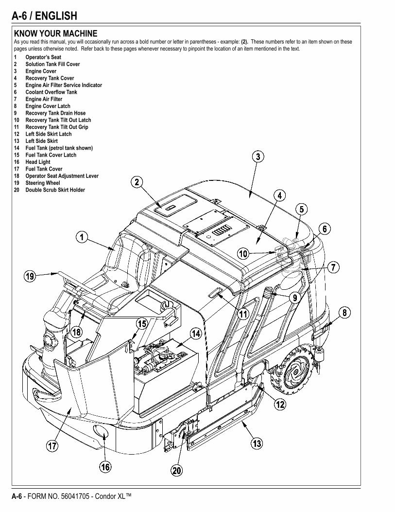
KNOW YOUR MACHINEAs you read this manual, you will occasionally run across a bold number or letter in parentheses - example: (2). These numbers refer to an item shown on these pages unless otherwise noted. Refer back to these pages whenever necessary to pinpoint the location of an item mentioned in the text.1 Operator’s Seat2 Solution Tank Fill Cover3 Engine Cover4 Recovery Tank Cover5 Engine Air Filter Service Indicator6 Coolant Overfl ow Tank7 Engine Air Filter8 Engine Cover Latch9 Recovery Tank Drain Hose10 Recovery Tank Tilt Out Latch11 Recovery Tank Tilt Out Grip12 Left Side Skirt Latch13 Left Side Skirt14 Fuel Tank (petrol tank shown)15 Fuel Tank Cover Latch16 Head Light17 Fuel Tank Cover18 Operator Seat Adjustment Lever19 Steering Wheel20 Double Scrub Skirt Holder
ENGLISH / A-7
FORM NO. 56041705 - Condor XL™ - A-7
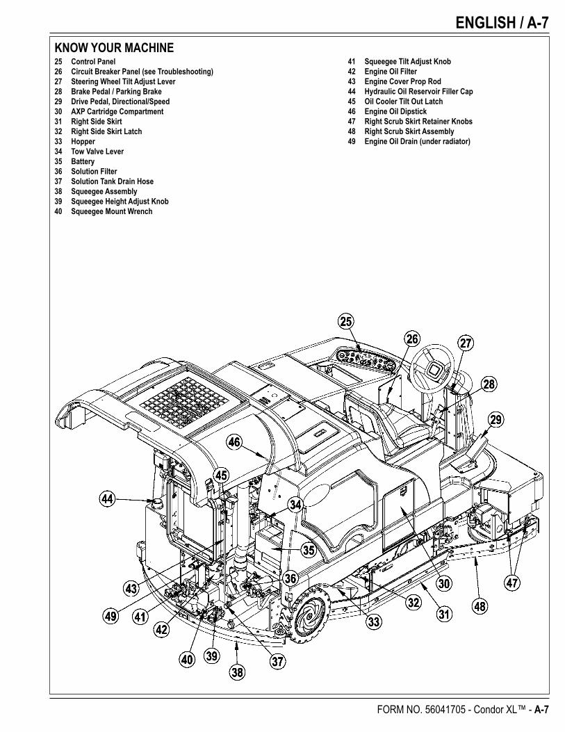
KNOW YOUR MACHINE25 Control Panel26 Circuit Breaker Panel (see Troubleshooting)27 Steering Wheel Tilt Adjust Lever28 Brake Pedal / Parking Brake29 Drive Pedal, Directional/Speed30 AXP Cartridge Compartment31 Right Side Skirt32 Right Side Skirt Latch33 Hopper34 Tow Valve Lever35 Battery36 Solution Filter37 Solution Tank Drain Hose38 Squeegee Assembly39 Squeegee Height Adjust Knob40 Squeegee Mount Wrench
41 Squeegee Tilt Adjust Knob42 Engine Oil Filter43 Engine Cover Prop Rod44 Hydraulic Oil Reservoir Filler Cap45 Oil Cooler Tilt Out Latch46 Engine Oil Dipstick47 Right Scrub Skirt Retainer Knobs48 Right Scrub Skirt Assembly49 Engine Oil Drain (under radiator)
A-8 / ENGLISH
A-8 - FORM NO. 56041705 - Condor XL™
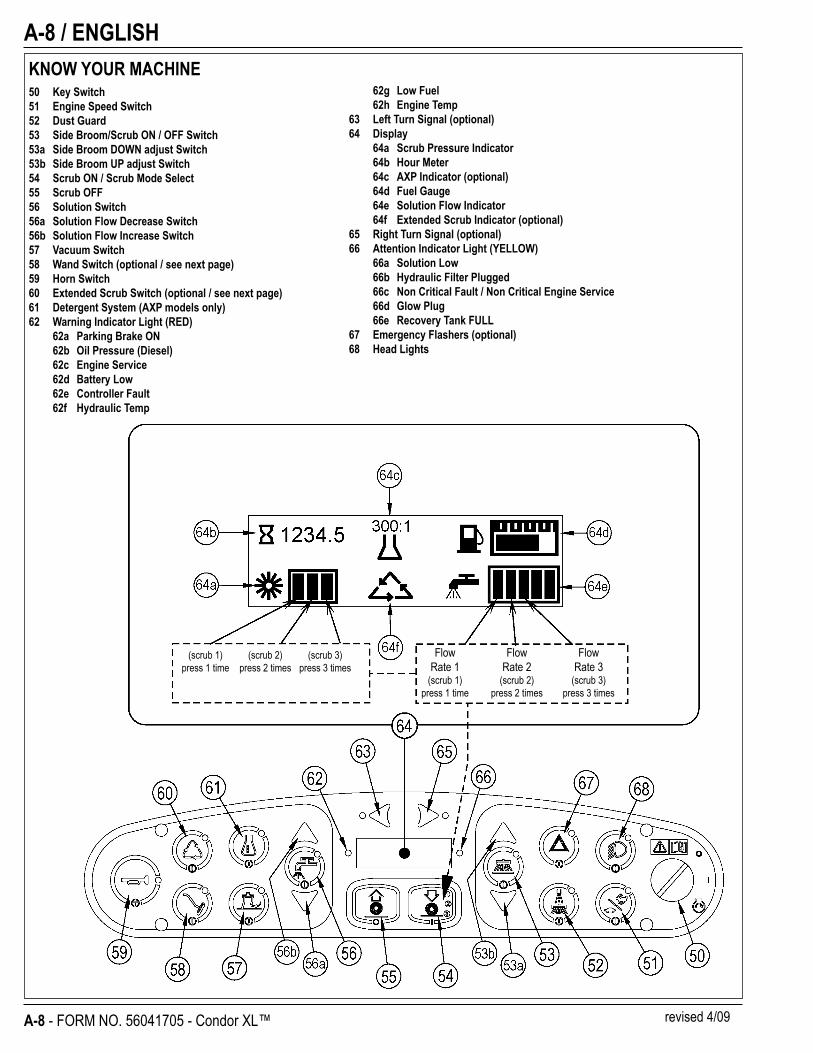
KNOW YOUR MACHINE50 Key Switch51 Engine Speed Switch52 Dust Guard53 Side Broom/Scrub ON / OFF Switch53a Side Broom DOWN adjust Switch53b Side Broom UP adjust Switch54 Scrub ON / Scrub Mode Select55 Scrub OFF56 Solution Switch56a Solution Flow Decrease Switch56b Solution Flow Increase Switch57 Vacuum Switch58 Wand Switch (optional / see next page)59 Horn Switch60 Extended Scrub Switch (optional / see next page)61 Detergent System (AXP models only)62 Warning Indicator Light (RED)
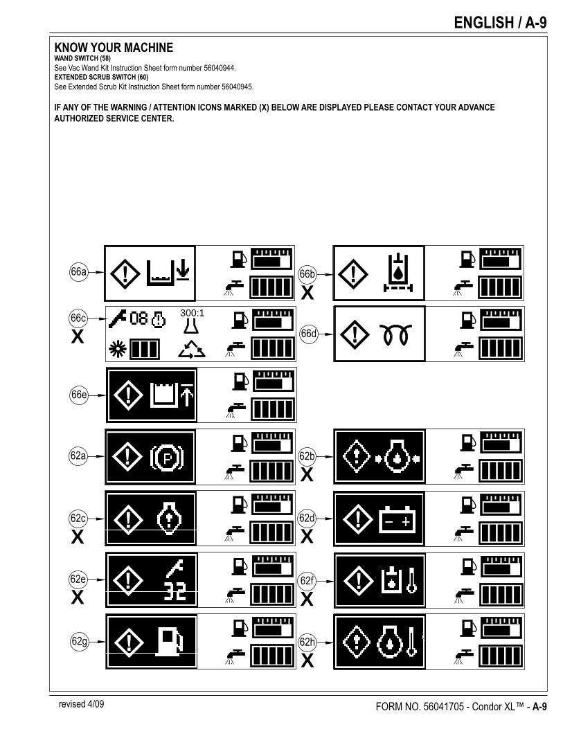
62a Parking Brake ON62b Oil Pressure (Diesel)62c Engine Service62d Battery Low62e Controller Fault62f Hydraulic Temp
Flow Flow Flow Rate 1 Rate 2 Rate 3 (scrub 1) (scrub 2) (scrub 3) press 1 time press 2 times press 3 times
62g Low Fuel62h Engine Temp
63 Left Turn Signal (optional)64 Display
64a Scrub Pressure Indicator64b Hour Meter64c AXP Indicator (optional)64d Fuel Gauge64e Solution Flow Indicator64f Extended Scrub Indicator (optional)
65 Right Turn Signal (optional)66 Attention Indicator Light (YELLOW)
66a Solution Low66b Hydraulic Filter Plugged66c Non Critical Fault / Non Critical Engine Service66d Glow Plug66e Recovery Tank FULL
67 Emergency Flashers (optional)68 Head Lights
(scrub 1) (scrub 2) (scrub 3) press 1 time press 2 times press 3 times
revised 4/09
ENGLISH / A-9
FORM NO. 56041705 - Condor XL™ - A-9
KNOW YOUR MACHINEWAND SWITCH (58)See Vac Wand Kit Instruction Sheet form number 56040944.EXTENDED SCRUB SWITCH (60)See Extended Scrub Kit Instruction Sheet form number 56040945.
IF ANY OF THE WARNING / ATTENTION ICONS MARKED (X) BELOW ARE DISPLAYED PLEASE CONTACT YOUR ADVANCE AUTHORIZED SERVICE CENTER.
300:1
66a 66b
66c
62a
66e
62c 62d
62e 62f
62g
66d
62h
62b
X
X
X
X
X
X
X
X
revised 4/09
A-10 / ENGLISH
A-10 - FORM NO. 56041705 - Condor XL™
JACKING THE MACHINE CAUTION!
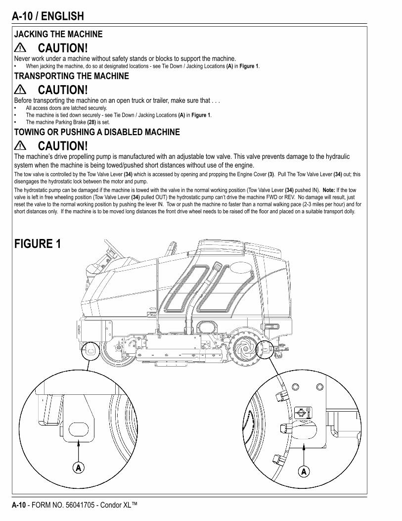
Never work under a machine without safety stands or blocks to support the machine.• When jacking the machine, do so at designated locations - see Tie Down / Jacking Locations (A) in Figure 1.
TRANSPORTING THE MACHINE CAUTION!
Before transporting the machine on an open truck or trailer, make sure that . . .• All access doors are latched securely.• The machine is tied down securely - see Tie Down / Jacking Locations (A) in Figure 1.• The machine Parking Brake (28) is set.
TOWING OR PUSHING A DISABLED MACHINE CAUTION!
The machine’s drive propelling pump is manufactured with an adjustable tow valve. This valve prevents damage to the hydraulic system when the machine is being towed/pushed short distances without use of the engine.The tow valve is controlled by the Tow Valve Lever (34) which is accessed by opening and propping the Engine Cover (3). Pull The Tow Valve Lever (34) out; this disengages the hydrostatic lock between the motor and pump.The hydrostatic pump can be damaged if the machine is towed with the valve in the normal working position (Tow Valve Lever (34) pushed IN). Note: If the tow valve is left in free wheeling position (Tow Valve Lever (34) pulled OUT) the hydrostatic pump can’t drive the machine FWD or REV. No damage will result, just reset the valve to the normal working position by pushing the lever IN. Tow or push the machine no faster than a normal walking pace (2-3 miles per hour) and for short distances only. If the machine is to be moved long distances the front drive wheel needs to be raised off the fl oor and placed on a suitable transport dolly.
FIGURE 1
ENGLISH / A-11
FORM NO. 56041705 - Condor XL™ - A-11
PRE-OPERATIONAL CHECKLISTBefore Each Use:* Inspect the machine for damage, oil or coolant leaks.* Squeeze the rubber dust cup on the Engine Air Filter (7) to release built-up dust.* Check the engine coolant level (6).* Check the engine oil level (46).* Check the hydraulic oil level (44).* Check the Fuel Gauge (64d) on the gasoline/petrol, and diesel models.* Check the Fuel Gauge located on the LP tank for LPG model.* Check the Air Filter Service Indicator (5).In the Driver’s Seat:* Be sure that you understand the operating controls and their functions.* Adjust the seat to allow easy reach of all controls.* Insert the Master Key and turn the Ignition Key Switch (50) to the ON position. Check for proper operation of the Horn (59), Hour Meter (64b) and Headlights
(68). Turn the Ignition Key Switch (50) OFF.* Check the Brake Pedal (28). The pedal should be fi rm and should not go all the way down. The latch should hold the pedal when applied. (Report all defects immediately to service personnel).Plan Your Cleaning in Advance:* Arrange long runs with a minimum of stopping or starting. * Allow 2-3” (5.08-7.62cm) of scrub path overlap to ensure complete coverage.* Avoid making sharp turns, bumping into posts, or scraping the side of the machine.
HYDRAULIC OILOpen and prop the Engine Cover (3) to access the hydraulic oil reservoir. Remove the Fill Cap (44) from the tank and look to the bottom of the fi ller screen. If the oil level is below the bottom of the fi ller screen, add 10W30 motor oil until the bottom of the fi ller screen is covered (oil level should not be higher than 1/2” (12.7mm) above the bottom of the fi ller screen). Change the oil if major contamination from a mechanical failure occurs.
ENGINE OIL – GASOLINE / PETROL & LPGCheck the engine oil level when the machine is parked on a level surface and the engine is cool. Change the engine oil after the fi rst 35 hours of operation and every 150 hours after that. Use any SF or SG rated oil meeting API specifi cations and suited to seasonal temperatures. Refer to the Engine System section for oil capacities and additional engine specifi cations. Replace the oil fi lter with every oil change. TEMPERATURE RANGE OIL WEIGHT Above 60° F (15° C) SAE 10W-30 Below 60° F (15° C) SAE 5W-30
ENGINE OIL - DIESELCheck the engine oil level when the machine is parked on a level surface and the engine is cool. Change the engine oil after the fi rst 35 hours of operation and every 150 hours after that. Use CF, CF-4 or CG-4 oil meeting API specifi cations and suited temperatures (*important reference the oil/fuel type note below for further diesel oil recommendations). Refer to the Engine System section for oil capacities and additional engine specifi cations. Replace the oil fi lter with every oil change. TEMPERATURE RANGE OIL WEIGHT Above 77 °F (25 °C) SAE 30 or 10W-30 32 °F to 77 °F (0 °C to 25 °C) SAE 20 or 10W-30 Below 32 °F (0 °C) SAE 10W or 10W-30* Diesel Lubricating Oil Note: With the emission control now in effect, the CF-4 and CG-4 lubricating oils have been developed for use with a low-sulfur fuel used in on-road vehicle
engines. When an off-road vehicle engine runs on a high-sulfur fuel, it is advisable to employ the CF, CD or CE lubricating oil with a high total base number. If the CF-4 or CG-4 lubricating oil is used with a high-sulfur fuel, change the lubricating oil at shorter intervals.
• Lubricating oil recommended when a low-sulfur or high-sulfur fuel is employed.
FuelLubricatingOil class
Low sulfur(0.5 % ≥) High sulfur Remarks
CF O O TBN ≥ 10CF-4 O XCG-4 O X
O : Recommended X : Not recommended
A-12 / ENGLISH
A-12 - FORM NO. 56041705 - Condor XL™
PRE-OPERATIONAL CHECKLISTENGINE COOLANT
CAUTION!Do not remove the radiator cap when the engine is hot.To check the engine coolant level, open and prop the Engine Cover (3) and observe the coolant level on the Coolant Recovery Tank (6). If the level is low add automotive type anti-freeze appropriately diluted for the environment. Clean the radiator and oil cooler exteriors by washing with low-pressure water or using compressed air every 30 hours. Service Note: The oil cooler tips out for easy cleaning.
ENGINE AIR FILTERCheck the Air Filter Service Indicator (5) before each use of the machine. Do not service the air fi lter unless the red fl ag is visible in the service indicator.
CAUTION!When servicing the engine air fi lter elements, use extreme care to prevent loose dust from entering the engine. Dust can severely damage the engine.The engine air fi lter contains a Primary (outer) and a Safety (inner) fi lter element. The Primary Element may be cleaned twice before being replaced. The Safety Element should be replaced every third time that the Primary Filter Element is replaced. Never attempt to clean the Inner Safety Element.To clean the Primary Filter Element, unsnap the 2 clips at the end of the air fi lter and remove the end housing. Pull the primary element out. Clean the element with compressed air (maximum pressure 100 psi) or wash it with water (maximum pressure 40 psi). DO NOT put the element back into the canister until it is completely dry.
FUEL WARNING!
• ALWAYS STOP THE ENGINE BEFORE FILLING THE FUEL TANK.• DO NOT SMOKE WHILE FILLING THE FUEL TANK.• FILL THE FUEL TANK IN A WELL-VENTILATED AREA.• DO NOT FILL THE FUEL TANK NEAR SPARKS OR OPEN FLAME.• USE ONLY THE FUEL SPECIFIED ON THE FUEL TANK DECAL.On machines with diesel and gasoline engines, a decal near the Fuel Tank (14) fi ller neck shows the proper fuel to use in the machine. Before removing the cap from the tank, wipe all dust and dirt from the cap and from the top of the tank to keep the fuel as clean as possible.On machines with propane engines, a decal near the tank gives specifi c information about the proper type of tank to be used on the machine.
DIESEL ENGINEFill the tank with Number 2 Diesel Fuel if the machine will be used in an area where the temperature is 30° Fahrenheit (0° Celsius) or higher. Use Number 1 Diesel Fuel if the machine will be used in an area where the temperature is below 30° Fahrenheit (0° Celsius).NOTE: If the diesel machine runs out of fuel completely, the fuel system must be bled before the engine can be re-started. To avoid this situation, fi ll the fuel tank when the fuel gauge indicates 1/4 tank. Fuel tank capacity is 11 gallons (42 liters).
GASOLINE / PETROL ENGINEFILL THE TANK WITH UNLEADED 87 OCTANE REGULAR GASOLINE. FUEL TANK CAPACITY IS 11 GALLONS (42 LITERS).Note: Reference the separately supplied engine manufacture’s maintenance and operator manual for more detailed engine specifi cation and service data.
LPG ENGINEMount a standard 33 lb. liquid withdrawal propane tank on the machine, connect the fuel hose and open the shutoff valve on the tank. Wear gloves when connecting or disconnecting the fuel hose. Shut the propane tank service valve OFF when the machine is not in use.
ENGLISH / A-13
FORM NO. 56041705 - Condor XL™ - A-13
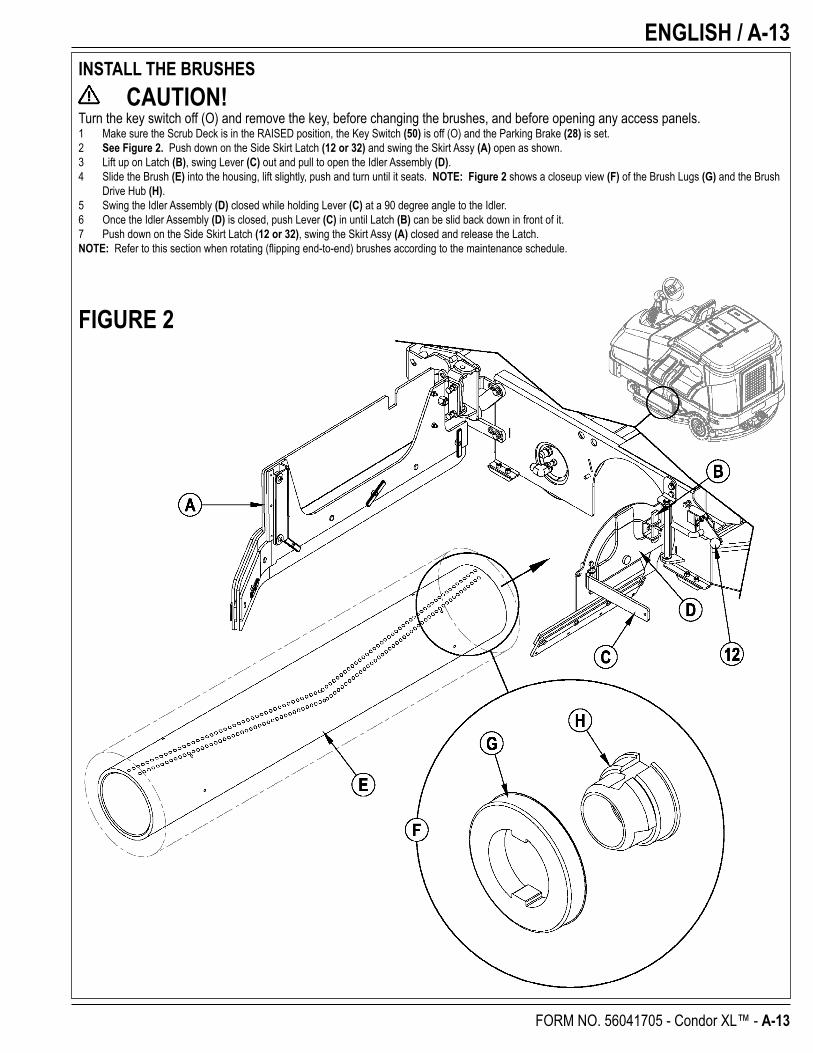
INSTALL THE BRUSHES CAUTION!
Turn the key switch off (O) and remove the key, before changing the brushes, and before opening any access panels.1 Make sure the Scrub Deck is in the RAISED position, the Key Switch (50) is off (O) and the Parking Brake (28) is set.2 See Figure 2. Push down on the Side Skirt Latch (12 or 32) and swing the Skirt Assy (A) open as shown.3 Lift up on Latch (B), swing Lever (C) out and pull to open the Idler Assembly (D).4 Slide the Brush (E) into the housing, lift slightly, push and turn until it seats. NOTE: Figure 2 shows a closeup view (F) of the Brush Lugs (G) and the Brush
Drive Hub (H).5 Swing the Idler Assembly (D) closed while holding Lever (C) at a 90 degree angle to the Idler.6 Once the Idler Assembly (D) is closed, push Lever (C) in until Latch (B) can be slid back down in front of it.7 Push down on the Side Skirt Latch (12 or 32), swing the Skirt Assy (A) closed and release the Latch.NOTE: Refer to this section when rotating (fl ipping end-to-end) brushes according to the maintenance schedule.
FIGURE 2
A-14 / ENGLISH
A-14 - FORM NO. 56041705 - Condor XL™
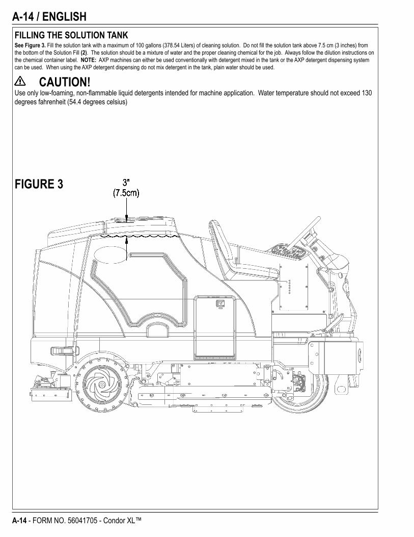
FILLING THE SOLUTION TANKSee Figure 3. Fill the solution tank with a maximum of 100 gallons (378.54 Liters) of cleaning solution. Do not fi ll the solution tank above 7.5 cm (3 inches) from the bottom of the Solution Fill (2). The solution should be a mixture of water and the proper cleaning chemical for the job. Always follow the dilution instructions on the chemical container label. NOTE: AXP machines can either be used conventionally with detergent mixed in the tank or the AXP detergent dispensing system can be used. When using the AXP detergent dispensing do not mix detergent in the tank, plain water should be used.
CAUTION!Use only low-foaming, non-fl ammable liquid detergents intended for machine application. Water temperature should not exceed 130 degrees fahrenheit (54.4 degrees celsius)
FIGURE 3
ENGLISH / A-15
FORM NO. 56041705 - Condor XL™ - A-15
OPERATING THE MACHINEThe Condor XL™ is a rider-type automatic fl oor scrubbing machine. It is designed to lay down cleaning solution, scrub the fl oor, and vacuum dry all in one pass.The controls on the Condor XL were designed with one touch operation in mind. For single pass scrubbing the user can simply depress one switch and all scrub functions on the machine will be activated.NOTE: Bold numbers in parentheses indicate an item illustrated on pages 6-9.NOTE!: MAKE SURE THE FOOT PEDAL IS IN THE NEUTRAL POSITION. THE ENGINE WILL NOT CRANK IF THE FOOT PEDAL IS NOT IN NEUTRAL.STARTING THE DIESEL ENGINE1 Turn the key switch (50) clockwise to the RUN (ON) position. The glow plugs will activate for 10 seconds as indicated by the attention indicator (66) and the
glow plug icon (66d) on the display. If the engine is already warm, turn the key switch to the start position to crank the engine. If the engine is cold, wait for the attention indicator and glow plug icon to turn off before cranking the engine. The engine should start immediately. If the engine does not start within 15 seconds release the key, wait for approximately one minute and repeat the above steps.
2 Let the engine run at IDLE speed for fi ve minutes before using the machine.3 Press the Engine Speed Switch (51) once to switch to FULL THROTTLE and move the machine around for two to three minutes at slow speed to warm up
the hydraulic system.
STARTING THE GASOLINE / PETROL ENGINE1 Turn the Ignition Key Switch (50) clockwise to the START position and release it as soon as the engine starts. If the engine does not start after cranking for
15 seconds, release the key, wait for 1 minute, then try again.2 Let the engine run at “IDLE” speed for 5 minutes before using the machine.3 Push the Engine Speed Switch (51) once to switch to “FULL THROTTLE” and move the machine around for 2 or 3 minutes at a slow speed to warm up the
hydraulic system.
STARTING THE LPG ENGINE1 Open the service valve on the LP fuel tank.2 Turn the Ignition Key Switch (50) clockwise to the START position and release it as soon as the engine starts. If the engine does not start after cranking for
15 seconds, release the key, wait for 1 minute, then try again.3 Let the engine run at “IDLE” speed for 5 minutes before using the machine.4 Push the Engine Speed Switch (51) once to switch to “FULL THROTTLE” and move the machine around for 2 or 3 minutes at a slow speed to warm up the
hydraulic system.ALWAYS operate the machine with the Engine Speed Switch at full throttle. Use the Drive Pedal (29) not the Engine Speed Switch (51) to control the speed of the machine. The speed of the machine will increase as the pedal is pushed closer to the fl oor. Do not press the Drive Pedal (29) until the engine has started.
Engine Speed Switch (51):There are three engine speed settings that can be selected by the engine speed switch (51) on the control panel.1 “Idle” (1200 RPM – Petrol / LPG) (1300 RPM – Diesel). Use for warm up and cool down. The engine speed switch light will be off.2 “Run” (2200 RPM). Use for transporting and most scrubbing operations. The engine speed light will be on.3 “Turbo” (2400 RPM). Use only for heavy engine load situations such as heavy scrubbing on inclines. The engine speed light will be on.4 To select between Idle and Run press and release the engine speed switch. 5 To select the Turbo speed, fi rst set the speed to Run. Then press and hold the engine speed switch for 2 seconds. To go back to Run speed, press the switch
again.6 The Condor XL has an automatic idle feature that will reduce the engine speed to idle when the foot pedal (29) has been in the neutral position for 20
seconds or more. The selected engine speed will automatically resume when the foot pedal is moved from neutral. If the engine speed switch (51) is pressed while in idle-override, the automatic idle feature will be temporarily disabled until the next time the foot pedal is moved from the neutral position. This can be useful during troubleshooting or if it is desired to let the machine run at full speed for warming up.
A-16 / ENGLISH
A-16 - FORM NO. 56041705 - Condor XL™
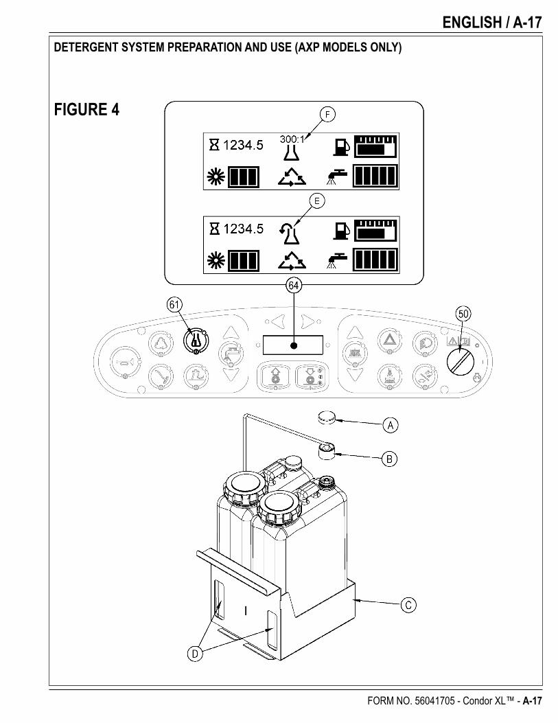
DETERGENT SYSTEM PREPARATION AND USE (AXP MODELS ONLY)Fill the detergent cartridge with a maximum of 2.2 gallons (8.32 Liters) of detergent. SERVICE NOTE: Remove the detergent cartridge from the detergent box prior to fi lling to avoid spilling detergent on the machine.It is recommended that a separate cartridge be used for each detergent you plan to use. The detergent cartridges have a white decal on them so you can write the detergent name on each cartridge to avoid mixing them up. When installing a new cartridge, remove the Cap (A) and place the cartridge in the detergent box. Install the Dry Break Cap (B) as shown.The system should be purged of previous detergent when switching to a different detergent. SERVICE NOTE: Move machine over fl oor drain before purging because a small amount of detergent will be dispensed in the process.To Purge When Changing Chemicals(SCRUB SYSTEM MUST BE OFF):1 Disconnect and remove the detergent cartridge.2 Turn the key switch (50) to the RUN (ON) position. Wait a few seconds for the start-up sequence to fi nish.3 Press and hold the detergent switch (61) for approximately 2 seconds. Release the switch when the chemical purge icon (E) appears on the display and the indicator on the
detergent switch (61) starts fl ashing. NOTE: Once activated the purge process takes at least 10 seconds. See illustration on next page for Detergent System indicators. Normally one purge cycle is adequate to purge the system.
To Purge Weekly(SCRUB SYSTEM MUST BE OFF):1 Disconnect and remove the detergent cartridge. Install and connect a Cartridge fi lled with clean hot water.2 Turn the key switch (50) to the RUN (ON) position. Wait a few seconds for the start-up sequence to fi nish.3 Press and hold the detergent switch (61) for approximately 2 seconds. Release the switch when the chemical purge icon (E) appears on the display and the indicator on the
detergent switch (61) starts fl ashing. NOTE: Once activated the purge process takes at least 10 seconds. See illustration on next page for Detergent System indicators. Normally one purge cycle is adequate to purge the system.
The Detergent Box (C) has Detergent Level Viewing Slots (D) for referencing the amount of detergent remaining in the cartridge(s). When the detergent level is nearing the bottom of this slot it is time to refi ll or replace the cartridge(s).
Detergent Ratio (SCRUB SYSTEM MUST BE ON):The detergent mixture rate may be adjusted by pressing and holding the detergent switch (61) for two seconds. Release the switch once the detergent switch light begins fl ashing. While the light is fl ashing, pressing and releasing the detergent switch will select the next detergent mixture. Once the desired mix is selected the detergent system will return to normal operation within three seconds.
The detergent mixture (F) will be displayed for approximately 10 seconds each time the scrub mode changes or each time the detergent switch is pressed.
Once set, the detergent fl ow rate automatically increases and decreases with the solution fl ow rate but the detergent ratio remains the same. If an operator would prefer the fl exibility of setting different detergent dilutions ratios for different solution fl ow rates this specifi c programming can be found in the service manual. During scrubbing, the detergent system can be turned off at any time by pressing the Detergent ON/OFF Switch (61) to allow scrubbing with water only. No detergent is dispensed until the scrub system is activated and the Drive Pedal (29) pushed forward.SERVICE NOTE: Follow the “To Purge Weekly” instructions above if the machine is going to be stored for an extended period of time or if you plan to discontinue use of the detergent (AXP) system.
revised 4/09
ENGLISH / A-17
FORM NO. 56041705 - Condor XL™ - A-17
DETERGENT SYSTEM PREPARATION AND USE (AXP MODELS ONLY)
FIGURE 4
A-18 / ENGLISH
A-18 - FORM NO. 56041705 - Condor XL™
SCRUBBING WARNING!
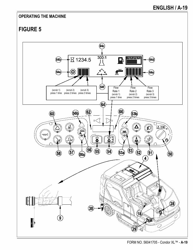
Be sure you understand the operator controls and their functions.While on ramps or inclines, avoid sudden stops when loaded. Avoid abrupt sharp turns. Use low speed down hills.To Scrub...Follow the instructions in preparing the machine for use section of this manual. Start the engine following the instructions in the appropriate “Starting the … Engine” section.1 See Figure 5. While seated on the machine, adjust the seat and steering wheel to a comfortable operating position using the adjustment controls (18 & 27).2 Release the Parking Brake (28). To transport the machine to the work area, apply even pressure with your foot on the front of the Drive Pedal (29) to go forward or the rear of
the pedal for reverse. Vary the pressure on the foot pedal to obtain the desired speed.3 Press the Solution Switch (56) and hold for 5 seconds to pre-wet the fl oor. NOTE: This will help prevent scarring of the fl oor surface when starting to scrub with dry brushes.
This must be done prior to pressing the Scrub ON Switch (54).4 Press the Scrub ON Switch (54) once for Light Scrub (1), twice for Medium Scrub (2) or three times for Heavy Scrub (3) mode. Both the solution fl ow and detergent (AXP
models) fl ow have 3 presets that coincide with the 3 scrub modes (see Display Panel (64)). The right side scrub brush pressure is also affected when pressing this switch.NOTE: The solution fl ow rate can be overridden simply by pressing the Solution Flow Decrease or Increase Switches (56a / 56b). Any subsequent scrub pressure adjustments will reset the solution fl ow rate to correspond with the scrub pressure.NOTE: The scrub, solution, vacuum, detergent (AXP models) and side broom(s) / brush systems are automatically enabled when the Scrub ON Switch (54) is pressed. Any individual system can be turned OFF or back ON by simply pressing its switch at any time during scrubbing. If you have installed the Extended Scrub Kit, it will not be automatically activated. You must press the Extended Scrub Switch (60) to activate this system. The Extended Scrub system will not turn ON until the water level in the recovery tank reaches a certain level and the clean solution has been used up.
5 When the Scrub ON Switch (54) is selected, the brushes, squeegee and side broom(s) / brush are automatically lowered to the fl oor. The scrub, solution, vacuum, detergent (AXP models) and side broom(s) / brush systems all start when the Drive Pedal (29) is activated.NOTE: When operating the machine in reverse the squeegee automatically raises and the solution fl ow will stop.
6 Begin scrubbing by driving the machine forward in a straight line at a normal walking speed and overlap each path by 2-3” (5.08-7.62cm). Adjust the machine speed and solution fl ow when necessary according to the condition of the fl oor.
The side broom height can be adjusted by pressing the Side Broom DOWN and UP Switches (53a/53b). The side broom(s) will return to the last used position each time the sweep system is turned on. The side brooms have a misting function (Dust Guard) (52) for use in dusty conditions. NOTE: The “Dust Guard” (52) comes on automatically with the Side Brooms (53) but can be turned OFF by pressing (52). NOTE: If equipped with Extended Scrub, the “Dust Guard” will shut off when the machine runs out of clean solution.
CAUTION!To avoid damaging the fl oor, keep the machine moving while the brushes are turning (the brushes will turn OFF after a 2 second delay when the drive pedal is placed in the neutral position).Raise scrub deck and side scrub brush, if so equipped, when crossing speed bumps. Do not attempt to operate the scrub deck or side brush in the down position when crossing speed bumps. Hydraulic pressure pushes down on the brushes and attempting to operate in the scrub mode over a speed bump can cause damage to the machine.7 When scrubbing, check behind the machine occasionally to see that all of the waste water is being picked up. If there is water trailing the machine, you may be dispensing too
much solution, the recovery tank may be full, or the squeegee tool may require adjustment.8 For extremely dirty fl oors, a one-pass scrubbing operation may not be satisfactory and a “double-scrub” operation may be required. This operation is the same as a one-pass
scrubbing except on the fi rst pass the squeegee is in the up position (press the Vacuum Switch (57) to raise the squeegee). This allows the cleaning solution to remain on the fl oor to work longer. The Side Skirts (13 & 31) can also be raised for double scrubbing if needed with the Skirt Holders (20). The fi nal pass is made over the same area, with the squeegee and skirts lowered to pick up the accumulated solution.
9 The recovery tank has a fl oat switch that causes ALL systems to turn OFF except the drive system when the recovery tank is full. When this fl oat switch is activated, the recovery tank must be emptied. The machine will not pick up water or scrub with the fl oat switch activated.
NOTE: The Attention Indicator Light (66) will light up YELLOW and the Recovery Full Icon (66e) will display when the fl oat switch is activated. If the control repeatedly gives a full indication when the tank is not full check to make sure the fl oat moves freely.
10 When the operator wants to stop scrubbing, press the Scrub OFF Switch (55) once. This will automatically stop the scrub brushes, side broom(s) / brush, solution fl ow and detergent fl ow. The scrub deck and side broom(s) / brush will raise up. The squeegee will raise up after a brief delay and the vacuum will stop after a brief delay (this is to allow any remaining water to be picked up without turning the vacuum back on).
11 Drive the machine to a designated waste water “DISPOSAL SITE” and empty the recovery tank. To empty, pull the Drain Hose (9) from its storage area, then remove the plug (hold the end of the hose above the water level in the tank to avoid sudden, uncontrolled fl ow of waste water). The Recovery Tank Drain Hose (9) can be squeezed to regulate the fl ow. Refi ll the solution tank and continue scrubbing.
NOTE: Make sure the Recovery Tank Cover (4) and the Recovery Tank Drain Hose (9) cap are properly seated or the machine will not pick-up water correctly.
SERVICE NOTE: Refer to the service manual for optional programmability.
revised 4/09
ENGLISH / A-19
FORM NO. 56041705 - Condor XL™ - A-19
OPERATING THE MACHINE
Flow Flow Flow Rate 1 Rate 2 Rate 3 (scrub 1) (scrub 2) (scrub 3) press 1 time press 2 times press 3 times
FIGURE 5
(scrub 1) (scrub 2) (scrub 3) press 1 time press 2 times press 3 times
A-20 / ENGLISH
A-20 - FORM NO. 56041705 - Condor XL™
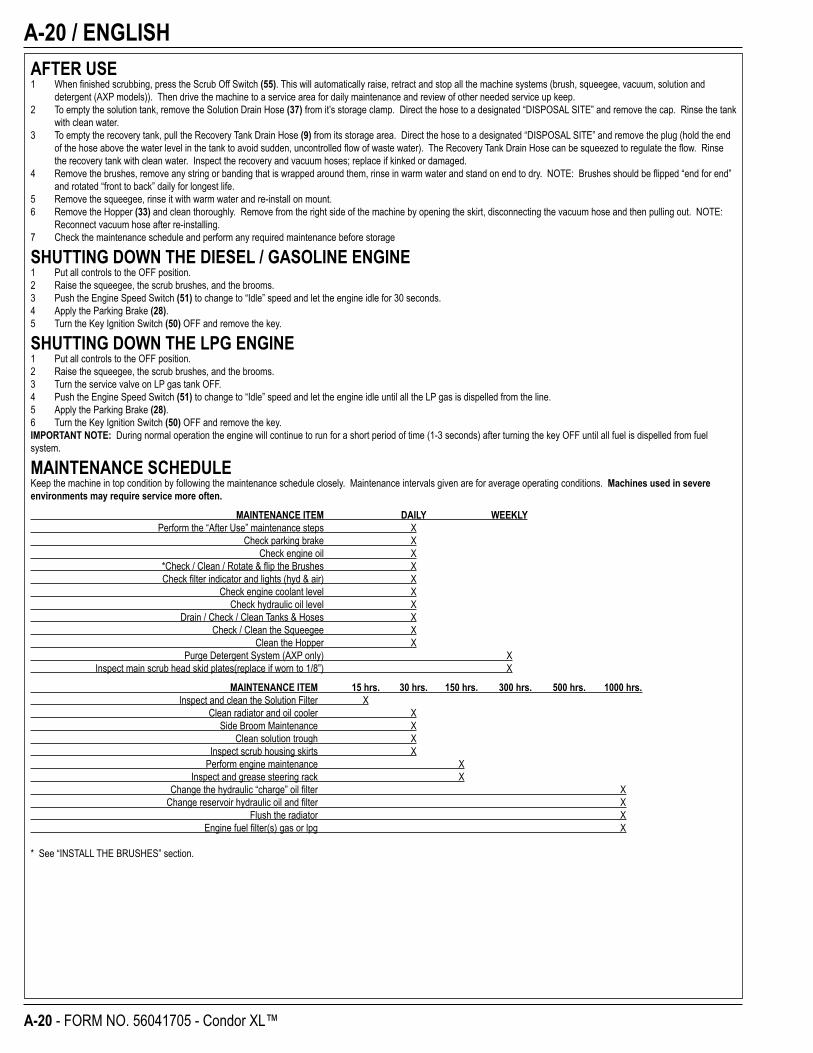
AFTER USE1 When fi nished scrubbing, press the Scrub Off Switch (55). This will automatically raise, retract and stop all the machine systems (brush, squeegee, vacuum, solution and
detergent (AXP models)). Then drive the machine to a service area for daily maintenance and review of other needed service up keep.2 To empty the solution tank, remove the Solution Drain Hose (37) from it’s storage clamp. Direct the hose to a designated “DISPOSAL SITE” and remove the cap. Rinse the tank
with clean water.3 To empty the recovery tank, pull the Recovery Tank Drain Hose (9) from its storage area. Direct the hose to a designated “DISPOSAL SITE” and remove the plug (hold the end
of the hose above the water level in the tank to avoid sudden, uncontrolled fl ow of waste water). The Recovery Tank Drain Hose can be squeezed to regulate the fl ow. Rinse the recovery tank with clean water. Inspect the recovery and vacuum hoses; replace if kinked or damaged.
4 Remove the brushes, remove any string or banding that is wrapped around them, rinse in warm water and stand on end to dry. NOTE: Brushes should be fl ipped “end for end” and rotated “front to back” daily for longest life.
5 Remove the squeegee, rinse it with warm water and re-install on mount.6 Remove the Hopper (33) and clean thoroughly. Remove from the right side of the machine by opening the skirt, disconnecting the vacuum hose and then pulling out. NOTE:
Reconnect vacuum hose after re-installing.7 Check the maintenance schedule and perform any required maintenance before storage
SHUTTING DOWN THE DIESEL / GASOLINE ENGINE1 Put all controls to the OFF position.2 Raise the squeegee, the scrub brushes, and the brooms.3 Push the Engine Speed Switch (51) to change to “Idle” speed and let the engine idle for 30 seconds.4 Apply the Parking Brake (28).5 Turn the Key Ignition Switch (50) OFF and remove the key.
SHUTTING DOWN THE LPG ENGINE1 Put all controls to the OFF position.2 Raise the squeegee, the scrub brushes, and the brooms.3 Turn the service valve on LP gas tank OFF.4 Push the Engine Speed Switch (51) to change to “Idle” speed and let the engine idle until all the LP gas is dispelled from the line.5 Apply the Parking Brake (28).6 Turn the Key Ignition Switch (50) OFF and remove the key.IMPORTANT NOTE: During normal operation the engine will continue to run for a short period of time (1-3 seconds) after turning the key OFF until all fuel is dispelled from fuel system.
MAINTENANCE SCHEDULEKeep the machine in top condition by following the maintenance schedule closely. Maintenance intervals given are for average operating conditions. Machines used in severe environments may require service more often.
MAINTENANCE ITEM DAILY WEEKLY Perform the “After Use” maintenance steps X Check parking brake X Check engine oil X *Check / Clean / Rotate & fl ip the Brushes X Check fi lter indicator and lights (hyd & air) X Check engine coolant level X Check hydraulic oil level X Drain / Check / Clean Tanks & Hoses X Check / Clean the Squeegee X Clean the Hopper X Purge Detergent System (AXP only) X Inspect main scrub head skid plates(replace if worn to 1/8”) X
MAINTENANCE ITEM 15 hrs. 30 hrs. 150 hrs. 300 hrs. 500 hrs. 1000 hrs. Inspect and clean the Solution Filter X Clean radiator and oil cooler X Side Broom Maintenance X Clean solution trough X Inspect scrub housing skirts X Perform engine maintenance X Inspect and grease steering rack X Change the hydraulic “charge” oil fi lter X Change reservoir hydraulic oil and fi lter X Flush the radiator X Engine fuel fi lter(s) gas or lpg X
* See “INSTALL THE BRUSHES” section.
ENGLISH / A-21
FORM NO. 56041705 - Condor XL™ - A-21
FIGURE 6
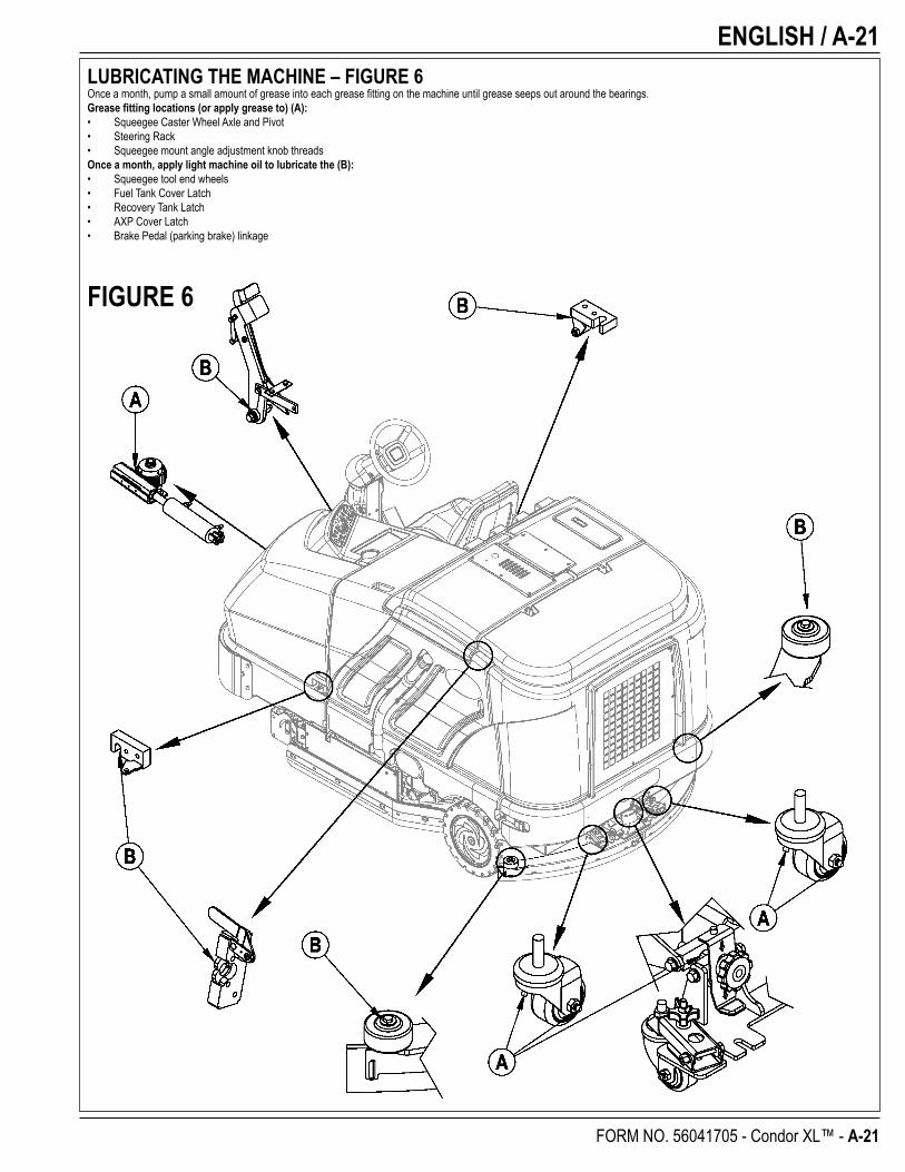
LUBRICATING THE MACHINE – FIGURE 6Once a month, pump a small amount of grease into each grease fi tting on the machine until grease seeps out around the bearings.Grease fi tting locations (or apply grease to) (A):• Squeegee Caster Wheel Axle and Pivot• Steering Rack• Squeegee mount angle adjustment knob threadsOnce a month, apply light machine oil to lubricate the (B):• Squeegee tool end wheels• Fuel Tank Cover Latch• Recovery Tank Latch• AXP Cover Latch• Brake Pedal (parking brake) linkage
A-22 / ENGLISH
A-22 - FORM NO. 56041705 - Condor XL™
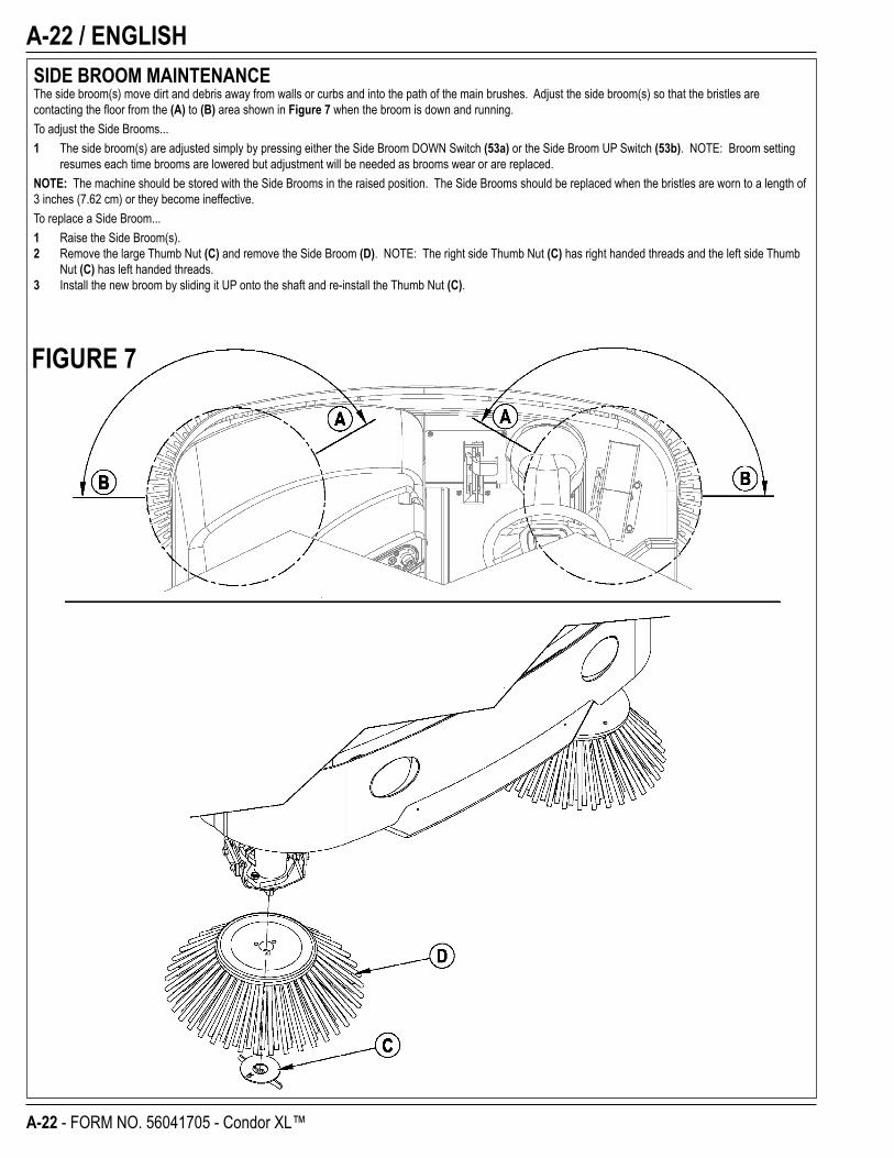
SIDE BROOM MAINTENANCEThe side broom(s) move dirt and debris away from walls or curbs and into the path of the main brushes. Adjust the side broom(s) so that the bristles are contacting the fl oor from the (A) to (B) area shown in Figure 7 when the broom is down and running.To adjust the Side Brooms...1 The side broom(s) are adjusted simply by pressing either the Side Broom DOWN Switch (53a) or the Side Broom UP Switch (53b). NOTE: Broom setting
resumes each time brooms are lowered but adjustment will be needed as brooms wear or are replaced.NOTE: The machine should be stored with the Side Brooms in the raised position. The Side Brooms should be replaced when the bristles are worn to a length of 3 inches (7.62 cm) or they become ineffective.To replace a Side Broom...1 Raise the Side Broom(s).2 Remove the large Thumb Nut (C) and remove the Side Broom (D). NOTE: The right side Thumb Nut (C) has right handed threads and the left side Thumb
Nut (C) has left handed threads.3 Install the new broom by sliding it UP onto the shaft and re-install the Thumb Nut (C).
FIGURE 7
ENGLISH / A-23
FORM NO. 56041705 - Condor XL™ - A-23
FIGURE 8
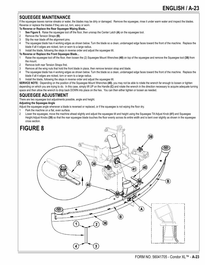
SQUEEGEE MAINTENANCEIf the squeegee leaves narrow streaks or water, the blades may be dirty or damaged. Remove the squeegee, rinse it under warm water and inspect the blades. Reverse or replace the blades if they are cut, torn, wavy or worn.To Reverse or Replace the Rear Squeegee Wiping Blade...1 See Figure 8. Raise the squeegee tool off the fl oor, then unsnap the Center Latch (A) on the squeegee tool.2 Remove the Tension Straps (B).3 Slip the rear blade off the alignment pins.4 The squeegee blade has 4 working edges as shown below. Turn the blade so a clean, undamaged edge faces toward the front of the machine. Replace the
blade if all 4 edges are nicked, torn or worn to a large radius.5 Install the blade, following the steps in reverse order and adjust the squeegee tilt.To Reverse or Replace the Front Squeegee Blade...1 Raise the squeegee tool off the fl oor, then loosen the (2) Squeegee Mount Wrenches (40) on top of the squeegee and remove the Squeegee tool (38) from
the mount.2 Remove both rear Tension Straps fi rst.3 Remove all the wing nuts that hold the front blade in place, then remove tension strap and blade. 4 The squeegee blade has 4 working edges as shown below. Turn the blade so a clean, undamaged edge faces toward the front of the machine. Replace the
blade if all 4 edges are nicked, torn or worn to a large radius.5 Install the blade, following the steps in reverse order and adjust the squeegee tilt.SERVICE NOTE: Depending on the position of the Squeegee Mount Wrenches (40), you may not be able to rotate the wrench far enough to loosen or tighten depending on which you are trying to do. In this case, simply lift UP on the Handle (C) and rotate the wrench in the direction necessary to acquire adequate turning space and then allow the wrench to drop back DOWN into place on the hex. You can then either tighten or loosen as needed.
SQUEEGEE ADJUSTMENTThere are two squeegee tool adjustments possible, angle and height.Adjusting the Squeegee AngleAdjust the squeegee angle whenever a blade is reversed or replaced, or if the squeegee is not wiping the fl oor dry.1 Park the machine on a fl at, even surface.2 Lower the squeegee, move the machine ahead slightly and adjust the squeegee tilt and height using the Squeegee Tilt Adjust Knob (41) and Squeegee
Height Adjust Knobs (39) so that the rear squeegee blade touches the fl oor evenly across its entire width and is bent over slightly as shown in the squeegee cross section.
A-24 / ENGLISH
A-24 - FORM NO. 56041705 - Condor XL™
SIDE SKIRT MAINTENANCE CAUTION!
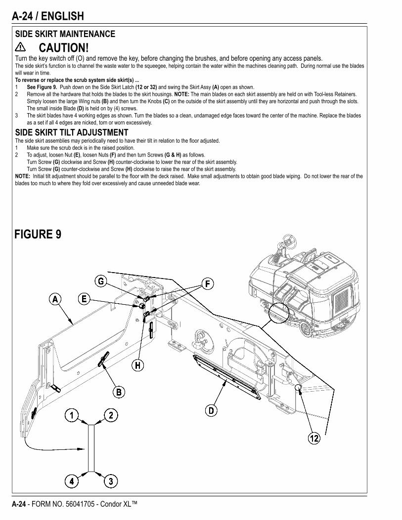
Turn the key switch off (O) and remove the key, before changing the brushes, and before opening any access panels.The side skirt’s function is to channel the waste water to the squeegee, helping contain the water within the machines cleaning path. During normal use the blades will wear in time.To reverse or replace the scrub system side skirt(s) ...1 See Figure 9. Push down on the Side Skirt Latch (12 or 32) and swing the Skirt Assy (A) open as shown.2 Remove all the hardware that holds the blades to the skirt housings. NOTE: The main blades on each skirt assembly are held on with Tool-less Retainers.
Simply loosen the large Wing nuts (B) and then turn the Knobs (C) on the outside of the skirt assembly until they are horizontal and push through the slots. The small inside Blade (D) is held on by (4) screws.
3 The skirt blades have 4 working edges as shown. Turn the blades so a clean, undamaged edge faces toward the center of the machine. Replace the blades as a set if all 4 edges are nicked, torn or worn excessively.
SIDE SKIRT TILT ADJUSTMENTThe side skirt assemblies may periodically need to have their tilt in relation to the fl oor adjusted.1 Make sure the scrub deck is in the raised position.2 To adjust, loosen Nut (E), loosen Nuts (F) and then turn Screws (G & H) as follows. Turn Screw (G) clockwise and Screw (H) counter-clockwise to lower the rear of the skirt assembly. Turn Screw (G) counter-clockwise and Screw (H) clockwise to raise the rear of the skirt assembly.NOTE: Initial tilt adjustment should be parallel to the fl oor with the deck raised. Make small adjustments to obtain good blade wiping. Do not lower the rear of the blades too much to where they fold over excessively and cause unneeded blade wear.
FIGURE 9
ENGLISH / A-25
FORM NO. 56041705 - Condor XL™ - A-25
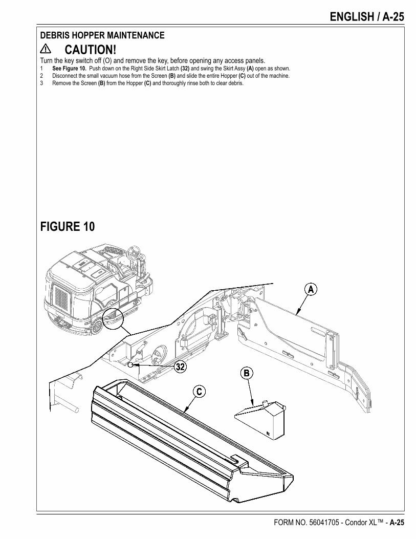
DEBRIS HOPPER MAINTENANCE CAUTION!
Turn the key switch off (O) and remove the key, before opening any access panels.1 See Figure 10. Push down on the Right Side Skirt Latch (32) and swing the Skirt Assy (A) open as shown.2 Disconnect the small vacuum hose from the Screen (B) and slide the entire Hopper (C) out of the machine.3 Remove the Screen (B) from the Hopper (C) and thoroughly rinse both to clear debris.
FIGURE 10
A-26 / ENGLISH
A-26 - FORM NO. 56041705 - Condor XL™
TROUBLESHOOTINGIf the possible causes listed below are not the source of trouble, it is a symptom of something more serious. Contact your Advance Service Center immediately for service.
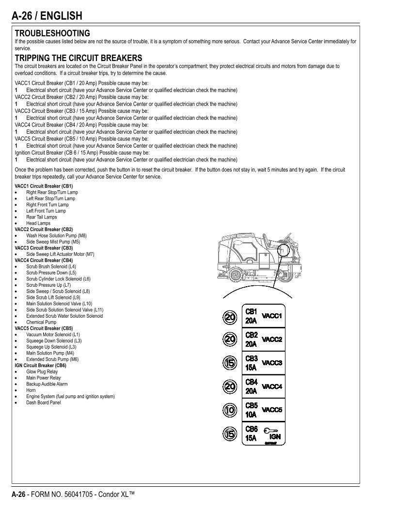
TRIPPING THE CIRCUIT BREAKERSThe circuit breakers are located on the Circuit Breaker Panel in the operator’s compartment; they protect electrical circuits and motors from damage due to overload conditions. If a circuit breaker trips, try to determine the cause.VACC1 Circuit Breaker (CB1 / 20 Amp) Possible cause may be:1 Electrical short circuit (have your Advance Service Center or qualifi ed electrician check the machine)VACC2 Circuit Breaker (CB2 / 20 Amp) Possible cause may be:1 Electrical short circuit (have your Advance Service Center or qualifi ed electrician check the machine)VACC3 Circuit Breaker (CB3 / 15 Amp) Possible cause may be:1 Electrical short circuit (have your Advance Service Center or qualifi ed electrician check the machine)VACC4 Circuit Breaker (CB4 / 20 Amp) Possible cause may be:1 Electrical short circuit (have your Advance Service Center or qualifi ed electrician check the machine)VACC5 Circuit Breaker (CB5 / 10 Amp) Possible cause may be:1 Electrical short circuit (have your Advance Service Center or qualifi ed electrician check the machine)Ignition Circuit Breaker (CB 6 / 15 Amp) Possible cause may be:1 Electrical short circuit (have your Advance Service Center or qualifi ed electrician check the machine)Once the problem has been corrected, push the button in to reset the circuit breaker. If the button does not stay in, wait 5 minutes and try again. If the circuit breaker trips repeatedly, call your Advance Service Center for service.VACC1 Circuit Breaker (CB1)
Right Rear Stop/Turn LampLeft Rear Stop/Turn LampRight Front Turn LampLeft Front Turn LampRear Tail LampsHead Lamps
VACC2 Circuit Breaker (CB2)Wash Hose Solution Pump (M8)Side Sweep Mist Pump (M5)
VACC3 Circuit Breaker (CB3)Side Sweep Lift Actuator Motor (M7)
VACC4 Circuit Breaker (CB4)Scrub Brush Solenoid (L4)Scrub Pressure Down (L5)Scrub Cylinder Lock Solenoid (L6)Scrub Pressure Up (L7)Side Sweep / Scrub Solenoid (L8)Side Scrub Lift Solenoid (L9)Main Solution Solenoid Valve (L10)Side Scrub Solution Solenoid Valve (L11)Extended Scrub Water Solution SolenoidChemical Pump
VACC5 Circuit Breaker (CB5)Vacuum Motor Solenoid (L1)Squeege Down Solenoid (L3)Squeege Up Solenoid (L3)Main Solution Pump (M4)Extended Scrub Pump (M6)
IGN Circuit Breaker (CB6)Glow Plug RelayMain Power RelayBackup Audible AlarmHornEngine System (fuel pump and ignition system)Dash Board Panel

ENGLISH / A-27
FORM NO. 56041705 - Condor XL™ - A-27
GENERAL MACHINE TROUBLESHOOTINGProblem Possible Cause Remedy
Poor water pick-up Worn or torn squeegee blades Reverse or replaceSqueegee out of adjustment Adjust so blades touch fl oor evenly
across entire widthRecovery tank full Empty recovery tankRecovery tank drain hose leak Secure drain hose cap or replaceRecovery tank cover gasket leak Replace gasket / Seat cover properlyDebris caught in squeegee Clean squeegee toolVacuum hose clogged Remove debrisUsing too much solution Reduce fl ow via control panel solution button
Poor scrubbing performance Worn brush Rotate or replace brushesWrong brush type Consult AdvanceWrong cleaning chemical Consult AdvanceMoving machine too fast Slow downNot using enough solution Increase fl ow via control panel solution buttonIncorrect detergent ratio Verify dilution setting if AXP equipped.
Inadequate solution fl owor no solution
Solution tank empty Fill solution tankSolution lines, valves, fi lter or trough clogged Flush lines, trough and clean solution fi lterSolution turned OFF Activate fl ow via control panel solution buttonSolution solenoid valve plugged or defective Clean or replace valve (see service manual)
Machine does not run Tripped 15 Amp (CB6) circuit breaker Check for electrical short circuit & resetMain system controller Check error fault codes
(see service manual)
No FWD/REV wheel drive Parking brake set Release parking brakeTowing valve in wrong position Set correctlyTripped circuit breakers Reset any tripped circuit breakers
Vacuum shuts off and display shows“FULL” when recovery tank is not full
Plugged squeegee hose Clear debrisVacuuming large amounts of waterat a high travel speed
Slow down or disable auto shut-off feature(see service manual)
No Detergent Flow (AXP models only) Empty detergent cartridge Fill detergent cartridgePlugged or kinked detergent fl ow line Purge system, straighten lines to
remove any kinksDry seal cap on detergent cartridge not sealed Reseat dry seal capDetergent pump wiringdisconnected or backwards
Connect or reconnect wiring
A-28 / ENGLISH
A-28 - FORM NO. 56041705 - Condor XL™
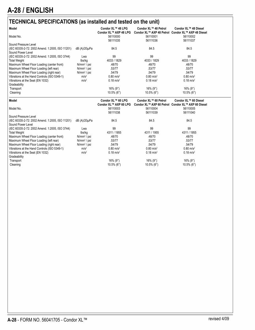
TECHNICAL SPECIFICATIONS (as installed and tested on the unit)Model Condor XL™ 48 LPG Condor XL™ 48 Petrol Condor XL™ 48 Diesel Condor XL™ AXP 48 LPG Condor XL™ AXP 48 Petrol Condor XL™ AXP 48 DieselModel No. 56110000 56110001 56110002 56111035 56111036 56111037Sound Pressure Level(IEC 60335-2-72: 2002 Amend. 1:2005, ISO 11201) dB (A)/20μPa 84.5 84.5 84.5Sound Power Level(IEC 60335-2-72: 2002 Amend. 1:2005, ISO 3744) Lwa 99 99 99Total Weight lbs/kg 4033 / 1829 4033 / 1829 4033 / 1829Maximum Wheel Floor Loading (center front) N/mm2 / psi .48/70 .48/70 .48/70Maximum Wheel Floor Loading (left rear) N/mm2 / psi .53/77 .53/77 .53/77Maximum Wheel Floor Loading (right rear) N/mm2 / psi .54/79 .54/79 .54/79Vibrations at the Hand Controls (ISO 5349-1) m/s2 0.80 m/s2 0.80 m/s2 0.80 m/s2
Vibrations at the Seat (EN 1032) m/s2 0.18 m/s2 0.18 m/s2 0.18 m/s2
Gradeability Transport 16% (9°) 16% (9°) 16% (9°) Cleaning 10.5% (6°) 10.5% (6°) 10.5% (6°)
Model Condor XL™ 60 LPG Condor XL™ 60 Petrol Condor XL™ 60 Diesel Condor XL™ AXP 60 LPG Condor XL™ AXP 60 Petrol Condor XL™ AXP 60 DieselModel No. 56110003 56110004 56110005 56111038 56111039 56111040Sound Pressure Level(IEC 60335-2-72: 2002 Amend. 1:2005, ISO 11201) dB (A)/20μPa 84.5 84.5 84.5Sound Power Level(IEC 60335-2-72: 2002 Amend. 1:2005, ISO 3744) Lwa 99 99 99Total Weight lbs/kg 4311 / 1955 4311 / 1955 4311 / 1955Maximum Wheel Floor Loading (center front) N/mm2 / psi .48/70 .48/70 .48/70Maximum Wheel Floor Loading (left rear) N/mm2 / psi .53/77 .53/77 .53/77Maximum Wheel Floor Loading (right rear) N/mm2 / psi .54/79 .54/79 .54/79Vibrations at the Hand Controls (ISO 5349-1) m/s2 0.80 m/s2 0.80 m/s2 0.80 m/s2
Vibrations at the Seat (EN 1032) m/s2 0.18 m/s2 0.18 m/s2 0.18 m/s2
Gradeability Transport 16% (9°) 16% (9°) 16% (9°) Cleaning 10.5% (6°) 10.5% (6°) 10.5% (6°)
revised 4/09
ENGLISH / A-29
FORM NO. 56041705 - Condor XL™ - A-29
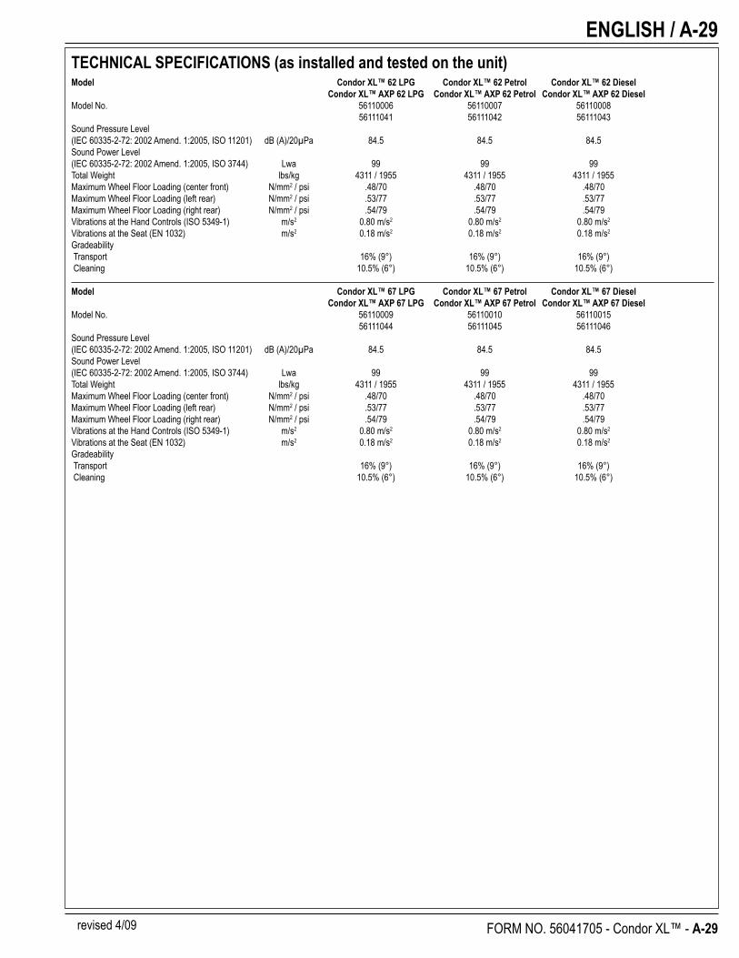
TECHNICAL SPECIFICATIONS (as installed and tested on the unit)Model Condor XL™ 62 LPG Condor XL™ 62 Petrol Condor XL™ 62 Diesel Condor XL™ AXP 62 LPG Condor XL™ AXP 62 Petrol Condor XL™ AXP 62 DieselModel No. 56110006 56110007 56110008 56111041 56111042 56111043Sound Pressure Level(IEC 60335-2-72: 2002 Amend. 1:2005, ISO 11201) dB (A)/20μPa 84.5 84.5 84.5Sound Power Level(IEC 60335-2-72: 2002 Amend. 1:2005, ISO 3744) Lwa 99 99 99Total Weight lbs/kg 4311 / 1955 4311 / 1955 4311 / 1955Maximum Wheel Floor Loading (center front) N/mm2 / psi .48/70 .48/70 .48/70Maximum Wheel Floor Loading (left rear) N/mm2 / psi .53/77 .53/77 .53/77Maximum Wheel Floor Loading (right rear) N/mm2 / psi .54/79 .54/79 .54/79Vibrations at the Hand Controls (ISO 5349-1) m/s2 0.80 m/s2 0.80 m/s2 0.80 m/s2
Vibrations at the Seat (EN 1032) m/s2 0.18 m/s2 0.18 m/s2 0.18 m/s2
Gradeability Transport 16% (9°) 16% (9°) 16% (9°) Cleaning 10.5% (6°) 10.5% (6°) 10.5% (6°)
Model Condor XL™ 67 LPG Condor XL™ 67 Petrol Condor XL™ 67 Diesel Condor XL™ AXP 67 LPG Condor XL™ AXP 67 Petrol Condor XL™ AXP 67 DieselModel No. 56110009 56110010 56110015 56111044 56111045 56111046Sound Pressure Level(IEC 60335-2-72: 2002 Amend. 1:2005, ISO 11201) dB (A)/20μPa 84.5 84.5 84.5Sound Power Level(IEC 60335-2-72: 2002 Amend. 1:2005, ISO 3744) Lwa 99 99 99Total Weight lbs/kg 4311 / 1955 4311 / 1955 4311 / 1955Maximum Wheel Floor Loading (center front) N/mm2 / psi .48/70 .48/70 .48/70Maximum Wheel Floor Loading (left rear) N/mm2 / psi .53/77 .53/77 .53/77Maximum Wheel Floor Loading (right rear) N/mm2 / psi .54/79 .54/79 .54/79Vibrations at the Hand Controls (ISO 5349-1) m/s2 0.80 m/s2 0.80 m/s2 0.80 m/s2
Vibrations at the Seat (EN 1032) m/s2 0.18 m/s2 0.18 m/s2 0.18 m/s2
Gradeability Transport 16% (9°) 16% (9°) 16% (9°) Cleaning 10.5% (6°) 10.5% (6°) 10.5% (6°)
revised 4/09
B-2 / ESPAÑOL
B-2 - FORM NO. 56041705 - Condor XL™
ÍNDICE PÁGINAIntroducción .......................................................................................... B-3Precauciones y advertencias ................................................................ B-4Conozca su máquina ...................................................................B-6 – B-9Preparación de la máquina para su usoInformación general ............................................................................ B-10Comprobaciones previas a la utilización .................................B-11 – B-12 Aceite hidráulico ............................................................................... B-11 Aceite del motor ................................................................................ B-11 Refrigerante del motor ...................................................................... B-12 Filtro del aire del motor ..................................................................... B-12 Combustible ...................................................................................... B-12Instalación de los cepillos ................................................................... B-13Llenado del depósito de solución ....................................................... B-14Manejo de la máquinaEncendido del motor ........................................................................... B-15Sistema de detergente (AXP) ..................................................B-16 – B-17Fregado ...................................................................................B-18 – B-19Aspiración en húmedo ........................................................................ B-18
Después de la utilización de la máquinaDespués de la utilización .................................................................... B-20Para apagar el motor ......................................................................... B-20
MantenimientoPrograma de mantenimiento .............................................................. B-20Lubricación de la máquina .......................................................B-20 – B-21Mantenimiento de las escobas laterales ............................................ B-22Mantenimiento de la rasqueta ............................................................ B-23Ajuste de la rasqueta .......................................................................... B-23Mantenimiento del faldón lateral ......................................................... B-24Mantenimiento de la tolva de desechos ............................................. B-25Resolución de problemas ........................................................B-26 – B-27Especifi caciones técnicas ................................................................... B-28
ESPAÑOL / B-3
FORM NO. 56041705 - Condor XL™ - B-3
INTRODUCCIÓNEste manual le ayudará a obtener el máximo rendimiento de su Limpiadora sobre ruedas Advance. Léalo con atención antes de utilizar la máquina.Nota: Los números que aparecen en negrita entre paréntesis indican elementos ilustrados en las páginas 6 – 9.
COMPONENTES Y SERVICIOLas reparaciones, cuando sean necesarias, deben ser realizadas por su Centro Autorizado de Servicio Advance que utiliza personal de servicio formado en fábrica y lleva un inventario de piezas de repuesto y accesorios Advance originales.
Llame al DISTRIBUIDOR INDUSTRIAL ADVANCE que se indica a continuación para lo referente a piezas de repuesto y servicio. Por favor, especifi que el Modelo y Número de Serie cuando hable de su máquina.
(Distribuidor, coloque aquí la pegatina de su servicio.)
PLACA DE IDENTIFICACIÓNEl Número de Modelo y Número de Serie de la máquina se indican en la placa de identifi cación instalada en la pared del compartimiento del operario. Esta información es necesaria a la hora de solicitar repuestos para la máquina. Utilice el espacio situado más abajo para anotar el Modelo y Número de Serie de la máquina para futuras consultas.
MODELO _____________________________________________________
NÚMERO DE SERIE ____________________________________________
Nota: Si desea datos más detallados sobre especifi caciones y servicio del motor, consulte el manual de utilización y mantenimiento del motor elaborado por el fabricante y entregado por separado.
DESEMBALAJETras la recepción, inspeccione la caja de embalaje y la máquina para ver si existen daños. Si los daños son evidentes, guarde todas las piezas de la caja de embalaje de modo que puedan ser inspeccionadas por el transportista que entregó la máquina. Póngase en contacto con el transportista inmediatamente para presentar una reclamación por daño durante el transporte.
1 Después de retirar la caja, retire los bloques de madera situados junto a las ruedas.2 Compruebe el nivel de aceite y refrigerante del motor.3 Compruebe el nivel del aceite hidráulico.4 Lea las instrucciones de la sección “Preparación de la máquina para su utilización” de este manual y llene el depósito de combustible.5 Coloque una rampa junto al extremo delantero de la tarima de carga.6 Lea las instrucciones de las secciones “Funcionamiento de los controles” y “Funcionamiento de la máquina” de este manual y encienda el motor. Conduzca
despacio la máquina desde la rampa hasta el suelo. Mantenga el pie pisando ligeramente el pedal del freno hasta que la máquina haya bajado de la tarima.
¡PRECAUCIÓN!Extreme las PRECAUCIONES al utilizar esta máquina. Antes de utilizarla, debe conocer bien todas sus instrucciones de funcionamiento. Si tiene alguna duda, consulte con su supervisor o con su Proveedor Industrial local Advance.En caso de funcionamiento incorrecto de la máquina, no intente solucionar el problema a menos que se lo ordene su supervisor. Solicite la ayuda de un mecánico cualifi cado de su empresa o de una persona autorizada por el Servicio del Proveedor Advance para que efectúen las correcciones necesarias en el equipo.Extreme las precauciones al utilizar esta máquina. Existe el peligro de que las prendas sueltas, pelo largo, anillos y pulseras queden atrapados entre los componentes móviles. Apague el interruptor de llave de encendido y quite la llave antes de revisar la máquina. Utilice el sentido común, respete las normas de seguridad y preste atención a las pegatinas amarillas colocadas en la máquina.Conduzca la máquina lentamente en pendientes. Use el pedal de freno (23) para controlar la velocidad de la máquina al descender las pendientes. NO gire la máquina en una pendiente; conduzca en línea recta hacia arriba o hacia abajo.La pendiente nominal máxima para el barrido y la limpieza es de 10.5%(6°). La pendiente nominal máxima durante el transporte es de 16%(9°).
B-4 / ESPAÑOL
B-4 - FORM NO. 56041705 - Condor XL™
PRECAUCIONES Y ADVERTENCIASSÍMBOLOSAdvance utiliza los símbolos que aparecen a continuación para indicar situaciones potencialmente peligrosas. Lea siempre con atención esta información y tome las medidas necesarias para la protección del personal y los objetos.
¡PELIGRO!Se utiliza para advertir de peligros inmediatos que pueden producir graves daños personales o la muerte.
¡ADVERTENCIA!Se utiliza para llamar la atención sobre una situación que puede causar graves daños personales.
¡PRECAUCIÓN!Se utiliza para llamar la atención sobre una situación que puede causar daños personales leves o daños a la máquina u otros objetos.
Lea todas y cada una de las instrucciones antes de utilizar el aparato.
INSTRUCCIONES GENERALES DE SEGURIDADSe incluyen Precauciones y Advertencias específi cas que le advierten de los posibles riesgos de daño a la máquina o daño corporal.
¡PELIGRO!* Esta máquina despide gases de escape (monóxido de carbono) que pueden producir daños graves o la muerte. Disponga
siempre la ventilación adecuada cuando utilice la máquina.
¡ADVERTENCIA!* Sólo deben utilizar esta máquina las personas autorizadas y con la formación adecuada.* Si se encuentra sobre una rampa o inclinación, evite las paradas bruscas cuando lleve carga. No tome las curvas bruscamente. Utilice una velocidad lenta
si va cuesta abajo. Limpie sólo yendo cuesta arriba.* Para evitar la inyección de aceite hidráulico o los daños, lleve siempre la vestimenta adecuada y protección ocular cuando trabaje con el sistema hidráulico o
cerca de él.* Ponga el conmutador en posición de apagado (O) y desconecte las baterías antes de revisar los componentes eléctricos.* No trabaje nunca debajo de la máquina sin colocar antes bloques o soportes de seguridad en los que apoyar la máquina.* No aplique sustancias limpiadoras infl amables ni utilice la máquina sobre estas sustancias, cerca de ellas, ni en zonas en las que haya líquidos infl amables.* No lave la máquina con una limpiadora a presión.
¡PRECAUCIÓN!* Esta máquina no ha sido aprobada para su uso en vías públicas.* Esta máquina no es apta para la recogida de polvo peligroso.* Tenga cuidado cuando utilice discos de escarifi cación y piedras abrasivas. No se podrá responsabilizar a Advance de daño alguno a las superfi cies de los
suelos causado por escarifi cadores o piedras abrasivas.* Cuando utilice la máquina, asegúrese de que no existe peligro para terceras personas, especialmente niños.* Antes de proceder a cualquier función de servicio, lea con atención todas las instrucciones relativas a dicha función.* No abandone la máquina sin antes apagar el interruptor de llave (O), retirar la llave y echar el freno de estacionamiento.* Apague el interruptor de llave (O) antes de cambiar los cepillos y antes de abrir cualquiera de los paneles de acceso.* Tome las debidas precauciones para evitar que el pelo, las joyas o las prendas sueltas queden atrapados entre los componentes móviles.* Tome las precauciones adecuadas cuando esté moviendo esta máquina mientras hiela. El agua de la solución, los depósitos de recuperación y de las
tuberías podría congelarse.* Antes de utilizar la máquina, todas las puertas y cubiertas deberían estar bien cerradas.
GUARDE ESTAS INSTRUCCIONES

ESPAÑOL / B-5
FORM NO. 56041705 - Condor XL™ - B-5
B-6 / ESPAÑOL
B-6 - FORM NO. 56041705 - Condor XL™
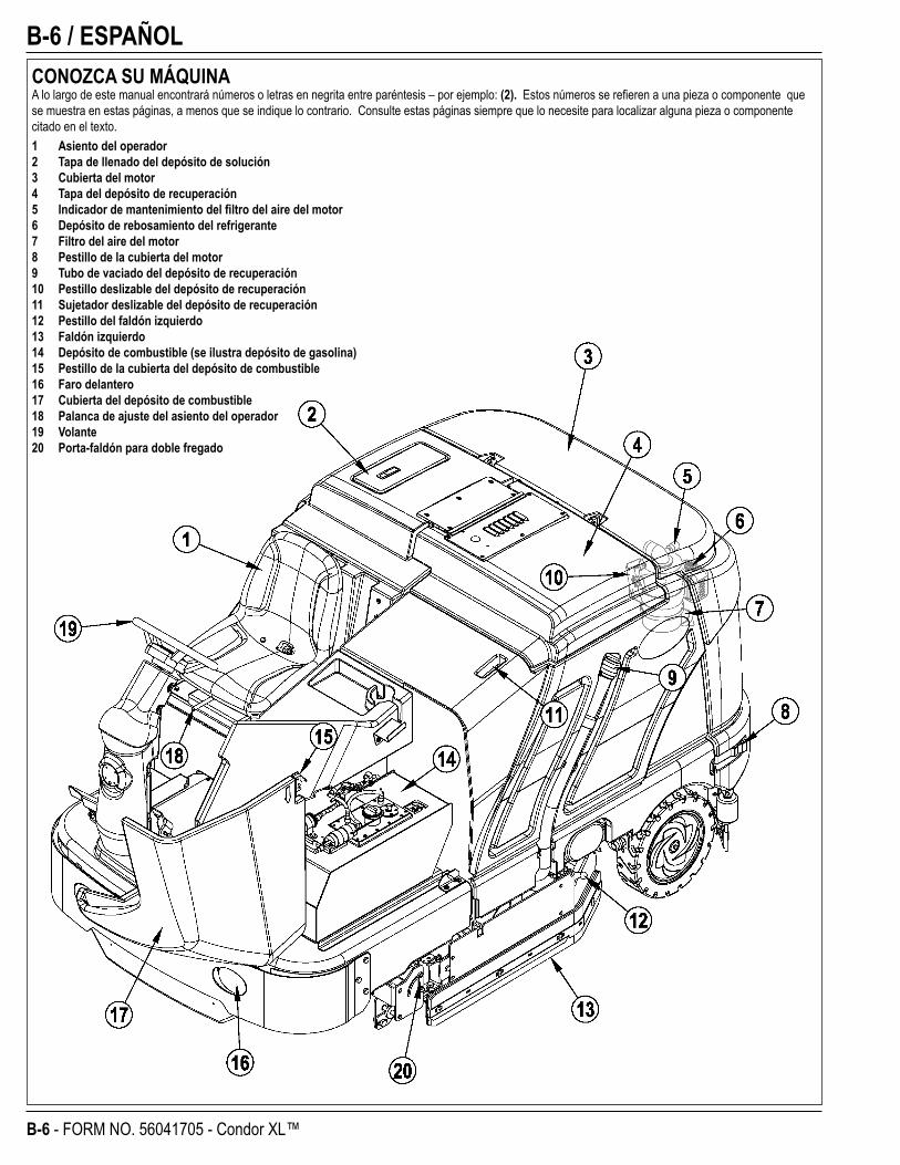
CONOZCA SU MÁQUINAA lo largo de este manual encontrará números o letras en negrita entre paréntesis – por ejemplo: (2). Estos números se refi eren a una pieza o componente que se muestra en estas páginas, a menos que se indique lo contrario. Consulte estas páginas siempre que lo necesite para localizar alguna pieza o componente citado en el texto.1 Asiento del operador2 Tapa de llenado del depósito de solución3 Cubierta del motor4 Tapa del depósito de recuperación5 Indicador de mantenimiento del fi ltro del aire del motor6 Depósito de rebosamiento del refrigerante7 Filtro del aire del motor8 Pestillo de la cubierta del motor9 Tubo de vaciado del depósito de recuperación10 Pestillo deslizable del depósito de recuperación11 Sujetador deslizable del depósito de recuperación12 Pestillo del faldón izquierdo13 Faldón izquierdo14 Depósito de combustible (se ilustra depósito de gasolina)15 Pestillo de la cubierta del depósito de combustible16 Faro delantero17 Cubierta del depósito de combustible18 Palanca de ajuste del asiento del operador19 Volante20 Porta-faldón para doble fregado
ESPAÑOL / B-7
FORM NO. 56041705 - Condor XL™ - B-7
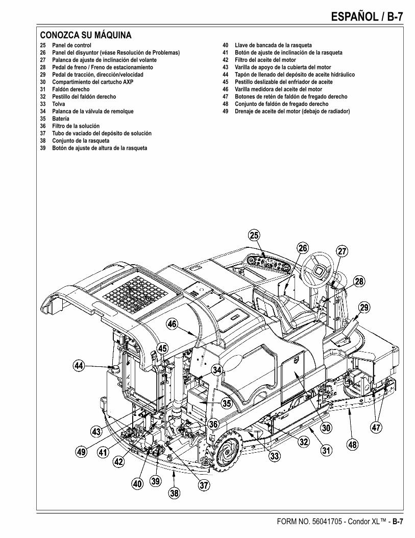
CONOZCA SU MÁQUINA25 Panel de control26 Panel del disyuntor (véase Resolución de Problemas)27 Palanca de ajuste de inclinación del volante28 Pedal de freno / Freno de estacionamiento29 Pedal de tracción, dirección/velocidad30 Compartimiento del cartucho AXP31 Faldón derecho32 Pestillo del faldón derecho33 Tolva34 Palanca de la válvula de remolque35 Batería36 Filtro de la solución37 Tubo de vaciado del depósito de solución38 Conjunto de la rasqueta39 Botón de ajuste de altura de la rasqueta
40 Llave de bancada de la rasqueta41 Botón de ajuste de inclinación de la rasqueta42 Filtro del aceite del motor43 Varilla de apoyo de la cubierta del motor44 Tapón de llenado del depósito de aceite hidráulico45 Pestillo deslizable del enfriador de aceite46 Varilla medidora del aceite del motor47 Botones de retén de faldón de fregado derecho48 Conjunto de faldón de fregado derecho49 Drenaje de aceite del motor (debajo de radiador)
B-8 / ESPAÑOL
B-8 - FORM NO. 56041705 - Condor XL™
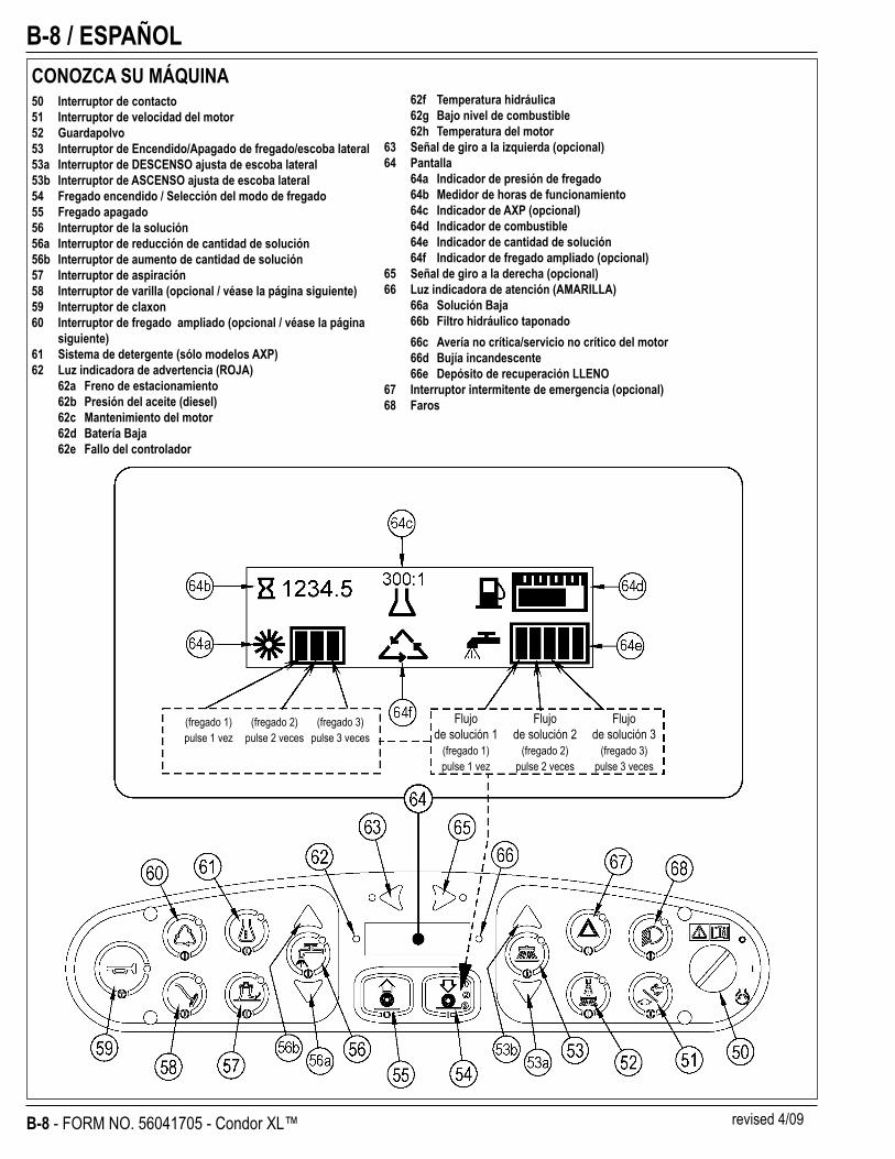
CONOZCA SU MÁQUINA50 Interruptor de contacto51 Interruptor de velocidad del motor52 Guardapolvo53 Interruptor de Encendido/Apagado de fregado/escoba lateral53a Interruptor de DESCENSO ajusta de escoba lateral53b Interruptor de ASCENSO ajusta de escoba lateral54 Fregado encendido / Selección del modo de fregado55 Fregado apagado56 Interruptor de la solución56a Interruptor de reducción de cantidad de solución56b Interruptor de aumento de cantidad de solución57 Interruptor de aspiración58 Interruptor de varilla (opcional / véase la página siguiente)59 Interruptor de claxon60 Interruptor de fregado ampliado (opcional / véase la página
siguiente)61 Sistema de detergente (sólo modelos AXP)62 Luz indicadora de advertencia (ROJA)
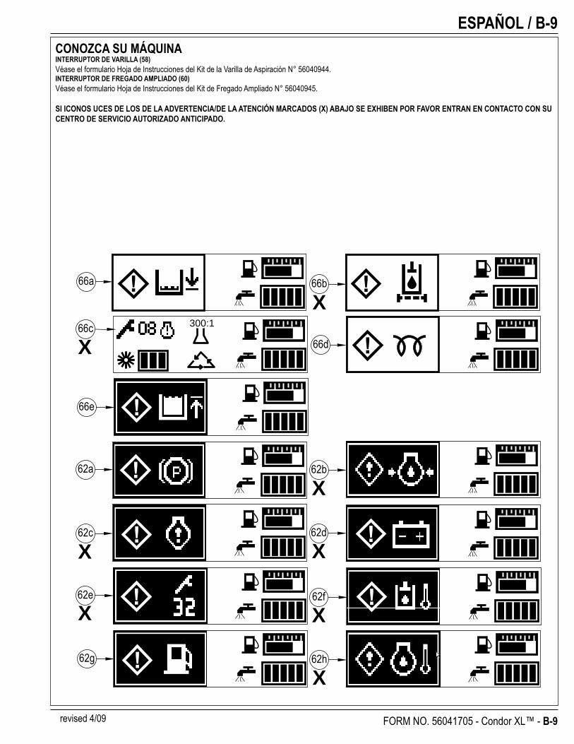
62a Freno de estacionamiento62b Presión del aceite (diesel)62c Mantenimiento del motor62d Batería Baja 62e Fallo del controlador
Flujo Flujo Flujo de solución 1 de solución 2 de solución 3 (fregado 1) (fregado 2) (fregado 3) pulse 1 vez pulse 2 veces pulse 3 veces
62f Temperatura hidráulica62g Bajo nivel de combustible62h Temperatura del motor
63 Señal de giro a la izquierda (opcional)64 Pantalla
64a Indicador de presión de fregado64b Medidor de horas de funcionamiento64c Indicador de AXP (opcional)64d Indicador de combustible64e Indicador de cantidad de solución64f Indicador de fregado ampliado (opcional)
65 Señal de giro a la derecha (opcional)66 Luz indicadora de atención (AMARILLA)
66a Solución Baja66b Filtro hidráulico taponado66c Avería no crítica/servicio no crítico del motor66d Bujía incandescente66e Depósito de recuperación LLENO
67 Interruptor intermitente de emergencia (opcional)68 Faros
(fregado 1) (fregado 2) (fregado 3) pulse 1 vez pulse 2 veces pulse 3 veces
revised 4/09
ESPAÑOL / B-9
FORM NO. 56041705 - Condor XL™ - B-9
CONOZCA SU MÁQUINAINTERRUPTOR DE VARILLA (58)Véase el formulario Hoja de Instrucciones del Kit de la Varilla de Aspiración N° 56040944.INTERRUPTOR DE FREGADO AMPLIADO (60)Véase el formulario Hoja de Instrucciones del Kit de Fregado Ampliado N° 56040945.
SI ICONOS UCES DE LOS DE LA ADVERTENCIA/DE LA ATENCIÓN MARCADOS (X) ABAJO SE EXHIBEN POR FAVOR ENTRAN EN CONTACTO CON SU CENTRO DE SERVICIO AUTORIZADO ANTICIPADO.
300:1
66a 66b
66c
62a
66e
62c 62d
62e 62f
62g
66d
62h
62b
X
X
X
X
X
X
X
X
revised 4/09

B-10 / ESPAÑOL
B-10 - FORM NO. 56041705 - Condor XL™
ELEVACIÓN DE LA MÁQUINA ¡PRECAUCIÓN!
No trabaje nunca debajo de la máquina sin colocar antes los soportes o bloques de seguridad para apoyar la máquina.• Cuando eleve la máquina, aplique los gatos en los lugares indicados - véase Puntos de Sujeción / Elevación (A) en la Figura 1.
TRANSPORTE DE LA MÁQUINA ¡PRECAUCIÓN!
Antes de transportar la máquina sobre un camión o remolque abierto, asegúrese de. . .• Cerrar bien todas las puertas de acceso.• La máquina está fi rmemente sujetada – véase Puntos de Sujeción / Elevación (A) en la Figura 1.• Echar el freno de estacionamiento de la máquina.
REMOLQUE O EMPUJE DE LA MÁQUINA EN CASO DE AVERÍA ¡PRECAUCIÓN!
La bomba de propulsión de transmisión de la máquina lleva una válvula de remolque ajustable que impide que se produzcan daños en el sistema hidráulico en caso de que deba remolcarse/empujarse la máquina a una distancia corta sin el uso del motor.La válvula de remolque es controlada por la palanca de la válvula de remolque (34) a la que se accede abriendo y sosteniendo la cubierta del motor (3). Tire hacia fuera la palanca de la válvula de remolque (34) soltándose de esta forma el bloqueo hidrostático entre el motor y la bomba.La bomba hidrostática puede sufrir daños si la máquina es remolcada con la válvula en posición normal de funcionamiento (palanca de la válvula de remolque (34) presionada). Nota: Si se deja la válvula de remolque en posición de rueda libre (palanca de la válvula de remolque (34) hacia afuera), la bomba hidrostática no puede impulsar la máquina ni hacia adelante ni hacia atrás. No se producirán daños, sólo tiene que volver a mover la válvula a la posición normal de funcionamiento colocando la palanca en posición activada. Remolque o empuje la máquina como máximo a paso normal (2-3 millas por hora) y sólo distancias cortas. Si necesita desplazar la máquina un tramo largo, la rueda motriz delantera debe elevarse para que no toque el suelo y colocarse sobre un gato rodante adecuado.
FIGURA 1
ESPAÑOL / B-11
FORM NO. 56041705 - Condor XL™ - B-11
COMPROBACIONES PREVIAS A LA UTILIZACIÓNAntes de cada utilización:* Examine la máquina para comprobar si existen daños o fugas de aceite o líquido de refrigeración.* Estruje la copa de goma del polvo del fi ltro del aire del motor (7) para retirar el polvo acumulado.* Compruebe el nivel del líquido de refrigeración del motor (6).* Compruebe el nivel de aceite del motor (46).* Compruebe el nivel de aceite hidráulico (44).* Compruebe el indicador del nivel de combustible (64d) en los modelos de gasolina y diesel.* Compruebe el indicador del nivel de combustible situado en el depósito de propano (14) en el modelo de propano.* Compruebe el indicador de servicio del fi ltro del aire (5).En el asiento del conductor:* El conductor debe conocer todos los controles y sus funciones.* Ajuste el asiento para alcanzar cómodamente todos los controles.* Introduzca la llave maestra y sitúe el interruptor de llave de encendido (50) en posición ON. Compruebe el funcionamiento correcto del claxon (59), el
contador horario (64b) y los faros delanteros (68). Sitúe el interruptor de llave de encendido (50) en OFF.* Compruebe el pedal de freno (28). El pedal debe estar fi rme y no debería ir hasta el fondo. El pestillo debería sostener el pedal estando presionado. (Comunique inmediatamente cualquier defecto al personal de mantenimiento).Planifi que su limpieza por adelantado:* Utilice la máquina en tramos largos, manteniendo al mínimo el número de detenciones y puestas en marcha. * Para cubrir toda la superfi cie, deje que los tramos de fregado su superpongan 2-3” (5,08-7,62 cm).* Evite tomar las curvas bruscamente, chocar contra postes y arañar los laterales de la máquina.
ACEITE HIDRÁULICOAbra y sostenga la cubierta del motor (3) para acceder al depósito de aceite hidráulico. Retire el tapón de llenado (44) del depósito y observe la parte inferior de la criba del llenador. Si el nivel de aceite está por debajo de la criba del llenador, agregue aceite de motor 10W30 hasta cubrir la criba del llenador (el nivel de aceite nunca debe estar más de 1/2” (12,7 mm) por encima de la parte inferior de la criba del llenador). Cambie el aceite si se produce una contaminación grave debida a un fallo mecánico.
ACEITE DEL MOTOR: GASOLINA Y PROPANO LÍQUIDOCompruebe el nivel del aceite del motor cuando la máquina esté estacionada sobre una superfi cie nivelada y el motor esté frío. Cambie el aceite del motor tras las primeras 35 horas de funcionamiento y, después, cada 150 horas. Utilice cualquier aceite de grado SF o SG que cumpla las especifi caciones del API y sea adecuado para las temperaturas de la estación. Consulte la sección Sistema del motor para conocer las capacidades del aceite y las especifi caciones adicionales del motor. Sustituya el fi ltro del aceite con cada cambio de aceite. TEMPERATURA PESO DEL ACEITE Más de 15°C SAE 10W-30 Menos de 15°C SAE 5W-30
ACEITE DEL MOTOR: DIESELCompruebe el nivel del aceite del motor cuando la máquina esté estacionada sobre una superfi cie nivelada y el motor esté frío. Cambie el aceite del motor tras las primeras 35 horas de funcionamiento y, después, cada 150 horas. Use aceite CF, CF-4 o CG-4 que cumpla las especifi caciones del API y sea adecuado para las temperaturas (*es importante consultar la nota sobre el tipo de aceite/combustible que aparece más adelante para obtener más recomendaciones sobre el aceite para diesel). Consulte la sección Sistema del motor para conocer las capacidades del aceite y las especifi caciones adicionales del motor. Sustituya el fi ltro del aceite con cada cambio de aceite. TEMPERATURA PESO DEL ACEITE Más de 25°C SAE 30 o 10W-30 De 0°C a 25°C SAE 20 o 10W-30 Menos de 0°C SAE 10W o 10W-30*Nota sobre el aceite lubricante para diesel: Con el control de emisiones ya en vigor, los aceites lubricantes CF-4 y CG-4 se han desarrollado para el uso de un combustible con bajo contenido de
azufre en motores para vehículos de carretera. Cuando el motor de un vehículo para fuera de la carretera funciona con un combustible con alto contenido en azufre, se recomienda emplear aceite lubricante CF, CD o CE con un número base total alto. Si se usa aceite lubricante CF-4 o CG-4 con un combustible con alto contenido en azufre, cambie el aceite lubricante a intervalos más cortos.
• Aceite lubricante recomendado cuando se utiliza un combustible con bajo contenido o con alto contenido en azufre.
CombustibleLubricanteClase de aceite
Bajo contenido de azufre
(0,5 % ≥)
Alto contenido de azufre Observaciones
CF O O Número base total ≥ 10
CF-4 O XCG-4 O X
O: Recomendable X: No recomendable
B-12 / ESPAÑOL
B-12 - FORM NO. 56041705 - Condor XL™
COMPROBACIONES PREVIAS A LA UTILIZACIÓNLÍQUIDO DE REFRIGERACIÓN DEL MOTOR
¡PRECAUCIÓN!No retire la tapa del radiador cuando el motor está caliente.Para comprobar el nivel de refrigerante del motor, abra y sostenga la cubierta del motor (3) y observe el nivel de refrigerante en el depósito de recuperación de refrigerante (6). Si el nivel está bajo, agregue un anticongelante del tipo automotor con la dilución correcta para el medio ambiente. Limpie el exterior del radiador y enfriador de aceite lavando con agua a baja presión o usando aire comprimido cada 30 horas. Nota de servicio: El enfriador de aceite se extrae para facilitar su limpieza.
FILTRO DEL AIRE DEL MOTORCompruebe el indicador de servicio del fi ltro del aire (5) cada vez antes de la utilización de la máquina. No realice operaciones de servicio en el fi ltro del aire si no aparece la bandera roja en el indicador de servicio.
¡PRECAUCIÓN!Cuando realice operaciones de servicio en los elementos del fi ltro de aire, extreme las precauciones para impedir que el polvo suelto penetre en el motor. El polvo podría dañarlo gravemente.El fi ltro del aire del motor contiene un elemento de fi ltro principal (externo) y un elemento de fi ltro de seguridad (interno). El elemento principal puede limpiarse dos veces antes ser sustituido. El elemento de seguridad debe cambiarse una vez por cada tres veces que se cambie el elemento de fi ltro principal. No intente nunca limpiar el elemento interno de seguridad.Para limpiar el elemento de fi ltro principal, retire las 2 pinzas del extremo del fi ltro del aire y retire el alojamiento del extremo. Saque el elemento principal y límpielo con aire comprimido (presión máxima: 100 libras por pulgada cuadrada) o lávelo con agua (presión máxima: 40 libras por pulgada cuadrada). NO vuelva a colocar el elemento en el cartucho hasta que esté completamente seco.
COMBUSTIBLE
¡ADVERTENCIA!• APAGUE SIEMPRE EL MOTOR ANTES DE LLENAR EL DEPÓSITO DE COMBUSTIBLE.• NO FUME CUANDO ESTÉ LLENANDO EL DEPÓSITO DE COMBUSTIBLE.• LLENE EL DEPÓSITO DE COMBUSTIBLE EN UN LUGAR BIEN VENTILADO.• NO LLENE EL DEPÓSITO DE COMBUSTIBLE CERCA DE CHISPAS O LLAMAS.• UTILICE SÓLO EL COMBUSTIBLE ESPECIFICADO EN LA PEGATINA DEL DEPÓSITO DE COMBUSTIBLE.En máquinas con motores diesel y gasolina, la pegatina cerca del cuello de llenado (14) indica el tipo de combustible que debe utilizarse en la máquina. Antes de retirar el tapón del depósito, limpie el polvo y la suciedad del tapón y de la zona superior del depósito, con el fi n de mantener el combustible lo más limpio posible.En las máquinas con motor de propano, la pegatina cerca del depósito contiene información específi ca sobre el tipo de depósito que se debe utilizar en la máquina.
MOTOR DIESELLlene el depósito con combustible diesel número 2 si la máquina se va a utilizar en una zona donde la temperatura es de 0° o superior. Utilice combustible diesel número 1 si la máquina se va a utilizar en una zona donde la temperatura está por debajo de los 0°.NOTA: Si la máquina diesel se queda sin combustible, el sistema de combustible debería alimentarse antes de volver a poner en marcha el motor. Para evitar esta situación, llene el depósito de combustible cuando el indicador del nivel de combustible muestre 1/4 en el depósito. La capacidad del depósito de combustible es de 42 litros.
MOTOR DE GASOLINALLENE EL DEPÓSITO DE GASOLINA NORMAL SIN PLOMO DE 87 OCTANOS. LA CAPACIDAD DEL DEPÓSITO DE COMBUSTIBLE ES DE 42 LITROS.Nota: Si desea datos más detallados sobre especifi caciones y servicio del motor, consulte el manual de utilización y mantenimiento del motor elaborado por el fabricante y entregado por separado.
MOTOR DE PROPANOInstale un depósito de 14,85 kg de propano líquido de retirada en la máquina, conecte la manguera de combustible y abra la válvula de cierre despacio en el depósito. Póngase guantes para conectar o desconectar la manguera de combustible. Cuando no esté utilizando la máquina, cierre la válvula de servicio del depósito de propano.
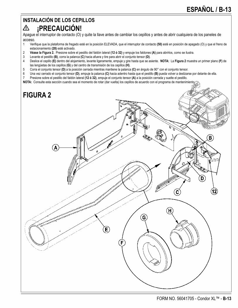
ESPAÑOL / B-13
FORM NO. 56041705 - Condor XL™ - B-13
INSTALACIÓN DE LOS CEPILLOS ¡PRECAUCIÓN!
Apague el interruptor de contacto (O) y quite la llave antes de cambiar los cepillos y antes de abrir cualquiera de los paneles de acceso.1 Verifi que que la plataforma de fregado esté en la posición ELEVADA, que el interruptor de contacto (50) esté en posición de apagado (O) y que el freno de
estacionamiento (28) esté activado.2 Véase la Figura 2. Presione sobre el pestillo del faldón lateral (12 ó 32) y empuje los faldones (A) para abrirlos, como se ilustra.3 Levante el pestillo (B), corra la palanca (C) hacia afuera y tire para abrir el conjunto tensor (D).4 Deslice el cepillo (E) dentro del alojamiento, levante ligeramente, empuje y gire hasta que se asiente. NOTA: La Figura 2 muestra un primer plano (F) de
las lengüetas de los cepillos (G) y del centro de transmisión de los cepillos (H).5 Corra el conjunto tensor (D) a la posición cerrada mientras mantiene la palanca (C) en ángulo de 90° con el conjunto tensor.6 Una vez cerrado el conjunto tensor (D), empuje la palanca (C) hacia adentro hasta que el pestillo (B) pueda volver a deslizarse por delante de ella.7 Presione sobre el pestillo del faldón lateral (12 ó 32), empuje el conjunto tensor (A) a la posición cerrada y suelte el pestillo.NOTA: Consulte esta sección cuando sea el momento de rotar (dar vuelta) los cepillos de acuerdo con el programa de mantenimiento.
FIGURA 2
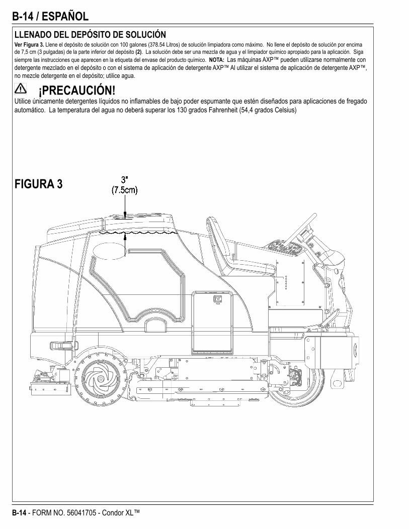
B-14 / ESPAÑOL
B-14 - FORM NO. 56041705 - Condor XL™
LLENADO DEL DEPÓSITO DE SOLUCIÓNVer Figura 3. Llene el depósito de solución con 100 galones (378.54 Litros) de solución limpiadora como máximo. No llene el depósito de solución por encima de 7,5 cm (3 pulgadas) de la parte inferior del depósito (2). La solución debe ser una mezcla de agua y el limpiador químico apropiado para la aplicación. Siga siempre las instrucciones que aparecen en la etiqueta del envase del producto químico. NOTA: Las máquinas AXP™ pueden utilizarse normalmente con detergente mezclado en el depósito o con el sistema de aplicación de detergente AXP™ Al utilizar el sistema de aplicación de detergente AXP™, no mezcle detergente en el depósito; utilice agua.
¡PRECAUCIÓN!Utilice únicamente detergentes líquidos no infl amables de bajo poder espumante que estén diseñados para aplicaciones de fregado automático. La temperatura del agua no deberá superar los 130 grados Fahrenheit (54,4 grados Celsius)
FIGURA 3
ESPAÑOL / B-15
FORM NO. 56041705 - Condor XL™ - B-15
FUNCIONAMIENTO DE LA MÁQUINALa Condor XL™ es una máquina automática de fregado de suelos sobre ruedas. Está diseñada para verter una solución de limpieza, fregar el suelo y secar al vacío todo de una sola pasada.Los controles de la Condor XL fueron diseñados pensando en una operación con un solo toque (one touch operation). Para el fregado de una sola pasada, el operador sólo tiene que pulsar un interruptor y se activarán todas las funciones de fregado de la máquina.NOTA: Los números que aparecen en negrita entre paréntesis indican elementos ilustrados en las páginas 6-9.NOTA: ASEGÚRESE DE QUE EL PEDAL ESTÉ EN LA POSICIÓN NEUTRAL. EL MOTOR NO ARRANCA SI EL PEDAL NO ESTÁ EN NEUTRAL.ENCENDIDO DEL MOTOR DIESEL1 Gire el interruptor de contacto (50) en el sentido de las agujas del reloj hasta la posición ENCENDIDO (ON). Las bujías incandescentes se activarán durante
10 segundos como lo señala la luz indicadora de atención (66) y el icono de bujías incandescentes (66d) de la pantalla. Si el motor ya está caliente, gire el interruptor de contacto hasta la posición de encendido para encender el motor. Si el motor está frío, antes de encenderlo espere que se apaguen la luz indicadora de atención y el icono de bujías incandescentes. El motor debería encenderse inmediatamente. Si el motor no arranca dentro de los 15 segundos, suelte el contacto, espere alrededor de 1 minuto y repita los pasos anteriores.
2 Deje el motor en punto muerto “IDLE” durante 5 minutos antes de hacer funcionar la máquina.3 Presione una vez el Interruptor de Velocidad del Motor (51) para cambiar a ACELERACIÓN MÁXIMA y dé unas vueltas con la máquina durante 2 ó 3
minutos a velocidad baja para calentar el sistema hidráulico.
ENCENDIDO DEL MOTOR DE GASOLINA1 Gire el interruptor de llave de encendido (50) en el sentido de las agujas del reloj hacia la posición START (arrancar) y suéltelo en cuanto arranque el motor.
Si el motor no arranca en 15 segundos, suelte la llave, espere 1 minuto y vuelva a intentarlo.2 Deje el motor en punto muerto “IDLE” durante 5 minutos antes de utilizar la máquina.3 Sitúe el interruptor de velocidad del motor (51) en posición de máxima aceleración y dé unas vueltas con la máquina durante 2 ó 3 minutos a velocidad baja
para calentar el sistema hidráulico.
ENCENDIDO DEL MOTOR DE PROPANO1 Abra la válvula de servicio del depósito de propano (14).2 Gire el interruptor de llave de encendido (50) en el sentido de las agujas del reloj hacia la posición START (arrancar) y suéltelo en cuanto arranque el motor.
Si el motor no arranca en 15 segundos, suelte la llave, espere 1 minuto y vuelva a intentarlo.3 Deje el motor en punto muerto “IDLE” durante 5 minutos antes de utilizar la máquina.4 Sitúe el interruptor de velocidad del motor (51) en posición de máxima aceleración y dé unas vueltas con la máquina durante 2 ó 3 minutos a velocidad baja
para calentar el sistema hidráulico.Utilice SIEMPRE la máquina con el interruptor de velocidad del motor en posición de máxima aceleración. Utilice el pedal de tracción (29) y no el interruptor de velocidad del motor (51) para controlar la velocidad de la máquina. La velocidad de la máquina aumentará cuanto más a fondo se pise el pedal. No pise el pedal de tracción (29) hasta que haya arrancado el motor.
Interruptor de Velocidad del Motor (51):Con el interruptor de velocidad del motor (51) que está en el panel de control, se pueden seleccionar 3 velocidades de motor.1 “Idle” (Punto Muerto) (1200 RPM – Gasolina / GLP) (1300 RPM – Diesel. Úsela para calentar y enfriar el motor. La luz del interruptor de velocidad del
motor estará apagada.2 “Run” (Encendido) (2200 RPM). Úsela para transporte y la mayoría de operaciones de fregado. La luz del interruptor de velocidad del motor estará
encendida.3 “Turbo” (2400 RPM). Úsela sólo para situaciones de trabajos pesados como operaciones de fregado en pendientes. La luz del interruptor de velocidad del
motor estará encendida.4 Para seleccionar entre velocidad ralentí y de marcha, presione y suelte el interruptor de velocidad de motor. 5 Para seleccionar velocidad Turbo, primero ponga la velocidad en marcha. Luego presione y mantenga presionado el interruptor de velocidad del motor por
2 segundos. Para volver a la velocidad en marcha, vuelva a presionar el interruptor.6 La Condor XL tiene un mecanismo automático que reduce la velocidad del motor a punto muerto cada vez que el pedal (29) permanece en la posición
neutral durante 20 segundos o más. La velocidad de motor seleccionada se repone automáticamente al sacar el pedal de la posición neutral. Si el interruptor de velocidad del motor (51) está presionado estando en anulación de punto muerto, el mecanismo automático de pase a punto muerto quedará temporalmente desactivado hasta la vez siguiente en que el pedal salga de la posición neutral. Esto puede ser de utilidad durante una instancia de resolución de problemas o si se desea dejar la máquina funcionando a máxima velocidad para calentarla.
B-16 / ESPAÑOL
B-16 - FORM NO. 56041705 - Condor XL™
REPARACIÓN Y USO DEL SISTEMA DE DETERGENTE (SOLO MODELOS AXP)Llene el cartucho de detergente con 8,32 litros (2.2 galones) de detergente como máximo. NOTA DE SERVICIO: retire el cartucho de la caja de detergente antes de llenarlo para no derramar detergente sobre la máquina.Se recomienda utilizar un cartucho individual para cada detergente que planee usar. Los cartuchos de detergente tienen una pegatina blanca, de modo que puede escribir el nombre del detergente en cada cartucho para no mezclarlos. Al instalar un nuevo cartucho, retire la tapa (A) y coloque el cartucho en la caja de detergente. Instale la tapa sellada (B) como se muestra.Elimine del sistema el detergente utilizado anteriormente antes de cambiar a un detergente diferente. NOTA DE SERVICIO: desplace la máquina sobre un punto de drenaje en el suelo antes de eliminar el detergente, porque saldrá una pequeña cantidad durante el proceso.Cómo purgar cuando se cambian químicos (SISTEMA DE FREGADO DEBE ESTAR APAGADO):1 Desconecte y retire el cartucho de detergente.2 Gire el interruptor de contacto (50) hasta la posición ENCENDIDO (ON). Espere unos pocos segundos hasta que termine la secuencia de encendido.3 Presione y mantenga presionado el interruptor de detergente (61) durante aproximadamente 2 segundos. Suelte el interruptor cuando aparezca en la pantalla el icono de purga
de químicos (E) y comience a destellar el indicador del interruptor de detergente (61). NOTA: una vez activado, el proceso de purga dura como mínimo 10 segundos. Observe los indicadores del sistema de detergente en la ilustración de la página siguiente. Por lo general, un solo ciclo de purga es sufi ciente para purgar el sistema.
Purgar semanalmente (SISTEMA DE FREGADO DEBE ESTAR APAGADO):1 Desconecte y retire el cartucho de detergente. Instale y conecte un cartucho lleno de agua caliente limpia.2 Gire el interruptor de contacto (50) hasta la posición ENCENDIDO (ON). Espere unos pocos segundos hasta que termine la secuencia de encendido.3 Presione y mantenga presionado el interruptor de detergente (61) durante aproximadamente 2 segundos. Suelte el interruptor cuando aparezca en la pantalla el icono de purga
de químicos (E) y comience a destellar el indicador del interruptor de detergente (61). NOTA: una vez activado, el proceso de purga dura como mínimo 10 segundos. Observe los indicadores del sistema de detergente en la ilustración de la página siguiente. Por lo general, un solo ciclo de purga es sufi ciente para purgar el sistema.
La caja de detergente (C) tiene ranuras de visualización del nivel de detergente (D) para saber cuánto detergente queda en el o los cartucho(s). Cuando el nivel de detergente se acerque a la parte inferior de esta ranura, es hora de recargar o sustituir el cartucho.
Proporción de detergente (SISTEMA DE FREGADO DEBE ESTAR ENCENDIDO):La mezcla de detergente puede ajustarse presionando y manteniendo presionado el interruptor de detergente (61) durante 2 segundos. Suelte el interruptor una vez que la luz del interruptor de detergente comience a destellar. Estando la luz destellando, si presiona y suelta el interruptor de detergente se seleccionará la siguiente mezcla de detergente. Una vez seleccionada la mezcla deseada, el sistema de detergente retornará a la operación normal al cabo de 3 segundos.
La mezcla de detergente (F) se verá en pantalla durante 10 segundos aproximadamente cada vez que cambie el modo de fregado o cada vez que se presione el interruptor de detergente.
Una vez programado, el fl ujo del detergente aumenta o disminuye automáticamente con el fl ujo de la solución pero la proporción de detergente no varía. Si un operador prefi ere la fl exibilidad de programar diferentes proporciones de mezcla de detergente para diferentes fl ujos de solución, esta programación específi ca podría estar en el manual de servicio. Durante el fregado, el sistema de detergente puede apagarse en cualquier momento pulsando el interruptor de detergente (61) para que la máquina siga fregando solo con agua. No se administra detergente hasta que se activa el sistema de fregado y se presiona el pedal de tracción (29).NOTA DE SERVICIO: Siga las instrucciones “Purgar semanalmente” indicadas más arriba toda vez que la máquina vaya a quedar almacenada durante un periodo de tiempo prolongado o cuando prevea no usar el sistema de de detergente (AXP).
revised 4/09
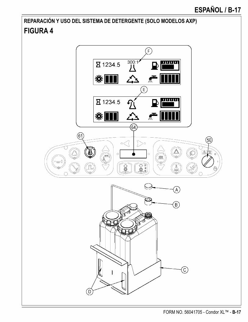
ESPAÑOL / B-17
FORM NO. 56041705 - Condor XL™ - B-17
REPARACIÓN Y USO DEL SISTEMA DE DETERGENTE (SOLO MODELOS AXP)
FIGURA 4
B-18 / ESPAÑOL
B-18 - FORM NO. 56041705 - Condor XL™
FREGADO ¡ADVERTENCIA!
Asegúrese de que comprende los controles del operador y sus funciones.Al circular sobre rampas o pendientes, evite las paradas bruscas si lleva carga. Evite las curvas muy cerradas. Circule lentamente al bajar pendientes.Para fregar...Siga las instrucciones de la sección “Preparación de la máquina para su uso” de este manual. Encienda el motor siguiendo las instrucciones de la sección “Encendido del motor ….” que corresponda.1 Ver la Figura 5. Sentado en la máquina y utilizando los controles de ajuste (18 y 27), coloque el asiento y el volante en una posición cómoda.2 Suelte el freno de estacionamiento (28). Para llevar la máquina a la zona de trabajo, aplique con el pie una presión uniforme en la parte delantera del pedal de tracción (29)
para ir hacia delante, o en la parte trasera del pedal para ir hacia atrás. Cambie la presión que ejerce en el pedal para obtener la velocidad deseada.3 Pulse y mantenga pulsado el interruptor de la solución (56) durante 5 segundos para mojar el suelo. NOTA: esto ayuda a evitar la escarifi cación de la superfi cie del suelo
cuando se empieza a fregar con cepillos secos. Esto debe realizarse antes de pulsar el interruptor de encendido del fregado (54).4 Presione el interruptor de encendido del fregado (54) una vez para seleccionar el modo de fregado ligero (1), dos veces para seleccionar el modo fregado medio (2) o tres veces
para seleccionar el modo fregado intenso. Los fl ujos de solución y detergente (modelos AXP) tienen 3 programaciones que coinciden con los 3 modos de fregado (ver panel de control (64)). Al presionar este interruptor, también se afecta la presión del cepillo derecho.NOTA: El fl ujo de la solución puede anularse simplemente presionando los interruptores de aumento o reducción del fl ujo de la solución (56a / 56b). Los ajustes posteriores de la presión de fregado restablecerán el fl ujo de la solución para que se corresponda con la presión de fregado.NOTA: Los sistemas de fregado, solución, aspiración, detergente (modelos AXP) y cepillo / escoba(s) lateral(es) se habilitan automáticamente cuando se pulsa el interruptor de encendido del fregado (54). Cualquier sistema individual puede apagarse o volver a encenderse con sólo presionar su interruptor en cualquier momento durante el fregado. Si ha instalado el kit fregado ampliado, no se activará automáticamente. Para activar este sistema, debe pulsar el interruptor de fregado ampliado (G0). El sistema de fregado ampliado no se activará hasta que el agua del depósito de recuperación llegue a un determinado nivel y la solución limpia se haya agotado.
5 Cuando se selecciona el interruptor de encendido del fregado (54), los cepillos, la rasqueta y cepillo / escoba(s) laterales se bajan automáticamente hasta el suelo. Los sistemas de fregado, solución, aspiración, detergente (modelos AXP) y cepillo / escoba(s) laterales se encienden cuando se activa el pedal de tracción (29).NOTA: Cuando la máquina está funcionando marcha atrás, la rasqueta automáticamente se eleva y la solución deja de salir.
6 Empiece a fregar conduciendo la máquina marcha adelante en línea recta a una velocidad de paso normal, y haga que los tramos de pasada se solapen o superpongan 2-3” (5,08-7,62 cm). Ajuste la velocidad de la máquina y el fl ujo de la solución cuando sea necesario según el estado del suelo.
Puede ajustar la altura de la escoba lateral presionando sus interruptores DOWN y UP (hacia abajo y hacia arriba) (53a / 53b). La(s) escoba(s) lateral(es) retornarán a la última posición utilizada cada vez que se encienda el sistema de barrido. Las escobas laterales tienen una función de vaporización (Guardapolvo) (52) para usar en presencia de superfi cies con polvo. NOTA: El “Guardapolvo” (52) se activa automáticamente con las Escobas Laterales (53) pero puede apagarse presionando (52). NOTA: Si estuviera equipado con Fregado Ampliado, el “Guardapolvo” se apagará cuando la máquina se quede sin solución limpia.
¡PRECAUCIÓN!Para no dañar el suelo, mantenga la máquina en movimiento mientras giran los cepillos (los cepillos se apagarán al cabo de una demora de 2 segundos cuando el pedal de tracción está colocado en la posición neutral).Cuando tenga que atravesar policías acostados, eleve la plataforma de fregado y el cepillo de fregado lateral, de venir instalado. En estos casos, no intente hacer funcionar la plataforma de fregado o el cepillo lateral estando en la posición baja. La presión hidráulica empuja los cepillos hacia abajo y trabajar en modo de fregado sobre un policía acostado podría dañar su máquina.7 Cuando friegue, compruebe de vez en cuando que detrás de la máquina se está recogiendo el agua residual. Si queda agua en la trayectoria de la máquina, puede que esté
aplicando demasiada solución, que el depósito de recuperación esté lleno o que la rasqueta necesite un ajuste.8 Para los suelos muy sucios, puede que una operación de fregado de una sola pasada no sea sufi ciente y que se necesite un “doble fregado”. Esta operación es idéntica a la de
fregado de una sola pasada, salvo que en la primera pasada la rasqueta está en la posición levantada (pulse el interruptor de aspiración (57) para levantar la rasqueta). Esto permite que la solución de limpieza permanezca en el suelo y actúe más tiempo. Los faldones laterales (13 y 31) también pueden elevarse para un doble fregado, en caso de ser necesario, con los porta-faldones (20). La última pasada se hace sobre la misma superfi cie, con la rasqueta y los faldones bajados para recoger la solución acumulada.
9 Cuando el depósito de recuperación está lleno, hay un dispositivo que apaga TODOS los sistemas excepto el sistema de tracción. Al activarse este dispositivo, hay que vaciar el depósito de recuperación. La máquina no recogerá agua ni fregará con el dispositivo activado.
NOTA: Cuando se activa el dispositivo, la luz indicadora de atención (66) se enciende en color AMARILLA y se activa el icono de depósito de recuperación lleno (66e) Si el control indica depósito lleno repetidamente, verifi que que el dispositivo se mueva libremente.
10 Cuando quiera detener la operación de fregado, presione una vez el interruptor de apagado del fregado (55). Automáticamente se detendrán los cepillos de fregado, el(los) cepillos / escobas laterales y la salida de solución y detergente. La plataforma de fregado y el (los) cepillos / escobas laterales se elevarán. La rasqueta se levantará y la aspiración se detendrá tras un breve intervalo de tiempo (esto es así para que se pueda recoger el agua que haya podido quedar sin tener que volver a encender la aspiración).
11 Conduzca la máquina a un lugar establecido para la eliminación de aguas residuales y vacíe el depósito de recuperación. Para vaciarlo, tire del tubo de vaciado (9) para sacarlo de su zona de almacenamiento y, a continuación, retire el tapón (sostenga el extremo del tubo por encima del nivel de agua para evitar el fl ujo súbito e incontrolado de agua residual). Para regular el fl ujo, puede apretar el tubo de vaciado del depósito de recuperación (9). Rellene el depósito de solución y siga fregando.
NOTA: asegúrese de que la tapa del depósito de recuperación (4) y el tapón del tubo de vaciado del depósito de recuperación (9) estén bien asentados, o la máquina no recogerá el agua correctamente.
NOTA DE SERVICIO: Consulte el anual de servicio para ver opciones de programación.
revised 4/09
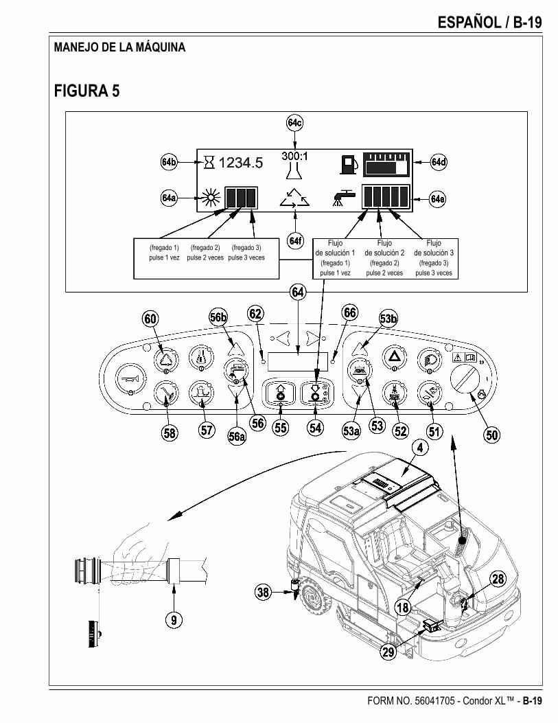
ESPAÑOL / B-19
FORM NO. 56041705 - Condor XL™ - B-19
MANEJO DE LA MÁQUINA
FIGURA 5
Flujo Flujo Flujo de solución 1 de solución 2 de solución 3 (fregado 1) (fregado 2) (fregado 3) pulse 1 vez pulse 2 veces pulse 3 veces
(fregado 1) (fregado 2) (fregado 3) pulse 1 vez pulse 2 veces pulse 3 veces
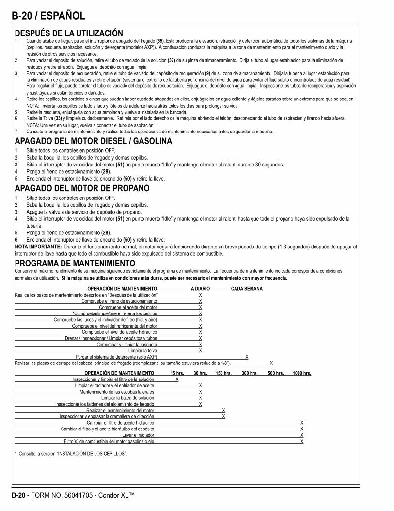
B-20 / ESPAÑOL
B-20 - FORM NO. 56041705 - Condor XL™
DESPUÉS DE LA UTILIZACIÓN1 Cuando acabe de fregar, pulse el interruptor de apagado del fregado (55). Esto producirá la elevación, retracción y detención automática de todos los sistemas de la máquina
(cepillos, rasqueta, aspiración, solución y detergente (modelos AXP)). A continuación conduzca la máquina a la zona de mantenimiento para el mantenimiento diario y la revisión de otros servicios necesarios.
2 Para vaciar el depósito de solución, retire el tubo de vaciado de la solución (37) de su pinza de almacenamiento. Dirija el tubo al lugar establecido para la eliminación de residuos y retire el tapón. Enjuague el depósito con agua limpia.
3 Para vaciar el depósito de recuperación, retire el tubo de vaciado del depósito de recuperación (9) de su zona de almacenamiento. Dirija la tubería al lugar establecido para la eliminación de aguas residuales y retire el tapón (sostenga el extremo de la tubería por encima del nivel de agua para evitar el fl ujo súbito e incontrolado de agua residual). Para regular el fl ujo, puede apretar el tubo de vaciado del depósito de recuperación. Enjuague el depósito con agua limpia. Inspeccione los tubos de recuperación y aspiración y sustitúyalas si están torcidos o dañados.
4 Retire los cepillos, los cordeles o cintas que puedan haber quedado atrapados en ellos, enjuáguelos en agua caliente y déjelos parados sobre un extremo para que se sequen. NOTA: Invierta los cepillos de lado a lado y rótelos de adelante hacia atrás todos los días para prolongar su vida.
5 Retire la rasqueta, enjuáguela con agua templada y vuelva a instalarla en la bancada.6 Retire la Tolva (33) y límpiela cuidadosamente. Retírela por el lado derecho de la máquina abriendo el faldón, desconectando el tubo de aspiración y tirando hacia afuera.
NOTA: Una vez en su lugar, vuelva a conectar el tubo de aspiración.7 Consulte el programa de mantenimiento y realice todas las operaciones de mantenimiento necesarias antes de guardar la máquina.
APAGADO DEL MOTOR DIESEL / GASOLINA1 Sitúe todos los controles en posición OFF.2 Suba la boquilla, los cepillos de fregado y demás cepillos.3 Sitúe el interruptor de velocidad del motor (51) en punto muerto “Idle” y mantenga el motor al ralentí durante 30 segundos.4 Ponga el freno de estacionamiento (28).5 Encienda el interruptor de llave de encendido (50) y retire la llave.
APAGADO DEL MOTOR DE PROPANO1 Sitúe todos los controles en posición OFF.2 Suba la boquilla, los cepillos de fregado y demás cepillos.3 Apague la válvula de servicio del depósito de propano.4 Sitúe el interruptor de velocidad del motor (51) en punto muerto “Idle” y mantenga el motor al ralentí hasta que todo el propano haya sido expulsado de la
tubería.5 Ponga el freno de estacionamiento (28).6 Encienda el interruptor de llave de encendido (50) y retire la llave.NOTA IMPORTANTE: Durante el funcionamiento normal, el motor seguirá funcionando durante un breve periodo de tiempo (1-3 segundos) después de apagar el interruptor de llave hasta que todo el combustible haya sido expulsado del sistema de combustible.
PROGRAMA DE MANTENIMIENTOConserve el máximo rendimiento de su máquina siguiendo estrictamente el programa de mantenimiento. La frecuencia de mantenimiento indicada corresponde a condiciones normales de utilización. Si la máquina se utiliza en condiciones más duras, puede ser necesario el mantenimiento con mayor frecuencia.
OPERACIÓN DE MANTENIMIENTO A DIARIO CADA SEMANA Realice los pasos de mantenimiento descritos en “Después de la utilización” X Compruebe el freno de estacionamiento X Compruebe el aceite del motor X *Compruebe/limpie/gire e invierta los cepillos X Compruebe las luces y el indicador de fi ltro (hid. y aire) X Compruebe el nivel del refrigerante del motor X Compruebe el nivel del aceite hidráulico X Drenar / Inspeccionar / Limpiar depósitos y tubos X Comprobar y limpiar la rasqueta X Limpiar la tolva X Purgar el sistema de detergente (sólo AXP) X Revisar las placas de derrape del cabezal principal de fregado (reemplazar si su tamaño estuviera reducido a 1/8”). X
OPERACIÓN DE MANTENIMIENTO 15 hrs. 30 hrs. 150 hrs. 300 hrs. 500 hrs. 1000 hrs. Inspeccionar y limpiar el fi ltro de la solución X Limpiar el radiador y el enfriador de aceite X Mantenimiento de las escobas laterales X Limpiar la batea de solución X Inspeccionar los faldones del alojamiento de fregado X Realizar el mantenimiento del motor X Inspeccionar y engrasar la cremallera de dirección X Cambiar el fi ltro de aceite hidráulico X Cambiar el fi ltro y el aceite hidráulico del depósito X Lavar el radiador X Filtro(s) de combustible del motor gasolina o glp X
* Consulte la sección “INSTALACIÓN DE LOS CEPILLOS”.
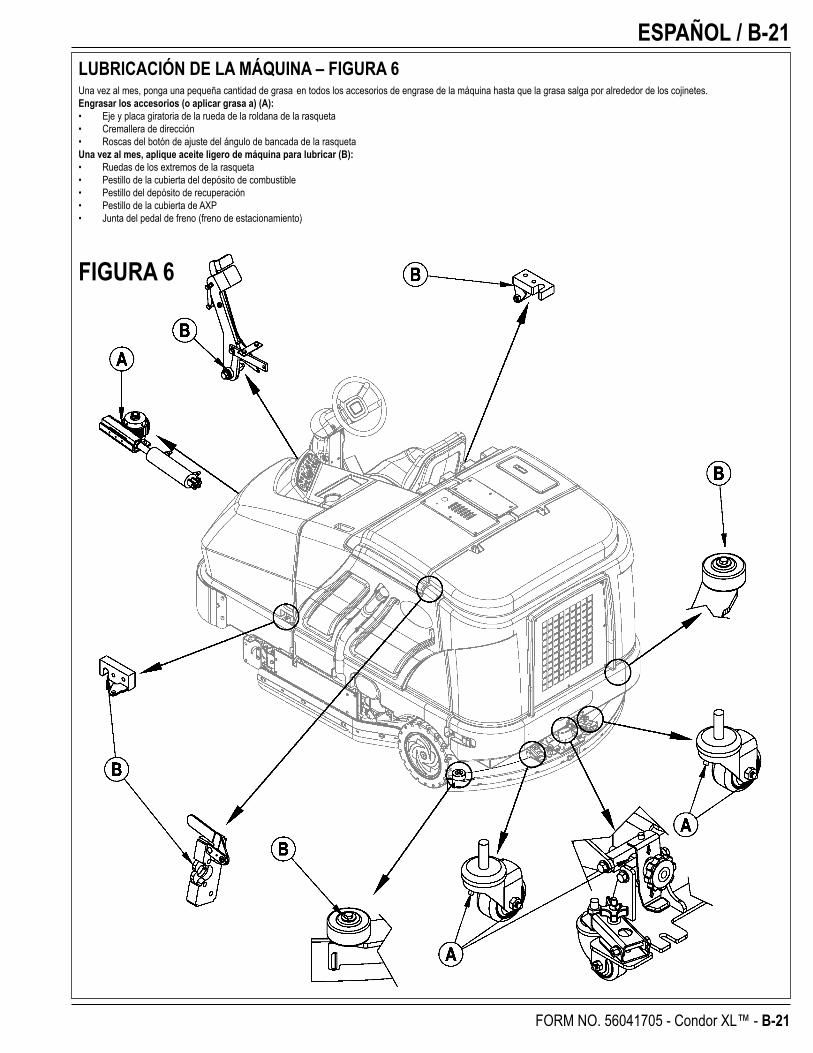
ESPAÑOL / B-21
FORM NO. 56041705 - Condor XL™ - B-21
FIGURA 6
LUBRICACIÓN DE LA MÁQUINA – FIGURA 6Una vez al mes, ponga una pequeña cantidad de grasa en todos los accesorios de engrase de la máquina hasta que la grasa salga por alrededor de los cojinetes.Engrasar los accesorios (o aplicar grasa a) (A):• Eje y placa giratoria de la rueda de la roldana de la rasqueta• Cremallera de dirección• Roscas del botón de ajuste del ángulo de bancada de la rasquetaUna vez al mes, aplique aceite ligero de máquina para lubricar (B):• Ruedas de los extremos de la rasqueta• Pestillo de la cubierta del depósito de combustible• Pestillo del depósito de recuperación• Pestillo de la cubierta de AXP• Junta del pedal de freno (freno de estacionamiento)
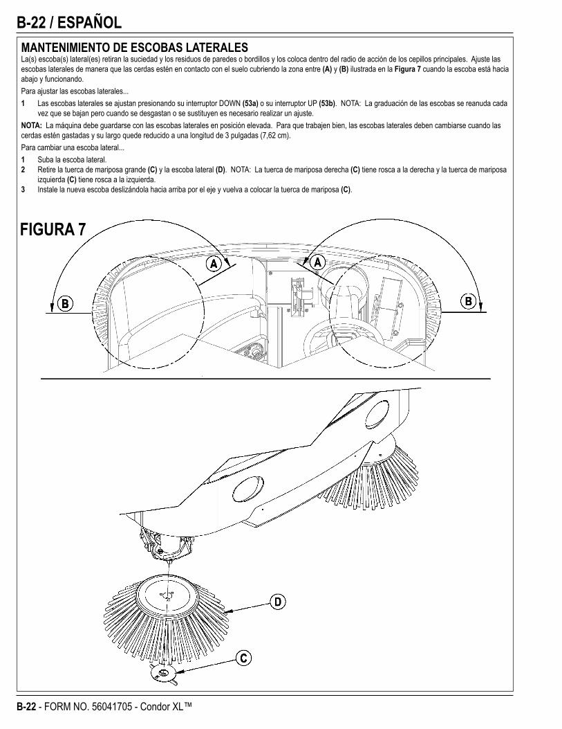
B-22 / ESPAÑOL
B-22 - FORM NO. 56041705 - Condor XL™
MANTENIMIENTO DE ESCOBAS LATERALESLa(s) escoba(s) lateral(es) retiran la suciedad y los residuos de paredes o bordillos y los coloca dentro del radio de acción de los cepillos principales. Ajuste las escobas laterales de manera que las cerdas estén en contacto con el suelo cubriendo la zona entre (A) y (B) ilustrada en la Figura 7 cuando la escoba está hacia abajo y funcionando.Para ajustar las escobas laterales...1 Las escobas laterales se ajustan presionando su interruptor DOWN (53a) o su interruptor UP (53b). NOTA: La graduación de las escobas se reanuda cada
vez que se bajan pero cuando se desgastan o se sustituyen es necesario realizar un ajuste.NOTA: La máquina debe guardarse con las escobas laterales en posición elevada. Para que trabajen bien, las escobas laterales deben cambiarse cuando las cerdas estén gastadas y su largo quede reducido a una longitud de 3 pulgadas (7,62 cm).Para cambiar una escoba lateral...1 Suba la escoba lateral.2 Retire la tuerca de mariposa grande (C) y la escoba lateral (D). NOTA: La tuerca de mariposa derecha (C) tiene rosca a la derecha y la tuerca de mariposa
izquierda (C) tiene rosca a la izquierda.3 Instale la nueva escoba deslizándola hacia arriba por el eje y vuelva a colocar la tuerca de mariposa (C).
FIGURA 7
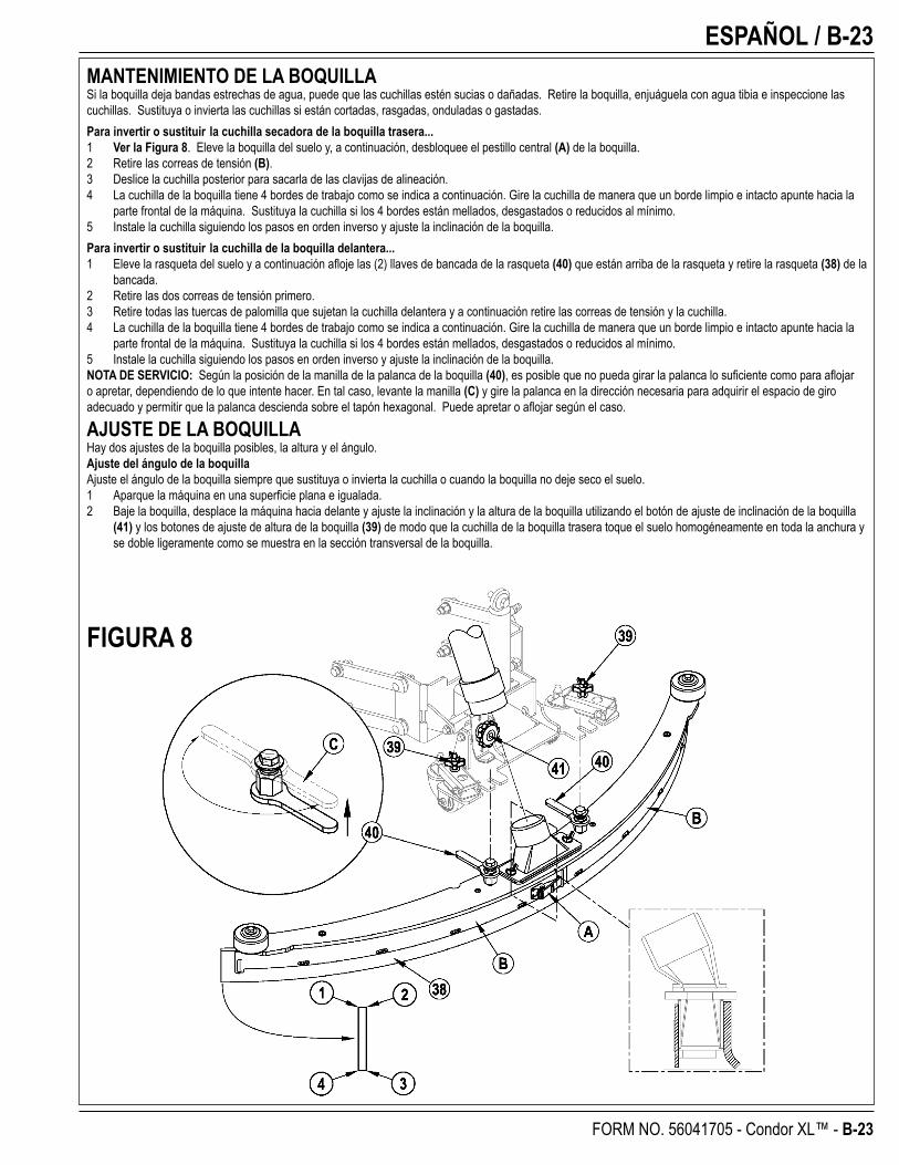
ESPAÑOL / B-23
FORM NO. 56041705 - Condor XL™ - B-23
FIGURA 8
MANTENIMIENTO DE LA BOQUILLASi la boquilla deja bandas estrechas de agua, puede que las cuchillas estén sucias o dañadas. Retire la boquilla, enjuáguela con agua tibia e inspeccione las cuchillas. Sustituya o invierta las cuchillas si están cortadas, rasgadas, onduladas o gastadas.Para invertir o sustituir la cuchilla secadora de la boquilla trasera...1 Ver la Figura 8. Eleve la boquilla del suelo y, a continuación, desbloquee el pestillo central (A) de la boquilla.2 Retire las correas de tensión (B).3 Deslice la cuchilla posterior para sacarla de las clavijas de alineación.4 La cuchilla de la boquilla tiene 4 bordes de trabajo como se indica a continuación. Gire la cuchilla de manera que un borde limpio e intacto apunte hacia la
parte frontal de la máquina. Sustituya la cuchilla si los 4 bordes están mellados, desgastados o reducidos al mínimo.5 Instale la cuchilla siguiendo los pasos en orden inverso y ajuste la inclinación de la boquilla.Para invertir o sustituir la cuchilla de la boquilla delantera...1 Eleve la rasqueta del suelo y a continuación afl oje las (2) llaves de bancada de la rasqueta (40) que están arriba de la rasqueta y retire la rasqueta (38) de la
bancada.2 Retire las dos correas de tensión primero.3 Retire todas las tuercas de palomilla que sujetan la cuchilla delantera y a continuación retire las correas de tensión y la cuchilla. 4 La cuchilla de la boquilla tiene 4 bordes de trabajo como se indica a continuación. Gire la cuchilla de manera que un borde limpio e intacto apunte hacia la
parte frontal de la máquina. Sustituya la cuchilla si los 4 bordes están mellados, desgastados o reducidos al mínimo.5 Instale la cuchilla siguiendo los pasos en orden inverso y ajuste la inclinación de la boquilla.NOTA DE SERVICIO: Según la posición de la manilla de la palanca de la boquilla (40), es posible que no pueda girar la palanca lo sufi ciente como para afl ojar o apretar, dependiendo de lo que intente hacer. En tal caso, levante la manilla (C) y gire la palanca en la dirección necesaria para adquirir el espacio de giro adecuado y permitir que la palanca descienda sobre el tapón hexagonal. Puede apretar o afl ojar según el caso.
AJUSTE DE LA BOQUILLAHay dos ajustes de la boquilla posibles, la altura y el ángulo.Ajuste del ángulo de la boquillaAjuste el ángulo de la boquilla siempre que sustituya o invierta la cuchilla o cuando la boquilla no deje seco el suelo.1 Aparque la máquina en una superfi cie plana e igualada.2 Baje la boquilla, desplace la máquina hacia delante y ajuste la inclinación y la altura de la boquilla utilizando el botón de ajuste de inclinación de la boquilla
(41) y los botones de ajuste de altura de la boquilla (39) de modo que la cuchilla de la boquilla trasera toque el suelo homogéneamente en toda la anchura y se doble ligeramente como se muestra en la sección transversal de la boquilla.
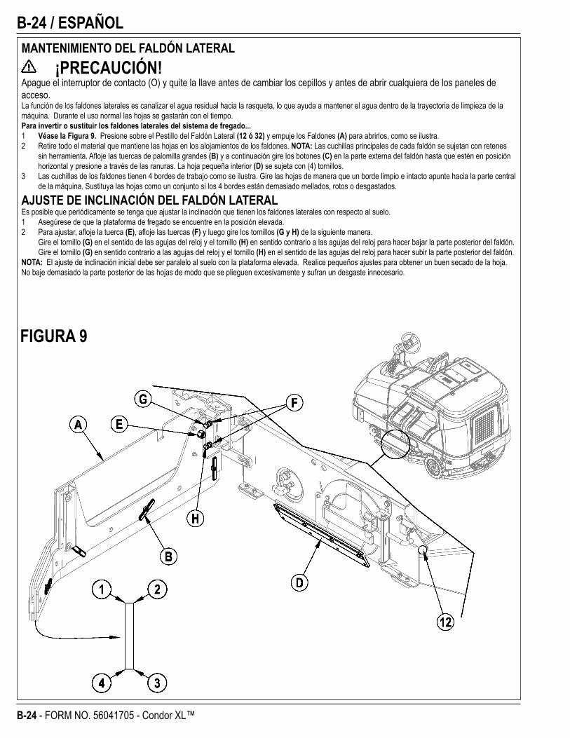
B-24 / ESPAÑOL
B-24 - FORM NO. 56041705 - Condor XL™
MANTENIMIENTO DEL FALDÓN LATERAL ¡PRECAUCIÓN!
Apague el interruptor de contacto (O) y quite la llave antes de cambiar los cepillos y antes de abrir cualquiera de los paneles de acceso.La función de los faldones laterales es canalizar el agua residual hacia la rasqueta, lo que ayuda a mantener el agua dentro de la trayectoria de limpieza de la máquina. Durante el uso normal las hojas se gastarán con el tiempo.Para invertir o sustituir los faldones laterales del sistema de fregado...1 Véase la Figura 9. Presione sobre el Pestillo del Faldón Lateral (12 ó 32) y empuje los Faldones (A) para abrirlos, como se ilustra.2 Retire todo el material que mantiene las hojas en los alojamientos de los faldones. NOTA: Las cuchillas principales de cada faldón se sujetan con retenes
sin herramienta. Afl oje las tuercas de palomilla grandes (B) y a continuación gire los botones (C) en la parte externa del faldón hasta que estén en posición horizontal y presione a través de las ranuras. La hoja pequeña interior (D) se sujeta con (4) tornillos.
3 Las cuchillas de los faldones tienen 4 bordes de trabajo como se ilustra. Gire las hojas de manera que un borde limpio e intacto apunte hacia la parte central de la máquina. Sustituya las hojas como un conjunto si los 4 bordes están demasiado mellados, rotos o desgastados.
AJUSTE DE INCLINACIÓN DEL FALDÓN LATERALEs posible que periódicamente se tenga que ajustar la inclinación que tienen los faldones laterales con respecto al suelo.1 Asegúrese de que la plataforma de fregado se encuentre en la posición elevada.2 Para ajustar, afl oje la tuerca (E), afl oje las tuercas (F) y luego gire los tornillos (G y H) de la siguiente manera. Gire el tornillo (G) en el sentido de las agujas del reloj y el tornillo (H) en sentido contrario a las agujas del reloj para hacer bajar la parte posterior del faldón. Gire el tornillo (G) en sentido contrario a las agujas del reloj y el tornillo (H) en el sentido de las agujas del reloj para hacer subir la parte posterior del faldón.NOTA: El ajuste de inclinación inicial debe ser paralelo al suelo con la plataforma elevada. Realice pequeños ajustes para obtener un buen secado de la hoja. No baje demasiado la parte posterior de las hojas de modo que se plieguen excesivamente y sufran un desgaste innecesario.
FIGURA 9
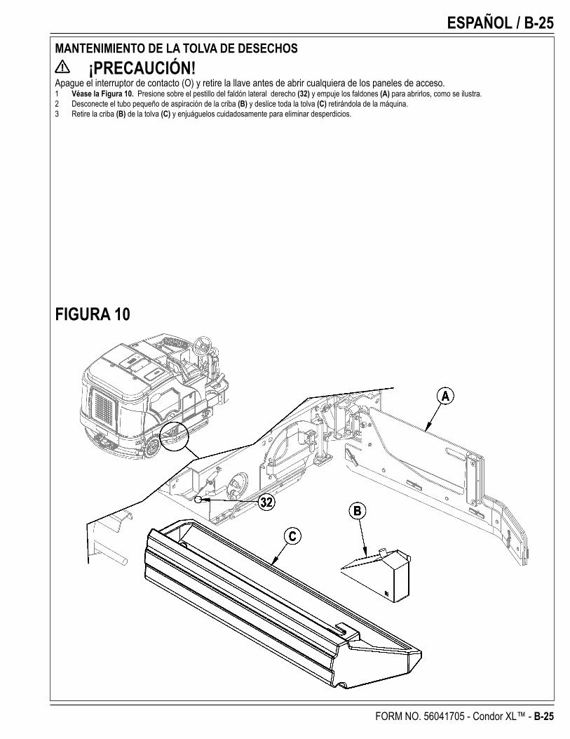
ESPAÑOL / B-25
FORM NO. 56041705 - Condor XL™ - B-25
MANTENIMIENTO DE LA TOLVA DE DESECHOS ¡PRECAUCIÓN!
Apague el interruptor de contacto (O) y retire la llave antes de abrir cualquiera de los paneles de acceso.1 Véase la Figura 10. Presione sobre el pestillo del faldón lateral derecho (32) y empuje los faldones (A) para abrirlos, como se ilustra.2 Desconecte el tubo pequeño de aspiración de la criba (B) y deslice toda la tolva (C) retirándola de la máquina.3 Retire la criba (B) de la tolva (C) y enjuáguelos cuidadosamente para eliminar desperdicios.
FIGURA 10
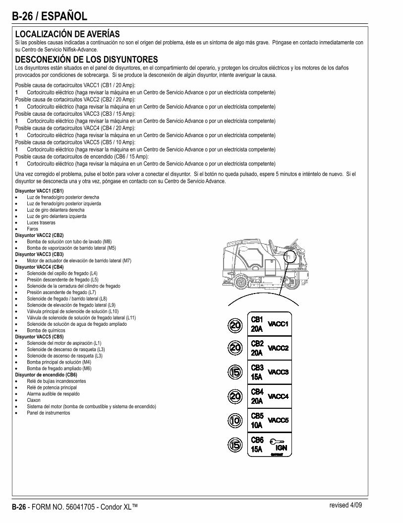
B-26 / ESPAÑOL
B-26 - FORM NO. 56041705 - Condor XL™
LOCALIZACIÓN DE AVERÍASSi las posibles causas indicadas a continuación no son el origen del problema, éste es un síntoma de algo más grave. Póngase en contacto inmediatamente con su Centro de Servicio Nilfi sk-Advance.
DESCONEXIÓN DE LOS DISYUNTORESLos disyuntores están situados en el panel de disyuntores, en el compartimiento del operario, y protegen los circuitos eléctricos y los motores de los daños provocados por condiciones de sobrecarga. Si se produce la desconexión de algún disyuntor, intente averiguar la causa.Posible causa de cortacircuitos VACC1 (CB1 / 20 Amp):1 Cortocircuito eléctrico (haga revisar la máquina en un Centro de Servicio Advance o por un electricista competente)Posible causa de cortacircuitos VACC2 (CB2 / 20 Amp):1 Cortocircuito eléctrico (haga revisar la máquina en un Centro de Servicio Advance o por un electricista competente)Posible causa de cortacircuitos VACC3 (CB3 / 15 Amp):1 Cortocircuito eléctrico (haga revisar la máquina en un Centro de Servicio Advance o por un electricista competente)Posible causa de cortacircuitos VACC4 (CB4 / 20 Amp):1 Cortocircuito eléctrico (haga revisar la máquina en un Centro de Servicio Advance o por un electricista competente)Posible causa de cortacircuitos VACC5 (CB5 / 10 Amp):1 Cortocircuito eléctrico (haga revisar la máquina en un Centro de Servicio Advance o por un electricista competente)Posible causa de cortacircuitos de encendido (CB6 / 15 Amp):1 Cortocircuito eléctrico (haga revisar la máquina en un Centro de Servicio Advance o por un electricista competente)Una vez corregido el problema, pulse el botón para volver a conectar el disyuntor. Si el botón no queda pulsado, espere 5 minutos e inténtelo de nuevo. Si el disyuntor se desconecta una y otra vez, póngase en contacto con su Centro de Servicio Advance.Disyuntor VACC1 (CB1)
Luz de frenado/giro posterior derecha Luz de frenado/giro posterior izquierda Luz de giro delantera derechaLuz de giro delantera izquierdaLuces traserasFaros
Disyuntor VACC2 (CB2)Bomba de solución con tubo de lavado (M8)Bomba de vaporización de barrido lateral (M5)
Disyuntor VACC3 (CB3)Motor de actuador de elevación de barrido lateral (M7)
Disyuntor VACC4 (CB4)Solenoide del cepillo de fregado (L4)Presión descendente de fregado (L5)Solenoide de la cerradura del cilindro de fregadoPresión ascendente de fregado (L7)Solenoide de fregado / barrido lateral (L8)Solenoide de elevación de fregado lateral (L9)Válvula principal de solenoide de solución (L10)Válvula de solenoide de solución de fregado lateral (L11)Solenoide de solución de agua de fregado ampliadoBomba de químicos
Disyuntor VACC5 (CB5)Solenoide del motor de aspiración (L1)Solenoide de descenso de rasqueta (L3)Solenoide de ascenso de rasqueta (L3)Bomba principal de solución (M4)Bomba de fregado ampliado (M6)
Disyuntor de encendido (CB6)Relé de bujías incandescentesRelé de potencia principalAlarma audible de respaldoClaxonSistema del motor (bomba de combustible y sistema de encendido)Panel de instrumentos
revised 4/09
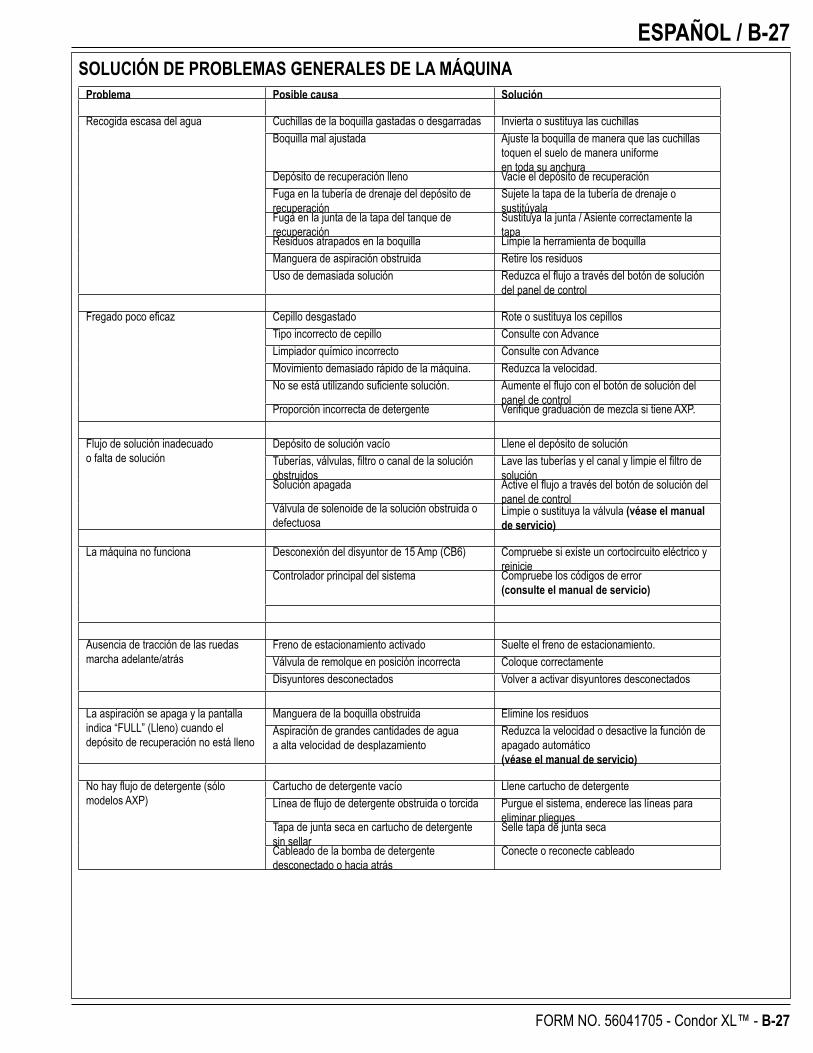
ESPAÑOL / B-27
FORM NO. 56041705 - Condor XL™ - B-27
SOLUCIÓN DE PROBLEMAS GENERALES DE LA MÁQUINAProblema Posible causa Solución
Recogida escasa del agua Cuchillas de la boquilla gastadas o desgarradas Invierta o sustituya las cuchillasBoquilla mal ajustada Ajuste la boquilla de manera que las cuchillas
toquen el suelo de manera uniformeen toda su anchura
Depósito de recuperación lleno Vacíe el depósito de recuperaciónFuga en la tubería de drenaje del depósito de recuperación
Sujete la tapa de la tubería de drenaje o sustitúyala
Fuga en la junta de la tapa del tanque de recuperación
Sustituya la junta / Asiente correctamente la tapa
Residuos atrapados en la boquilla Limpie la herramienta de boquillaManguera de aspiración obstruida Retire los residuosUso de demasiada solución Reduzca el fl ujo a través del botón de solución
del panel de control
Fregado poco efi caz Cepillo desgastado Rote o sustituya los cepillosTipo incorrecto de cepillo Consulte con AdvanceLimpiador químico incorrecto Consulte con AdvanceMovimiento demasiado rápido de la máquina. Reduzca la velocidad.No se está utilizando sufi ciente solución. Aumente el fl ujo con el botón de solución del
panel de controlProporción incorrecta de detergente Verifi que graduación de mezcla si tiene AXP.
Flujo de solución inadecuadoo falta de solución
Depósito de solución vacío Llene el depósito de soluciónTuberías, válvulas, fi ltro o canal de la solución obstruidos
Lave las tuberías y el canal y limpie el fi ltro de solución
Solución apagada Active el fl ujo a través del botón de solución del panel de control
Válvula de solenoide de la solución obstruida o defectuosa
Limpie o sustituya la válvula (véase el manual de servicio)
La máquina no funciona Desconexión del disyuntor de 15 Amp (CB6) Compruebe si existe un cortocircuito eléctrico y reinicie
Controlador principal del sistema Compruebe los códigos de error(consulte el manual de servicio)
Ausencia de tracción de las ruedas marcha adelante/atrás
Freno de estacionamiento activado Suelte el freno de estacionamiento.Válvula de remolque en posición incorrecta Coloque correctamenteDisyuntores desconectados Volver a activar disyuntores desconectados
La aspiración se apaga y la pantalla indica “FULL” (Lleno) cuando el depósito de recuperación no está lleno
Manguera de la boquilla obstruida Elimine los residuosAspiración de grandes cantidades de aguaa alta velocidad de desplazamiento
Reduzca la velocidad o desactive la función de apagado automático(véase el manual de servicio)
No hay fl ujo de detergente (sólo modelos AXP)
Cartucho de detergente vacío Llene cartucho de detergenteLínea de fl ujo de detergente obstruida o torcida Purgue el sistema, enderece las líneas para
eliminar plieguesTapa de junta seca en cartucho de detergente sin sellar
Selle tapa de junta seca
Cableado de la bomba de detergentedesconectado o hacia atrás
Conecte o reconecte cableado
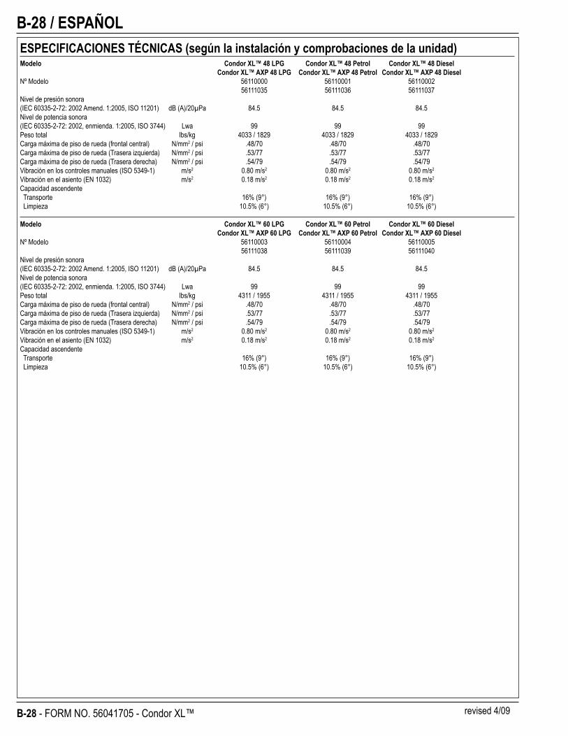
B-28 / ESPAÑOL
B-28 - FORM NO. 56041705 - Condor XL™
ESPECIFICACIONES TÉCNICAS (según la instalación y comprobaciones de la unidad)Modelo Condor XL™ 48 LPG Condor XL™ 48 Petrol Condor XL™ 48 Diesel Condor XL™ AXP 48 LPG Condor XL™ AXP 48 Petrol Condor XL™ AXP 48 DieselNº Modelo 56110000 56110001 56110002 56111035 56111036 56111037Nivel de presión sonora(IEC 60335-2-72: 2002 Amend. 1:2005, ISO 11201) dB (A)/20μPa 84.5 84.5 84.5Nivel de potencia sonora(IEC 60335-2-72: 2002, enmienda. 1:2005, ISO 3744) Lwa 99 99 99Peso total lbs/kg 4033 / 1829 4033 / 1829 4033 / 1829Carga máxima de piso de rueda (frontal central) N/mm2 / psi .48/70 .48/70 .48/70Carga máxima de piso de rueda (Trasera izquierda) N/mm2 / psi .53/77 .53/77 .53/77Carga máxima de piso de rueda (Trasera derecha) N/mm2 / psi .54/79 .54/79 .54/79Vibración en los controles manuales (ISO 5349-1) m/s2 0.80 m/s2 0.80 m/s2 0.80 m/s2
Vibración en el asiento (EN 1032) m/s2 0.18 m/s2 0.18 m/s2 0.18 m/s2
Capacidad ascendente Transporte 16% (9°) 16% (9°) 16% (9°) Limpieza 10.5% (6°) 10.5% (6°) 10.5% (6°)
Modelo Condor XL™ 60 LPG Condor XL™ 60 Petrol Condor XL™ 60 Diesel Condor XL™ AXP 60 LPG Condor XL™ AXP 60 Petrol Condor XL™ AXP 60 DieselNº Modelo 56110003 56110004 56110005 56111038 56111039 56111040Nivel de presión sonora(IEC 60335-2-72: 2002 Amend. 1:2005, ISO 11201) dB (A)/20μPa 84.5 84.5 84.5Nivel de potencia sonora(IEC 60335-2-72: 2002, enmienda. 1:2005, ISO 3744) Lwa 99 99 99Peso total lbs/kg 4311 / 1955 4311 / 1955 4311 / 1955Carga máxima de piso de rueda (frontal central) N/mm2 / psi .48/70 .48/70 .48/70Carga máxima de piso de rueda (Trasera izquierda) N/mm2 / psi .53/77 .53/77 .53/77Carga máxima de piso de rueda (Trasera derecha) N/mm2 / psi .54/79 .54/79 .54/79Vibración en los controles manuales (ISO 5349-1) m/s2 0.80 m/s2 0.80 m/s2 0.80 m/s2
Vibración en el asiento (EN 1032) m/s2 0.18 m/s2 0.18 m/s2 0.18 m/s2
Capacidad ascendente Transporte 16% (9°) 16% (9°) 16% (9°) Limpieza 10.5% (6°) 10.5% (6°) 10.5% (6°)
revised 4/09
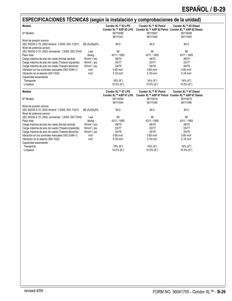
ESPAÑOL / B-29
FORM NO. 56041705 - Condor XL™ - B-29
ESPECIFICACIONES TÉCNICAS (según la instalación y comprobaciones de la unidad)Modelo Condor XL™ 62 LPG Condor XL™ 62 Petrol Condor XL™ 62 Diesel Condor XL™ AXP 62 LPG Condor XL™ AXP 62 Petrol Condor XL™ AXP 62 DieselNº Modelo 56110006 56110007 56110008 56111041 56111042 56111043Nivel de presión sonora(IEC 60335-2-72: 2002 Amend. 1:2005, ISO 11201) dB (A)/20μPa 84.5 84.5 84.5Nivel de potencia sonora(IEC 60335-2-72: 2002, enmienda. 1:2005, ISO 3744) Lwa 99 99 99Peso total lbs/kg 4311 / 1955 4311 / 1955 4311 / 1955Carga máxima de piso de rueda (frontal central) N/mm2 / psi .48/70 .48/70 .48/70Carga máxima de piso de rueda (Trasera izquierda) N/mm2 / psi .53/77 .53/77 .53/77Carga máxima de piso de rueda (Trasera derecha) N/mm2 / psi .54/79 .54/79 .54/79Vibración en los controles manuales (ISO 5349-1) m/s2 0.80 m/s2 0.80 m/s2 0.80 m/s2
Vibración en el asiento (EN 1032) m/s2 0.18 m/s2 0.18 m/s2 0.18 m/s2
Capacidad ascendente Transporte 16% (9°) 16% (9°) 16% (9°) Limpieza 10.5% (6°) 10.5% (6°) 10.5% (6°)
Modelo Condor XL™ 67 LPG Condor XL™ 67 Petrol Condor XL™ 67 Diesel Condor XL™ AXP 67 LPG Condor XL™ AXP 67 Petrol Condor XL™ AXP 67 DieselNº Modelo 56110009 56110010 56110015 56111044 56111045 56111046Nivel de presión sonora(IEC 60335-2-72: 2002 Amend. 1:2005, ISO 11201) dB (A)/20μPa 84.5 84.5 84.5Nivel de potencia sonora(IEC 60335-2-72: 2002, enmienda. 1:2005, ISO 3744) Lwa 99 99 99Peso total lbs/kg 4311 / 1955 4311 / 1955 4311 / 1955Carga máxima de piso de rueda (frontal central) N/mm2 / psi .48/70 .48/70 .48/70Carga máxima de piso de rueda (Trasera izquierda) N/mm2 / psi .53/77 .53/77 .53/77Carga máxima de piso de rueda (Trasera derecha) N/mm2 / psi .54/79 .54/79 .54/79Vibración en los controles manuales (ISO 5349-1) m/s2 0.80 m/s2 0.80 m/s2 0.80 m/s2
Vibración en el asiento (EN 1032) m/s2 0.18 m/s2 0.18 m/s2 0.18 m/s2
Capacidad ascendente Transporte 16% (9°) 16% (9°) 16% (9°) Limpieza 10.5% (6°) 10.5% (6°) 10.5% (6°)
revised 4/09