Embed Size (px)
Citation preview

31Eksploatacja i NiEzawodNosc – MaiNtENaNcE aNd REliability Vol.15, No. 1, 2013
Article citation info:
(*) Tekst artykułu w polskiej wersji językowej dostępny w elektronicznym wydaniu kwartalnika na stronie www.ein.org.pl
KrAwczyK M. conditions for Unmanned Aircraft reliability Determination. Eksploatacja i Niezawodnosc – Maintenance and reliability 2013; 15 (1): 31–36.
Mariusz KrAwczyK
Conditions for Unmanned airCraft reliability determination
Przesłanki determinUjąCe niezawodność samolotów bezPilotowyCh*
In the paper the required level of reliability is determined for several Unmanned Aerial Vehicles developed in Poland in order to get an achievement enabling these vehicles to operate within the Single European Sky. Calculations were made on the basis of an air crash model as well as the model capable to estimate the number of casualties resulting from an aircraft catastrophe. The provided examples allow us to specify Tactical and Technical Conditions pertaining in particular to the area of the operation of the aforementioned aircraft.
Keywords: Unmanned Aerial Vehicle, ground impact model, mid-air collisions model, hazard analysis.
W pracy wyznaczono niezbędną niezawodności kilku opracowanych w Polsce samolotów bezpilotowych, której osiągnięcie umoż-liwia ich eksploatacje w połączonej przestrzeni powietrznej. Obliczenia prowadzone były wg modelu katastrofy powietrznej oraz modelu pozwalającego na oszacowanie liczby ofiar na skutek rozbicia się samolotu. Podane przykłady pozwalają na sprecyzowa-nie Warunków Taktyczno – Technicznych, w szczególności dotyczących obszaru eksploatacji tychże samolotów.
Słowa kluczowe: samolot bezpilotowy, model zderzenia z ziemią, model kolizji powietrznej, analiza zagrożenia.
1. Introduction
The concept of an unmanned aerial vehicle (UAV) is not new as the first structures of this type were manufactured as early as in the First World War. In order to evaluate the current “scale of the phe-nomenon”, the easiest way to do it is a collective specification follow-ing the Jane’s Unmanned Aerial Vehicles and Targets catalogues that demonstrates that at the moment there are more than 400 UAVs and 120 flying targets that have been formally classified.
What makes their use in the public sector so rare if they show conspicuously identified advantages in terms of their use? One of the reasons is undoubtedly an insufficient level of reliability of current solutions that leads to a potentially unacceptably high probability of an accident or a catastrophe.
The basis for implementation of any UAV system for use in a civil and definitely in the Single European Sky (SES) in the future is a positive completion of a proper certification process. In the case of Europe, an entity that supervises actions of this type is EASA (the European Aviation Safety Agency) whose objective is to develop guidelines for a certification program referred to as CS (Certification Specifications). In the US market, a relevant certifying agency is the FAA (Federal Aviation Administration).
Pursuant to the assumptions adopted by the FAA and EASA [4] and [14], the UAV certification process, as assumed, is based on vast expertise and regulations that have been developed for civil aircraft, in particular, the guidelines for ensuring flying safety of civil aircraft in the following documents:
AMC 25-1309 for transportation aircrafts,•FAA AC 23 –1309-1C – for GA aircrafts.•
Allocation of a specific UAV to one of the classes (Tab. 1) as anticipated in the legislation. In involves a comparison of its kinetic energy with the average kinetic energy of aircraft of a given class. It is simultaneously assumed that the maximum kinetic energy of a UAV is calculated for two following scenarios:
A UAV lands in an unfamiliar area for unintended reasons, then a) its calculation speed is assumed to be 130% of the speed of at-traction in the configuration of landing;The control over a UAV is lost which results in its crashing, b) then its calculation speed is assumed to be 140% of the maxi-mum operating speed.
2. Catastrophic Events Involving UAVs
Apart from the economic issues related to a failure, downtime and finally with the destruction of an aircraft, the problem of a UAV catas-trophe may be considered from the perspective of ensuring the level of reliability of UAVs, in order:
to not exceed a critical probability of a catastrophe in the air a) κUAVkr , calculated for one hour of flight;in the event of its catastrophe featuring the probability equal b) σUAV , the ratio of third parties (on the surface) has not exceeded a critical value of γUAVkr , calculated into one hour of flight;
The values of κ and γ ratios have been adopted pursuant to a theory of controlling the risk [14], [6] stating that “Catastrophic conditions of damage must be extremely unlikely”. The critical value of κUAV is assumed to be (according to Table 1) a constant κUAVkr = 10-9, regard-less of the type of UAV – a perpetrator of a crash which is equivalent to the FAA and EASA recommendations of the maximum level of hazard of a civil aerial vehicle flying in SES. In order to determine the value of σUAVkr , Table 1 may be found useful because it specifies the figures of probability of an event subject to the class of a civil aerial vehicle [14]. A method that allows transformation of the contents of Table 1 to make it useful for a UAV, will be presented in a description of a model of catastrophe involving a crash of a UAV.
Exemplary calculations have been made for thirteen UAVs, in-cluding seven UAVs that are currently manufactured or designed in Poland and five manufactured abroad. The smallest MAV Black Wid-ow has a MTOW (Maximum Take-off Weight) of m = 60g, but for the largest Global Hawk m = 11 622kg. All UAV parameters required for

sciENcE aNd tEchNology
32 Eksploatacja i NiEzawodNosc – MaiNtENaNcE aNd REliability Vol.15, No. 1, 2013
calculations included in Table 2 where: S – is a surface of reference, SR – striking zone, εG – penetration ratio, a εA – a ratio used in a model of air crash.
3. Reliability of UAVs and a number of casualties among third parties
Assuming that the level of safety of use of UAVs in SES may not be lower than a value assumed for civil and military aircrafts, based on the regulations of FAR/CS 25 and 35 maximum ratio of casualties caused by the UAV crash, EASA suggests that one should assume γUAVkr = 10-6 which is a maximum of one casualty per million UAV flying hours.
Alternatively, in studies [8] and [14], authors assume the equiva-lence of the relation below, which seems to be more universal,
γ σUAV A Ckr kr= / (1)
i.e. the equality of a ratio of the number of casualties for a UAV and the probability of a loss of a civil aircraft as a result of an event of a catastrophic nature, according to the FAA, resulting in:
casualties among the crew and passengers;a) casualties among third parties;b) usually the loss of an aircraft.c)
Both approaches (assumptions) for UAV of a weight of m < 6 000lbs propelled by piston engine, lead to the following as-sumption γUAVkr = 10-6. For a bigger UAV or the ones with a turbine drive, in turn, these values will be smaller, according to the contents of Table 1.
The equation (1) may be transformed to the following,
σ σUAV A Ckr kr⋅ =Π / (2)
where: σUAVkr – probability of a catastrophe of a UAV, a Π – probabil-ity of casualties in case of a UAV crashing to the ground. Thus, having known (from Table 1) the value of σA/Ckr , determine the required criti-cal reliability of UAV, equal to
ReUAV UAVkr kr= −1 σ (3)
there is a necessity to calculate the probability of having casual-ties upon crashing with a UAV, according to the following model,
Π = ⋅ ⋅S DR Gε (4)
where: SR – is a striking zone characteristic of each of the UAVs in questions, D – population density in the area of a catastrophe, and εG is a so-called penetration ratio taking into account the mitigation of
Table 1. Probability of an event (according to EASA)
DocumentProbability of an event
10-3 10-4 10-5 10-6 10-7 10-8 10-9 below
FAA SSH P O E.O E.N
cS 25 P N E.N
cS 23
clas
s
IV P O E.O E.N
III P O E.O E.N
II P O E.O E.N
I P O E.O E.N
P – Likely ; O – Remote; E.O – Extremely remote; N – Unlikely; E.N – Extremely unlikely.Class I Typical with a piston engine below 6000lbs,Class II – Piston multi-engines or turbine engines below 6000lbs,Class III Typical with piston engine, piston multi-engines or turbine multi-engine above 6000lbs,Class IV – Commuter category.
Table 2. Calculation parameters of exemplary UAVs
ref. UAV MTOw [kg] S[m2]
SR[m2] εG εA
1 Global Hawk 11622 50.00 546.00 0.93 1
2 Predator 1 021 13.50 51.00 0.58 1
3 czajka 473 10.20 21.94 0.21 1
4 Pheonix 270 56.80 3.31 0.09 1
5 Shadow 200 159 2.99 12.00 0.24 1
6 Samonit 2 50 2.05 3.20 0.13 0.5
7 OcP Jet 40 1.10 3.59 0.18 0.4
8 SMcP Szerszeń 39 1.82 2.48 0.12 0.39
9 MJ-7 Szogun 29 1.11 2.33 0.13 0.29
10 SMcP Komar 25 1.10 1.92 0.12 0.25
11 FlyEye 11 0.95 0.71 0.10 0.11
12 Mini 4.36 0.60 0.28 0.09 0.043
13 Black widow 0.06 0.03 0.01 0.06 0.0006

sciENcE aNd tEchNology
33Eksploatacja i NiEzawodNosc – MaiNtENaNcE aNd REliability Vol.15, No. 1, 2013
the effects of a catastrophe if potential victims are, e.g. in buildings that provide some shelter to them. The size of the striking zone is determined by means of an empirical relation below
S mSR = ⋅
0 028
2 3.
/ (5)
where: m – is a weight of UAV determined [4] on the assumption that it is proportional to the energy of an aircraft at the moment of crash, made up mainly of its kinetic energy and the fuel explosion energy. The SR figures for the analysed UAVs are presented in Table 2 and Figure 1 presents them for the GA (General Aviation and Transporta-tion) aircraft subject to a ballistic ratio β determined pursuant to the following relation where cx is a resistance force ratio.
β =⋅
mc Sx
(6)
A precise determination of a striking zone is of the utmost impor-tance (linear dependency) for the precision of a model of the UAV catas-trophe, for obvious reasons. Thus, an attempt was made to verify relation (5) involving a comparison of the real spot of the Tu 154M’s catastrophe of 10 April 2010 in the vicinity of the Severny airport near Smolensk shown in Figure 2 with a value calculated according to relation (5). Assuming the data from Jane’s catalogue, the calculation value SR for Tu 154M aircraft is SR = 3 788m2. By calculation using a satellite image of the crash spot, we arrive at the following: SR ≈ 150×25 = 3 750m2 which verifies relation (5) in a positive manner.
For the analysis of UAV system design, it is also useful to deter-mine its reliability defined by the following relation,
ReUAV
tMTBCF
kre=
−
(7)
where, MTBCF is the Mean Time Between Critical Failure. A reverse of MTBCF is a number of defects (or a set of defects) of an UAV ex-pected within an hour that would lead to a catastrophe.
A presented model of an assessment of the risk level imposed potentially by UAV for the third parties was subject to a model ex-periment that produced the following results specified in collective Table 3. Three various mission scenarios were taken into account:
flight between the EPMO airport located near Modlin, and a) EPSO located in the vicinity of Sochaczew. The flight route presented in Figure 2 of the total approximate length of L = 38km crosses three administrative districts: Nowy Dwór (L1 = 24,5km), Warsaw West (L2 = 5,5km) and Sochaczew (L3 = 8km) which feature a population density of 61 – 103 60 persons per 1km2 respectively;
patrol mission in equal shares (25% each) over four suburbs b) of the Capital City of Warsaw featuring the highest population density defined as the number of inhabitants per 1km2, Ocho-ta (D1=9215),Śródmieście(D2 = 8 120), Wola (D3 = 7 149) and Mokotów (D4 = 6 372);patrol mission in equal shares (25% each) over four sub-c) urbs of the Capital City of Warsaw featuring the lowest population density defined as the number of inhabitants per 1km2Białołęka (D1 = 1 222), Bielany (D2 = 4 142), Be-mowo (D3 =4532)andŻoliborz(D4 = 5 654).
An order of UAVs in Table 3 is determined by their weight. The heaviest aircraft are at the beginning of the specification, and the lightest are at the end. It is clear that, as expected, the requirements pertaining to the reliability of UAVs usually reduce in proportion to their weight. Two UAVs are exceptions to the rule: no. 4 being stratospheric Phoenix and No. 7 an aerial target featuring a jet en-gine OCP – Jet. Through analysis of the contents of Table 3 we find that for a large Phoenix aircraft featuring a wing span of 38.2m the requirements pertaining to its minimum reliability are significantly lower than the ones determined for an obviously smaller Czajka air-
Fig.1. A size of a striking zone for the selected UAVs, Gas and Transpira-tion
Fig. 2. Crash spot of the Tu 154M aircraft (Severny)
Fig. 3. A penetration ratio subject to a ballistic ratio
Fig. 4. Flight route between EPMO and EPSO
sciENcE aNd tEchNology
34 Eksploatacja i NiEzawodNosc – MaiNtENaNcE aNd REliability Vol.15, No. 1, 2013
craft. A reason for these facts is the relative small ballistic ratio of the Phoenix aircraft that gives, in turn, a small penetration ratio and a minimum relation of weight to the reference surface resulting in an exceptionally low (compared to the size of an aircraft) striking zone. Similar substantive reasons (mainly a relatively high penetration ra-tio) make the requirements pertaining to the minimum reliability of a smaller OCP-Jet aircraft featuring a relatively contained design higher than those of the larger and heavier Samonit – 2 UAV.
4. Reliability of the UAV and the risk of a collision in the air
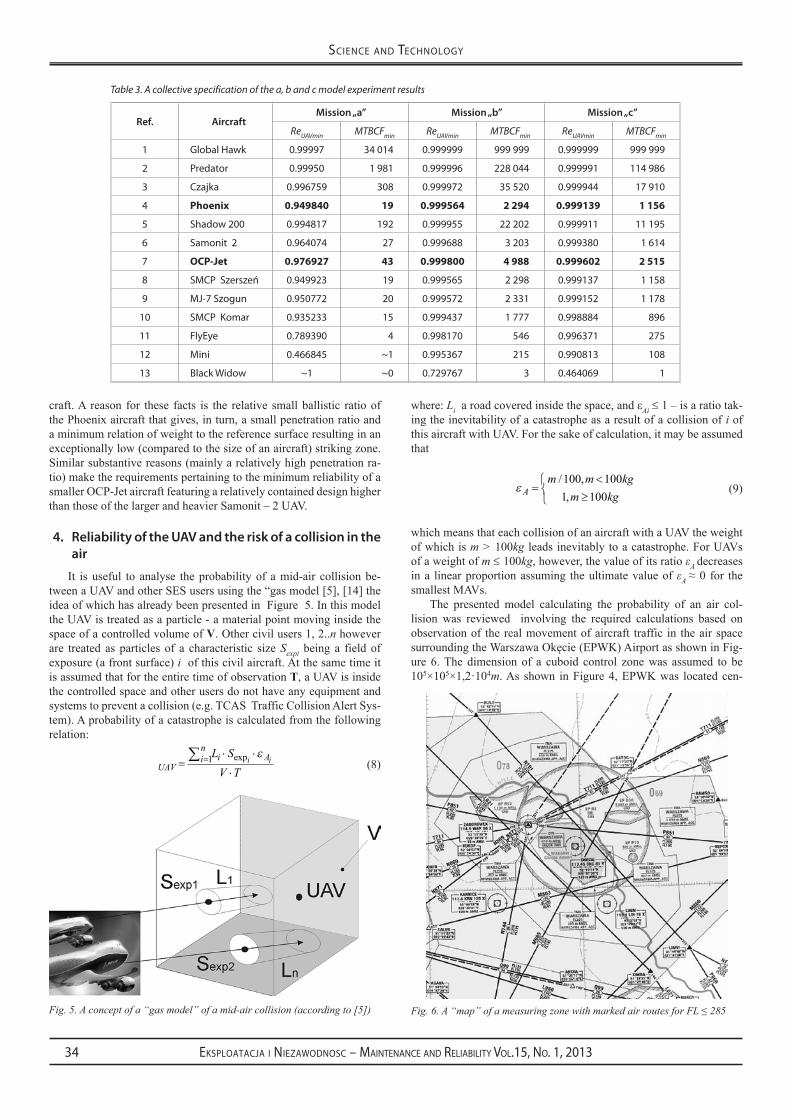
It is useful to analyse the probability of a mid-air collision be-tween a UAV and other SES users using the “gas model [5], [14] the idea of which has already been presented in Figure 5. In this model the UAV is treated as a particle - a material point moving inside the space of a controlled volume of V. Other civil users 1, 2..n however are treated as particles of a characteristic size Sexpi being a field of exposure (a front surface) i of this civil aircraft. At the same time it is assumed that for the entire time of observation T, a UAV is inside the controlled space and other users do not have any equipment and systems to prevent a collision (e.g. TCAS Traffic Collision Alert Sys-tem). A probability of a catastrophe is calculated from the following relation:
UAVin
i AL SV T
i i=⋅ ⋅
⋅=∑ 1 exp ε
(8)
where: Liaroadcoveredinsidethespace,andεAi ≤ 1 – is a ratio tak-ing the inevitability of a catastrophe as a result of a collision of i of this aircraft with UAV. For the sake of calculation, it may be assumed that
ε Am m kg
m kg=
<≥
/ ,,100 1001 100
(9)
which means that each collision of an aircraft with a UAV the weight of which is m ˃ 100kg leads inevitably to a catastrophe. For UAVs of a weight of m ≤ 100kg, however, the value of its ratio εA decreases in a linear proportion assuming the ultimate value of εA ≈ 0 for the smallest MAVs.
The presented model calculating the probability of an air col-lision was reviewed involving the required calculations based on observation of the real movement of aircraft traffic in the air space surroundingtheWarszawaOkęcie(EPWK)AirportasshowninFig-ure 6. The dimension of a cuboid control zone was assumed to be 105×105×1,2·104m.As shown inFigure4,EPWKwas locatedcen-
Table 3. A collective specification of the a, b and c model experiment results
Ref. AircraftMission „a” Mission „b” Mission „c”
ReUAVmin MTBCFmin ReUAVmin MTBCFmin ReUAVmin MTBCFmin
1 Global Hawk 0.99997 34 014 0.999999 999 999 0.999999 999 999
2 Predator 0.99950 1 981 0.999996 228 044 0.999991 114 986
3 czajka 0.996759 308 0.999972 35 520 0.999944 17 910
4 Phoenix 0.949840 19 0.999564 2 294 0.999139 1 156
5 Shadow 200 0.994817 192 0.999955 22 202 0.999911 11 195
6 Samonit 2 0.964074 27 0.999688 3 203 0.999380 1 614
7 oCP-jet 0.976927 43 0.999800 4 988 0.999602 2 515
8 SMcP Szerszeń 0.949923 19 0.999565 2 298 0.999137 1 158
9 MJ-7 Szogun 0.950772 20 0.999572 2 331 0.999152 1 178
10 SMcP Komar 0.935233 15 0.999437 1 777 0.998884 896
11 FlyEye 0.789390 4 0.998170 546 0.996371 275
12 Mini 0.466845 ~1 0.995367 215 0.990813 108
13 Black widow ~1 ~0 0.729767 3 0.464069 1
Fig. 5. A concept of a “gas model” of a mid-air collision (according to [5]) Fig. 6. A “map” of a measuring zone with marked air routes for FL ≤ 285

sciENcE aNd tEchNology
35Eksploatacja i NiEzawodNosc – MaiNtENaNcE aNd REliability Vol.15, No. 1, 2013
trally relative to the base of the zone. The air traffic observations were performed for two morning peak hours between 700 ÷ 900 on 29th Feb-ruary 2012. At that time, there were 30 aircraft in the zone altogether. 10ofthemtookofffromEPWK,7landedthereand15crossedthezone at various FL (Flight Level) out of which 6 were performing a transit flight at FL 340. The altitude and speed of the flight as well as the length of the route covered by a given aircraft inside the measur-ing zone were recorded. Each of the observed aircraft was identified, which made it possible to determine its exposure zone of Sexp based on the catalogue data.
The completed calculations and registrations made it possible to determine the probability of an air collision according to relation (8) with one of the UAVs that are present there (calculations were made for each of the UAVs from Table 3). In particular, four scenarios were assumed for the calculations presented in Table 4 in which a UAV hypothetically moved regardless of their operating parameters over the entire time of observation of the UAV:
inside the entire measurement zone;a) below b) FL 160 (aircrafts taking off and landing);on the top flying route at c) FL 340;on the descending route starting from 10d) NM.
While analysing the calculation results presented in Table 4, it is obvious, that apart from a very small Black Widow the remain-ing UAVs pose a real, unacceptably high risk to current air traffic; this assumption is made pursuant to the model that they move in an uncontrolled manner in SES. The value of probability of occurrence of an air catastrophe involving a UAV strongly depends on the space in which a flight is performed. The probability of collision is defi-nitely higher in the area of an approach to airports on pre-determined air routes. In the remaining areas, this likelihood is much lower but remains at the level recommended by FAA/EASA of 10-9 of catastro-phes per one hour of flight.
Integration of UAV systems with SES requires development of new methods to protect the air traffic safety in terms of air collision, prevention and minimising the number of potential victims among third parties arising from a crash of an UAV.
The aforementioned models (of collision and crash of UAV) pro-vide an effective tool for establishing the specified tasks.
In particular, The UAV Crash Model makes it possible to deter-mine the required level of reliability of the entire UAV system in re-spect of ensuring the required level of safety related to the risk posed by a UAV in the event of its catastrophe, for third parties. While ana-lysing the model, it is easy to notice that UAVs that are bigger and that move faster must be more reliable than MAVs, the potential risk of which is relatively low. The expected operating area also plays a major role. UAVs designed for operation in major urban agglomera-tions must definitely be more reliable compared to the ones used e.g. for patrolling of borders along which the population density is usually low.
5. Conclusions
Presented model indicates severe challenges for designers of ma-jor UAVs for which the total required MTBCF is comparable to the time of defects of a simple electronic (!) e.g. a simple fuse used in military aircrafts. Simple measures improving the reliability of these aircraft e.g.: application of the selected, top quality elements or redun-dancy of critical systems appears to be insufficient. Thus, it is prob-ably a reason why decision-making entities (EASA, FAA) consider an option to implement a principle of permanent monitoring of UAV by a surface operator with an option of overtake of control as a matter of emergency in critical situations. On the one hand such solution im-poses more stringent requirements pertaining to communication e.g. high reliability, short transmission delay or resistance to disturbance and on the other hand, it redefines a checklist of critical events that used to be classified as catastrophic for UAVs (i.e. shortens it).
A mid-air collision model is a sufficient premise for the develop-ment of special ATM (Air Traffic Management) procedures dedicated for UAVs and to integrate them with avionic systems of the equip-ment preventing air collisions e.g. TCAS (Traffic Collision Avoid-ance System). This model also shows that the reliability of systems preventing air collisions of these UAVs that according to assumptions are expected to move only in the areas of an approach to airports or on air routes must be higher than the ones designated to be used above an area designated for civil flights (HALE aircrafts) or operating locally at very low altitudes where there is practically no air traffic.
Table 4. A collective specification of results of the a, b, c and d model experiment
Ref. Aircraft Mission „a”κUAVV
Mission „b”κUAVFL<160
Mission „c”κUAVFL=340
Mission „d”κUAVLANDING
1 Global Hawk 3.99E-7 3.83E-7 2.14E-5 0.943
2 Predator 3.99E-7 3.83E-7 2.14E-5 0.943
3 czajka 3.99E-7 3.83E-7 2.14E-5 0.943
4 Phoenix 3.99E-7 3.83E-7 2.14E-5 0.943
5 Shadow 200 3.99E-7 3.83E-7 2.14E-5 0.943
6 Samonit – 2 2.00E-7 1.91E-7 1.05E-5 0.472
7 OcP – Jet 1.60E-7 1.53E-7 0.88E-5 0.377
8 SMcP – Szerszeń 1.56E-7 1.49E-7 0.82E-5 0.368
9 MJ-7 Szogun 1.16E-7 1.11E-7 0.61E-5 0.274
10 SMcP – Komar 0.98E-7 0.95E-7 0.53E-5 0.236
11 FlyEye 0.44E-7 0.42E-7 0.23E-5 0.104
12 Mini 0.17E-7 0.17E-7 0.09E-5 0.041
13 Black widow 0.002e-7 0.002e-7 0.01E-5 0.0004
Acknowledgement: The research work was financed from the funds of the Ministry of Science and Higher Education OR00011611 project.

sciENcE aNd tEchNology
36 Eksploatacja i NiEzawodNosc – MaiNtENaNcE aNd REliability Vol.15, No. 1, 2013
References
Boeing. Statistical Summary of Commercial Jet Airplane Accidents Worldwide Operations 1959 – 2008. 2009.1. Columbia Accident Investigation Board. Determination of Debris Risk to the Public, Due to the Columbia Breakup During Reentry. Report 2. Volume II 2003.DeGarmo M.T. Issues Concerning Integration of Unmanned Aerial Vehicles in Civil Airspace.Center for Advanced Aviation System 3. Development 2004.EASA. Advance -notice of proposed amendment (NPA) No 16/2005.4. Endoh S. Aircraft Collision Models, M.S Thesis. Department of Aeronautics and Astronautics, Massachusetts Institute of Technology, 5. Cambridge 1982.FAA. System safety analysis and assessment for part 23 airplanes. AC No: 23.1309-1D, 2009.6. GorajZ,FrydrychewiczA,ŚwitkiewiczR,HernikB, J.GadomskJ,Goetzendorf-GrabowskiT,FigatM,SuchodolskiS,ChajecW.High7. altitude long endurance unmanned aerial vehicle of a new generation – a design challenge for a low cost, reliable and high performance aircraft. Bulletin of the Polish Academy of Sciences 2004; Technical sciences, vol. 52, no. 3.KingD.W,BertapelleA,MosesC.UAVfailure ratecriteria for equivalent levelof safety, InternationalHelicopterSafetySymposium,8. Montréal 2005.MurrayD.P.ATieredApproachtoFlightSafetyAnalysis.Keystone2006.9. OfficeoftheSecretaryofDefence.AirspaceIntegrationPlanforUnmannedAviation,2004.10. Pettit D, Turnbull A. General Aviation Aircraft Reliability Study, Hampton 2002; NASA/CR-2001-210647.11. PrażewskaM.Niezawodnośćurządzeńelektronicznych.WKiŁWarszawa1987.12. Tsach S, Penn D, Levy A. Advanced technologies and approaches for next generation UAVS. 23rd Congress of International Council of the 13. Aeronautical Sciences Toronto 2002.Weibel R.E, Hansman R.J. Safety considerations for operation of UAVs in the NAS; Report No. ICAT-2005-1March 2005.14.
mariusz krawCzyk, Ph. d. centre of New TechnologiesInstitute of AviationAl. Krakowska 110/114, 02-256 warszawa, PolandE-mail: [email protected]

dr inż. Mariusz Krawczyk
Centrum Nowych Technologii, Instytut Lotnictwa Al.Krakowska 110/114, 02-256 Warszawa, Polska E-mail: [email protected]
Przesłanki determinujące niezawodność samolotów bezpilotowych
Słowa kluczowe: samolot bezpilotowy, model zderzenia z ziemią, model kolizji powietrznej,
analiza zagrożenia
Streszczenie: W pracy wyznaczono niezbędną niezawodności kilku opracowanych w Polsce
samolotów bezpilotowych, której osiągnięcie umożliwia ich eksploatacje w połączonej przestrzeni
powietrznej. Obliczenia prowadzone były wg modelu katastrofy powietrznej oraz modelu
pozwalającego na oszacowanie liczby ofiar na skutek rozbicia się samolotu. Podane przykłady
pozwalają na sprecyzowanie Warunków Taktyczno – Technicznych, w szczególności dotyczących
obszaru eksploatacji tychże samolotów.
1. Wstęp
Idea samolotu bezpilotowego (UAV) nie jest nowa, jako że pierwsze tego typu
konstrukcje powstały już w okresie I wojny światowej. Aby właściwie ocenić obecną „skalę
zjawiska” najłatwiej przytoczyć zbiorcze zestawienie za katalogiem Jane’s Unmanned Aerial
Vehicles and Targets, z którego wynika, że w chwili obecnej oficjalnie sklasyfikowanych jest
przeszło 400 UAV oraz 120 celów latających.
Co powoduje zatem, że przy wyraźnie zidentyfikowanych walorach użytkowych
systemów UAV, ich wykorzystanie w sektorze publicznym jest tak sporadyczne? Jedną z
przyczyn jest niewątpliwie niewystarczający poziom niezawodności obecnych rozwiązań,
niosący potencjalnie nieakceptowalnie wysokie prawdopodobieństwa wystąpienia wypadku,
czy katastrofy.
Podstawą wdrożenia któregokolwiek systemu UAV do użytkowania w cywilnej, a w
przyszłości zapewne połączonej przestrzeni powietrznej (Single European Sky – SES) jest
pozytywne przeprowadzenie właściwego procesu certyfikacji. W przypadku Europy jednostką
nadzorującą tego typu działania jest EASA (European Aviation Safety Agency), której
zadaniem jest także opracowanie wytycznych programu certyfikacji zwanych CS
(Certification Specifications). Dla rynku amerykańskiego właściwą jednostką certyfikującą
będzie natomiast FAA (Federal Aviation Administration).
Proces certyfikacji UAV zgodnie z założeniami przyjętymi przez FAA i EASA
[12], [8], z założenia bazuje na obszernej wiedzy i przepisach jakie opracowano dla
samolotów cywilnych. W szczególności wytyczne dla zapewnienia bezpieczeństwa lotu
samolotów cywilnych zawarto w następujących dokumentach:
AMC 25-1309 - dla samolotów transportowych,
FAA AC 23 –1309-1C – dla samolotów GA.
Przypisania konkretnego UAV do jednej z przewidzianych przepisami klas (Tab.1).
Polega na porównaniu jego energii kinetycznej ze średnią energią kinetyczną samolotów

wchodzących w skład danej klasy. Zakłada się przy tym, że maksymalna energia kinetyczna
UAV obliczana jest dla dwóch następujących scenariuszy:
a. UAV z niezamierzonych przyczyn ląduje awaryjnie w terenie przygodnym – wtedy
za jego prędkość obliczeniową przyjmuje się jako 130% prędkości przeciągnięcia w
konfiguracji do lądowania;
b. Następuje utrata kontroli nad UAV, co prowadzi do jego rozbicia - wtedy za jego
prędkość obliczeniową przyjmuje się 140% maksymalnej prędkości operacyjnej;
2. Katastrofalne zdarzenia z udziałem UAV
Pomijając kwestie ekonomiczne związane z awarią, przestojem, czy w ostateczności
ze zniszczeniem samolotu, problem katastrofy UAV można rozpatrywać w aspektach
zapewnienia takiego poziomu niezawodności UAV aby:
a. nie przekroczyć krytycznego prawdopodobieństwa katastrofy w powietrzu UAVkr ,
w przeliczeniu na jedną godzinę lotu;
b. w przypadku jego katastrofy z prawdopodobieństwem równym UAV , wskaźnik
ofiar trzecich (na ziemi) nie przekroczył krytycznej wartości UAVkr , w przeliczeniu
na jedną godzinę lotu;
Wartości liczbowe współczynników i przyjęte został zgodnie z teorią sterowania
ryzykiem [8], [13] mówiącą, że „Katastrofalne warunki uszkodzenia muszą być skrajnie
nieprawdopodobne”. Wartość krytyczną UAV przyjmuje się zatem (wg Tab.1) jako
stałą - UAVkr = 10-9
, niezależnie od typu UAV – sprawcy zderzenia, co jest tożsame z
zaleceniami FAA i EASA odnośnie maksymalnego poziomu ryzyka wystąpienia katastrofy
cywilnego statku powietrznego poruszającego się w SES. Natomiast do określenia wartości
UAVkr , przydatna jest Tab.1, w której zestawiono wartości liczbowe prawdopodobieństwa
wystąpienia zdarzenia w zależności od klasy cywilnego statku powietrznego [8]. Metoda
pozwalająca na transformacje zawartości Tab.1, tak aby była ona użyteczna dla UAV
zaprezentowana zostanie w opisie modelu katastrofy polegającej na rozbiciu się UAV.
Tabela 1. Prawdopodobieństwa wystąpienia zdarzenia (wg EASA).
P – Prawdopodobne; O – Odległe; E.O – Ekstremalnie Odległe; N – Nieprawdopodobne; E.N – Ekstremalnie Nieprawdopodobne.
Klasa I - typowe z silnikiem tłokowym, poniżej 6000lbs, Klasa II – wielosilnikowe tłokowe lun turbinowe, poniżej 6000lbs,
Klasa III - typowe z silnikiem tłokowym, wielosilnikowe tłokowe lub turbinowe, powyżej 6000lbs,
Klasa IV – Kategoria Commuter.
Przykładowe obliczenia wykonano dla trzynastu UAV, w tym siedmiu
produkowanych lub obecnie projektowanych w Polsce, oraz pięciu produkcji zagranicznej.
Najmniejszy MAV Black Widow ma MTOW (Maximum Take-off Weight) m = 60g,
natomiast największy Global Hawk m = 11 622kg. Wszystkie niezbędne do wykonania
Dokument Prawdopodobieństwo zdarzenia
10-3
10-4
10-5
10-6
10-7
10-8
10-9
poniżej
FAA SSH P O E.O E.N
CS 25 P N E.N
CS 23
Kla
sa
IV P O E.O E.N
III P O E.O E.N
II P O E.O E.N
I P O E.O E.N

obliczeń parametry UAV zamieszczono w Tab.2, gdzie: S - stanowi jego powierzchnia
odniesienia, SR – pole rażenia, G – współczynnik penetracji, a A – współczynnik
wykorzystywany w modelu katastrofy powietrznej.
Tabela 2. Parametry obliczeniowe przykładowych UAV
Lp. UAV MTOW
[kg] S
[m2]
SR
[m2]
G A
1 Global Hawk 11 622 50,00 546,00 0,93 1
2 Predator 1 021 13,50 51,00 0,58 1
3 Czajka 473 10,20 21,94 0,21 1
4 Pheonix 270 56,80 3,31 0,09 1
5 Shadow 200 159 2,99 12,00 0,24 1
6 Samonit - 2 50 2,05 3,20 0,13 0,5
7 OCP - Jet 40 1,10 3,59 0,18 0,4
8 SMCP - Szerszeń 39 1,82 2,48 0,12 0,39
9 MJ-7 Szogun 29 1,11 2,33 0,13 0,29
10 SMCP - Komar 25 1,10 1,92 0,12 0,25
11 FlyEye 11 0,95 0,71 0,10 0,11
12 Mini 4,36 0,60 0,28 0,09 0,043
13 Black Widow 0,06 0,03 0,01 0,06 0,0006
3. Niezawodność UAV, a liczba ofiar wśród osób trzecich
Zakładając, że poziom bezpieczeństwa użytkowania UAV w SES nie może być niższy
od przyjętego dla samolotów cywilnych i maszyn wojskowych, niejako arbitralnie EASA
opierając się na przepisach FAR/CS 25 i 35 maksymalny wskaźnik ofiar z powodu rozbicia
UAV proponuje przyjąć na UAVkr = 10-6
, co stanowi maksymalnie jedną ofiarę przypadającą na
milion godzin lotów UAV.
Alternatywnie, co wydaje się podejściem bardziej uniwersalnym, w opracowaniach [4]
i [8] ich autorzy zakładają tożsamość,
(1)
tj. równości wskaźnika ilości ofiar dla UAV i prawdopodobieństwa utraty samolotu
cywilnego na skutek wystąpienia zdarzenia o charakterze katastrofalnym, dla przypomnienia
wg FAA skutkujących:
a. Ofiarami wśród załogi i pasażerów;
b. Ofiarami wśród osób trzecich;
c. Zwykle utratą samolotu.
Oba podejścia (założenia), dla UAV o masie m < 6 000lbs napędzie tłokowym,
prowadzą do przyjęcia UAVkr = 10-6 .Dla UAV większych albo z napędem turbinowym natomiast,
wartości te będą mniejsze, zgodne z zawartością Tab.1. Tożsamość (1) przekształcić można do następującej postaci,
(2)

gdzie: UAVkr – prawdopodobieństwo katastrofy UAV, a – prawdopodobieństwo wystąpienia
ofiar, w przypadku uderzenia UAV w ziemię. Aby zatem znając (z Tab.1) wartość A/Ckr
wyznaczyć wymaganą niezawodność krytyczną UAV, równą
(3)
niezbędne jest obliczenie prawdopodobieństwa wystąpienia ofiar po zderzeniu z UAV z
ziemią, wg następującego modelu,
(4)
gdzie: SR – jest polem rażenia, charakterystycznym dla każdego z rozpatrywanych UAV,
D – gęstością zaludnienia w rejonie katastrofy, a G – stanowi tzw. współczynnik penetracji
uwzgledniający osłabienia skutków katastrofy, jeśli potencjalne ofiary przebywają np. w
budynkach stanowiących dla nich rodzaj schronu. Wielkość strefy rażenia wyznacza się z
zależności empirycznej,
(
)
(5)
gdzie: m – masa UAV, wyprowadzonej [12] przy założeniu, że jest ona proporcjonalna do
energii jaką samolot posiada w chwili zderzenia, na która składa się głównie jego energia
kinetyczna oraz energia eksplozji paliwa. Wartości liczbowe SR dla analizowanych UAV
zamieszczono w Tab.2, natomiast na rys.1 zaprezentowano je dla samolotów GA (General
Aviation i Transportowych), w zależności od współczynnika balistycznego wyznaczanego
zgodnie z wyrażeniem, gdzie cx – stanowi współczynnik siły oporu.
(6)
Rys.1. Wielkość strefy rażenia dla wybranych samolotów UAV, GA i Transportowych
Dokładność metody wyznaczenia strefy rażenia z oczywistych względów ma
kolosalne znaczenie (zależność liniowa) dla dokładności modelu katastrofy UAV. Dlatego też
podjęto próbę weryfikacji zależności (5), polegającej na porównaniu rzeczywistego,
pokazanego na rys. 2 miejsca katastrofy z 10 kwietnia roku 2010 samolotu Tu - 154M w
pobliżu lotniska Sewiernyj pod Smoleńskiem, z wartością wyliczoną wg zależności (5).
Przyjmując dane za katalogiem Janes’a wartość obliczeniowa SR dla samolotu Tu - 154M
10 100 1000 10000
[kg/m2
]
1
10
100
1000
10000
100000
SR [m
2]
A340B787
B747
A320A319B737
F70 DHC8ERJ145
JS45CS500CE404
PA60PA34
BC35
DA40Zlin
CN235
VLA1CE150
CzajkaVLA2
ULM1
ULM2
Ax AirbusBx BoeingBC BeechcraftCEx CessnaCN CasaDA DiamondDH DeHavillandERJ EmbraerPAx PiperVLAx Very Light A/CULMx Ultralight

wynosi SR = 3 788m2. Dokonując obliczeń na zdjęciu satelitarnym miejsca katastrofy otrzymujemy
natomiast SR ≈ 150×25 = 3 750m2, co pozytywnie weryfikuje zależność (5).
Rys. 2. Miejsce katastrofy samolotu Tu - 154M (Sewiernyj)
Wartość współczynnika penetracji natomiast dobierana jest, ze sporządzonego w
oparciu o dane statystyczne, zamieszczone w [8] wykresu zaprezentowanego na rys.3.
Rys.3. Współczynnik penetracji w zależności od współczynnika balistycznego
Dla potrzeb analizy projektowania systemów UAV przydatne jest także określenie
jego niezawodności danej zależnością,
(7)
gdzie, MTBCF oznacza Mean Time Between Critical Failure. Odwrotnością MTBCF jest
oczekiwana w przeciągu godziny ilość uszkodzeń (lub zespołu uszkodzeń) systemu UAV
prowadzących w konsekwencji do katastrofy.
Przedstawiony model oceny stopnia zagrożenia jakie potencjalnie UAV stanowi dla
osób trzecich poddano eksperymentowi modelowemu, w wyniku którego otrzymano
następujące, zamieszczone w tabeli zbiorczej Tab.3, wyniki. W szczególności rozważano trzy
następujce scenariusze misji:
10 100 1000 10000
[kg/m2]
0%
20%
40%
60%
80%
100%
G

a. Przelot pomiędzy lotniskiem EPMO położonym niedaleko Modlina, a EPSO
zlokalizowanym w okolicach Sochaczewa. Zaprezentowana na rys. 2 trasa
przelotu o łącznej długości ok. L = 38km przebiega nad trzema powiatami:
nowodworskim (L1 = 24,5km), warszawskim - zachodnim (L2 = 5,5km) oraz
sochaczewskim (L3 = 8km), w których gęstość zaludnienia stanowi odpowiednio
61 – 103 - 60 osób na 1km2.
Rys.4. Trasa przelotu pomiędzy EPMO, a EPSO
b. Misja patrolowa, w równych udziałach (po 25%) nad czterema dzielnicami Miasta
Stołecznego Warszawy, charakteryzującymi się największą gęstością zaludnienia,
zdefiniowana jako liczba mieszkańców przypadająca na 1km2
Ochoty (D1 = 9 215), Śródmieścia (D2 = 8 120), Woli (D3 = 7 149) i
Mokotowa (D4 = 6 372);
c. Misja patrolowa, w równych udziałach (po 25%) nad czterema dzielnicami Miasta
Stołecznego Warszawy, charakteryzującymi się najmniejszą gęstością
zaludnienia, zdefiniowana jako liczba mieszkańców przypadająca na 1km2,
Białołęki (D1 = 1 222), Bielan (D2 = 4 142), Bemowa (D3 = 4 532) i
Żoliborza (D4 = 5 654);
Tabela 3. Zbiorcze zestawienie wyników eksperymentu modelowego a, b oraz c
Lp. Samolot Misja „a” Misja „b” Misja „c”
ReUAVmin MTBCFmin ReUAVmin MTBCFmin ReUAVmin MTBCFmin
1 Global Hawk 0,99997 34 014 0,999999 999 999 0,999999 999 999
2 Predator 0,99950 1 981 0,999996 228 044 0,999991 114 986
3 Czajka 0,996759 308 0,999972 35 520 0,999944 17 910
4 Phoenix 0,949840 19 0,999564 2 294 0,999139 1 156
5 Shadow 200 0,994817 192 0,999955 22 202 0,999911 11 195
6 Samonit - 2 0,964074 27 0,999688 3 203 0,999380 1 614
7 OCP - Jet 0,976927 43 0,999800 4 988 0,999602 2 515
8 SMCP - Szerszeń 0,949923 19 0,999565 2 298 0,999137 1 158
9 MJ-7 Szogun 0,950772 20 0,999572 2 331 0,999152 1 178
10 SMCP - Komar 0,935233 15 0,999437 1 777 0,998884 896
11 FlyEye 0,789390 4 0,998170 546 0,996371 275
12 Mini 0,466845 ~1 0,995367 215 0,990813 108
13 Black Widow ~1 ~0 0,729767 3 0,464069 1

Kolejność UAV w Tab.3 determinuje ich masa. Zestawienie rozpoczynają samoloty
najcięższe, kończą natomiast te najlżejsze. Jest zauważalne, że zgodnie z oczekiwaniem,
wymagania co do niezawodności UAV zwykle maleją wraz z ich masą. Wyjątkiem stanowią
dwa UAV: nr 4 - stratosferyczny Phoenix oraz nr 7 - cel powietrzny o napędzie odrzutowym
OCP – Jet. Analizując zawartość Tab.3 konstatujemy, że dla dużego samolotu Phoenix, o
rozpiętości skrzydeł 38.2m, wymagania co do jego minimalnej niezawodności są wielokrotnie
niższe, od wyznaczone dla zdecydowanie mniejszego samolotu Czajka. Przyczyną tego stanu
rzeczy jest relatywnie mały współczynnik balistyczny samolotu Phoenix, dający w
konsekwencji niewielki współczynnik penetracji oraz minimalny stosunek masy do
powierzchni odniesienia skutkujący wyjątkowo niskim (jak na rozmiar samolotu) polem
rażenia. Podobne przyczyny przedmiotowe (głównie stosunkowo duży współczynnik
penetracji) powodują, że wymagania odnośnie minimalnej niezawodności mniejszego, o
stosunkowo zwartej konstrukcji samolotu OCP – Jet, są wyższe niż większego i cięższego
UAV Samonit – 2.
4. Niezawodność UAV, a zagrożenie kolizji powietrznej
Rys.5. Koncepcja modelu „gazowego” katastrofy powietrznej (wg.[1])
Prawdopodobieństwo katastrofy w powietrzy pomiędzy UAV, a innymi
użytkownikami SES, dogodnie jest analizować posługując się modelem „gazowym” [1], [8],
ideę którego zaprezentowano na rys. 5. W modelu UAV traktowany jest jako
cząsteczka - punkt materialny poruszający się wewnątrz przestrzeni kontrolnej o objętości V.
Inni, cywilni użytkownicy 1, 2..n natomiast, traktowani są jako cząsteczki o wymiarze
charakterystycznym Sexpi, będącym polem ekspozycji (powierzchni czołowej) i –tego
samolotu cywilnego. Zakłada się przy tym, że UAV przez cały czas obserwacji T znajduje się
wewnątrz przestrzeni kontrolnej oraz, że inni użytkownicy, nie posiadają żadnych urządzeń i
systemów zapobiegających kolizji (np. TCAS - Traffic Colision Alert System).
Prawdopodobieństwo katastrofy, wyznaczamy z zależności,
∑
(8)
gdzie: Li - droga przebyta wewnątrz przestrzeni, a Ai 1 – współczynnik uwzgledniający
nieuchronność katastrofy na skutek zderzenia i –tego samolotu z UAV. Dla potrzeb obliczeń
można przyjąć, że

{
(9)
co oznacza, że każda kolizja samolotu z UAV, którego masa m ˃ 100kg prowadzi
nieuchronnie do katastrofy. Dla UAV o masie natomiast, wartość m 100kg jego
współczynnika A maleje liniowo, przyjmując wartość ostatecznie A ≈ 0 dla najmniejszych
MAV.
Przedstawiony model wyliczający prawdopodobieństwo kolizji powietrznej poddano
weryfikacji, polegającej na wykonaniu niezbędnych obliczeń na podstawie obserwacji
rzeczywistego ruchu samolotów, w pokazanej na rys.6 przestrzeni powietrznej wokół portu
lotniczego Warszawa Okęcie (EPWK). Wymiary prostopadłościennej strefy kontrolnej
przyjęto na105×10
5×1,2·10
4m. EPWK, jak pokazano na rys.4, zlokalizowane zostało
centralnie względem podstawy strefy. Obserwacje ruchu lotniczego prowadzono 29/02/2012
przez dwie godziny szczytu porannego, pomiędzy 700
÷ 900
W tym czasie w strefie
przebywało łącznie 30 samolotów. 10 z nich wystartowało z EPWK, 7 lądowało na nim, a 15
przecięło strefę na różnych FL, z czego 6 z nich leciało tranzytowo na FL 340. Podczas
obserwacji rejestrowano wysokość i prędkość lotu oraz długość drogi jaka dany samolot
pokonał wewnątrz strefy pomiarowej. Każdy obserwowany samolot został zidentyfikowany,
co pozwoliło na wyznaczenie jego strefę ekspozycji Sexp w oparciu o dane katalogowe.
Rys.6. „Mapa” strefy pomiarowej z oznaczonymi drogami powietrznymi dla
Wykonane obliczenia i rejestracje pozwoliły ostatecznie na wyznaczenie
prawdopodobieństwa kolizji powietrznej wg zależności (8) z jednym ze znajdujących się tam
UAV (obliczenia wykonano dla każdego UAV z Tab.3). W szczególności w obliczeniach,
których zbiorcze wyniki zamieszczono w Tab.4 założono cztery scenariusze, w których przez
cały czas obserwacji UAV hipotetycznie porusza się, niezależnie od swoich parametrów
eksploatacyjnych:
a) wewnątrz całej strefy pomiarowej;
b) poniżej FL 160 (samoloty startujące i lądujące);
c) po górnej drodze lotniczej na FL 340;
d) w ścieżce schodzenia poczynając od 10NM;

Analizując wyniki obliczeń zamieszczone w Tab.4 jest oczywiste, że poza bardzo
małym Black Widow, pozostałe UAV, jeśli przyjąć zgodnie z modelem, że poruszają się one
w sposób niekontrolowany w SES, stanowią realne, nieakceptowalnie wysokie zagrożenie dla
bieżącego ruchu lotniczego. Wielkość prawdopodobieństwa wystąpienia katastrofy
powietrznej z udziałem UAV, silnie zależy od przestrzeni, w której realizowany jest lot.
Prawdopodobieństwo kolizji jest zdecydowanie większe w rejonie podejścia do lotnisk, czy
wewnątrz wytyczonych dróg powietrznych. Natomiast w obszarach pozostałych
prawdopodobieństwo to jest znacznie mniejsze, aczkolwiek pozostające na rekomendowanym
przez FAA/EASA na poziomie 10-9
katastrof przypadających na jedną godzinę lotu.
Tabela 4. Zbiorcze zestawienie wyników eksperymentu modelowego a, b, c oraz d
Lp Samolot Misja „a”
UAVV
Misja „b”
UAVFL<160
Misja „c”
UAVFL=340
Misja „d”
UAVLANDING
1 Global Hawk 3,99E-7 3,83E-7 2,14E-5 0,943
2 Predator 3,99E-7 3,83E-7 2,14E-5 0,943
3 Czajka 3,99E-7 3,83E-7 2,14E-5 0,943
4 Phoenix 3,99E-7 3,83E-7 2,14E-5 0,943
5 Shadow 200 3,99E-7 3,83E-7 2,14E-5 0,943
6 Samonit – 2 2,00E-7 1,91E-7 1,05E-5 0,472
7 OCP – Jet 1,60E-7 1,53E-7 0,88E-5 0,377
8 SMCP – Szerszeń 1,56E-7 1,49E-7 0,82E-5 0,368
9 MJ-7 Szogun 1,16E-7 1,11E-7 0,61E-5 0,274
10 SMCP – Komar 0,98E-7 0,95E-7 0,53E-5 0,236
11 FlyEye 0,44E-7 0,42E-7 0,23E-5 0,104
12 Mini 0,17E-7 0,17E-7 0,09E-5 0,041
13 Black Widow 0,002E-7 0,002E-7 0,01E-5 0,0004
5. Wnioski
Integracja systemów UAV z SES wymaga opracowania nowych metod
zabezpieczających bezpieczeństwo ruchu lotniczego, w zakresie zapobiegania kolizjom w
powietrzu oraz minimalizowania liczby potencjalnych ofiar wśród osób trzecich,
wynikających z rozbicia UAV.
Omówione modele (kolizji i rozbicia UAV) stanowią efektywne narzędzie do
formowania wymienionych zadań.
W szczególności Model rozbicia UAV pozwala na wyznaczenie pożądanego poziomu
niezawodności całego systemu UAV, w aspekcie zapewnienia wymaganego poziomu
bezpieczeństwa związanego z zagrożeniem jakie dla osób trzecich UAV stanowi w przypadku
jego katastrofy. Analizując model łatwo zauważyć, że większe, szybciej poruszające się UAV
muszą być bardziej niezawodne, od MAV, których potencjalne zagrożenie jest stosunkowo
niewielkie. Dużą rolę odgrywa także przewidywany obszar operacyjny. UAV przeznaczane
do działania w rejonie dużych aglomeracji miejskich muszą być niewątpliwie bardziej
niezawodne od tych wykorzystywanych np. do patrolowania granic, wzdłuż których gęstość
zaludnienia zwykle bywa niewielka.
Model jednocześnie sygnalizuje poważne trudności jaki stoją przed konstruktorami
dużych UAV, dla których wymagany całkowity MTBCF jest porównywalny z

przyjmowanym w obliczeniach czasem uszkodzenia prostego elementu elektronicznego(!),
jakim jest np. pojedynczy bezpiecznik stosowany w samolotach wojskowych. Dla tych
samolotów proste zabiegi poprawiające niezawodność, typu: stosowanie selekcjonowanych,
najwyższej jakości elementów, czy redundancja układów krytycznych, wydają się być
niewystarczające. Dlatego też prawdopodobnie czynniki decyzyjne (EASA, FAA) rozważają
obligatoryjne wprowadzenie zasady permanentnego monitorowania UAV przez operatora
naziemnego, z możliwością awaryjnego przejęcia kontroli w przypadkach krytycznych. Takie
rozwiązanie z jednej strony stawia wysokie wymagania odnośnie łączności, jak np. duża
niezawodność, małe opóźnienie transmisji, czy odporność na zakłócenia, z drugiej natomiast
redefiniuje listę (skraca ją) zdarzeń krytycznych, które dla UAV sklasyfikowane były jako
katastrofalne.
Model katastrofy powietrznej stanowi natomiast wystarczającą przesłankę, do
opracowania dedykowanych dla UAV, specjalnych procedur ATM (Air Traffic Management)
oraz do włączenia do ich systemów awionicznych urządzeń zapobiegających kolizji
powietrznej, np. TCAS (Traffic Collision Avoidance System). Model pokazuje także, że
niezawodność systemów zapobiegających kolizji powietrznej, tych UAV które z założenia
poruszać się maja w rejonach podejścia do lotnisk czy też po drogach powietrznych musi być
większa od tych przeznaczonych np. do wykorzystania powyżej powyżej obszaru
przeznaczonego dla lotów cywilnych (samoloty HALE) lub operujących lokalnie, na bardzo
małych wysokościach, gdzie ruch lotniczy praktycznie nie występuje.
Acknowledgement: Praca została wykonana w ramach projektu OR00011611 finansowanego przez
Ministerstwo Nauki i Szkolnictwa Wyższego.
Literatura
1. Endoh S. Aircraft Collision Models, M.S Thesis. Department of Aeronautics and Astronautics,
Massachusetts Institute of Technology, Cambridge 1982.
2. DeGarmo M.T. Issues Concerning Integration of Unmanned Aerial Vehicles in Civil
Airspace. Center for Advanced Aviation System Development 2004.
3. Goraj Z, Frydrychewicz A, Świtkiewicz R, Hernik B, J. Gadomsk J, Goetzendorf-
Grabowski T, Figat M, Suchodolski S, Chajec W. High altitude long endurance unmanned
aerial vehicle of a new generation – a design challenge for a low cost, reliable and high
performance aircraft. Bulletin of the Polish Academy of Sciences 2004; Technical sciences,
vol. 52, no. 3.
4. King D.W, Bertapelle A, Moses C. UAV failure rate criteria for equivalent level of safety,
International Helicopter Safety Symposium, Montréal 2005.
5. Murray D.P. A Tiered Approach to Flight Safety Analysis. Keystone 2006.
6. Pettit D, Turnbull A. General Aviation Aircraft Reliability Study, Hampton 2002; NASA/CR-
2001-210647.
7. Prażewska M. Niezawodność urządzeń elektronicznych. WKiŁ Warszawa 1987.
8. Weibel R.E, Hansman R.J. Safety considerations for operation of UAVs in the NAS; Report
No. ICAT-2005-1 March 2005.
9. Tsach S, Penn D, Levy A. Advanced technologies and approaches for next generation UAVS.
23rd Congress of International Council of the Aeronautical Sciences Toronto 2002.
10. Boeing: Statistical Summary of Commercial Jet Airplane Accidents Worldwide Operations
1959 – 2008. 2009.
11. Columbia Accident Investigation Board: Determination of Debris Risk to the Public, Due to
the Columbia Breakup During Reentry. Report Volume II 2003.
12. EASA. Advance -notice of proposed amendment (NPA) No 16/2005.
13. FAA. System safety analysis and assessment for part 23 airplanes. AC No: 23.1309-1D, 2009.
14. Office of the Secretary of Defence: Airspace Integration Plan for Unmanned Aviation, 2004.