Embed Size (px)
Citation preview

Proceedings of the 18th Annual North American Waste-to-Energy Conference NAWTEC 18
May 11 – 13, 2010, Orlando, Florida, USA
NAWTEC18-3556 Conditioning Rotor–Recycle Process with particle conditioning – a simple and
effective process for the gas cleaning downstream waste incinerators
Ruediger Margraf LUEHR FILTER GmbH & Co. KG, 31655 Stadthagen, GERMANY
Abstract Following to the tightening of emission limit values in Europe between 1980 and 1990, complex, multi-stage plants have been installed for the gas cleaning systems downstream of waste incinerators. As a result of the extremely high investment and operating costs, a waste incineration was no longer economical. Due to the consistent advancement of semi-dry procedures, high-efficient cleaning systems could be developed, with reliable observance of the requested emission limit values at considerably lower investment and operating costs. The Conditioning Rotor – Recycle Process with particle conditioning offers such a procedure. It mainly comprises the component parts for additive powder injection (CaO / Ca(OH)2, AC), reaction chamber with conditioning rotor, fabric filter and multiple particle re-circulation with wetting of recycled particulate prior to reinjection into reactor. This system allows the simultaneous separation of particles, heavy metals, incl. mercury and mercury compounds, acid crude gas components such as HF, HCl, SOx as well as dioxins / furans. The approx. 50fold particle re-circulation combined with the wetting of the recycled particulate grants the high effectiveness of this system with regard to the separation capacity and the additive powder consumption. The efficiency is described on the basis of several application examples from the field of waste incinerators. The presentation includes among other things the degrees of separation and the emission limit values in comparison with definitely more complex scrubbing systems. The process is also provided with an up-to-date control device for the additive powder
injection. Based on crude gas measurements of the acid crude gas components, HCl and SOx, as well as on measurements of the volume flow, the additive powder is injected in dosed quantities in accordance with a given stoichiometric factor. The control concept is explained by means of a practical example. Furthermore, results will be presented, showing the advantages of the Conditioning Rotor – Recycle Process with particle conditioning relating to the expenses for consumable supplies, compared to a conventional spray sorption for the separation of acid crude gas components, as used for many plants in the USA. A comparison of the emission limit values for waste incinerators in the USA and Europe shows, that the presented process is also suited for the American market and offers cost advantages for the operators of waste incinerators. 1. Introduction In the space of time between 1980 and 2000, the emission limit values for Waste-to-Energy-plants have considerably been tightened in several steps in Germany and Europe. The currently valid limit values are fixed in the EU Directive 2000/76/EG of the European
Parliament and the board of the incineration of waste, dated 04.12.2000
17 BImSchV. – Regulation for the application of the federal emission protection law (regulation concerning the incineration and co-incineration of waste) – valid for Germany since 23.11.1990.
Table 1 shows the relevant limit values of the EU directive to be observed regarding the design of flue gas treatment plants downstream of waste incinerators.
Proceedings of the 18th Annual North American Waste-to-Energy Conference NAWTEC18
May 11-13, 2010, Orlando, Florida, USA
NAWTEC18-3556
1 Copyright © 2010 by ASME

Tab. 1: Summary of relevant emission limit
values accord. to EU Directive 2000/76/EG
Furthermore, in 2006, the countries of the European Union passed the “reference document on the best available techniques for waste incineration“. This guideline describes the different, available gas cleaning systems. Chapter 5 of this lecture specifies the best available techniques (BAT) with the corresponding advantages and disadvantages. Technologies, which are not listed, cannot be used for the gas treatment at waste incineration plants. As a result of the tightened limit values, new plants were provided with complex, multi-stage flue gas cleaning systems for the waste combustion. With regard to existing plants, several additional separation stages had to be upgraded for separate gas substances in order to observe the emission limit values. An example for this is the WtE plant Ludwigshafen/Germany (ill. 1). Ill. 1: Schematic view of gas cleaning system
installed at WtE plant Ludwigshafen in 1994
After upgrading in the course of the years until 1994, the flue gas cleaning system installed at this plant comprises 6 stages. The installation of such complex gas cleaning systems involved high investment and operating costs, thus limiting in the end the economical efficiency of waste incinerators. In order to improve the competitiveness compared to others disposal systems, it became necessary to find simpler technologies for the reliable observance of the requested emission limit values. As a result of the consistent development of dry and semi-dry separation technologies, simple procedures are nowadays available as alternative. Chemisorption with particle and gas
conditioning Additive powder: Ca(OH)2 and activated coke/ activated carbon (AC)
● Dry sorption Additive powder: NaHCO3 and activated coke/activated carbon (AC)
Following to chapter 5 of BREEF notes, both technologies are defined as the best available technology. Whereas the dry sorption with NaHCO3 has only been realised on a comparatively small scale due to the high purchase costs for the NaHCO3, the semi-dry absorption with utilisation of Ca-based additive powders became widely accepted. Considering the approx. 30 new plants for the incineration of waste or RDF (Refuse Derived Fuel) realised in Germany in the years 2005 up to the end of 2009, a large part of them have been provided with this process technology. The Conditioning Rotor – Recycle Process with particle conditioning is one type of execution of this sorption technology. It allows the simultaneous separation of particles, heavy metals incl. mercury and mercury compounds, acid crude gas components such as HF, HCl and SOx as well as dioxins/furans. 2. Conditioned dry sorption by means of
Conditioning Rotor – Recycle Process 2.1 General description A schematic view of the Conditioning Rotor – Recycle Process with particle conditioning is given in illustration 2. It mainly comprises the component parts evaporative cooler, additive powder injection, conditioning rotor reactor, fabric filter as well as particle re-circulation with integrated particle conditioning.
Overall dustOverall carbon *HClHFSO2NOX *CO *
Cd + TlHg + Hg compounds Heavy metalDioxin + Furan
mg/m³ / gr/scfmg/m³ / ppmmg/m³ / ppmmg/m³ / ppmmg/m³ / ppmmg/m³ / ppmmg/m³ / ppm
mg/m³g/m³mg/m³ng/m³
DAV10 / 0.004
10 / 1810 / 61 / 1
50 / 17200 / 9750 / 40
HAV30 / 0.012
20 / 3660 / 364 / 4
200 / 70400 / 194100 / 80
Average oversampling period
0.0530 50
0.50.1
* Reduction measures within boilerDAV = Daily average value / HAV = Half-hour average value
Source: Technische Werke Ludwigshafen
Spray dryer
ESP Scrubber Scrubber 3 WetESP
SCR-DENOX
RemainderLime slurry
NaOHNaOHActivated carbon
Ammoniawater
Naturalgas
DENOX-CatOxi-Cat
Stack
2 Copyright © 2010 by ASME
Ill. 2: Schematic view of Conditioning Rotor –
Recycle Process with particle and gas conditioning
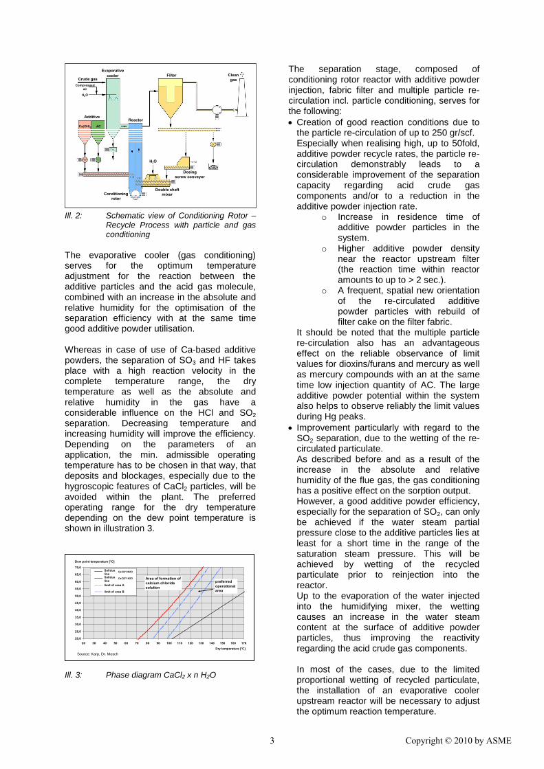
The evaporative cooler (gas conditioning) serves for the optimum temperature adjustment for the reaction between the additive particles and the acid gas molecule, combined with an increase in the absolute and relative humidity for the optimisation of the separation efficiency with at the same time good additive powder utilisation. Whereas in case of use of Ca-based additive powders, the separation of SO3 and HF takes place with a high reaction velocity in the complete temperature range, the dry temperature as well as the absolute and relative humidity in the gas have a considerable influence on the HCl and SO2 separation. Decreasing temperature and increasing humidity will improve the efficiency. Depending on the parameters of an application, the min. admissible operating temperature has to be chosen in that way, that deposits and blockages, especially due to the hygroscopic features of CaCl2 particles, will be avoided within the plant. The preferred operating range for the dry temperature depending on the dew point temperature is shown in illustration 3. Ill. 3: Phase diagram CaCl2 x n H2O
The separation stage, composed of conditioning rotor reactor with additive powder injection, fabric filter and multiple particle re-circulation incl. particle conditioning, serves for the following: Creation of good reaction conditions due to
the particle re-circulation of up to 250 gr/scf. Especially when realising high, up to 50fold, additive powder recycle rates, the particle re- circulation demonstrably leads to a considerable improvement of the separation capacity regarding acid crude gas components and/or to a reduction in the additive powder injection rate.
o Increase in residence time of additive powder particles in the system.
o Higher additive powder density near the reactor upstream filter (the reaction time within reactor amounts to up to > 2 sec.).
o A frequent, spatial new orientation of the re-circulated additive powder particles with rebuild of filter cake on the filter fabric.
It should be noted that the multiple particle re-circulation also has an advantageous effect on the reliable observance of limit values for dioxins/furans and mercury as well as mercury compounds with an at the same time low injection quantity of AC. The large additive powder potential within the system also helps to observe reliably the limit values during Hg peaks.
Improvement particularly with regard to the SO2 separation, due to the wetting of the re-circulated particulate. As described before and as a result of the increase in the absolute and relative humidity of the flue gas, the gas conditioning has a positive effect on the sorption output. However, a good additive powder efficiency, especially for the separation of SO2, can only be achieved if the water steam partial pressure close to the additive particles lies at least for a short time in the range of the saturation steam pressure. This will be achieved by wetting of the recycled particulate prior to reinjection into the reactor. Up to the evaporation of the water injected into the humidifying mixer, the wetting causes an increase in the water steam content at the surface of additive powder particles, thus improving the reactivity regarding the acid crude gas components.
In most of the cases, due to the limited proportional wetting of recycled particulate, the installation of an evaporative cooler upstream reactor will be necessary to adjust the optimum reaction temperature.
Evaporativecooler Filter Clean
gas
Dosingscrew conveyor
Double shaftmixer
H2O
Conditioningrotor
Reactor
Crude gasCompressed
air
H2O
Additive
Ca(OH)2 AC
20,0
25,0
30,0
35,0
40,0
45,0
50,0
55,0
60,0
65,0
70,0
20 30 40 50 60 70 80 90 100 110 120 130 140 150 160 170
Soliduslinie CaCl2*2H2O
Soliduslinie CaCl2*1H2O
Bereichsgrenze A
Bereichsgrenze B
Dry temperature [°C]
Dew point temperature [°C]
Area of formation ofcalcium chloridesolution
preferredoperationalarea
Source: Karp, Dr. Mosch
SoliduslineSoliduslinelimit of area A
limit of area B
3 Copyright © 2010 by ASME

2.2 Conditioning rotor Due to the requested, necessary high particle recycle rates and in order to grant an optimum additive powder efficiency, it will be necessary to use re-circulation systems which can reliably handle considerable recycling quantities, even if larger quantities of difficult particles, such as CaCl2, are present in the particle spectrum. The Conditioning Rotor – Recycle Process offers a technology which has been applied successfully for many years for various fields of application. The transport of particles from the filter to the reactor takes place mechanically. Conveying with pneumatic methods, which is prone to frequent breakdowns, is not used. The conditioning rotor is located in the lower reaction chamber elbow of the two-pass reactor (ill. 4). The rotor is a hollow cylinder, made of a perforated plate with openings of approx. 1 x 1 inch. Up to 10% of its volume is filled with balls made of heat-and wear-resistant ceramics. The rotor is supported on both sides, outside of the adjacent walls, and is continuously rotating with approx. 1 rpm by means of a geared motor. The rotation causes the balls to move relatively to each other inside of cylinder and to the perforated shell. Ill. 4: Conditioning rotor The objectives of a conditioning rotor are: - Avoidance of particle deposits when
reversing a particle-laden gas flow - Achievement of a homogeneous
distribution of new additive powder injected into the gas flow in reactor
- Disintegration of larger agglomerates with a descent velocity higher than the transport velocity in the ascending part of reactor
The wetted re-circulated particles cannot be injected in the gas flow upstream conditioning rotor but descending agglomerates will be disintegrated to such an extent that they can be carried along with the gas flow towards the
filter. A discharge system underneath the reaction chamber elbow will not be necessary. 2.3 Application examples Representing many realised plants with Conditioning Rotor - Recycle Process and particle conditioning, illustration 5 shows the gas cleaning system of line no. 2 of the WtE plant in the city of Ludwigshafen/Germany. Furthermore, in addition to the photo of plant, a table shows the crude gas values downstream boiler. The emission limit values to be observed correspond, for most of the gas substances, to the requirements of the EU directive. Furthermore, regarding SO2, a limit value of 9 ppm and for Hg a limit value of 15µg/Nm³ has to be observed. Ill. 5: WtE plant Ludwigshafen / Germany Illustration 6 shows the trend curves of crude gas and clean gas values for HCl and SO2 over a period of 24 hours as well as the stoichiometric factor for the Ca(OH)2 injection. Ill. 6: Trend curves crude gas / clean gas values
and stoichiometry In case of an average HCl crude gas value of approx. 2,000 mg/Nm³ (1,250 ppm), clean gas values of approx. 5 mg/Nm³ (3 ppm) will be achieved. The SO2 crude gas values of in average approx. 450 mg/Nm³ (160 ppm) will be
Filter
ReactorAdditive
Conditioning rotorfor reaction chamber
Conditioning rotorfor reaction chamberCrude
gas
Volume flow : 60,000 scfm
Overall dust [gr/scf]HCl [ppm]HF [ppm]SO2 [ppm]Hg [g/Nm³ dry]Cd + TI [mg/Nm³ dry] Heavy metal [mg/Nm³ dry]Dioxin / Furan [ngTE/Nm³ dry]
0.64 2620 1,24017 34150 225300 3001.0 3.020 503.0 5.0
DAV HAV
0.004 0.0086 361 49 4515 300.05 *0.5 *0.1 *
Boiler outlet Emission limitvalues
* Average value over sample taking period
DAV HAV
HC
l-, S
O2-C
rude
gas
, SO
2-Cle
an g
as [m
g/N
m³d
ry]
4000
SO2 downstream boiler
HCl downstream boiler
SO2 stack
-5000
-4000
-3000
-2000
-1000
0
2000
3000
5000
0
2
8
10
12
14
16
18
00:00 00:0004:00 08:00 12:00 16:00 20:00
HC
l-Cle
an g
as, S
toic
hiom
etry
HCl stack
Stoichiometry
4
6
1000
4 Copyright © 2010 by ASME

separated to approx. 100%. The stoichiometry totals to a factor of approx. 2. Table 2 shows the results of a dioxin measurement. The specific injection quantity of AC totals to approx. 0.03 gr/scf. Even the requested emission limit values for Hg will reliably be kept in continuous operation with this injection quantity. Tab. 2: Results of dioxin/furan measurement WtE
plant Ludwigshafen The supervision of the emission limit value for Hg as well as for HCl, SO2 and dust, takes place by means of continuous measuring instruments in the stack. The conditioned dry gas cleaning system installed in 2004, replaced a definitely more complex, wet system, consisting of spray dryer, ESP, multi-stage scrubber and aerosol separator (illustration 7). Ill. 7: Upgrading of WtE plant Ludwigshafen from
„wet“ to „conditioned dry“
Up to the year 2008, another wet flue gas treatment system had been operated in parallel at the waste incinerator in Ludwigshafen until its upgrading, thus allowing a direct comparison between both installed systems. Illustration 8 shows the average values for selected gas substances of the year 2005. The comparison shows that the Conditioning Rotor – Recycle Process with particle conditioning is equal to the more complex wet system. Differences are only displayed for HCl and SO2. With regard to the wet system, HCl is nearly completely separated in the acid stage of the scrubber. The injection of NaOH as additive in the basic stage takes place subject to the SO2 clean gas value (ph-value control). In case of the conditioned dry sorption, HCl is the reference variable for the additive powder injection as far as the ratio HCl ./. SO2 is > 2,5. The injection rate depends on the HCl emission limit value. Ill. 8: Comparison of gas cleaning systems „wet“
and „conditioned dry“ (2005) 3. Conditioning Rotor – Recycle Process
with graded additive powder injection As a result of the ban on landfill of higher caloric substances in Germany in the year 2005, incinerators for RDF (Refuse Derived Fuel) have been installed for many applications beside the conventional waste incinerators. Compared to the untreated waste, the used fuels are often containing definitely higher Cl- and S-concentrations. The crude gas values measured at realised plants downstream boiler, often total to > 1,600 ppm for HCl and > 650 ppm for SO2 in continuous operation. With regard to these high crude gas values and when using the technology described in section 2 of this lecture without any additional measures, the stoichiometry has to be increased partly definitely above a typical base value of 2 in order to reliably meet the
0
5
10
15
20
25
30
35
40
45
50
HCl SO2 Hg Staub C ges. NH3 NO2
Rohgaswerte:
HCl 1335 mg/ Nm³SO2 303 mg/Nm³NOX 290 mg/Nm³Feuchte 13 Vol %
Con
cent
ratio
n
Crude gas component
Dust C total
Crude gas values :HCl 1,335 mg/Nm³ / 820 ppmSO2 303 mg/Nm³ / 106 ppmNOX 290 mg/Nm³ / 140 ppmHumidity 13 %Vol.
FGT 2 dryFGT 3 wet
NH3 NO2HgSO2HCl
10
0
50
40
30
20
Spray dryer
ESP Scrubber Scrubber 3 WetESP
SCR-DENOX
RemainderLime slurry
NaOH
Ammoniawater
Naturalgas
DENOX-CatOxi-Cat
Stack
Source: TWL
NaOHActivated carbon
Dosingscrew conveyor
Cleangas
Filter
H2O
Evaporativecooler
Double shaftmixer
Crude gasCompressedair
H2O
Summery of measuring results
The table below shows a summary of measuring results.The concentrations are referred to the standard conditions (1.013 hPa,273 K) and dry exhaust gas.
In the following table the concentrations are referred to standardconditions (1.013 hPa, 273 K), dry exhaust gas and addition to anoxygen content of 11 %Vol.
Measurement 1 2 3Dust [mg/m³] 1.4 < 1.0 < 1.3PCDD/PCDF [ng/m³] < 0.001 < 0.001 < 0.001I-Teq. accord. toannex 17 BImSchV
Measurement 1 2 3Dust [mg/m³] 1.1 < 0.9 < 1.1PCDD/PCDF [ng/m³] < 0.001 < 0.001 < 0.001I-Teq. accord. toannex 17 BImSchV
Source: ANECO / 04 8077/3 E
5 Copyright © 2010 by ASME

emission limit values. Regarding these types of applications it will be advisable to use a graded additive powder injection, thus using in addition the reaction chamber of evaporative cooler when indicated. Illustration 9 shows different, corresponding process variants. For all concepts, the main quantity of additive powder is in the nominal case injected into the reactor downstream evaporative cooler. The injection of additive powder upstream or inside of evaporative cooler mainly serves for the corrosion protection as well as for the smoothening of crude gas peaks. Ill. 9: Conditioning Rotor – Recycle Process with
graded additive powder injection All process variants have already been realised. The preferred system is the graded injection of Ca(OH)2 upstream and downstream of evaporative cooler, among other things due to the improved economics. 3.1 Application example Illustration 10 shows the RDF incineration at Stavenhagen/Germany as representative for several realised plants, executed as Conditioning Rotor – Recycle Process with graded additive powder injection. The table in this illustration specifies the gas substances downstream boiler relevant for the gas cleaning. Especially noticeable is the max. daily average value for SO2, totalling to up to 700 ppm. Half-hour average values or peaks can, of course, be definitely higher. The requested emission limit values according to EU directive can reliably be kept in continuous operation.
Ill. 10: RDF incineration plant Stavenhagen /
Germany ● Acid crude gas components The injection quantity of Ca(OH)2 is controlled subject to a given stoichiometric factor (ill. 11). The necessary additive powder mass flow is calculated according to the adjusted stoichiometric factor and on the basis of the volume flow and the HCl and SO2 values, which are continuously measured in the crude gas upstream evaporative cooler. In addition to this and in case of increased crude gas values, the stoichiometric factor is automatically increased by means of a superposed adjustment curve. Furthermore, the monitoring of the emission values, combined with the increase in the injection quantity in case of reaching the clean gas limit values for HCl and SO2, ensures that the emission values (DAV and HAV) will by no means be exceeded. Ill. 11: Control scheme Ca(OH)2 injection
Filter Cleangas
Dosingscrew conveyor
Double shaftmixer
H2O
Conditioningrotor
Reactor
Crude gas
Compressed air
H2O
Additive
Ca(OH)2 AC
NaHCO3
Ca(OH)2 Lime slurry
NaOH
DAV
nominal
DAV
maximal Particles gr/scf 0.4 1
HCL ppm 800 1,600
HF ppm 25 50
SO2 ppm 385 700
Hg g/Nm³ 120 120
Heavy metals mg/Nm³ dry 27.5 * 100 *
Cd / TI mg/Nm³ dry 1.3 * 6.0 *
PCDD / PCDF ng/Nm³ dry 3.0 * 4.0 *
* Average value over sample taking period
Volume flow : 62,000 scfm
HClCrude gas
Volumeflow
SOXCrude gas
HClMass flow
SO2Mass flow
Ca(OH)2Mass flow
i = 1
1.01 1.16
Stoichiometryfactor
Ca(OH)2Mass flow
Correctionfactor cleangas values
Correctionfactor crudegas values
Base valuee.g. 2
X X
X
6 Copyright © 2010 by ASME

The graded additive powder injection allows to achieve and/or to undercut the intended stoichiometric factor of 2 with reliable observance of emission limit values. The averaged stoichiometric factor actually reached in continuous operation has repeatedly been determined by means of remainder analyses. It lies in a range between 1.8 up to 2.0. Table 3 exemplary shows the corresponding analysis of a material sample taken in October 2007. The stoichiometric factor is in this case < 1.9. The Cl content totals to approx. 20 weight%, thus lying in a range, noncritical for the product handling. Tab. 3: Calculation of stoichiometry based on
remainder analysis ● Dioxins/Furans and Hg as well as Hg compounds Activated carbon with a standard dosing quantity is used as additive powder for the separation of mercury and/or mercury compounds and dioxins/furans. The continuously measured Hg clean gas values are definitely < 5 µg/Nm³ dry. Measuring results for PCPP/-F are listed in table 4. Tab. 4: Results of dioxin/furan measurements at
WtE plant Stavenhagen 4. Utilisation of CaO instead of Ca(OH)2
for the reduction of operating costs In case of the conditioned dry sorption, the Ca-based additive powder is injected into the reactor dry in form of Ca(OH)2. Compared to the use of CaO as e.g. for the spray sorption, this presents a disadvantage due to the higher purchase costs for Ca(OH)2. In order to
compensate this cost disadvantage, plants with a higher additive powder consumption are often provided in addition with a dry hydrator for CaO. In this case, the additive powder is supplied in form of CaO. It is converted to Ca(OH)2 by means of H2O injection in a dry hydrator and is stored in an intermediate silo or the injection into the reactor and/or also upstream evaporative cooler as dry additive powder. The intermediate silo is adequately dimensioned to allow a direct filling of silo with Ca(OH)2 in case of maintenance and repair works near the dry hydrator. A corresponding scheme is shown in illustration 12. Ill. 12: Rough scheme dry hydration CaO Several plants in Germany have been provided with this technology. Illustration 13 shows a plant, realised with a dry hydrator for a Ca(OH)2 production capacity of approx. 3.5 tn/h (ill. 14). Ill. 13: RDF incineration plant EEW Premnitz/
Germany As alternative there is the possibility to install the dry hydrator close to the additive powder injection point near the reactor. The produced Ca(OH)2 can now be injected directly into the reactor without temporary storage in a silo. This variant will not be possible in case of a graded additive powder injection.
n Maximum Extended Limit Condition[mg/m³] measuring value of highest
uncertainty emission
PCCD/PCDF 1 0.0015 ng/m³ 0.0002 ng/m³ 0.1 ng/m³ yes
Benzopyrene 3 < 0.0022 0.0002 0.009 yes
Analysis Value [%] Ca Ca(OH)2 Residual lime,content content calculated as
in substance in substance Ca(OH)2
Ca 29.8CaSO3 5.25 1.8 3.2CaSO4 7.92 2.3 4.2CaCO3 8.07 3.2 6.0CaCl2 31.4 11.4 21.1CaF2 0.23 0.1 0.2Ca(OH)2 18.0 9.7 18.0Sum 28.7 24.0
Ca(OH)2 input : 28.7 + 24.0 = 52.7
converted Ca(OH)2 : 28.7
Stoichiometry i : i = 52.7 28.7 = 1.83
7 Copyright © 2010 by ASME
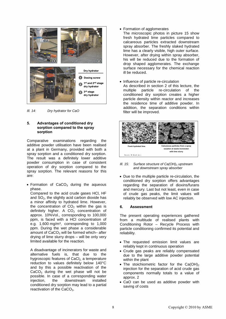
Ill. 14: Dry hydrator for CaO 5. Advantages of conditioned dry
sorption compared to the spray sorption
Comparative examinations regarding the additive powder utilisation have been realised at a plant in Germany, provided with both a spray sorption and a conditioned dry sorption. The result was a definitely lower additive powder consumption in case of consistent operation of dry sorption compared to the spray sorption. The relevant reasons for this are: Formation of CaCO3 during the aqueous
phase. Compared to the acid crude gases HCl, HF and SO2, the slightly acid carbon dioxide has a minor affinity to hydrated lime. However, the concentration of CO2 within the gas is definitely higher. A CO2 concentration of approx. 10%Vol., corresponding to 100,000 ppm, is faced with a HCl concentration of e.g. 1,600 mg/m³, corresponding to 1,000 ppm. During the wet phase a considerable amount of CaCO3 will be formed which– after drying of lime slurry drops – will be only very limited available for the reaction.
A disadvantage of incinerators for waste and alternative fuels is, that due to the hygroscopic features of CaCl2, a temperature reduction to values definitely below 140°C and by this a possible reactivation of the CaCO3 during the wet phase will not be possible. In case of a corresponding water injection, the downstream installed conditioned dry sorption may lead to a partial reactivation of the CaCO3.
Formation of agglomerates The microscopic photos in picture 15 show fresh hydrated lime particles compared to calcareous particles extracted downstream spray absorber. The freshly slaked hydrated lime has a clearly visible, high outer surface. However, after drying within spray absorber, his will be reduced due to the formation of drop shaped agglomerates. The exchange surface necessary for the chemical reaction ill be reduced.
Influence of particle re-circulation
As described in section 2 of this lecture, the multiple particle re-circulation of the conditioned dry sorption creates a higher particle density within reactor and increases the residence time of additive powder. In addition, the separation conditions within filter will be improved.
Ill. 15: Surface structure of Ca(OH)2, upstream
and downstream spray absorber Due to the multiple particle re-circulation, the
conditioned dry sorption offers advantages regarding the separation of dioxins/furans and mercury. Last but not least, even in case of crude gas peaks, the limit values will reliably be observed with low AC injection.
6. Assessment The present operating experiences gathered from a multitude of realised plants with Conditioning Rotor – Recycle Process with particle conditioning confirmed its potential and reliability. The requested emission limit values are
reliably kept in continuous operation Crude gas peaks are reliably compensated
due to the large additive powder potential within the plant
The stoichiometric factor for the Ca(OH)2 injection for the separation of acid crude gas components normally totals to a value of approx. 2
CaO can be used as additive powder with saving of costs
11 22
33
Dry hydratorDry hydrator
Dosing screwDosing screw
11stst andand 22ndnd stagestagedry hydratordry hydrator
33rdrd stagestagedry hydratordry hydrator
11
22
33
Source : R. Karpf, ete.a
Fresh hydrated lime Calcareous particles from a spray sorption at waste incinerator
with lime slurry
8 Copyright © 2010 by ASME

The injection quantity for AC totals to a specific value of approx. 0.03 gr/scf
The comparatively simple structure grants a high availability
Higher requirements on the separation of acid crude gas e.g. due to high crude gas values, can be compensated in a simple way by means of the graded additive powder injection
A comparison of emission limit values for waste incinerators in the USA and Europe shows, that the presented technology will also be suited for the use on the American market and can offer cost advantages for the operators of waste incinerators.
9 Copyright © 2010 by ASME