Embed Size (px)
Citation preview
STRUCTURES
SECTION 400 CONCRETE STRUCTURES
400-1 Description. Construct concrete structures and other concrete members, with the exception of pavement and incidental concrete construction (which are specified in other Sections). Refer to Section 450 for prestressed construction requirements additional to the requirements of this Section. For precast concrete structures meet the requirements of Section 450 for inserts and lifting devices, handling, storage, shipping, and erection. Obtain incidental precast products from a plant that is currently on the Department’s Production Facility Listing. Producers seeking inclusion on the list shall meet the requirements of Section 105.
400-2 Materials. Meet the following requirements:
Concrete .............................................. Sections 346 and 347 Penetrant Sealer ................................................. Section 413 High Molecular Weight Methacrylate (HMWM)** ........................................................................... Section 413 Reinforcing Steel ............................................... Section 415 Water .................................................................. Section 923 Curing Materials* .............................................. Section 925 Epoxy Bonding Compounds** ........... Sections 926 and 937 Joint Materials** ................................................ Section 932 Bearing Pads ...................................................... Section 932 Non-Shrink Grout** .......................................... Section 934 Class 5 Applied Finish Coatings** .................... Section 975 Galvanizing Compound** ................................. Section 562 Dowel Bar Assembly** ..................................... Section 931 Filter Fabric ........................................................ Section 985 *The Engineer will allow clean sand and sawdust for certain curing, when and as specified. **Use products listed on the Department’s Approved Product List (APL).
400-3 Depth of Footing. Refer to Section 455, “D. SPREAD FOOTINGS”.
400-4 Falsework. 400-4.1 Plans: At the Engineer’s request, furnish detailed plans for falsework or centering to the Department. The Contractor is responsible for results obtained by using these plans. 400-4.2 Design and Erection: Design and construct all falsework to provide the necessary rigidity and to support the loads without appreciable settlement or deformation. Use
screw jacks or hardwood wedges to take up any settlement in the framework, either before or during the placing of concrete. If any weakness develops and the centering shows undue settlement or distortion, stop the work, remove any masonry affected, and strengthen the falsework before resuming work. Support falsework which cannot be founded on a satisfactory footing on piling. Space, drive, and remove the piling in an approved manner. 400-4.3 Camber: Provide camber to correct for settlement and deflection of falsework. Give bridges permanent camber only when shown in the Plans. 400-4.4 Bridge Deck Overhang Falsework for Steel I-Girders: Locate the lower contact point of bridge deck overhang falsework supporting screed rails within 6 inches above the bottom flange. If the lower contact point of the overhang falsework bears more than 6 inches above the bottom flange and/or if the deck overhang is 4 feet or greater, submit shop drawings and calculations to the Engineer in accordance with Section 5 and Chapter 11 of the Structures Design Guidelines (SDG). The deck overhang is measured from the centerline of the girder supporting the overhang falsework to the outside edge of the concrete deck.
400-5 Forms. 400-5.1 General: Provide forms, either of wood or metal, that are as follows: externally secured and braced where feasible; substantial and unyielding; of adequate strength to contain the concrete without bulging between supports and without apparent deviation from the neat lines, contours, and shapes shown in the Plans. Design forms to withstand the additional forces of vibration without apparent deviation from the desired shape or position. Assemble forms to be mortar-tight. If using lumber forms, construct them of dressed wood of uniform thickness. Use form liners on wooden forms where Class 3 surface finish is specified. Construct assembled forms to render a concrete surface of smooth, uniform finish. Make provisions to remove forms without injury to concrete surfaces. Remove blocks and bracing with the forms, and do not leave any portion of the forms in the concrete. Use the same form system for a type of work throughout. 400-5.2 Inspection and Approval: Do not place concrete in a form until the form has been inspected and approved. Although the Engineer inspects and approves the forms, the Contractor is responsible for obtaining satisfactory concrete surfaces, free from warping, bulging, or other objectionable defects. Pay special attention to the ties and bracing. Where the forms appear to be insufficiently braced or unsatisfactorily built, stop and correct defects to the satisfaction of the Engineer. 400-5.3 Non-metallic Form Materials: 400-5.3.1 Lumber: For all surfaces, use lumber that is not less than 3/4 inch in thickness, dressed, and free of knot holes, loose knots, cracks, splits, warps, and other defects. Proportion the spacing of studs, joists, and wales to exclude warps and bulges and to produce true and accurate concrete surfaces. Only use structurally sound lumber. 400-5.3.2 Form Liners: Use form liners of durable, abrasion resistant materials that are unaffected by water. Use liners with a hard surface texture capable of rendering concrete surfaces of a smooth, uniform texture, without grain marks, patterns, or blemishes. Use form liner material of sufficient thickness to eliminate the reflection of irregularities, undesirable patterns, and marks from the forms to the surfaces. Replace liners as necessary to produce a consistent concrete surface texture. Use form liners in large sheets and with true, tight-fitted joints which are logically located. Obtain the Engineer’s approval of the layout of sheets. Do not use liners which have been patched. Use liner material of the same stock throughout.

400-5.3.3 Plywood: The Contractor may use plywood of not less than 5/8 inch in thickness manufactured with waterproof glue or protected with an approved impervious coating. Do not use pieces with bulged plies or raveled, untrue edges. 400-5.4 Special Requirements: 400-5.4.1 Re-entrant Angles: Use chamfered forms for exterior concrete corners and filleted forms for interior concrete corners. Use chamfers and fillets that are 3/4 by 3/4 inch and are mill-dressed on all sides to uniform dimensions. The Contractor may use plastic or metal chamfers and fillets provided they perform satisfactorily in producing uniform, smooth concrete corner surfaces without honeycomb. 400-5.4.2 Handrails and Parapets: Construct barriers and parapets in accordance with Section 521. 400-5.4.3 End-bent Caps: Do not place forms for end-bent caps until the embankment has been constructed to within 12 inches of the bottom of the cap. Place a mass of embankment that is sufficient to produce the subsidence, displacement, and settlement which may result from the construction of the total embankment. 400-5.4.4 Footings: Where footing concrete can be placed in dry excavation, the Contractor may omit cribs, cofferdams, and forms, subject to compliance with the following limitations and conditions: 1. Use this procedure only in locations not exposed to view from traveled roadways. 2. Obtain required elevations shown in the Plans. 3. Obtain neat line dimensions shown in the Plans. 4. Fill the entire excavation with concrete to the required elevation of the top of the footing. 5. The Engineer will determine the volume of footing concrete to be paid for from the neat line dimensions shown in the Plans. 400-5.5 Form Alignment, Bracing, and Ties: Construct forms in such manner that they may be adequately secured for alignment, shape, and grade. Use bracing systems, ties, and anchorages that are substantial and sufficient to ensure against apparent deviation from shape, alignment, and grade. Do not drive nails into existing concrete. Do not use bracing systems, ties, and anchorages which unnecessarily deface or mark, or have an injurious or undesirable effect on surfaces that will be a part of the finished surface. If metal ties and anchorages are to remain in the concrete, construct them so as to permit the removal of metal to at least 1 inch beneath the finished surface of concrete. Use accessories for metal ties and anchorages that allow the removal of metal to the prescribed depth while leaving the smallest possible repairable cavity. When using wire ties, cut or bend them back from the finished surface of the concrete a minimum of 1 inch. Do not use internal ties of wire when forming surfaces that are exposed to view. 400-5.6 Preparation and Cleaning: Meet the following requirements for the condition of forms at the time of beginning concrete casting: 1. Treat all forms with an approved form-release agent before placing concrete. Do not use material which adheres to or discolors the concrete. 2. Clean forms of all concrete laitance from previous use and all dirt, sawdust, shavings, loose wire ties and other debris. 3. Close and secure all inspection and cleanout holes.
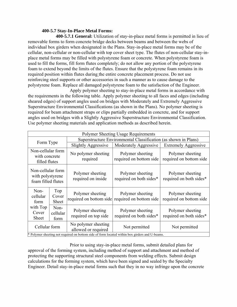
400-5.7 Stay-In-Place Metal Forms: 400-5.7.1 General: Utilization of stay-in-place metal forms is permitted in lieu of removable forms to form concrete bridge decks between beams and between the webs of individual box girders when designated in the Plans. Stay-in-place metal forms may be of the cellular, non-cellular or non-cellular with top cover sheet type. The flutes of non-cellular stay-in-place metal forms may be filled with polystyrene foam or concrete. When polystyrene foam is used to fill the forms, fill form flutes completely; do not allow any portion of the polystyrene foam to extend beyond the limits of the flutes. Ensure that the polystyrene foam remains in its required position within flutes during the entire concrete placement process. Do not use reinforcing steel supports or other accessories in such a manner as to cause damage to the polystyrene foam. Replace all damaged polystyrene foam to the satisfaction of the Engineer. Apply polymer sheeting to stay-in-place metal forms in accordance with the requirements in the following table. Apply polymer sheeting to all faces and edges (including sheared edges) of support angles used on bridges with Moderately and Extremely Aggressive Superstructure Environmental Classifications (as shown in the Plans). No polymer sheeting is required for beam attachment straps or clips partially embedded in concrete, and for support angles used on bridges with a Slightly Aggressive Superstructure Environmental Classification. Use polymer sheeting materials and application methods as described herein.
Polymer Sheeting Usage Requirements
Form Type Superstructure Environmental Classification (as shown in Plans)
Slightly Aggressive Moderately Aggressive Extremely Aggressive Non-cellular form
with concrete filled flutes
No polymer sheeting required
Polymer sheeting required on bottom side
Polymer sheeting required on bottom side
Non-cellular form with polystyrene foam filled flutes
Polymer sheeting required on inside
Polymer sheeting required on both sides*
Polymer sheeting required on both sides*
Non-cellular
form with Top
Cover Sheet
Top Cover Sheet
Polymer sheeting required on bottom side
Polymer sheeting required on bottom side
Polymer sheeting required on bottom side
Non-cellular
form
Polymer sheeting required on top side
Polymer sheeting required on both sides*
Polymer sheeting required on both sides*
Cellular form No polymer sheeting allowed or required
Not permitted Not permitted
* Polymer sheeting not required on bottom side of form located within box girders and U-beams.
Prior to using stay-in-place metal forms, submit detailed plans for approval of the forming system, including method of support and attachment and method of protecting the supporting structural steel components from welding effects. Submit design calculations for the forming system, which have been signed and sealed by the Specialty Engineer. Detail stay-in-place metal forms such that they in no way infringe upon the concrete
outline of the slab shown on the Plans. Use stay-in-place metal forms that provide and maintain the dimensions and configuration of the original slab in regards to thickness and slope. Do not weld stay-in-place metal form supports and connections to the structural steel components. Do not connect polymer coated angles or other hardware that support polymer coated metal forms to the beam attachment straps or clips by welding. Electrical grounding to reinforcing steel is prohibited. Protect structural steel components from damage by using a shield to guard against weld splatter, weld overrun, arc strikes, or other damaging effects of the welding process. Upon completion of welding, rest the metal form support flush on the supporting steel component. Should any weld spatter, weld overrun, arc strike, or other effects of the welding process be evident or occur to the structural steel component, immediately stop in-place welding of the metal form supports for the remainder of the work. In this event, weld all metal form supports off of the structure and erect the forms after prefabrication, or use an alternate approved method of attaching the form supports. Remove improper weldment, repair the supporting steel component for any improper welding. Perform all required verification and testing at no expense to the Department and to the satisfaction of the Engineer. Do not use stay-in-place metal forms until the forming system has been approved by the Engineer. The Contractor is responsible for the performance of the stay-in-place forms. Structures designed, detailed, and dimensioned for the use of removable forms: Where stay-in-place metal forms are permitted, the Contractor is responsible and shall obtain the approval of the Engineer for any changes in design, etc. to accommodate the use of stay-in-place forms. The Engineer will compute pay quantities of the various components of the structure which are paid on a cubic yard basis from the design dimensions shown in the Plans with no allowance for changes in deflection or dimensions necessary to accommodate the stay-in-place forms or concrete to fill the form flutes. The Engineer will limit pay quantities of other Contract items that the Contractor increases to accommodate the use of stay-in-place forms to the quantity required for the original plan design. Submit all changes in design details of bridge structural members that support stay-in-place forms, showing all revisions necessary to enable the supporting components to withstand any additional weight of the forms and the weight of any extra concrete that may be required to fill the forms. Include with the design calculations a comparative analysis of the stresses in the supporting components as detailed on the Contract Plans and as modified to support the forms. Use the identical method of analysis in each case, and do not allow the stresses in the modified components to exceed those of the component as detailed in the Contract Plans. Include with the design the adjusted cambers for any changes in deflection over those shown on the original Plans. Modify the beams to provide additional strength to compensate for the added dead loads imposed by the use of stay-in-place forms. Obtain the additional strength by adding strands to the pre-stressed beams or by adding steel material to increase the section modulus of steel girders. Substantiate the added strength by the comparative calculations. Do not use stay-in-place forms until the forming system and all necessary design revisions of supporting members have been approved by the Engineer. Structures designed, detailed, and dimensioned for the use of stay-in-place metal forms: Prior to using stay-in-place metal forms, submit detailed plans for approval of the forming system (including method of support and attachment) together with
design calculations. Include an analysis of the actual unit weight of the proposed forming system over the projected plan area of the metal forms. If the weight thus calculated exceeds the weight allowance for stay-in-place metal forms and concrete required to fill the forms shown on the Plans, then modify the supporting components to support the excess weight as specified by the Contractor’s Specialty Engineer. For all structures utilizing structural steel supporting components, paint the vertical sides of the top flange prior to installation of the stay-in-place metal forms in accordance with Section 560. For non-polymer sheeting form surfaces, use zinc paint coating in accordance with Section 562 to all accessories cut from galvanized sheets, which are not embedded in concrete. 400-5.7.2 Design: Meet the following criteria for the design of stay-in-place bridge deck forms: 1. The maximum self weight of the stay in place metal forms, plus the weight of the concrete or expanded polystyrene required to fill the form flutes (where used), shall not exceed 20 psf. 2. Design the forms on the basis of dead load of form, reinforcement, and plastic concrete plus 50 pounds per square foot for construction loads. Use a unit working stress in the steel sheet of not more than 0.725 of the specified minimum yield strength of the material furnished, but not to exceed 36,000 psi. 3. Do not allow deflection under the weight of the forms, reinforcement, and plastic concrete to exceed 1/180 of the form span or 1/2 inch, whichever is less, for form spans of 10 feet or less, or 1/240 of the form span or 3/4 inch, whichever is less, for form spans greater than 10 feet. In all cases, do not use a total loading (psf) that is less than 20 plus the product of the deck thickness measured in inches times 12.5. 4. Use a design span of the form equal to the clear span of the form plus 2 inches. Measure the span parallel to the form flutes. 5. Compute physical design properties in accordance with requirements of the AISI Specifications for the Design of Cold Formed Steel Structural Members, latest published edition. 6. For all reinforcement, maintain the design concrete cover required by the Plans. 7. Maintain the plan dimensions of both layers of primary deck reinforcement from the top surface of the concrete deck. 8. Do not consider the permanent bridge deck form as lateral bracing for compression flanges of supporting structural members. 9. Do not use permanent steel bridge deck forms in panels where longitudinal deck construction joints are located between stringers. 10. Secure forms to the supporting members by means other than welding directly to the member. 400-5.7.3 Materials: 400-5.7.3.1 Metal Forms: Fabricate stay-in-place metal forms and supports from steel meeting the requirements of ASTM A653 having a coating designation G165. Do not use form materials that are less than 0.03 inch uncoated thickness. 400-5.7.3.2 Polymer Sheeting: Use polymer sheeting comprised of at least 85% ethylene acrylic acid copolymer capable of being applied to both G165 and G210 steel

sheet as described in ASTM A742. Ensure that the polymer sheeting has a nominal thickness of 12 mils as manufactured and a minimum thickness of 10 mils after lamination to the steel sheet. Ensure that the polymer sheeting remains free of holes, tears and discontinuities and sufficiently flexible to withstand the forming process without any detrimental effects to bond, durability or performance. Ensure that the polymer sheeting is UV stabilized and contains antioxidants. Ensure that the as-manufactured polymer sheeting (prior to application) has an Oxidative Induction Time (OIT) of 60 to 75 minutes at 170°C in air when tested according to ASTM D3895. Perform additional OIT tests on samples taken from the finished product (polymer sheeting applied to forms) resulting in a minimum OIT according to ASTM D3895 of 32 minutes at 170°C in air. Ensure that the polymer sheeting adheres to galvanized metal sufficient to prevent undercutting at penetrations made through the polymer sheeting or metal forms to the satisfaction of the Engineer. Ensure that edges subjected to shear cutting are coated by the form manufacturer with two coats of a compatible liquid coating repair material before delivery to the site. Ensure that steel used to produce polymer laminated metal forms is appropriately cleaned and prepared per NCCA (National Coil Coating Association) standard continuous coil coating practices. Ensure that pretreatment for use in conjunction with the manufacturer’s polymer sheeting material is approved as compatible by the polymer sheeting manufacturer. Apply pretreatment in accordance with the polymer sheeting manufacturer’s procedures. Apply polymer sheeting in accordance with the manufacturer’s recommendations and procedures. Ensure that all steel has the polymer sheeting applied prior to fabrication of the stay-in-place forms and accessories. Ensure that the screws to be used in the fastening of the stay-in-place laminated metal forms have a corrosion resistant cladding that will not have an adverse effect to the system due to the contact of dissimilar metals. 400-5.7.3.3 Certification: Provide a written certification from the manufacturer stating the product meets the requirements of this specification along with the delivery of the coated forms to the jobsite. Ensure that the certification conforms to the requirements of Section 6. Ensure that the manufacturer has a quality control program conforming to ISO 9001 2000 standards. 400-5.7.3.4 Polystyrene Foam: Use polystyrene foam comprised of expanded polystyrene manufactured from virgin resin of sufficient density to support the weight of concrete without deformation. Extrude the polystyrene foam to match the geometry of the flutes and provide a snug fit. Use polystyrene foam that has a density of not less than 0.8 pounds per cubic foot. Use polystyrene foam that has water absorption of less than 2.6% when tested according to ASTM C272. Provide a written certification from the manufacturer stating the product meets the requirements of this Specification along with the delivery of the product. 400-5.7.4 Construction: Install all forms in accordance with approved fabrication and erection plans. Do not rest form sheets directly on the top of the stringer of floor beam flanges. Fasten sheets securely to form supports, and maintain a minimum bearing length of 1 inch at each end for metal forms. Place form supports in direct contact with the flange of the stringer or floor beam. Make all attachments for coated metal forms by bolts, clips, screws, or other approved means. 400-5.7.4.1 Form Galvanizing Repairs: For any permanent exposed steel where the galvanized coating has been damaged, thoroughly clean, wire brush, and paint it with
two coats of galvanizing compound in accordance with Section 562 to the satisfaction of the Engineer. Do not touch up minor heat discoloration in areas of welds. 400-5.7.4.2 Polymer Sheeting Repairs: Inspect and identify areas for damage to the polymer sheeting and repair with liquid polymer coating similar and compatible with respect to durability, adhesion and appearance in accordance with ASTM A762, as furnished by the stay-in-place form manufacturer. Ensure that the inspection includes checking the polymer sheeting for cuts, tears, cracking, surface pits, peeling, dirt, grease, oil, stains, rust or bare areas. Reject any panels that show coating blistering, peeling or cracking. Repair all polymer sheeting damage according to the following: 1. Surface Preparation: Ensure that all surfaces to be repaired are clean and free of any deleterious substances. Remove all traces of dirt, soil, oil deposits, greases, and other surface contaminates in accordance with the polymer sheeting and coating manufacturer’s written specifications prior to touch-up and recoating. 2. Application Procedures: Ensure that the liquid polymer repair coating is applied to a clean dry surface and in accordance with the manufacturer’s written specifications. Apply the repair coating using a suitable paintbrush or other means acceptable to the Engineer. Apply a first coat of product to the surface at 2-4 mils in thickness. Let the first coat air dry. Apply a second coat to form a complete layer and increase the thickness, immediately after verifying the first coat is dry to the touch (15 - 25 minutes depending on the local air drying temperature and atmospheric conditions). Apply the second coat at the same coating thickness as the first at 2-4 mils. Ensure that the total dry film thickness of the two coats is not less than 6 mils. Apply additional coats in this same manner until desired coating thickness is achieved. 400-5.7.5 Placing of Concrete: Vibrate concrete to avoid honeycomb and voids, especially at construction joints, expansion joints, valleys and ends of form sheets. Use approved pouring sequences. Do not use calcium chloride or any other admixture containing chloride salts in the concrete. 400-5.7.6 Inspection: The Engineer will observe the Contractor’s method of construction during all phases of the construction of the bridge deck slab, including the installation of the metal form system; location and fastening of the reinforcement; composition of concrete items; mixing procedures, concrete placement, and vibration; and finishing of the bridge deck. Should the Engineer determine that the procedures used during the placement of the concrete warrant inspection of the underside of the deck, remove at least one section of the metal forms in each span for this purpose. Do this as soon after placing the concrete as practicable in order to provide visual evidence that the concrete mix and the procedures are obtaining the desired results. Remove an additional section in any span if the Engineer determines that there has been any change in the concrete mix or in the procedures warranting additional inspection. If, in the Engineer’s judgment, inspection is needed to check for defects in the bottom of the deck or to verify soundness, sound the metal forms with a hammer as directed by the Engineer after the deck concrete has been in place a minimum of two days. If sounding discloses areas of doubtful soundness to the Engineer, remove the metal forms from such areas for visual inspection after the concrete has attained adequate strength. Remove metal bridge deck forms at no expense to the Department. At locations where sections of the metal forms have been removed, the Engineer will not require the Contractor to replace the metal forms. Repair the adjacent metal forms and supports to present a neat appearance and to ensure their satisfactory retention and
where they are polymer sheeted, coat all exposed surfaces of stay-in-place metal form system elements that are not coated or are damaged with a field applied liquid polymer coating as specified in 400-5.7.4.2. As soon as the form is removed, the Engineer will examine the concrete surfaces for cavities, honeycombing, and other defects. If irregularities are found, and the Engineer determines that these irregularities do not justify rejection of the work, repair the concrete as directed, and provide a General Surface Finish in accordance with 400-15. If the Engineer determines that the concrete where the form is removed is unsatisfactory, remove additional metal forms as necessary to inspect and repair the slab, and modify the method of construction as required to obtain satisfactory concrete in the slab. Remove and replace all unsatisfactory concrete as directed, at no expense to the Department. If the method of construction and the results of the inspections as outlined above indicate that sound concrete has been obtained throughout the slabs, the amount of sounding and form removal may be reduced when approved by the Engineer. Corrosion of assembly screws will not be considered a structural or aesthetic problem and is considered acceptable. Provide the facilities for the safe and convenient conduct of the inspection procedures. 400-5.8 Stay-In-Place Concrete Forms: 400-5.8.1 General: Permanent stay-in-place precast reinforced concrete forms may be used in lieu of removable forms to form concrete bridge deck slabs subject to the conditions contained herein. Precast reinforced concrete stay-in-place forms are not permitted to construct a composite concrete deck. Do not use precast prestressed concrete stay-in-place forms to form any permanent bridge decks. When detailed Plans for structures are dimensioned for the use of removable forms, provide additional slab thickness, elevation changes, changes in design, etc. to accommodate the use of stay-in-place forms, subject to the Engineer’s approval. The Engineer will compute pay quantities of the various component members of the structure which are paid on a cubic yard basis from the design dimensions shown in the Plans with no allowance for changes in deflection and changes in dimensions necessary to accommodate the stay-in-place forms. The Engineer will limit pay quantities of other Contract items which are increased to accommodate the use of stay-in-place forms to the quantity required for the original plan design. Prior to using stay-in-place forms, submit for approval detailed plans of the forming system and design calculations. Indicate on the plans the form panel sizes, placing patterns, type of mastic or felt bearing material and type and method of caulking between panels. Also, submit appropriate changes in design details of structural members supporting stay-in-place forms showing any revisions necessary to enable the supporting components to withstand the additional weight of the forms and perform equally as contemplated in the Plans. All calculations and details submitted shall be sealed by the Contractor’s Engineer of Record. Modify the beams to provide additional strength to compensate for the added dead loads imposed by the use of stay-in-place forms. Obtain this strength by adding additional strands to prestressed girders or increasing the section modulus for steel girders. Do not use stay-in-place forms until the forming system and any necessary design revisions of supporting structural members have been approved by the Engineer. The Department is not responsible for the performance of the stay-in-place forms by its approval. 400-5.8.2 Materials: Construct permanent concrete forms of precast reinforced concrete with a Class 3 Surface Finish. As a minimum, use the same class of concrete and
28-day minimum compressive strength as being used to construct the bridge deck. Use welded steel wire reinforcement meeting the requirements of Section 931. 400-5.8.3 Design: Use the following criteria for the design of permanent bridge deck forms: 1. Design the forms on the basis of deadload of form, reinforcement, and plastic concrete plus an unfactored live load of 50 psf for construction loads. Meet the AASHTO design requirements for service loads and ultimate loads as applicable. 2. Deflection under the weight of the forms, reinforcement, and the plastic concrete shall not exceed 1/180 of the form span or 1/2 inch, whichever is less. In all cases, do not use a loading that is less than 120 psf total. 3. Use a design span of the form equal to the clear span of the form between supports. Measure the span of concrete forms parallel to the centerline of the form panels. 4. Compute physical design properties of concrete forms in accordance with current AASHTO design procedures. 5. Ensure that all steel reinforcement contained in the cast-in-place concrete has the minimum cover shown in the Plans or not less than one inch, whichever is greater. Measure the minimum cover normal to the plane of the bottom of the cast-in-place concrete. For stay-in-place concrete forms with other than plane surfaces in contact with the cast-in-place concrete, such as regularly spaced geometrical shapes projecting above the plane of the bottom of the cast-in-place concrete, meet the following special requirements: a. Space geometrical shapes projecting above the bottom plane of the cast-in-place concrete used to provide support for reinforcement no closer than 3 feet apart and of sufficient height to maintain the required concrete cover on the bottom mat of reinforcing steel. b. Construct all other geometrical shapes projecting above the plane of the bottom of the cast-in-place concrete to provide a minimum vertical clearance of 3/4 inch between the closest surface of the projections and the secondary longitudinal reinforcing steel in the deck slab. c. Do not allow a minimum horizontal distance from the surface of any transverse reinforcing steel to surfaces of the stay-in-place form of less than 1 1/2 inches. For all steel reinforcement for the stay-in-place form panels, provide a minimum of 1 inch concrete cover except that, for construction in a salt or other corrosive environment, provide a minimum of 1 1/2 inches concrete cover. 6. Maintain the plan dimensions of both layers of primary deck reinforcement from the top surface of the concrete deck. Measure the minimum cover of the bottom mat of steel normal to the top of the precast concrete form panel. 7. Do not consider the permanent bridge deck form as lateral bracing for compression flanges of supporting structural members. 8. Do not use permanent concrete bridge deck forms in panels where longitudinal deck construction joints are located between stringers. 9. Do not allow the maximum weight of the concrete form to exceed 40 pounds per square foot of form surface. 400-5.8.4 Construction: Install all forms in accordance with approved fabrication and erection plans.
For concrete forms, provide a minimum bearing length of at least 1 1/2 inches but not exceeding 2 1/2 inches. Support concrete forms on the beams or girders by continuous layers of an approved mastic or felt bearing material that will provide a mortar tight uniform bearing. Use a mastic or felt bearing material that has a minimum width of 1 inch and a maximum width of 1 1/2 inches. Seal joints between concrete form panels with caulking, tape, or other approved method. 400-5.8.5 Placing of Concrete: Place the concrete in accordance with the requirements of 400-5.7.5. Immediately prior to placing the slab concrete, saturate concrete stay-in-place form panels with water. 400-5.8.6 Inspection: Inspect the concrete in accordance with the requirements of 400-5.7.6. After the deck concrete has been in place for a minimum period of two days, inspect the forms for cracks and excessive form deflection, and test for soundness and bonding of the forms by sounding with a hammer as directed by the Engineer. Remove, for visual inspection, form panels found to be cracked that show evidence of leakage and form panels which have a deflection greater than adjacent panels by 1/2 inch or more which show signs of leakage. If sounding discloses areas of doubtful soundness to the Engineer, remove the form panels from such areas for visual inspection after the concrete has attained adequate strength. Remove permanent bridge deck form panels at no expense to the Department. At locations where sections of the forms have been removed, the Engineer will not require the forms to be replaced. Repair the adjacent forms and supports to present a neat appearance and to ensure their satisfactory retention. As soon as the form is removed, the Engineer will examine the concrete surfaces for cavities, honeycombing, and other defects. If irregularities are found, and the Engineer determines that these irregularities do not justify rejection of the work, repair the concrete as directed and provide a General Surface Finish in accordance with 400-15. If the concrete where the form is removed is unsatisfactory, as determined by the Engineer, additional forms shall be removed as necessary to inspect and repair the slab, and modify the methods of construction as required to obtain satisfactory concrete in the slab. Remove and replace all unsatisfactory concrete as directed at no expense to the Department. If the methods of construction and the results of the inspections as outlined above indicate that the Contractor has obtained sound concrete throughout the slabs, the Contractor may moderate the amount of sounding and form removal, when approved. Provide all facilities for the safe and convenient conduct of the inspection procedures.
400-6 Underdrain and Weep Holes. Provide weep holes in all abutments and retaining walls. Provide a continuous underdrain for box culverts in accordance with Design Standard Index No. 289. Provide weep holes that are at least 3 inches in diameter and not more than 10 feet apart. Place the outlet ends of the weep holes just above the ground line in front of abutments and retaining walls. Cover the exterior openings of all weep holes with galvanized wire mesh and a minimum of 2 cubic feet of clean, broken stone or gravel wrapped in Type D 3 filter fabric, to allow free drainage but prevent the fill from washing through.
400-7 Placing Concrete. 400-7.1Weather Restrictions: 400-7.1.1 Concreting in Cold Weather: Do not place concrete when the air temperature at placement is below 40ºF. Meet the air temperature requirements for mixing and placing concrete in cold weather as specified in Section 346. During the curing period, if NOAA predicts the ambient temperature to fall below 35ºF for 12 hours or more or to fall below 30ºF for more than 4 hours, enclose the structure in such a way that the air temperature within the enclosure can be kept above 50ºF for a period of 3 days after placing the concrete or until the concrete reaches a minimum compressive strength of 1,500 psi. Assume all risks connected with the placing and curing of concrete. Although the Engineer may give permission to place concrete, the Contractor is responsible for satisfactory results. If the placed concrete is determined to be unsatisfactory, remove, dispose of, and replace the concrete at no expense to the Department. 400-7.1.2 Concreting in Hot Weather: Meet the temperature requirements and special measures for mixing and placing concrete in hot weather as specified in Section 346. When the temperature of the concrete as placed exceeds 75ºF, incorporate in the concrete mix a water-reducing retarder or water reducer if allowed by Section 346. Spray reinforcing steel and metal forms with cool fresh water just prior to placing the concrete in a method approved by the Engineer. Assume all risks connected with the placing and curing of concrete. Although the Engineer may give permission to place concrete, the Contractor is responsible for satisfactory results. If the placed concrete is determined to be unsatisfactory, remove, dispose of, and replace the concrete at no expense to the Department. 400-7.1.3 Wind Velocity Restrictions: Do not place concrete for bridge decks if the forecast of average wind velocity at any time during the planned hours of concrete placement exceeds 15 mph. Obtain weather forecasts from the National Weather Service “Hourly Weather Graph” for the city closest to the project site. 400-7.2 Lighting Requirements: Provide adequate lighting for all concrete operations conducted at night. Obtain approval of the lighting system prior to starting the concrete operations. 400-7.3 Inspections before Placing Concrete: Do not place concrete until the depth and character of the foundation and the adequacy of the forms and falsework have been approved by the Engineer. Do not deposit any concrete until all reinforcement is in place and has been inspected and approved by the Engineer. 400-7.4 Exposure to Water: Do not expose concrete other than seal concrete in cofferdams to the action of water before final setting. Do not expose such concrete to the action of salt or brackish water for a period of seven days after placing the concrete. Protect the concrete during this period by keeping salt or brackish water pumped out of cofferdams. 400-7.5 General Requirements for Placing Concrete: Deposit concrete as nearly as possible in its final position. Do not deposit large quantities at one point and then run or work it along the forms. Take special care to fill each part of the forms, to work coarse aggregate back from the face, and to force concrete under and around reinforcing bars without displacing them. Use a method and manner of placing concrete that avoids the possibility of segregation or separation of aggregates. If the Engineer determines that the quality of concrete as
it reaches its final position is unsatisfactory, remove it and discontinue or adjust the method of placing until the Engineer determines that the quality of the concrete as placed is satisfactory. Use metal or metal-lined open troughs or chutes with no aluminum parts in contact with the concrete. As an exception, chutes made of aluminum with a protective coating for ready mixed concrete trucks, no longer than 20 feet, may be used. This exception does not apply to any other means of concrete conveyance. Where steep slopes are required, use chutes that are equipped with baffles or are in short lengths that reverse the direction of movement. Where placing operations would involve dropping the concrete freely more than 5 feet, deposit it through pipes, troughs, or chutes of sheet metal or other approved material. Use troughs, chutes, or pipes with a combined length of more than 30 feet only with the Department’s authorization. Keep all troughs, chutes, and pipes clean and free from coatings of hardened concrete by thoroughly flushing them with water after each run or more often if necessary. Place concrete against supporting material that is moist at the time of concrete placement. If additional water is required, uniformly apply it ahead of the concrete placement as directed by the Engineer. Do not place concrete on supporting material that is frozen. The Contractor may use a moisture barrier in lieu of controlling the foundation grade moisture when approved by the Engineer. 400-7.6 Placing Concrete by Belt Conveyor: Place concrete by means of a belt conveyor system with written Department authorization. Remove conveyor belt systems which produce unsatisfactory results before continuing operations. Take concrete samples for assurance testing at the discharge end of the belt conveyor system. Make available to the Engineer the necessary platform to provide a safe and suitable place for sampling and testing. Remove any concrete placed in an unsatisfactory manner at no expense to the Department before continuing operations. Use conveyor belt systems that do not exceed a total length of 550 feet, measured from end to end of the total assembly. Arrange the belt assembly so that each section discharges into a vertical hopper arrangement to the next section. To keep segregation to a minimum, situate scrapers over the hopper of each section to remove mortar adhering to the belt and to deposit it into the hopper. Equip the discharge end of the conveyor belt system with a hopper and a chute or suitable deflectors to cause the concrete to drop vertically to the deposit area. In order to avoid delays due to breakdowns, provide stand-by equipment with an alternate power source prior to the beginning of the placement. After the beginning of the placement, direct the discharge from the belt conveyor so that the concrete always falls on freshly placed concrete. 400-7.7 Placing Concrete by Pumping: In general, use concrete pumping equipment that is suitable in kind and adequate in capacity for the work proposed. Use a pump discharge line that has a minimum diameter of 4 inches. Use a pump and discharge lines that are constructed so that no aluminum surfaces are in contact with the concrete being pumped. Operate the pump to produce a continuous stream of concrete, without air pockets. When using cement slurry or similar material to lubricate the discharge line when pumping begins, collect such material at the point of discharge. Dispose of the collected slurry in areas provided by the Contractor. Control the pump discharge locations so that the placement locations of the various LOTs of concrete represented by strength test cylinders can be identified in the event the test cylinders indicate deficient strength. When concrete is placed by pumping, take all test samples of concrete at the end of the discharge line, except in accordance with the provisions of Section 346.
400-7.8 Consolidation: Consolidate the concrete by continuous working with a suitable tool in an acceptable manner, or by vibrating as set forth in 400-7.11. When not using vibrators, thoroughly work and compact all thin-section work with a steel slicing rod. Spade all faces, and flush the mortar to the surface by continuously working with a concrete spading implement. 400-7.9 Obstructions: In cases where, because of obstructions, difficulty is encountered in puddling the concrete adjacent to the forms, bring the mortar content of the mix into contact with the interior surfaces by vibrating the forms. Produce the vibrations by striking the outside surfaces of the forms with wooden mallets or by other satisfactory means. In placing concrete around steel shapes place it only on one side of the shape until it flushes up over the bottom flange of the shape on the opposite side, after which place it on both sides to completion. After the concrete has taken its initial set, exercise care to avoid jarring the forms or placing any strain on the ends of projecting reinforcing bars. 400-7.10 Requirements for Successive Layers: Place concrete in continuous horizontal layers, approximately 20 inches thick. To avoid obtaining a plane of separation or a cold joint between layers, vibrate the concrete in accordance with 400-7.11. 400-7.11 Vibration of Concrete: 400-7.11.1 General: Consolidate all concrete except seal, steel pile jackets, and concrete for incidental construction by the use of mechanical vibrators. 400-7.11.2 Vibrators: Provide adequate vibrators on the project that are approved by the Engineer before beginning concrete work. Generally, provide vibrators of the internal type. For thin sections, where the forms are especially designed to resist vibration, the Contractor may use external vibrators. Use a vibrator with a minimum frequency of 4,500 impulses per minute with sufficient intensity and duration to cause complete consolidation of the concrete without causing segregation of the materials. For vibrating thin, heavily reinforced sections, use heads of such size to secure proper vibration of the concrete without disturbance of either the reinforcing steel or the forms. 400-7.11.3 Number of Vibrators Required: Use a sufficient number of vibrators to secure the compaction of each batch before the next batch is delivered, without delaying the delivery. In order to avoid delays due to breakdowns, provide at least one stand-by vibrator, with an appropriate power source. 400-7.11.4 Method of Vibration: Use vibrators to consolidate properly placed concrete. Do not use them to move concrete about in the forms. Insert the vibrators in the surface of concrete at points spaced to ensure uniform vibration of the entire mass of the concrete. Insert the vibrator at points that are no further apart than the radius over which the vibrator is visibly effective. Allow the vibrator to sink into the concrete by its own weight, and allow it to penetrate into the underlying layer sufficiently so that the two layers are thoroughly consolidated together. After thoroughly consolidating the concrete, withdraw the vibrator slowly to avoid formation of holes. 400-7.11.5 Hand Spading: When necessary in order to secure well-filled forms, free from aggregate pockets, honeycomb, bubbles, etc., spade the concrete by hand, along the surfaces of the forms and in all corners, following the vibration. 400-7.12 Columns: Place concrete in columns in one continuous operation for each lift as shown in the Plans. 400-7.13 Slabs and Bridge Decks: 400-7.13.1 Bulkheads, Screed Rails, and Screeding Devices: Strike-off the concrete using an approved metal screed operating on rails or bulkheads. Use devices which do
not contain aluminum parts. Prior to placing concrete, provide an approved screed capable of striking-off and screeding the surface of the slab or deck to the required shape. Set all necessary bulkheads and screed rails to the required grade. Use bulkheads, screed rails, and screeding devices that permit vertical profile adjustment to the grade, satisfactory for providing straight transverse slopes, differing transverse slopes broken as shown in the Plans and/or transverse slopes with changing grade along the longitudinal length of slab or deck. Locate the screed rails so the entire placement surface can be screeded to grade without using intermediate screed rails, unless approved otherwise by the Engineer. Use a screed consisting of a truss or heavy beams that will retain it’s shape under all working conditions, and a set of rotating drums with a diameter sufficient to carry a 2 inch mortar roll in front of and parallel to the axis of the drums, while making an initial pass. Adjust the drums to prevent mortar buildup forming behind the trailing edges of the drums. For long bridges, as defined in 400-15.2.5.1, provide a device that automatically smoothes the concrete surface to an untextured finish and that is attached to, and is moved by, the rolling drum screed. As an alternate to the drum type screed, a mechanical screed with a metal strike-off may be used. Equip the mechanical screed with mechanical vibrators to provide continuous uniform vibration to the entire length unless otherwise authorized by the Engineer. Small and irregularly shaped areas that cannot be mechanically screeded may be screeded in a manner approved by the Engineer. 400-7.13.2 Screed Demonstration: Subsequent to the placement of all reinforcing steel and prior to placing any slab or deck concrete, demonstrate that the proposed equipment and methods can finish the concrete to the specified grades while maintaining the specified cover over the reinforcement. Provide the demonstration over the entire length and width of the spans to be placed. 400-7.13.3 Screeding Operations: Perform concrete placement and screeding as independently controlled mechanical operations. Ensure that the passing of the screed and forward movement of the screeding equipment are independent of the movement of concrete placement equipment. Level the concrete in front of the screed as near to the finished grade as possible to prevent the screed from rising off the rail and forming uneven ridges behind the screed. Pass the screed over the slab or deck as many times as necessary to obtain a satisfactory surface and provide a concrete surface true to grade and crown, and free of irregularities. Do not add water to the concrete surface to assist in finishing operations unless specifically authorized by the Engineer. If the Engineer permits the addition of water, apply only a fog mist, above the concrete surface, by means of approved power driven spray equipment. For long bridges, as defined in 400-15.2.5.1, do not manually or mechanically float the concrete surface or apply a texture by broom or any other device to the concrete surface produced by the screeding process. Correct isolated surface irregularities in accordance with 400-15.2.5.3. 400-7.13.4 Placing Operations: Select an approved concrete design mix which ensures complete placement of all slab or deck concrete between construction joints before initial set begins in the plastic concrete. On placements of 50 yd3 or less, the minimum placement rate is 20 cubic yards per hour. On placements of greater than 50 cubic yards, the minimum placement rate is 30 cubic yards per hour.
The Engineer will not permit slab or deck placements until an acceptable plan for meeting the minimum placement rate is approved. 400-7.13.5 Concrete Decks on Steel Spans: Where concrete decks are placed on steel spans, release the temporary supports under the bridge before placing any concrete. 400-7.13.6 Concrete Decks on T-Beams: For cast-in-place T-beam construction, cast the slabs and beams in one continuous operation. As an exception, where special shear anchorage or keys are provided for in the Plans or approved by the Engineer, the beams and slabs may be constructed in successive placements. 400-7.13.7 Diaphragms: Place concrete diaphragms at least 48 hours before the bridge deck slabs are placed unless otherwise indicated in the Plans. 400-7.13.8 Weather Protection: Provide an approved means of protecting unhardened concrete from rain. Position the protection system to shield the concrete from rain and running water. Provide a shield impervious to water over the slab or deck concrete, of sufficient size to protect all areas of slab or deck concrete subject to water damage, and include a means of intercepting and diverting water away from freshly placed concrete. Arrange the equipment so that the weather protection system can be erected over unhardened concrete. When there is a possibility of rain during concrete placement operations, place the weather protection system in stand-by readiness, capable of being deployed in a timely manner. Use the weather protection immediately when rain begins so that slab or deck concrete damage will not occur. Do not place concrete during rain. Assume responsibility for damage to the slab or deck in the case of failure of the weather protection system. 400-7.14 Concrete Box Culverts: In general, place the base slab or footing of concrete box culverts, and allow them to set before constructing the remainder of the culvert. In this case, make suitable provision for longitudinal keys. Construct bottom slabs, footings, and apron walls as a monolith if practicable. Where transverse construction joints are necessary, place them at right angles to the culvert barrel, and make suitable provision for keys. In the construction of box culverts having walls 6 feet or less in height, the sidewalls and top slab may be constructed as a monolith or may place the concrete in the walls and allow it to set before placing the top slab concrete. Where the height of the box culvert walls exceed 6 feet, place the walls, and allow the concrete to set at least 12 hours before placing the top slab concrete. In such cases, form keys in the sidewalls. When casting the walls and top slabs of box culverts as a monolith, ensure that any necessary construction joints are vertical. Design all construction joints with formed keys. Provide keys that are beveled as shown in the Plans or as directed, but do not allow the edge of the beveled material forming the key to be less than 1 1/2 inches from the edge of the concrete. Construct each wingwall, if possible, as a monolith. Ensure that construction joints, where unavoidable, are horizontal and so located that no joints will be visible in the exposed face of the wing above the ground line. Precast box culvert sections may be used in lieu of cast-in-place box culvert construction provided the provisions in Section 410 are satisfied.
400-8 Seals. 400-8.1 General: Wherever practicable, dewater all foundation excavations, and deposit the concrete in the dry as defined in 455-15.2. Where conditions are encountered which render it
impracticable to dewater the foundation before placing concrete, the Engineer may authorize the construction of a concrete foundation seal of the required size. Then, dewater the foundation, and place the balance of the concrete in the dry. When required to place seal concrete, the Contractor is responsible for the satisfactory performance of the seal in providing a watertight excavation for placing structural concrete. The Department will provide and pay for the seal concrete as an aid to the construction of the structure. Repair seal concrete as necessary to perform its required function at no expense to the Department. 400-8.2 Method of Placing: Carefully place concrete deposited under water in the space in which it is to remain by means of a tremie, a closed-bottom dump bucket of not less than 1 cubic yard capacity, or other approved method. Do not disturb the concrete after depositing it. Deposit all seal concrete in one continuous placement. Do not place any concrete in running water, and ensure that all form work designed to retain concrete under water is watertight. 400-8.3 Use of Tremie: Use a tremie consisting of a tube having a minimum inside diameter of 10 inches, constructed in sections having water-tight joints. Do not allow any aluminum parts to have contact with the concrete. Ensure that the discharge end is entirely seated at all times, and keep the tremie tube full to the bottom of the hopper. When dumping a batch into the hopper, keep the tremie slightly raised (but not out of the concrete at the bottom) until the batch discharges to the bottom of the hopper. Stop the flow by lowering the tremie. Support the tremie such as to permit the free movement of the discharge end over the entire top surface of the work and to permit its being lowered rapidly when necessary to choke off or retard the flow. Provide a continuous, uninterrupted flow until completing the work. Exercise special care to maintain still water at the point of deposit. 400-8.4 Time of Beginning Pumping: Do not commence pumping to dewater a sealed cofferdam until the seal has set sufficiently to withstand the hydrostatic pressure, and in no case earlier than 72 hours after placement of the concrete.
400-9 Construction Joints. 400-9.1 Location: Make construction joints only at locations shown in the Plans or in the placement schedule, unless otherwise approved in writing. If not detailed in the Plans or placement schedule, or in case of emergency, place construction joints as directed. 400-9.2 Provisions for Bond and Transmission of Shear: Use shear key reinforcement where necessary to transmit shear or to bond the two sections together. 400-9.3 Preparations of Surfaces: Before depositing new concrete on or against concrete which has hardened, re-tighten the forms. Roughen the surface of the hardened concrete in a manner that will not leave loosened particles, aggregate, or damaged concrete at the surface. Thoroughly clean the surface of foreign matter and laitance, and saturate it with water. 400-9.4 Placing Concrete: Continuously place concrete from joint to joint. Carefully finish the face edges of all joints which are exposed to view true to line and elevation. 400-9.5 Joints in Sea Water or Brackish Water: For concrete placed in sea water or brackish water, do not place any construction joints between points 2 feet below the mean low water elevation and 6 feet above the mean high water elevation. 400-9.6 Joints in Long Box Culverts: For long concrete box culverts, vertical construction joints may be placed at a spacing not less than 30 feet. When using transverse construction joints, ensure that longitudinal reinforcing steel is continuous through the joint and that the joint is vertical.
400-9.7 Crack Control Grooves in Concrete Bridge Decks: When the Plans require crack control grooves in the top surface of decks, either install a tooled “V” groove prior to initial concrete set or saw a groove using an early entry dry cut saw. When using an early entry dry cut saw, operate in accordance with the manufacturer’s recommendations. Commence sawing as soon as the concrete has hardened enough to permit standing on the surface without leaving visible tracks or impressions and before uncontrolled concrete cracks occur.
400-10 Expansion Joints. 400-10.1 General: After meeting the smoothness criteria in 400-15, construct expansion joints to permit absolute freedom of movement. Carefully remove all loose or thin shells of mortar likely to cause a spall with movement at a joint from all expansion joints as soon as possible. 400-10.2 Sealed Joints: Fill expansion joints with a preformed joint filler. Cut the filler to conform to the cross-section of the structure, and furnish it in as few pieces as practicable, using only a single piece in each curb section. Do not use small pieces that would tend to come loose. Prepare joints to be sealed and apply the sealer in accordance with approved manufacturer’s directions. 400-10.3 Joint System Installation: Install expansion joints before or after the deck planing required by 400-15.2.5.5 following the manufacturer’s instructions. When installed after deck planing, install the edge rail assemblies in the blockouts on a profile tangent between the ends of the deck and/or approach slab to within a plus 0 and minus1/4 inch variation. When installed before deck planing, install the edge rail assemblies 3/8 inch, plus or minus 1/16 inch, below the top surface of the deck or approach slab to compensate for concrete removal during planing.
400-11 Contact and Bearing Surfaces. 400-11.1 Separation of Surfaces: In general, separate all contact surfaces between superstructure and substructure or end walls and between adjacent superstructure sections by a layer of ASTM D6380 Class S, Type III organic felt. 400-11.2 Finishing of Bearing Surfaces: Construct bearings surfaces (areas) to the tolerances as specified herein and in the other parts of the Contract Documents. When using neoprene bearing pads, finish the concrete surface to a uniform ‘rough’ texture using a burlap drag, fine bristle broom or float. For metal or high load rotational bearings, fill minor depressions, 1/8 inch maximum, caused by finishing, bush hammering, or grinding with a low-viscosity epoxy meeting the requirements of 926-1, Type F-2, applied by the use of a squeegee. Bearing surfaces may be ground to final position with carborundum. Check all bearing surfaces with a metallic straightedge prior to setting bearings or neoprene pads. 400-11.2.1 Deviation from Specified Elevations for Steel Beam Superstructures: Construct to the elevation shown on the Plans plus or minus 0.01 feet and do not exceed a 0.01 feet difference between specified elevations of bearing areas of adjacent bearings measured between the centerlines of bearing areas. 400-11.2.2 Deviation from Specified Elevations for Concrete Beam Superstructures: Construct to the elevation shown on the Plans plus or minus 0.02 feet. 400-11.2.3 Projecting Irregularities: Projecting irregularities will not exceed 1/16 inch.
400-11.2.4 Variations in Flatness for Neoprene Pads: In any direction, the pad is to be flat to within 1/16 inch. Pads designated to be sloped are not to deviate from the theoretical slope by the same amount. 400-11.2.5 Variations in Flatness for Metal or High Load Rotational Bearings: Construct the bearing area to the tolerance indicated for the measured length along the orthogonal axes. Bearing area length up to 30 inches long to plus or minus 1/16 inch. Bearing area length over 30 inches up to 45 inches long to plus or minus 3/32 inch. Bearing area length over 45 inches long to plus or minus 1/8 inch. 400-11.3 Bearing Pads: Use bearing pads for seating bridge shoes, ends of beams, and slabs of the types specified or required in the Plans. Furnish and install composite neoprene pads as detailed in the Plans. Place neoprene pads, where specified or required, directly on masonry surfaces finished in accordance with the requirements of this Article. Ensure that pads, bearing areas of bridge seats, and metal bearing plates are thoroughly cleaned and free from oil, grease, and other foreign materials. Exercise care in fabrication of related metal parts to avoid producing conditions detrimental to the performance of the pads, such as uneven bearing, excessive bulging, etc. The Engineer will evaluate the degree of deformation and condition of bearing pads in the completed bridge on or before the final inspection required by 5-10 or when requested by the Contractor. As directed by the Engineer, correct horizontal bearing pad deformations that at the time of inspection exceed 50% of the bearing pad thickness or that the Engineer predicts will exceed 50% of the bearing pad thickness during future high or low temperature periods. Payment for this correction effort will be considered extra work in accordance with 4-3.
400-12 Anchor Bolts and Dowels. Set anchor bolts and dowels as specified in Section 460. Galvanize all anchor bolts as specified in Section 962.
400-13 Epoxy Bonding Compounds. Where epoxy bonding compounds for bonding concrete are specified or required, apply the epoxy bonding materials only to clean, dry, structurally sound concrete surfaces. Provide surface preparation, application, and curing of epoxy bonding compound in strict accordance with the manufacturer’s recommendations for each particular application. Use an epoxy bonding compound listed on the Department’s APL.
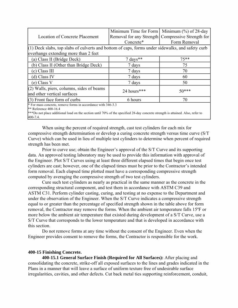
400-14 Removal of Forms. Use the table below as the criterion for minimum time or compressive strength required before removal of forms or supports. When using the time period criterion, include in the time period all days except days in which the temperature falls below 40ºF. Use the specified 28-day minimum compressive strength value as stated in 346-3.1 for each Class of Concrete utilized.
Location of Concrete Placement Minimum Time for Form Removal for any Strength
Concrete*
Minimum (%) of 28-day Compressive Strength for
Form Removal (1) Deck slabs, top slabs of culverts and bottom of caps, forms under sidewalks, and safety curb overhangs extending more than 2 feet (a) Class II (Bridge Deck) 7 days** 75** (b) Class II (Other than Bridge Deck) 7 days 75 (c) Class III 7 days 70 (d) Class IV 7 days 60 (e) Class V 7 days 50 (2) Walls, piers, columns, sides of beams and other vertical surfaces
24 hours*** 50***
(3) Front face form of curbs 6 hours 70 * For mass concrete, remove forms in accordance with 346-3.3 ** Reference 400-16.4 ***Do not place additional load on the section until 70% of the specified 28-day concrete strength is attained. Also, refer to 400-7.4. When using the percent of required strength, cast test cylinders for each mix for compressive strength determination or develop a curing concrete strength versus time curve (S/T Curve) which can be used in lieu of multiple test cylinders to determine when percent of required strength has been met. Prior to curve use; obtain the Engineer’s approval of the S/T Curve and its supporting data. An approved testing laboratory may be used to provide this information with approval of the Engineer. Plot S/T Curves using at least three different elapsed times that begin once test cylinders are cast; however, one of the elapsed times must be prior to the Contractor’s intended form removal. Each elapsed time plotted must have a corresponding compressive strength computed by averaging the compressive strength of two test cylinders. Cure such test cylinders as nearly as practical in the same manner as the concrete in the corresponding structural component, and test them in accordance with ASTM C39 and ASTM C31. Perform cylinder casting, curing, and testing at no expense to the Department and under the observation of the Engineer. When the S/T Curve indicates a compressive strength equal to or greater than the percentage of specified strength shown in the table above for form removal, the Contractor may remove the forms. When the ambient air temperature falls 15ºF or more below the ambient air temperature that existed during development of a S/T Curve, use a S/T Curve that corresponds to the lower temperature and that is developed in accordance with this section. Do not remove forms at any time without the consent of the Engineer. Even when the Engineer provides consent to remove the forms, the Contractor is responsible for the work.
400-15 Finishing Concrete. 400-15.1 General Surface Finish (Required for All Surfaces): After placing and consolidating the concrete, strike-off all exposed surfaces to the lines and grades indicated in the Plans in a manner that will leave a surface of uniform texture free of undesirable surface irregularities, cavities, and other defects. Cut back metal ties supporting reinforcement, conduit,
and other appurtenances a minimum of 1 inch from finished surface. After removing excess mortar and concrete and while the concrete is still in a workable state, carefully tool all construction and expansion joints. Leave joint filler exposed for its full length with clean edges. Ensure that finished work in addition to that specified above is compatible and complementary to the class of surface finish required. Remove all laitance, loose material, form oil and curing compound from exposed surfaces that do not require forming and from exposed surfaces requiring forming, after form removal. Remove fins and irregular projections flush with the surface. Clean, saturate with water, and fill all holes, tie cavities, honeycomb, chips and spalls. Prior to filling, prepare the surface to ensure that patching mortar will bond to the existing concrete. Exercise care during the roughening process to prevent excessive defacement and damage to the surface of the existing concrete. Use patching mortar blended from the mix ingredients of the existing concrete. Ensure the patching mortar closely matches the color of the existing concrete when fully cured. As an alternative, mortar consisting of the following materials may be used: 4 parts of ordinary gray portland cement, 1/2 part of white portland cement, 1 part of fly ash and 2 to 4 parts of sand. The blended mortar must closely match the color of the filled element once fully cured and the proportion of white portland cement may be adjusted to achieve as close a match as possible. Regardless of the type patching mortar used, provide a mortar surface closely resembling the existing surface. Cure the newly placed mortar using a curing blanket or a Type I clear curing compound in accordance with 400-16. In the event unsatisfactory surfaces are obtained, repair these surfaces by methods approved by the Engineer or the affected concrete will be rejected. Repair any surface or remove rejected concrete at no expense to the Department. 400-15.2 Surface Finishes: 400-15.2.1 General: In addition to the general surface work specified for all exposed concrete surfaces, the Engineer may require one of the classes of surface finish listed below. For all such exposed surfaces, begin finish work for the applicable class specified, along with the general finish work, immediately after removal of the forms. In order to further ensure the required quality of the finish, remove forms no later than the minimum time specified for the forms to remain in place. Satisfactorily repair finished concrete surfaces which are subsequently disfigured or discolored at no expense to the Department. Provide the required class of surface finish for the various items of structural concrete as shown in the Plans. 400-15.2.2 Class 1 Surface Finish: As soon as the pointing has sufficiently set, thoroughly saturate the exposed surfaces with water, and rub them with a medium coarse carborundum stone. Continue rubbing until the surface has been ground to a paste and remove all form marks, irregularities, and projections. In this process, do not introduce any additive material other than water. After the rubbing has produced a smooth surface of uniform color, allow the material which has been ground to a paste to reset under proper curing conditions. Subsequently, as a second operation, re-saturate the concrete surfaces with water, and thoroughly rub them with a fine carborundum stone. Continue this rubbing until the surface has a smooth, fine grain texture of uniform color. The Contractor may substitute a Class 5 applied finish coating in accordance with 400-15.2.6 as an alternate surface finish on all areas where Class 1 surface finish is specified.
400-15.2.3 Class 2 Surface Finish: As soon as pointing has sufficiently set, thoroughly saturate the exposed concrete surfaces with water and rub them with a medium coarse carborundum stone. Continue rubbing until the surface has been ground to a paste and remove all form marks, irregularities, and projections. In this process, do not introduce any additive material other than water. After rubbing has produced a smooth surface finish, of uniform color, carefully brush the material which has been ground to a paste to a uniform texture, and allow it to reset under proper curing conditions. Carefully protect these surfaces from disfigurement and discoloration during subsequent construction operations. 400-15.2.4 Class 3 Surface Finish: Where this surface finish is specified, use forms with a form liner. Where specified or required on the Plans, use No. 89 coarse aggregate for concrete. After concrete has been placed in the forms and compacted, finish all exposed surfaces which are not contained by the forms to produce a surface texture as nearly equal to that produced by the form as practicable. Generally, finish unformed surfaces to a smooth, dense surface with a steel trowel. Perform all work, including general surface finish work, in a manner that will preserve the same surface texture and color produced by the form liner. Pointed areas may be rubbed with a dry carborundum stone. 400-15.2.5 Class 4 Deck Finish: 400-15.2.5.1 General: Apply a Class 4 finish on bridge decks and concrete approach slabs. On Short Bridges (bridges having a length less than or equal to 100 ft), and on Miscellaneous Bridges (Pedestrian, Trail and Movable Spans) regardless of length, meet the finish and smoothness requirements of 400-15.2.5.2 and 400-15.2.5.4. On Long Bridges (bridges having a length greater than 100 ft) meet the finish and smoothness requirements of 400-15.2.5.3 and 400-15.2.5.5. When an existing bridge deck is widened, see the Plans for the finish and smoothness requirements of the existing bridge deck and its new widened section. After meeting the screeding requirements of 400-7.13 and curing requirements of 400-16 and the smoothness requirements, herein, groove the bridge deck and approach slabs. Regardless of bridge length, finish decks with less than 2 1/2 inches of top cover in accordance with the requirements for Short Bridges. 400-15.2.5.2 Plastic Surface Finish for Short and Miscellaneous Bridges: After screeding is completed, check the surface of the plastic concrete with a 10 foot straightedge, positioning and half-lapping the straightedge parallel to the centerline to cover the entire surface. Immediately correct deficiencies of more than 1/8 inch, measured as an ordinate between the surface and the straightedge. Finish the concrete surface to a uniform texture using a burlap drag, fine bristle broom or float. Finish the deck to a smooth surface having a sandy texture without blemishes, marks or scratches deeper than 1/16 inch. 400-15.2.5.3 Plastic Surface Finish for Long Bridges: Do not moisten, manually float or apply texture to the concrete surface after the screed, with attached smoothing device, has passed unless correction of isolated surface irregularities is warranted and this should be done as soon as possible after screeding while the concrete is plastic. Correct all flaws such as cavities, blemishes, marks, or scratches that will not be removed by planing. If the Engineer permits the addition of water when correcting flaws, apply moisture to the concrete surface only if required and only in the immediate vicinity
of the isolated irregularity. Apply a quantity of moisture not greater than what is needed to facilitate correction of the irregularity and apply only a fog mist, above the concrete surface, by power driven spray equipment approved by the Engineer. 400-15.2.5.4 Smoothness Requirements for Short Bridges and Miscellaneous Bridges (including approach slabs): Perform a final straightedge check with a 10 foot straightedge, positioning and half-lapping the straightedge parallel to the centerline, approximately 5 feet apart to cover the entire surface. Correct all irregularities greater than 3/16 inch measured as an ordinate to the straightedge, by grinding. Perform grinding by the abrasive method using hand or power tools or by machine, to leave a smooth surface within a 1/8 inch tolerance. 400-15.2.5.5 Smoothness Evaluation and Concrete Surface Planing, Long Bridges (including approach slabs): Prior to planing, provide a smoothness evaluation of the completed bridge deck and exposed concrete surfaces of approach slabs by a computerized Cox California-type profilograph in accordance with the criteria herein and FM 5-558E. Furnish this evaluation through an independent provider approved by the Engineer, using equipment calibrated by the Engineer. All bridge deck and concrete approach slab surfaces to within 2 feet of gutter lines are subject to this smoothness evaluation. Prior to initial profilograph testing, complete work on the bridge deck and approach slabs. Thoroughly clean and clear the bridge deck and approach slab areas to be evaluated for smoothness of all obstructions and provide the smoothness evaluation. Ensure that no radio transmissions or other activities that might disrupt the automated profilograph equipment are allowed during the evaluation. Average the Profile Index Value for the bridge deck, including the exposed concrete surfaces of the approach slabs, for the left and right wheel path of each lane. The maximum allowable Profile Index Value for acceptable smoothness is 10 inches per mile utilizing the 0.2 inch blanking band. Apply these criteria to a minimum of 100 feet of each lane. Additionally, correct individual bumps or depressions exceeding a cutoff height of 0.3 inch from a chord of 25 feet (see ASTM E1274) on the profilograph trace. Ensure that the surface meets a 1/4 inch in 10 feet straightedge check made transversely across the deck and approach slabs if determined necessary by the Engineer. Provide additional profilograph testing as necessary following longitudinal planing and any other actions taken to improve smoothness, until a profile meeting the acceptance criteria is obtained. Regardless of whether expansion joints are installed before or after deck planing is complete, plane off the concrete deck surface to a minimum depth of 1/4 inch and also meet or exceed the profilograph smoothness criteria. Longitudinally plane the entire bridge deck and exposed concrete surfaces of the approach slabs using a self-propelled planing machine with gang mounted diamond saw cutting blades specifically designed for such work. Use the profilograph generated smoothness data, to establish the optimum planing machine settings. Plane the deck surface to within 2 feet of the gutter line so that there is a smooth transition, without vertical faces or sudden surface discontinuities, from the fully planed surface to the unplaned surface. Use a machine with a minimum wheel base length of 15 feet, constructed and operated in such manner that it does not cause strain or damage to deck or approach slab surfaces, excessive ravels, aggregate fractures or spalling. The equipment shall be approved by the Engineer. Perform longitudinal planing parallel to the roadway centerline, and provide a consistent, textured surface. Clean the surface of all slurry/debris generated during this work concurrently with operation of the machine.
After the deck has been planed the minimum 1/4 inch, reevaluate the surface smoothness using the profilograph testing described above. Perform cycles of planing and profilograph retesting as necessary until the deck and exposed concrete surfaces of approach slabs are in compliance with the smoothness criteria but do not exceed the maximum concrete removal depth of 1/2 inch. 400-15.2.5.6 Grooving: After the concrete surface profile, as required by 400-15.2.5, has been accepted by the Engineer, and prior to opening the bridge to traffic, groove the bridge deck and approach slabs perpendicular to the centerline of the structure. Do not groove the deck surface of pedestrian or trail bridges unless otherwise shown in the Contract Documents. Cut grooves into the hardened concrete using a mechanical saw device which will leave grooves nominally 1/8 inch wide and 3/16 inch deep. Space the grooves apart in random spacing center of grooves in the following sequence: 3/4 inch, 1-1/8 inch, 5/8 inch, 1 inch, 5/8 inch, 1-1/8 inch, 3/4 inch in 6 inch repetitions across the width to be grooved in one pass of the mechanical saw device. One 6 inch sequence may be adjusted by 1/4 sequence increments to accommodate various cutting head widths provided the general pattern is carried out. The tolerance for the width of the grooves is plus 1/16 inch to minus 0 inch and the tolerance for the depth of grooves is plus or minus1/16 inch. The tolerance for the spacing of the grooves is plus or minus1/16 inch. Cut grooves continuously across the deck or approach slab to within 18 inches of gutter lines at barrier rail, curb line and median divider. At skewed metal expansion joints in bridge deck surfaces, adjust groove cutting by using narrow width cutting heads so that all grooves of the bridge deck surface or approach slab surface end within 6 inches, measured normal to centerline of the joint, leaving no ungrooved surface adjacent to each side of the joint greater than 6 inches in width. Ensure that the minimum distance to the first groove, measured normal from the edge of the concrete joint or from the junction between the concrete and the metal leg of the armored joint angle, is 1 inch. Produce grooves that are continuous across construction joints or other joints in the concrete surface less than 1/2 inch wide. Apply the same procedure described above where the gutter lines at barrier rails, curb lines and median dividers are not parallel to the centerline of the bridge to maintain the 18 inches maximum dimension from the grooves to the gutter line. Cut grooves continuously across formed concrete joints. 400-15.2.6 Class 5 Applied Finish Coating: 400-15.2.6.1 General: Place an applied finish coating upon all concrete surfaces where the Plans indicate Class 5 Applied Finish Coating. Apply the finish coating after completion of the general surface work specified for all exposed concrete surfaces. Select an Applied Finish Coating from the APL meeting the requirements of Section 975. 400-15.2.6.2 Material: For the coating material, use a commercial product designed specifically for this purpose. Use only coating material that is manufactured by one manufacturer and delivered to the job site in sealed containers bearing the manufacturer’s original labels. Submit a copy of the manufacturer’s printed instructions to the Engineer. 400-15.2.6.3 Surface Preparation: Prepare the surface prior to the application of an applied finish coating by providing a surface finish in accordance with the requirements of 400-15.1. The Engineer will not require surface voids that are 1/4 inch or less in width and depth to be grouted prior to application of the finish coating. Fill surface void larger than 1/4 inch in width and depth an approved high strength, non metallic, non shrink grout meeting the requirements of Section 934, mixed and applied in accordance with the
manufacturer’s recommendations. Apply the grout by filling the surface voids using burlap pads, float sponges, or other acceptable methods. As soon as the grout has taken its initial set, brush the surface to remove all loose grout, leaving the surface smooth and free of any voids. Ensure that the surface to be coated is free from efflorescence, flaking coatings, curing compound, dirt, oil, and other substances deleterious to the applied finish coating. Prior to application of the finish coating onto precast or cast-in-place concrete surfaces, test the concrete surface at 30 foot intervals for the presence of curing compound using one or two drops of muriatic acid placed on the concrete surface. If curing compound is present, there will be no reaction between the acid and the concrete. If there is no reaction, remove the compound by pressure washing the concrete surfaces. Prepare the surfaces in accordance with the manufacturer’s recommendations, and ensure that they are in a condition consistent with the manufacturer’s requirements. Clean surfaces of existing structures in accordance with 400-19. 400-15.2.6.4 Application: Apply the finish coating utilizing a method recommended by the manufacturer. When applying the finish coating by spraying, supply heavy duty spray equipment capable of maintaining a constant pressure necessary for proper application. Mix and cure all coating materials in accordance with the manufacturer’s printed instructions. Apply the finished coating at a rate of 50, plus or minus 10 square feet per gallon. 400-15.2.6.5 Finished Product: Produce a texture of the completed finish coat that is generally similar to that of rubbed concrete. Ensure that the completed finished coating is tightly bonded to the structure and presents a uniform appearance and texture. If necessary, apply additional coats to produce the desired surface texture and uniformity. Upon failure to adhere positively to the structure without chipping, flaking, or peeling, or to attain the desired surface appearance, remove coatings entirely from the structure, and reapply the finish coating after surface preparation until achieving the desired finished product. Do not allow the average thickness of the completed finish coating to exceed 1/8 inch. 400-15.2.6.6 Material Tests and Certification: Before any portion of any shipment of finish coating is applied on the project, furnish the Engineer with a certificate from the manufacturer attesting that the commercial product furnished conforms to the same formula as that previously subjected to the tests specified in Section 975. In addition, submit the following product analysis, obtained from the manufacturer, for each batch of the material used: 1. Weight per gallon. 2. Consistency (Krebs Units). 3. Weight percent pigment. 4. Weight percent vehicle solids. 5. Infra-red spectra of vehicle solution. 400-15.2.7 Final Straightedging for Surfaces to Receive Asphalt Concrete Surface: Test the slab surfaces of poured-in-place decks which are to be surfaced with an asphalt concrete wearing course for trueness with a 10 foot straightedge, as specified above. As an exception, correct only irregularities of more than 1/4 inch measured as an ordinate (either above or below the general contour of the surface). The Engineer will not require belting or brooming of slabs that are to be surfaced with an asphalt concrete wearing course. For curing, meet the requirements specified for other deck slabs. 400-15.2.8 Finishing Bridge Sidewalks: Finish bridge sidewalks in accordance with the applicable requirements of Section 522.
400-16 Curing Concrete. 400-16.1 General: Cure cast-in-place and precast (non-prestressed) concrete as required herein for a minimum duration of 72 hours. If forms are loosened or removed before the 72 hour curing period is complete, expand the curing to cover these surfaces by either coating with curing compound or extending the continuous moist cure area. Until curing has begun, retain concrete surface moisture at all times by maintaining a surface moisture evaporation rate less than 0.1 pound per square foot per hour. Periodically, at the site of concrete placement prior to and during the operation, measure the ambient air temperature, relative humidity and wind velocity with industrial grade weather monitoring instruments to determine the on-site evaporation rate. If the evaporation is, or is likely to become 0.1 pound per square foot per hour or greater, employ measures to prevent moisture loss such as application of evaporation retarder, application of supplemental moisture by fogging or reduction of the concrete temperature during batching. Compute the evaporation rate by using the nomograph in the ACI manual of Concrete Practice Part 2, Section 308R Guide to Curing Concrete, or by using an evaporation rate calculator approved by the Engineer. 400-16.2 Methods: Except where other curing methods are specified, select from the following options the chosen method(s) for curing all concrete components. 1. Continuous Moisture: Place burlap on the surface and keep it continuously saturated for the curing period by means of soaker hoses or automatic sprinklers. Water flow may be metered to cycle repetitively for five minutes on and five minutes off during the 72 hour curing period. Do not apply moisture manually. If side forms are loosened or removed during the curing period, extend the burlap so as to completely shield the sides of the members. 2. Membrane Curing Compound: Apply a white Type 2 curing compound to all surfaces at a uniform coverage as recommended by the manufacturer but not less than 0.06 gallon per square yard. Allow surfaces covered by the membrane curing compound to remain undisturbed for the curing period. Recoat any cracks, checks or other defects in the membrane seal which are detected during the curing period within one hour. If side forms are loosened during the curing period, maintain surface moisture and remove the forms within one hour and immediately coat the formed surfaces with a membrane curing compound. Bottom surfaces shall be similarly coated after removal of or from the forms. If curing compound is to be applied by spraying, use a compressor driven sprayer of sufficient size to provide uniform mist. Standby equipment is required in case of mechanical failure and hand held pump-up sprayers may be used only as standby equipment. 3. Curing Blankets: Curing blankets may be used for curing the top surfaces of members while the member side forms remain in place. Do not use curing blankets which have been torn or punctured. Securely fasten all edges to provide as tight a seal as practical. Should the system fail to maintain a moist condition on the concrete surface, discontinue use of the blankets and continue curing using another method. Keep curing blankets in place for the duration of the curing period. 4. Accelerated Cure: a. General: Accelerated curing of the concrete can be achieved by use of either low pressure steam curing, radiant heat curing or continuous moisture and heat curing. If accelerated curing is completed before the 72 hour curing period has elapsed, continue curing for the remaining part of the 72 hour curing period in accordance with one of the curing methods listed above.
If accelerated curing is used, furnish temperature recording devices that will provide accurate, continuous and permanent records of the time and temperature relationship throughout the entire curing period. Provide one such recording thermometer for each 200 feet of placement length or part thereof. Initially calibrate recording thermometers and recalibrate at least annually. The preheating period shall equal or exceed the time of initial set as determined by ASTM C403 and shall not be less than 4 hours. When the ambient air temperature is above 50ºF, allow the member to remain undisturbed in the ambient air for the preheating period. If the ambient air temperature is below 50ºF, apply heat during the preheating period to hold the air surrounding the member at a temperature of 50 to 90ºF. To prevent moisture loss from exposed surfaces during the preheating period, enclose members as soon as possible after casting or keep the surfaces wet by fog mist or wet blankets. Use enclosures for heat curing that allow free circulation of heat about the member with a minimum moisture loss. The use of tarpaulins or similar flexible covers may be used provided they are kept in good repair and secured in such a manner to prevent the loss of heat and moisture. Use enclosures that cover the entire placement. During the application or removal of the heat, do not allow the temperature rise or fall within the enclosure to exceed 40ºF per hour. Do not allow the curing temperature throughout the enclosure to exceed 160ºF. Maintain the curing temperature within a temperature range of 130 to 160ºF until the concrete has reached the required form removal strength for precast and cast-in-place components or the required release strength for prestressed concrete components. b. Low-Pressure Steam: The steam used shall be in a saturated condition. Do not allow steam jets to impinge directly on the concrete, test cylinders, or forms. Cover control cylinders to prevent moisture loss and place them in a location where the temperature is representative of the average temperature of the enclosure. c. Curing with Radiant Heat: Apply radiant heat by means of pipes circulating steam, hot oil or hot water, or by electric heating elements. Do not allow the heating elements to come in direct contact with the concrete or the forms. Distribute sources of heat in a manner that will prevent localized high temperatures above 160ºF. To prevent moisture loss during curing, keep the exposed surfaces wet by fog mist or wet blankets. d. Continuous Moisture and Heat: This method consists of heating the enclosure in combination with the continuous moisture method described above. In addition to the curing blankets, an auxiliary cover for retention of the heat will be required over the entire placement. Support this cover at a sufficient distance above the placement being cured to allow circulation of the heat. 400-16.3 Silica Fume Concrete: Cure silica fume concrete a minimum of 72 hours using continuous moisture cure. No substitution of alternative methods nor reduction in the time period is allowed. After completion of the 72 hour curing period, apply a membrane curing compound to all concrete surfaces. Apply curing compound according to 400-16.2. 400-16.4 Bridge Decks and Approach Slabs: Cure bridge decks and approach slabs for a duration of seven days. Apply a membrane curing compound to the top surface in accordance with 400-16.2 using a compressor driven sprayer. In general, apply curing compound when the surface is damp and after all pooled water has evaporated. For Short bridges, begin applying curing compound immediately after the initially placed concrete has been floated, straightedged, textured and a damp surface condition exists and continue applying compound as concrete
placement progresses with as little interruption as possible until the entire top surface has been coated with compound. For Long bridges, begin applying curing compound to the initially placed concrete as soon as a damp surface condition exists and continue applying compound as concrete placement progresses with as little interruption as possible until the entire top surface has been coated with compound. For all bridges, the elapsed time between the initial placement of deck or approach slab concrete and the completed application of curing compound must not exceed 120 minutes. The 120 minute limit may be extended by the Engineer if project specific factors (cool temperatures, high humidity, retarding admixtures, etc.) prolong wet surface conditions. Prior to the first deck or approach slab placement, submit to the Engineer the method that will be used to periodically measure the rate of application of curing compound in, gallons per square foot as the concrete placement progresses. Prior to the placement of each deck or approach slab, submit to the Engineer the anticipated quantity of curing compound in gallons along with the corresponding square feet of concrete to be covered to meet the coverage rate in 400-16.2. Compute the actual quantity of curing compound applied at the conclusion of each concrete placement and submit the quantity to the Engineer. Apply the curing compound from a work platform. Place curing blankets on all exposed surfaces which are not formed as soon as possible with minimal effect on the surface texture. Place the curing blankets with sufficient overlapping seams to form an effective moisture seal. Before using curing blankets, mend tears, splits, or other damage that would make them unsuitable. Discard curing blankets that are not repairable. Wet all curing blankets immediately after satisfactorily placing them and maintain them in a saturated condition throughout the seven day curing period. Supply sufficient quantity of water meeting the requirements of Section 923 at the job site for wetting the blankets. Where a bridge deck or approach slab is to be subjected to walking, wheeling or other approved construction traffic within the seven day curing period, protect the curing blankets and the concrete surface from damage by placing wooden sheeting, plywood or other approved protective material in the travel areas. When the ends of the curing blankets are rolled back to permit screeding of adjacent concrete, keep the exposed surfaces wet throughout the period of exposure. Bridge deck bottom and side forms may be removed after 72 hours upon compliance with 400-14. Approach slab side forms may be removed after 72 hours. Apply membrane curing compound to all surfaces stripped of forms within one hour of loosening. Apply curing compound according to 400-16.2. 400-16.5 Construction Joints: Cure construction joint areas using either the continuous moisture or curing blankets method. 400-16.6 Traffic Barriers, Railings, Parapets and End Post: Ensure concrete is cured in accordance with 400-16.2(2), except that a clear Type 1-D curing compound that must contain a fugitive dye may be used in lieu of Type 2. If Type 1-D is used, its removal per 400-15.1 during finishing is not required. When construction is by the slip form method, coat all concrete surfaces with a curing compound that meets the requirements of 925-2, either within 30 minutes of extrusion or before the loss of water sheen, whichever occurs first. Ensure a curing compound coating period of not less than seven days after application. Prior to each concrete placement, submit to the Engineer the method that will be used to periodically measure the rate of application in gallons per square foot. Also, prior to each placement, submit to the Engineer the anticipated quantity of curing compound in gallons that will be used to meet the coverage rate
specified in 400-16.2 along with the corresponding square footage of barriers, railings, parapets and end posts to be coated with that quantity. Measure the actual quantity of curing compound that is applied during each concrete placement and submit the quantity to the Engineer. Applied finish coatings, that are on the APL and that are flagged as permitted for use as a curing compound, may be used in lieu of a curing compound. If an applied finish coating is used in lieu of a curing compound, have a backup system that is in full compliance with 400-16.2(2) available at all times to ensure that an effective alternative system will be immediately available if the applied finish coating cannot be applied within 30 minutes of extrusion or before the loss of water sheen. 400-16.7 Removal of Membrane Curing Compounds: Provide the longest possible curing duration; however, remove curing compound on portions of members to be bonded to other concrete. Compounds may be removed by either sand or water blasting. Water blasting requires the use of water meeting the requirements of Section 923 and a minimum nozzle pressure of 2,900 psi.
400-17 Protection of Concrete. 400-17.1 Opening to Traffic: Do not open concrete bridge decks, approach slabs, or culverts to traffic for at least 14 days after concrete placement. During placement operations, concrete may be wheeled across previously placed slabs after they have set for 24 hours and plank runways are used to keep the loads over the beams. 400-17.2 Storing Materials on Bridge Slabs: Do not store heavy equipment or material, other than light forms or tools, on concrete bridge slabs or approach slabs until 14 days after they have been placed. Obtain approval from the Engineer prior to storing materials, tools or equipment on bridge decks at any time. Disperse any such loads to avoid overloading the structure. 400-17.3 Time of Placing Superstructure: Do not place the weight of the superstructure or beams on concrete substructure elements for at least 10 days after placement. 400-17.4 Alternate Procedure: As an alternative to the time delay periods set forth in 400-17.1 and 400-17.3, test cylinders may be prepared and tested by the Contractor in accordance with 346-5 and a determination made using one of the following methods: 1. When the cylinder test results indicate the minimum 28 day compressive strength shown in the Plans, concrete bridge decks, approach slabs, and culverts may be opened to traffic or the superstructure and beams may be placed on caps. 2. Provide signed and sealed calculations, prepared by a Specialty Engineer, demonstrating that the concrete caps can safely support the weight of the girders for the current concrete strength to the Engineer for approval. In any event, comply with the curing provisions of 400-16.
400-18 Precast Planks, Slabs, and Girders. 400-18.1 General: Where so shown in the Contract Documents, the Contractor may construct concrete planks, slabs, girders, and other structural elements by precasting. In general, use a method that consists of casting structural elements in a casting yard, curing as specified in 400-16, transporting them to the site of the work, installing them on previously prepared supports and, where so shown in the Plans, joining them with poured-in-place slabs or keys. Handle and install precast prestressed members as specified in Section 450.
400-18.2 Casting: Cast precast elements on unyielding beds or pallets. Use special care in casting the bearing surfaces on both the elements and their foundations in order that these surfaces shall coincide when installing the elements. Check bearing surfaces on casting beds with a level and a straightedge prior to the casting. Similarly check corresponding surfaces on the foundations during finishing operations. 400-18.3 Poured-in-Place Keys: Where precast elements are to be joined with poured-in-place keys, carefully align the elements prior to pouring the keys. 400-18.4 Surface Finish: Finish the surface as specified in 400 15, except that where precast slabs and poured-in-place keys form the riding surface, give the entire surface a broomed finish. 400-18.5 Moving, Placing, and Opening to Traffic: Reinforced precast members may be moved from casting beds, placed in the structure, and opened to traffic at the ages shown in the following table:
Handling from casting beds to storage areas .............. 7 days Placing in structure ................................................... 14 days
Opening to traffic: Precast elements ........................................................ 14 days Cast-in-place slabs over precast girders ................... 14 days Cast-in-place keys joining precast slabs ..................... 7 days
As an alternate procedure, in lieu of the time delay periods set forth above, test beams may be cast from representative concrete, and cure them identically with the concrete in the corresponding structural component. Test the test beams in accordance with ASTM C31 and ASTM C78. When the test results indicate a flexural strength of 550 psi, or more, any of the operations listed above may proceed without completing the corresponding time delay period. 400-18.6 Setting Prestressed Slabs: Before permitting construction equipment on the bridge to erect slab units, submit sketches showing axle loads and spacing and a description of the intended method of setting slab units to the Engineer for approval. Do not use axle loads, spacing, and methods of setting which produce stresses in the slab units greater than the allowable stress. 400-18.7 Protection of Precast Elements: The Contractor is responsible for the safety of precast elements during all stages of construction. The Engineer will reject any precast elements that become cracked, broken, seriously spalled, or structurally impaired. Remove rejected precast elements from the work at no expense to the Department. 400-18.8 Form Material: Form material used to form hollow cores may be left in place. Ensure that the form material is neutral with respect to the generating of products harmful to the physical and structural properties of the concrete. The Contractor is responsible for any detrimental effects resulting from the presence of the form material within the precast element.
400-19 Cleaning and Coating Concrete Surfaces of Existing Structures. For the purposes of this article, an existing structure is one that was in service prior to the start of the project to which this specification applies. For existing structures, clean concrete surfaces that are designated in the Contract Documents as receiving Class 5 applied finish coating by pressure washing prior to the application of coating. Use pressure washing equipment producing a minimum working pressure of 2,500 psi when measured at or near the nozzle. Do not damage or gouge uncoated concrete surfaces or previously coated concrete surfaces during cleaning operations. Remove all previously applied coating that is no longer adhering to the
concrete or that is peeling, flaking or delaminating. Ensure that after the pressure wash cleaning and the removal of non-adherent coating, that the cleaned surfaces are free of efflorescence, grime, mold, mildew, oil or any other contaminants that might prevent proper adhesion of the new coating. After cleaning has been successfully completed, apply Class 5 Applied Finish Coating in accordance with 400-15.2.6 or as otherwise specified in the Plans.
400-20 Approach Slabs. Construct approach slabs at the bridge ends in accordance with the applicable requirements of Section 350 using Class II (Bridge Deck) concrete. Place the reinforcement as specified in 350-7 and Section 415.
400-21 Disposition of Cracked Concrete. 400-21.1 General: The disposition of cracked concrete is described in this Article and applies to all cast-in-place concrete members, and once installed, to the precast and prestressed concrete members that are produced in accordance with 410, 450, 521, 534, 548 and 641. 400-21.2 Investigation, Documentation and Monitoring: The Engineer will inspect concrete surfaces as soon as surfaces are fully visible after casting, with the exception of surfaces of precast concrete products produced in offsite plants, between 7 and 31 days after the component has been burdened with full dead load, and a minimum of 7 days after the bridge has been opened to full unrestricted traffic. The Engineer will measure the width, length and depth of each crack and establish the precise location of the crack termination points relative to permanent reference points on the member. The Engineer will determine if coring of the concrete is necessary when an accurate measurement of crack depth cannot be determined by use of a mechanical probe. The Engineer will monitor and document the growth of individual cracks at an inspection interval determined by the Engineer to determine if cracks are active or dormant after initial inspection. The Engineer will perform all final bridge deck crack measurements once the deck is free of all debris and before transverse grooves are cut and after planing is complete for decks that require planing. Provide the access, equipment and personnel needed for the Engineer to safely perform this work at no expense to the Department. Core cracks for use by the Engineer in locations and to depths specified by the Engineer at no expense to the Department. 400-21.3 Classification of Cracks: The Engineer will classify cracks as either nonstructural or structural and determine the cause. In general, nonstructural cracks are cracks 1/2 inch or less deep from the surface of the concrete; however, the Engineer may determine that a crack greater than 1/2 inch deep is nonstructural. In general, structural cracks are cracks that extend deeper than 1/2 inch. As an exception, all cracks in concrete bridge decks that are supported by beams or girders will be classified as nonstructural and repair will be in accordance with 400-21.5.1. However, if the Engineer determines that repair under 400-21.5.1 is unacceptable, repair in accordance with 400-21.5.2. A crack that is fully or partially underwater at any time during its service life will be classified as a structural crack unless the Environment note on the General Notes sheet in the Plans categorizes the substructure as slightly aggressive, in which case, the nonstructural crack criteria may apply as determined by the Engineer. Review and comment on the Engineer’s crack classification; however, the Engineer will make the final determination.
400-21.4 Nonstructural Cracking Significance: The Engineer will determine the Cracking Significance. The Cracking Significance will be determined on the basis of total crack surface area as a percentage of total concrete surface area. Cracking significance will be categorized as Isolated, Occasional, Moderate or Severe according to the criteria in Tables 1 and 2. Cracking Significance will be determined on a LOT by LOT basis. A LOT will typically be made up of not more than 100 square feet and not less than 25 square feet of concrete surface area for structures other than bridge decks or typically not more than 400 square feet or not less than 100 square feet for bridge decks. A LOT will not extend beyond a single Elevation Range as shown in Table 1 or 2. Review and comment on the Engineer’s determination of Cracking Significance; however, the Engineer will make the final determination. 400-21.5 Repair Method: Repair or remove and replace cracked concrete as directed by the Engineer. Additional compensation or a time extension will not be approved for repair or removal and replacement of cracked concrete when the Engineer determines the cause to be the responsibility of the Contractor. 400-21.5.1 Nonstructural Cracks: Repair each crack using the method as determined by the Engineer for each LOT in accordance with Table 1 or 2. When further investigation is required to determine repair or rejection, either remove and replace the cracked concrete or provide a structural evaluation signed and sealed by the Contractor’s Engineer of Record that includes recommended repair methods and a determination of structural capacity and durability to the Engineer. Upon approval by the Engineer, repair the cracked concrete. Upon approval by the Engineer use epoxy injection in accordance with Section 411 to repair cracks in a member inside a dry cofferdam prior to flooding of the cofferdam. “Reject and Replace” in Table 1 or 2 means there is no acceptable repair method. 400-21.5.2 Structural Cracks: Provide a structural evaluation signed and sealed by the Contractor’s Engineer of Record that includes recommended repair methods and a determination of structural capacity and durability to the Engineer. Upon approval by the Engineer, repair the cracked concrete. Complete all repairs to cracks in a member inside a cofferdam prior to flooding the cofferdam.
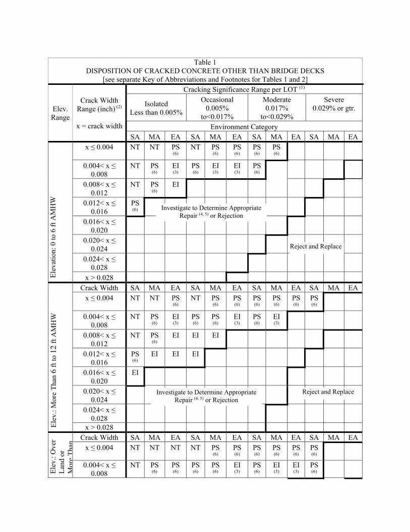
Table 1
DISPOSITION OF CRACKED CONCRETE OTHER THAN BRIDGE DECKS [see separate Key of Abbreviations and Footnotes for Tables 1 and 2]
Elev. Range
Crack Width Range (inch) (2)
x = crack width
Cracking Significance Range per LOT (1)
Isolated Less than 0.005%
Occasional 0.005%
to<0.017%
Moderate 0.017%
to<0.029%
Severe 0.029% or gtr.
Environment Category SA MA EA SA MA EA SA MA EA SA MA EA
Ele
vati
on: 0
to 6
ft A
MH
W
x ≤ 0.004 NT NT PS (6)
NT PS (6)
PS (6)
PS (6)
PS (6)
0.004< x ≤ 0.008
NT PS (6)
EI (3)
PS (6)
EI (3)
EI (3)
PS (6)
0.008< x ≤ 0.012
NT PS (6)
EI
0.012< x ≤ 0.016
PS (6)
0.016< x ≤ 0.020
0.020< x ≤ 0.024
0.024< x ≤ 0.028
x > 0.028
Ele
v.: M
ore
Tha
n 6
ft to
12
ft A
MH
W
Crack Width SA MA EA SA MA EA SA MA EA SA MA EA x ≤ 0.004 NT NT PS
(6) NT PS
(6) PS (6)
PS (6)
PS (6)
PS (6)
PS (6)
0.004< x ≤ 0.008
NT PS (6)
EI (3)
PS (6)
PS (6)
EI (3)
PS (6)
EI (3)
0.008< x ≤ 0.012
NT PS (6)
EI EI EI
0.012< x ≤ 0.016
PS (6)
EI EI EI
0.016< x ≤ 0.020
EI
0.020< x ≤ 0.024
0.024< x ≤ 0.028
x > 0.028
Ele
v.: O
ver
Lan
d or
M
ore
Tha
n
Crack Width SA MA EA SA MA EA SA MA EA SA MA EA x ≤ 0.004 NT NT NT NT PS
(6) PS (6)
PS (6)
PS (6)
PS (6)
PS (6)
0.004< x ≤ 0.008
NT PS (6)
PS (6)
PS (6)
PS (6)
EI (3)
PS (6)
EI (3)
EI (3)
PS (6)
Investigate to Determine Appropriate Repair (4, 5) or Rejection
Reject and Replace
Reject and ReplaceInvestigate to Determine Appropriate Repair (4, 5) or Rejection
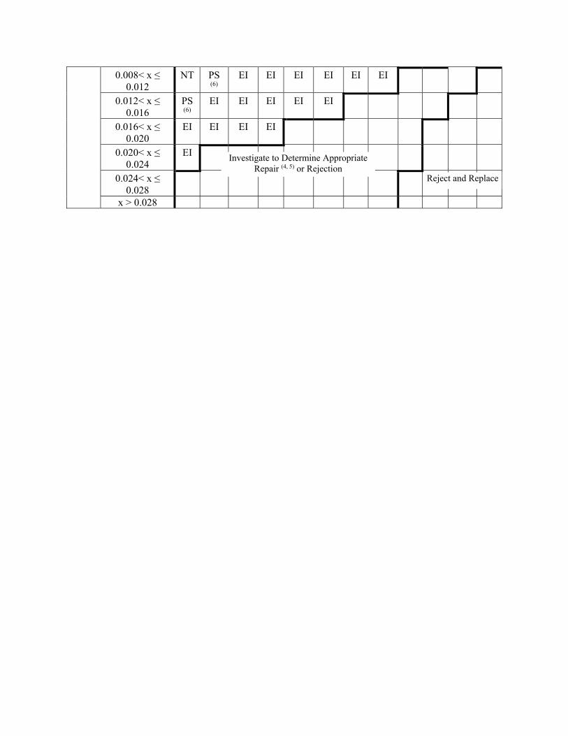
0.008< x ≤ 0.012
NT PS (6)
EI EI EI EI EI EI
0.012< x ≤ 0.016
PS (6)
EI EI EI EI EI
0.016< x ≤ 0.020
EI EI EI EI
0.020< x ≤ 0.024
EI
0.024< x ≤ 0.028
x > 0.028
Investigate to Determine Appropriate Repair (4, 5) or Rejection
Reject and Replace
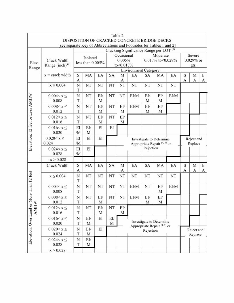
Table 2
DISPOSITION OF CRACKED CONCRETE BRIDGE DECKS [see separate Key of Abbreviations and Footnotes for Tables 1 and 2]
Elev. Range
Crack Width
Range (inch) (2)
x = crack width
Cracking Significance Range per LOT (1)
Isolated less than 0.005%
Occasional 0.005%
to<0.017%
Moderate 0.017% to<0.029%
Severe 0.029% or
gtr. Environment Category
SA
MA EA SA MA
EA SA MA EA SA
MA
EA
Ele
vati
on: 1
2 fe
et o
r L
ess
AM
HW
x ≤ 0.004 NT
NT NT NT NT NT NT NT NT
0.004< x ≤ 0.008
NT
NT EI/M
NT NT EI/M EI/M
EI/M
EI/M
0.008< x ≤ 0.012
NT
NT EI/M
NT EI/M
EI/M EI/M
EI/M
0.012< x ≤ 0.016
NT
NT EI/M
NT EI/M
0.016< x ≤ 0.020
EI/M
EI/M
EI EI
0.020< x ≤ 0.024
EI/M
EI EI
0.024< x ≤ 0.028
EI/M
EI
x > 0.028
Ele
vati
on: O
ver
Lan
d or
Mor
e T
han
12 f
eet
AM
HW
Crack Width SA
MA EA SA MA
EA SA MA EA SA
MA
EA
x ≤ 0.004 NT
NT NT NT NT NT NT NT NT
0.004< x ≤ 0.008
NT
NT NT NT NT EI/M NT EI/M
EI/M
0.008< x ≤ 0.012
NT
NT EI/M
NT NT EI/M EI/M
EI/M
0.012< x ≤ 0.016
NT
NT EI/M
NT EI/M
0.016< x ≤ 0.020
NT
EI/M
EI EI/M
0.020< x ≤ 0.024
NT
EI/M
EI
0.024< x ≤ 0.028
NT
EI/M
x > 0.028
Reject and Replace
Investigate to Determine Appropriate Repair (4, 5) or
Rejection
Reject and Replace
Investigate to Determine Appropriate Repair (4, 5) or
Rejection
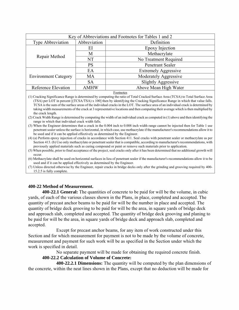
Key of Abbreviations and Footnotes for Tables 1 and 2
Type Abbreviation Abbreviation Definition
Repair Method
EI Epoxy Injection M Methacrylate NT No Treatment Required PS Penetrant Sealer
Environment Category EA Extremely Aggressive MA Moderately Aggressive SA Slightly Aggressive
Reference Elevation AMHW Above Mean High Water Footnotes
(1) Cracking Significance Range is determined by computing the ratio of Total Cracked Surface Area (TCSA) to Total Surface Area (TSA) per LOT in percent [(TCSA/TSA) x 100] then by identifying the Cracking Significance Range in which that value falls. TCSA is the sum of the surface areas of the individual cracks in the LOT. The surface area of an individual crack is determined by taking width measurements of the crack at 3 representative locations and then computing their average which is then multiplied by the crack length.
(2) Crack Width Range is determined by computing the width of an individual crack as computed in (1) above and then identifying the range in which that individual crack width falls.
(3) When the Engineer determines that a crack in the 0.004 inch to 0.008 inch width range cannot be injected then for Table 1 use penetrant sealer unless the surface is horizontal, in which case, use methacrylate if the manufacturer's recommendations allow it to be used and if it can be applied effectively as determined by the Engineer.
(4) (a) Perform epoxy injection of cracks in accordance with Section 411. Seal cracks with penetrant sealer or methacrylate as per Section 413. (b) Use only methacrylate or penetrant sealer that is compatible, according to manufacturer's recommendations, with previously applied materials such as curing compound or paint or remove such materials prior to application.
(5) When possible, prior to final acceptance of the project, seal cracks only after it has been determined that no additional growth will occur.
(6) Methacrylate shall be used on horizontal surfaces in lieu of penetrant sealer if the manufacturer's recommendations allow it to be used and if it can be applied effectively as determined by the Engineer.
(7) Unless directed otherwise by the Engineer, repair cracks in bridge decks only after the grinding and grooving required by 400-15.2.5 is fully complete.
400-22 Method of Measurement. 400-22.1 General: The quantities of concrete to be paid for will be the volume, in cubic yards, of each of the various classes shown in the Plans, in place, completed and accepted. The quantity of precast anchor beams to be paid for will be the number in place and accepted. The quantity of bridge deck grooving to be paid for will be the area, in square yards of bridge deck and approach slab, completed and accepted. The quantity of bridge deck grooving and planing to be paid for will be the area, in square yards of bridge deck and approach slab, completed and accepted. Except for precast anchor beams, for any item of work constructed under this Section and for which measurement for payment is not to be made by the volume of concrete, measurement and payment for such work will be as specified in the Section under which the work is specified in detail. No separate payment will be made for obtaining the required concrete finish. 400-22.2 Calculation of Volume of Concrete: 400-22.2.1 Dimensions: The quantity will be computed by the plan dimensions of the concrete, within the neat lines shown in the Plans, except that no deduction will be made for
weep holes, deck drains, or encroachment of inlets and pipes in box culverts, and no chamfers, scorings, fillets, or radii 1 1/2 in2 or less in cross-sectional area will be taken into account. 400-22.2.2 Pay Quantity: The quantity to be paid for will be the original plan quantity, measured as provided in 400-22.2.1, except that where the Plans call for an estimated quantity of miscellaneous concrete for contingent use, the contingent concrete will be measured as the actual quantity in place and accepted. 400-22.2.3 Items not Included in Measurement for Payment: No measurements or other allowances will be made for work or material for forms, falsework, cofferdams, pumping, bracing, expansion-joint material, etc. The volume of all materials embedded in the concrete, such as structural steel, pile heads, etc., except reinforcing steel, will be deducted when computing the volume of concrete to be paid for. For each foot of timber pile embedded, 0.8 cubic feet of concrete will be deducted. The cost of furnishing and placing dowel bars shall be included in the Contract unit price for the concrete. 400-22.2.4 Deck Girders and Beam Spans: In computing the volume of concrete in deck girders and beam spans, the thickness of the slab will be taken as the nominal thickness shown on the drawings and the width will be taken as the horizontal distance measured across the roadway. The volume of haunches over beams will be included in the volume to be paid for. 400-22.2.5 Stay-in-Place Metal Forms: When using stay-in-place metal forms to form the slab of deck girder and beam spans, the volume of concrete will be computed in accordance with the provisions of 400-22.2.4 except that the thickness of the slab over the projected plan area of the stay-in-place metal forms will be taken as the thickness shown on the drawings above the top surface of the forms. The concrete required to fill the form flutes will not be included in the volume of concrete thus computed. 400-22.3 Bridge Deck Grooving: The quantity to be paid for will be plan quantity in square yards, computed, using the area bound by the gutter lines (at barrier rails, curbs and median dividers) and the beginning and end of the bridge or the end of approach slabs, whichever is applicable, constructed, in place and accepted. 400-22.4 Bridge Deck Grooving and Planing: The quantity to be paid for will be plan quantity in square yards, computed, using the area bound by the gutter lines (at barrier rails, curbs and median dividers) and the beginning and end of the bridge or the end of approach slabs, whichever is applicable, constructed, in place and accepted. 400-22.5 Composite Neoprene Pads: The quantity to be paid for will be the original plan quantity, computed using the dimensions of the pads shown in the Plans. 400-22.6 Cleaning and Coating Concrete Surfaces: The quantity to be paid for will be the plan quantity in square feet for the areas shown in the Plans.
400-23 Basis of Payment. 400-23.1 Concrete:
400-23.1.1 General: Price and payment will be full compensation for each of the various classes of concrete shown in the proposal. 400-23.1.2 Concrete Placed below Plan Depth: Authorized concrete placed in seal or footings 5 feet or less below the elevation of bottom of seal or footing as shown in the Plans will be paid for at the Contract price set forth in the proposal under the pay items for substructure concrete.
Authorized concrete used in seal (or in the substructure where no seal is used) at a depth greater than 5 feet below the bottom of seal or footing as shown in the Plans will be paid for as Unforeseeable Work. Such payment will be full compensation for the cofferdam construction, for excavation, and for all other expenses caused by the lowering of the footings. 400-23.1.3 Seal Concrete Required but Not Shown in Plans: When seal concrete is required as provided in 400-8 and there is no seal concrete shown in the Plans, it will be paid for as Unforeseeable Work. 400-23.2 Precast Anchor Beams: Price and payment will be full compensation for the beams, including all reinforcing steel and materials necessary to complete the beams in place and accepted. No separate prices will be allowed for the various types of anchor beams. 400-23.3 Reinforcing Steel: Reinforcing steel will be measured and paid for as provided in Section 415, except that no separate payment will be made for the welded wire reinforcement used in concrete jackets on steel piles or reinforcement contained in barriers, traffic separators or parapets. Where so indicated in the Plans, the Department will not separately pay for reinforcing steel used in incidental concrete work, but the cost of such reinforcement shall be included in the Contract unit price for the concrete. 400-23.4 Bridge Deck Grooving: Price and payment will be full compensation for all grinding, grooving, equipment, labor, and material required to complete the work in an acceptable manner. 400-23.5 Bridge Deck Grooving and Planing: Price and payment will be full compensation for all grooving, planing, equipment, labor, and material required to complete the work in an acceptable manner. 400-23.6 Composite Neoprene Pads: Price and payment will be full compensation for all work and materials required to complete installation of the pads. 400-23.7 Cleaning and Coating Concrete Surfaces: Price and payment will be full compensation for all work and materials required. The cost of coating new concrete will not be paid for separately, but will be included in the cost of the item to which it is applied. 400-23.8 General: The above prices and payments will be full compensation for all work specified in this Section, including all forms, falsework, joints, weep holes, drains, pipes, conduits, bearing pads, setting anchor bolts and dowels, surface finish, and cleaning up, as shown in the Plans or as directed. Where the Plans call for water stops, include the cost of the water stops in the Contract unit price for the concrete. Unless payment is provided under a separate item in the proposal, the above prices and payments will also include all clearing and grubbing; removal of existing structures; excavation, as provided in Section 125; and expansion joint angles and bolts. The Department will not change the rate of payment for the various classes of concrete in which steel may be used due to the addition or reduction of reinforcing steel. The Department will not make an allowance for cofferdams, pumping, bracing, or other materials or equipment not becoming a part of the finished structure. The Department will not pay for concrete placed outside the neat lines as shown in the Plans. When using stay-in-place metal forms to form bridge decks, the forms, concrete required to fill the form flutes, attachments, supports, shoring, accessories, and all miscellaneous items or work required to install the forms shall be included in the Contract unit price of the superstructure concrete.
400-23.9 Payment Items: Payment will be made under:
Item No. 400- 0- Class NS Concrete – per cubic yard. Item No. 400- 1- Class I Concrete - per cubic yard. Item No. 400- 2- Class II Concrete - per cubic yard. Item No. 400- 3- Class III Concrete - per cubic yard. Item No. 400- 4- Class IV Concrete - per cubic yard. Item No. 400- 6- Precast Anchor Beams - each. Item No. 400- 7- Bridge Deck Grooving - per square yard. Item No. 400- 9- Bridge Deck Grooving and Planing - per square yard. Item No. 400-143- Cleaning and Coating Concrete Surfaces - per square foot. Item No. 400-147- Composite Neoprene Pads - per cubic foot.