Embed Size (px)
Citation preview

CONCRETE SAW PARTS LIST
OPPERATORS MANUAL
MODEL C16JULY 2019


For your personal safety, READ and UNDERSTAND before using.
SAVE THESE INSTRUCTIONS FOR FUTURE REFERENCE.
ORIGINAL INSTRUCTIONS
CONCRETE SAW
Warning: On tools equipped with over load protection, when motor has been cut off due to over load, always switch on machine with no load for at least 3 minutes to reduce temperature before returning to operation to avoid burn out of the motor.

4
Water Feed Nozzle
Blade Guard Locking LeverSide Handle Release Button
Main HandleTrigger Switch
Water Feed Valve
Water Coupling
Brush Cover
Butterfly Bolt
Guide Roller Assembly
Arbor Lock Button
Load Warning Lamp
Blade Guard
Blade Guard Brush
Diamond Blade
Vacuum Port
Arbor Bolt
Outer Flange
Splash Guard
Male Clip
Female Clip
Toggle Latches
ModelVoltage 115 V 60Hz 230 V 60HzPower Input 3000W/ 26.5A 3200W 15ARated Speed/Blade DiameterArborMax Cutting DepthWeight
C16
405mm (16in)25.4 (1in)
n=3900
150mm (6in)9.6 kg (21.1 lbs) (10.1 kg (22.2 lbs) with guide rollers
min
Specifications

5
GENERAL POWER TOOL SAFETY WARNINGS
WARNING! Read all safety warnings and all instructions. Failure to follow the warnings and instructions may result in electric shock, fire and/or serious injury.
Save all warnings and instructions for future reference. The term “power tool” in the warnings refers to your mains operated (corded) power tool or battery-operated (cordless) power tool.
General Power Tool Safety Warnings - Work Area Safety
a. Keep work area clean and well lit. Cluttered or dark areas invite accidents.b. Do not operate power tools in explosive atmospheres, such as in the presence of flammable
liquids, gases or dust. Power tools create sparks which may ignite the dust or fumes.c. Keep children and bystanders away while operating a power tool. Distractions can cause you to
lose control.
General Power Tool Safety Warnings - Electrical Safety
a. Power tool plugs must match the outlet. Never modify the plug in any way. Do not use anyadapter plugs with earthed (grounded) power tools. Unmodified plugs and matching outlets willreduce risk of electric shock.
b. Avoid body contact with earthed or grounded surfaces such as pipes, radiators, ranges andrefrigerators. There is an increased risk of electric shock if your body is earthed or grounded.
c. Do not expose power tools to rain or wet conditions. Water entering a power tool will increase the risk of electric shock.
d. Do not abuse the cord. Never use the cord for carrying, pulling or unplugging the power tool.Keep cord away from heat, oil, sharp edges or moving parts. Damaged or entangled cordsincrease the risk of electric shock.
e. When operating a power tool outdoors, use an extension cord suitable for outdoor use. Use of a cord suitable for outdoor use reduces the risk of electric shock.
f. If operating a power tool in a damp location is unavoidable, use a ground fault circuitinterrupter (GFCI) protected supply. Use of a GFCI reduces the risk of electric shock.
General Power Tool Safety Warnings - Personal Safety
a. Stay alert, watch what you are doing and use common sense when operating a power tool. Do not use a power tool while you are tired or under the influence of drugs, alcohol or medication.A moment of inattention while operating power tools may result in serious personal injury.
b. Use personal protective equipment. Always wear eye protection. Protective equipment such asdust mask, non-skid safety shoes, hard hat, or hearing protection used for appropriate conditions will reduce personal injuries.
c. Prevent unintentional starting. Ensure the switch is in the off-position before connecting topower source and/or battery pack, picking up or carrying the tool. Carrying power tools with your finger on the switch or energising power tools that have the switch on invites accidents.

6
d. Remove any adjusting key or wrench before turning the power tool on. A wrench or a key leftattached to a rotating part of the power tool may result in personal injury.
e. Do not overreach. Keep proper footing and balance at all times. This enables better control ofthe power tool in unexpected situations.
f. Dress properly. Do not wear loose clothing or jewelry. Keep your hair, clothing and glovesaway from moving parts. Loose clothes, jewelry or long hair can be caught in moving parts.
g. If devices are provided for the connection of dust extraction and collection facilities, ensurethese are connected and properly used. Use of dust collection can reduce dust-related hazards.
General Power Tool Safety Warnings - Power Tool Use And Care
a. Do not force the power tool. Use the correct power tool for your application. The correct power tool will do the job better and safer at the rate for which it was designed.
b. Do not use the power tool if the switch does not turn it on and off. Any power tool that cannotbe controlled with the switch is dangerous and must be repaired.
c. Disconnect the plug from the power source and/or the battery pack from the power toolbefore making any adjustments, changing accessories, or storing power tools. Such preventivesafety measures reduce the risk of starting the power tool accidentally.
d. Store idle power tools out of the reach of children and do not allow persons unfamiliar withthe power tool or these instructions to operate the power tool. Power tools are dangerous in the hands of untrained users.
e. Maintain power tools. Check for misalignment or binding of moving parts, breakage of partsand any other condition that may affect the power tool’s operation. If damaged, have thepower tool repaired before use. Many accidents are caused by poorly maintained power tools.
f. Keep cutting tools sharp and clean. Properly maintained cutting tools with sharp cutting edges are less likely to bind and are easier to control.
g. Use the power tool, accessories and tool bits etc., in accordance with these instructions, taking into account the working conditions and the work to be performed. Use of the power tool foroperations different from those intended could result in a hazardous situation.
General Power Tool Safety Warnings - Service
a. Have your power tool serviced by a qualified repair person using only identical replacement parts.This will ensure that the safety of the power tool is maintained.
Symbols used in this manual
V…….......voltsA…….......amperesHz……......hertzW……......watt~………....alternating current
7
SAFETY INSTRUCTIONS FOR CUTTING-OFF OPERATIONS
Cut-off machine safety warnings
a. The guard provided with the tool must be securely attached to the power tool and positioned for maximum safety, so the least amount of wheel is exposed towards the operator. Position yourself and bystanders away from the plane of the rotating wheel. The guard helps to protect operator from broken wheel fragments and accidental contact with wheel.
b. Use only diamond cut off wheels for your power tool. Just because an accessory can be attached to your power tool, it does not assure safe operation.
c. The rated speed of the accessory must be at least equal to the maximum speed marked on the power tool. Accessories running faster than their rated speed can break and fly apart.
d. Wheels must be used only for recommended applications. For example: do not grind with the side of a cut-off wheel. Abrasive cut-off wheels are intended for peripheral grinding, side forces applied to these wheels may cause them to shatter.
e. Always use undamaged wheel flanges that are of correct diameter for your selected wheel. Proper wheel flanges support the wheel thus reducing the possibility of wheel breakage.
f. The outside diameter and the thickness of your accessory must be within the capacity rating of your power tool. Incorrectly sized accessories cannot be adequately guarded or controlled.
g. The arbor size of wheels and flanges must properly fit the spindle of the power tool. Wheels and flanges with arbor holes that do not match the mounting hardware of the power tool will run out of balance, vibrate excessively and may cause loss of control.
h. Do not use damaged wheels. Before each use, inspect the wheels for chips and cracks. If
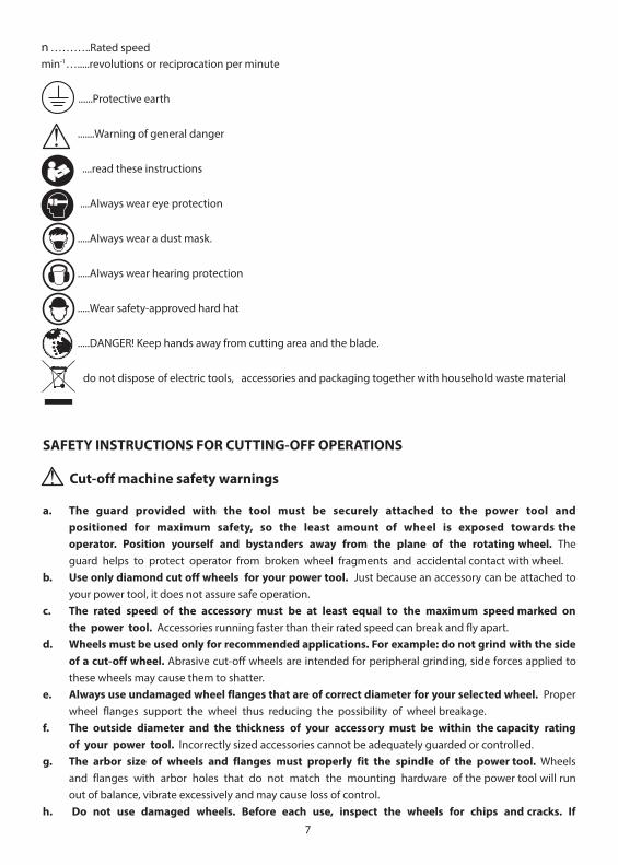
n ………..Rated speedmin-1….....revolutions or reciprocation per minute
......Protective earth
.......Warning of general danger
....read these instructions
....Always wear eye protection
.....Always wear a dust mask.
.....Always wear hearing protection
.....Wear safety-approved hard hat
.....DANGER! Keep hands away from cutting area and the blade.
do not dispose of electric tools, accessories and packaging together with household waste material
8
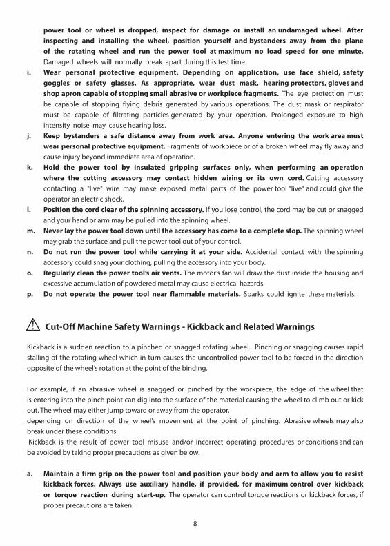
power tool or wheel is dropped, inspect for damage or install an undamaged wheel. After inspecting and installing the wheel, position yourself and bystanders away from the plane of the rotating wheel and run the power tool at maximum no load speed for one minute. Damaged wheels will normally break apart during this test time.
i. Wear personal protective equipment. Depending on application, use face shield, safetygoggles or safety glasses. As appropriate, wear dust mask, hearing protectors, gloves and shop apron capable of stopping small abrasive or workpiece fragments. The eye protection must be capable of stopping flying debris generated by various operations. The dust mask or respirator must be capable of filtrating particles generated by your operation. Prolonged exposure to high intensity noise may cause hearing loss.
j. Keep bystanders a safe distance away from work area. Anyone entering the work area must wear personal protective equipment. Fragments of workpiece or of a broken wheel may fly away and cause injury beyond immediate area of operation.
k. Hold the power tool by insulated gripping surfaces only, when performing an operationwhere the cutting accessory may contact hidden wiring or its own cord. Cutting accessorycontacting a "live" wire may make exposed metal parts of the power tool "live" and could give the operator an electric shock.
l. Position the cord clear of the spinning accessory. If you lose control, the cord may be cut or snagged and your hand or arm may be pulled into the spinning wheel.
m. Never lay the power tool down until the accessory has come to a complete stop. The spinning wheel may grab the surface and pull the power tool out of your control.
n. Do not run the power tool while carrying it at your side. Accidental contact with the spinning accessory could snag your clothing, pulling the accessory into your body.
o. Regularly clean the power tool’s air vents. The motor’s fan will draw the dust inside the housing and excessive accumulation of powdered metal may cause electrical hazards.
p. Do not operate the power tool near flammable materials. Sparks could ignite these materials.
Cut-Off Machine Safety Warnings - Kickback and Related Warnings
Kickback is a sudden reaction to a pinched or snagged rotating wheel. Pinching or snagging causes rapid stalling of the rotating wheel which in turn causes the uncontrolled power tool to be forced in the direction opposite of the wheel’s rotation at the point of the binding.
For example, if an abrasive wheel is snagged or pinched by the workpiece, the edge of the wheel that is entering into the pinch point can dig into the surface of the material causing the wheel to climb out or kick out. The wheel may either jump toward or away from the operator, depending on direction of the wheel’s movement at the point of pinching. Abrasive wheels may also break under these conditions. Kickback is the result of power tool misuse and/or incorrect operating procedures or conditions and can be avoided by taking proper precautions as given below.
a. Maintain a firm grip on the power tool and position your body and arm to allow you to resist kickback forces. Always use auxiliary handle, if provided, for maximum control over kickback or torque reaction during start-up. The operator can control torque reactions or kickback forces, if proper precautions are taken.
9
b. Never place your hand near the rotating accessory. Accessory may kickback over your hand. c. Do not position your body in line with the rotating wheel. Kickback will propel the tool in direction
opposite to the wheel’s movement at the point of snagging. d. Use special care when working corners, sharp edges etc. Avoid bouncing and snagging the
accessory. Corners, sharp edges or bouncing have a tendency to snag the rotating accessory and cause loss of control or kickback.
e. Do not attach a saw chain, woodcarving blade, segmented diamond wheel with a peripheral gap greater than 10 mm or toothed saw blade. Such blades create frequent kickback and loss of control.
f. Do not “jam” the wheel or apply excessive pressure. Do not attempt to make an excessive depth of cut. Overstressing the wheel increases the loading and susceptibility to twisting or binding of the wheel in the cut and the possibility of kickback or wheel breakage.
g. When wheel is binding or when interrupting a cut for any reason, switch off the power tool and hold the power tool motionless until the wheel comes to a complete stop. Never attempt to remove the wheel from the cut while the wheel is in motion otherwise kickback may occur.Investigate and take corrective action to eliminate the cause of wheel binding.
h. Do not restart the cutting operation in the workpiece. Let the wheel reach full speed and carefully re-enter the cut. The wheel may bind, walk up or kickback if the power tool is restarted in the workpiece.
i. Support panels or any oversized workpiece to minimize the risk of wheel pinching and kickback. Large workpieces tend to sag under their own weight. Supports must be placed under the workpiece near the line of cut and near the edge of the workpiece on both sides of the wheel.
j. Use extra caution when making a “pocket cut” into existing walls or other blind areas. The protruding wheel may cut gas or water pipes, electrical wiring or objects that can cause kickback.
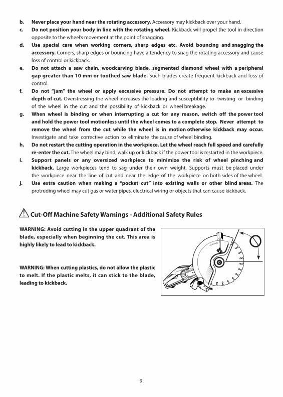
Cut-Off Machine Safety Warnings - Additional Safety Rules
WARNING: Avoid cutting in the upper quadrant of the blade, especially when beginning the cut. This area is highly likely to lead to kickback.
WARNING: When cutting plastics, do not allow the plastic to melt. If the plastic melts, it can stick to the blade, leading to kickback.
10
GROUNDING INSTRUCTIONS
1. All grounded, cord-connected tools:In the event of a malfunction or breakdown, grounding provides a path of least resistance for electric current to reduce the risk of electric shock. This tool is equipped with an electric cord having an equipment-grounding conductor and a grounding plug. The plug must be plugged into a matching outlet that is properly installed and grounded in accordance with all local codes and ordinances. Do not modify the plug provided - if it will not fit the outlet, have the proper outlet installed by a qualified electrician. Improper connection of the equipment-grounding conductor can result in a risk of electric shock. The conductor with insulation having an outer surface that is green with or without yellow stripes is theequipment-grounding conductor. If repair or replacement of the electric cord or plug is necessary, do not connect the equipment-grounding conductor to a live terminal. Check with a qualified electrician or service personnel if the grounding instructions are not completely understood, or if in doubt as to whether the tool is properly grounded. Use only 3-wire extension cords that have 3-prong grounding plugs and 3 pole receptacles that accept the tool's plug. Repair or replace damaged or worn cord immediately.
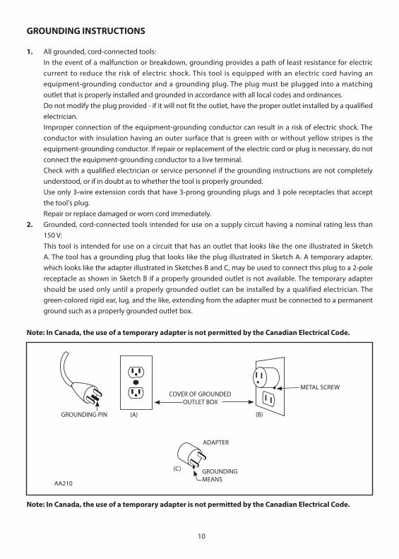
2. Grounded, cord-connected tools intended for use on a supply circuit having a nominal rating less than 150 V:This tool is intended for use on a circuit that has an outlet that looks like the one illustrated in SketchA. The tool has a grounding plug that looks like the plug illustrated in Sketch A. A temporary adapter, which looks like the adapter illustrated in Sketches B and C, may be used to connect this plug to a 2-pole receptacle as shown in Sketch B if a properly grounded outlet is not available. The temporary adaptershould be used only until a properly grounded outlet can be installed by a qualified electrician. The green-colored rigid ear, lug, and the like, extending from the adapter must be connected to a permanent ground such as a properly grounded outlet box.
Note: In Canada, the use of a temporary adapter is not permitted by the Canadian Electrical Code.
Note: In Canada, the use of a temporary adapter is not permitted by the Canadian Electrical Code.
GROUNDING PIN (A)
ADAPTER
GROUNDING MEANS
(C)
AA210
(B)
METAL SCREWCOVER OF GROUNDED OUTLET BOX
11
ELECTRICAL CONNECTION
The network voltage must conform to the voltage indicated on the tool name plate. Under no circumstances should the tool be used when the power supply cable is damaged. A damaged cable must be replaced immediately by an authorized Customer Service Center. Do not try to repair the damaged cable yourself. The use of damaged power cables can lead to an electric shock.
WARNING: Never operate a damaged machine. Always tag a damaged machine and take it out of service until repairs can be made.
WARNING: Always use a Residual Current Device (RCD) also known as a Ground Fault Circuit Interrupter (GFCI) (Not Included). Use an RCD in a separate control box with one or more socket outlets in accordance with EN 60309-2 with the earthing contact position 1 h. Always use this device whenever using the machine to reduce the risk of shock hazards. Test and reset the device before each use.
INTRODUCTION
This machine is equipped with two handles and a blade guard. The motor has overload and overheat protection. It has an integrated water feed system as required for diamond cutting It is used primarily with diamond blades, but abrasive wheels may also be used with this machine. It is intended for cutting masonry, stone, concrete, reinforced concrete and similar materials. All other uses are prohibited.
LIST OF CONTENTS
• Concrete Saw• Guide Roller Assembly• M17 Combination Wrench• Splash Guard
ASSEMBLY
• Mount the blade. ( See below “Mounting the Blade”)• Mount the Guide Roller Assembly if desired ( See below “Guide Roller Assembly”) • Mount the blade guard brush (See below "Blade Guard Brush" for assembly instructions)• Mount the splash guard (See below "Splash Guard" for assembly instructions)
DIAMOND BLADES
Allowed Types Of Blades
This machine may only use diamond blades or abrasive wheels.• Only use either segmented or continuous rim diamond blades.• If the diamond blades are segmented, the maximum allowable peripheral gap between segments is
10mm and must be with a negative rake angle. • Only diamond blades or abrasive wheels of 405mm (16") or less may be used.
12
• Blade thickness must be at least 2.0mm and no greater than 6.35mm
Blade Storage And Transport
Do not store or transport the machine with the blade mounted. Remove the blade and store in such a way that it is protected from being bent or damaged when the machine is not in use-this will help prevent damage to the blade.A damaged blade can cause irregular conditions, this can cause imbalance and result in a hazard.Always inspect new blades for storage or transport damage.
About Diamond Blades
Diamond blades consist of a steel core with diamond segments added to its periphery. Diamond blades are available for different hardnesses of masonry materials, stone, concrete, reinforced concrete, etc. Some diamond blades are designed to be used wet only, while others are designed to be allowed to be used dry. Refer to the blade manufacturer’s instructions.Generally speaking, even if the blade is specified as a dry type blade, diamond tools always work better when wet, and dry cutting should be limited to situations in which water cannot or should not be used. Water will prevent the blade from overheating, greatly reduce the amount of harmful dust created by cutting, remove the slurry from the cut, and extend the life of the blade. Diamond is the hardest substance known, but even diamond is unable to withstand extreme overheating combined with the cutting forces involved. Dry cutting of very hard materials such as porcelain or reinforced concrete will lead to rapid tool wear and possible failure.The diamond impregnated segments in a sintered diamond blade operate on a principle of controlled erosion. The blade does not cut the material, rather it grinds it away. The bond matrix holding the diamonds is continually worn away by abrasion with the workpiece, exposing the harder diamonds to stand proud from the bond matrix. A blade with good diamond exposure is a sharp blade. Blades made for cutting harder materials will have a softer bond, allowing the diamonds project more aggressively (but will not last as long). Blades made for cutting softer, abrasive materials will have a harder bond, allowing them to resist the abrasiveness of the material and to last longer. The other factor is the grit size of the diamonds themselves: very hard materials tend to require a finer grit size, while coarser grits will cut faster. This erosion process causes heat and particles, which require water to cool and rinse free. Without adequate water, the blade would overheat and be destroyed.With too much water and not enough feed pressure, there would not be adequate erosion of the bond matrix (the diamonds not exposed) and the blade becomes dull (diamond segments polish smooth). This is called glazing and luckily the blade can be de-glazed (sharpened). If the blade seems to refuse to cut anymore, you know that it is glazed. See below: ”Sharpening a Glazed Blade”Never use a sharp motion or the blade will be damaged. Conversely, don’t feed too gently or the diamond segments will become glazed. Keep the blade steadily working, but don’t be abusive or give the blade shock impacts into the work surface.Take great care to keep the blade perpendicularly aligned to the kerf. If the blade is crooked, it will easily bind. When cutting reinforced concrete, if embedded steel such as rebar is encountered, take special care. When the steel is encountered, the water will generally go clear and vibration will begin. Reduce the feed pressure by about 1/3 and let the blade go at its own pace, if there is too much vibration the blade may be destroyed. Once
13
the steel is passed, continue normally. A properly sharp blade with good diamond exposure should be able to cut through rebar if handled well.
NOTE: Never use a wet-type diamond blade without water. It will overheat and be destroyed.
NOTE: When using dry blades, do not allow them to overheat. It is best to cut no longer than about 60 seconds at a time, with 10 second running in air cool down times in between.
Always mount the blade with the arrow matching the direction of rotation of the machine (A direction arrow is marked on the blade guard).
WARNING: Never use blades for cutting a material other than the material they were intended for.
SHARPENING A GLAZED BLADE
Diamond blades may become glazed (dull) for various reasons, such as cutting reinforced concrete with an excess of embedded steel, or from cutting with too little downforce which can lead to the segments becoming polished or “glazed”. Once the diamond segments are glazed, the blade’s cutting performance will degrade and the segments will overheat. To resharpen the blade, turn down the water feed and make a few cuts in a very soft, abrasive material such as brick.
MOUNTING THE BLADE
First make sure that the machine is unplugged. Then, using the 17mm combination wrench, engage the arbor bolt and turn the arbor while pressing on the arbor lock (See page 2). When the arbor reaches the right position, the arbor lock will be allowed to engage. Then the arbor bolt may be loosened and the plain outer flange may be removed. (It is a standard, right hand thread, so turn anticlockwise to loosen.)The inner flanges are specific to the blade arbor bore diameter. There are three possible blade arbor bore sizes depending on the market where the machine is sold: 20mm, 22.2mm (7/8”), and 25.4mm (1”) Check the inner flange to ensure that the size matches the bore of the blade which you intend to use. The 7/8” and 1” sizes each have a specific inner flange which must be used. For the 20mm size, the bore directly engages the arbor and thus uses a plain flange on both the inside and outside.
Inspect the blade before use. It must not be cracked, warped or damaged in any way that would cause a hazard in operation. Loose diamond segments can be ejected at high speed, causing possible injury. Always check that the diamond segments are not under cut. If the diamond segments are thinner or nearly thinner than the blade core, the kerf will be too tight fitting and could easily lead to kickback.
Ensure that the flanges and blade bore are clean and undamaged and that everything fits properly. The flanges may not be used if they are warped, the surface is uneven, burred or if they are dirty. The arbor bolt and arbor threads must be undamaged. Inspect the blades for segment damage, arbor hole damage or any other damage which could cause hazardous operation. The protruding edge of the inner flange should be facing the blade. Then mount the blade to the inner flange and add the outer flange. Add the arbor bolt and tighten to 15-25 Nm.
14
WARNING: Do not attempt to mount a blade which does not match the mounting hardware. It will lead to eccentric running and vibration which will be uncontrollable.
ADJUSTING THE BLADE GUARD
The blade rotates clockwise when viewed from the arbor end. Therefore, most of the cutting debris, sparks and slurry is thrown to the rear. So the blade guard should be adjusted so that the rear edge is flush with the workpiece.
TO ADJUST
First pull out the locking lever against the spring tension, then rotate the blade guard to the desired position. Allow the locking lever to engage the nearest slot in the guard to lock it into position.
BLADE GUARD BRUSH
There is a removable brush at the rear of the guard to help contain sparks, dust, debris and slurry. To install, simply push the brush into the slot in the bottom of the dust port bracket until it clicks in place. This brush may be pulled straight out to replace when worn.
SPLASH GUARD
The spring-loaded splash guard is useful to help to contain slurry which splashes toward the back. To install, simply clip into place on the back of the dust port bracket. To remove, tilt upward to pop free.If the splash guard is not needed, such as when cutting dry, it may be clipped up out of the way. Simply engage the male clip on the flap with the female clip on the mount. Unclip to release.
WATER CONNECTION
Water is a basic requirement for diamond sawing with wet-type diamond blades. The water serves as a coolant to avoid the working surface of the diamond segments from overheating. When the diamond bit becomes overheated, both the bond matrix and even the diamonds break down, thus destroying the blade. Besides cooling, water also keeps down dust and flushes away abrasive particles.
WARNING: Always use a PRCD (GFCI) (not included) when operating with waterWARNING: Never allow water to enter the motor. It could lead to an electric shock.
WARNING: Check all connections of the water feed system to ensure there are no leaks. Inspect hoses and other critical parts which could deteriorate.
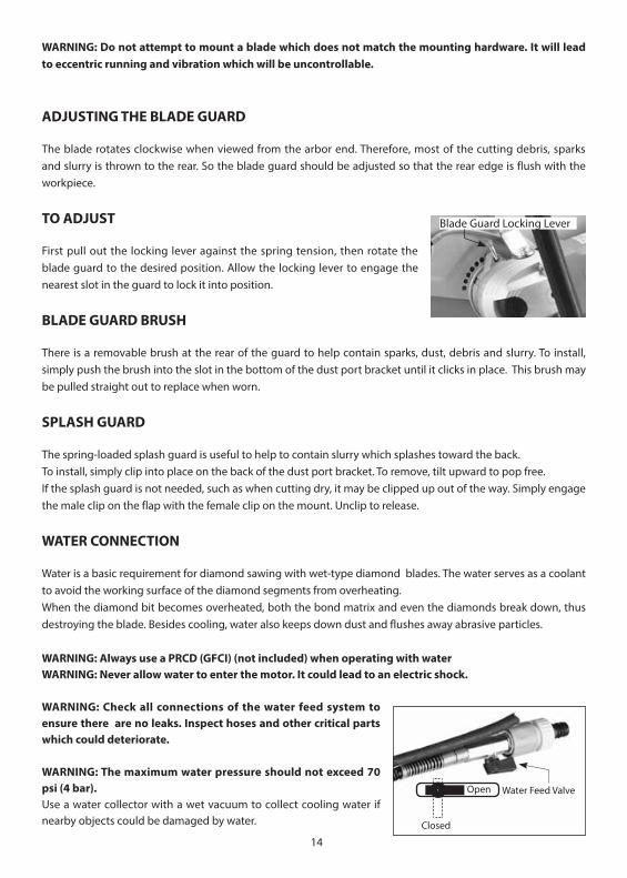
WARNING: The maximum water pressure should not exceed 70 psi (4 bar).Use a water collector with a wet vacuum to collect cooling water if nearby objects could be damaged by water.
Open
Closed
Water Feed Valve
Blade Guard Locking Lever
15
The water feed system is built into the machine. To connect with the water supply, first pull the quick-release collar to remove the female side of the water coupling. Then unscrew the nut and engage the coupling to the water hose. Now reconnect the water coupling to the male water feed valve. Press it until it clicks.The water flow is controlled by the water feed valve. The water to the blade may be finely adjusted to the required amount and no more.
NOTE: Contaminants in the water supply can easily plug up the fine water nozzles in the blade guard. Ensure that the supply water is clean. If you find that there is no water flow to the blade, then clean out the water feed system on the machine.
GUIDE ROLLER ASSEMBLY
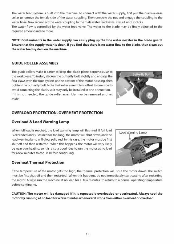
The guide rollers make it easier to keep the blade plane perpendicular to the workpiece. To install, slacken the butterfly bolt slightly and engage the four claws with the four eyelets on the bottom of the motor housing, then tighten the butterfly bolt. Note that roller assembly is offset to one side to avoid contacting the blade, so it may only be installed in one orientation.If it is not needed, the guide roller assembly may be removed and set aside.
OVERLOAD PROTECTION, OVERHEAT PROTECTION
Overload & Load Warning Lamp
When full load is reached, the load warning lamp will flash red. If full load is exceeded and sustained for too long, the motor will shut down and the load warning lamp will glow solid red. In this case, the motor must be first shut off and then restarted. When this happens, the motor will very likely be near overheating, so it is also a good idea to run the motor at no load for a few minutes to cool it before continuing.
Overheat Thermal Protection
If the temperature of the motor gets too high, the thermal protection will shut the motor down. The switch must be first shut off and then restarted. When this happens, do not immediately start cutting after restarting the motor. Always run the machine at no load for a few minutes to return to a normal operating temperature before continuing.
CAUTION: The motor will be damaged if it is repeatedly overloaded or overheated. Always cool the motor by running at no load for a few minutes whenever it stops from either overheat or overload.
Butterfly Bolt
Load Warning Lamp
16
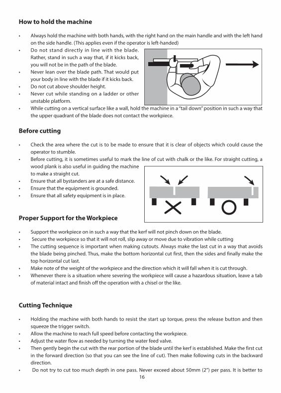
How to hold the machine
• Always hold the machine with both hands, with the right hand on the main handle and with the left hand on the side handle. (This applies even if the operator is left-handed)
• Do not stand directly in line with the blade.Rather, stand in such a way that, if it kicks back, you will not be in the path of the blade.
• Never lean over the blade path. That would putyour body in line with the blade if it kicks back.
• Do not cut above shoulder height.• Never cut while standing on a ladder or other
unstable platform. • While cutting on a vertical surface like a wall, hold the machine in a “tail down” position in such a way that
the upper quadrant of the blade does not contact the workpiece.
Before cutting
• Check the area where the cut is to be made to ensure that it is clear of objects which could cause the operator to stumble.
• Before cutting, it is sometimes useful to mark the line of cut with chalk or the like. For straight cutting, a wood plank is also useful in guiding the machine to make a straight cut.
• Ensure that all bystanders are at a safe distance.• Ensure that the equipment is grounded.• Ensure that all safety equipment is in place.
Proper Support for the Workpiece
• Support the workpiece on in such a way that the kerf will not pinch down on the blade. • Secure the workpiece so that it will not roll, slip away or move due to vibration while cutting• The cutting sequence is important when making cutouts. Always make the last cut in a way that avoids
the blade being pinched. Thus, make the bottom horizontal cut first, then the sides and finally make the top horizontal cut last.
• Make note of the weight of the workpiece and the direction which it will fall when it is cut through.• Whenever there is a situation where severing the workpiece will cause a hazardous situation, leave a tab
of material intact and finish off the operation with a chisel or the like.
Cutting Technique
• Holding the machine with both hands to resist the start up torque, press the release button and thensqueeze the trigger switch.
• Allow the machine to reach full speed before contacting the workpiece. • Adjust the water flow as needed by turning the water feed valve. • Then gently begin the cut with the rear portion of the blade until the kerf is established. Make the first cut
in the forward direction (so that you can see the line of cut). Then make following cuts in the backwarddirection.
• Do not try to cut too much depth in one pass. Never exceed about 50mm (2”) per pass. It is better to
17
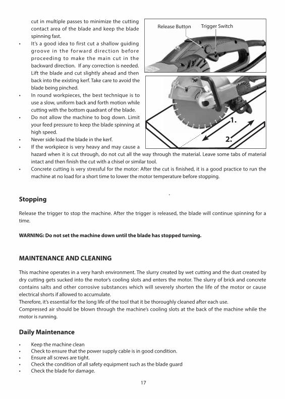
cut in multiple passes to minimize the cutting contact area of the blade and keep the blade spinning fast.
• It’s a good idea to first cut a shallow guiding groove in the for ward di rec t ion beforeproceeding to make the main cut in thebackward direction. If any correction is needed. Lift the blade and cut slightly ahead and then back into the existing kerf. Take care to avoid the blade being pinched.
• In round workpieces, the best technique is to use a slow, uniform back and forth motion while cutting with the bottom quadrant of the blade.
• Do not allow the machine to bog down. Limit your feed pressure to keep the blade spinning at high speed.
• Never side load the blade in the kerf.• If the workpiece is very heavy and may cause a
hazard when it is cut through, do not cut all the way through the material. Leave some tabs of materialintact and then finish the cut with a chisel or similar tool.
• Concrete cutting is very stressful for the motor: After the cut is finished, it is a good practice to run themachine at no load for a short time to lower the motor temperature before stopping.
Stopping
Release the trigger to stop the machine. After the trigger is released, the blade will continue spinning for a time.
WARNING: Do not set the machine down until the blade has stopped turning.
MAINTENANCE AND CLEANING
This machine operates in a very harsh environment. The slurry created by wet cutting and the dust created by dry cutting gets sucked into the motor’s cooling slots and enters the motor. The slurry of brick and concrete contains salts and other corrosive substances which will severely shorten the life of the motor or cause electrical shorts if allowed to accumulate.Therefore, it’s essential for the long life of the tool that it be thoroughly cleaned after each use. Compressed air should be blown through the machine’s cooling slots at the back of the machine while the motor is running.
Daily Maintenance
• Keep the machine clean• Check to ensure that the power supply cable is in good condition.• Ensure all screws are tight.• Check the condition of all safety equipment such as the blade guard• Check the blade for damage.
Release Button Trigger Switch
1.
2.

18
Carbon Brushes
The carbon brushes are a normal wearing part and must be replaced when they reach their wear limit. This machine is equipped with auto-stop carbon brushes. If the machine comes to a stop unexpectedly, the brushes should be checked. The auto-stop brush design protects the motor by stopping the machine before the carbon brushes are completely worn out.
Caution: Always replace the brushes as a pair.
To replace
1. Remove the screw and remove the brush cover. 2. Using pliers rotate the brush spring out of the way and slide the old carbon brush out of the brush
holder.3. Unscrew the screw to remove the brush lead. The old carbon brush may now be lifted away.4. Install a new brush. Installation is the reverse of removal.5. Replace the brush cover.
If the replacement of the power supply cord is necessary, this has to be done by the manufacturer or their agent in order to avoid a safety hazard.
WARNING: All repairs must be entrusted to an authorized service center. Incorrectly performed repairs could lead to injury or death.
Do not throw electric power tools into the household waste!In accordance with the European Directive 2002/96/EG on Waste Electrical and Electronic Equipment and transposition into national law, used electric power tools must be collected separately and recycled in an environmentally friendly manner.
Brush Cover
19
FLUSH CUTTING KIT INSTRUCTIONS
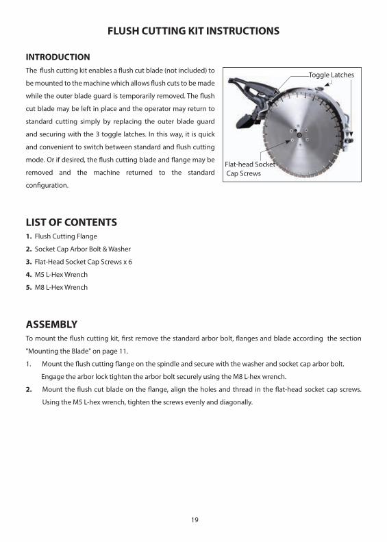
INTRODUCTIONThe flush cutting kit enables a flush cut blade (not included) to
be mounted to the machine which allows flush cuts to be made
while the outer blade guard is temporarily removed. The flush
cut blade may be left in place and the operator may return to
standard cutting simply by replacing the outer blade guard
and securing with the 3 toggle latches. In this way, it is quick
and convenient to switch between standard and flush cutting
mode. Or if desired, the flush cutting blade and flange may be
removed and the machine returned to the standard
configuration.
LIST OF CONTENTS1. Flush Cutting Flange
2. Socket Cap Arbor Bolt & Washer
3. Flat-Head Socket Cap Screws x 6
4. M5 L-Hex Wrench
5. M8 L-Hex Wrench
ASSEMBLYTo mount the flush cutting kit, first remove the standard arbor bolt, flanges and blade according the section
"Mounting the Blade" on page 11.
1. Mount the flush cutting flange on the spindle and secure with the washer and socket cap arbor bolt.
Engage the arbor lock tighten the arbor bolt securely using the M8 L-hex wrench.
2. Mount the flush cut blade on the flange, align the holes and thread in the flat-head socket cap screws.
Using the M5 L-hex wrench, tighten the screws evenly and diagonally.
Toggle Latches
Flat-head Socket Cap Screws
20
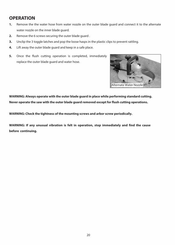
5. Once the flush cutting operation is completed, immediately
replace the outer blade guard and water hose.
WARNING: Always operate with the outer blade guard in place while performing standard cutting.
Never operate the saw with the outer blade guard removed except for flush cutting operations.
WARNING: Check the tightness of the mounting screws and arbor screw periodically.
WARNING: If any unusual vibration is felt in operation, stop immediately and find the cause
before continuing.
Alternate Water Nozzle
OPERATION1. Remove the the water hose from water nozzle on the outer blade guard and connect it to the alternate
water nozzle on the inner blade guard.
2. Remove the 6 screws securing the outer blade guard .
3. Unclip the 3 toggle latches and pop the loose hasps in the plastic clips to prevent rattling.
4. Lift away the outer blade guard and keep in a safe place.
21
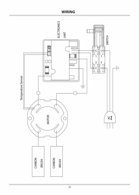
WIRING
CARB
ON
BRU
SH
CARB
ON
BRU
SH
MO
TOR
ACSW
ITCH
1
2
1
2EL
ECTR
ON
ICS
UN
IT
Tem
pera
ture
Sen
sor
22
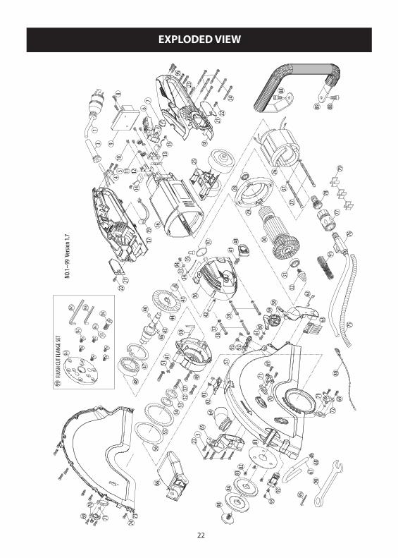
EXPLODED VIEW
235
1011 12
14
1598
6
23
96
24
2122
2122
54
16
18
17 30
29
28
3132
27
26
3
7
13
5859
6061
63
6465
6768
69
6971
72
81
8283
84
69 71
7576
77
78
7980
7473
90
88
88
89
62
9433
34
36
42
38
4041
4645
44
43
48
37
4746
49
5354
55
50
4151
5237
56
39
7170
70
25
6619
91
57
9392
9392
93 92
NO.
1~99
Ver
sion 1
.7
37
95
1
35
97
98
99-1
99-2
99-399-4
99-5 99-6
FLUS
H CU
T FLA
NGE S
ET99

DP PART # DESCRIPTION1 2709077 POWER CABLE (UL-12Ax3Cx3.5M-SJTW)(115V)
2709104 POWER CABLE (UL-14Ax3Cx3.5M-SJTW)(230V)3 6078600 CORD ARMOR 115V
6078619 CORD ARMOR 230V4 6078404 CABLE CLIP5 6078405 PANHEAD TAPPING SCREW M4 x 146 6078406 SWITCH LOCK-OFF7 6078407 SWITCH BUTTON8 6078601 PANHEAD TAPPING SCREW M4 x 169 6078602 ELECTRONICS UNIT 115V
6078620 ELECTRONICS UNIT 230V10 6078410 PANHEAD TAPPING SCREW M4 x 811 6078411 BRUSH SPRING12 6078412 CARBON BRUSH HOLDER13 6078413 INSULATION PLATE14 6078414 CARBON BRUSH 7 x 17 x 19 (115V)
6078621 CARBON BRUSH 7 x 17 x 19 (230V)15 6078415 PANHEAD MACHINE SCREW M4 x 616 6078416 MOTOR HOUSING17 6078417 HANDLE HALF-RIGHT18 6078418 HANDLE HALF-LEFT19 6078485 LED INDICATOR LIGHT21 6078420 CARBON CAP22 6078421 PANHEAD TAPPING SCREW M4 x 1223 6078422 PANHEAD TAPPING SCREW M4 x 2524 6078423 PANHEAD TAPPING SCREW M4 x 5025 6078424 GUIDE ROLLER ASSY.26 6078603 STATOR (115V)
6078622 STATOR (220V)27 6078604 PANHEAD TAPPING SCREW M5 x 9028 6078427 BALL BEARING 6200LLU29 6078605 FAN SHROUD30 6078606 ARMATURE (115V)
6078623 ARMATURE (230V)31 6078430 BALL BEARING 6202-2NSE32 6078431 BEVEL PINION GEAR M2.35 x 6T33 6078432 EXTERNAL STAR WASHER M434 6078433 WIRE LEAD 20AWG x 35CM35 6078607 CRIMP CAP CONNECTOR C5

DP PART # DESCRIPTION36 6078435 GEAR HOUSING37 6078436 SPRING WASHER M538 6078608 PANHEAD TAPPING SCREW M5 x 4539 6078609 PANHEAD TAPPING SCREW M5 x 5040 6078438 SPINDLE LOCK BUTTON41 6078439 SPRING Ø0.9 x Ø7.4 x Ø9.2 x 5T x 16L42 6078440 ARBOR LOCK43 6078441 NEEDLE BEARING TA 121244 6078442 BEVEL GEAR M2.35 x 37T45 6078444 SPINDLE46 6078445 PARALLEL KEY 5 x 5 x 1047 6078446 INTERNAL CIRCLIP R-6248 6078447 BALL BEARING 6206-ZZ49 6078448 GEAR PLATE50 6078449 L-CLEVIS PIN51 6078450 E-CLIP E-552 6078451 SOCKET CAP SCREW M5 x 2053 6078452 OIL SEAL Ø25 x Ø35 x 554 6078453 FELT OILER Ø25 x Ø35 x 2.555 6078454 RUBBER FENDER Ø75 x Ø91 x 4 (EP 50)56 6078489 PLASTIC RING Ø74 x Ø91.5 x 0.25(MM)57 6078610 UPPER BLADE COVER58 6078456 DUST PORT BRACKET-LEFT59 6078457 DUST PORT PLUG EP 5.5G60 6078458 FLAT WASHER Ø4 x Ø10 x 161 6078459 PANHEAD TAPPING SCREW M4 x 1062 6078488 CLIP-FEMALE63 6078461 BLADE GUARD BRUSH64 6078460 DUST ATTACHMENT65 6078462 DUST PORT BRACKET-RIGHT66 6078486 SPLASH GUARD67 6078465 TUBE 0.2M68 6078487 WIRE HOSE CLAMP69 6078466 FLAT HEAD TAPPING SCREW M4 x 1670 6078468 WATER NOZZLE ASSY.-R71 6078611 O-RING Ø4 x 1.572 6078467 WATER NOZZLE ASSY.-L73 6078612 OUTER BLADE COVER74 6078613 SOCKET CAP SCREW M4 x 12

DP PART # DESCRIPTION75 6078469 CABLE PROTECTOR 5/16" x 75CM76 6078614 WATER FEED CONNECTOR KIT77 6078471 WATER COUPLING78 6078472 FITTING79 6078483 HOSE JOINER80 6078484 ZIP TIE KTV-150BK81 6078473 RETAINING PLATE Ø25.1 x Ø90 x 1.582 6078474 FLAT HEAD MACHINE SCREW M5 x 883 6078475 INNER FLANGE Ø25.484 6078476 COUNTER FLANGE88 6078480 SOCKET CAP SCREW M8 x 1689 6078481 FRONT HANDLE90 6078482 COMBINATION WRENCH M1791 6078491 SPRING92 6078615 TOGGLE LATCH93 6078616 PANHEAD MACHINE SCREW M4 x 694 6078492 TRUSS HEAD MACHINE SCREW M4 x 695 6078617 SOCKET HEX KEY M396 6078490 PANHEAD TAPPING SCREW M4 x 2097 6078497 O-RING Ø35 x 1.5(NBR)98 6078498 BOLT M10 x P1.599 6078618 FLUSH CUT FLANGE SET
99-1 6078718 FLANGE99-2 2902255 FLAT HEAD SOCKET CAP SCREW M8 x 1699-3 FLAT WASHER99-4 SOCKET CAP SCREW M10 x 2599-5 6078719 SOCKET HEX KEY M899-6 6078720 SOCKET HEX KEY M5

NOTES ____________________________________________________________________________________________________________________________________________________________________________________________________________________________________________________________________________________________________________________________________________________________________________________________________________________________________________________________________________________________________________________________________________________________________________________________________________________________________________________________________________________________________________________________________________________________________________________________________________________________________________________________________________________________________________________________________________________________________________________________________________________________________________________________________________________________________________________________________________________________________________________________________________________________________________________________________________________________________________________________________________________________________________________________________________________________________________________________________________________________________________________________________________________________________

NOTES ____________________________________________________________________________________________________________________________________________________________________________________________________________________________________________________________________________________________________________________________________________________________________________________________________________________________________________________________________________________________________________________________________________________________________________________________________________________________________________________________________________________________________________________________________________________________________________________________________________________________________________________________________________________________________________________________________________________________________________________________________________________________________________________________________________________________________________________________________________________________________________________________________________________________________________________________________________________________________________________________________________________________________________________________________________________________________________________________________________________________________________________________________________________________________

333 Prospect Street, Elyria, Ohio 44035(440) 323-4616 (800) 321-5336 Fax (440) 323-8689
www.diamondproducts.comPrinted in U.S.A. #XXXXXXX
EQUIPMENT AND PARTSWARRANTY
Diamond Products warrants all equipment manufactured by it against defectsin workmanship or materials for a period of one (1) year from the date ofshipment to Customer.
The responsibility of Diamond Products under this Warranty is limited toreplacement or repair of defective parts at Diamond Products’ Elyria, Ohiofactory, or at a point designated by it, of such parts as shall appear to us uponinspection at such parts, to have been defective in material or workmanship,with expense for transportation and labor borne by Customer.
In no event shall Diamond Products be liable for consequential orincidental damages arising out of the failure of any Product to operate properly.
Integral units such as engines, electric motors, batteries, transmissions,etc., are excluded from this Warranty and are subject to the primemanufacturer’s warranty.
THIS WARRANTY IS IN LIEU OF ALL OTHER WARRANTIES, EXPRESSEDOR IMPLIED, AND ALL SUCH OTHER WARRANTIES ARE HEREBYDISCLAIMED.