Embed Size (px)
Citation preview

VC-50 Instruction Manual
VC-50Precision
Diamond Saw
U.S. Patent 3935677Other patents are pending inthe U.S.A. and other countries.
Minor revisions may not be reflectedin this manual.
©2001 LECO® Corporation
Part Number 200-019
November 2001

2 VC-50 Instruction Manual
This page intentionally left blank.

Instruction Manual VC-50 3
Table of Contents
Table of Contents ..................................................................... 3
Illustrations List........................................................................ 4
Warranty................................................................................. 5
Notice........................................................................... 6
Caution ......................................................................... 6
Warning and Caution Symbols..................................................... 7
Interference to Other Devices ..................................................... 8
Declaration of Conformity........................................................... 9
Major Equipment and Accessories List .........................................11
Options ..................................................................................12
Service Parts.................................................................12
Components and Accessories List ...............................................13
Specifications..........................................................................15
Installation .............................................................................17
Operation...............................................................................23
Setting Automatic Shut-Off .......................................................26
Wafer Cutting..........................................................................27
Diamond Wheel Dressing ..........................................................28
Relationship Between RPM And Feet/Minute..................................29
Guidelines for Sectioning Various Materials ...................................30
Guideline Reference Table ...............................................31
Schematics.............................................................................35
Index.....................................................................................41
4 VC-50 Instruction Manual
Illustrations List
Figure 1 ............ VC-50 Precision Diamond Saw......................10
Figure 2 ............ VC-50 Front View.......................................20
Figure 3 ............ VC-50 Rear View .......................................21
Figure 4 ............ Cutting Area—Front View ............................22
Figure 5 ............ Cutting Area—Side View..............................22
Figure 6 ............ Irregular Specimen Holder...........................25
Figure 7 ............ Slide Holder..............................................25
Figure 8 ............ VC-50 Upper Section—Exploded View ............33
Figure 9 ............ VC-50 Base and Lower Section—Exploded View ........................................34
Figure 10........... 150-741 Cabinet Schematic .........................36
Figure 11........... 806-398 Speed Controller ...........................37
Figure 12........... 777-858 Relay/Transformer Card..................38
Figure 13........... 777-858-011 Relay/TransformerCard Schematic .........................................39

Instruction Manual VC-50 5
Warranty
Equipment manufactured by LECO Corporation, St. Joseph,Michigan is warranted free from defect in material andworkmanship for a period of six months from the date ofinstallation. Equipment not manufactured by LECO is covered tothe extent of warranty provided by the original manufacturerand this warranty does not cover any equipment, new or used,purchased from anyone other than LECO Corporation. Allreplacement parts shall be covered under warranty for a periodof thirty days from date of purchase. LECO makes no otherrepresentation or warranty of any other kind, expressedor implied, with respect to the goods sold hereunder,whether as to merchantability, fitness for purpose, orotherwise.
Expendable items such as crucibles, combustion tubes,chemicals, and items of like nature are not covered by thiswarranty.
LECO's sole obligation under this warranty shall be to repair orreplace any part or parts which, to our satisfaction, prove to bedefective upon return prepaid to LECO Corporation, St. Joseph,Michigan. This obligation does not include labor to installreplacement parts, nor does it cover any failure due toaccident, abuse, neglect, or use in disregard of instructionsfurnished by LECO. In no event shall damages for defectivegoods exceed the purchase price of the goods, and LECO shallnot be liable for incidental or consequential damageswhatsoever.
All claims in regard to the parts or equipment must be madewithin ten (10) days after Purchaser learns of the facts uponwhich the claim is based. Authorization must be obtained fromLECO prior to returning any other parts. This warranty is voidedby failure to comply with these notice requirements.

6 VC-50 Instruction Manual
Notice
The warranty on LECO equipment remains valid only whengenuine LECO replacement parts are employed. Since LECO hasno control over the quality or purity of consumable products notmanufactured by LECO, the specifications for accuracy ofresults using LECO instruments are not guaranteed unlessgenuine LECO consumables are employed in conjunction withLECO instruments. If purchaser defaults in making payment forany parts or equipment, this warranty shall be void and shallnot apply to such parts and equipment. No late payment orcure of default in payment shall extend the warranty periodprovided herein.
LECO Corporation is not responsible for damage to anyassociated instruments, equipment, or apparatus nor will LECObe held liable for loss of profit or other special damagesresulting from abuse, neglect, or use in disregard ofinstructions. The Buyer, their employees, agents, andsuccessors in interest assume all risks and liabilities for theoperation, use, and/or misuse of the product(s) describedherein and agree to indemnify, hold harmless, and defend theseller from any and all claims and actions arising from anycause whatsoever, including seller's negligence for personalinjury incurred in connection with the use of said product(s)and any and all damages proximately resulting therefrom.
CautionThe instrument should be operated only by technically qualifiedindividuals who have fully read and understand theseinstructions. The instrument should be operated only inaccordance with these instructions.
The operator should follow all of the warnings and cautions setforth in the manual and the operator should follow and employall applicable standard laboratory safety procedures.
LECO is a registered trademark of LECO Corporation.Windows is a registered trademark of Microsoft Corporation.Excel is a registered trademark of Microsoft Corporation.Windows 95 is a trademark of Microsoft Corporation.Windows 3.1 is a trademark of Microsoft Corporation.

Instruction Manual VC-50 7
Warning and Caution Symbols
The following symbols may be found on LECO equipment ortheir components. These symbols indicate the use of specificsafety guidelines. Important safety information is highlighted inthis manual by one of the following symbols as well asWARNING and CAUTION statements. Operator and servicepersonnel must follow these instructions for personal safety andto prevent damage to the equipment.
This symbol indicates a risk of electrical shock.Refer to the manual for specific instructions.
This symbol indicates a high temperaturesurface. Refer to the manual for specificinstructions.
This symbol indicates a caution. Refer to themanual for specific instructions.
LECO equipment should be operated only by technicallyqualified individuals who have fully read and understand theinstructions detailed in this manual. The equipment should beoperated only in accordance with these instructions.
The operator should follow all of the warnings and cautions setforth in this manual and the operator should follow and employall applicable standard laboratory safety procedures.
CAUTION
!
WARNING
WARNING

8 VC-50 Instruction Manual
Interference to Other Devices
This equipment has been tested and found to comply with thelimits for a Class A digital device, pursuant to Part 15 of theFCC Rules and Regulations. These limits are designed toprovide reasonable protection against harmful interferencewhen this equipment is operated in a commercial environment.This equipment generates, uses and can radiate radiofrequency energy and, if not installed and used in accordancewith the instructions, may cause interference to radiocommunications. Operation of this equipment in a residentialarea is likely to cause harmful interference in which case theuser will be required to correct the interference at his ownexpense.

Instruction Manual VC-50 9
Declaration of Conformity

10 VC-50 Instruction Manual
Figure 1VC-50 Precision Diamond Saw

Instruction Manual VC-50 11
Major Equipment and Accessories List
The LECO VC-50 is a variable speed diamond saw designed forprecision sectioning of metals, ceramics, electroniccomponents, and geological samples of up to 11/2-inchdiameter.
• Items listed below are repeated throughout this manual aresubject to revision. Please consult the packing slip receivedwith the instrument.
• For a complete listing of kits and packages, refer toComponents and Accessories List, beginning on page 13.
800-900 VC-50 Saw with English Micrometer (115V)
1 800-900-020 VC-50 Saw
1 200-019 Instruction Manual
1 808-908 Component Pack
800-900-200 VC-50 Saw with English Micrometer (230V)
1 800-900-020 VC-50 Saw
1 200-019 Instruction Manual
1 808-907 Component Pack
801-900 VC-50 Saw with Metric Micrometer (115V)
1 800-900-020 VC-50 Saw
1 200-019 Instruction Manual
1 808-908 Component Pack
801-900-200 VC-50 Saw with Metric Micrometer (230V)
1 800-900-020 VC-50 Saw
1 200-019 Instruction Manual
1 808-907 Component Pack
Notes
12 VC-50 Instruction Manual
Options
• For kit contents, refer to Components and Accessories List,beginning on page 13.
801-136 Diamond Wheel (5-inch x 0.014") (1/pkg)
801-137 Diamond Wheel (4-inch x 0.012") (1/pkg)
801-563 Thin Section Slide Ho lder
801-567 Specimen Holder (Irregular Shape)
802-439 Diamond Wheel (5-inch x 0.025") (1/pkg)
807-425 RV-50 Rotating Vise Package
807-956-110 Speed Controller Kit (115V)
807-957-110 Speed Controller Kit (230V)
811-022 Cutting Oil (1 Pint)
811-023 Cutting Oil (1 Quart)
811-024 Cutting Oil (1 Gallon)
811-146 Abrasive Wheel (4-inch x 0.010"/Aluminum Oxide) (10/pkg)
Service Parts190-875 Screw (10-32x0.75)
767-376 Contact
801-040 Motor Control Card Assembly
801-045 Base Motor
801-066 Belt Gear (#150xl037)
801-099 Wheel Coolant
802-318 Ring Retaining Ext (0.75" shaft)
802-344 Flanges (For 4-inch Blades — 2 Required)
804-570-110 Shock Absorber Replacement Kit
Note

Instruction Manual VC-50 13
Components and Accessories List
808-907 Component Pack (230V)
1 760-568 Wrench Allen (0.078 Hex)
1 801-136 Diamond Wheel (5-inch)
1 801-552 Removable Splash Shield
1 801-563 Slide Holder
1 801-567 Specimen Holder (Irregular)
1 801-724 Dressing Stick
1 802-367 Space Spindle Handle
1 803-082 Wheel Dresser
1 803-578 Splash Guard
1 808-906 Power Cord
1 811-023 Cutting Oil (1 Quart)
808-908 Component Pack (115V)
1 760-568 Wrench Allen (0.078 Hex)
1 776-997 Power Cord
1 801-136 Diamond Wheel (5-inch)
1 801-552 Removable Splash Shield
1 801-563 Slide Holder
1 801-567 Specimen Holder (Irregular)
1 801-724 Stick Dressing
1 802-367 Space Spindle Handle
1 803-082 Wheel Dresser
1 803-578 Splash Guard
1 811-023 Cutting Oil (1 Quart)

14 VC-50 Instruction Manual
807-956-110 Speed Controller Kit (115V)
1 776-997 Power Cord
1 807-956-901 Speed Controller Kit Bulletin
1 808-904 Speed Controller
807-957-110 Speed Controller Kit (230V)
1 807-957-901 Speed Controller Kit Bulletin
1 808-905 Speed Controller
1 808-906 Power Cord
Instruction Manual VC-50 15
Specifications
Diamond Wheel Speed
5-inch Wheel (standard)....................50 to 650 sfm
4-inch Wheel (optional) .....................50 to 525 sfm
Spindle Speed ....................................0 to 500 rpm
Drive Motor........................................1/15 HP
Operating Temperature Range............35oF to 110oF (2oC to 43oC)
Electrical Power Requirements ...........115 V~ (±10%), 50/60 Hz,1 phase, 200 watts230 V~ (±10%), 50/60 Hz,1 phase, 200 watts
Dimensions
Height ............................................11.5 inches (29 cm)
Width.............................................13.5 inches (34 cm)
Depth ............................................21.5 inches (55 cm)
Weight ...........................................52 pounds (24 kg)

16 VC-50 Instruction Manual
This page intentionally left blank.

Instruction Manual VC-50 17
Installation
ELECTRICAL SHOCK HAZARDThis equipment operates from either 115V~ or230V~. Contact with this voltage can be lethal.During installation, do not apply power untilinstructed to do so.
Steps
1. Place the VC-50 on a solid and level work surface withconvenient electrical power supply. Refer to Specifications,page 15, for power requirements.
2. Check the speed control for proper operation.
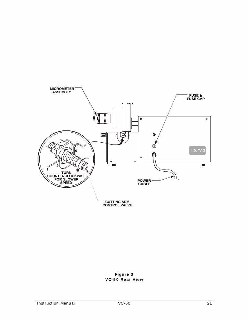
A. Locate the cutting arm control valve on the back ofthe unit and turn the valve counter-clockwise(towards 6) until it comes to a complete stop (figure 3, page 21).
B. Holding on to the vise, raise the cutting arm to its up-most position (figure 5, page 22).
C. Turn the cutting arm locking device clockwise to thelocked position. The cutting arm may drop slightlybut should remain in the raised position (figure 2,page 20).
D. Insert the spindle spacer handle to keep the spindlefrom rotating (figure 4, page 22).
E. Remove the vise locking screw (figure 5, page 22),short spindle spacer, two spindle flanges, and longspindle spacer from the spindle (figure 4, page 22).
F. Check the serial ID tag on the back of the unit for therequired power supply and then connect the unit tothe proper facility power (figure 3, page 21).
G. Turn the power on by pressing the power button.Only the power button indicator should be lighted(figure 2, page 20).
H. Turn the speed select knob fully counter-clockwiseand then press the start button (figure 2, page 20).The start button indicator light should be lit.
WARNING

18 VC-50 Instruction Manual
I. Slowly turn the speed select knob clockwise until ithits the clockwise stop. The unit should increase itsspeed smoothly and the meter needle should stopnear the extreme right of the meter scale.
J. Turn the speed select knob counter-clockwise untilthe meter reads mid-scale and then press the stopbutton (figure 2, page 20).
K. Press the start button. The unit should acceleratesmoothly and return to the previous speed asindicated on the meter.
L. With the motor running at mid-speed, unlock thecutting arm by turning the cutting arm locking devicecounter-clockwise. The cutting arm will lower slowlyand the motor will stop when the cutting arm isalmost completely down.
• The automatic motor shut-off is controlled by thethumbscrew adjustment located on the bottom of thecutting arm. Refer to Setting Automatic Shut-off, page 26,for additional information.
• Restart the motor by raising the cutting arm and thenpressing the start button.
3. Install the cut-off wheel as follows.
A. Turn off the power by pressing the power button sothe power indicator is not lit (figure 2, page 20).
B. Disconnect power cord from facility power.
Disconnect from facility power before continuingwith this procedure.
C. Install the long spindle spacer on the spindle.
1) Slide long spindle spacer onto the spindle shaft.
2) Make sure the two o-rings are on the spacer(figure 4, page 22).
D. Slide the flange onto the spindle shaft (figure 4,page 22).
1) For 5-inch diameter cut-off wheel: Install an 801-063 flange on the spindle with the grooved sideof the flange toward the free end of the spindle.
2) For 4-inch diameter cut-off wheel: Install an 802-344 flange on the spindle with the grooved sideof the flange toward the free end of the spindle.
Notes
WARNING

Instruction Manual VC-50 19
E. Slide the cut-off wheel onto the spindle shaft.
F. Slide the outer flange onto the spindle shaft.
• Make sure the outer flange grooves are to the inside.
G. Slide the short spindle spacer on the spindle shaft(figure 4, page 22).
H. Secure all spindle parts to the spindle shaft with thelock screw (figure 4, page 22).
I. Insert and hold the spindle spacer handle in the holeof the long spindle spacer to prevent rotation of thespindle when tightening the lock screw (figure 4,page 22).
4. Fill the tank with lubricant (figure 2, page 20).
A. Grasping the lubricator control, pull the tankassembly out of the unit and lift off the splash cover.
B. Raise the rubber roller to the highest position byturning the lubricator control knob.
C. Fill the reservoir with lubricant to where it comes incontact with the roller. Refer to page 30, Guidelines for Sectioning Various Materials, for applicable lubricant.
D. Return the rubber roller to the lower position,reinstall the splash shield, and place the tankassembly back into the unit.
E. Raise the rubber roller until it contacts the cut-offwheel.
Note

20 VC-50 Instruction Manual
Figure 2VC-50 Front View
POWER BUTTON
START BUTTON
STOP BUTTON
SPLASH SHIELD
SPEED SELECT KNOB
LUBRICATOR CONTROL KNOB
CUTTING ARMLOCKING DEVICE
MICROMETERASSEMBLY
ADJUSTMENT
SLIDE WEIGHTLOCKING SCREW
SPLASH GUARD
Instruction Manual VC-50 21
Figure 3VC-50 Rear View
0
0
F USE
FUSE
MICROMETERASSEMBLY
CUTTING ARMCONTROL VALVE
FUSE &FUSE CAP
I.D. TAG
POWERCABLE
TURNCOUNTERCLOCKWISE
FOR SLOWERSPEED
6
6

22 VC-50 Instruction Manual
Figure 4Cutting Area—Front View
Figure 5Cutting Area—Side View
DIAMOND WHEEL
801-063SPINDLE FLANGE
(2 REQ'D)
801-065LOCKSCREW
CUTTING ARMLOCKING DEVICE
MICROMETER ASSEMBLY 806-540 ENGLISH 806-541 METRIC
801-064SPINDLE SPACER
(SHORT)
CUTTING ARM
578-672O-RING
(2 REQ’D)
INSERT THE 802-367 SPINDLESPACER HANDLE HERE TOKEEP THE SPINDLE FROMROTATING DURING THELOOSENING AND TIGHTENINGOF THE 801-065 LOCK SCREW
801-062SPINDLE SPACER
(LONG)
801-549SHUT-OFF
ADJUSTMENT SCREW
801-1365-INCH
DIAMOND WHEEL
803-970VISE ASSEMBLY
801-548VISE LOCKING
SCREW
CUTTING ARM
801-052SLIDINGWEIGHT 190-310
SLIDING WEIGHTLOCKING SCREW
190-977SETSCREW(4 REQ'D)
801-549SHUT-OFF
ADJUSTMENTSCREW

Instruction Manual VC-50 23
Operation
Overview
The VC-50 was designed primarily for sectioning small parts ofextremely hard materials such as metal carbides, metalborides, metal nitrides, ceramics, cermets, and hardened toolsteels, using a diamond cut-off wheel with an oil coolant at slowspeeds.
Small sections of softer alloys (carbon steel alloys andnonferrous alloys) can be sectioned using the diamond wheel;however, the interstices between the diamonds will clog veryquickly, and the effectiveness of the diamond wheel is soonlost. If softer alloys are being sectioned, it is recommendedthat the diamond wheel be dressed frequently. Refer toDiamond Wheel Dressing, page 28, for additional information.
• When softer alloys are being sectioned on a regular basis,the aluminum oxide abrasive cut-off wheel is recommendedwith a water coolant. Refer to Options, page 12, forordering information.
Steps
1. Place the material to be sectioned into the vise and tightensecurely (figure 5, page 22).
• Irregular shaped mineralogical samples should be securedin the irregular specimen holder and then secured in thevise (figure 6, page 25).
• For samples glued on glass slides, use the slide holder andglue the back of the glass slide to the front of the holderbefore securing the slide holder into the vise (figure 7,page 25).
2. Hold the front end (vise) of the cutting arm at theuppermost position and disengage the cutting arm lockingdevice by turning the knob fully clockwise to zero (figure 3, page 21).
• The vise should be located to the left of the cut-off wheel.
Notes
Note
Note

24 VC-50 Instruction Manual
3. While holding the cutting arm, open the cutting armcontrol valve to the 2.5 position (approximately middle) ofits rotational range (figure 4, page 22).
Hold the cutting arm when setting the cuttingarm control valve to the 2.5 position. If thecutting arm is not held, it may strike and damagethe cut-off wheel.
4. Lower the loading arm to just above the cut-off wheel andposition the sectioning path by turning the micrometeradjustment (figure 4, page 22).
5. Raise the cutting arm and return the cutting arm controlvalve to the counter-clockwise stop position. Release thecutting arm.
• The cutting arm will drop slightly then descend slowly.
6. Loosen the locking knob and move the sliding weightforward. The sliding weight acts as a counterbalance to thecontrol valve; the farther forward the sliding weight ispositioned, the more weight is added to the material beingsectioned (figure 5, page 22).
• It is recommended that the cutting arm control valve be leftin the counter-clockwise stop position during sectioningoperations. Open the cutting arm control valve only whenpositioning the vise to the cut-off wheel or adjusting theautomatic shut-off adjustment screw (figure 5, page 22).
7. Install the splash guard by clipping it on the front splashshield (figure 2, page 20).
8. Connect the power cord to facility power and press thepower button.
9. Press the start button.
10. Adjust the speed select knob.
A. For the 5-inch diameter cut off wheel: adjust to 26feet/minute (8 meters/minute).
B. For the 4-inch diameter cut-off wheel: adjust to 21feet/minute (6.4 meters/minute).
• Refer to Relationship between RPM and Feet/Minute, page29, for additional information.
11. After a small groove has been established in the materialbeing sectioned, the sliding weight can be adjusted forheavier weight and the speed of the cutting arm can beincreased. For additional information, refer to page 30, Guidelines for Sectioning Various Material.
Note
CAUTION
!
Note
Note

Instruction Manual VC-50 25
Figure 6Irregular Specimen Holder
Figure 7Slide Holder
190-951SOCKET SETSCONE POINT
(7 REQ'D)
NOTE:USE 760-568 0.078 HEX ALLEN WRENCH

26 VC-50 Instruction Manual
Setting Automatic Shut-Off
Overview
The automatic shut-off adjustment screw can be adjusted toshut-off the unit after sectioning has been completed (figure 5,page 22).
Steps
1. Press the power button to turn the unit on.
2. Adjust the speed select knob for medium speed.
• The vise should be to the left of the cut-off wheel when thecutting arm is lowered.
3. Open the cutting arm control valve to approximately the2.5 position.
POSSIBLE INSTRUMENT DAMAGEHold the cutting arm when setting the cuttingarm control valve to the 2.5 position. If thecutting arm is not held, it may strike and damagethe cut-off wheel.
4. Lower the cutting arm until the vise is positioned wherethe sectioning would be completed and hold the cuttingarm at this position.
5. Turn the knurled shut-off adjustment screw clockwise untilthe unit shuts off (figure 5, page 22).
6. Raise the cutting arm and return the cutting arm controlvalve to the 0 position by turning the knob counter-clockwise.
7. Engage the cutting arm locking device and the unit isready for operation (figure 2, page 20).
Note
CAUTION
!

Instruction Manual VC-50 27
Wafer Cutting
• Wafer cutting should be done at medium speeds and withthe sliding weight in the halfway position.
Steps
1. Secure the sample in the vise (figure 5, page 22).
2. Position the vise for the first cut by adjusting themicrometer adjustment to an arbitrary position but makingsure a line on the drum coincides with the horizontal lineon the barrel (figure 4, page 22).
• Turning the micrometer adjustment counter-clockwisemoves the vise toward the cut-off wheel. Turning themicrometer adjustment clockwise moves the vise away fromthe cut-off wheel.
3. Make the first cut which serves to true the sample to thecutoff wheel.
4. Set the micrometer to the desired wafer thickness.
• Add the wheel thickness to the desired wafer thickness todetermine the proper micrometer setting.
English Units Micrometer—Each division on the drum equals0.001 inch. One complete drum revolution equals 0.025inch. One increment on the barrel equals 0.025 inch.
Metric Units Micrometer—Each division on the drum equals0.02 mm. One complete drum revolution equals 1.0 mm.One full increment on the barrel equals 1.0 mm. Barrelincrements are divided into 0.5 mm.
Note
Note
Note

28 VC-50 Instruction Manual
Diamond Wheel Dressing
Overview
The diamond cut-off wheel requires periodic dressing tomaintain cutting capabilities and to increase cutting life.
Steps
1. Raise the cutting arm to the uppermost position andengage the loading arm locking device.
2. Press the power button to turn the unit on.
3. Press the start button.
4. Adjust the speed select knob for maximum speed.
POSSIBLE OPERATOR INJURYDo not dress the diamond wheel by using yourhand to hold the dressing stick against thewheel. A bind can be created which can chip thewheel or cause the wheel can grab the dressingstick and pull it from your hand.
5. Place the diamond wheel dresser assembly (supplied in thecomponent pack, page 13) over the front splash guard.The dressing stick will touch the diamond cut-off wheel(figure 2, page 20).
6. Push the front edge of the diamond wheel dresserassembly to keep the dressing stick in contact with thewheel.
7. Allow the diamond cut-off wheel to cut into the dressingstick approximately 3/16-inch (5 mm). Repeat severaltimes.
• When the dressing stick has been exhausted, remove itfrom the bracket and attach the spare dressing stick withglue.
Note
CAUTION
!

Instruction Manual VC-50 29
Relationship Between RPM And Feet/Minute
Feet/MinuteRPM
4-Inch Wheel 5-Inch Wheel
100 105 130
200 210 260
300 315 390
400 420 520
500 525 650

30 VC-50 Instruction Manual
Guidelines for Sectioning Various Materials
• Refer to Guideline Reference Table, page 31, for additionalinformation.
MaterialCut-OffWheel
Lubricant WeightCuttingSpeed(RPM)
Ta and Alloys
Ti and Alloys
Zr and Zr Alloys
Cb and Cb Alloys
Cr and Cr Alloys
Cr-Ni Alloys
Cr-Ni-Fe Alloys
Al2O3 H20 Full 400
Low Carbon Steels
Stainless Steels
Cast Iron
Al2O3 H2O Full 400
Al and Alloys
Cu and AlloysAl2O3 H2O Full 400
Tool Steels Diamond H2O or Oil 3/4 Full 300
Ceramics Diamond Oil 1/2 Full/Light 300
IC/NC Boards
Cemented Tungsten
Carbide
Diamond Oil Full 400
Metal Carbide
Metal Nitrides
Metal Borides
Diamond Oil Light/Full 400/500
Note

Instruction Manual VC-50 31
Guideline Reference Table
Wheels
Al2O3 811-146 Cut-off Wheel (10/pkg)
801-137 4-inch diameter Diamond Wheel (1/pkg)Diamond
801-136 5-inch diameter Diamond Wheel (1/pkg)
Lubricant
H20 Water
Oil 811-023 Cutting Oil (1 Quart)
Weight
FullWeight
When the sliding weight is fully forward.
Light/Full Light load is initially applied until a groove is establishedthen adjust to full weight.This eliminates a chopping effect that can break thediamond blade or fracture the sample.

32 VC-50 Instruction Manual
This page intentionally left blank.

Instruction Manual VC-50 33
Figure 8VC-50 Upper Section—Exploded View
801-065LOCK SCREW
801-064SHORT
SPINDLE SPACER
SPINDLE FLANGE(2 REQ’D)5” 801-0634” 802-344
DIAMONDCUT-OFF WHEEL
5” 801-1364” 801-137
578-672O-RINGS(2 REQ’D)
801-062LONG
SPINDLE SPACER
801-499SPLASH SHIELD
190-354SCREW
193-008WASHER
801-602REAR CATCHER
774-803KNOB
804-721LOWER SHROUD
190-934SCREW
(3 REQ’D)
801-601FRONT CATCHER
801-552REMOVABLE
SPLASH SHIELD803-581CLIP
MICROMETER HEAD806-540 ENGLISH806-541 METRIC
190-822SCREW
(2 REQ’D)
194-056NUT
(2 REQ’D)
803-579SPLASH GUARD
190-977SCREW
(4 REQ’D)
806-546CUTTING ARM
190-309SET SCREW
(2 REQ’D)
806-534THUMBSCREW
806-535ADAPTER
190-886SET SCREW
(2 REQ’D)
806-533FRICTION DISC
801-052SLIDING WEIGHT
190-310THUMBSCREW
801-548THUMBSCREW
806-530ARM BUSHING
190-715SCREW
806-531COUPLING
806-539BALL BEARING
801-549SHUT-OFF
SCREW
190-698SCREW
804-573LOCK-DOWN
PLATE
803-972VISE GUIDE
803-971VISE BLOCK
806-532ARMHUB
190-219SCREW
773-705ROLL PIN
803-976ROLL PIN
803-973VISE SCREW
807-963UPPER SHROUD
190-354SCREW
(8 REQ’D)
807-962VC SHUTOFF
190-092SET SCREW
807-961COUNTERWEIGHT
190-932SCREW
193-154WASHER
806-545WASHER
190-934SCREW
(4 REQ’D)
763-447SWITCH
763-448SWITCH
(2 REQ’D)
764-132POTENTIOMETER
806-771FRONT PANEL
801-029METER
193-071WASHER(2 REQ’D)164-001
KNOB190-355SCREW
(4 REQ’D)
804-577OIL TRAY COVER
193-158WASHER(4 REQ’D) 804-593
WIPER(2 REQ’D)
194-093NUT
(4 REQ’D)804-586
WIPER BRACKET(2 REQ’D)
801-061PULLEY
801-060RETAINING
RING
801-057BEARING
190-925SCREW
(2 REQ’D) 804-588WHEEL WIPER
190-269SCREW
(2 REQ’D)194-096
NUT(2 REQ’D)
801-477TANK HINGE
804-587OIL TRAY SPRING
801-096COOLANT TANK
GASKET
801-094PANEL
800-330KNOB
763-411PANEL BUSHING
801-473SPRING
801-482CAM
801-481CAM SHAFT
190-874SET SCREW
804-723COOLANT TANK
194-026NUT
193-110WASHER
801-098COOLANT
WHEEL SHAFT
801-479SPACER
804-725WHEEL
589-015RIVET
(4 REQ’D)804-590SEAL
804-580BRACKET
804-592SUPPORT
190-269SCREW
(2 REQ’D)
801-478SPACER
801-485BUSHING
190-932SCREW
(4 REQ’D)
801-056SPINDLE HOUSING
801-057BEARING
801-059RETAINING RING
801-058SPINDLE SHAFT
190-628SCREW
(2 REQ’D)
807-960BUTTERFLY
804-581LEVER
801-470BUTTERFLY SHAFT
804-574BRACKET
589-887O-RING
(2 REQ’D)
190-935SCREW
(2 REQ’D)

Instruction Manual VC-50 34
Figure 9VC-50 Base and Lower Section—Exploded View
804-575PANEL
190-934SCREW
(2 REQ’D)
807-751SHOCK ABSORBER
775-621NUT
807-752ROD END
190-831SCREW
(2 REQ’D)
778-952CIRCUIT BREAKER
808-901SPEED CONTROL
DRAWER
767-177FUSE HOLDERBODY AND CAP
FUSE750-161 115V764-471 230V
194-101NUT
(2 REQ’D)
190-227SCREW
(2 REQ’D)
775-666SWITCH
609-563HOME SWITCH BRACKET
806-537INSULATOR
194-056NUT
(2 REQ’D)
190-945SCREW
(2 REQ’D)
807-959BRACKET
806-398SPEED CONTROLLER
194-056NUT
(4 REQ’D)
194-055NUT
(4 REQ’D)
777-858TRANSFORMER
RELAY CARD
770-411SPACER(4 REQ’D)
780-537FILTER
194-056NUT
(2 REQ’D)
802-593REACTOR
190-237SCREW
194-056NUT
801-538VERTICAL PLATE
807-870INSULATOR
190-902SCREW
(4 REQ’D)
193-150WASHER(4 REQ’D)
807-871MOTOR PLATE
190-323SCREW
(2 REQ’D)
193-157WASHER(2 REQ’D)
802-554BRACKET767-198
TIE ANCHOR
807-872GEARBELT
14”
190-824SCREW
(4 REQ’D)
193-110WASHER(4 REQ’D)
598-430RUBBER FOOT
(4 REQ’D)
190-267SCREW
(4 REQ’D) 190-717SCREW
(5 REQ’D)
801-536BASE PLATE
807-868MOTOR
ASSEMBLY
801-044DRIVE PULLEY
WITH 2SET SCREWS

Instruction Manual VC-50 35
Schematics
150-741 Cabinet Schematic Parts ListAssemblies
A1............... Power Cord (115V)................................776-997
A1............... Power Cord (230V)................................808-906
A2............... Relay/Transformer Card .........................777-858
A3............... Speed Control Card ...............................806-398
Circuit Breakers
CB1............. 1A, 250V.............................................778-952
Fuses
F1............... 2A, 250V, 3AG (115V)...........................750-161
F1............... 1A, 250V, 3AG (230V)...........................764-471
Reactor
L1 ............... Inductor..............................................802-593
Motors
M1 .............. 90V, 173 rpm, Gearhead........................807-869
M2 .............. Meter, 0 to 1 mA ..................................801-029
Resistors
R40 ............. 5K......................................................101-115
Switches
S1............... DPDT, ALT ...........................................763-447
S2............... DPDT, MOM .........................................763-448
S3............... DPDT, MOM .........................................763-448
S4............... Micro ..................................................775-666

36 VC-50 Instruction Manual
Figure 10150-741 Cabinet Schematic

Instruction Manual VC-50 37
Figure 11806-398 Speed Controller

38 VC-50 Instruction Manual
Figure 12777-858 Relay/Transformer Card

Instruction Manual VC-50 39
Figure 13777-858-011 Relay/Transformer Card Schematic

40 VC-50 Instruction Manual
This page intentionally left blank.

Instruction Manual VC-50 41
Index
A
Accessories List ........................................................11, 13
Automatic Shut-Off ........................................................26
C
Cabinet Schematic .........................................................36
Cabinet Schematic Parts List ............................................35
Caution, Operator............................................................ 6
Caution, Symbols ............................................................ 7
Component Pack115V.........................................................................13230V.........................................................................13
Components List ............................................................13
Coolant ........................................................................12
Cutting AreaFront Illustration .........................................................22Side Illustration...........................................................22
Cutting, Wafer...............................................................27
D
Declaration of Conformity................................................. 9
Diamond Wheels ............................................................12Dressing ....................................................................28Speed........................................................................15
Dimensions ...................................................................15
Dressing, Diamond Wheel................................................28
Drive Motor...................................................................15
E
Electrical Power Requirements..........................................15
Equipment ....................................................................11
F
Feet/Minute to RPM ........................................................29
G
Guideline Reference Table ...............................................31
Guidelines for Sectioning Various Materials .........................30

42 VC-50 Instruction Manual
H
Holder, Slide .................................................................25
Holder, Specimen...........................................................25
I
Installation....................................................................17
Interference to Other Devices ........................................... 8
Irregular Specimen Holder...............................................25
M
Materials, Sectioning.......................................................30
N
Notice, Warranty............................................................. 6
O
Oil...............................................................................12
Operating Temperature ...................................................15
Operation .....................................................................23
Options ........................................................................12
P
Packages ......................................................................11
Power Requirements.......................................................15
R
Reference Table, Material Sectioning..................................31
Relationship Between RPM And Feet/Minute........................29
Relay/Transformer Card ..................................................38Schematic ..................................................................39
RPM to Feet/Minute ........................................................29
S
Schematics ...................................................................35
Sectioning Various Materials.............................................30
Set Automatic Shut-Off...................................................26
Slide Holder ..................................................................25
Specifications ................................................................15
Specimen Holder............................................................25
Speed Controller ............................................................37Kit, 115V...............................................................12, 14Kit, 230V...............................................................12, 14
Spindle Speed ...............................................................15

Instruction Manual VC-50 43
T
Temperature, Operating ..................................................15
V
VC-50 Base Illustration ...................................................34
VC-50 Front Illustration...................................................20
VC-50 Illustration...........................................................10
VC-50 Lower Section Illustration.......................................34
VC-50 Rear Illustration....................................................21
VC-50 Upper Section Illustration.......................................33
VC-50 with English Micrometer115V.........................................................................11230V.........................................................................11
VC-50 with Metric Micrometer115V.........................................................................11230V.........................................................................11
W
Wafer Cutting ................................................................27
Warning, Symbols ........................................................... 7
Warranty....................................................................... 5
WheelAbrasive ....................................................................12Coolant......................................................................12Diamond....................................................................12Dressing ....................................................................28Replacements .............................................................12Speed........................................................................15
![[vc 1037 - listing.archiviolocation.com · [vc 1037] ARCHIVIOLOCATION.COM [vc 1037] ARCHIVIOLOCATION.COM [vc 1037] ARCHIVIOLOCATION.COM [vc 1037] ARCHIVIOLOCATION.COM. archivio location](https://img.pdfslide.us/doc/110x75/5fcd99d1df347e1ae154645c/vc-1037-vc-1037-archiviolocationcom-vc-1037-archiviolocationcom-vc-1037.jpg)