Embed Size (px)
Citation preview

LONDON COOLINGHow a new generation of city offices is finding innovative ways to cut the air-con
HADID ONE, NEWTON NILZHA defies gravity with an astonishing concrete cantilever in Beirut
AT THE WORLD TRADE CENTERThe tallest tower in the western hemisphere and the super-strong structure that made it possible
CONCRETE QUARTERLYAUTUMN 2014 | ISSUE NUMBER 249

NEWS AND EVENTS
The Concrete Centre is part of the Mineral Products Association, the trade association for the aggregates, asphalt, cement, concrete, dimension stone, lime, mortar and silica sand industries. www.mineralproducts.org
On the cover: The Issam Fares Institute in Beirut by Zaha Hadid Architects. Photo: Hufton + Crow
2 | CQ | AUTUMN 2014
Autumn’s Concrete Elegance event will turn the spotlight on the UK’s growing number of self-build homes, with presentations on three very different London houses.
The Coach House in Dulwich by John Smart Architects is described as “a laboratory of bespoke finishes and details with carefully designed concrete elements knitted into the overall narrative”. These include a staircase of exposed black concrete seeded with granite and basalt chips, a board-marked sculptural element, a precast fireplace and floors of both grey polished and half-white matte concrete.
Edgley Design’s Pear Tree House (above left), also in Dulwich, is squeezed into a former backyard and wedged between rows of terraces, but the architect has carved out a private space by building it around a pear tree that stood on the site, with an internal courtyard that brings light and space into the plan. The ground-floor walls are cast in concrete with vertical timber boards, while the internal stair core has a
smooth-ply finish and the floor is polished concrete.
Meanwhile, at the Orsman Whitmore Building in Hackney (above right), Trevor Horne Architects has transformed a former petrol station and forecourt into a five-storey mixed-use building for a group of artists and architects, with studios on the lower floors and apartments above. The building features an in-situ concrete frame, left exposed, and a Cobiax concrete floor system, which allows column-free spans of 8.5m. Concrete Elegance takes place at the Building Centre in London on Tuesday 7 October at 6.30pm. Register your place at www.concretecentre.com
AUTUMN EVENTS16 Sep Seminar: Designing with concrete for whole-life performance23 Oct Conference: Structural design of tall buildings 4 Nov Breakfast briefing: BREEAM 2014 and Concrete Buildings2 Dec Evening lecture: Concrete Elegance
INSIDE LONDON’S SEDUCTIVE SELF-BUILDS
The shortlist of the RIBA Stirling Prize 2014 is a showcase of concrete’s forms and finishes, from the very strong hybrid structure of London’s 72-storey Shard by Renzo Piano (CQ 238) to Zaha Hadid’s sinuous Aquatics Centre for the 2012 Olympics (241).
Exposed concrete is used throughout Haworth Tompkins’ Everyman Theatre in Liverpool (248), Feilden Clegg
Bradley’s extension to the Manchester School of Art and the Saw Swee Hock building at the London School of Economics by O’Donnell and Tuomey (248), while the material is key to the column-free spans and thermal performance of Mecanoo’s Library of Birmingham (245). The winner will be announced on 16 October. www.concretecentre.com/cq
LIGHT WORKThis reception desk may look heavy, but in fact weighs only 200kg. Made from polished 15mm-thick glass reinforced concrete, it was designed by Morrow+Lorraine for its refurbishment of 116 Marylebone Lane in London. Reception controls, IT and heating were all integrated into the single cast.
UK’s concrete icons dominate Stirling Prize shortlist
ANDO TAKES MANHATTANPritzker Prize-winning architect Tadao Ando is taking his trademark palette of in-situ concrete, galvanised steel and endless expanses of glazing to New York, to create an “ultra-luxury” seven-storey apartment building in Lower Manhattan. The building will include eight apartments, topped with a roof terrace and reflection pool. Construction at 152 Elizabeth Street will start later this year.
Phot
o: S
imon
Max
wel
l
Phot
os: E
dgle
y D
esig
n, T
im C
rock
er
THIS IS CONCRETE
The shape of cities to comeConcrete Quarterly doesn’t often feature cityscapes. But in this issue, you’ll find both the New York skyline and London from the air, raising some interesting questions about our future and the role that concrete can play in it.
The global population is increasing, and much of that growth will be concentrated in urban areas. High-rise development is the obvious solution to population density, presenting both opportunities and challenges for building designers. Our feature on One World Trade Center describes New York’s first use of ultra-high-strength concrete for the building’s massive core, while the Structures section considers the key structural engineering issues for towers.
All these new city dwellers must be accommodated while we cut energy and water use, and design buildings to cope with the changing climate. That means passive design will come to the fore – but achieving sufficient natural ventilation in cities is no mean feat, given understandable concerns over noise, security and air quality. This issue’s Focus section discusses how designers can harness the properties of concrete to prevent overheating in offices.
What we do always hope to feature in CQ are inspiring, even dare I say it, “iconic” buildings. The UK has a relative dearth of in-your-face icons – our concrete architecture tends to be more self-effacing than in other countries. But it’s noticeable that fair-faced concrete finishes are gaining admirers, not only among architects but, more importantly, council planning committees and building users. Our profiles of the Rambert HQ and the John Henry Brookes building should give designers confidence in what they can achieve, and the warmth with which it will be welcomed.
Guy ThompsonHead of architecture, housing and sustainability, The Concrete Centre
CONTENTS
INSPIRATION4 TOWER OF STRENGTHOne World Trade Center is an extraordinary feat of engineering – not only the tallest but arguably the safest tower in the US
8 HADID’S LAW OF GRAVITY The architect shakes up Beirut’s historic American University with some trademark structural pyrotechnics
10 CHEEK TO CHEEKAllies and Morrison has made ingenious use of a narrow site on the South Bank to give London’s cultural quarter its first dance studio
11 TESTING, TESTING … A spirit of experimentation led to the widest possible use of concrete at Design Engine’s John Henry Brookes building in Oxford
FOCUS12 FRESH THINKING ON CITY COOLING Natural ventilation may be difficult to achieve in dense urban areas, but a new generation of offices show that it has a vital role to play
15 THE LOWDOWN: OVERHEATING How should designers prepare for the impact of climate change?
STRUCTURES16 STRUCTURAL DESIGN OF TALL BUILDINGSAs towers get taller and more sophisticated, their structures are becoming increasingly complex. Here are the key factors to consider
RETRO CONCRETE19 LASTING IMPRESSIONZHA’s Jim Heverin on the buildings he loves, and the buildings he’d love to visit. Plus, the CQ archive looks back on the grand opening of Powell and Moya’s Chichester Festival Theatre
IT’S NOTICEABLE THAT FAIR-FACED CONCRETE FINISHES ARE GAINING ADMIRERS, NOT ONLY AMONG ARCHITECTS
Should you admit to specifying green? That was one of the thorny questions raised at a roundtable attended by This is Concrete blogger Guy Thompson on the specification challenges presented by sustainability.
Architects identified a range of institutional barriers, but the ultimate constraint was felt to be the client. “Unless a learned and proactive client was in control of the brief from the outset, achieving even vaguely sustainable outcomes was at risk,” reports Thompson. “One contributor confessed to including sustainability as a driver for design decisions in an undeclared fashion to avoid an inevitable rejection or assumption of greater cost, complexity or delay by the project gatekeepers (QS, PM, contractor).”
While important, lower carbon and energy are not the only requirements – local sourcing and recycled content should not be forgotten. But a common complaint was the lack of credible data on which to base decisions. “A good specifier’s approach was described as ‘cynical’ and ‘careful’,” Thompson adds.Join the debate at www.thisisconcrete.co.uk
THE CYNIC’S GUIDE TO SPECIFICATION
DON’T MISS AN ISSUEConcrete Quarterly is now available as a free digital edition. Subscribe at www.concretecentre.com/cq with your email address and we’ll send you a download link every quarter.

4 | CQ | AUTUMN 2014
UNUSUALLY, THE TOWER’S CURTAIN WALLING DOES NOT REACH GROUND LEVEL, OR EVEN CLOSE – RATHER IT SITS ATOP A 58m-HIGH CONCRETE PODIUM
TOWER OF STRENGTHWith a reinforced-concrete core that rises up from a bomb-proof podium through 104 storeys, One World Trade Center is one of the toughest tall buildings ever constructed. Tony Whitehead reports
INSPIRATION | ONE WORLD TRADE CENTER
Even now, more than a decade on, it is still hard to put into perspective the events of 11 September 2001 and the collapse of the twin towers of the World Trade Center. The world continues to follow a different course as a result of that day, and certainly the design of skyscrapers will never be quite the same again.
But time has at least allowed for forensic analysis to establish how and why the towers collapsed, and for structural engineers the world over to consider how best to prevent a repeat of such a catastrophe. So when it came to constructing One World Trade Center, the design sprang not only from a terrible awareness of what could go wrong, but also from new knowledge and an implacable determination that design safety would not be found wanting. As Eduardo del Valle, design consultant for developer the New York Port Authority, puts it: “It may not be the tallest building in the world – but it is certainly the safest.”
Not that 1WTC is small. While it may be dwarfed by the world-beating 830m Burj Khalifa in Dubai, it is at 541m (including mast) the tallest building in the US. Even without the mast, its 104 storeys, rising to 417m, would tower high above the tip of London’s 306m Shard. All told they provide some 280,000m2 of accommodation including 71 floors of office space, eight levels of services, a 15m-high lobby, a two-level observation deck, retail space and quite a bit more.
Square at the base, the building’s corners taper until the floorplan becomes octagonal halfway up. This tapering continues until the floorplan is again square at the top, but now rotated 45° from the base. The eight elongated triangles of shining glass formed by this artful twist soar skywards with a kind of crystalline beauty – so that even in this city of skyscrapers, 1WTC stands out from the crowd.
Unsurprisingly perhaps, the structure is very different from those of the twin towers, which relied on external steel columns to create a structural “tube”. In contrast, 1WTC’s structure is unashamedly hybrid. A massive and super-strong concrete core rises all the way to the uppermost floors, and this is linked to a steel perimeter frame via steel beams spanning up to 14.3m to give column-free office space between core and facades. The immense strength of 1WTC’s core means that the building is not reliant on its perimeter steel to anything like the same extent.
The tower does not rise from the exact site of the original buildings (the positions of which are now memorial gardens) but from a 62m2 footprint nearby. It does, however, make use of the concrete groundworks that stabilised the site.
Notably these include a huge slurry wall which, together with a ground slab, protects the whole

Phot
o: N
icol
a Ev
ans

LEFTThe tower rests on a 58m-high concrete podium to protect against a street-level bomb
OPPOSITE PAGE, TOP RIGHTIn the lower storeys of the core, a super-strength 100MPa concrete mix is used
6 | CQ | AUTUMN 2014
area from the pressure of wet ground around the Hudson river. This had been formed by excavating a trench all around the site and then filling it with clay slurry to prevent it from collapsing under pressure from the surrounding ground. Reinforcement was then lowered in and the slurry displaced by pours of concrete.
Before work on the new tower began, this wall was reinforced by the addition of an adjacent concrete liner wall directly supporting the diaphragm slabs of the new building’s subterranean levels. In this way, 1WTC’s foundations laterally brace the slurry wall, creating a stable base from which to build.
As you might expect of such a tall building, the below-ground concrete is substantial. Long-span, deep, flat concrete slab construction up to 90cm thick is supported by composite beams, columns and supporting walls up to 1.8m thick. As well as bearing the weight of the tower above, this bulk also guards against the effects of a bomb like the one that exploded in the World Trade Center’s underground parking area in 1993.
Unusually, the tower’s curtain walling does not reach ground level, or even close – rather it sits atop a 58m-high concrete podium constructed from a lattice of steel column supports and thick reinforced concrete designed to defend the building from the blast of a street-level bomb. Within this podium is the building’s lofty entrance plaza and four floors of plant and equipment.
Rising from the centre of the lobby is the core. Roughly square in plan and up to 33.5m wide at its base, it is this which provides the building’s spine – its prime support for gravitational loads as well as its resistance to wind, seismic events and, of course, impact. It also contains all means of egress including heavily protected stairwells surrounded by 1m-thick concrete walls.
The core is formed from in-situ reinforced concrete and its structure is compartmentalised with internal supporting walls running in orthogonal directions. Over the access openings, walls are connected to each other using wide-flange steel link beams set into the concrete.
Below ground level and in the lower storeys the core is constructed using a specially developed 100MPa mix (see box, opposite), and had it not been for this the core’s walls would have needed to be even thicker to achieve the required level of support for the building above. Even with the super-strong mix, the amount of reinforcement used in the core is impressive: below ground this amounts to 295 tonnes of reinforcement per 4m lift, and 218 tonnes per lift up to the 20th floor.
Within the concrete core zone, the floor system is an in-situ concrete beam and flat slab construction while the floor area outside the core is concrete on composite metal deck supported on steel beams and connected via shear connectors.
INSPIRATION | ONE WORLD TRADE CENTER

One World Trade Center’s remarkable recipe
The deployment of a massive concrete core to underwrite the structural safety of 1WTC demanded a lot of the concrete involved.
First and foremost, it had to be very strong: the 14,000psi mix used is equivalent to 100MPa. Dr Ahmad Rahimian, USA director of building structures with WSP, explains: “In any tall building, similar to the trunk of a tree, the requirement for structural strength increases at the lower floors relative to the upper levels due to accumulation of gravitational loads, as well as the effect of wind or seismic loads via the same concrete elements.”
The 100MPa concrete mix – which 1WTC was the first building in New York to use on any scale – brought a number of advantages. The amount of material was reduced, making it an efficient use of resources, but also reducing the weight and gravitational load. Also, thicker concrete supporting walls were avoided, maximising the amount of lettable area in the building.
In addition to its huge strength, the designers wanted a low-carbon concrete mix that used less than 237kg of cement per m3. And it also had to remain workable for a two-hour window due to the time that it would spend in transport through New York and up to the tower’s highest floors. This was potentially tricky, since high-strength concrete tends to cure faster than low-strength. In the event, however, the mix proved so workable that the concrete was pumped to the highest elevation to which concrete has ever been pumped in the Americas. What’s more, this was accomplished with
a single pump that moved the concrete directly from the ground to the top storey.
There was also a strict requirement for controlling the heat of hydration. Rahimian says: “To reduce and slow this, industrial by-products such as slag and fly ash were used to replace more than 50% of the cement. This provided the additional benefit of lowering the carbon footprint and helping the project meet the anticipated LEED Gold standard.”
Despite this, the sheer bulk of the concrete meant that temperature differentials across elements were potentially high, and could have caused cracking. To cope with this, some pours were performed in the cool of the night, and sometimes ice was added to the mix.
So what was the recipe that achieved such a remarkable combination of strength and workability? Per cubic metre, the 100MPa mix design included: 237kg of cement, 42kg of fly ash, 281kg of slag, BASF’s Glenium high-range water-reducing admixtures, 19mm nominal aggregate, 3% air and a water/cement ratio of 0.3.
Mixes such as this could be game-changers in the design of tall buildings, according to Gary Graziano, vice president of sales and marketing for 1WTC’s concrete supplier, Eastern Concrete Materials. “The future of high-rise construction will be high-strength, more durable, and more sustainable concrete. Only 15 years ago 8,000psi concrete was considered high strength. Now most new projects have 10-14,000psi concrete as part of the design.”
Both beams and the underside of the metal decking have been sprayed with a thick layer of concrete as fire protection.
With many concrete core buildings, the core rises ahead of other construction – the Shard being a case in point. But in New York they do things differently, apparently the result of the hybrid design, union rules and a certain amount of tradition. This means that a steel frame is erected throughout the whole floor, preceding the concrete core construction. The steel within the core area is primarily an erection system that becomes embedded in the concrete walls.
The core structure was constructed in four stages: steel framing, followed by metal deck and concrete outside the core, concrete core walls and concrete floor construction inside the core. A wide-flange ring beam was introduced at the outer face of the core in order to maintain a temporary gap between the floor system and the core wall, allowing for the raising of the forms. This system allowed the tower to rise by one floor every week.
By the time the 104th floor topped out, the superstructure had consumed 160,000m3 of concrete. Hat trusses project in four directions from the top of the core to allow the perimeter steel to further benefit from the strength of the concrete spine.
Now substantially complete, the tower has taken pride of place in New York’s famous skyline, forming the beacon of defiance and resilience it was always planned to be. Not the world’s tallest, but thanks to all that concrete, quite probably the safest.P16 Structural design of tall buildings
PROJECT TEAMArchitect Skidmore, Owings & MerrillStructural engineer WSP Contractor Tishman ConstructionConcrete contractor Collavino Construction CoConcrete supplier Eastern Concrete Materials
Phot
os: J
oe W
oolh
ead,
Nic
ola
Evan
s

8 | CQ | AUTUMN 2014
HADID'S LAW OF GRAVITYMost of Zaha Hadid’s new building at Beirut’s American University hangs on an astonishing 21m cantilever. Andy Pearson finds out how
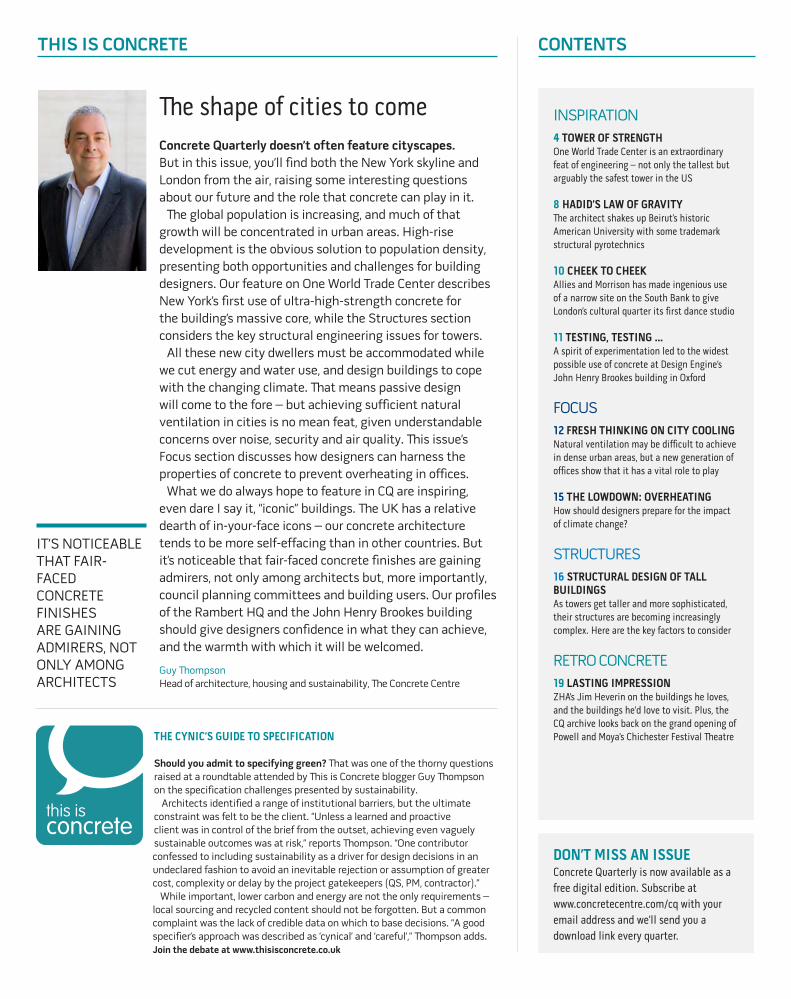
The Issam Fares Institute is approached along a sinuous elevated walkway, threading between 150-year-old cypress trees and passing beneath the gravity-defying cantilevered mass of the upper floors, before reaching the entrance, on the first floor of one of its stark, angled facades. All of this is made from concrete, even the distinctive cantilevered benches cast into the shaded courtyard created by the 21m overhang.
This five-storey political research building was created by Zaha Hadid Architects at the American University of Beirut, and its unusual cantilevered
form is a radical and spectacular response to its location. Situated on the university’s historic central square, the elevated site offers views across the campus and down to the Mediterranean Sea beyond. ZHA’s design sets out to preserve the sea view and pedestrian routes across the campus by lifting the bulk of the 3,000m2 building 11m above the square. According to project architect Saleem A Jalil, it was this inspired approach to opening up the campus that won ZHA the design competition back in 2006.
In-situ concrete was fundamental to realising this dramatic concept. “The building is very massive, dominant on the outside. We didn’t want it to fit in, we wanted it to change the status quo but to give spatial continuity,” Jalil says. “We decided to do it in fair-faced concrete as opposed to cladding it because it was one of those projects
INSPIRATION | ISSAM FARES INSTITUTE
that gave itself to the use of concrete. If you’d built it in steel you would not have achieved any of this.” Fortunately, the local contractors were very familiar with the use of fair-faced concrete and skilled in its application.
For contractor Kettaneh Construction, building the cantilevered third and fourth floors was one of the biggest challenges. The cantilever is supported on giant Y-shaped horizontal beams that spring from a series of inclined vertical columns hidden within the building’s core. The beams taper from a depth of 1.8m to 0.3m at the farthest point, and were cast in situ, supported on a forest of props.
The structure’s efficiency is enhanced by post-tensioning the concrete slabs on the two overhanging floors. To do this, high-strength steel strands were embedded in the floor plates. Once the concrete had cured, these strands were tensioned to keep the slab in compression. This technique helped counteract structural deflections and ensured a very efficient structure, minimising material use and weight. The fact that the depth of the slabs was halved from 600mm to 300mm, the same as the conventionally constructed floor plates, also had the aesthetic benefit of allowing the facade geometry to remain uniform.
The building’s distinctive facade treatment

PROJECT TEAMArchitect Zaha Hadid ArchitectsStructural engineer Rafik El-Khoury & PartnersContractor Kettaneh Construction
sets it apart from its sandstone-clad neighbours. Rows of inclined parallelogram-shaped windows are recessed into the 400mm-thick fair-faced concrete walls. The ghosts of openings fill the spaces between the window perforations. These are formed by recessing the concrete 20mm to give what Jalil describes as “a rhythm” to the facade, enhanced by additional linear recesses to create the illusion of concrete joints: “It’s a play of positive and negative using concrete.”
The walls slant at various angles, adding further drama but also playing a key structural role, as they are designed to resist lateral loads, keeping the interior free and open. “There isn’t a single vertical wall in this building, and apart from two feature columns in the lobbies the interior is completely column free,” says Jalil. The walls are packed with steel reinforcement, which is threaded between the window recesses. Wooden shuttering was used to form the inner and outer surfaces and to shape the window penetrations, and initially the plan was to construct sections of the wall, one floor level at a time, by pouring concrete into the shuttering from above. But the sheer quantity of reinforcement presented a challenge: “The reinforcement was so dense that you could not get the hose between it, which made it difficult to ensure all of the voids were filled with concrete.”
FAR LEFTThe concrete structure does not contain a single vertical wall
LEFTFair-faced concrete is also used on the roof terrace and external furniture
Phot
os: H
ufto
n +
Crow
The problem could have been resolved by pumping super-fluid concrete directly into the base until the shutter was full to the brim. As a more cost-effective alternative, the team developed a solution using what Jalil terms “normal concrete”, with the addition of plasticisers to help it flow. This was then injected through holes cut halfway up the 3.5m shuttering. When the concrete reached the level of the hole, it was blanked off and the pour continued from the top.
Altogether 2,400m3 of concrete was poured to complete the facades. Internally, the finish was not an issue as the walls were topped with a layer of insulation and plasterboard mounted on timber studs, with internal walls of glass patterned to reflect the window perforations on the facade. Externally, however, a high-quality finish was critical. When the shuttering was removed, any minor defects were made good by a fair-faced concrete repair specialist. It is a technique that worked, says Jalil: “Most people find it hard to believe the finish has been achieved in situ using a standard concrete mix.” P19 ZHA partner Jim Heverin’s lasting impressions
CROSS SECTION 1 Reading room 2 Conference room 3 Seminar room 4 Researchers’ lounge 5 Auditorium 6 Researchers’ office 7 Storage room 8 Breakout room 9 Server room 10 Main stairs 11 Ventilation cavity 12 Lobby 13 Toilets 14 Lift 15 Kitchenette 16 External ramp
FRL m +21.90
FRL m +11.85
FRL m +19.65
FRL m +15.75
FRL m+/- 0.00
FRL m +7.90
FRL m +3.95
FRL m -4.40
FRL m -6.40
102
5m
10m0 1meter
1
2
3
4
6
13 9 5 8
14
10
13
13
15
13
13 12
1212
12
11
16
20m
Nicely Hall 1
1
2
3
4
5
11
16
13 8
6
9 710
12
12
13
13
15 14
13
12

10 | CQ | AUTUMN 2014
CHEEK TO CHEEKAllies and Morrison makes clever use of a tight site on the South Bank to give the Rambert plenty of space to strut their stuff, writes Nick Jones
On the South Bank, London’s fortress of concrete and culture, Allies and Morrison has created an ingenious mini stronghold for contemporary dance company Rambert.
One block back from the river, the Rambert HQ is an elegant response to the illustrious complex across the road. The facade is of precast concrete in a familiar South Bank grey, with two projecting dance studios expressed in bronze anodised aluminium. “The use of concrete allowed us to make a connection with the National Theatre,” says Nick Peri, project director for Allies and Morrison. “We chose a finish that looked as much like in-situ concrete as possible.”
Peri says the facade design was actually still being fleshed out when Allies and Morrison won the competition back in 2004. Instead, what impressed Rambert was the way that a huge number of functions – including three double-height rehearsal studios, offices, an archive and a vast loading bay for a 16-tonne truck – were packed into such a small building. “It’s a bit of a Tardis,” says Peri. “You can’t quite believe all this is in there.”
The building is a Tetris-like arrangement of single and double-height spaces. The ground floor is extra high to accommodate the loading bay, where the company assembles its costumes and other equipment before going out on tour. Above this, at the back of the building, the staggered spatial arrangement begins with the impressive two-storey main dance studio.
This studio uses the full width of the building to replicate the 18m stage at Sadlers Wells (the largest performance space that Rambert uses). In order to create this column-free area, the back of the building is spanned by a series of prestressed concrete double T-beams. All of the T-beams were fabricated from a single bespoke steel mould, as no standard models had a profile deep enough to carry the span.
The rest of the structure, including the two staircases, is in-situ concrete, used both for its thermal mass and for aesthetic reasons: “It has a bit of an edge,” says Peri, “which reflects Rambert as a creative company.” The tightly organised
CLOCKWISE FROM ABOVEThe 18m-wide main studio is spanned by prestressed concrete double T-beams; an internal courtyard draws light into the heart of the building; the facade combines precast concrete and aluminium bays
Phot
os: N
ick
Gut
trid
gePROJECT TEAMArchitect Allies and MorrisonStructural engineer Buro Happold Contractor VinciConcrete contractor Mitchellson
programme of staggered spaces rises up for five storeys, including the other double-height studios on the second and fourth floors, and a peaceful courtyard that plunges into the heart of the structure at level three. This plays a key role in the natural ventilation and daylighting strategy of the deep-plan building, which has no windows on the side elevations due to
INSPIRATION | RAMBERT
developments planned on either side.The Rambert’s new HQ is a far cry from its
previous home – a rundown collection of buildings in Chiswick where one rickety studio had a sign that said (helpfully), “Please don’t jump on the floors”. One suspects that this clever and robust addition to the South Bank will withstand even the most dynamic routines for many years to come.

ABOVEThe lecture theatre is suspended in the heart of the forum
RIGHTThe facade combines precast concrete panels and large expanses of glazing
BELOW RIGHTExposed in-situ concrete in the lecture theatre helps the passive cooling strategy
Phot
os: N
ick
Kan
e
PROJECT TEAMArchitect Design EngineStructural engineer Ramboll Environmental engineer Grontmij Contractor Laing O’Rourke Cost consultant Turner & Townsend
TESTING, TESTING…Extensive on-site experimentation was the key to the high-quality concrete finishes at Oxford Brookes’ new flagship building, finds Nick Jones
There’s nothing unusual about a research lab on an Oxford campus, but you wouldn’t usually expect to find it set up in the middle of a building site. At Oxford Brookes’ £83m John Henry Brookes building, however, that is exactly what happened.
“We had a site architect there from day one, working with [contractor] Laing O’Rourke on full-size mock-ups of columns, column junctions, beams and coffers,” explains John Ridgett of architect Design Engine. “One end of the site became a kind of concrete laboratory.” The result is not only a robust, flexible university building, but one that uses concrete in pretty much every way possible.
The John Henry Brookes building brings together a new library, lecture theatre, teaching and dining areas, based around an airy central forum and linked to the refurbished 1950s Abercrombie building next door. One of the new building’s most immediately obvious features on entering is its in-situ concrete frame. This has been left exposed, partly to exploit thermal mass and partly because it allows the construction and architecture students who will use the building to see exactly how it was put together. Different finishes have also been used to subtly express the hierarchy of the building’s various functions. The quality of the concrete casting was therefore critical – which is where the laboratory came in.
“In pretty much all of the areas you see, we have obsessed about the concrete,” says Ridgett. For the board-marked walls in the forum, tests were carried out using planed and rough-sawn timber, different waxes, and even different nail fixings. Trials on the coffered library ceiling, meanwhile, focused on getting the same finish from the soffit’s plywood shuttering and the fibreglass moulds used for the coffers. “Eventually we used a primer to etch the moulds, so the texture is as monolithic as possible.The (30%) GGBS gives the concrete a lighter tone and almost the quality of stone.”
There are a number of precast elements, which helped to save time on site. These included the soffits and most of the columns in the Abercrombie extension, and all 12 staircases. Here too testing was paramount, with great care taken over the stairs’ junctions and stainless-steel nosings.
For Ridgett, the level of experimentation has been key to the project’s success – which includes a RIBA national award. “Our approach was to spend a huge amount of effort and care before casting, but when that concrete was struck, that was it. If there are natural variations, that’s what concrete is.”
INSPIRATION | JOHN HENRY BROOKES BUILDING

12 | CQ | AUTUMN 2014
FOCUS | NATURAL VENTILATION
FRESH THINKING ON CITY COOLINGNoise and pollution make natural ventilation a challenge in cities, but recent high-profile London projects are showing the benefit of passive approaches, writes Tom De Saulles
London is set for a renewed wave of office building after a sharp rise in demolitions and preparation of sites for new construction. But in contrast to previous booms, developments are increasingly likely to incorporate passive design measures, such as provision for natural ventilation.
Providing ventilation to office buildings in urban environments has always presented a particular set of design challenges. Traditionally, a mechanical approach has been favoured to address issues of noise, security and air quality, and to minimise heat loss during the winter months. This continues to be the case, although today’s more environmentally conscious design briefs can lead to more holistic ventilation strategies that involve the use of a mixed-mode system – that is, one that combines mechanical and natural ventilation.
Drivers include a greater emphasis on running costs and a preference for openable windows, as well as the desire to provide some adaptability to our warming climate – something that investors are becoming keenly aware of as a means of future-proofing their property assets. Similarly, the provision of natural ventilation can provide greater resilience in the event of a summer power outage, which is a particular concern in London where the collective air-conditioning load can strain the National Grid.
The urban ventilation challengeIn London, recent examples of the mixed-mode approach can be found at Romero House in Southwark, the headquarters of charity CAFOD, and in two of the new offices at the ongoing King’s Cross development, One and Five Pancras Square (see boxes 1 and 3). While the specific ventilation strategy varies between projects, the execution is
n Combined wind and stack ventilators, providing a roof-mounted solution where openable windows and/or atriums are not an option n Openable ventilation doors/panels within the facade, protected by external security louvres and a wire mesh to keep out insects and verminn Night-time ventilation of exposed concrete soffits to make good use of the diurnal change in air temperaturen Sympathetic siting of mechanical ventilation
ALL OF THESE PROJECTS FEATURE EXPOSED CONCRETE SOFFITS, WHICH PLAY A KEY ROLE IN THE SUMMERTIME VENTILATION STRATEGY
part of a bigger picture in which the architecture is thoughtfully integrated with the heating and cooling approach. In particular, all of these projects feature exposed concrete soffits, which play a key role in the summertime ventilation strategy, as the soffit absorbs excess heat during the day and is purged by night-time ventilation.
This is more than just a passive means of removing excess heat, however – it can also be thought of as a way of maximising and extending the cooling potential of ventilation. In other words, it enables the benefit of comparatively cool night air to be transferred to the following day, when the external temperature is warmer. It can also lessen the impact of noise and pollution by reducing the need for natural ventilation during the daytime.
The potential for night cooling is reduced by the urban heat island effect, but it can still be an effective technique, albeit less so in the centre of London under heatwave conditions. In practice, most urban office buildings with a mixed-mode system will also have some form of air conditioning, with natural ventilation used during favourable weather to avoid or minimise the energy used by fans, pumps and chillers. This is underpinned by the principal design objective of mixed-mode systems, which is to sustain natural ventilation as long as possible while maintaining comfortable conditions.
Recent projects have made considerable progress towards overcoming the urban ventilation challenge, due to some original thinking on the part of design teams. A good example can be found at 55 Gee Street in Clerkenwell by Munkenbeck + Partners (see box 2, overleaf).
In more general terms, techniques that can be suited to urban environments include:n Double-skin facades in high-rise buildings, to act as an acoustic buffer against external noise and lessen the effect of high wind speedsn Ventilation towers and atriums to promote stack ventilation, a useful means of inducing air flow, particularly in built-up locations where wind speeds may be reduced

1 One Pancras SquareDavid Chipperfield Architects, completed 2014
Built over eight floors, this office building has a prime spot at the gateway to London’s King’s Cross development, and is notable for the use of textured iron columns around its perimeter in a
nod to the site’s Victorian heritage. It has just become the first speculative office development to secure a BREEAM outstanding rating. The narrow, column-free floor plan allows the building to be naturally ventilated via openable panels on either side of the windows. Mechanical ventilation is also provided, as is cooling from chilled beams located on an exposed concrete soffit, enhancing the building’s passive cooling capability.
intake grills to minimise entry of street-level pollution and hot air emanating from facades and road or paving that is directly exposed to the sunn The use of high-thermal-mass air shafts to bring fresh air into the building from roof level, helping to tackle noise, security and pollution issues, while also providing additional coolingn Relatively narrow, unobstructed floorplates to help maximise cross-ventilation from perimeter windows.
Phot
o: J
ohn
Stur
rock

14 | CQ | AUTUMN 2014
FOCUS | NATURAL VENTILATION
2 45-55 Gee StreetMunkenbeck + Partners, completed 2010
45-55 Gee Street in Clerkenwell, London combines a long, thin office building with six apartments alongside, in order to meet a planning requirement for a mixed-use development. The office building has an innovative rooftop air-mixing ventilation
system with an exposed concrete soffit for thermal mass. The distinctive perforated-brick facade, pictured below, allows additional natural cross-ventilation.
The development should not require heating or cooling when the outside temperature is between 0-28°C, which is expected to be the case for about 11 months of the year.
3 Five Pancras SquareBennetts Associates, completed 2014
Five Pancras Square is the administrative headquarters for the London Borough of Camden, as well as providing a new community facility. The building has a central atrium and open balcony arrangement to facilitate passive stack ventilation and optimise daylighting. Windows will
The human factorProviding occupants with some control of the ventilation is part of the passive design approach, although the extent to which this works is as much about buy-in and company culture as it is about the design itself. However, much can be done during the handover period to set occupants on the right path by properly conveying the design intent and the extent to which they are able to regulate their environment. Another important success factor is the way in which automatic ventilation control is integrated with occupant control – the less intrusive the better.
One option is a semi-automatic approach to window control, a system used at the National Trust headquarters in Swindon. This allows windows to be opened manually, but will automatically close them after an hour or so if the building management system determines it
is too hot or cold outside for natural ventilation. This helps to minimise the risk associated with occupant control while still providing the psychological benefit that comes from being able to open a window.
A slightly different approach is used at both the RSPCA headquarters in West Sussex and at Plantation Place, London, where staff receive an email alerting them that “today is a natural ventilation day, feel free to open your window”. A novel alternative to email is the BMS-controlled traffic-light system used at the BT offices in Brentwood. Here, coloured lights located around the top of internal concrete columns provide a visual guide as to whether windows can be opened or should be kept shut.
More recently, at its White Collar Factory on City Road, developer Derwent London is planning to introduce a dedicated building app to alert
occupants on “green days” when they can open the windows.
Whatever means is used to control ventilation during the day, the building will usually revert to automatic control in the evening, to optimise night cooling. This typically involves closing low-level windows used by the occupants and opening automated upper fanlight windows to regulate air flow in response to temperature, wind speed and direction. Mechanical ventilation may also be used if necessary to increase the ventilation rate.
Numerous case studies show that the simplest approach is invariably the best, as there is less scope for operational problems. This is supported by the Building Services Research and Information Association (BSRIA), whose research on ventilation and night cooling concluded that a complex control strategy is not necessary to maintain comfortable conditions and achieve energy savings.
Phot
o: D
enni
s G
ilber
t/V
IEW
pict
ures
.co.
uk

However, it did identify that careful selection of the control set point to initiate night cooling was of great importance to avoid over- or under-cooling of the building.
ConclusionProviding effective natural ventilation in London and other urban environments is a challenge, but the drivers for it are growing. The available design techniques are also developing, as can be seen on a number of recent heavyweight buildings. Tackling the urban heat island effect is likely to be a key issue for architects and designers in the future. On the plus side, London’s air quality has improved over recent decades, though there is still considerable scope for improvement, particularly in the City. Tom De Saulles is senior manager, building sustainability at The Concrete Centre
THE LOWDOWN: Overheating
Getting ready for life in a hotter climateAdaption to climate change is becoming a major concern for commercial developers and designers. Elaine Toogood outlines key ways of future-proofing internal environments
The issue of overheating is rising up the agenda. The Zero Carbon Hub is well under way on a detailed analysis of the scale of the problem in housing and potential mitigation strategies. The Committee for Climate Change Adaption 2014 Progress Report identifies the need to “design new buildings to be safe and comfortable in a hotter climate”. And there are also new credits available in BREEAM New Construction 2014 to demonstrate that the design accommodates, or can be adapted to maintain, thermal comfort for a projected climate change scenario.
This raises a number of vital questions for developers and their design teams, particularly on non-residential projects which often rely on mechanical cooling. What is the right balance for a client to strike between capital build costs and the risk of overheating, now and in the future? How far do project teams need to go over and above present requirements to account for the impact of climate change? And how can they be confident that their energy and services strategy will continue to allow occupants of the building to remain comfortable as the temperature rises?
Fabric firstThe fabric first approach, already established as the appropriate means of achieving low-carbon housing, can help to maintain comfortable temperatures in non-residential buildings too. In offices, a passive strategy focuses not just on the building envelope, but also on the internal fabric – usually the underside of a structural floor exposed as the finished ceiling. The high thermal mass of the concrete, together with natural ventilation for night-time cooling of the structure, can effectively reduce the heating and cooling load of the building. (Incidentally, this is also an effective strategy for housing but is particularly appropriate for the deeper floor plates and higher
internal heat gains more often associated with non-residential uses.)
Another simple means of temperature control is to maximise floor-to-ceiling heights, which allows warm air to rise above the occupied space, thereby maintaining a comfortable internal environment for longer. Taller floor-to-ceiling heights also mean that buildings are more adaptable for future uses, as there is more space to install surface-mounted services.
It is important to note, too, the key role played by thermal modelling. Software-compatible weather files are available from CIBSE to evaluate the impact of varying climate change and lifecycle scenarios on the performance of a building design.
Mixing it upOf course, a building services strategy does not need ventilation to be exclusively natural or mechanical. Mixed-mode strategies are common, using natural ventilation for much of the time but with a boost of mechanical warmth or cooling when needed. The balance of passive to active operation is likely to change with the seasons, or simply in extreme weather conditions or at times of intense building use. The idea of building in back-up heating or cooling in this way, to an otherwise passive system, gives assurance and flexibility, as well as a low-energy solution. It also helps to future-proof the building for alternative uses and changes in climatic conditions.
A mixed-mode solution that is gaining popularity in the UK uses plastic pipes embedded into concrete floor slabs. Sometimes called thermally active building systems (TABS) or concrete core cooling, they are effectively a hidden asset that provides additional radiant cooling at a low carbon cost, especially if using naturally cooled water such as ground water.
The Concrete Centre publication, Concrete Floor Solutions for Passive and Active Cooling, contains information and case studies on a range of solutions. Recently published research by Mott McDonald for Uponor also provides useful comparison and whole-life costs between TABS and other heating and cooling systems for a “typical” UK office. Elaine Toogood is an architect at The Concrete Centre
HOW CAN PROJECT TEAMS BE CONFIDENT THAT BUILDING OCCUPANTS WILL REMAIN COMFORTABLE AS THETEMPERATURE RISES?
be openable at night to cool the building, which incorporates an exposed concrete frame and painted concrete soffits. Mechanical cooling and ventilation is provided by a displacement system. The building is expected to achieve carbon emissions 50% lower than required by 2010 Building Regulations, and is one of the first inner-city buildings in the UK to achieve a BREEAM outstanding rating.
Phot
os: H
ufto
n +
Crow

16 | CQ | AUTUMN 2014
STRUCTURES | TALL BUILDINGS
STRUCTURAL DESIGN OF TALL BUILDINGSAs towers continue to get higher, concrete plays an ever more vital role in their complex structural design. Gordon Clark and Andy Truby outline the key factors to consider
The combined effect of rapidly rising populations and lack of space in cities means that many countries are building taller. In London alone, there are more than 200 new towers either under construction or in planning.
A building can be thought of as tall if it is at least 30 storeys high or has a height-to-width ratio of five or greater – although the precise definition is always a matter of debate. One thing that is certain, however, is that building at such heights presents unique challenges both in terms of design and construction.
The height of a building can affect the various professional disciplines in different ways. For the structural engineer the key factor is the relative magnitude of the lateral loadings (wind and seismic) when compared to the vertical loadings. The lateral loadings will almost certainly influence the size and strength of the structural elements.
Most of the tall and super-tall buildings in the world are concrete-framed. In addition to the vertical and lateral loadings, the issues that will influence the design of these structures include the requirements of the core, the distribution of services, the fire strategy, axial shortening and tolerances, and the dynamic behaviour of the building. There are also buildability factors to consider, such as floor construction time and hoisting of materials.
Planning the coreThe core of a tall building forms the spine for vertical transportation and services, but it is also probably the most fundamental structural
element. There can be a wide choice of size and shape, which is dictated in part by the geometry of the building and the site. However the overriding factor is the lifts. It is essential that the lift strategy for the building is well understood even at the early concept design stage. The number of lifts is primarily dictated by the occupancy of the building, which is in turn dictated by its use. Only once the number and size of the lifts has been established can the planning of the core begin.
The two key aspects of the core’s structural design are the strength of the concrete and the thickness of the walls. As buildings rise to extreme heights, the strength of concrete required at the base can be as high as C90/105, although for modest tall buildings a lower strength of around C50/60 is usually adequate.
Core walls will be sized to resist the applied loadings, and thicknesses can vary from 350mm to 600mm or more for buildings up to 200m tall. Such wall thicknesses can be unfamiliar to design teams not used to working on tall buildings. It is therefore important for the structural engineer to make an early estimate of the wall thickness to allow the architectural planning to progress based on appropriate structural zones.
The core generally acts as a vertical cantilever taking both vertical and lateral loadings with the outer columns supporting principally vertical loadings. When planning the core, the layout of columns should be configured so that the core supports a larger share of the vertical loading as this assists with resisting overturning from lateral loads. Spacing of columns away from the core should, therefore, ideally be maximised. The core may typically support about 60% of the vertical loading, with the columns supporting the remaining 40%. Figures 1 and 2 show a conventional core and one that uses mega columns.
Fire considerationsFire escape requirements must also be considered early in the process. The escape strategy is key to many aspects of the design, including:n Location, size and number of escape stairs
n Width and details for escape stairsn Requirements for wet/dry risersn Provision for firefighting lifts/shafts.
All of these factors can have an impact on the space provision within the core and therefore must be given due consideration while planning the core layout.
Wind and seismic effectsWhere possible, the core should be placed close to the geometric wind centre or the seismic mass centre of the building, in both directions. Where this is not possible, the torsional or twisting loads on the core should be accurately determined and designed for. This can be particularly important for non-vertical or geometrically complex buildings.
For buildings over 250m, it is common to provide alternative structural stability systems such as bundled tubes, mega frames and outriggers. Such systems look to mobilise the full width of the building and use the perimeter columns to
STANDARDISATION OF ELEMENT DIMENSIONS AND EARLY-AGE STRENGTH GAIN OF THE CONCRETE MIX CAN HAVE A BIG INFLUENCE ON THE FLOOR-TO-FLOOR CYCLE TIME

increase the restoring moments.The lateral loads on tall buildings from both wind
and seismic effects can be extreme and, combined with the vertical loads, govern the building’s overturning moments. Factors such as topography and nearby buildings – both existing and those planned for the future – can cause significant localised increases in loads. Wind tunnel testing is often required to examine their effects.
One great advantage of concrete towers is that their inherent weight naturally enhances structural stability. This mass and the contiguous nature of the construction of concrete-framed towers also provide a greater degree of structural damping, dissipating cyclical sway from lateral forces.
Flooring systemsFlooring systems are predominately either post-tensioned or reinforced-concrete flat slabs, or beam and slab. The use of precast or hybrid construction is becoming common because it enables shorter build programmes.
The use of post-tensioned slabs is often an advantage in tall buildings, as the reduction in slab thickness accumulated over many storeys can result in an additional storey within the same overall height, thus providing greater occupancy and return on investment. Alternatively, maintaining the number of storeys but reducing the overall height of the building can lead to significant cost savings in facade systems.
When designing the floors of a tall building, many of the skills from low-rise construction can be used. However, the floors may be required to resist very large lateral forces due to wind and seismic loadings, which can require additional design load cases and the provision of further reinforcement details to ensure the required degree of ductility.
ConstructionIt is important at the planning stage to consider buildability. Speed of construction of high-rise
ABOVEThe Shard at London Bridge, designed by Renzo Piano Workshop with WSP as structural engineer, is 310m tall and has a slip-formed core
FIGURE 1: PLAN OF A BUILDING WITH A CONVENTIONAL CORE, TYPICALLY USED IN BUILDINGS WITH UP TO 40 STOREYS
FIGURE 2: PLAN OF A BUILDING WITH MEGA COLUMNS, SUITABLE FOR BUILDINGS OF AROUND 50-60 STOREYS

18 | CQ | AUTUMN 2014
STRUCTURES | TALL BUILDINGS
buildings is very important as clients want occupation of the building to begin as quickly as possible to maximise the return on investment. Standardisation of element dimensions and early-age strength gain of the concrete mix can have a big influence on the floor-to-floor cycle time.
Cycle times of between five and seven days are typical for most tall buildings. Use of complicated formwork systems such as ribbed and waffle slabs should be avoided as this slows down the cycle time.
NEW TECHNICAL GUIDANCE
The Concrete Centre and fib International are publishing technical guidance on the design of concrete tall buildings, covering structural systems, design process and loading. The new guide will be launched at the Structural Design of Tall Buildings conference at the Hilton London Tower Bridge on Thursday 23 October. For more details on the conference, and to book tickets, go to www.concretecentre.com/events.
Designing for movementWhen building tall it becomes very important to consider tolerances and drift. A small deviation on each column can add up cumulatively to a major deviation over several storeys. Lateral drift limitation would typically be about H/400, so for a 200m tower this equates to 500mm. Differential shortening between columns and core walls should be considered as the permanent stresses in the core concrete are often less than those in the columns and this causes lateral movement.
It is usual for the cladding to follow the floor-
ABOVE At 180m, the Torre Cajasol in Seville will be the tallest building in Andalucia when it is completed next year. Its structure consists of a reinforced-concrete central core, 14 RC pillars around the perimeter and RC slabs
Phot
o: ju
jo87
/Flic
kr
by-floor construction upwards and the influence of shortening and changes in loading in the lower floors needs to be accommodated in the design of the cladding/facade systems. It is normal practice to install the facade from the inside of the building to avoid the need for external access systems but this requires careful specification and manufacture of the cladding materials.
The way that the building responds to wind also has to be considered as human perception of acceleration can cause discomfort, and damping should be examined. Obtaining agreement on acceptable acceleration levels can be difficult but current guidance recommends the following limits:n Residential: 10-15 milli-gn Office: 20-30 milli-g
Eccentric loading can be an added complexity in the design of tall buildings. Some tall buildings are constructed out of plumb so that they straighten up when completed. However, predicting the effects of creep and shrinkage is difficult. The effect of time has been introduced as an important design criterion in the Model Code for Structural Concrete 2010 published by the international structural concrete federation, fib International.
Holistic approachWhen setting out to design a tall building it is clear that the structural engineer must work closely with the architect, the building services engineer and the lift, fire and facade specialists to address the various factors that influence the layout of the building, and in particular the core. Each party has a vital role to play, but only by working together to understand the issues involved can the optimum solution be established. Tall buildings are monumental, and in many cases iconic, and their design needs the closest possible attention to ensure that they will serve our society in a sustainable way long into the future.Gordon Clark is president of fib and Andy Truby is chairman of fib Task Group 1.6 – Tall Buildings
Key references
J Walraven, fib Model Code for Concrete Structures 2010: Mastering Challenges and Encountering New Ones, Structural Concrete, Vol 14, Nr 1, pp3-9
GM Clark, Challenges for Concrete in Tall Buildings: fib Structural Concrete, DOI: 10.1002/suco.201400011

RETRO CONCRETE
LASTING IMPRESSIONJIM HEVERIN
REVIVAL OF A THEATRICAL CLASSICThe Chichester Festival Theatre, which has just reopened after a £22m refurbishment by Haworth Tompkins, was “a pioneer in English theatrical design”, according to CQ when the curtain went up on Powell and Moya’s bold modernist auditorium 52 years ago. Not that there was a curtain: Chichester was the UK’s first modern thrust stage, with no proscenium arch, little scenery and the actors “thrust” out into the audience.
This dramatic functionalism was reflected in the building design, with Powell and Moya’s novel hexagonal form determined by the shape of the stage and auditorium – an “adventurous step”, according to CQ. As with the productions inside, the mechanics of the construction were given a starring role: “The supporting skeleton is exposed on the outside, and both columns and beams are of structural concrete, cast in situ and bush-hammered to expose the grey aggregate,” noted CQ. Inside, “the soffits are left as they came from the formwork and simply painted white”.
Over the years, the building has suffered from that old theatrical problem of over-direction, with a number of extensions compromising the clarity of the original design. Enter Haworth Tompkins, stage left …Access the full CQ archive at www.concretecentre.com/cq
INSPIRED BY ITO’S TOKYO AND THE BUILDING ACROSS THE ROAD …While thinking about this, I realised that I haven’t visited enough of the buildings that inspire me – it’s one thing to admire them from a distance, but to actually see and touch and use a building connects you to it. A lot of the post-war projects by Nervi, Candela, Le Corbusier and many other architects feed into our work, but we also admire contemporary work such as the Angel building by AHMM (2010).
The Angel 1 , just up the road from our office, is a great project, particularly the central atrium. AHMM took a building that wasn’t very interesting and created a lot of quality. It’s good to see concrete coming back into commercial projects, and it’s also pertinent that it’s a refurb – the concrete projects of the post-war generation aren’t appreciated enough.
I’m looking forward to Herzog & de Meuron’s Tate Modern extension. The in-situ staircase will be spectacular, the precast frame looks stunning, and there’s a precast ceiling that I first saw in the Schaulager building 2 in Basel (2003) – we couldn’t figure out whether it was in situ or precast. Water runs through it for heating and chilling, and lighting is placed very precisely in the gaps.
At the moment we are travelling quite a bit to Japan, the kingdom of in-situ concrete. I like the universal application, the fact that it’s used in very ordinary buildings but delivered with amazing skill and care. The facade of Toyo Ito’s Tod’s building 3 in Tokyo (2004) is phenomenal. None of the corners are blunted, the panels are extremely smooth and the finish is so consistent – it’s like polished stone. When that’s applied to a really great building, like his Tama Art university library (which I haven’t seen), it’s an amazing combination of the materiality of concrete, which can be structure and cladding all at once, and this ability to be very permanent and to allow architects to carve out spaces.Jim Heverin is a director at Zaha Hadid Architects
FROM THE ARCHIVE: AUTUMN 1962
1 3
2
Phot
os: 1
.Pet
er C
ook/
VIE
Wpi
ctur
es.c
o.uk
; 2. T
om B
isig
; 3. E
dmun
d Su
mne
r/V
IEW
pict
ures
.co.
uk

FINAL FRAME: CIDADE DAS ARTES, RIO DE JANEIROFrench architect Christian de Portzamparc describes Rio’s new cultural venue as a “little city contained in one big structure”. The scale is astonishing: an 1,800-seat philharmonic hall, a 1,300-seat opera hall, three cinemas, a music school and many other facilities are housed in a series of vast, elevated boxes of exposed concrete. This whole “city” is contained beneath a mighty 46,000m2 slab roof and bounded by an iconic facade of curving concrete fins. Ph
oto:
Huf
ton
+ Cr
ow