Embed Size (px)
Citation preview
Expansion Project of Jag Pravesh Chandra Hospital
at Shastri Nagar, Delhi CONCEPTUAL PLAN
93
Jag Pravesh Chandra Hospital
CONCEPTUAL PLAN
INTRODUCTION
Jag Pravesh Chandra Hospital is a 210 bedded multi-speciality secondary
level Hospital situated in North East District GNCT of Delhi. A total number
of 523 beds are being proposed for the expansion of the project. The main
objective of hospital is to provide free basic health care to the people living in
North East District. Hospital is providing OPD, Round the clock Indoor and
Casualty services including routine diagnostic services in general specialties.
It is intended that all service seekers receive courteous & prompt attention.
The hospital OPD services were started in October 2003 Indoor and casualty
services were commenced later on in 2007 and 2009 respectively.
SITE DESCRIPTION
Expansion Project of Jag Pravesh Chandra Hospital Delhi -110053
The Geographical Co-ordinates of the project site are
Latitude - 28°40'34.32"N
Longitude - 77°15'46.44" E
Google earth image showing project site & surroundings within 500m &
Toposheet showing project site & surrounding within 10 + 15 km are
attached.
CONNECTIVITY
The nearest highway NH-9 is only 3.01 km to the NNE of the project. The
nearest railway station is Hazrat Nizzamuddin Railway Station, approx. 9.27
km away towards East-South-East direction. Anand Vihar metro station is
at app. 6 km in South East direction.
Expansion Project of Jag Pravesh Chandra Hospital
at Shastri Nagar, Delhi CONCEPTUAL PLAN
94
Jag Pravesh Chandra Hospital
The nearest airport is Indira Gandhi International Airport (IGI), which is
approx. 20.76 Km away from the project site in South West direction.
AREA STATEMENT
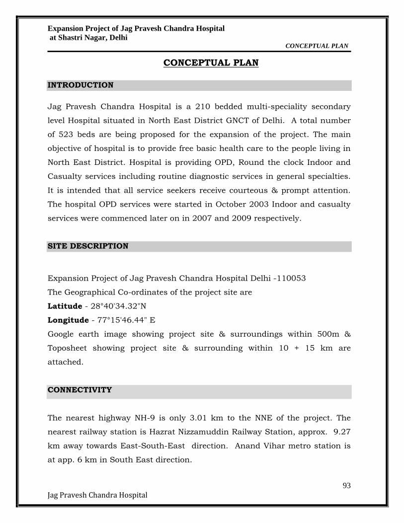
The total area of the project site is 19694 m2. The detailed Area Statement of
the project is provided below in Table-1.
POPULATION DENSITY
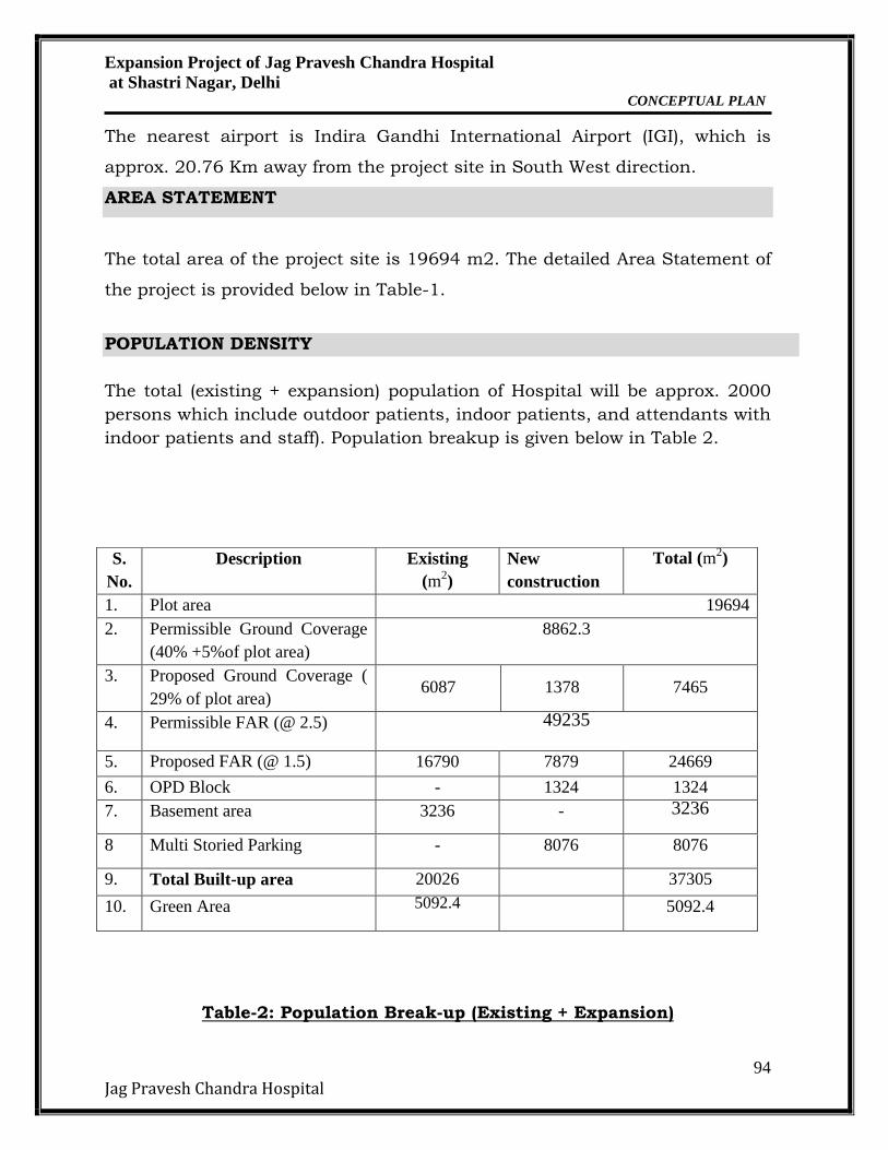
The total (existing + expansion) population of Hospital will be approx. 2000
persons which include outdoor patients, indoor patients, and attendants with
indoor patients and staff). Population breakup is given below in Table 2.
Table-2: Population Break-up (Existing + Expansion)
S.
No.
Description Existing
(m2)
New
construction
Total (m2)
1. Plot area 19694
2. Permissible Ground Coverage
(40% +5%of plot area)
8862.3
3. Proposed Ground Coverage (
29% of plot area) 6087 1378 7465
4. Permissible FAR (@ 2.5) 49235
5. Proposed FAR (@ 1.5) 16790 7879 24669
6. OPD Block - 1324 1324
7. Basement area
3236 - 3236 8 Multi Storied Parking - 8076 8076
9. Total Built-up area 20026 37305
10. Green Area 5092.4 5092.4
Expansion Project of Jag Pravesh Chandra Hospital
at Shastri Nagar, Delhi CONCEPTUAL PLAN
95
Jag Pravesh Chandra Hospital
S.
No Type of population
Existing Expansion Total
A. Outdoor patients 375 500 875
B. Indoor patients 210 523 733
C. Staff (doctors, nurses,
etc.) + Attendants with
IPD patients
180 212 392
TOTAL (A + B + C) 765 1235 2000
WATER REQUIREMENT
The total (existing + expansion) water requirement for the project will be
approx. 360KLD. The water supply will be provided by Delhi Jal Board (DJB).
The fresh water requirement will be approx. 172 KLD. Daily water
requirement calculation is given below in Table 3:
Table 3: Calculations for Daily Water Demand (Existing+Expansion)
S.
No.
Description Occupanc
y
Rate of water
demand (lpcd)
Total Water
Requiremen
t (KLD)
A. Domestic water
Inpatients/Be
ds
733 450 329.9
OPD patients 875 15 13.12
Staff (Doctors
+ Nurses) and
Inpatient
attendants
392 45 17.64
Sub-Total (A) 360.66 KLD
Say 360
B. Horticulture 5092.4 m2 6 l/sqm 30.5
C. DG Sets Cooling*
4200 kVA 0.9 lit/KVA/hr 22.6
Grand total (A+B+C) 413 KLD
*Considering 6 hrs working of DG sets per day
Expansion Project of Jag Pravesh Chandra Hospital
at Shastri Nagar, Delhi CONCEPTUAL PLAN
96
Jag Pravesh Chandra Hospital
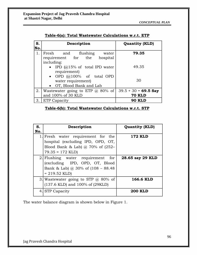
Table-6(a): Total Wastewater Calculations w.r.t. ETP
Table-6(b): Total Wastewater Calculations w.r.t. STP
The water balance diagram is shown below in Figure 1.
S.
No.
Description Quantity (KLD)
1. Fresh and flushing water requirement for the hospital
including:
IPD (@15% of total IPD water
requirement)
OPD (@100% of total OPD
water requirement)
OT, Blood Bank and Lab
79.35
49.35
30
2. Wastewater going to ETP @ 80% of
and 100% of 30 KLD
39.5 + 30 = 69.5 Say
70 KLD
3. ETP Capacity 90 KLD
S.
No.
Description Quantity (KLD)
1. Fresh water requirement for the
hospital (excluding IPD, OPD, OT,
Blood Bank & Lab) @ 70% of (252–
79.35 = 172 KLD)
172 KLD
2. Flushing water requirement for
(excluding IPD, OPD, OT, Blood
Bank & Lab) @ 30% of (108 – 88.48
= 219.52 KLD)
28.65 say 29 KLD
3. Wastewater going to STP @ 80% of
(137.6 KLD) and 100% of (29KLD)
166.6 KLD
4. STP Capacity 200 KLD
Expansion Project of Jag Pravesh Chandra Hospital
at Shastri Nagar, Delhi CONCEPTUAL PLAN
97
Jag Pravesh Chandra Hospital
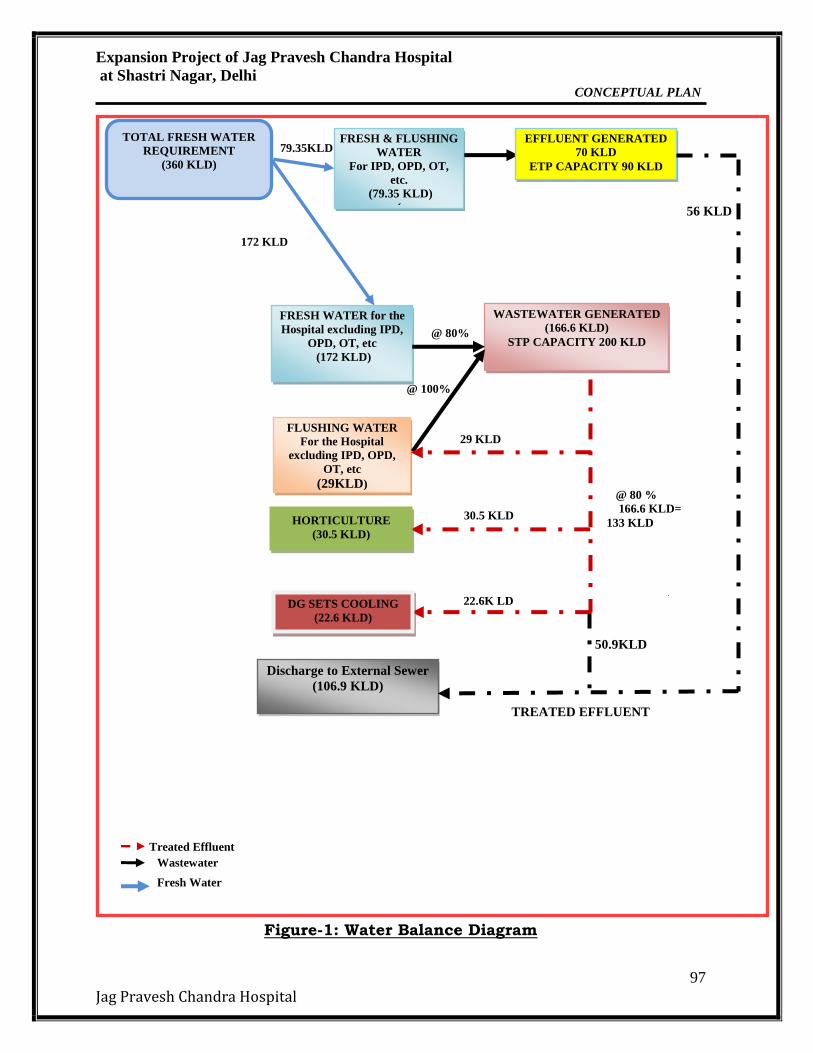
Figure-1: Water Balance Diagram
FRESH WATER for the
Hospital excluding IPD,
OPD, OT, etc
(172 KLD)
WASTEWATER GENERATED
(166.6 KLD)
STP CAPACITY 200 KLD
FLUSHING WATER
For the Hospital
excluding IPD, OPD,
OT, etc
(29KLD)
@ 100%
29 KLD
Wastewater
Fresh Water
TOTAL FRESH WATER
REQUIREMENT
(360 KLD)
FRESH & FLUSHING
WATER
For IPD, OPD, OT,
etc.
(79.35 KLD)
(
EFFLUENT GENERATED
70 KLD
ETP CAPACITY 90 KLD
30.5 KLD
79.35KLD
HORTICULTURE
(30.5 KLD)
@ 80 %
166.6 KLD=
133 KLD
@ 80%
172 KLD
Treated Effluent
Discharge to External Sewer
(106.9 KLD)
TREATED EFFLUENT
50.9KLD
22.6K LD DG SETS COOLING
(22.6 KLD)
56 KLD
Expansion Project of Jag Pravesh Chandra Hospital
at Shastri Nagar, Delhi CONCEPTUAL PLAN
98
Jag Pravesh Chandra Hospital
Waste Water/ Effluent Generation & Treatment
It is expected that waste water (domestic sewage) generated from the project
will be approx. 166.6 KLD(@ 80% of fresh water, 100 % flushing water). The
domestic sewage will be treated in onsite STP capacity of 200 KLD generating
133 KLD of recoverable water from STP which will be reused for Flushing,
Horticulture, DG sets cooling and surplus treated water will be discharged to
sewer.
The wastewater (trade effluent) generated from OPD, IPD, OT, Blood bank and
Labs will be approx. 70 KLD, which will be treated in onsite ETP of 90 KLD
capacity.
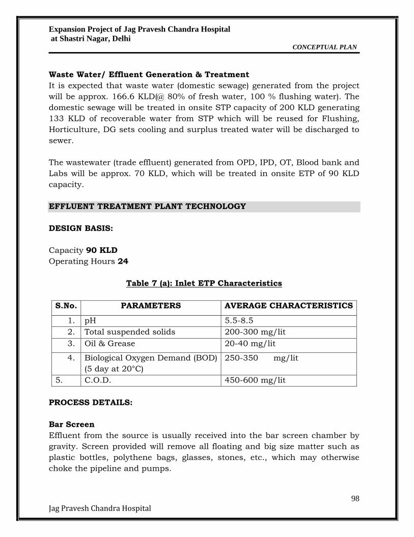
EFFLUENT TREATMENT PLANT TECHNOLOGY
DESIGN BASIS:
Capacity 90 KLD
Operating Hours 24
Table 7 (a): Inlet ETP Characteristics
S.No. PARAMETERS AVERAGE CHARACTERISTICS
1. pH 5.5-8.5
2. Total suspended solids 200-300 mg/lit
3. Oil & Grease 20-40 mg/lit
4. Biological Oxygen Demand (BOD)
(5 day at 20°C)
250-350 mg/lit
5. C.O.D. 450-600 mg/lit
PROCESS DETAILS:
Bar Screen
Effluent from the source is usually received into the bar screen chamber by
gravity. Screen provided will remove all floating and big size matter such as
plastic bottles, polythene bags, glasses, stones, etc., which may otherwise
choke the pipeline and pumps.
Expansion Project of Jag Pravesh Chandra Hospital
at Shastri Nagar, Delhi CONCEPTUAL PLAN
99
Jag Pravesh Chandra Hospital
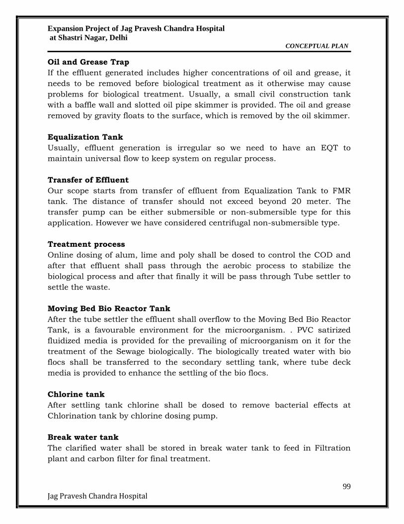
Oil and Grease Trap
If the effluent generated includes higher concentrations of oil and grease, it
needs to be removed before biological treatment as it otherwise may cause
problems for biological treatment. Usually, a small civil construction tank
with a baffle wall and slotted oil pipe skimmer is provided. The oil and grease
removed by gravity floats to the surface, which is removed by the oil skimmer.
Equalization Tank
Usually, effluent generation is irregular so we need to have an EQT to
maintain universal flow to keep system on regular process.
Transfer of Effluent
Our scope starts from transfer of effluent from Equalization Tank to FMR
tank. The distance of transfer should not exceed beyond 20 meter. The
transfer pump can be either submersible or non-submersible type for this
application. However we have considered centrifugal non-submersible type.
Treatment process
Online dosing of alum, lime and poly shall be dosed to control the COD and
after that effluent shall pass through the aerobic process to stabilize the
biological process and after that finally it will be pass through Tube settler to
settle the waste.
Moving Bed Bio Reactor Tank
After the tube settler the effluent shall overflow to the Moving Bed Bio Reactor
Tank, is a favourable environment for the microorganism. . PVC satirized
fluidized media is provided for the prevailing of microorganism on it for the
treatment of the Sewage biologically. The biologically treated water with bio
flocs shall be transferred to the secondary settling tank, where tube deck
media is provided to enhance the settling of the bio flocs.
Chlorine tank
After settling tank chlorine shall be dosed to remove bacterial effects at
Chlorination tank by chlorine dosing pump.
Break water tank
The clarified water shall be stored in break water tank to feed in Filtration
plant and carbon filter for final treatment.
Expansion Project of Jag Pravesh Chandra Hospital
at Shastri Nagar, Delhi CONCEPTUAL PLAN
100
Jag Pravesh Chandra Hospital
Multi Grade Filtration Plant
After Break water tank it will be pumped to filtration plant to treat further
Activated carbon Filter
After Filtration plant filtered water shall be pass through ACF to remove
chlorine and smell and colour.
Final treated water tank
Final treated water shall be stored in final tank for further re- uses and other
low end applications.
Sludge
The sludge from the Clarifier to be removed from the bottom of the Clarifier
once in a week by gravity to sludge holding tank and it will be pumped to
sludge drying beds for final dewatering.
Final solid shall be used as manure and water shall be re-circulated to EQT.
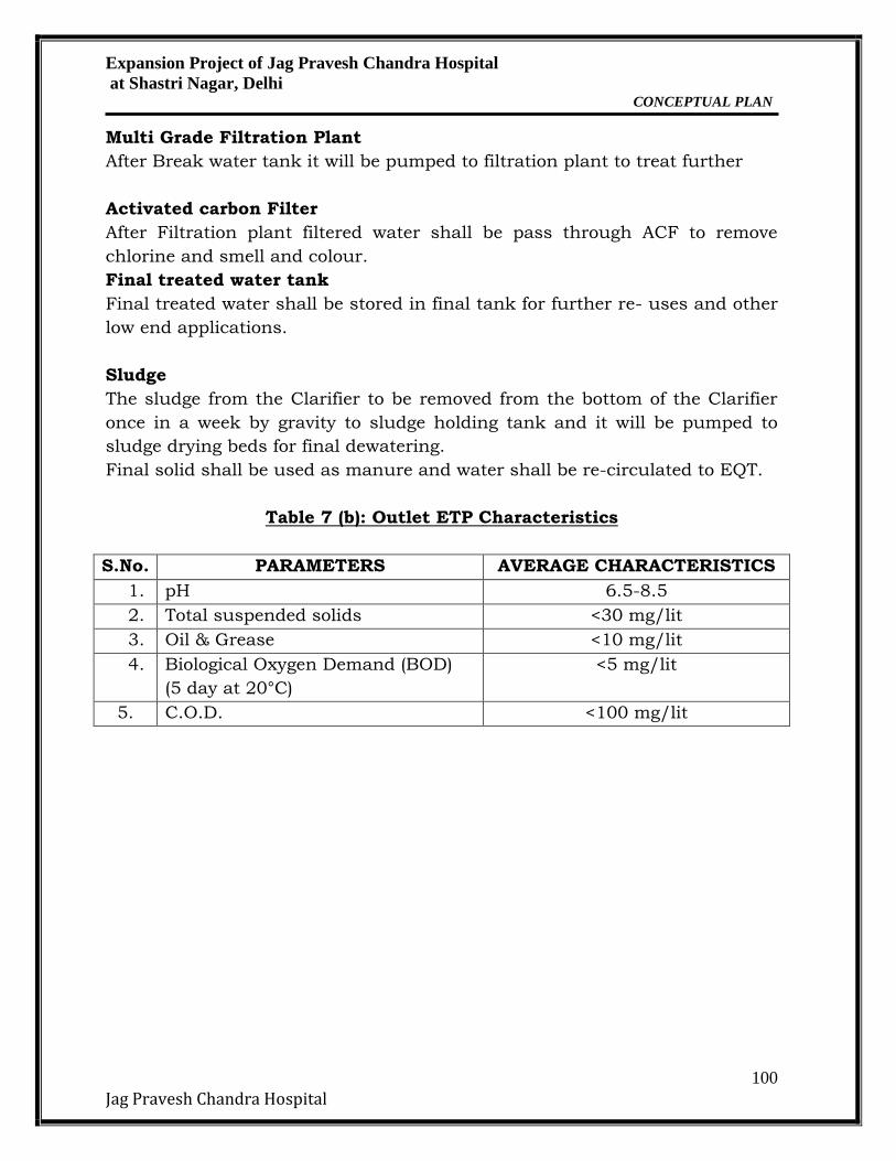
Table 7 (b): Outlet ETP Characteristics
S.No. PARAMETERS AVERAGE CHARACTERISTICS
1. pH 6.5-8.5
2. Total suspended solids <30 mg/lit
3. Oil & Grease <10 mg/lit
4. Biological Oxygen Demand (BOD)
(5 day at 20°C)
<5 mg/lit
5. C.O.D. <100 mg/lit
Expansion Project of Jag Pravesh Chandra Hospital
at Shastri Nagar, Delhi CONCEPTUAL PLAN
101
Jag Pravesh Chandra Hospital
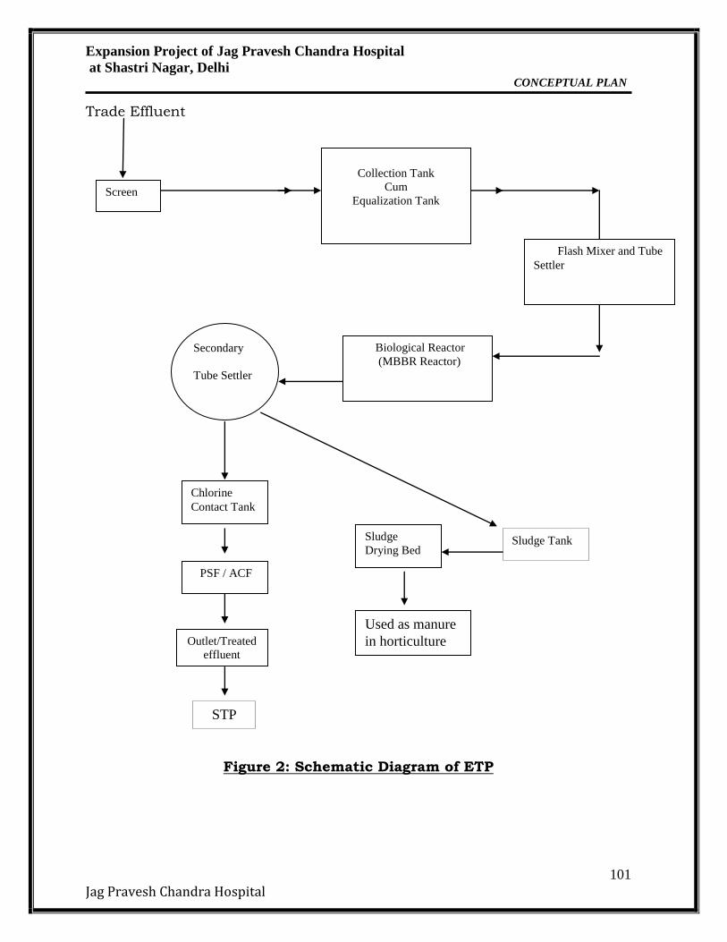
Trade Effluent
Figure 2: Schematic Diagram of ETP
Screen
Collection Tank
Cum
Equalization Tank
Chlorine
Contact Tank
PSF / ACF
Outlet/Treated
effluent
Sludge
Drying Bed
Biological Reactor
(MBBR Reactor) Secondary
Tube Settler
Used as manure
in horticulture
Flash Mixer and Tube
Settler
Sludge Tank
STP
Expansion Project of Jag Pravesh Chandra Hospital
at Shastri Nagar, Delhi CONCEPTUAL PLAN
102
Jag Pravesh Chandra Hospital
SEWAGE TREATMENT TECHNOLOGY
FAB TECHNOLOGY:
Sewerage System
An external sewage network will collect the sewage from all units, and flow by
gravity to the proposed sewage treatment plant.
Following are the benefits of providing the Sewage Treatment Plant in the
present circumstances:
Reduced net daily water requirements, source for Horticultural
purposes by utilization of the treated wastewater.
Reduced dependence on the public utilities for water supply and
sewerage systems.
Sludge generated from the Sewage Treatment Plant will be rich in
organic content and an excellent fertilizer for horticultural purposes.
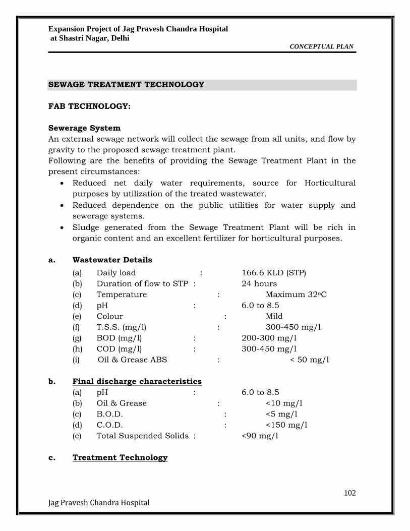
a. Wastewater Details
(a) Daily load : 166.6 KLD (STP)
(b) Duration of flow to STP : 24 hours
(c) Temperature : Maximum 32oC
(d) pH : 6.0 to 8.5
(e) Colour : Mild
(f) T.S.S. (mg/l) : 300-450 mg/l
(g) BOD (mg/l) : 200-300 mg/l
(h) COD (mg/l) : 300-450 mg/l
(i) Oil & Grease ABS : < 50 mg/l
b. Final discharge characteristics
(a) pH : 6.0 to 8.5
(b) Oil & Grease : <10 mg/l
(c) B.O.D. : <5 mg/l
(d) C.O.D. : <150 mg/l
(e) Total Suspended Solids : <90 mg/l
c. Treatment Technology
Expansion Project of Jag Pravesh Chandra Hospital
at Shastri Nagar, Delhi CONCEPTUAL PLAN
103
Jag Pravesh Chandra Hospital
The technology is based on attached growth aerobic treatment followed by
clarification by a tube settler. Lime will be dosed in for suppression of
foaming tendencies. The clarified water will be filtered in a pressure sand
filter after dosing of coagulant (alum) for removal of unsettled suspended
impurities. This water will be passed through an activated carbon filter for
removal of organics. The filtered water from ACF is then chlorinated & stored
in the flushing tank.
The attached growth fluidized aerobic bed reactor (FAB) process combines the
biological processes of attached & suspended growth. It combines submerged
fixed film with extended aeration for treatment of the wastewater.
The wastewater after screening is collected in an equalization tank. The
equalization tank is required for preventing surges in flow & facilitating
equalization of characteristics over the entire quantity of effluent in a given
time. A provision for pre-aeration is made in the equalization tank in order to
ensure mixing & to prevent the sewage from going septic.
The equalized sewage is then pumped into the FAB reactor for biological
processing. The water enters the bottom of the reactor & flows up through the
fixed film media which grossly enhances the hydraulic retention time &
provides a large surface area for growth of biological micro – organisms. The
FAB reactor is aerated by fine pore sub – surface diffusers which provide the
oxygen for organic removal. The synthetic media floats on the water & the air
agitation ensures good water to micro-organism contact.
The FAB treatment is an attached growth type biological treatment process
where in, the majority of biological activity takes place on the surface of the
PVC media. Continuous aeration ensures aerobic activity on the surface of
the media. Micro – organisms attach themselves on the media & grow into
dense films of a viscous jelly like nature. Wastewater passes over this film
with dissolved organics passing into the bio-film due to concentration
gradients within the film. Suspended particles & colloid may get retained on
this sticky surface where they are decomposed into soluble products. Oxygen
from the aeration process in the wastewater provides oxygen for the aerobic
reactions at the bio-film surface. Waste products from the metabolic
processes diffuse outward & get carried away by the wastewater or air
currents through the voids of the media.
The aerated effluent passes into a tube deck settler for clarification. The
theory of gravity tube settler system is that the carrier fluid maintains
laminar flow in the settling media at specified maximum viscosity. These two
Expansion Project of Jag Pravesh Chandra Hospital
at Shastri Nagar, Delhi CONCEPTUAL PLAN
104
Jag Pravesh Chandra Hospital
parameters of a carrier fluid, flowing through a hydraulic configuration, will
determine the velocity gradients of the flow, the height of boundary layer at
the inclined surface and the residence time within the media.
The carrier fluid must be viscous Newtonian, exhibiting a Reynolds number of
less than 1000 and preferably, a number under 400. The laminar flow,
through the inclined tubes, will produce velocity gradients sufficiently large to
form an adequate boundary layer, where the velocity of fluid approaches zero.
Boundary layers are necessary in functioning tube settlers, to allow
suspended solids to separate from the viscous carrier fluid. Under
gravitational forces, they will settle to the hydraulic surface of the tube and
subsequently from the clarifier media.
Since the tubes are inclined at 60 degrees, solids settled on the tubes are
continually discharged down. This downward rolling action increases particle
contact and hence further agglomeration, which increases the sludge settle
ability. Studies show that these agglomerated sludge particles can have a
settling rate in excess of ten times the settling rate of the individual floc
particles in the influent. These heavy agglomerated masses quickly slide
down the 60 degree inclined tube and settle at the bottom of the tank.
At the bottom of the Tube deck, where the sludge leaves the Tube surface, the
larger agglomerated captures smaller particles in the upcoming stream. This
solid contact phenomenon greatly enhances the capture efficiency.
Stages of Treatment: The treatment process consists of the following stages:
Equalization
Bio- Degradation
Clarification & Settling
Filtration
Expansion Project of Jag Pravesh Chandra Hospital
at Shastri Nagar, Delhi CONCEPTUAL PLAN
105
Jag Pravesh Chandra Hospital
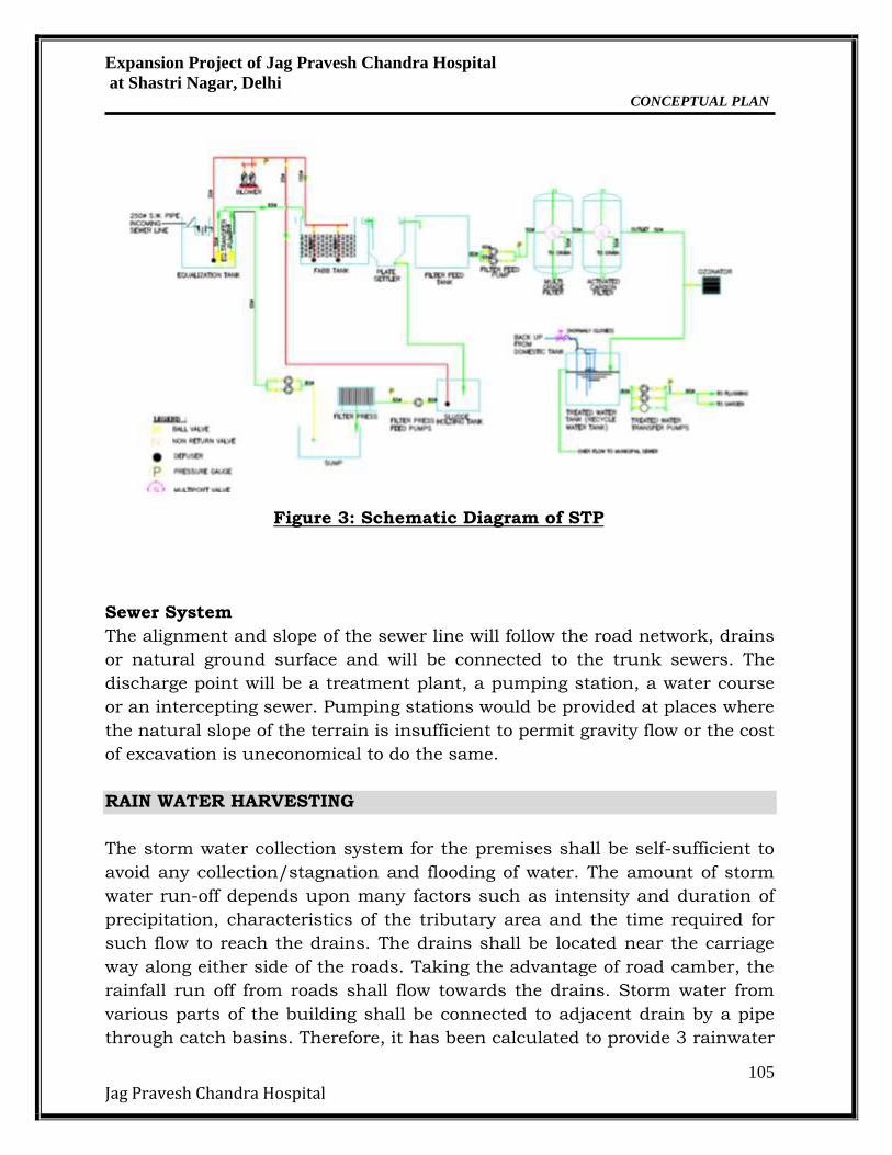
Figure 3: Schematic Diagram of STP
Sewer System
The alignment and slope of the sewer line will follow the road network, drains
or natural ground surface and will be connected to the trunk sewers. The
discharge point will be a treatment plant, a pumping station, a water course
or an intercepting sewer. Pumping stations would be provided at places where
the natural slope of the terrain is insufficient to permit gravity flow or the cost
of excavation is uneconomical to do the same.
RAIN WATER HARVESTING
The storm water collection system for the premises shall be self-sufficient to
avoid any collection/stagnation and flooding of water. The amount of storm
water run-off depends upon many factors such as intensity and duration of
precipitation, characteristics of the tributary area and the time required for
such flow to reach the drains. The drains shall be located near the carriage
way along either side of the roads. Taking the advantage of road camber, the
rainfall run off from roads shall flow towards the drains. Storm water from
various parts of the building shall be connected to adjacent drain by a pipe
through catch basins. Therefore, it has been calculated to provide 3 rainwater
Expansion Project of Jag Pravesh Chandra Hospital
at Shastri Nagar, Delhi CONCEPTUAL PLAN
106
Jag Pravesh Chandra Hospital
harvesting pit at selected locations, which will catch the maximum run-off
from the area.
1) Since the existing topography is congenial to surface disposal, a
network of storm water pipe drains is planned adjacent to roads. All
building roof water will be brought down through rain water pipes.
2) Proposed storm water system consists of pipe drain, catch basins and
seepage pits at regular intervals for rain water harvesting and ground
water recharging.
3)For basement parking, the rainwater from ramps will be collected in the
basement storm water storage tank. This water will be pumped out to
the nearest external storm water drain.
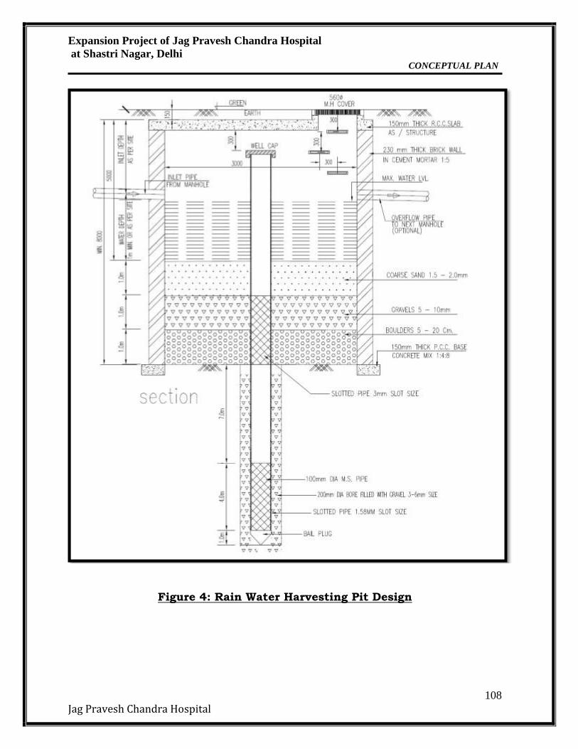
Rain water harvesting has been catered to and designed as per the guideline
of CGWA. Peak hourly rainfall has been considered as 45 mm/hr.
Dimensions of the recharge pits are 6.23m × 2.7 m × 3 m will be constructed
for recharging the water. Inside the recharge pit, a recharge bore will be
constructed having adequate diameter depth. At the bottom of the recharge
well, a filter media is provided to avoid choking of the recharge bore. Design
specifications of the rain water harvesting plan are as follows:
Catchments/roofs would be accessible for regular cleaning.
The roof will have smooth, hard and dense surface which is less likely
to be damaged allowing release of material into the water. Roof painting
has been avoided since most paints contain toxic substances and may
peel off.
All gutter ends will be fitted with a wire mesh screen and a first flush
device would be installed. Most of the debris carried by the water from
the rooftop like leaves, plastic bags and paper pieces will get arrested
by the mesh at the terrace outlet and to prevent contamination by
ensuring that the runoff from the first 10-20 minutes of rainfall is
flushed off.
No sewage or wastewater would be admitted into the system.
No wastewater from areas likely to have oil, grease, or other pollutants
has been connected to the system.
Calculations for storm water load
Roof-top area = Ground Coverage = 7465 m2
Green Area = 5092.4 m2
Paved Area = Total Plot Area – (Roof-top Area + Green Area)
=19694– (5092.4+ 7465)
Expansion Project of Jag Pravesh Chandra Hospital
at Shastri Nagar, Delhi CONCEPTUAL PLAN
107
Jag Pravesh Chandra Hospital
= 7136.6 m2
Runoff Load
Roof-top Area = 7465× 0.045× 0.9
= 302.33 m3/hr
Green Area = 5092.4 × 0.045 × 0.15
= 34.37 m3/hr
Paved Area = 7136.6 ×0.045 ×0.7
= 224.8 m3/hr
Total Runoff Load* = (302.33+34.37+224.8) m3/hr
= 561.5 m3/hr
Taking 15 minutes Retention Time, total volume of storm water = 561.5
/4
=140. 4 m3
The effective length, breadth and depth of a Recharge pit are 6.23 m, 2.7 and
3.0 m respectively. Volume of a single Recharge pit (a) = L X B X H =
6.23m × 2.7 m × 3 m
= 50.463 m3
Hence No. of Rain Water Harvesting pit required = 140.4/50.463
= 2.7 say 3
3Rain Water Harvesting pit has been proposed for artificial rain water
recharge within the project premises.
Expansion Project of Jag Pravesh Chandra Hospital
at Shastri Nagar, Delhi CONCEPTUAL PLAN
108
Jag Pravesh Chandra Hospital
Figure 4: Rain Water Harvesting Pit Design
Expansion Project of Jag Pravesh Chandra Hospital
at Shastri Nagar, Delhi CONCEPTUAL PLAN
109
Jag Pravesh Chandra Hospital
VEHICLE PARKING FACILITIES
Adequate provision will be made for car/vehicle parking at the project site.
There shall also be adequate parking provisions for visitors so as not to
disturb the traffic and allow smooth movement at the site.
As per MoEF&CC Norms:
For Medical Facilities = 1 ECS / 2 beds
= 733/2
= 366 ECS
As per DDA Norms:
For Public/Semi-Public facilities = 1.0 ECS / 100 m2 FAR
= 1.0 x 24669/100
= 246 ECS
Parking Proposed:
S.N
O
PARTICULA
R
AREA
PROOPSE
D FOR
PARKING
(m2)
AREA
REQUIRE
D
(m2)/ECS
CALCULATIO
N
ECS
PROPOSE
D
1
OPEN
SURFACE
PARKING +
BASEMENT
12190 23 12190/23 733
733
POWER REQUIREMENT
The power supply is supplied by Delhi State Electricity Board / Delhi Vidyut
Board. The total connected load for this Project has been estimated at about
5000 kVA.
Details of D.G Sets
Power backup has been proposed for the hospital project. DG Sets (Total No.
of DG Sets with Capacity) (Existing +Expansion) – 2 sets of 600kVA (existing)- 1200 kVA
- 3 sets of 1000 kVA (proposed)- 3000 kVA
Expansion Project of Jag Pravesh Chandra Hospital
at Shastri Nagar, Delhi CONCEPTUAL PLAN
110
Jag Pravesh Chandra Hospital
Solid Waste
Construction
Waste
Construction waste,
Broken Bricks,
Waste Plaster
Empty Cement
Bags
Used in re-filling,
raising site level Sold to
agency for
recycling
Excavated Soil
Top soil conserved for
landscaping
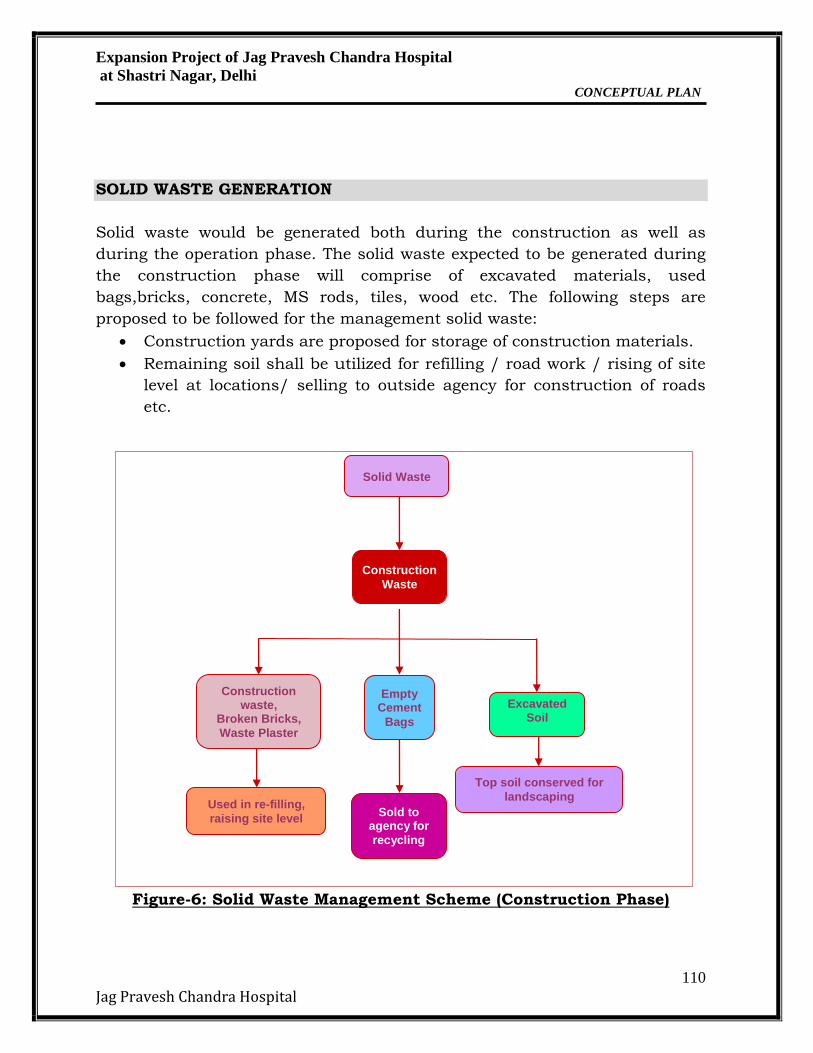
SOLID WASTE GENERATION
Solid waste would be generated both during the construction as well as
during the operation phase. The solid waste expected to be generated during
the construction phase will comprise of excavated materials, used
bags,bricks, concrete, MS rods, tiles, wood etc. The following steps are
proposed to be followed for the management solid waste:
Construction yards are proposed for storage of construction materials.
Remaining soil shall be utilized for refilling / road work / rising of site
level at locations/ selling to outside agency for construction of roads
etc.
Figure-6: Solid Waste Management Scheme (Construction Phase)
Expansion Project of Jag Pravesh Chandra Hospital
at Shastri Nagar, Delhi CONCEPTUAL PLAN
111
Jag Pravesh Chandra Hospital
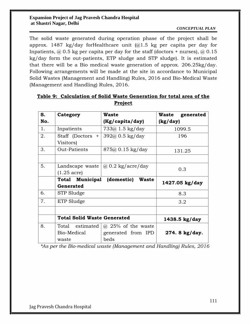
The solid waste generated during operation phase of the project shall be
approx. 1487 kg/day forHealthcare unit (@1.5 kg per capita per day for
Inpatients, @ 0.5 kg per capita per day for the staff (doctors + nurses), @ 0.15
kg/day form the out-patients, ETP sludge and STP sludge). It is estimated
that there will be a Bio medical waste generation of approx. 206.25kg/day.
Following arrangements will be made at the site in accordance to Municipal
Solid Wastes (Management and Handling) Rules, 2016 and Bio-Medical Waste
(Management and Handling) Rules, 2016.
Table 9: Calculation of Solid Waste Generation for total area of the
Project
S.
No.
Category Waste
(Kg/capita/day)
Waste generated
(kg/day)
1. Inpatients 733@ 1.5 kg/day 1099.5
2. Staff (Doctors +
Visitors)
392@ 0.5 kg/day 196
3. Out-Patients 875@ 0.15 kg/day 131.25
5. Landscape waste
(1.25 acre)
@ 0.2 kg/acre/day 0.3
Total Municipal (domestic) Waste
Generated 1427.05 kg/day
6. STP Sludge 8.3
7. ETP Sludge 3.2
Total Solid Waste Generated 1438.5 kg/day
8. Total estimated
Bio-Medical
waste
@ 25% of the waste
generated from IPD
beds
274. 8 kg/day.
*As per the Bio-medical waste (Management and Handling) Rules, 2016
Expansion Project of Jag Pravesh Chandra Hospital
at Shastri Nagar, Delhi CONCEPTUAL PLAN
112
Jag Pravesh Chandra Hospital
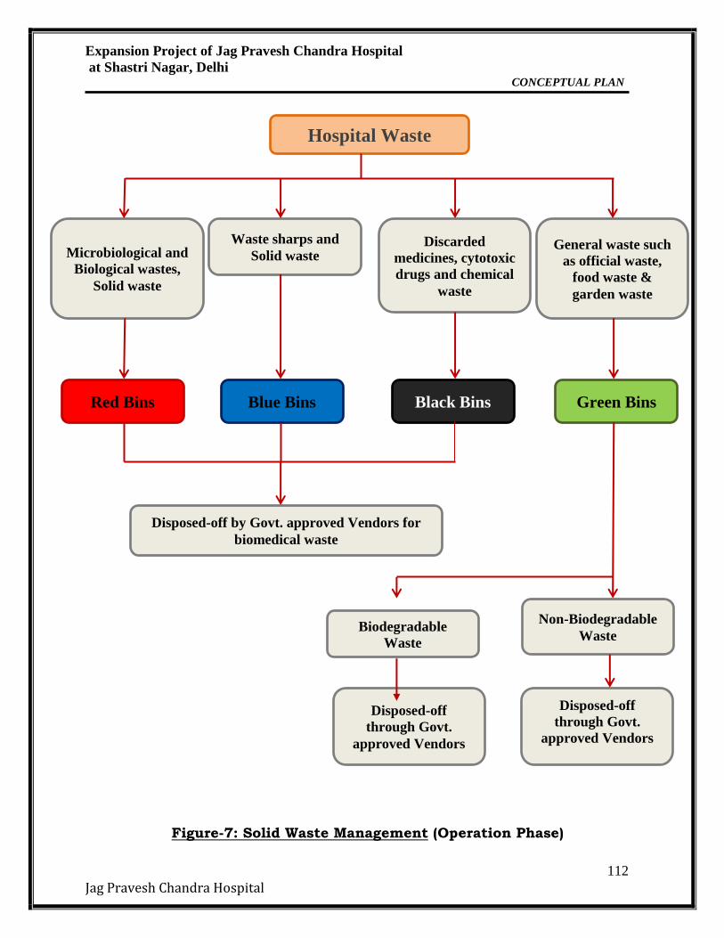
Figure-7: Solid Waste Management (Operation Phase)
Hospital Waste
Waste sharps and
Solid waste Discarded
medicines, cytotoxic
drugs and chemical
waste
General waste such
as official waste,
food waste &
garden waste
Microbiological and
Biological wastes,
Solid waste
Red Bins Blue Bins Black Bins Green Bins
Disposed-off by Govt. approved Vendors for
biomedical waste
Biodegradable
Waste
Non-Biodegradable
Waste
Disposed-off
through Govt.
approved Vendors
Disposed-off
through Govt.
approved Vendors
Expansion Project of Jag Pravesh Chandra Hospital
at Shastri Nagar, Delhi CONCEPTUAL PLAN
113
Jag Pravesh Chandra Hospital
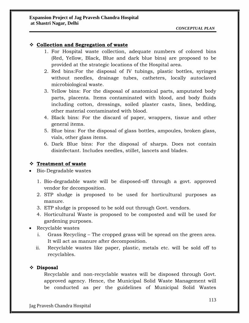
Collection and Segregation of waste
1. For Hospital waste collection, adequate numbers of colored bins
(Red, Yellow, Black, Blue and dark blue bins) are proposed to be
provided at the strategic locations of the Hospital area.
2. Red bins:For the disposal of IV tubings, plastic bottles, syringes
without needles, drainage tubes, catheters, locally autoclaved
microbiological waste.
3. Yellow bins: For the disposal of anatomical parts, amputated body
parts, placenta. Items contaminated with blood, and body fluids
including cotton, dressings, soiled plaster casts, lines, bedding,
other material contaminated with blood.
4. Black bins: For the discard of paper, wrappers, tissue and other
general items.
5. Blue bins: For the disposal of glass bottles, ampoules, broken glass,
vials, other glass items.
6. Dark Blue bins: For the disposal of sharps. Does not contain
disinfectant. Includes needles, stillet, lancets and blades.
Treatment of waste
Bio-Degradable wastes
1. Bio-degradable waste will be disposed-off through a govt. approved
vendor for decomposition.
2. STP sludge is proposed to be used for horticultural purposes as
manure.
3. ETP sludge is proposed to be sold out through Govt. vendors.
4. Horticultural Waste is proposed to be composted and will be used for
gardening purposes.
Recyclable wastes
i. Grass Recycling – The cropped grass will be spread on the green area.
It will act as manure after decomposition.
ii. Recyclable wastes like paper, plastic, metals etc. will be sold off to
recyclables.
Disposal
Recyclable and non-recyclable wastes will be disposed through Govt.
approved agency. Hence, the Municipal Solid Waste Management will
be conducted as per the guidelines of Municipal Solid Wastes
Expansion Project of Jag Pravesh Chandra Hospital
at Shastri Nagar, Delhi CONCEPTUAL PLAN
114
Jag Pravesh Chandra Hospital
(Management and Handling) Rules, 2016. Bio-Medical waste will be
disposed through the govt. approved vendors for Bio-Medical waste.
Bio-Medical waste management will be conducted as per the Bio-
Medical Waste (Management and Handling) Rules, 2016.
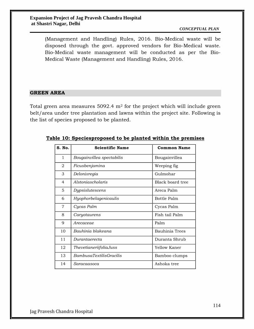
GREEN AREA
Total green area measures 5092.4 m2 for the project which will include green
belt/area under tree plantation and lawns within the project site. Following is
the list of species proposed to be planted.
Table 10: Speciesproposed to be planted within the premises
S. No. Scientific Name Common Name
1 Bougainvillea spectabilis Bougainvillea
2 Ficusbenjamina Weeping fig
3 Delonixregia Gulmohar
4 Alstoniascholaris Black board tree
5 Dypsislutescens Areca Palm
6 Hyophorbelagenicaulis Bottle Palm
7 Cycas Palm Cycas Palm
8 Caryotaurens Fish tail Palm
9 Arecaceae Palm
10 Bauhinia blakeana Bauhinia Trees
11 Durantaerecta Duranta Shrub
12 ThevetianeriifoliaJuss Yellow Kaner
13 BambusaTextilisGracilis Bamboo clumps
14 Saracaasoca Ashoka tree
Expansion Project of Jag Pravesh Chandra Hospital
at Shastri Nagar, Delhi CONCEPTUAL PLAN
115
Jag Pravesh Chandra Hospital
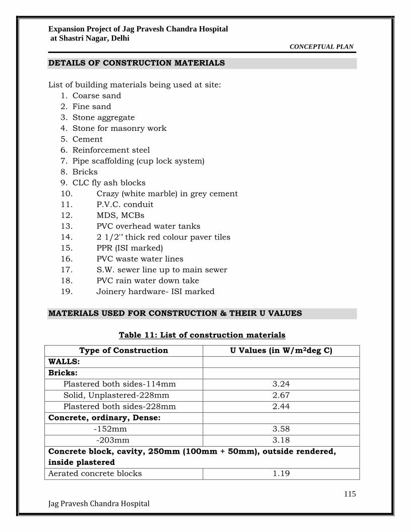
DETAILS OF CONSTRUCTION MATERIALS
List of building materials being used at site:
1. Coarse sand
2. Fine sand
3. Stone aggregate
4. Stone for masonry work
5. Cement
6. Reinforcement steel
7. Pipe scaffolding (cup lock system)
8. Bricks
9. CLC fly ash blocks
10. Crazy (white marble) in grey cement
11. P.V.C. conduit
12. MDS, MCBs
13. PVC overhead water tanks
14. 2 1/2'’ thick red colour paver tiles
15. PPR (ISI marked)
16. PVC waste water lines
17. S.W. sewer line up to main sewer
18. PVC rain water down take
19. Joinery hardware- ISI marked
MATERIALS USED FOR CONSTRUCTION & THEIR U VALUES
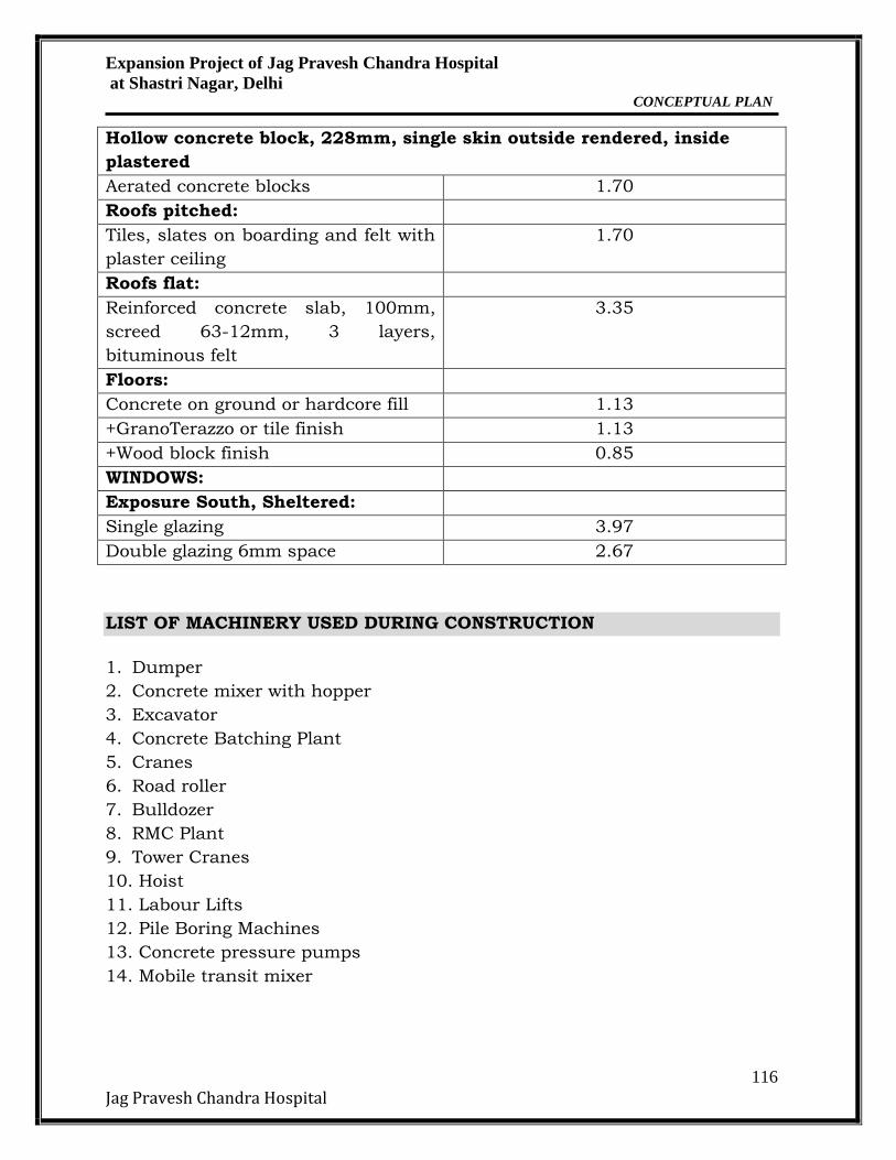
Table 11: List of construction materials
Type of Construction U Values (in W/m2deg C)
WALLS:
Bricks:
Plastered both sides-114mm 3.24
Solid, Unplastered-228mm 2.67
Plastered both sides-228mm 2.44
Concrete, ordinary, Dense:
-152mm 3.58
-203mm 3.18
Concrete block, cavity, 250mm (100mm + 50mm), outside rendered,
inside plastered
Aerated concrete blocks 1.19
Expansion Project of Jag Pravesh Chandra Hospital
at Shastri Nagar, Delhi CONCEPTUAL PLAN
116
Jag Pravesh Chandra Hospital
Hollow concrete block, 228mm, single skin outside rendered, inside
plastered
Aerated concrete blocks 1.70
Roofs pitched:
Tiles, slates on boarding and felt with
plaster ceiling
1.70
Roofs flat:
Reinforced concrete slab, 100mm,
screed 63-12mm, 3 layers,
bituminous felt
3.35
Floors:
Concrete on ground or hardcore fill 1.13
+GranoTerazzo or tile finish 1.13
+Wood block finish 0.85
WINDOWS:
Exposure South, Sheltered:
Single glazing 3.97
Double glazing 6mm space 2.67
LIST OF MACHINERY USED DURING CONSTRUCTION
1. Dumper
2. Concrete mixer with hopper
3. Excavator
4. Concrete Batching Plant
5. Cranes
6. Road roller
7. Bulldozer
8. RMC Plant
9. Tower Cranes
10. Hoist
11. Labour Lifts
12. Pile Boring Machines
13. Concrete pressure pumps
14. Mobile transit mixer