Embed Size (px)
Citation preview
Conceptual Modeling in Systems Biology FostersEmpirical Findings: The mRNA LifecycleDov Dori1*, Mordechai Choder2
1 Faculty of Industrial Engineering and Management, Technion, Israel Institute of Technology, Haifa, Israel, 2 Department of Molecular Biotechnology,Rappaport Faculty of Medicine, Technion, Israel Institute of Technology, Haifa, Israel
One of the main obstacles to understanding complex biological systems is the extent and rapid evolution of information, waybeyond the capacity individuals to manage and comprehend. Current modeling approaches and tools lack adequate capacityto model concurrently structure and behavior of biological systems. Here we propose Object-Process Methodology (OPM),a holistic conceptual modeling paradigm, as a means to model both diagrammatically and textually biological systemsformally and intuitively at any desired number of levels of detail. OPM combines objects, e.g., proteins, and processes, e.g.,transcription, in a way that is simple and easily comprehensible to researchers and scholars. As a case in point, we modeled theyeast mRNA lifecycle. The mRNA lifecycle involves mRNA synthesis in the nucleus, mRNA transport to the cytoplasm, and itssubsequent translation and degradation therein. Recent studies have identified specific cytoplasmic foci, termed processingbodies that contain large complexes of mRNAs and decay factors. Our OPM model of this cellular subsystem, presented here,led to the discovery of a new constituent of these complexes, the translation termination factor eRF3. Association of eRF3 withprocessing bodies is observed after a long-term starvation period. We suggest that OPM can eventually serve asa comprehensive evolvable model of the entire living cell system. The model would serve as a research and communicationplatform, highlighting unknown and uncertain aspects that can be addressed empirically and updated consequently whilemaintaining consistency.
Citation: Dori D, Choder M (2007) Conceptual Modeling in Systems Biology Fosters Empirical Findings: The mRNA Lifecycle. PLoS ONE 2(9): e872.doi:10.1371/journal.pone.0000872
INTRODUCTIONRecent years have witnessed unprecedented increases in the
number, variety and complexity of information resources available
to researchers in the life sciences. We are at a turning point in
biological research, where emphasis is shifting from the study of
a single molecular process to studying complete cellular pathways
and the entire cell as a system. This pivotal time for the life
sciences is captured by the words of Kitano: ‘‘a transition is occurring
in biology from the molecular level to the system level that promises to
revolutionize our understanding of complex biological regulatory systems and to
provide major new opportunities for practical application of such knowledge’’
[1]. There is now a drive to acquire system-level comprehension of
the countless pieces of information that have been gathered thanks
to decades of meticulous laboratory research by thousands of
scientists. These efforts, many of which are currently considered as
contributions to Systems Biology, are aimed at understanding the
underlying structure and behavior of biological systems at the
molecular, cellular, organism, and habitat levels. Kitano [1] also
noted that new tools, ranging from experimental devices to
software and analytical methods, are required if we are to meet the
challenges of systems biology.
Overview of the emerging systems biology fieldIn November 2006, Nature Cell Biology and Nature Reviews
Molecular Cell Biology published jointly on the Web (http://
www.nature.com/focus/systemsbiologyuserguide) Systems Biolo-
gy: a User’s Guide [2]. This is a collection of Review-type articles
concerning the most important approaches and challenges in
systems biology. The editors of the guide echo the words of
Davidson et al. [3] ‘‘systems biology is essential if we are ever to make sense
of biological complexity, as intuitive ‘conceptual’ models quickly reach their
limits beyond simple linear pathways’’. Moreover, they affirm: ‘‘The time
has come for molecular cell biologists, computer scientists and mathematicians
to embrace each other’s approaches, as is commonplace in the physical sciences.
… More importantly, there is an urgent need to make the next generation of
molecular cell biologists ‘systems savvy’. The traditional segregation in higher
education of biology from mathematics and physics presents challenges and
requires an integration of these subjects for the biologists of the future.’’ In the
Editorial, systems biology is defined broadly as the integration of
complex and highly diverse biological information into a holistic,
quantitative and predictive conceptual framework [2]. A key
notion here, as in the work of Davidson et al. [3], is the ability of
system modeling to be compatible with empirical research, but
more specifically, it is suggested that the model must foster
empirical predictions. Since systems biology is based on quanti-
tative empirical data and marries informal cartoon-like static
flowchart-type models with formal mathematical and computa-
tional modeling, it has indeed the promise of generating biological
predictions accessible to experimental verification. Moreover, the
requirement for modeling and model friendly experimentation to
work hand-in-hand, they claim, creates a dynamic interplay that
has the potential to result in cyclically better mechanistic
understanding and more rigorous interpretation of the system
under study. In line with this call to integrate modeling and
Academic Editor: Peter Fraser, The Babraham Institute, United Kingdom
Received April 18, 2007; Accepted July 30, 2007; Published September 12, 2007
Copyright: � 2007 Dori, Choder. This is an open-access article distributed underthe terms of the Creative Commons Attribution License, which permitsunrestricted use, distribution, and reproduction in any medium, provided theoriginal author and source are credited.
Funding: This work was supported by the Israel Science Foundation, founded bythe Israel Academy of Sciences and Humanities, by the Rappaport Foundation, bya grant from Paamei Tikva, by a grant from the Bernard M. Gordon Center forSystems Engineering at the Technion, and by a grant from the Elias Fund forMedical Research at the Technion.
Competing Interests: The authors have declared that no competing interestsexist.
* To whom correspondence should be addressed. E-mail: [email protected]
PLoS ONE | www.plosone.org 1 September 2007 | Issue 9 | e872
experimentation, we present a new systems biology modeling
approach that has already enabled a significant model-driven
experimental finding, which we present as part of this work.
Also in the editorial, after noting how molecular cell biology is
emancipating itself from an informal, reductive, hypothesis-driven
approach by embracing high-throughput data acquisition, rigor-
ous quantification and mathematical modeling, it is forecast by
Kritikou et al. [2] that ultimately a ‘‘virtual cell’’ will be developed.
With such an aspiration in mind, we have designed a predictive,
conceptual object-process-based model of the mRNA lifecycle. As
we demonstrate here, this model facilitates novel insights into this
integral cellular subsystem. Moreover, our model potentially
represents a new tool for modeling other biological systems.
Adopting a mechanistic view, Davidson et al. [3] contended that
traditional biological approaches, which focus on determining the
functions of one or a few genes at a time, are not adequate for
analyzing large regulatory control systems organized as networks.
The need for formal modeling is manifested, among other
requirements, by the need to express logical expressions even
when describing the expression of a single gene. For example, cis-
regulatory elements active within defined spatial limits during
development often use AND logic, in that two different
transcription factors, each present in a given spatial domain, must
be bound to the cis-regulatory DNA at once in order for
transcription to be activated. Davidson et al. [3] propose that
understanding why a given developmental process occurs requires
learning the critical inputs and outputs and their key target sites
throughout the genomic regulatory system that controls the
dynamic process, and moreover relies on experimental determi-
nation of the functional significance of each parameter. In
summary, Davidson et al. [3] argue that biological complexity
dictates the need for formal modeling, but specifically for models
that can work hand-in-hand with empirical research.
Current approaches to biological modelingThe number of interactions, processes, and transport activities in
the living cell is enormous. Therefore, often preceding a quanti-
tative problem of how much or to what extent is the qualitative
one of figuring out how and what. Thus, a combined qualitative
then quantitative conceptual modeling approach, such as the one
adopted in this work, plays a crucial role in facilitating human
comprehension of complex cellular mechanisms. Conceptual
models advocate the construction of primarily qualitative models,
in which biological concepts are put in context with each other in
an attempt to gain insights into the function, structure, and
dynamics of the biological systems under study. Once a particular,
relatively small subsystem in a specific cell location is understood
well enough, mathematical tools, such as differential equations,
can successfully describe time varying changes. In what follows we
survey briefly current approaches and software environments for
modeling biological systems, highlighting their advantages and
disadvantages.
Modeling efforts in biology are sometimes classified according to
their focus on quantitative vs. qualitative aspects. However,
oftentimes the two approaches cannot be separated; for example
understanding a qualitative process such as the mechanism
regulating cell division requires quantitative understanding of this
system’s dynamics. It must be appreciated that a complex network
of protein interactions that influence the activities of cyclin-
dependent kinases control major events of the cell cycle, including
DNA synthesis, mitosis and cell division. [4] modeled this network
using a set of nonlinear differential equations and by numerical
simulation predicted its behavior. However, like other researchers
before them, they realized that these computer simulations, despite
enabling detailed quantitative comparisons between theory and
experiment, give little insight into the qualitative dynamics of the
control system and do not reveal how molecular interactions
determine the fundamental physiological properties of cell
replication. To that end, they used bifurcation diagrams as an
analytical tool to obtain new views of the dynamic organization of
the cell cycle, the role of checkpoints in assuring the integrity of the
genome, and the abnormal regulation of cell cycle events in
mutants. They validated these insights by analyzing cell cycle
regulation in fission yeast. Here, a combined quantitative and
qualitative modeling approach is what ultimately provided
genuine insights, but this combination is likely paradigmatic.
Quantitative Models One quantitative modeling environ-
ment is E-Cell [5,6], which uses general technologies and
theoretical supports for computational biology with the grand
aim to allow for precise whole cell simulation at the molecular
level. E-cell simulates cell behavior by integrating numerically the
differential equations described implicitly by reaction rules. It
includes numerical simulations and mathematical analysis
technologies to predict, obtain or estimate parameters such as
reaction rates and concentrations of molecules in the cell. In spite
of all its capabilities, E-cell lacks the ability to specify highly
complex systems, based on qualitative data, with multiple
components.
Another example of a mathematics-oriented software modeling
environment is the Virtual Cell [7], developed for quantitative cell
biological research by the National Resource for Cell Analysis and
Modeling. Slepchenko [8] described applications of this tool to
nucleocytoplasmic transport and intracellular calcium dynamics.
The Virtual Cell software environment enables sophisticated
quantitative dynamics modeling, such as the one described in [8].
The biological to mathematical mapping allows for separate use of
biological and mathematical components, and includes automatic
mathematical simplification using pseudo-steady approximations
and mass conservation relationships. This mapping allows for
direct specification of mathematical problems, performing simula-
tions and analysis on those systems. However, like E-cell, the
Virtual Cell software environment lacks the ability to faithfully
describe complex systems that are based on qualitative results. It
also lacks the capacity to describe multiple interconnected
components that need to be modeled at various levels of detail.
Investigating multi-cellular organisms by constructing their
conceptual models has been promoted by Harel [9], who also
suggested a Turing-like test for biological modeling [10]. Formal
modeling of C. elegans development has been carried out by Kam
et al. [11] using a scenario-based approach. They have presented
preliminary results of a new approach to the formal modeling of
biological phenomena based on the language of live sequence
charts with the play-in/play-out process. Keet [12] has suggested
exploiting existing data better and bringing more structure to the
‘‘biological data anarchy’’ on the Web by enhancing biological
information systems with granularity and harnessing Semantic
Web technologies.
Some quantitative approaches combine the concept of in-
telligent computer programs, commonly known as software agents,
with mathematical models. Applying an OO and agent-based
approach, Webb and White [13] modeled and simulated
metabolic and genetic pathways. Due to limitations of the OO
paradigm that stem from its origins in the software domain, this
model includes such non-biological artifacts as capsules, ports, and
connectors that exchange messages, making it less than intuitive.
Object-Oriented and UML-based modeling approa-
ches Conceptual modeling originated with efforts to streamline
software development some three decades ago. Therefore, the
Biological Systems Modeling
PLoS ONE | www.plosone.org 2 September 2007 | Issue 9 | e872
object-oriented approach, which is the currently accepted
paradigm in the software engineering community, has been very
popular in recent years for modeling systems in general and
biological systems in particular. The object-oriented (OO)
approach advocates that objects are the prime entities or
building blocks of software systems, and this notion has been
recently extended via SysML (www.sysml.org) to systems in
general. A basic tenet of OO modeling is the encapsulation
principle, which states that objects, the basic building blocks of the
model, encapsulate (own) processes, known as methods or
operations. The latter do not have their own right of existence
as stand-alone things, making it awkward to try to model biological
processes. Cell-level biological processes usually involve a host of
input, output, and facilitating molecules of all kinds, which are the
objects. Since the OO modeling paradigm advocates that each
process be a subordinate of some object, an arbitrary choice must
be made as to which object is the owner of the process being
modeled. This enforced subordination inevitably leads to
a counter-intuitive model right from the outset.
BioUML, [14] is an open source software framework for
systems biology, which is based on Unified Modeling Language,
UML [15,16], the industry standard in software development.
UML caters to the OO paradigm in that its terminology and
notation closely follow the notions and capabilities of current OO
programming languages.
UML is built on the premise that ‘‘Modeling is the designing of
software applications before coding’’ [17]. UML-based modeling
approaches like BioUML are object-oriented, meaning that their
main building blocks are objects, which are primary static entities
that own processes. The inherent orientation of UML towards
software, its unnecessary complexity [18] and its model multiplic-
ity problems [19] cause intra- and inter-model consistency
problems [20].
In general, the current Object-Oriented approach to modeling
and developing software systems is not suitable for representing
effectively biological concepts, because, as argued, it cannot model
concurrently in a single type of diagram both the objects, e.g.,
a protein, and the processes, e.g., transcription, that transform
(create, consume, or change the state of) these objects. UML 2.0
[16], for example, includes 13 different types of models, each with
its own diagram type, separate set of symbols and concepts.
Moreover, the lack of the process as a stand-alone concept in the
OO modeling approach is a major hindrance for modeling
biological systems, which are mostly process-intensive. Finally,
many software engineers find it difficult to master the UML
modeling framework, making it unrealistic to expect biologists to
employ it in a valuable way to model biological systems.
Systems Biology Markup Language, SBML [21] is an open,
XML-based format for representing biochemical reaction net-
works and describing models common to research in many areas
of computational biology, including cell signaling pathways,
metabolic pathways, and gene regulation. SBML data objects
use a graphical notation based upon UML, which in turn is
translated into XML. CellML [22] is another XML-based
language for storage, sharing, exchange, and reuse of computer-
based mathematical models. It includes information about model
structure, equations describing processes, and metadata to search
for model components.
The recent Systems Modeling Language, SysML [23] initiative
offers no solutions to the problems of current OO approaches to
modeling, as it is based on UML and therefore suffers from most of
UML’s deficiencies, namely multiple diagram types and segrega-
tion between structure and behavior.
Specialized modeling frameworks Kohn [24] has pro-
posed a graphical method for mapping bioregulatory networks and
representing multimolecular complexes, protein modifications,
and actions at cell membranes and between protein domains. The
symbol conventions, defined for these molecular interaction maps,
accommodate multiprotein assemblies and protein modifications
and thus can generate combinatorially large numbers of molecular
species. However, most of the 20 or so pictogram symbols are
highly specialized. For example, one of them is defined as
‘‘Transport of Protein A from cytosol to nucleus’’. Clearly, this
method is limited to modeling very specific systems.
In general, when considering human-readable diagrammatic
representations, it is notable that the current informal ways most
biologists draw diagrams means that correct biological interpre-
tation depends entirely on the reader’s knowledge [25]. Kitano et
al. [26] recount examples where an arrow symbol has four
different potential interpretations and indicate rightly that such
ambiguities become a major problem as the size and complexity of
the system increases, highlighting the need for formality to avoid
ambiguity. Process diagrams proposed by [25] that make use of
CellDesigner [26] are state transition-based.
Using different arrowhead shapes CellDesigner diagrams focus
on conveying the semantics of several process types prevalent in
signaling, such as translocation, catalysis, splitting, phosphoryla-
tion, or state transition. Formalized process diagrams have been
used to describe signal-transduction cascades and pathway maps,
and are readable and precise as long as the network is not too
large. However, scalability is an issue. There is no way to refine
mechanisms and designating new pictograms for each new
reaction type is problematic. Moreover, as Blinov et al. [27]
observe, because process diagrams require explicit representation
of all the species (which in our ontology are referred to as objects)
at some level, they omit the vast majority of species and reactions,
which are processes in our ontology, that could potentially be
generated during signaling.
In an attempt to solve this problem, Blivnov et al. have introduced
graphical rules to allow the connectivity of proteins in a complex to
be represented explicitly. These rules provide a means to visualize
comprehensibly protein-protein interactions. Nevertheless, for more
general biological modeling, process maps are likely to be of
unmanageable size due to combinatorial complexity.
An example of a combined quantitative-qualitative model is the
work of Tyson et al. [28], who modeled the dynamics of cell cycle
regulation. They applied a systems dynamics-based approach and
bifurcation diagrams to provide a new perspective on cell cycle
checkpoints and mutant phenotypes in fission yeast. In this model,
qualitative changes can occur, for example, when a stable steady
state loses its stability or even ceases to exist and is replaced by an
oscillatory solution. Such an event is in the nature of the recurrent
solutions of a dynamic system and is necessary for a model
attempting to characterize the cell cycle. These qualitative
changes, called bifurcations, happen at specific values of the
parameters termed bifurcation points and are described by a one-
parameter bifurcation diagram. These are two-dimensional
graphs, where each axis shows some quantity and the quantitative
analysis yields certain meaningful qualitative results, such as the
G1, G2, or metaphase checkpoints in the fission yeast cell cycle.
BioTapestry [29] is the latest interactive tool for building,
visualizing, and simulating genetic regulatory networks. It is designed
around the concept of a developmental network model, intended to
handle large scale models and represent systems that exhibit
increasing complexity over time. The system supports data generated
by perturbing the expression of specific genes, portrays views of the
network during development, and lays out network models.
Biological Systems Modeling
PLoS ONE | www.plosone.org 3 September 2007 | Issue 9 | e872
Problems with current models The current state of affairs,
reflected in this survey, is that there are quite a number of
modeling approaches and software environments for modeling
biological systems, but many of them are object-oriented,
hindering direct and explicit process modeling, which is at the
heart of systems biology. Moreover, since most approaches are
non-scalable and specialized for specific types of cellular reactions
or subsystems, they cannot be extended naturally to modeling the
entire cell, not to mention organisms, societies, habitats and
ecologies.
Perhaps most importantly, according to the definition of systems
biology, models are supposed to advance research, yet none of the
existing modeling approaches or systems have been shown to
promote innovative questions that trigger experiments to confirm
or refute assumptions emerging from the model. Such a disap-
pointing situation indicates that a totally different modeling
approach is in order. This situation was a major stimulus for the
work presented here, a non-traditional conceptual modeling
approach that has already stimulated a new empirical finding
concerning the mRNA lifecycle.
Our approach to biological modeling Representing the
vast amount of ever increasing knowledge formally, yet accessibly,
can be compared to putting the pieces of a gigantic puzzle
together, mandating adoption of a common evolving grand model.
The model needs to be founded on a compact generic set of the
most basic ontological building blocks in order for it to be general
enough to serve as a basis for modeling the gamut of biological
systems, from molecules to ecosystems.
We submit that stateful objects and processes that transform
them, along with several types of links, as advocated by OPM—
Object-Process Methodology [30], constitute a mandatory and
sufficient set of ontological building blocks to enable conceptual
modeling of biological systems with various scales and complex-
ities. Moreover, such building blocks allow reasoning that links
theory with empiricism. We envision an OPM-based comprehen-
sive shared Web-accessible modeling framework of the entire cell,
which, if and when created, would enable the evolution of state-of-
the-art knowledge in biology. This model will keep pace with the
rapid evolution of knowledge, and will be revised constantly and
updated with new findings and conjectures.
In the present study we aimed to carry out a modest first step
toward this admittedly ambitious goal. As the yeast mRNA life
cycle is a key cellular system, we chose it to be our case in point for
conceptual modeling that employs Object-Process Methodology.
In the next section we explain in more detail why we chose Object-
Process Methodology, OPM.
Object-Process Methodology Object-Process Methodology,
OPM [30] is a holistic approach to the study and development of
complex systems that caters to human intuition while maintaining
a formal framework. The living cell is a prime example of a highly
complex system, in which the two main system aspects—structure
and behavior—are highly intertwined and hard to separate.
Motivated by the requirement of a single model to represent these
two major system aspects, OPM is founded upon two elementary
building blocks—objects and processes—which represent con-
currently the system’s structure, i.e., the objects, or components,
that comprise the system, and behavior, i.e., the processes that
transform the system’s objects by creating them, consuming them,
or changing their states, in a balanced way without highlighting
one at the expense of the other.
The elements of OPM ontology are entities and links. A
complete list of OPM elements with their symbols and definitions
is provided in Table S1. Entities, the basic building blocks of any
system modeled using OPM, are of three types: objects, possibly
with states (stateful objects), and processes. An object is a thing that
exists, possibly in some state, while a process is a thing that can
transform objects. More specifically, a process is a thing that
transforms objects, namely creates one or more objects, consumes
one or more objects, or changes the state of one or more objects.
Examples of biological objects are Protein, Cell, and Organism,
and examples of biological processes are Cleavage, Mitosis, and
Birth.
A link can be structural or procedural. A structural link
expresses a static, time-independent relation between pairs of
entities. The four fundamental structural relations are: aggrega-
tion-participation, generalization-specialization, exhibition-char-
acterization, and classification-instantiation. An example of using
the aggregation-participation structural relation is derived from
the phrase ‘‘The eukaryotic cytoskeleton is composed of micro-
filaments, intermediate filaments and microtubules.’’ (http://en.
wikipedia.org/wiki/Cell_(biology)#Subcellular_components) In
OPM, this statement is interpreted such that the Eukaryotic
Cytoskeleton is the aggregating object, the whole, which consists of
the three objects which are parts of the Eukaryotic Cytoskeleton,
each being a set of objects: the Microfilaments Set, the
Intermediate Filaments Set, and the Microtubules Set. Unidirec-
tional and bidirectional tagged structural links enable creation of
additional user-defined links with specified semantics. A pro-
cedural link connects entities (objects, processes, and states) to
describe the behavior of a system. The behavior is manifested in
three major ways: (1) a process can transform (generate, consume, or
change the state of) one or more objects; (2) an object can enable
one or more processes without being transformed by them, in
which case it acts as an enabler, i.e., a human agent or an inanimate
instrument; and (3) entities can trigger events that invoke processes if
some conditions are met. Accordingly, a procedural link can be
a transformation link, an enabling link, or an event link. A
transformation link expresses object transformation, i.e., object
consumption, generation, or state change. An enabling link expresses
the need for a (possibly state-specified) object to be present in order
for the enabled process to occur. The enabled process does not
transform the enabling object. An event link connects a triggering
entity (object, process, or state) with a process that it invokes.
The Gene-Ontology (GO) [31] project sets out to provide
a defined, universal vocabulary for describing gene and gene
product attributes in any organism. The three organizing
principles of GO are cellular component, biological process, and
molecular function. A comparison between GO principles and
OPM entities is useful as it emphasizes the advantages of OPM
ontology. A cellular component corresponds to an OPM object
and a biological process corresponds to an OPM process.
However, molecular function does not have a clear OPM
equivalent. According to the definition of process in [31],
a biological process is a ‘‘series of events accomplished by one or
more ordered assemblies of molecular functions.’’ Examples
include signal transduction and alpha-glucoside transport. A GO
molecular function ‘‘describes activities, such as catalytic or
binding activities, that occur at the molecular level.’’ Examples
include catalytic activity, binding, or adenylate cyclase activity.
Problems with this definition for molecular function are admitted
in [31], ‘‘It can be difficult to distinguish between a biological
process and a molecular function, but the general rule is that
a process must have more than one distinct step.’’ We contend that
any ontology that lacks precise, clear-cut definitions, and relies on
examples as part of the definition, is problematic. What is the
meaning of step? Is it identical to function, and if so, is function in
turn identical to activity? If so–why use so many terms, and if not,
how do they differ? Indeed, it is unclear how to differentiate
Biological Systems Modeling
PLoS ONE | www.plosone.org 4 September 2007 | Issue 9 | e872
between GO functions and GO processes. OPM takes another
approach where it does not distinguish between simple and
complex processes, just as it does not distinguish between simple
and complex objects. For example the GO molecular function
‘‘pre-mRNA 39-splice site binding’’ (taken from the actual GO file)
in OPM ontology is the OPM process of binding of the cellular
component (OPM object) ‘‘pre-mRNA 39-splice site’’, which
changes that object from state unbound to state bound. We
advocate that the OPM ontology is more precise and intuitive.
Two semantically equivalent modalities, one graphic and the
other textual, are used to describe each OPM model. A set of
inter-related Object-Process Diagrams (OPDs), showing portions
of the system at various levels of detail, constitute the graphical,
visual OPM formalism. Each OPM element is denoted by a symbol
in an OPD, and the OPD syntax specifies correct and consistent
ways by which entities can be connected via structural and
procedural links, such that each legal entity-link-entity combina-
tion bears specific, unambiguous semantics. OPCAT [32] is
a software environment that supports OPM-based system
modeling and evolution.
The Object-Process Language (OPL), which is the textual
counterpart of the graphical OPD, is a dual-purpose language,
oriented towards humans as well as machines. Catering to human
needs, OPL is designed as a subset of English, which serves
domain experts (e.g., biologists) and system architects, engaged
jointly in modeling a complex system. Every OPD construct is
expressed by a semantically equivalent OPL sentence or phrase.
According to the modality principle of the cognitive theory of
multimodal learning [33], this dual graphic/textual representation
of the OPM model increases the human processing capability.
Indeed, it has been our experience that human understanding of
the OPM model is enhanced by the convenient opportunity of
reflecting upon both the graphic and textual model representa-
tions, whereby what is missed in one modality can be grasped
when considering the other one.
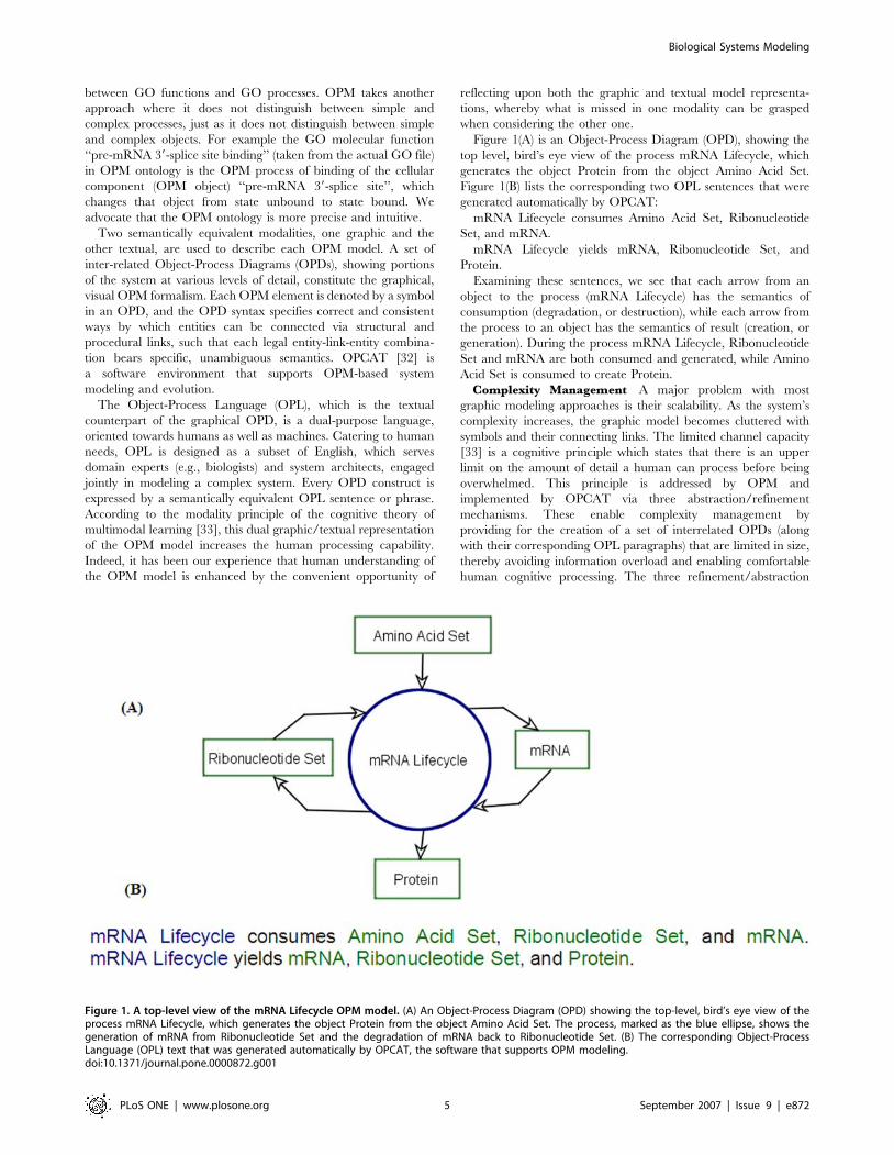
Figure 1(A) is an Object-Process Diagram (OPD), showing the
top level, bird’s eye view of the process mRNA Lifecycle, which
generates the object Protein from the object Amino Acid Set.
Figure 1(B) lists the corresponding two OPL sentences that were
generated automatically by OPCAT:
mRNA Lifecycle consumes Amino Acid Set, Ribonucleotide
Set, and mRNA.
mRNA Lifecycle yields mRNA, Ribonucleotide Set, and
Protein.
Examining these sentences, we see that each arrow from an
object to the process (mRNA Lifecycle) has the semantics of
consumption (degradation, or destruction), while each arrow from
the process to an object has the semantics of result (creation, or
generation). During the process mRNA Lifecycle, Ribonucleotide
Set and mRNA are both consumed and generated, while Amino
Acid Set is consumed to create Protein.
Complexity Management A major problem with most
graphic modeling approaches is their scalability. As the system’s
complexity increases, the graphic model becomes cluttered with
symbols and their connecting links. The limited channel capacity
[33] is a cognitive principle which states that there is an upper
limit on the amount of detail a human can process before being
overwhelmed. This principle is addressed by OPM and
implemented by OPCAT via three abstraction/refinement
mechanisms. These enable complexity management by
providing for the creation of a set of interrelated OPDs (along
with their corresponding OPL paragraphs) that are limited in size,
thereby avoiding information overload and enabling comfortable
human cognitive processing. The three refinement/abstraction
Figure 1. A top-level view of the mRNA Lifecycle OPM model. (A) An Object-Process Diagram (OPD) showing the top-level, bird’s eye view of theprocess mRNA Lifecycle, which generates the object Protein from the object Amino Acid Set. The process, marked as the blue ellipse, shows thegeneration of mRNA from Ribonucleotide Set and the degradation of mRNA back to Ribonucleotide Set. (B) The corresponding Object-ProcessLanguage (OPL) text that was generated automatically by OPCAT, the software that supports OPM modeling.doi:10.1371/journal.pone.0000872.g001
Biological Systems Modeling
PLoS ONE | www.plosone.org 5 September 2007 | Issue 9 | e872
mechanisms are: (1) unfolding/folding, which is used for refining/
abstracting the structural hierarchy of a thing and is applied by
default to objects; (2) in-zooming/out-zooming, which exposes/hides
the inner details of a thing within its frame and is applied primarily
to processes; and (3) state expressing/suppressing, which exposes/hides
the states of an object.
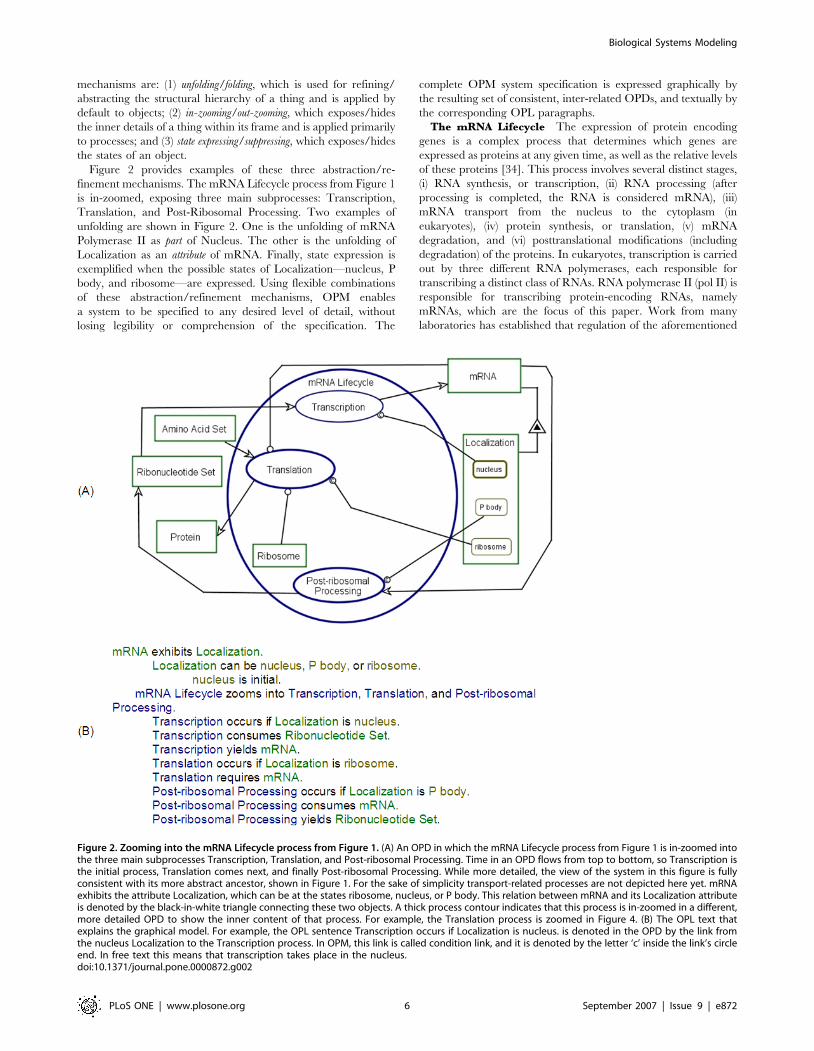
Figure 2 provides examples of these three abstraction/re-
finement mechanisms. The mRNA Lifecycle process from Figure 1
is in-zoomed, exposing three main subprocesses: Transcription,
Translation, and Post-Ribosomal Processing. Two examples of
unfolding are shown in Figure 2. One is the unfolding of mRNA
Polymerase II as part of Nucleus. The other is the unfolding of
Localization as an attribute of mRNA. Finally, state expression is
exemplified when the possible states of Localization—nucleus, P
body, and ribosome—are expressed. Using flexible combinations
of these abstraction/refinement mechanisms, OPM enables
a system to be specified to any desired level of detail, without
losing legibility or comprehension of the specification. The
complete OPM system specification is expressed graphically by
the resulting set of consistent, inter-related OPDs, and textually by
the corresponding OPL paragraphs.
The mRNA Lifecycle The expression of protein encoding
genes is a complex process that determines which genes are
expressed as proteins at any given time, as well as the relative levels
of these proteins [34]. This process involves several distinct stages,
(i) RNA synthesis, or transcription, (ii) RNA processing (after
processing is completed, the RNA is considered mRNA), (iii)
mRNA transport from the nucleus to the cytoplasm (in
eukaryotes), (iv) protein synthesis, or translation, (v) mRNA
degradation, and (vi) posttranslational modifications (including
degradation) of the proteins. In eukaryotes, transcription is carried
out by three different RNA polymerases, each responsible for
transcribing a distinct class of RNAs. RNA polymerase II (pol II) is
responsible for transcribing protein-encoding RNAs, namely
mRNAs, which are the focus of this paper. Work from many
laboratories has established that regulation of the aforementioned
Figure 2. Zooming into the mRNA Lifecycle process from Figure 1. (A) An OPD in which the mRNA Lifecycle process from Figure 1 is in-zoomed intothe three main subprocesses Transcription, Translation, and Post-ribosomal Processing. Time in an OPD flows from top to bottom, so Transcription isthe initial process, Translation comes next, and finally Post-ribosomal Processing. While more detailed, the view of the system in this figure is fullyconsistent with its more abstract ancestor, shown in Figure 1. For the sake of simplicity transport-related processes are not depicted here yet. mRNAexhibits the attribute Localization, which can be at the states ribosome, nucleus, or P body. This relation between mRNA and its Localization attributeis denoted by the black-in-white triangle connecting these two objects. A thick process contour indicates that this process is in-zoomed in a different,more detailed OPD to show the inner content of that process. For example, the Translation process is zoomed in Figure 4. (B) The OPL text thatexplains the graphical model. For example, the OPL sentence Transcription occurs if Localization is nucleus. is denoted in the OPD by the link fromthe nucleus Localization to the Transcription process. In OPM, this link is called condition link, and it is denoted by the letter ‘c’ inside the link’s circleend. In free text this means that transcription takes place in the nucleus.doi:10.1371/journal.pone.0000872.g002
Biological Systems Modeling
PLoS ONE | www.plosone.org 6 September 2007 | Issue 9 | e872
stages of pol II-mediated gene expression is coordinated [35].
Thus, in order to understand the expression of protein-encoding
genes we need to consider the entire multi-stage process, as each
stage can be regarded as a subdivision of a continuous gene
expression process. Correctly and accurately specifying this
complex process is a formidable task, beyond the realms of free
text. Clearly, it calls for the use of an appropriate modeling
language and methodology.
Transcription by pol II, the first stage in the expression of
protein-encoding genes, produces RNA–the primary transcript.
This primary transcript is processed to yield an mRNA (usually
shorter than the primary transcript) that contains a 59 cap
(m(7)GpppN) and 39 poly(A) tail. These two tags are critical for the
appropriate function, localization and stability of the mRNA [34].
Following its synthesis in the nucleus, the mRNA is transported to
the cytoplasm, where it is recognized by ribosome(s)-the protein
synthesis machinery. The mRNA is then used as a template for
translation into protein, the amino acid sequence of which is
related to the nucleotide sequence of the mRNA [34]. The last
stage of the mRNA lifecycle in the cytoplasm is its decay, which is
carried out by an array of decay factors [36,37]. Each one of the
stages described above is tightly regulated. Once produced, the
mRNA is the key target in the regulation of the gene expression,
referred to as post-transcriptional regulation. One aspect of post-
transcriptional regulation is at the level of mRNA localization
within the cell, for example nuclear vs. cytoplasmic localization.
Recently, a new venue for mRNA localization was uncovered
that revolutionized our view of how gene expression is regulated
post-transcriptionally. Specifically, yeast mRNA can be localized
in discrete cytoplasmic foci together with a number of mRNA
decay factors and limited repertoire of translation factors, mostly
translation repressors. These foci, termed processing bodies (P
bodies), represent complexes where mRNA degradation can
occur, since mRNA decay intermediates [38] and many factors
of the major mRNA decay pathway reside in P bodies [38–49].
The discovery of P bodies in yeast and related bodies in higher
eukaryotes, e.g., dcp bodies, GW bodies, brings the spatial control
of macromolecule to the focus of our attention.
A different kind of cytoplasmic foci, referred to as stress
granules, have been discovered in higher eukaryotes under various
stress conditions (recently reviewed in [49,50]). Unlike P bodies,
these foci contain several translation factors, but not the ribosomal
large subunit [51,52]. Stress granules are believed to be sites where
non-translating mRNA resides during stress conditions [53].
Association of mRNAs with stress granules was proposed to
represent a mechanism for translational repression. This kind of
repression can be reversible, as the mRNA can be transported
back to the ribosome when conditions favor translation. Anderson
and Kedersha [54] proposed that mRNAs in stress granules are
subjected to triage: first they are monitored for integrity and
composition, and then they are sorted for productive translational
initiation or targeted to degradation. In addition, it has been
suggested that stress granules may communicate with P bodies
when sorting the mRNA for degradation [55]. In yeast, the
organism under study here, no stress granules have been identified
and the bulk of known P bodies do not contain translation factors
[43]. Recently, work from Parker’s group has revealed that
mRNAs in the yeast P bodies are not necessarily degraded, but
rather can be transported to the ribosome for translation [56].
Thus, yeast P bodies may have dual function, carrying out the
functions of both mammalian P bodies and stress granules.
Most published works to date have used fluorescent microscopy
to study P bodies or stress granules. This technology allows the
detection of large complexes whose fluorescence is above that of
the background, but small P bodies might escape detection.
Interestingly, though, Aragon et al. [57] have recently reported
that mRNAs in starved yeast cells are sequestered in proteinatious
complexes and therefore resist standard extraction procedures.
These mRNAs could be recovered by disrupting the complexes
with proteases. The released mRNA can then be analyzed using
whole genome technology. The authors proposed a plausible
model in which the protecting complexes are P bodies [57]. If
proved correct, the differential mRNA extraction technique will
allow analyzing even small P bodies and also obtain, for the first
time, quantitative results at the organism level.
It has been contended both for yeast [38,54,55] and higher
eukaryotes [48,56] that there is frequent shuttling of mRNA
between the ribosome (or poly-ribosome) and these cytoplasmic
bodies. Moreover, it has been suggested that two of the
cytoplasmic structures, i.e., the ribosome, which activates trans-
lation, and the P body, which represses it, compete for mRNA.
The outcome of this competition determines mRNA translatability
and hence protein synthesis [58]. To demonstrate shuttling of
mRNA between these two complexes, investigators utilized
specific drugs. Drugs that block mRNAs within the ribosomes
cause P bodies to disassemble, whereas drugs or mutations that
compromise mRNA loading onto the ribosomes enhance the
assembly of P bodies [38,48,54,50,59]. Such studies reveal that P
bodies are dynamic structures, for their mass varies as the mRNA
is transported back and forth between P bodies and ribosomes. It
has also become clear that the balance between these two sub-
cytoplasmic compartments, and hence the P bodies’ size, is
responsive to environmental signals [43,48,54,58]. Thus, external
signals, such as starvation, UV irradiation, or changes in
osmolarity, can trigger mRNA redistribution between the two
compartments. It was the complexity and intricacy of processes
constituting the mRNA lifecycle, outlined above, which triggered
our realization that conceptual modeling might likely contribute to
understanding this particular cellular sub-system. Moreover, we
anticipated that the modeling should raise empirically addressable
questions, the answers to which would help researchers compre-
hend better mRNA biology. Indeed, the modeling activity has
raised at least one research question, the localization of eRF3 in P
bodies, which we have confirmed experimentally.
METHODSOPM allows us to model the system under study—the mRNA
lifecycle—at various hierarchically arranged levels of detail. We
started modeling only established knowledge concerning the
mRNA lifecycle. Figure 1A is the System Diagram (SD). It is the
top level Object-Process Diagram (OPD), which provides a bird’s
eye view of the system, illustrating graphically the mRNA Lifecycle
system in a nutshell. In the mRNA Lifecycle process, Ribonucle-
tides are consumed to generate mRNA. mRNA is produced by the
Synthesis process, which, as the model’s next levels of detail
reveals, includes Transcription and Nucleo-cytoplasmic Trans-
port. The main product of the mRNA Lifecycle process is Protein,
which is synthesized during the Translation process. Stages that
follow Translation take place in the P bodies and might produce
Ribonucletides, as detailed below. To complete the lifecycle, one
option that occurs following translation (see below) is that the
mRNA is decomposed back into its constituent Ribonucletides.
Figure 1(B) is the automatically generated textual description,
called Object-Process Language (OPL), expressing what the
Object-Process Diagram (OPD) shown in Figure 1(A) tells us
graphically. This OPL paragraph, a collection of OPL sentences,
is equivalent in its informational content to its corresponding
OPD.
Biological Systems Modeling
PLoS ONE | www.plosone.org 7 September 2007 | Issue 9 | e872
RESULTSFigure 2(A) shows an OPD in which the mRNA Lifecycle process
from Figure 1 is zoomed in to expose its three main sub-processes,
Transcription, Translation, and Post-ribosomal Processing. This
enables us to visualize the details of the mRNA Lifecycle process.
The convention is that within an in-zoomed process, there is
a timeline—the Y axis of the diagram—that flows from the top of
the in-zoomed process ellipse to its bottom. Accordingly,
Transcription happens first, followed by Translation, and finally
the Post-ribosomal Processing takes place. Parallel or alternative
processes are depicted at the same height. Cycles and loops are
easily expressed, and the mRNA cycle as a whole is an example.
As discussed in the introduction, an important feature of the
mRNA Lifecycle is the Localization of the mRNA, which we
model as an attribute of mRNA (indicated by the black-inside-
white triangle link), with each Localization state being a concrete
localization. It is common knowledge that mRNA is produced in
the nucleus and then transported to the cytoplasm, where it is
translated and degraded [34].
In the cytoplasm, mRNA can be located in various complexes,
such as the ribosome or P body. It is quite possible that the yeast
cytoplasm contains other large bodies that accommodate mRNA.
However, as such bodies have not been reported, the only two
cytoplasmic mRNA locations in our model are the ribosome
(including also poly-ribosome) and P bodies. It has not been
established whether mRNA can move in the cytoplasmic matrix,
unattached to any complex. Trying to include this option in our
initial model rendered the model more complex with no tangible
benefit. Following Occum’s Razor, we therefore assumed the
simplest option, i.e., that mRNA does not reside in the cytoplasmic
matrix as an unbound molecule. Thus, Figure 1(A) shows only
three mRNA Localization states: nucleus, P body, and
ribosome. Interestingly, when only these three mRNA Localiza-
tion states are considered, a question arises regarding what is the
first cytoplasmic location of mRNA after it is transported from
the nucleus.
The model leaves only two options: either ribosome or P body.
Although ribosomes have been implicated as the mRNA acceptor
in the cytoplasm [59], an as yet unconsidered possibility raised by
this model is that in some cases a P body can be the first
cytoplasmic location for mRNA. Indeed, Jean Marx has noted that
P bodies are found around the nucleus [60]. The conjecture that P
bodies may be the first cytoplasmic location for mRNA illustrates
the utility and the value of a formal, expressive conceptual
modeling approach in provoking new ideas and viewpoints. As we
show below, our modeling framework indeed triggered an
experiment that provided new, significant information related to
the mRNA lifecycle.
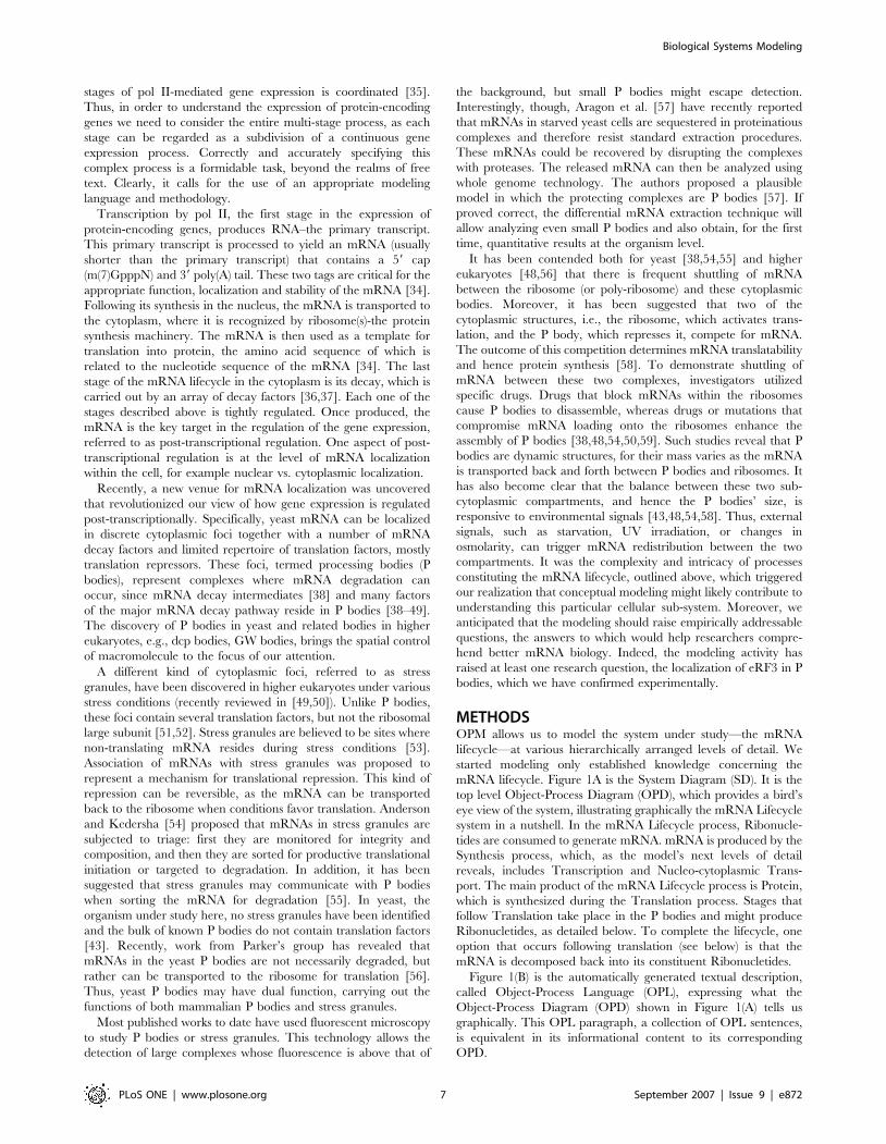
Figure 3 shows a refinement of the mRNA lifecycle OPM model
of Figure 2, in which three mRNA Transport processes, marked in
cyan, have been added: Nucleo-cytoplasmic Transport, P Body-
Ribosome Transport, and Ribosome-P body Transport. Accord-
ing to our model, the cytoplasmic mRNA is localized either in the
Ribosome or in the P body. The Nucleo-cytoplasmic Transport,
which requires three factors, eIF Set, Dhh1p, and Pat1p, changes
the Localization of the mRNA from nucleus to P body. A pair of
input/output links, the cyan and purple arrows, denote this
transport. The two other transport processes are the inverse of
each other: P Body-Ribosome Transport changes the Localization
of the mRNA from P body to ribosome and induces translation
initiation, while Ribosome-P body Transport does the opposite,
repressing translation. As in the Nucleo-cytoplasmic Transport, for
Figure 3. Adding the mRNA transport processes. (A) Three mRNA transport processes, marked in cyan, have been added to the OPD of Figure 2:Nucleo-cytoplasmic Transport, P Body-Ribosome Transport, and Ribosome-P body Transport. According to our model, the cytoplasmic mRNA islocalized either in the ribosome or in the P bodies. For simplicity, possible transport from the nucleus to the ribosome is not modeled here. Therefore,the Nucleo-cytoplasmic Transport changes the Localization of the mRNA from nucleus to P body. The two other transport processes are the inverse ofeach other: P Body-Ribosome Transport, which changes the Localization of the mRNA from P body to ribosome, while Ribosome-P body Transport,which does the opposite. (B) The sentences of the OPL paragraph listing the processes and objects into which mRNA Lifecycle zooms and how eachtransport process changes the value of the Localization attribute of mRNA between nucleus, P body, and ribosome.doi:10.1371/journal.pone.0000872.g003
Biological Systems Modeling
PLoS ONE | www.plosone.org 8 September 2007 | Issue 9 | e872

each of these two transport processes there is a pair of input/
output links, the cyan and purple arrows. If we follow the sequence
of these alternating input/output links (cyan and purple arrows),
we get that the Localization of mRNA, which starts at the nucleus,
changes to P body and then to ribosome. This can be followed by
alternating between ribosome and P body, possibly many times,
until the mRNA is consumed (degraded) by the Post-ribosomal
Processing, as indicated by the consumption link—the arrow in
Figure 3 from mRNA to that process. As discussed in the
Introduction, dynamic transport of mRNAs between the two
compartments has been proposed, but little is known about the
transport mechanism, in particular, whether it is direct or involves
the cytoplasmic matrix. This black box is yet another example of
a model-triggered potential area of research. Two mRNA Decay
Factors, Pat1p and Dhh1p, are implicated in the transport of
mRNA from the ribosome to the P bodies [54]. These two factors
are therefore depicted as instruments that enable the Ribosome-P
body Transport process.
In Figure 4, the Translation process is in-zoomed, exposing its
three subprocesses: Elongation, Termination, and Protein Clea-
vage&Releasing, which are executed in this order. Translation
initiation is depicted in Figure 3 as P Body-Ribosome Transport.
The corresponding factors involved as instruments in these
processes are also shown linked to the processes with an
instrument link (a line ending with a circle at the process end).
The object eEF Set is the instrument for the Elongation process,
while eRF Set with its members, the factors eRF1 and eRF3, is the
instrument for the Protein Cleavage&Releasing process.
eRF3 is an instrument for translation termination (see [61] and
references therein), which has also been shown to be involved in
mRNA decay [62–64]. These observations provoked us to propose
that eRF3 helps coupling between translation termination and P
body assembly by serving as an instrument for the Ribosome-P
body Transport process. Our model predicts that eRF3 is
transported together with the mRNA to P bodies. Indeed, eRF3
is associated with mRNP [63,64].
Figure 4. Zooming into the Translation process. (A) Zooming into the Translation process exposes its three subprocesses that follow P Body-Ribosome Transport (initiation): Elongation, Termination, and Protein Cleavage&Releasing. The corresponding factors involved as instruments inthese processes are also shown linked to the processes with an instrument link (a line ending with a circle at the process end). The object eEF Set isthe instrument for the Elongation process, while eRF Set with its members, the factors eRF1 and eRF3, is the instrument for the ProteinCleavage&Releasing process. Our conjecture is that eRF3 is the factor which is also involved as instrument for the Ribosome-P body Transportprocess. Since there is no proof for this as yet, the instrument link from eRF3 to Ribosome-P body Transport is colored red, denoting uncertainty. (B)The OPL text of the OPD in (A). Note that the word requires in the OPL sentence Ribosome-P body Transport requires eRF3. denotes the sameuncertainty regarding the role of eRF3 as instrument to the Ribosome-P body Transport process, analogous to the instrument link from eRF3 toRibosome-P body Transport in (A).doi:10.1371/journal.pone.0000872.g004
Biological Systems Modeling
PLoS ONE | www.plosone.org 9 September 2007 | Issue 9 | e872
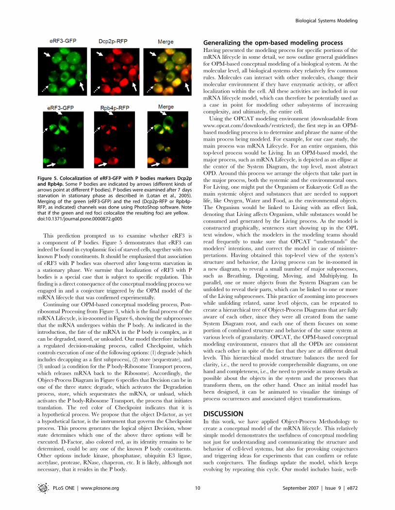
This prediction prompted us to examine whether eRF3 is
a component of P bodies. Figure 5 demonstrates that eRF3 can
indeed be found in cytoplasmic foci of starved cells, together with two
known P body constituents. It should be emphasized that association
of eRF3 with P bodies was observed after long-term starvation in
a stationary phase. We surmise that localization of eRF3 with P
bodies is a special case that is subject to specific regulation. This
finding is a direct consequence of the conceptual modeling process we
engaged in and a conjecture triggered by the OPM model of the
mRNA lifecycle that was confirmed experimentally.
Continuing our OPM-based conceptual modeling process, Post-
ribosomal Processing from Figure 3, which is the final process of the
mRNA Lifecycle, is in-zoomed in Figure 6, showing the subprocesses
that the mRNA undergoes within the P body. As indicated in the
introduction, the fate of the mRNA in the P body is complex, as it
can be degraded, stored, or unloaded. Our model therefore includes
a regulated decision-making process, called Checkpoint, which
controls execution of one of the following options: (1) degrade (which
includes decapping as a first subprocess), (2) store (sequestrate), and
(3) unload (a condition for the P body-Ribosome Transport process,
which releases mRNA back to the Ribosome). Accordingly, the
Object-Process Diagram in Figure 6 specifies that Decision can be in
one of the three states: degrade, which activates the Degradation
process, store, which sequestrates the mRNA, or unload, which
activates the P body-Ribosome Transport, the process that initiates
translation. The red color of Checkpoint indicates that it is
a hypothetical process. We propose that the object D-factor, as yet
a hypothetical factor, is the instrument that governs the Checkpoint
process. This process generates the logical object Decision, whose
state determines which one of the above three options will be
executed. D-Factor, also colored red, as its identity remains to be
determined, could be any one of the known P body constituents.
Other options include kinase, phosphatase, ubiquitin E3 ligase,
acetylase, protease, RNase, chaperon, etc. It is likely, although not
necessary, that it resides in the P body.
Generalizing the opm-based modeling processHaving presented the modeling process for specific portions of the
mRNA lifecycle in some detail, we now outline general guidelines
for OPM-based conceptual modeling of a biological system. At the
molecular level, all biological systems obey relatively few common
rules. Molecules can interact with other molecules, change their
molecular environment if they have enzymatic activity, or affect
localization within the cell. All these activities are included in our
mRNA lifecycle model, which can therefore be potentially used as
a case in point for modeling other subsystems of increasing
complexity, and ultimately, the entire cell.
Using the OPCAT modeling environment (downloadable from
www.opcat.com/downloads/restricted), the first step in an OPM-
based modeling process is to determine and phrase the name of the
main process being modeled. For example, for our case study, the
main process was mRNA Lifecycle. For an entire organism, this
top-level process would be Living. In an OPM-based model, the
major process, such as mRNA Lifecycle, is depicted as an ellipse at
the center of the System Diagram, the top level, most abstract
OPD. Around this process we arrange the objects that take part in
the major process, both the systemic and the environmental ones.
For Living, one might put the Organism or Eukaryotic Cell as the
main systemic object and substances that are needed to support
life, like Oxygen, Water and Food, as the environmental objects.
The Organism would be linked to Living with an effect link,
denoting that Living affects Organism, while substances would be
consumed and generated by the Living process. As the model is
constructed graphically, sentences start showing up in the OPL
text window, which the modelers in the modeling teams should
read frequently to make sure that OPCAT ‘‘understands’’ the
modelers’ intentions, and correct the model in case of misinter-
pretations. Having obtained this top-level view of the system’s
structure and behavior, the Living process can be in-zoomed in
a new diagram, to reveal a small number of major subprocesses,
such as Breathing, Digesting, Moving, and Multiplying. In
parallel, one or more objects from the System Diagram can be
unfolded to reveal their parts, which can be linked to one or more
of the Living subprocesses. This practice of zooming into processes
while unfolding related, same level objects, can be repeated to
create a hierarchical tree of Object-Process Diagrams that are fully
aware of each other, since they were all created from the same
System Diagram root, and each one of them focuses on some
portion of combined structure and behavior of the same system at
various levels of granularity. OPCAT, the OPM-based conceptual
modeling environment, ensures that all the OPDs are consistent
with each other in spite of the fact that they are at different detail
levels. This hierarchical model structure balances the need for
clarity, i.e., the need to provide comprehensible diagrams, on one
hand and completeness, i.e., the need to provide as many details as
possible about the objects in the system and the processes that
transform them, on the other hand. Once an initial model has
been designed, it can be animated to visualize the timings of
process occurrences and associated object transformations.
DISCUSSIONIn this work, we have applied Object-Process Methodology to
create a conceptual model of the mRNA lifecycle. This relatively
simple model demonstrates the usefulness of conceptual modeling
not just for understanding and communicating the structure and
behavior of cell-level systems, but also for provoking conjectures
and triggering ideas for experiments that can confirm or refute
such conjectures. The findings update the model, which keeps
evolving by repeating this cycle. Our model includes basic, well-
Figure 5. Colocalization of eRF3-GFP with P bodies markers Dcp2pand Rpb4p. Some P bodies are indicated by arrows (different kinds ofarrows point at different P bodies). P bodies were examined after 7 daysstarvation in stationary phase as described in (Lotan et al., 2005).Merging of the green (eRF3-GFP) and the red (Dcp2p-RFP or Rpb4p-RFP, as indicated) channels was done using PhotoShop software. Notethat if the green and red foci colocalize the resulting foci are yellow.doi:10.1371/journal.pone.0000872.g005
Biological Systems Modeling
PLoS ONE | www.plosone.org 10 September 2007 | Issue 9 | e872

known aspects of the mRNA lifecycle as well as recently discovered
features. We modeled deliberately both established and less
established knowledge in order to demonstrate that in both cases
the model generates useful predictions. The relatively new feature
of the mRNA lifecycle that we focused on here is the capacity of
mRNA-protein (RNP) molecules to bundle together and form
large cytoplasmic complexes, termed P bodies. We hypothesized
that the purported regulation of P body biology is governed by D-
Factor (which may be composed of several distinct components).
This hypothetical D-Factor controls the fate of mRNA by
‘‘deciding’’ whether each mRNA is degraded, transported to the
ribosome for reuse, or sequestered in the P body.
Recently, we proposed that P bodies are heterogeneous
complexes [58] and that specific P bodies interact with a particular
class of mRNAs, which encode proteins sharing a common
biological function (e.g., the protein biosynthetic machinery). We
proposed that P bodies specialize to coordinate the regulation
(storage, translation, or degradation) of classes of mRNAs. We also
speculated that, in addition to their being hubs, P bodies may
contribute also to the transport of mRNAs to specific locations
within the cytoplasm. Such transport might be vital for large cells,
e.g., nerve or dendrite cells. A recent description of mRNA
localization in dendritic cells can be found in [65]. In particular,
we demonstrated here that modeling recent data helps pinpoint
uncertainties, raise new questions, and experiment to get answers
to these questions. This is how we obtained the new result we
report in this work, which establishes the localization of eRF3 in P
bodies.
Figure 6. Zooming into Post-ribosomal Processing. (A) Zooming into Post-ribosomal Processing exposes its subprocesses Checkpoint, Storing, andDegradation, as well as the objects D-factor and Decision. As before, red indicates uncertainty or hypothesis: We propose that D-factor is the instrumentfor the process we call Checkpoint, which in turn, determines whether to store, degrade, or unload the mRNA for reuse. Green links denote an uncertainconjecture that was confirmed in this work by our experiments. Here, the structural link from P Body to eRF3 and the tag contains along it are green,denoting that we demonstrated experimentally our model-based conjecture that P-body contains eRF3. (B) The OPL text of the OPD in (A). Note the redcolor of the words in the sentences Checkpoint requires D-factor. and in Checkpoint yields Decision. The red denotes that we are not certain whetherCheckpoint and D-factor exist, and if so whether Checkpoint requires D-factor. On the other hand, the green color of the word contains in the sentence P-body contains eRF3 indicates our success at experimentally proving our model-based conjecture that P-body contains eRF3.doi:10.1371/journal.pone.0000872.g006
Biological Systems Modeling
PLoS ONE | www.plosone.org 11 September 2007 | Issue 9 | e872

OPM has rich and flexible modeling capabilities with high
expressive power. For example, as Figure 7 shows, variants, such
as splicing variants, can be modeled explicitly and clearly.
We emphasize that the OPM conceptual model of the mRNA
lifecycle presented in this work is by no means complete. It
illustrates superficially certain parts of this extremely complex
cycle (which can be referred to as a pathway, if nucleotide
recycling is ignored) as we conceive it today. Still, our model was
detailed enough to provoke research questions, and a solution for
one of those questions was found experimentally. The mRNA
lifecycle is studied extensively, so any sections of this model can be
in-zoomed further to provide ever more detailed descriptions.
In general, systems biology can benefit from using OPM as
a generic framework for knowledge capture and representation,
particularly since it enables balanced and unified representation of
the system’s structure and behavior using both objects and processes
in the same diagram. Using the refinement-abstraction mechanisms
that are built into OPM, the system under study can be clearly
understood and communicated at various detail (granularity) levels.
Moreover, as demonstrated here, OPM-based modeling provokes
consideration of links missing from the process chain and stimulates
ideas for experiments to prove or disprove new theories. Without the
intellectual activity underlying conceptual modeling, such gaps or
inconsistencies in the model can easily go unnoticed, evading the
researchers’ attention. Indeed, while engaged in modeling, we
encountered portions of the system which we were uncertain how to
model. The knowledge gaps become more apparent as we tried to
further zoom (drill down) into specific subprocesses of the mRNA
lifecycle. Graphically, this was manifested by increasing red color in
the diagrams. Based on our positive experience, we propose that the
friendly, yet formal, OPM modeling framework is a tool for
modeling biological systems, whose adoption would benefit the
emerging domain of systems biology.
Due to the ability to forge a holistic conceptual model of
a biological system, we maintain that this research should be valuable
to biologists and computer scientists who work on developing
a Systems Biology understanding of the living organisms. The OPM-
based conceptual modeling framework provides a clear, unambig-
uous way to describe our current knowledge of the state of the cell. It
allows incremental resolution of different parts of the cellular
machinery, helps pinpoint areas where our current understanding of
the model is lacking, and finally, what type of experiments we may
conduct to improve our understanding.
Following intensive future research and development, we
envision an evolving model that would be developed, maintained,
and updated constantly by the research community at large. When
incorporating new data into the existing model, it would be
possible to determine if it is consistent with previous knowledge.
Figure 7. An example of modeling variants with OPM: A primary transcript is spliced to yield two splicing variants, A and B, each containinga different exon combination, as expressed in both the OPD at the top and the OPL text at the bottom. Modeling other types of variants, e.g.,protein phosphorylation, protein ubiquitination, RNA editing, can be done in a similar manner.doi:10.1371/journal.pone.0000872.g007
Biological Systems Modeling
PLoS ONE | www.plosone.org 12 September 2007 | Issue 9 | e872
Unproven conjectures could also be incorporated into this
evolving model, tagged as uncertain. Their inclusion in the model
would help point towards evidence required to support these
hypotheses. Such a modeling framework would help researchers
tackling the huge challenge of understanding holistically the
intricacies of the living cell.
SUPPORTING INFORMATION
Table S1 A Quick Guide to the Syntax and Semantics of the
Object-Process Methodology (OPM) Language.
Found at: doi:10.1371/journal.pone.0000872.s001 (1.06 MB
RTF)
ACKNOWLEDGMENTSWe thank Roy Parker for RFP DCP2-RFP plasmid.
Author Contributions
Conceived and designed the experiments: DD MC. Performed the
experiments: DD MC. Analyzed the data: DD MC. Contributed
reagents/materials/analysis tools: DD MC. Wrote the paper: DD MC.
REFERENCES1. Kitano H (2002) Systems Biology: A Brief Overview. Science, 295(5560):
1662–1664.
2. Kritikou E, Pulverer B, Heinrichs A. Editorial to ‘‘Systems Biology: A User’s
Guide’’. Joint online resource by Nature Reviews Molecular Cell Biology and
Nature Cell Biology, 2006. http://www.nature.com/focus/systemsbiologyuser
guide/editorial/sysbiol-s3.html.
3. Davidson EH, et al. (2002) A Genomic Regulatory Network for Development.
Science, 295(5560): 1669–1678.
4. Lovrics A, et al. (2006) Time scale and dimension analysis of a budding yeast cell
cycle model. BMC Bioinformatics, 7(494).
5. Tomita M (2001) Whole-cell simulation: a grand challenge of the 21st century.
Trends Biotechnol, 19(6): 205–10.
6. Takahashi K, et al. (2003) E-Cell 2: multi-platform E-Cell simulation system.
Bioinformatics, 19(13): 1727–9.
7. http://www.vcell.org. [cited; Available from: http://www.vcell.org.
8. Slepchenko BM, et al. (2003) Quantitative cell biology with the Virtual Cell.
Trends Cell Biol, 13(11): 570–6.
9. Harel D (2003) A Grand Challenge for Computing: Full Reactive Modeling of
a Multi-Cellular Animal. LNCS, 2623: 2–2.
10. Harel D (2005) A Turing-like test for biological modeling. Nat Biotechnol, 23(4):
495–6.
11. Kam N, et al. (2004) Formal modeling of C. elegans development: a scenario-
based approach. in Modelling in Molecular Biology.
12. Keet C (2006) Enhancing biological information systems with granularity. in
KnowledgeWeb PhD Symposium (KWEPSY06). Budva, Montenegro.
13. Webb K, White T (2004) Cell Modeling using Agent-based Formalisms,. in
Proc. 3rd International Joint Conference on Autonomous Agents and
Multiagent Systems (AAMAS 2004), 19-23 August 2004, New York, NY,
USA. (AAMAS 2004).
14. BioUML, BioUML: Framework for Systems Biology http://www.it-careernet.
com/itc/BioUML/bioUML.htm.
15. Booch G, Rumbaugh J, Jacobson I (1999) The UML User Guide. Addison-
Wesley.
16. UML-2, Unified Modeling Language (UML), version 2.1.1. http://www.omg.
org/technology/documents/formal/uml.htm.
17. Object-Management-Group, Introduction to OMG’s Unified Modeling Lan-
guageTM (UMLH). Available: http://www.omg.org/gettingstarted/what_is
_uml.htm. Accessed Jan. 11 2007.
18. Siau K.a.CQ (2001) Unified Modeling Language: A Complexity Analysis.
ournal of Database Management, 12(1): 26–34.
19. Peleg MDD (2000) The Model Multiplicity Problem: Experimenting with Real-
Time Specification Methods. IEEE Transaction on Software Engineering, 26(8):
742–759.
20. Lange C, et al. (2003) An Empirical Investigation in Quantifying
Inconsistency and. Incompleteness of UML Designs. in Consistency Problems
in UML-based Software Development II Workshop within the Sixth
International Conference on the Unified Modelling Language. San Francisco,
CA, USA.
21. Hucka M, et al. (2003) The systems biology markup language (SBML): a medium
for representation and exchange of biochemical network models. Bioinformatics,
19(4): 524–31.
22. Hedley W, et al. (2001) A short introduction to CellML. Philosophical
Transactions-Mathematical, Physical and Engineering Sciences, 359:
1073–1089.
23. SysML. SysML-Open Source Specification Project http://www.sysml.org/.
2007 [cited; Available from: http://www.sysml.org/.
24. Kohn KW (2001) Molecular interaction maps as information organizers and
simulation guides. Chaos, 11: 84–97.
25. Kitano H, et al. (2005) Using process diagrams for the graphical representation
of biological networks. Nature Biotechnology, 23: 961–966.
26. Funahashi A (2007) CellDesigner. Systems Biology Institute http://www.
systems-biology.org/002/.
27. Blinov ML, et al. (2006) Depicting signaling cascades. Nature Biotechnology, 24:
137–138.
28. Tyson JJ, Csikasz-Nagy A, Novak B (2002) The dynamics of cell cycle regulation.
BioEssays Special Issue: Modelling complex biological systems, 24(12):
1095–1109.
29. Longabaugh WJR, Davidson EH, Bolouri H. BioTapestry. Davidson Lab,
California Institute of Technology, 2007: p. Available http://labs.systems
biology.net/bolouri/software/BioTapestry/Jan. 12, 2007.
30. Dori D (2002) Object-Process Methodology-A Holistic Systems Paradigm.
HeidelbergNew York: Springer Verlag.
31. Gene-Ontology, 2006: p. Available: http://www.geneontology.org/index.shtml.
Accessed: Feb. 7, 2007.
32. Dori D, Reinhartz-Berger I, Sturm A (2003) Developing Complex Systems with
Object-Process Methodology using OPCAT. Conceptual Modeling-ER 2003.
Lecture Notes in Computer Science (2813). [cited; 570-572].
33. Mayer RE (2001) Multimedia Learning. C,. NewYork, NY: Cambridge
University Press.
34. Watson J, et al. (2004) Molecular biology of the gene. Cold Spring Harbor
Laboratory Press.
35. Maciag K, et al. (2006) Systems-level analyses identify extensive coupling among
gene expression machines. Mol Syst Biol, 2: E1–E14.
36. Coller J, Parker R (2004) Eukaryotic mRNA decapping. Annu Rev Biochem, 73:
861–90.
37. Wilusz CJ, Wilusz J (2004) Bringing the role of mRNA decay in the control of
gene expression into focus. Trends Genet, 20(10): 491–7.
38. Sheth U, Parker R (2003) Decapping and decay of messenger RNA occur in
cytoplasmic processing bodies. Science, 300(5620): 805–8.
39. Bashkirov VI, et al. (1997) A mouse cytoplasmic exoribonuclease (mXRN1p)
with preference for G4 tetraplex substrates. J Cell Biol, 136(4): 761–73.
40. Ingelfinger D, et al. (2002) The human LSm1-7 proteins colocalize with the
mRNA-degrading enzymes Dcp1/2 and Xrnl in distinct cytoplasmic foci. Rna,
8(12): 1489–501.
41. Lykke-Andersen J (2002) Identification of a human decapping complex
associated with hUpf proteins in nonsense-mediated decay. Mol Cell Biol,
22(23): 8114–21.
42. van Dijk E, et al. (2002) Human Dcp2: a catalytically active mRNA decapping
enzyme located in specific cytoplasmic structures. Embo J, 21(24): 6915–24.
43. Teixeira D, et al. (2005) Processing bodies require RNA for assembly and
contain nontranslating mRNAs. Rna.
44. Eystathioy T, et al. (2003) The GW182 protein colocalizes with mRNA
degradation associated proteins hDcp1 and hLSm4 in cytoplasmic GW bodies.
Rna, 9(10): 1171–3.
45. Wilczynska A, et al. (2005) The translational regulator CPEB1 provides a link
between dcp1 bodies and stress granules. J Cell Sci, 118(Pt 5): 981–92.
46. Fillman C, Lykke-Andersen J (2005) RNA decapping inside and outside of
processing bodies. Curr Opin Cell Biol, 17(3): 326–31.
47. Eulalio A, Behm-Ansmant I, Izaurralde E (2007) P bodies: at the crossroads of
post-transcriptional pathways. Nat Rev Mol Cell Biol, 8(1): 9–22.
48. Anderson P, Kedersha N (2006) RNA granules. J Cell Biol, 172(6): 803–8.
49. Parker R, Sheth U (2007) P bodies and the control of mRNA translation and
degradation. Mol. Cell 25: 635–646.
50. Kedersha N, et al. (2000) Dynamic shuttling of TIA-1 accompanies the
recruitment of mRNA to mammalian stress granules. J Cell Biol, 151(6):
1257–68.
51. Ferraiuolo MA, et al. (2005) A role for the eIF4E-binding protein 4E-T in P-
body formation and mRNA decay. J Cell Biol, 170(6): 913–24.
52. Kedersha N, et al. (2002) Evidence that ternary complex (eIF2-GTP-
tRNA(i)(Met))-deficient preinitiation complexes are core constituents of mam-
malian stress granules. Mol Biol Cell, 13(1): 195–210.
53. Kimball SR, et al. (2003) Mammalian stress granules represent sites of
accumulation of stalled translation initiation complexes. Am J Physiol Cell
Physiol, 284(2): C273–84.
54. Anderson P, Kedersha N (2002) Stressful initiations. J Cell Sci, 115(Pt 16):
3227–34.
55. Kedersha N, et al. (2005) Stress granules and processing bodies are dynamically
linked sites of mRNP remodeling. J Cell Biol, 169(6): 871–84.
Biological Systems Modeling
PLoS ONE | www.plosone.org 13 September 2007 | Issue 9 | e872

56. Brengues M, Teixeira D, Parker R (2005) Movement of eukaryotic mRNAs
between polysomes and cytoplasmic processing bodies. Science, 310(5747):486–9.
57. Aragon AD, Quinones GA, Thomas EV, Roy S, Werner-Washburne M (2006)
Release of extraction-resistant mRNA in stationary-phase S. cerevisiae producesa massive increase in transcript abundance in response to stress. Genome
Biology 7, R9 doi:10.1186/gb-2006-1187-1182-r1189.58. Lotan R, et al. (2005) The RNA polymerase II subunit Rpb4p mediates decay of
a specific class of mRNAs. Genes Dev, 19(24): 3004–16.
59. Daneholt B (1997) A Look at Messenger RNP Moving through the NuclearPore. Cell, 88: 585–588.
60. Marx J (2005) Molecular biology. P-bodies mark the spot for controlling proteinproduction. Science, 310(5749): 764–5.
61. Alkalaeva EZ, et al. (2006) In vitro reconstitution of eukaryotic translation
reveals cooperativity between release factors eRF1 and eRF3. Cell, 125(6):1125–36.
62. Amrani N, et al. (2004) A faux 39-UTR promotes aberrant termination and
triggers nonsense-mediated mRNA decay. Nature, 432(7013): 112–8.63. Hosoda N, et al. (2003) Translation termination factor eRF3 mediates mRNA
decay through the regulation of deadenylation. J Biol Chem, 278(40): 38287–91.64. Kofuji S, et al. (2006) The decapping enzyme Dcp1 participates in translation
termination through its interaction with the release factor eRF3 in budding
yeast. Biochem Biophys Res Commun, 344(2): 547–53.65. Kremerskothen J, et al. (2006) Postsynaptic recruitment of Dendrin depends on
both dendritic mRNA transport and synaptic anchoring. J Neurochem, 96(6):1659–66.
Biological Systems Modeling
PLoS ONE | www.plosone.org 14 September 2007 | Issue 9 | e872


![China Ip Cs Fosters 2007[1]](https://img.pdfslide.us/doc/110x75/55622fc0d8b42ab6588b5793/china-ip-cs-fosters-20071.jpg)