Embed Size (px)
Citation preview
PART 2: Project Concept
Introduction and background
India is a developing country with a rising huge energy demand and a maturing energy market.
Since there is a limited domestic reserve and production of petroleum fuel, India is a major
importer of petroleum fuel. In view of high electrical energy demand and fuel gas
supply/demand gap, India’s energy policy is to use a natural gas grid to supply a reasonably
clean domestic and industrial fuel and also supply fuel gas to power electricity generation.
The importance of Natural Gas
India's total energy requirement in year 2007 was 404 Mt of oil equivalent and per capita energy
consumption is 531 kg of oil equivalent. However with targeted GDP growth rate of 7 to 8%%,
the energy requirement of the country is likely to grow at between 5.6% and 6.4% per annum
over the next few years. This growth will require a four-fold increase in energy requirements
over the next 25 years. If the current energy mix continues for the next 25 years, Indian carbon
dioxide (CO2) emissions are likely to grow to 5.5 to 6 billion tonnes of CO2 equivalent annually.
This quantity is higher than the present-day emissions of the USA, and would clearly be
unsustainable in a more environmentally conscious future world. Thus, clean fuels and
alternative energy are important in reducing green house gas emissions like carbon dioxide.
Natural gas is a highly desirable energy source since it is the most environmentally friendly fuel
among all the available hydrocarbon fuels and has a low carbon dioxide footprint. For
sustainable growth, it will be imperative for the country to reduce the use of highly polluting coal
in favour of the more environmentally friendly natural gas.
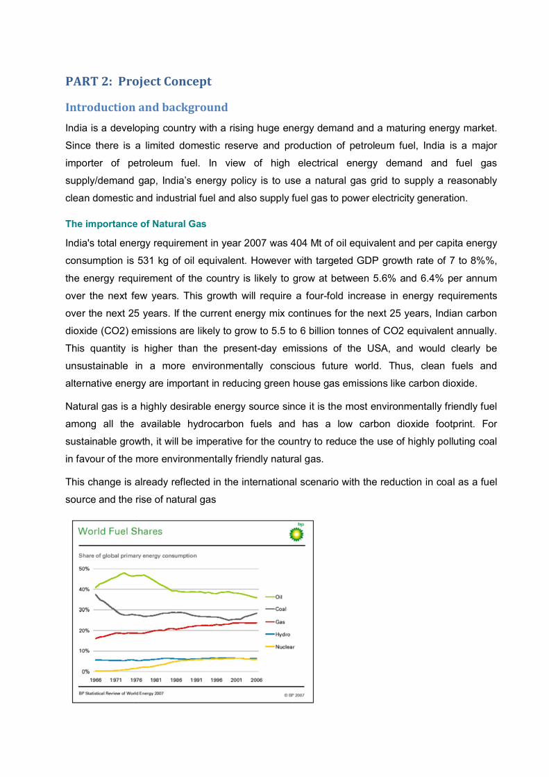
This change is already reflected in the international scenario with the reduction in coal as a fuel
source and the rise of natural gas
The demand for natural gas in India is increasing as it is a clean-burning fuel and with the
expanding network of gas pipelines, fuel is available with minimal transportation costs. Natural
gas constitutes 9% of total primary energy consumption in India. Natural gas finds application in
the power, oil refining and fertilizer sectors, city gas distribution, manufacture of petrochemicals,
sponge iron and other industrial processes. There have been a number of projections by
different bodies on future natural gas demand in India by 2030. In addition to the potential
indigenous gas supply from the Krishna-Godavari Basin (KG Basin) and the Mahanadi Basin,
the demand will need to be met by imports to meet supply shortfall for indigenously-sourced
gas. A GAIL/HSBC study estimates that by 2015, the supply shortfall is likely to be extremely
large - of the order of 75 MSCMD. These projections clearly indicate that imported gas is likely
to play a crucial role in bridging the gap between demand and supply
Especially southern India is a high energy demand area; though there are many government
driven proposals to have LNG terminals in east coast (on Bay of Bengal) at Ennore near
Chennai, Visakhapatnam in Andhra Pradesh etc. On the western coast Cochin, Mangalore,
Ratnagiri are marked for LNG terminals. These are typically of 5 MMTPA capacity (pushing
about 15~20 MMSCMD of gas) being considered at a cost of approximately 800~1000 million
USD each. These mega LNG terminals normally will take about anything from 3~4 years after
environmental clearance and financial closure are obtained.
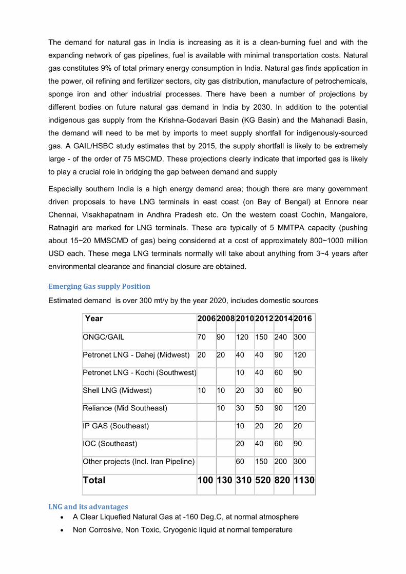
Emerging Gas supply Position
Estimated demand is over 300 mt/y by the year 2020, includes domestic sources
Year 200620082010201220142016
ONGC/GAIL 70 90 120 150 240 300
Petronet LNG - Dahej (Midwest) 20 20 40 40 90 120
Petronet LNG - Kochi (Southwest) 10 40 60 90
Shell LNG (Midwest) 10 10 20 30 60 90
Reliance (Mid Southeast) 10 30 50 90 120
IP GAS (Southeast) 10 20 20 20
IOC (Southeast) 20 40 60 90
Other projects (Incl. Iran Pipeline) 60 150 200 300
Total 100 130 310 520 820 1130
LNG and its advantages
A Clear Liquefied Natural Gas at -160 Deg.C, at normal atmosphere
Non Corrosive, Non Toxic, Cryogenic liquid at normal temperature
Odourless, Lighter than air, Assimilates in air when exposed, Safe to handle
Fewer Emission, Lower level of NOX, CO2 & particles, NO. SO2 & Mercury
Reduced Sludge, No need to use Scrubbers as being done in Power plants using Coal.
High Energy efficient - 60%. Use less fuel compared to Coal. Energy efficient about
30%.
LNG Application
Power Sector - Primary fuel, substitute to Naphtha, Diesel
Glass & Ceramic industry
Fertilizer - Feed Stock
Transport Sector - LCNG for Automobiles
Industrial Sector - Alternate fuel for direct heating and boilers
Piped gas: Household, Restaurants as cooking fuel.
LNG Cold - Fisheries, Food Industries - Cold Storage
Textiles, Engineering Units, casting & forging, Rice Mills
MINI LNG Terminals
Introduction:
A normal LNG terminal receives LNG from a bulk LNG carrier, stores, regasifies and delivers R-
LNG in the form of natural gas to the consumer(s). Since a bulk carrier will normally carry
100000~300000 M3 of LNG and since they unload their full cargo, the terminals normally have
a land based storage hold for 200000 to 500000 M3 or even in excess. This means a project of
3 MMTPA or more capacity of R-LNG, a huge storage, mega financial outlay and long time
schedule of project execution from conception to completion. This also means a natural gas
consumer or a grid to carry R-LNG.
A mini LNG terminal is much smaller in capacity. In order that the bulk LNG is received in full lot
from the carrier, a FSU is permanently berthed at the jetty; this means the land storage and
regasification facility shall be smaller and is built to meet the gas demand.
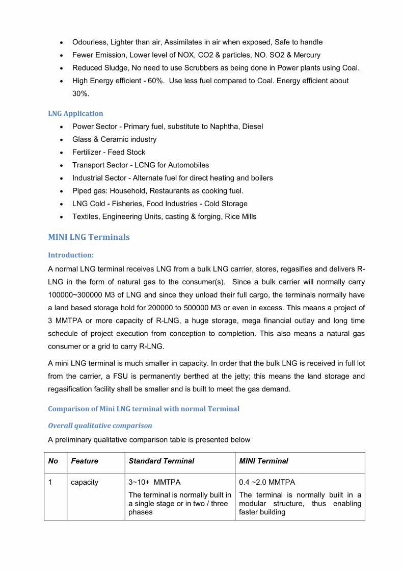
Comparison of Mini LNG terminal with normal Terminal
Overall qualitative comparison
A preliminary qualitative comparison table is presented below
No Feature Standard Terminal MINI Terminal
1 capacity 3~10+ MMTPA
The terminal is normally built in a single stage or in two / three phases
0.4 ~2.0 MMTPA
The terminal is normally built in a modular structure, thus enabling faster building
2 Storage size 30000~300000 M3
The storage is large ready to take the full tanker capacity
1000~10000
The storage is larger in FSU and very small in land
3 Storage siting Onland or offshore (FSRU); in case of FSRU, R-LNG shall be delivered onshore to a natural gas grid
Offshore for bulk storage plus onshore for smaller daily parcels of LNG. Regasification shall be onshore.
4 Storage type Large sized Flat bottomed cryogenic tanks; can be over ground, underground or in-ground tanks (see…..) Site construction
Double walled containers or bullets; can be pre-fabricated or with some site fabrication. Capacity built by banks of bullets.
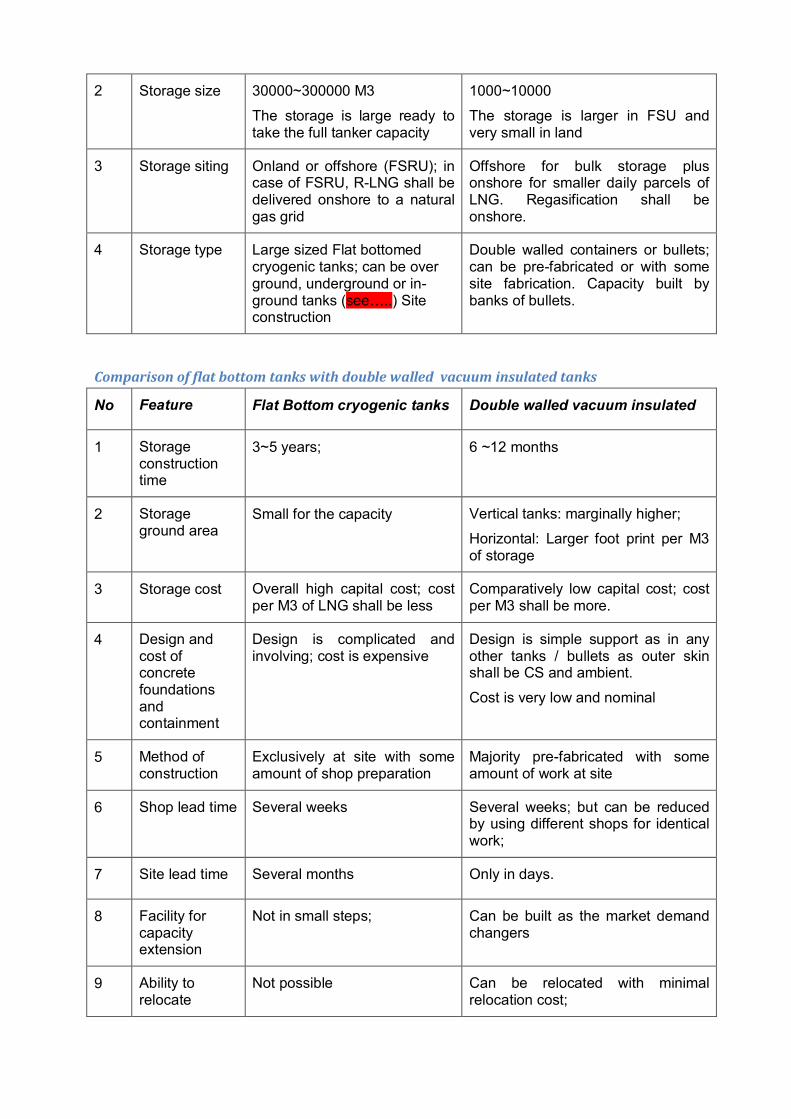
Comparison of flat bottom tanks with double walled vacuum insulated tanks
No Feature Flat Bottom cryogenic tanks Double walled vacuum insulated
1 Storage construction time
3~5 years; 6 ~12 months
2 Storage ground area
Small for the capacity Vertical tanks: marginally higher;
Horizontal: Larger foot print per M3 of storage
3 Storage cost Overall high capital cost; cost per M3 of LNG shall be less
Comparatively low capital cost; cost per M3 shall be more.
4 Design and cost of concrete foundations and containment
Design is complicated and involving; cost is expensive
Design is simple support as in any other tanks / bullets as outer skin shall be CS and ambient.
Cost is very low and nominal
5 Method of construction
Exclusively at site with some amount of shop preparation
Majority pre-fabricated with some amount of work at site
6 Shop lead time Several weeks Several weeks; but can be reduced by using different shops for identical work;
7 Site lead time Several months Only in days.
8 Facility for capacity extension
Not in small steps; Can be built as the market demand changers
9 Ability to relocate
Not possible Can be relocated with minimal relocation cost;

No Feature Flat Bottom cryogenic tanks Double walled vacuum insulated
10 Pressure storage
Very low; 0.02 atm Possible upto 8 barg; as bullets are used;
11 Send off Pump requirement
Definitely required even for low pressure discharge
Not required upto 8 barg discharge; shall be required at a higher R-LNG requirement.
12 Evaporation rate
0.1% to 0.2 % (high considering the storage volume is very high)
0.06~0.08% (low as pressure build up is allowed; and also storage amount is low)
13 Operator’s Access and maintenance
Difficult; only from the top; costly maintenance and inspection as keeping it empty/offline is very costly
Easy as it is at ground level and normally exposed; maintenance and inspection cost is low as unit can be taken offline without affecting overall performance.
14 Need of strict pressure control
Yes; the pressure is monitored in relation to the ambient pressure and temperature and is adjusted to reduce boil-off
Standard simple pressure control as the storage is already pressurised.
15 Risk of Roll-over
Roll-over is possible as stratification is possible and as new batch can be unloaded in the existing partially filled tank
Roll over is not possible
16 Boil-off generation
High; sometimes 0.25% at roll-over
Very low; and can be routed to unloading tank
17 Boil-off compression
Needed; and to be sized for a high capacity
May not be required as the vent-off may be routed to unloading tank or sent as fuel.
18 Earthquake resistance design
Difficult, complicated and costly
Simple, standard and cheaper
19 Catastrophe damage level
High level of damage as the unit is large
Can be restricted to a small number of tanks.
20 Possibility of partial operation
Not possible as the storage is large;
One or more tanks can be taken offline
Cost comparison of storage options
A typical cost comparison is given (courtesy Chart-ferox.com) below;
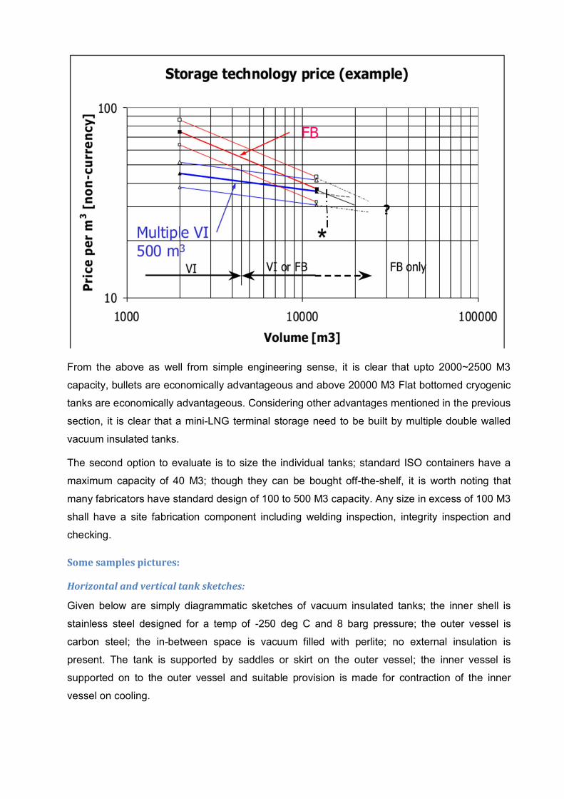
From the above as well from simple engineering sense, it is clear that upto 2000~2500 M3
capacity, bullets are economically advantageous and above 20000 M3 Flat bottomed cryogenic
tanks are economically advantageous. Considering other advantages mentioned in the previous
section, it is clear that a mini-LNG terminal storage need to be built by multiple double walled
vacuum insulated tanks.
The second option to evaluate is to size the individual tanks; standard ISO containers have a
maximum capacity of 40 M3; though they can be bought off-the-shelf, it is worth noting that
many fabricators have standard design of 100 to 500 M3 capacity. Any size in excess of 100 M3
shall have a site fabrication component including welding inspection, integrity inspection and
checking.
Some samples pictures:
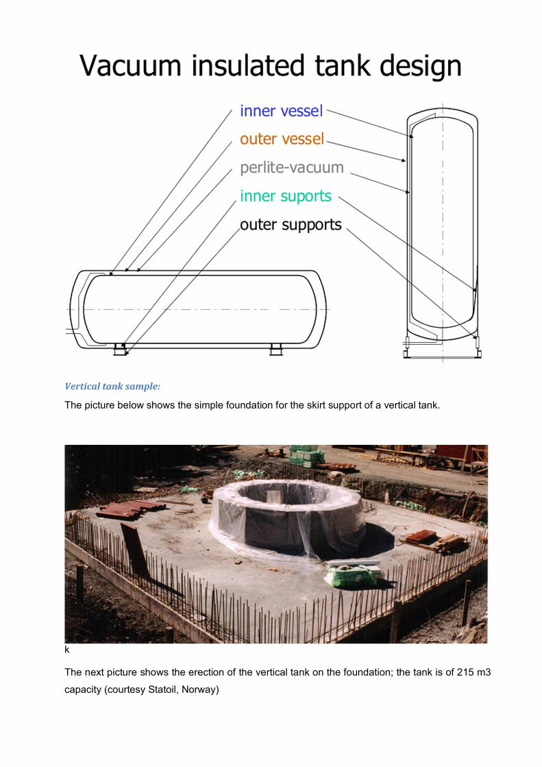
Horizontal and vertical tank sketches:
Given below are simply diagrammatic sketches of vacuum insulated tanks; the inner shell is
stainless steel designed for a temp of -250 deg C and 8 barg pressure; the outer vessel is
carbon steel; the in-between space is vacuum filled with perlite; no external insulation is
present. The tank is supported by saddles or skirt on the outer vessel; the inner vessel is
supported on to the outer vessel and suitable provision is made for contraction of the inner
vessel on cooling.
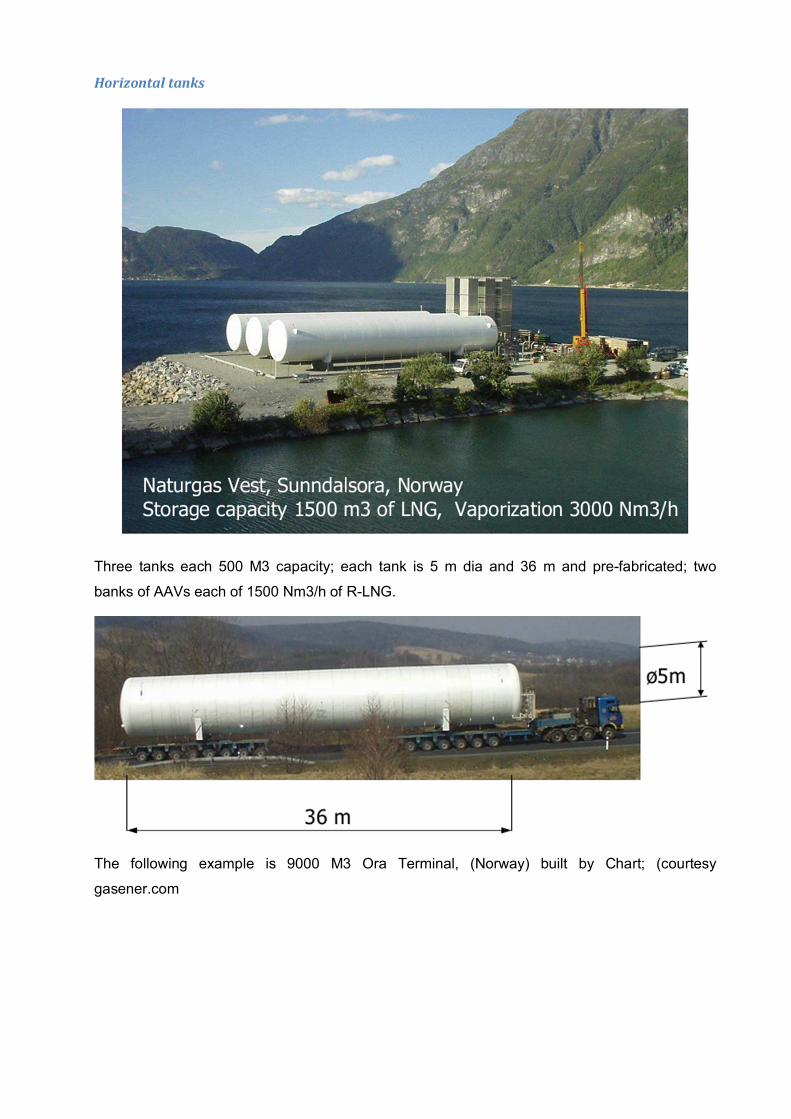
Vertical tank sample:
The picture below shows the simple foundation for the skirt support of a vertical tank.
k
The next picture shows the erection of the vertical tank on the foundation; the tank is of 215 m3
capacity (courtesy Statoil, Norway)
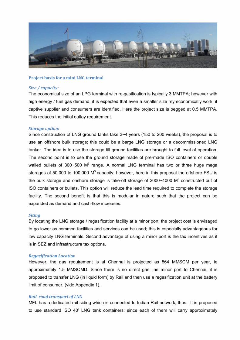
Horizontal tanks
Three tanks each 500 M3 capacity; each tank is 5 m dia and 36 m and pre-fabricated; two
banks of AAVs each of 1500 Nm3/h of R-LNG.
The following example is 9000 M3 Ora Terminal, (Norway) built by Chart; (courtesy
gasener.com
Project basis for a mini LNG terminal
Size / capacity:
The economical size of an LPG terminal with re-gasification is typically 3 MMTPA; however with
high energy / fuel gas demand, it is expected that even a smaller size my economically work, if
captive supplier and consumers are identified. Here the project size is pegged at 0.5 MMTPA.
This reduces the initial outlay requirement.
Storage option:
Since construction of LNG ground tanks take 3~4 years (150 to 200 weeks), the proposal is to
use an offshore bulk storage; this could be a barge LNG storage or a decommissioned LNG
tanker. The idea is to use the storage till ground facilities are brought to full level of operation.
The second point is to use the ground storage made of pre-made ISO containers or double
walled bullets of 300~500 M3 range. A normal LNG terminal has two or three huge mega
storages of 50,000 to 100,000 M3 capacity; however, here in this proposal the offshore FSU is
the bulk storage and onshore storage is take-off storage of 2000~4000 M3 constructed out of
ISO containers or bullets. This option will reduce the lead time required to complete the storage
facility. The second benefit is that this is modular in nature such that the project can be
expanded as demand and cash-flow increases.
Siting
By locating the LNG storage / regasification facility at a minor port, the project cost is envisaged
to go lower as common facilities and services can be used; this is especially advantageous for
low capacity LNG terminals. Second advantage of using a minor port is the tax incentives as it
is in SEZ and infrastructure tax options.
Regasification Location
However, the gas requirement is at Chennai is projected as 564 MMSCM per year, ie
approximately 1.5 MMSCMD. Since there is no direct gas line minor port to Chennai, it is
proposed to transfer LNG (in liquid form) by Rail and then use a regasification unit at the battery
limit of consumer. (vide Appendix 1).
Rail road transport of LNG
MFL has a dedicated rail siding which is connected to Indian Rail network; thus. It is proposed
to use standard ISO 40’ LNG tank containers; since each of them will carry approximately
35~45 M3 of LNG, a quick calculation indicates a need of transport of 80 containers everyday by
rail./ road
Salient features:
With the above basis in perspective, the salient features of the proposal are:
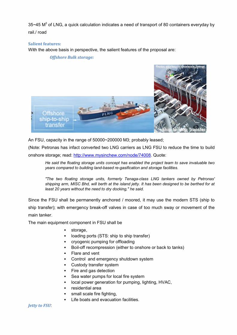
Offshore Bulk storage:
An FSU, capacity in the range of 50000~200000 M3; probably leased;
(Note: Petronas has infact converted two LNG carriers as LNG FSU to reduce the time to build
onshore storage; read: http://www.mysinchew.com/node/74008. Quote:
He said the floating storage units concept has enabled the project team to save invaluable two years compared to building land-based re-gasification and storage facilities.
"The two floating storage units, formerly Tenaga-class LNG tankers owned by Petronas'
shipping arm, MISC Bhd, will berth at the island jetty. It has been designed to be berthed for at
least 20 years without the need to dry docking," he said.
Since the FSU shall be permanently anchored / moored, it may use the modern STS (ship to
ship transfer); with emergency break-off valves in case of too much sway or movement of the
main tanker.
The main equipment component in FSU shall be
storage,
loading ports (STS: ship to ship transfer)
cryogenic pumping for offloading
Boil-off recompression (either to onshore or back to tanks)
Flare and vent
Control and emergency shutdown system
Custody transfer system
Fire and gas detection
Sea water pumps for local fire system
local power generation for pumping, lighting, HVAC,
residential area
small scale fire fighting,
Life boats and evacuation facilities.
Jetty to FSU:
Expected to be in the scope of port; jetty will carry at least the following
Offloading line from FSU
Offloading head with PERC
Boil-off return from FSU
Pressure balancing or boil-off return from and to FSU
Power cable (with redundancy)
Data cable (with redundancy)
Utility line (water, air and dry nitrogen)
Onshore storage:
At the start-up, storage of 2000~3000 M3 is envisaged; full capacity storage may be built in
phases. In view of short time of construction, the storage shall be made of bank of (pre-
fabricated) LNG 40’ ISO tank containers or partly pre-built 200~500 M3 double walled bullets.
Key features are
Modular storage concept to incrementally build capacity
Boil-off recompression
Emergency flare
multiple cryogenic pumps for offloading
Loading arms
Control room
Custody transfer system
Fire and gas detection
Deluge and firewater system
Instrument air, dry nitrogen production units
Integration with utilities and services from port
Emergency power generation unit
Fire-fighting system (extended from and integrated with port)
Rolling rail stock or road trucks
40’ ISO LNG rail tankers; depending on the frequency of loading and time for transport the
number of tankers shall be decided; at the outset one set of load is expected to be transported
every day.
Re-gasification Unit at consumerL B/L:
The final capacity requirement at consumer b/L is 1.54 MMSCMD of natural gas (see Appendix
1). This is equivalent to 2400 M3 of LNG to be regasified. The chief components in the
regasification unit are:
Local storage made of bank of ISO tank containers or double walled
bullets
Unloading arms for transfer of LNG from rail tankers to local storage
Send-off pumps to pressurize the LNG to required B/L pressure
Boil-off recompression unit
Regasification units (capacity of ~2400 M3/day of LNG or 1.54 MMSCMD
of R-LNG
Natural Gas compression (if regasification is done at low pressure, the R-
LNG may be compressed to required B/L pressure)
Custody transfer units (for measuring unloaded LNG and R-LNG)
Control Room
Fire and gas detection system
Fire-water and deluge system
Flare system
Pressure balancing lines, stand-by natural gas storage.
Utility and services system
Schematics
1) Overall schematic is given below


![FREEPORT LNG TERMINAL · 2020. 5. 20. · FREEPORT LNG TERMINAL FREEPORT MARINE OPERATIONS MANUAL [04/15/20]2 FREEPORT LNG CONTACT INFORMATION TERMINAL OFFICES Freeport LNG Terminal](https://img.pdfslide.us/doc/110x75/606c9d1603f05e3bdb64da66/freeport-lng-terminal-2020-5-20-freeport-lng-terminal-freeport-marine-operations.jpg)