Embed Size (px)
Citation preview
Neptune Deepwater LNG Port NPDES MA0040258 Fact Sheet Page 1
UNITED STATES ENVIRONMENTAL PROTECTION AGENCY NEW ENGLAND - REGION I ONE CONGRESS STREET, SUITE 1100 BOSTON, MASSACHUSETTS 02114-2023 FACT SHEET
DRAFT NATIONAL POLLUTANT DISCHARGE ELIMINATION SYSTEM (NPDES) PERMIT TO DISCHARGE TO WATERS OF THE UNITED STATES PURSUANT TO
THE CLEAN WATER ACT (CWA) NPDES PERMIT NUMBER: MA0040258 PUBLIC NOTICE START AND END DATES: February 26, 2008 – March 28, 2008 NAME AND MAILING ADDRESS OF APPLICANTS: Neptune LNG LLC 1 Liberty Square, 10th Floor Boston, MA 02109 NAME AND ADDRESS OF FACILITY WHERE DISCHARGE OCCURS: Neptune Deepwater Port Outer Continental Shelf Blocks NK 19-04 6525 and NK 19-04 6575 Massachusetts Bay, North Atlantic Planning Area RECEIVING WATER(S): Massachusetts Bay
SIC CODE:4491 Marine Cargo (Liquefied Natural Gas) Handling Offshore Terminal
Neptune Deepwater LNG Port NPDES MA0040258 Fact Sheet Page 2
Table of Contents
1.0 Proposed Action, Type of Facility, and Discharge Location ...................................................4 1.1 Port Operation......................................................................................................................4 1.2 LNG Regasification .............................................................................................................4 1.3 Pipeline Lateral and Flowline Construction ........................................................................5 1.4 Deepwater Port and Vessel Commissioning........................................................................6
2.0 Description of Intakes ..............................................................................................................6 2.1 Ballast/Engine Cooling Water and Condensate Cooling Water ..........................................6
2.1.1 Deepwater Port and Vessel Commissioning............................................................7 2.2 Fire Water ............................................................................................................................7 2.3 Emergency Ballast Water ....................................................................................................7
3.0 Description of Discharges ........................................................................................................8 3.1 Storm Water .........................................................................................................................8 3.2 Firewater ..............................................................................................................................8 3.3 Pipe Flushing and Hydrostatic Test Water - Outfall 003.....................................................8 3.4 Deepwater Port and Vessel Commissioning Cooling Water - Outfalls 04A and 04B.........9
4.0 Environmental Review under the National Environmental Policy Act ...................................9
5.0 Limitations and Conditions ....................................................................................................10
6.0 Permit Basis: Statutory and Regulatory Authority.................................................................10 6.1 Permit Requirements, Generally........................................................................................10 6.2 Technology Based Requirements ......................................................................................10 6.3 Ocean Discharge Criteria under CWA § 403 ....................................................................11 6.4 Section 316(b) of the Clean Water Act..............................................................................12
7.0 Derivation of Effluent Limits .................................................................................................13 7.1 Derivation of Effluent Limits for Pipe Flushing and Hydrostatic Test Water -Outfall 00313
7.1.1 Flow .......................................................................................................................13 7.1.2 Total Suspended Solids (TSS) ...............................................................................13 7.1.3 Fluorescein Dye .....................................................................................................13
7.2 Derivation of Effluent Limits for Deepwater Port and Vessel Commissioning Cooling Water - Outfalls 04A and 04B ...................................................................................................14
7.2.1 Flow .......................................................................................................................14 7.2.2 Temperature ...........................................................................................................14
8.0 316 (b) Cooling Water Intake Requirements .........................................................................16 8.1 Cooling Water Intake Structures........................................................................................16 8.2 Cooling Water Intake Monitoring Requirements ..............................................................19
9.0 Essential Fish Habitat.............................................................................................................19
10.0 Endangered Species Act.........................................................................................................20
11.0 National Marine Sanctuaries Act ...........................................................................................20
12.0 Comment Period, Hearing Requests, and Procedures for Final Permit .................................21
13.0 EPA and MassDEP Contacts..................................................................................................21
Neptune Deepwater LNG Port NPDES MA0040258 Fact Sheet Page 3
Figure 1 – Location Map of Proposed Neptune LNG Pipeline and Terminal Figure 2 – Neptune Deepwater Port Schematic Figure 3 – Process Flow Diagram – Closed Loop LNG Vaporizer Attachment A - Summary of Essential Fish Habitat Designation
Neptune Deepwater LNG Port NPDES MA0040258 Fact Sheet Page 4
1.0 Proposed Action, Type of Facility, and Discharge Location
The above named applicant has applied to the U.S. Environmental Protection Agency (EPA) for the issuance of a NPDES permit to withdraw sea water from Massachusetts Bay and discharge storm water, firewater, cooling water and hydrostatic test water into the Massachusetts Bay.
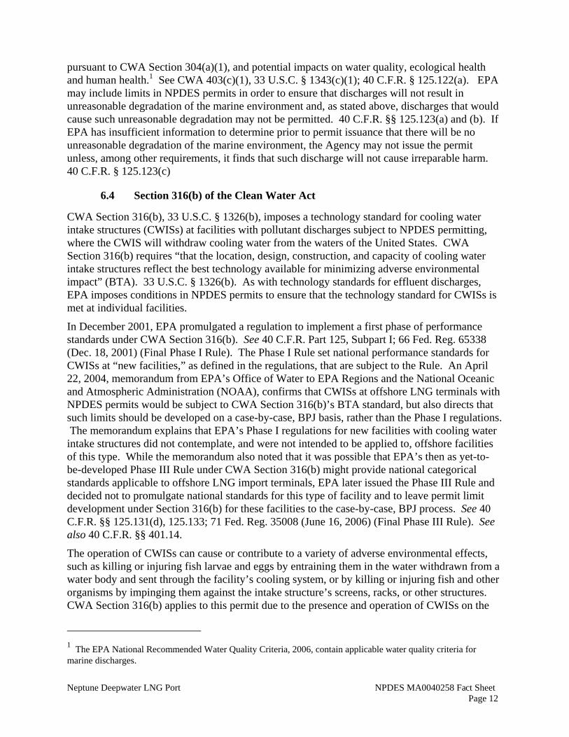
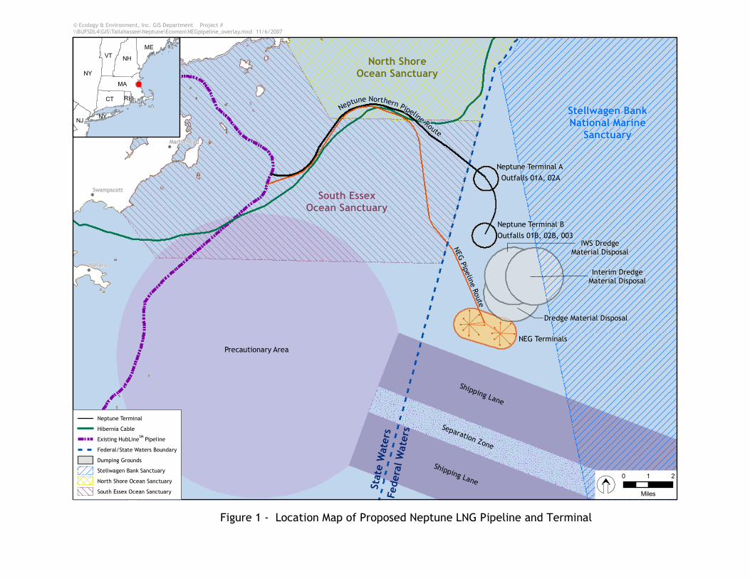
The seawater withdrawal and discharge are the result of the construction and operation of a new offshore liquefied natural gas (LNG) terminal in federal waters of Massachusetts Bay. New pipelines will facilitate the delivery of regasified liquefied natural gas (LNG) from the Northeast Port to onshore markets in New England. Specifically designed ships containing LNG will deliver regasified natural gas into the new gas pipeline via the new offshore terminal. The new pipeline will be connected to the existing offshore and land based natural gas distribution system. The new LNG terminal will be a deepwater port, named Neptune, located in federal waters in the eastern side of Massachusetts Bay in Office of Coast Survey (OCS) blocks NK 19-04 6525 and NL 19-04 6575, approximately 22 miles northeast of Boston in a water depth of approximately 260 feet. Figure 1 shows the location of the deepwater port and transmission lines.
1.1 Port Operation
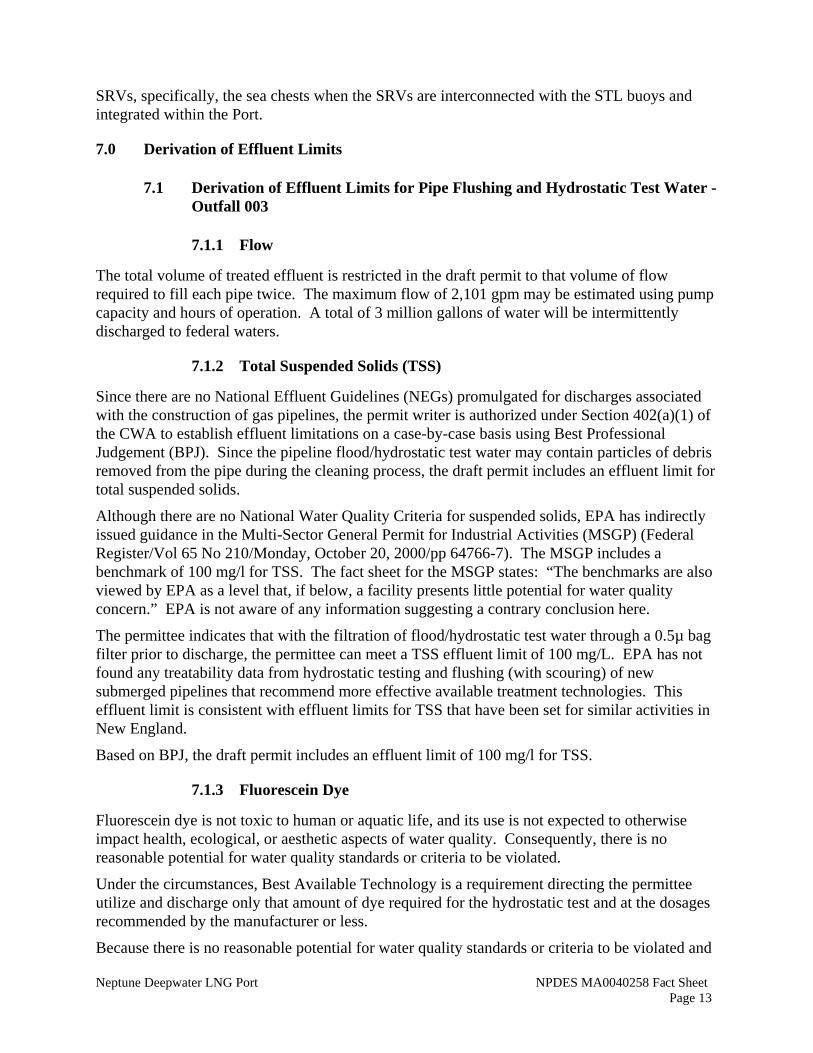
The LNG deepwater port will consist of two unloading buoy systems (referred to as “A” and “B” on figures and in draft permit) in a water depth of approximately 260 feet, eight wire rope and chain mooring lines connecting each unloading buoy to anchor points on the seabed, eight suction pile anchor points, one flexible riser from the pipeline to each buoy, riser manifolds, approximately 2.3 miles of natural gas flowline connecting the two buoy systems, a 10.9 mile long, 24-inch natural gas transmission line connecting the port to the existing “Hubline” offshore natural gas line, a transition manifold, hot tap and connecting pipe tying into the Hubline. A schematic of the Neptune LNG deepwater port is shown in Figure 2.
During the vaporization of LNG and distribution of natural gas to the pipeline, up to two LNG shuttle and regasification vessels (SRVs), each with a capacity of approximately 150,000 cubic meters (m3), will temporarily moor at the deepwater port by means of a submerged unloading buoy system. Two unloading buoys will each moor one SRV on location throughout the unloading cycle by means of mooring lines and anchor points located on the seabed. Two unloading buoys at the port will allow natural gas to be delivered in a continuous flow, without interruption, by having brief overlap between arriving and departing SRVs. As the first SRV moored at the deepwater port finishes unloading, a second SRV (following its transit from an overseas loading point) will moor at the deepwater port. After all of its LNG has been vaporized and unloaded, the first SRV will disconnect from the unloading buoy and proceed to an overseas loading point to reload. In the meantime, a third LNG carrier, already in transit to the deepwater port will repeat the cycle. This sequence will provide the operational flexibility to allow uninterrupted delivery of natural gas using three or more SRVs.
1.2 LNG Regasification
LNG is natural gas that has been cooled to about minus 260ºF for efficient shipment and storage as a liquid. LNG is more compact that the gaseous equivalent, with a volumetric differential of about 610 to 1. LNG can be transported long distances across oceans using specially designed ships, thus allowing access to stranded reserves that cannot be transported by conventional
Neptune Deepwater LNG Port NPDES MA0040258 Fact Sheet Page 5
pipelines.
The SRVs will be equipped to store, transport and vaporize LNG, and to odorize and meter natural gas that will then be sent out through new and existing conventional subsea pipelines. Each double hulled SRV will have insulated LNG storage tanks within its inner hull. Each tank will be equipped with an in-tank pump to circulate and transfer LNG, at a temperature of -256 ºF, to the vaporization facilities on the deck of the SRV.
The onboard vaporization systems will have a capacity of approximately 750 million standard cubic feet per day (MMscfd) and consist of three individual vaporization units with capacity to vaporize 250 MMscfd each by raising the temperature of the LNG to at least 32ºF. Under normal operation, two units will be in service with a combined maximum sendout capacity of 500 MMscfd. The third vaporization unit will be on standby mode. The vaporization system will have the capacity to empty the 150,000 m3 vessel in four to eight days.
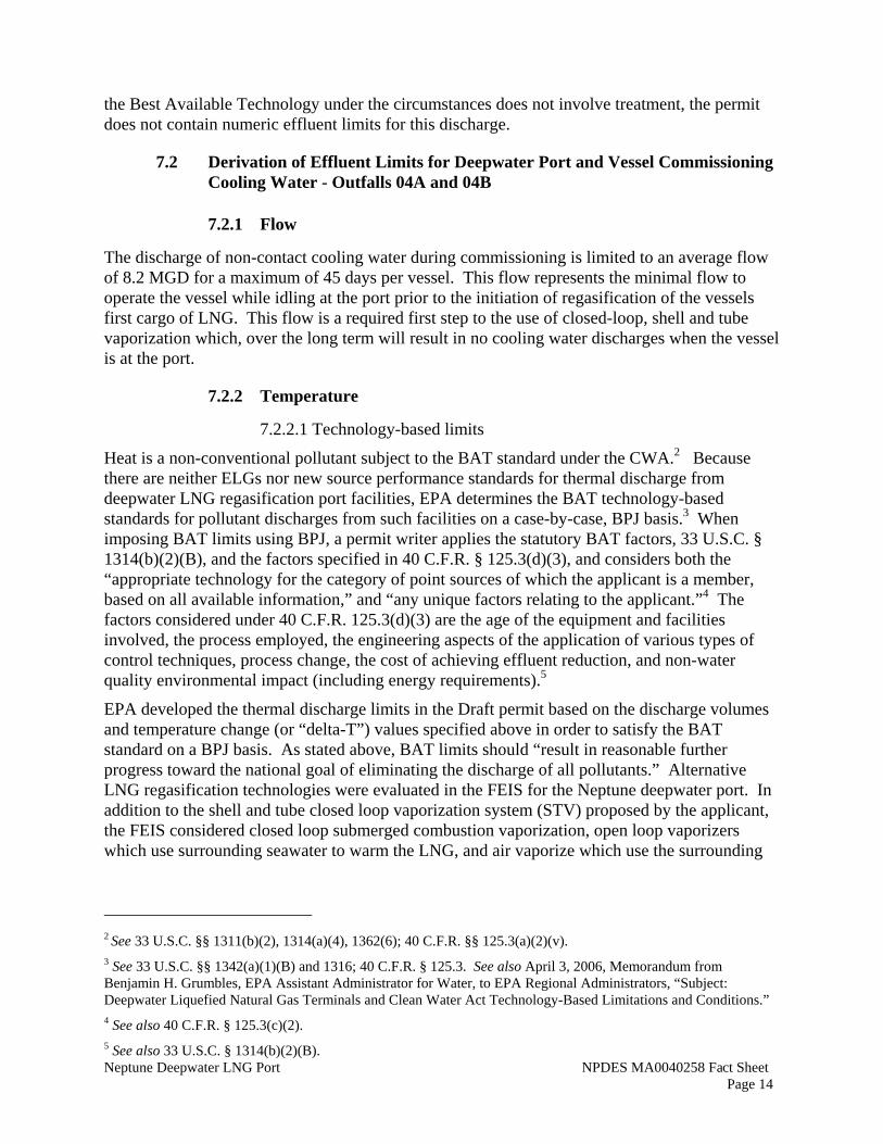
The LNG will be heated in a two-step closed loop system. In the first step, a water-glycol solution will be heated in a compact printed circuit heat exchanger (PCHE) by steam produced in two marine auxiliary boilers. In the second step, the warmer water-glycol solution will heat the LNG in a shell and tube heat exchanger. Figure 3 shows the process flow diagram for the closed-loop vaporization system.
As the LNG is vaporized and offloaded through the pipelines, the double bottoms and double sides of the SRV will be ballasted (filled with sea water) to maintain the proper buoyancy and stability of the vessel. The ballast water will also be recirculated for cooling the boilers used for regasification, as described above. No ballast/cooling water will be discharged.
Two unloading buoys will be utilized so that natural gas can be delivered in a continuous flow, without interruption, by having an approximately 9-hour overlap between arriving and departing SRVs.
1.3 Pipeline Lateral and Flowline Construction
The construction project includes the installation of 10.9 miles of 24-inch natural gas transmission line, known as the Pipeline Lateral, to connect the Neptune deepwater port to the existing 30-inch natural gas Hubline in Massachusetts Bay. Within the deepwater port, 2.5 miles of 24-inch natural gas transmission line will be used to connect the two unloading buoy systems. The transmission line within the port is known as the Flowline. Figure 1 depicts the layout of existing and new gas transmission lines.
Filtered seawater will be used following construction of the pipeline to ensure pipeline integrity. These activities involve internal cleaning and hydrostatic testing as follows:
• Internal Cleaning – Although care will be taken during fabrication and installation, minimal amounts of debris may be left in the pipeline. The pipe will first be flooded prior to gauging to remove any foreign material left in the pipeline. Each section of the pipeline will then be internally cleaned using a brush pig. Following cleaning, a pressure propelled measuring device, known as a gauging pipe, will be passed through the pipes to ensure that they meet minimum dimensions and to identify excessively out-of-round pipe, dents, projections or other obstructions.
• Hydrostatic Testing – Upon acceptance of the gauge pig run, the pipes will be flooded again with filtered seawater and fluorescent dye. The hydrostatic test will be
Neptune Deepwater LNG Port NPDES MA0040258 Fact Sheet Page 6
conducted at a minimum pressure of 1.25 times the maximum allowable operating pressure and for a minimum duration of 8 hours.
1.4 Deepwater Port and Vessel Commissioning
The initial commissioning of the port infrastructure and each SRV will require non-routine seawater cooling water intake and discharges to keep the vessel power generation systems operating while the vessel is idling at the port. The commissioning activities generally will include the docking connection to the buoy, testing of equipment and controls (i.e. valves and pipeline integrity) and safety systems, re-gasification skid performance testing, and stack emission compliance testing. Neptune anticipates that these commissioning functions should be completed in a 20 day period for each SRV calling on the port. Neptune has written into its charter agreement that the vessel operator has three attempts to meet the SRV re-gas performance specifications and pass the acceptance test. (Vessel sea trials will have been completed before and vessel arrives at the port to begin the deepwater port commissioning phase).
In a worst case scenario, each vessel would require 40 days (20 day initial regas test, 10 day second, and 10 day final) to complete its commissioning functions. In addition, the emission compliance test would be conducted following the regasification system commissioning which could take an additional 5 days per vessel, depending on weather and logistics. Neptune seeks a total of 45 days to discharge on the buoy during commissioning/testing for each vessel. It is likely that this would not be 45 days continuous time on the buoy as the vessel would likely leave for modifications/repair before attempting the acceptance tests for a second or third time. Should the commissioning go as planned, both buoys and subsea infrastructure would be commissioned with the first SRV cargo.
2.0 Description of Intakes
2.1 Ballast/Engine Cooling Water and Condensate Cooling Water
Each SRV’s power plant will use four dual fuel diesel engines, one producing 5.7 MW and three producing 11.4 MW. Two 11.4-MW engines would be used for electric power generation when the SRV is moored. One 11.4-MW and one 5.7-MW engine will be needed for propulsion and electrical power generation when the SRV is underway. Propulsion will be provided by a single-screw driven by twin electric motors.
The dual-fuel diesel engines will burn 99 percent natural gas and 1 percent marine diesel as pilot fuel. The SRVs will use two low-pressure marine auxiliary boilers each rated at about 282 MMBtu per hour. These will be designed to operate on cargo boil-off gas and vaporized LNG. The steam will be supplied to the cargo vaporization units.
SRV will have a high and a low seawater intake chests (sea chests). Each sea chest will be have 33.7square feet of open area. The low sea chest will be located near the bottom of the vessel’s hull in a near horizontal plane (due to the curvature in the hull) with the centerline of the sea chest approximately 33 feet below the water surface. The high chest will lie in a near vertical plane with it’s centerline approximately 8 feet above the low sea chest. To minimize entrainment of marine organisms, each sea chest will contain screen openings that are approximately 1 inch by 12 inches. At the design LNG regasifying rate, intake velocity will be 0.11 ft/s. Allowing for practical cargo ballast operations in all conditions, intake velocity will be
Neptune Deepwater LNG Port NPDES MA0040258 Fact Sheet Page 7
approximately 0.38 ft/s. In all cases, with the exception of when the fire pumps are on, the intake velocity will be below 0.5 ft/s.
The flow rate at the open sea chest will be 2.25 million gallons per day (MGD) for each SRV. Only one of the two sea chests will be opened when the SRV is at the buoy. The second sea chest will be used at the buoy only during emergencies to supplement ballast water or the firewater system. During normal operation, the total volume will be diverted to the ballast tanks. Engine cooling water will be supplied directly by re-circulated ballast water.
It is expected that when the port is operating at maximum capacity, the port will be operating continuously with one SRV arriving and beginning regasification as another is finishing up and preparing to depart the port. This overlap is expected to occur for approximately 9 hours every six days. Therefore, while the maximum daily intake from each buoy will be 2.25 MGD, the total annual intake at each buoy is 437 million gallons, or an average monthly intake of 1.2 MGD.
2.1.1 Deepwater Port and Vessel Commissioning
Seawater intake during commissioning has been estimated to average about 8.2 MGD with flow rates as high as 13,900 gpm for up to 1 hour if the auxiliary steam dump condenser is needed. Although the steam dump condenser is not expected to operate often, it is required to reject heat when the marine boilers must remain operating and the regas skid is temporarily shutdown (this may occur during short shutdowns of the regas skids during commissioning or during stack emission testing at low gas sendout flows). Seawater will be used to supply the central freshwater coolers and dump condenser and freshwater generators. Seawater will be withdrawn from both the upper and lower sea chests; and the intake velocities at both sea chests will be below 0.5 feet per second.
2.2 Fire Water
The testing of the fire response system, which utilizes seawater, occurs every two weeks when the vessel is on a voyage. When the SRV is at the buoy, the fire system will be tested approximately four times per year, or as requested by the Coast Guard.
There will be two fire pumps with a combined capacity of 317,004 gallons per hour (gph) to draw down seawater from the sea chests in the event of a fire.
During the testing of the fire system if water is drawn from the same sea chest as the ballast water; the intake velocity will increase from the normal 0.11 ft/s to approximately 0.45 ft/s. If it is drawn by opening the other sea chest as well, the intake velocity in both chests will be approximately 0.23 ft/s.
2.3 Emergency Ballast Water
During an emergency requiring rapid off-loading of cargo, additional ballast water will be required for distribution of cargo and ballast water. Additional ballast water will be taken by either opening the closed sea chest in addition to the one already open, or by drawing extra water from the already open one. There will be three identical pumps rated to 660,400 gph dedicated to emergency ballast water. Only two of the pumps will be used simultaneously. The applicant estimates that usage during an emergency event would be to use two of the pumps continuously for up to three hours. The probable total peak water intake would be approximately 3.96 million
Neptune Deepwater LNG Port NPDES MA0040258 Fact Sheet Page 8
gallons per event.
If the closed sea chest is opened when taking in additional ballast water, the intake velocity in both chests will be approximately 0.9 ft/s. In case the additional ballast water is drawn without opening the other chest, then the intake velocity will increase to approximately 1.8 ft/s for up to three hours per event.
3.0 Description of Discharges
3.1 Storm Water
Precipitation runoff from each SRV deck, outside the utility areas, is routed to outlets on the sides of the SRVs. Storm water discharge for each SRV is estimated to average 8,700 gallons per day (gpd) from the deck area, based on 30-year average rainfall. On days when incoming and outgoing vessels overlap at the port, total discharge would average 11,900 gallons per day (assuming a 9 hour overlap). The peak daily rainfall is estimated at 0.6 MGD for a single vessel and 0.8 MGD when vessels overlap.
Rainwater and oil from the utility areas that include power generation, boil-off gas compressor, emergency diesel generator, diesel tank, and diesel loading areas where there is a potential for the presence of petroleum hydrocarbons will be contained in drain or drip pans. A set of four drain pans will be located in the steering flat and another set of four drain pans will be located in the forecastle. The drain pans will collect rainwater, machine washdown water and any drips or spills from the equipment in the vicinity. The water in the drain pans will be collected and diverted to storage tanks. The water will be treated and discharged when the SRV is in transit outside U.S. waters. The draft permit includes a narrative best management practice prohibiting the discharge of rainwater from the utility area drain pans.
3.2 Firewater
During the testing or use of the fire extinguishing system, the seawater used in the system will be discharged at an average rate of 300,000 gallons per hour. The firewater will be discharged at multiple outfalls throughout the facility through the fire protection system and the system bypass.
The testing of the fire system will require a water discharge of 80,000 gallons over a 15 minute period. While at sea, the fire system must be tested approximately every 2 weeks. When the vessel is at the buoy, the fire system will be tested approximately four times per year.
No specific effluent limits are provided for discharge generated from testing the fire system at the buoy.
3.3 Pipe Flushing and Hydrostatic Test Water - Outfall 003
Outfall 003 consists of discharges resulting from cleaning and testing the transmission line (10.9 miles) and flowline (2.5 miles). During construction, the pipes will be filled twice with seawater. The first filling is to flush and scrub the pipes which will be filtered through bag filters topside prior to discharge. No chemicals will be added to the first filling. The line will then be filled a second time with dye in filtered seawater and then hydrostatically tested. After the hydrostatic test is complete, the water will be filtered again and discharged to the bay.
No chemicals will be added to the pipeline except for fluorescent dye (Champion Servo
Neptune Deepwater LNG Port NPDES MA0040258 Fact Sheet Page 9
Fluorescein Liquid Dye) which will be used to assist divers in leak detection during hydrostatic testing. The dye will be added to the water at an average concentration of 450 parts per million (ppm). Fluorescein liquid dye is non-toxic to aquatic life and humans and is used in medical procedures (including opthhalmology to reveal corneal lesions) and as a tracer in marine environments.
At no time will the filled pipe be left open. Tie-in to the hubline will be accomplished using specialized valves at the ends of pipe to prevent water/sediments from entering the pipe.
3.4 Deepwater Port and Vessel Commissioning Cooling Water - Outfalls 04A and 04B
As described in Section 2.1.1 above, seawater intake during commissioning has been estimated to average about 8.2 MGD with flow rates as high as 13,900 gpm during short discrete periods if the steam dump condenser is in operation.
The cooling water discharge is at the bottom of the vessel (about 37 feet below the waterline). The cooling water discharge flow from the central freshwater coolers will average 8.2 MGD and the temperature differential will be 5 to 8ºC. If the steam dump is required, the temperature differential could rise to as high as 10ºC, up to one hour
4.0 Environmental Review under the National Environmental Policy Act
Section 511(c)(1) of the Clean Water Act (CWA), 33 U.S.C. § 1371(c)(1), expressly provides that EPA issuance of an NPDES permit under CWA § 402, 33 U.S.C. § 1341, to a facility that is a “new source” under CWA § 306, 33 U.S.C. § 1316, is one of only two types of EPA actions under the CWA that are subject to review under the National Environmental Policy Act of 1969 (NEPA), 42 U.S.C. §§ 4321, et seq. Where such an action is determined to be a major federal action significantly affecting the quality of the human environment, NEPA requires that the federal agency or agencies proposing, major federal actions significantly affecting the quality of the human environment to first complete an “environmental impact statement” (EIS) evaluating the proposed action, reasonable alternatives to it and the environmental effects of the proposed and alternative actions. See 40 C.F.R. Part 1502. EPA regulations at 40 C.F.R. Part 6, Subparts A, B, D, and F also address the preparation of EISs in conjunction with EPA proposals to issue NPDES permits to new sources.
The Deepwater Port Act (DPA), 33 U.S.C. §§ 1501 et seq., specifies that deepwater ports shall be considered “new sources” under the CWA. See 33 U.S.C. § 1502(9)(D). As a result, by operation of the DPA, NEPA applies to EPA’s proposal to issue an NDPES permit to the NEPTUNE deepwater port. At the same time, the DPA also specifies that:
[f]or all [Deepwater Port Act license] applications, the Secretary [of Transportation], in cooperation with other involved Federal Agencies and departments, shall comply with the National Environmental Policy Act of 1969 (42 U.S.C. 4332). Such compliance shall fulfill the requirement of all Federal agencies in carrying out their responsibilities under the National Environmental Policy Act pursuant to this Act.
33 U.S.C. § 1504(f). Consistent with this provision of the DPA, the United States Coast Guard (USCG) and the United States Maritime Administration (MARAD) served as lead agencies preparing an EIS to satisfy NEPA, and EPA (and other agencies) cooperated with the USCG and
Neptune Deepwater LNG Port NPDES MA0040258 Fact Sheet Page 10
MARAD in the preparation of the EIS. See USCG’s Draft and Final EISs for the Neptune LLC Liquefied Natural Gas Deepwater Port License Application. Also consistent with the DPA, this EIS satisfies EPA’s NEPA obligations with respect to issuance of this NPDES permit.
The EIS includes detailed discussion of the proposed project and alternatives considered to it. Many aspects of the project are discussed in the EIS, including pollutant discharges and cooling water withdrawals. This fact sheet provides additional discussion focused specifically on aspects of the proposed facility that are subject to regulation under the NPDES permit.
5.0 Limitations and Conditions
The limits on pollutant discharges and cooling water withdrawals, as well as the monitoring requirements, proposed by EPA for the Port may be found in the draft NPDES permit. The basis for these requirements is discussed below.
6.0 Permit Basis: Statutory and Regulatory Authority
6.1 Permit Requirements, Generally
The Clean Water Act (CWA) prohibits the discharge of pollutants to waters of the United States without authorization by a National Pollutant Discharge Elimination System (NPDES) permit, unless the discharge is otherwise authorized by the CWA. Technology-based and water quality-based effluent limitations and other requirements, including monitoring and reporting, are typically implemented by including them in NPDES permits issued to specific facilities. See 33 U.S.C. §§ 1311(a) and (b), 1313, 1318(a), 1326(b), 1341, 1342, 1343. The draft NPDES permit here was developed in accordance with various statutory and regulatory requirements established pursuant to the CWA. The regulations governing the EPA NPDES permit program are generally found at 40 CFR Parts 122, 124, 125, and 136. For this permit, EPA considered technology-based and water quality-based requirements under the CWA, including the CWA’s Ocean Discharge Criteria. In addition, EPA considered any requirements that might arise out of any applicable statutes in addition to the CWA.
6.2 Technology Based Requirements
Technology-based effluent limits represent the minimum level of pollutant discharge control that dischargers must achieve under the CWA. The CWA requires that different types of pollutant discharges be controlled to levels that reflect the capability of certain technological measures. These technology standards vary depending on the type of pollutant and facility in question. See 33 U.S.C. §§ 1311(b), 1314, 1316; 40 C.F.R. § 125.3. Sections 301(b) and 306 of the CWA and 40 CFR Part 125 Subpart A require that pollutant discharges be reduced to a level equivalent to using the best practicable control technology currently available (BPT), best conventional control technology (BCT) for conventional pollutants, the best available technology economically available (BAT) for toxics and non-conventional pollutants, and the best available demonstrated control technology (BADCT) for discharges from “new sources,” as defined under the CWA. See 33 U.S.C. §§ 1316(a); 40 C.F.R. §§ 122.2, 122.29. BAT limits are also supposed to “result in reasonable further progress toward the national goal of eliminating the discharge of all pollutants.” 33 U.S.C. § 1311(b)(2)(A). These technology-based requirements are then to be reflected in NPDES permits issued to specific facilities. See 33 U.S.C. §§ 1311, 1316, 1342(a); 40 C.F.R. §§ 122.29, 125.3. Any applicable new source performance standards must be met
Neptune Deepwater LNG Port NPDES MA0040258 Fact Sheet Page 11
when the new source commences operations. See 40 C.F.R. § 122.29(d)(4) and (5). Compliance schedules and deadlines not in accordance with the statutory deadlines of the CWA cannot be authorized by a NPDES permit.
EPA regulations found at 40 C.F.R. Part 125, Subpart A, set forth procedures, standards and criteria for the development and imposition of technology-based requirements in NPDES permits under Section 301(b) of the CWA, including the application of EPA-promulgated National Effluent Guidelines (NEGs) (i.e., technology-based effluent limitations developed for entire industrial categories which are then applied to specific facilities through NPDES permits) and, when no relevant NEGs are in effect, the development of case-by-case, Best Professional Judgment (BPJ) determinations of technology-based discharge limits under Section 402(a)(1) of the CWA. See 40 C.F.R. § 125.3.
EPA has not promulgated technology-based NEGs for pollutant discharges from LNG deepwater ports or any other type of deepwater port. In addition, EPA has not promulgated any new source performance standards for deepwater ports. Therefore, all technology-based effluent limits for the Port’s NPDES permit have been developed on a case-by-case, BPJ basis, as discussed further below.
6.3 Ocean Discharge Criteria under CWA § 403
Point source pollutant discharges to marine waters are subject to the Ocean Discharge Criteria (ODC) under Section 403 of the Clean Water Act (CWA). 33 U.S.C. § 1343. The ODC apply to NPDES permits for pollutant discharges into the territorial seas, the contiguous zone and the ocean. EPA has promulgated guidelines for regulating discharges to satisfy CWA section 403 and give effect to the ODC. See 40 C.F.R. Part 125, Subpart M.
EPA conducts an Ocean Discharge Criteria Evaluation (ODCE) using the guidelines in 40 C.F.R. Part 125, Subpart M to determine whether and the extent that the discharge will cause degradation of the marine environment. 40 C.F.R. 125.122(a). EPA may not issue an NPDES permit to authorize any pollutant discharge that the Agency determines will cause “unreasonable degradation of the marine environment.” 40 C.F.R. 125.123(b). The ODC defines "unreasonable degradation of the marine environment" to mean:
• Significant adverse changes in ecosystem diversity, productivity, and stability of the biological community within the area of discharge and surrounding biological communities;
• Threat to human health through direct exposure to pollutants or through consumption of exposed aquatic organisms; or
• Loss of aesthetic, recreational, scientific or economic values which is unreasonable in relation to the benefit derived from the discharge.
See 40 C.F.R. 125.121(e). CWA Section 403(c) guidelines require that a number of factors be considered in the determination of degradation. These factors include the amount and nature of the pollutants, the potential transport of the pollutants, the character and uses of the receiving water and its biological communities, the impacts on recreational and commercial fishing, the existence of special aquatic sites (including parks, refuges, etc.), any applicable requirements of an approved Coastal Zone Management plan, marine water quality criteria developed by EPA
Neptune Deepwater LNG Port NPDES MA0040258 Fact Sheet Page 12
pursuant to CWA Section 304(a)(1), and potential impacts on water quality, ecological health and human health.1 See CWA 403(c)(1), 33 U.S.C. § 1343(c)(1); 40 C.F.R. § 125.122(a). EPA may include limits in NPDES permits in order to ensure that discharges will not result in unreasonable degradation of the marine environment and, as stated above, discharges that would cause such unreasonable degradation may not be permitted. 40 C.F.R. §§ 125.123(a) and (b). If EPA has insufficient information to determine prior to permit issuance that there will be no unreasonable degradation of the marine environment, the Agency may not issue the permit unless, among other requirements, it finds that such discharge will not cause irreparable harm. 40 C.F.R. § 125.123(c)
6.4 Section 316(b) of the Clean Water Act
CWA Section 316(b), 33 U.S.C. § 1326(b), imposes a technology standard for cooling water intake structures (CWISs) at facilities with pollutant discharges subject to NPDES permitting, where the CWIS will withdraw cooling water from the waters of the United States. CWA Section 316(b) requires “that the location, design, construction, and capacity of cooling water intake structures reflect the best technology available for minimizing adverse environmental impact” (BTA). 33 U.S.C. § 1326(b). As with technology standards for effluent discharges, EPA imposes conditions in NPDES permits to ensure that the technology standard for CWISs is met at individual facilities.
In December 2001, EPA promulgated a regulation to implement a first phase of performance standards under CWA Section 316(b). See 40 C.F.R. Part 125, Subpart I; 66 Fed. Reg. 65338 (Dec. 18, 2001) (Final Phase I Rule). The Phase I Rule set national performance standards for CWISs at “new facilities,” as defined in the regulations, that are subject to the Rule. An April 22, 2004, memorandum from EPA’s Office of Water to EPA Regions and the National Oceanic and Atmospheric Administration (NOAA), confirms that CWISs at offshore LNG terminals with NPDES permits would be subject to CWA Section 316(b)’s BTA standard, but also directs that such limits should be developed on a case-by-case, BPJ basis, rather than the Phase I regulations. The memorandum explains that EPA’s Phase I regulations for new facilities with cooling water intake structures did not contemplate, and were not intended to be applied to, offshore facilities of this type. While the memorandum also noted that it was possible that EPA’s then as yet-to-be-developed Phase III Rule under CWA Section 316(b) might provide national categorical standards applicable to offshore LNG import terminals, EPA later issued the Phase III Rule and decided not to promulgate national standards for this type of facility and to leave permit limit development under Section 316(b) for these facilities to the case-by-case, BPJ process. See 40 C.F.R. §§ 125.131(d), 125.133; 71 Fed. Reg. 35008 (June 16, 2006) (Final Phase III Rule). See also 40 C.F.R. §§ 401.14.
The operation of CWISs can cause or contribute to a variety of adverse environmental effects, such as killing or injuring fish larvae and eggs by entraining them in the water withdrawn from a water body and sent through the facility’s cooling system, or by killing or injuring fish and other organisms by impinging them against the intake structure’s screens, racks, or other structures. CWA Section 316(b) applies to this permit due to the presence and operation of CWISs on the
1 The EPA National Recommended Water Quality Criteria, 2006, contain applicable water quality criteria for marine discharges.
Neptune Deepwater LNG Port NPDES MA0040258 Fact Sheet Page 13
SRVs, specifically, the sea chests when the SRVs are interconnected with the STL buoys and integrated within the Port.
7.0 Derivation of Effluent Limits
7.1 Derivation of Effluent Limits for Pipe Flushing and Hydrostatic Test Water -Outfall 003
7.1.1 Flow
The total volume of treated effluent is restricted in the draft permit to that volume of flow required to fill each pipe twice. The maximum flow of 2,101 gpm may be estimated using pump capacity and hours of operation. A total of 3 million gallons of water will be intermittently discharged to federal waters.
7.1.2 Total Suspended Solids (TSS)
Since there are no National Effluent Guidelines (NEGs) promulgated for discharges associated with the construction of gas pipelines, the permit writer is authorized under Section 402(a)(1) of the CWA to establish effluent limitations on a case-by-case basis using Best Professional Judgement (BPJ). Since the pipeline flood/hydrostatic test water may contain particles of debris removed from the pipe during the cleaning process, the draft permit includes an effluent limit for total suspended solids.
Although there are no National Water Quality Criteria for suspended solids, EPA has indirectly issued guidance in the Multi-Sector General Permit for Industrial Activities (MSGP) (Federal Register/Vol 65 No 210/Monday, October 20, 2000/pp 64766-7). The MSGP includes a benchmark of 100 mg/l for TSS. The fact sheet for the MSGP states: “The benchmarks are also viewed by EPA as a level that, if below, a facility presents little potential for water quality concern.” EPA is not aware of any information suggesting a contrary conclusion here.
The permittee indicates that with the filtration of flood/hydrostatic test water through a 0.5µ bag filter prior to discharge, the permittee can meet a TSS effluent limit of 100 mg/L. EPA has not found any treatability data from hydrostatic testing and flushing (with scouring) of new submerged pipelines that recommend more effective available treatment technologies. This effluent limit is consistent with effluent limits for TSS that have been set for similar activities in New England.
Based on BPJ, the draft permit includes an effluent limit of 100 mg/l for TSS.
7.1.3 Fluorescein Dye
Fluorescein dye is not toxic to human or aquatic life, and its use is not expected to otherwise impact health, ecological, or aesthetic aspects of water quality. Consequently, there is no reasonable potential for water quality standards or criteria to be violated.
Under the circumstances, Best Available Technology is a requirement directing the permittee utilize and discharge only that amount of dye required for the hydrostatic test and at the dosages recommended by the manufacturer or less.
Because there is no reasonable potential for water quality standards or criteria to be violated and
Neptune Deepwater LNG Port NPDES MA0040258 Fact Sheet Page 14
the Best Available Technology under the circumstances does not involve treatment, the permit does not contain numeric effluent limits for this discharge.
7.2 Derivation of Effluent Limits for Deepwater Port and Vessel Commissioning Cooling Water - Outfalls 04A and 04B
7.2.1 Flow
The discharge of non-contact cooling water during commissioning is limited to an average flow of 8.2 MGD for a maximum of 45 days per vessel. This flow represents the minimal flow to operate the vessel while idling at the port prior to the initiation of regasification of the vessels first cargo of LNG. This flow is a required first step to the use of closed-loop, shell and tube vaporization which, over the long term will result in no cooling water discharges when the vessel is at the port.
7.2.2 Temperature
7.2.2.1 Technology-based limits
Heat is a non-conventional pollutant subject to the BAT standard under the CWA.2 Because there are neither ELGs nor new source performance standards for thermal discharge from deepwater LNG regasification port facilities, EPA determines the BAT technology-based standards for pollutant discharges from such facilities on a case-by-case, BPJ basis.3 When imposing BAT limits using BPJ, a permit writer applies the statutory BAT factors, 33 U.S.C. § 1314(b)(2)(B), and the factors specified in 40 C.F.R. § 125.3(d)(3), and considers both the “appropriate technology for the category of point sources of which the applicant is a member, based on all available information,” and “any unique factors relating to the applicant.”4 The factors considered under 40 C.F.R. 125.3(d)(3) are the age of the equipment and facilities involved, the process employed, the engineering aspects of the application of various types of control techniques, process change, the cost of achieving effluent reduction, and non-water quality environmental impact (including energy requirements).5
EPA developed the thermal discharge limits in the Draft permit based on the discharge volumes and temperature change (or “delta-T”) values specified above in order to satisfy the BAT standard on a BPJ basis. As stated above, BAT limits should “result in reasonable further progress toward the national goal of eliminating the discharge of all pollutants.” Alternative LNG regasification technologies were evaluated in the FEIS for the Neptune deepwater port. In addition to the shell and tube closed loop vaporization system (STV) proposed by the applicant, the FEIS considered closed loop submerged combustion vaporization, open loop vaporizers which use surrounding seawater to warm the LNG, and air vaporize which use the surrounding
2 See 33 U.S.C. §§ 1311(b)(2), 1314(a)(4), 1362(6); 40 C.F.R. §§ 125.3(a)(2)(v). 3 See 33 U.S.C. §§ 1342(a)(1)(B) and 1316; 40 C.F.R. § 125.3. See also April 3, 2006, Memorandum from Benjamin H. Grumbles, EPA Assistant Administrator for Water, to EPA Regional Administrators, “Subject: Deepwater Liquefied Natural Gas Terminals and Clean Water Act Technology-Based Limitations and Conditions.” 4 See also 40 C.F.R. § 125.3(c)(2). 5 See also 33 U.S.C. § 1314(b)(2)(B).
Neptune Deepwater LNG Port NPDES MA0040258 Fact Sheet Page 15
air to warm the LNG.6 These alternatives were evaluated based on the BAT factors listed above, including consideration of the engineering feasibility, the environmental effects of the technologies (including temperature impact on the marine environment) and whether the technologies being considered were proven.
The closed loop STV system was identified as the alternative resulting in the least thermal discharge and smallest thermal impact on the Massachusetts Bay marine environment.7 The closed loop STV system involves two operational phases: (1) a one-time commissioning process for each regasification vessel, and (2) operations thereafter. There are no thermal discharges associated with operating the regasification vessels at the buoys following the initial commissioning period. However, in its NPDES permit application, Neptune has requested permission to discharge non-contact cooling water from outfalls 04A and 04B at temperatures for the limited amount of time necessary to complete final field testing (commissioning) for new SRVs. These discharges are required to keep the vessel operating (but not regasifying) during the commissioning process. EPA concludes that these commissioning discharges are a (to some extent unavoidable) aspect of the STV system, which is, overall, the BAT for off-shore regasification and which, over the long term, results in no thermal discharges.
Therefore, EPA concludes that the closed loop STV system represents the BAT for Neptune and has developed effluent limits in the draft permit that are based on the operation of that system. Those limits are: permission to discharge non-contact cooling water with a maximum daily flow of 8.2 MGD, a maximum per-minute flow of 13,900 gallons per minute, a maximum daily temperature rise of 8º C, and a maximum instantaneous temperature rise of 10º C. EPA also concludes, based on the information discussed in the EIS and Neptune’s NPDES permit application, that the effluent temperature limits in the draft permit are technologically and economically feasible for Neptune and that any potentially negative non-water environmental or energy effects that might result from taking these steps would be inconsequential and should not stand in the way of imposing these limits.
7.2.2.2 Water quality-based limits
As discussed above, EPA has also applied the Ocean Discharge Criteria (ODC) under CWA Section 403 in setting the permit’s thermal discharge limits. Under 40 C.F.R. 125.123(b), EPA may not issue an NPDES permit if it determines the effects of a discharge to the ocean will cause “unreasonable degradation” to the marine environment as defined in 40 CFR 125.121(e).
If EPA determines that “unreasonable degradation” will not occur, then it may issue a discharge permit. The permit may be conditioned as necessary to assure that the discharge will not cause unreasonable degradation of the marine environment (40 C.F.R. 125.123(a)). In determining whether a discharge may cause unreasonable degradation of the marine environment, any applicable EPA marine water quality criteria are among the factors to be considered. EPA issued guidelines for assuring protection of marine aquatic life from the thermal discharges in the Quality Criteria for Water 1986, otherwise known as the “Gold Book” (EPA, 1986). The Water Quality Criteria state that:
6 US Coast Guard, Neptune LNG Deepwater Port Final Environmental Impact Statement and Environmental Impact Report Volume I: Impact Analysis, page 2-22. 7 US Coast Guard, Neptune LNG Deepwater Port Final Environmental Impact Statement and Environmental Impact Report Volume I: Impact Analysis, page 2-23.
Neptune Deepwater LNG Port NPDES MA0040258 Fact Sheet Page 16
In order to assure protection of the characteristic indigenous marine community of a water body segment from adverse thermal effects:
a. the maximum acceptable increase in the weekly average temperature resulting from artificial sources is 1ºC (1.8 F) during all seasons of the year, providing the summer maxima are not exceeded; and
b. daily temperature cycles characteristic of the water body segment should not be altered in either amplitude or frequency.
Summer thermal maxima, which define the upper thermal limits for the communities of the discharge area, should be established on a site specific basis.
As noted above, once each vessel is commissioned, it will operate in a closed-loop mode and will not require any thermal discharges. Therefore, only the commissioning discharges need to be analyzed in light of the ODC.
The temperature of commissioning discharges are expected to average 5ºC (9ºF) warmer than the ambient seawater. Although Neptune does not plan use its auxilliary steam condensers during vessel commissioning, if due to other equipment failure, use of the steam condensers becomes necessary, “steam dumps” from these condensers may occur. Steam dumps would increase the discharge flow from an average 5,700 gpm to 13,900 gpm and the discharge water temperature rise from 8ºC to 10ºC warmer than ambient seawater for up to one hour.
EPA has substantial experience with larger cooling water discharge flows at power plants and similar facilities in coastal waters in New England. Based on the volume, temperature rise, and duration of the permitted commissioning discharges, EPA expects the heat of these discharges to dilute rapidly in the ocean. After considering the discharge and its likely effects in light of the ODC and the Water Quality Criteria, EPA expects that neither water quality nor local biological communities nor any other aspect of the marine environment will suffer any significant adverse impacts from the facility’s thermal discharges, and consequently, the discharge will not cause unreasonable degradation of the marine environment.
However, to verify this conclusion, and pursuant to 40 C.F.R. § 125.124, EPA has requested that the permittee conduct and submit a CORMIX analysis to model the impact of the thermal discharges on the marine environment prior to the issuance of a final permit. Assuming that the CORMIX predictions are consistent with EPA’s initial conclusions, EPA will prepare the final permit and include the CORMIX model findings in the response to comments.
8.0 316 (b) Cooling Water Intake Requirements
8.1 Cooling Water Intake Structures
Section 316(b) of the CWA addresses the adverse environmental impact of CWISs at facilities requiring NPDES permits. EPA has assessed the four factors set forth in Section 316(b), i.e., location, design, construction, and capacity, to ensure that the adverse environmental impact attributable to the CWIS at this facility will be minimized. Information used in this assessment includes, but is not limited to, the following: the application for re-issuance of the permit; the Neptune EIS; EPA’s Technical Development Document for the Phase III CWA Section 316(b)
Neptune Deepwater LNG Port NPDES MA0040258 Fact Sheet Page 17
Rule; and supplemental information submitted by the permittee.
Location: The location of the CWIS on the vessel is judged to be a factor that affects the potential for impingement and entrainment at the facility. The centerline of the two CWISs on each vessel will be located approximately 10 and 18 feet above the bottom of the vessel’s hull, or 17 and 25 feet below the water surface. EPA finds that the CWIS locations, below the water surface, are a BTA factor which minimizes harm due to entrainment and impingement by avoiding withdrawing seawater close to the ocean surface where the planktonic life state of many aquatic organisms are more numerous.
Capacity: The “capacity” of the CWIS refers to the volume of cooling water that it withdraws. (“Capacity” has also been used at times to refer to the CWIS’s water intake velocity, but in this document intake velocity is discussed as a function of CWIS design further below.) Because the Neptune regasification system will operate on a closed-loop system, no seawater withdrawal will be necessary for warming and vaporizing the LNG. Heated glycol solution will be used to warm and vaporize the LNG, and the chilled glycol solution will then be re-heated in the closed loop system, and used for regasification of additional LNG. However, seawater intake will be necessary for ballasting purposes as the SRV cargo is off-loaded, and for cooling water for the engines powering the regasification process. Cooling water intake at each buoy at Neptune LNG deepwater port will be intermittent as the buoys will be used (at peak operation), in an alternating fashion with departing and arriving vessels overlapping for nine hours or less. As indicated in the permittee’s application, the maximum water withdrawal at each buoy will be 2.25 MGD. The maximum overlap of incoming and departing SRVs will be 9 hours. During the commissioning process for each vessel (which may last up to 45 days per vessel), as described in Section 2.1.1 above, seawater intake has been estimated to average about 8.2 MGD with flow rates as high as 13,900 gpm during short discrete periods if the steam dump condenser is in operation.
Although seawater intake will be necessary to provide cooling water during commissioning as well as ballast water and cooling water for the engines powering the regasification process, Neptune has minimized its cooling water withdrawals needs by selecting closed loop vaporization technology that minimizes the need for seawater withdrawal.
EPA has determined that the use of the closed-loop heat recovery and exchange regasification system is a significant BTA factor which minimizes harm due to entrainment by minimizing the volume of seawater withdrawn for cooling because the proportion of eggs, larvae and juvenile fish entrained from a population is roughly directly proportional to the volume of water withdrawn from the habitat and pumped through the cooling system. The use of this intermittent, closed loop system will also minimize impingement because of the limited flow during events with the potential to cause impingement.
Design and Construction: Water used for cooling, ballast and other needs will be withdrawn from Massachusetts Bay through the SRV’s CWISs. Design measures for minimizing adverse impacts from the impingement and/or entrainment of marine life through these CWISs may involve, for example, installing screens and reducing intake velocity so that fewer organisms will be drawn into the CWIS.8 Physical exclusion occurs when the mesh size of the screen is smaller
8 EPA, Technical Development Document for the Proposed Section 316(b) Phase III Rule, Document Number EPA-
Neptune Deepwater LNG Port NPDES MA0040258 Fact Sheet Page 18
than the organisms susceptible to entrainment. The SRVs are expected to use screens with openings of 1 inch on their sea chests and should be capable of physically excluding most adult and juvenile fish.
In addition, EPA’s research supporting its Phase I and Phase III CWIS regulations has indicated that CWIS intake velocities of 0.5 feet/second or less should enable most motile marine organisms, including fish, to swim away from the CWIS and avoid being impinged. (While the substantive requirements of these rules are not applicable to the Port, the underlying biological research suggesting a 0.5 ft/s threshold remains applicable in the absence of site-specific evidence to the contrary.) Additionally, as noted in the TDD, other applicants for offshore LNG import terminals seeking Deepwater Port Act licenses have proposed cooling water intakes to ensure a maximum through-screen design intake velocity not to exceed 0.5 feet/second. Given the similarity of location, design, construction and capacity of these other cooling water intake structures (e.g. both industrial sectors use sea chests for cooling water withdrawals above 2 MGD), EPA proposes to require that a maximum through-screen design intake velocity not to exceed 0.5 feet/second, which represents an appropriate component of the BTA for minimizing adverse environmental impacts from impingement.
Components of BTA for the CWIS: In making this determination, EPA considered the adverse environmental effects from operation of the facility’s CWIS and technology options for minimizing these adverse effects by altering the CWIS location, design, construction, and capacity. This site-specific, BPJ determination of BTA for Neptune is based on the following considerations:
1. The location of the CWIS well below the water surface is a component of BTA which minimizes adverse effects, due to the less likely habitat for eggs, larvae, and juvenile fish at that elevation.
2. The design and construction of the CWIS is a component of BTA which minimizes impingement of fish by using small screen openings and the controlled intake velocity.
3. The capacity of the CWIS is also a component of BTA which minimizes entrainment and impingement of adult fish because of relatively low and intermittent intake flows.
To minimize adverse impact of cooling water intake associated with the operation of the Neptune deepwater port, the draft permit requires that the SRVs be constructed, maintained and operated to ensure that:
• CWISs are located at least 23 feet below the surface of the water,
• cooling water intake systems (including the structure and associated intake pumps) maintain a controlled intake velocity no greater than 0.5 feet per second at all times.
• CWISs maintain screen openings no greater than 1 inch, and
• the SRVs use the proposed closed-loop heat vaporization system to regasify LNG.
821-R-04-015, 2004; and Technical Development Document for the Final Section 316(b) Phase III Rule, Document Number EPA-821-R-06-003, 2006.
Neptune Deepwater LNG Port NPDES MA0040258 Fact Sheet Page 19
8.2 Cooling Water Intake Monitoring Requirements
EPA reviewed the projected impacts in the EIS resulting from impingement of fish, entrainment of eggs and larvae. An estimate of entrainment losses can be generated by sampling icthyoplankton density in near proximity to the buoys and tracking water usage, and the permit requires implementation of this type of an entrainment assessment. While EPA has concluded that Neptune has minimized cooling water intake flow to the extent that is practicable, the vessels will still require large volumes of seawater. This facility represents a new source of mortality for fish eggs and larvae in this area and thus EPA believes it warrants close scrutiny. Therefore, EPA proposes to require entrainment monitoring as described in the monitoring plan attached to the draft permit (Attachment A).
The FEIS predicts that impingement losses should be minimal. This is largely due to the fact that pelagic species tend to be less susceptible to impingement than demersal ones, because they are stronger swimmers, because intake volumes are low, and because intake velocities are not high. Logistically, there is no readily available access point to sample the intake screens. Thus, due to the limited environmental impact and the great logistical challenge, EPA is not proposing to require impingement monitoring at this time.
9.0 Essential Fish Habitat
Under the 1996 Amendments (PL 104-267) to the Magnuson-Stevens Fishery Conservation and Management Act, 16 U.S.C. §§ 1801 et seq., federal agencies are required to consult with the National Marine Fisheries Service (NMFS) with respect to an action or proposed action “that may adversely impact any essential fish habitat.” 16 U.S.C. § 1855(b)(2). Essential fish habitat (EHF) means “waters and substrate necessary to fish for spawning, breeding, feeding or growth to maturity.” 16 U.S.C. § 1802(10). “Adverse impact” means any impact which reduces the quality and/or quantity of EFH. 50 C.F.R. § 600.910(a). Adverse effects may include direct (e.g., contamination of physical disruption), indirect (e.g., loss of prey, reduction in species’ fecundity), site-specific or habitat-wide impacts, including individual, cumulative, or synergistic consequences of actions.
Essential fish habitat is only designated for fish species for which federal Fisheries Management Plans exist. EFH designations for New England were approved by the U.S. Department of Commerce on March 3, 1999. A listing of the essential fish habitat designation for the 10 minute by 10 minute square coordinates containing the discharge locations for Outfalls 01, 02 and 03 are provided in Attachment A.
During the EIS process for the proposed Port, NOAA conducted a formal EFH consultation with the federal agencies issuing licenses or permits for the Neptune Deepwater Port, including EPA. The U.S. Coast Guard (USCG) was the lead federal agency in this consultation. NOAA issued conservation recommendations regarding the port operation on July 14, 2006. USCG completed the consultation process on the DPA license with a response to NOAA dated January 26, 2007. The NPDES permit that EPA proposes today is consistent with the recommendations regarding port operation resulting from the USCG consultation on the DPA license.
Cooling water intake and thermal discharge related to port commissioning were not included in the EFH review conducted by NOAA during the EIS process. A copy of the draft permit has been provided to NOAA for review and comment.
Neptune Deepwater LNG Port NPDES MA0040258 Fact Sheet Page 20
10.0 Endangered Species Act
Section 7(a) of the Endangered Species Act of 1973, as amended (ESA) imposes requirements upon Federal agencies regarding endangered or threatened species of fish, wildlife, or plants (“listed species”) and habitat of such species that has been designated as critical (a “critical habitat”). The ESA requires every Federal agency, in consultation with and with the assistance of the Secretary of the Interior or Commerce, as appropriate, to insure that any action it authorizes, funds, or carries out, in the United States or upon the high seas, is not likely to jeopardize the continued existence of any listed species or result in the destruction or adverse modification of critical habitat. The United States Fish & Wildlife Service (USFWS) administers Section 7 consultations for freshwater species. The National Oceanic and Atmospheric Administration (NOAA) administers Section 7 consultations for marine species and anadromous fish.
The following listed species are known to inhabit (seasonally) the Massachusetts Bay in the area of the proposed discharge: North Atlantic right whale, blue whale, humpback whale, fin whale, sei whale, Kemp’s ridley sea turtle, leatherback sea turtle, loggerhead sea turtle, hawksbill sea turtle and green sea turtle.
EPA, the other permitting agencies, and Neptune all consulted with the NMFS during the planning stages of this project to minimize impacts to marine and anadromous species. Specifically, the federal agencies issuing permits and licenses for this Deepwater Port Act project engaged in a formal consultation under Section 7 of the Endangered Species Act (ESA) with the National Oceanic and Atmospheric Administration (NOAA). The Maritime Administration (MARAD) served as the lead agency for this consultation on behalf of the other involved federal agencies, including EPA.
On January 12, 2007, NOAA issued a Biological Opinion under Section 7 of the ESA (the NOAA B.O) concluding that deepwater port project would neither likely jeopardize the continued existence of any listed species nor affect any designated critical habitat (NOAA B.O. at 118). NOAA also found, however, that the construction and operation of the deepwater port is likely to result in the take, in the form of acoustic harassment, of certain endangered whales (Id. at 118-119). EPA has added a provision to the draft NPDES permit indicating that the permit will remain effective only as long as a NOAA ITS remains in effect for this project. To date, NOAA has not yet issued an Incidental Take Statement (ITS) under Section 7 of the ESA, as an amendment to the B.O. previously issued to MARAD and the other federal agencies, including EPA.
EPA’s permit for the Port conditions the Port’s operation in a manner consistent with the terms of the project reviewed and evaluated by NOAA in the ESA consultation. Further, EPA’s permit is consistent with the conservation recommendations in NOAA’s Biological Opinion.
Cooling water intake and thermal discharges related to port commissioning were not included in the ESA review conducted by NOAA during the EIS process. A copy of the draft permit has been provided to NOAA for review and comment.
11.0 National Marine Sanctuaries Act
The Stellwagen Bank National Marine Sanctuary (SBNMS) was designated in 1992 and encompasses approximately 842 square miles in the Gulf of Maine and overlapping the eastern edge of Massachusetts Bay. The Neptune Port is located 1 to 2 nautical miles from the western edge of the SBNMS. In light of this proximity, the Federal agencies issuing permits or licenses
Neptune Deepwater LNG Port NPDES MA0040258 Fact Sheet Page 21
for the proposed Neptune Port consulted with NOAA under Section 304(d) of the NMSA, 16 U.S.C. § 1434(d), regarding the potential effects of the Port on the resources of the SBNMS. This consultation was conducted in connection with the National Environmental Policy Act (NEPA) review of the federal actions necessary to authorize the proposed Port. As with the NEPA and Endangered Species Act (ESA) reviews, the United States Maritime Administration (MARAD) and the United States Coast Guard (USCG) were the lead agencies for the NMSA consultation.
As part of the consultation, NOAA’s National Marine Sanctuaries Program (NMSP) recommended “reasonable and prudent alternatives” for the federal action agencies to pursue in order to protect sanctuary resources. One of the NOAA/NMSP recommendations relates to the EPA’s draft NPDES permit for the Port. Specifically, NOAA/NMSP recommended that monitoring of the entrainment of marine organisms from seawater intake during facility operations be required. As discussed above, EPA has considered CWIS entrainment effects in connection with its analyses under CWA Section 316(b), and in the context of the consultation under the ESA, NMSA and the Magnuson Act. In addition to cooling water withdrawal limits designed to minimize adverse impacts from entrainment, EPA’s proposed permit includes entrainment monitoring requirements consistent with NOAA’s recommendations for port operation under the NMSA.
The potential impacts of cooling water intake and discharge related to port commissioning on Stellwagen Bank were not evaluated by NOAA in their NEPA review. A copy of the draft permit has been provided to NOAA for review and comment.
12.0 Comment Period, Hearing Requests, and Procedures for Final Permit
All persons, including applicants, who believe any condition of the Draft Permit is inappropriate must raise all issues and submit all available arguments and all supporting material for their arguments in full by the close of the public comment period, to Ellen Weitzler, U.S. EPA, Office of Ecosystem Protection, Industrial Permits Branch (CIP), 1 Congress Street, Suite 1100, Boston, Massachusetts 02114-2023. Any person, prior to such date, may submit a request in writing for a public hearing to consider the Draft Permit to EPA and the State Agency. Such requests shall state the nature of the issues proposed to be raised in the hearing. A public meeting may be held if the criteria stated in 40 C.F.R. § 124.12 are satisfied. In reaching a final decision on the Draft Permit, the EPA will respond to all significant comments and make these responses available to the public at EPA’s Boston office.
Following the close of the comment period, and after any public hearings, if such hearings are held, the EPA will issue a Final Permit decision and forward a copy of the final decision to the applicant and each person who has submitted written comments or requested notice. Within 30 days following the notice of the Final Permit decision, any interested person may submit a petition for review of the permit to EPA’s Environmental Appeals Board consistent with 40 C.F.R. § 124.19.
13.0 EPA and MassDEP Contacts
Additional information concerning the draft permit may be obtained between the hours of 9:00 a.m. and 5:00 p.m., Monday through Friday, excluding holidays from:
Ellen Weitzler Industrial Permits Branch
Neptune Deepwater LNG Port NPDES MA0040258 Fact Sheet Page 22
U.S. Environmental Protection Agency 1 Congress Street, Suite 1100 (CIP) Boston, MA 02114-2023 Telephone: (617) 918-1582 Email: [email protected]
Stephen S. Perkins, Director Office of Ecosystem Protection U.S. Environmental Protection Agency
Neptune Deepwater LNG Port NPDES MA0040258 Fact Sheet Page 23
REFERENCES
EPA, Allocated Impact Zones for Areas of Non-Compliance, EPA 823-R-95-003, March 1995.
EPA, Quality Criteria for Water 1986, EPA 440/5-86-001, Washington, D.C., May 1, 1986.
EPA, Technical Development Document for the Proposed Section 316(b) Phase III Rule, EPA 821-R-04-015, Washington, D.C., November 2004.
U.S. Coast Guard, Final Environmental Impact Statement/Environmental Impact Report for the Neptune LNG Deepwater Port License Application, Docket No. USCG-2005-22611, November 2006.
!
!
!
!
!!
!
!
!
!!
!
!!
!
!
Neptune Terminal A Outfalls 01A, 02A
Neptune Terminal BOutfalls 01B, 02B, 003
State
Water
sFe
deral
Wate
rs
Stellwagen BankNational Marine
Sanctuary
Dredge Material Disposal
Interim DredgeMaterial Disposal
NEG Terminals
IWS DredgeMaterial Disposal
Neptune Northern Pipeline Route
North ShoreOcean Sanctuary
South EssexOcean Sanctuary
Precautionary Area
Shipping Lane
Shipping Lane
Separation Zone
NEG Pipeline Route
Swampscott
Salem
Peabody
Nahant
Marblehead
Hull
Beverly
Figure 1 - Location Map of Proposed Neptune LNG Pipeline and Terminal
Neptune TerminalHibernia CableExisting HubLineSM PipelineFederal/State Waters BoundaryDumping GroundsStellwagen Bank SanctuaryNorth Shore Ocean SanctuarySouth Essex Ocean Sanctuary
© Ecology & Environment, Inc. GIS Department Project #\\BUFSDL4\GIS\Tallahassee\Neptune\Ecomon\NEGpipeline_overlay.mxd 11/6/2007
Z0 1 2
Miles
NY
NH
MA
VT
CT
ME
NJ NY
RI)
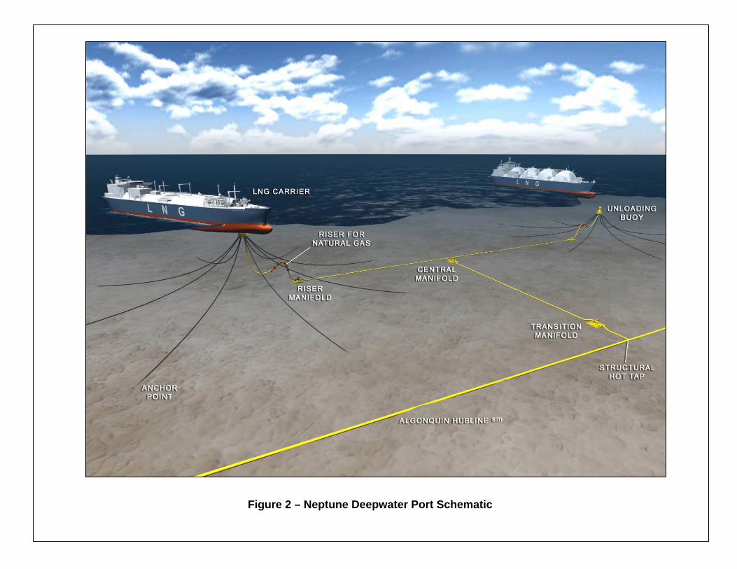
Figure 2 – Neptune Deepwater Port Schematic
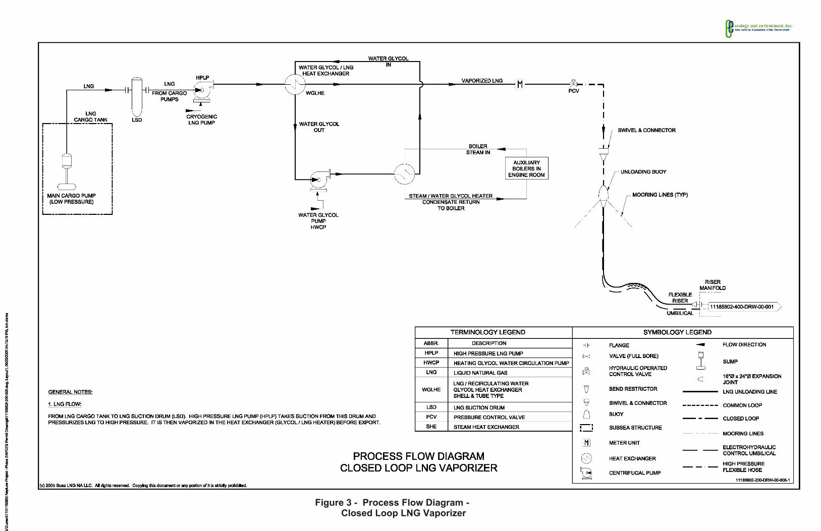
Figure 3 - Process Flow Diagram - Closed Loop LNG Vaporizer
Neptune Deepwater LNG Port NPDES MA0040258 Fact Sheet Page A-1
ATTACHMENT A
Summary of Essential Fish Habitat (EFH) Designation
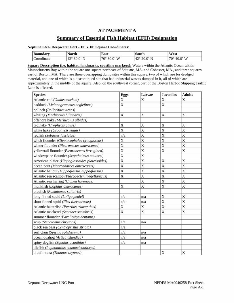
Neptune LNG Deepwater Port - 10’ x 10’ Square Coordinates:
Boundary North East South West Coordinate 42° 30.0’ N 70° 30.0’ W 42° 20.0’ N 70° 40.0’ W
Square Description (i.e. habitat, landmarks, coastline markers): Waters within the Atlantic Ocean within Massachusetts Bay within the square one square northeast of Scituate, MA. and Cohasset, MA., and three squares east of Boston, MA. There are three overlapping dump sites within this square, two of which are for dredged material, and one of which is a discontinued site that had industrial wastes dumped in it, all of which are approximately in the middle of the square. Also, on the southwest corner, part of the Boston Harbor Shipping Traffic Lane is affected.
Species Eggs Larvae Juveniles Adults Atlantic cod (Gadus morhua) X X X X haddock (Melanogrammus aeglefinus) X X pollock (Pollachius virens) whiting (Merluccius bilinearis) X X X X offshore hake (Merluccius albidus) red hake (Urophycis chuss) X X X X white hake (Urophycis tenuis) X X X X redfish (Sebastes fasciatus) n/a X X X witch flounder (Glyptocephalus cynoglossus) X X X X winter flounder (Pleuronectes americanus) X X X X yellowtail flounder (Pleuronectes ferruginea) X X X X windowpane flounder (Scopthalmus aquosus) X X American plaice (Hippoglossoides platessoides) X X X X ocean pout (Macrozoarces americanus) X X X X Atlantic halibut (Hippoglossus hippoglossus) X X X X Atlantic sea scallop (Placopecten magellanicus) X X X X Atlantic sea herring (Clupea harengus) X X X monkfish (Lophius americanus) X X X X bluefish (Pomatomus saltatrix) long finned squid (Loligo pealei) n/a n/a X X short finned squid (Illex illecebrosus) n/a n/a X X Atlantic butterfish (Peprilus triacanthus) X X X X Atlantic mackerel (Scomber scombrus) X X X X summer flounder (Paralicthys dentatus) scup (Stenotomus chrysops) n/a n/a black sea bass (Centropristus striata) n/a surf clam (Spisula solidissima) n/a n/a ocean quahog (Artica islandica) n/a n/a spiny dogfish (Squalus acanthias) n/a n/a tilefish (Lopholatilus chamaeleonticeps) bluefin tuna (Thunnus thynnus) X X