Embed Size (px)
Citation preview
Concentration-Gradient Stabilization with Segregated Counter- and Co-Ion Paths:A Quasistationary Depletion Front for Robust Molecular Isolation or Concentration
Gongchen Sun, Zehao Pan, Satyajyoti Senapati, and Hsueh-Chia Chang*
Department of Chemical and Biomolecular Engineering, University of Notre Dame,Notre Dame, Indiana 46556, USA
(Received 8 September 2016; revised manuscript received 28 April 2017; published 16 June 2017)
We study the spatiotemporal dynamics of a microfluidic system with a nonselective microfluidic channelgated by an ion-selective membrane which separates the ion flux paths of cations and anions. To preserveelectroneutrality, the ionic concentration in the system is shown to converge to a specific inhomogeneousdistribution with robust constant current fluxes. A circuit scaling theory that collapses measured asymptoticcurrents verifies that this is a generic and robust mechanism insensitive to channel geometry, ion selectivity,and electrolyte ionic strength. This first temporally stationary but spatially inhomogeneous depletion frontcan be used for modulating ionic current and for isotachophoretic isolation of low-mobility molecules andexosomes on small diagnostic chips for various medical applications that require robust high-throughputand integrated platforms.
DOI: 10.1103/PhysRevApplied.7.064024
I. INTRODUCTION
The spatiotemporal dynamics of ions and currents in amicrofluidic system with adjoining ion-selective media haslong been suspected to be driven by the electroneutralityconstraint. Without electric-field or current penetrationthrough the channel walls or the ion-selective media, thefield lines and the current lines within a system are identical[1]. Both cations and anions share the same flux lines,though in opposite directions. The net tangential cation andanion fluxes remain the same at every position along thefield line and cancel each other out. This flux invariancecondition can be specified by the same local tangentialelectric field along the field or current lines with a spatiallyhomogeneous electrolyte concentration field [1]. Thus,electroneutrality can be preserved without spatial inhomo-geneity. However, if an ion-selective membrane separates theflux lines of different ions, or if there is field leakage throughthe wall [2], the field lines separate from the current lines,which then segregate into two distinct cation and anion fluxlines. Under this condition, flux invariance along differentfield lines cannot be achieved for both ions if the systemremains spatially homogeneous. Hence, electroneutralitynecessarily requires spatial inhomogeneity for such systemswith ion-selective media. In his seminal monograph,Rubinstein [3] shows that a diffusion layer with a nonuni-form ionic strength appears on one side of an ion-selectivemembrane under a voltage bias to preserve electro neutrality.A recent analysis by Yariv and Almog [4] (which generalizesthe analysis of Ben and Chang [5] of the diffusive currenttowards the ion-selective membrane) attributes a memory
effect in the ion-concentration-polarization dynamics toelectroneutrality.On the other hand, spatially inhomogeneous ion con-
centration polarization is used in many existing biomedi-cal applications and has been suggested for future ones.Examples in current biotechnology include isoelectricfocusing, isotachophoresis, and field-flow fractionation.Ion current rectification across a conic nanopore wasrecently attributed to a gradient of the mobile ionconcentration along the pore [6]. This phenomenon couldlead to artificial biomimetic ion channels for control andquantification of specific ions or molecules [7]. Indeed,microfluidic chips with integrated perm-selective mem-brane modules have been designed to produce on-chipconcentration gradients for the control and analysis ofmacromolecules, such as the transport, concentration, andidentification of protein and nucleic-acid biomarkers forautonomous liquid-biopsy platforms in precision medicine[8]. Low concentrations and mobility of these biomarkersrequire an on-chip analytical system that can isolate themolecules in a short channel. Recent biosensor work [9]shows that the ionic strength jump across a depletion frontgenerated by an ion-selective membrane can be used forthe isotachophoretic isolation of molecules, exosomes,and nanoparticles. A common problem in all of theseon-chip depletion-front technologies is that, without thepresence of large reservoirs, the on-chip inhomogeneousconcentration profile is highly dynamic and unstable.A stationary ionic-strength inhomogeneity (a stationarydepletion front) that does not require pairing of electro-lytes with different salts or pH can produce robustisotachophoretic and isoelectric purification and isolationplatforms for low-mobility analytes in a short channel orbiochip.
*Corresponding [email protected]
PHYSICAL REVIEW APPLIED 7, 064024 (2017)
2331-7019=17=7(6)=064024(7) 064024-1 © 2017 American Physical Society
This concentration depletion front is governed by thediffusion equation and can propagate to infinity (or the endof the channel) without reaching a steady state [10]. Currentwork focuses on using a counter bulk flow, such as anelectro-osmotic flow or convective mixing [9,11–15], tobalance the advance of the depletion front. However, thecounter bulk flow will likely weaken the necessary inho-mogeneity and cause dispersion of the analyte. Meanwhile,most counter-bulk-flow methods, such as those usingan electro-osmotic flow, are effective only in shallowmicrochannels (a few micrometers) and cannot allowhigh-throughput processing of multiple samples in manymedical applications.In this paper, we report a particular coupled-gating
geometry between two different ionic paths in a micro-fluidic chip that can drive the depletion front from anion-selective membrane to a quasistationary position byusing only the eletroneutrality constraint and withoutintroducing a counter bulk flow. The spatial inhomogeneityof the ion concentration in the microchannel stays stablewhen the transmembrane potential drop and current vanish.This strategy of establishing a quasistationary depletionfront can potentially be used to design on-chip isotacho-phoretic and isoelectric sample-pretreatment modules inintegrated medical diagnostic platforms.
II. FABRICATION AND EXPERIMENTALMETHODS
Our system with two different ionic paths consists of anonselective microfluidic channel that allows both cationand anion electromigration fluxes and an anion-exchangemembrane (AEM) that allows only counterion (anion)fluxes. These two ionic paths, one ion selective and onenonselective, intersect perpendicularly, as illustrated inFig. 1(a), and the fluxes are driven by three electrodes: agating electrode G outside the membrane and a drain-source (D-S) pair in the cross-channel. These two ionicpaths share a common section within the microfluidicchannel [Fig. 1(a)]. As a result of this coupling, the chargeflux through the selective AEM can be arrested to preserveelectroneutrality if the voltage in the shared sectionVmembrane approaches the gating voltage Vg. Once thecharge flux through the membrane is arrested, the depletionfront stops propagating at a quasistationary position.In order to prove that our quasistationary depletion front
is robust in different microfluidic systems, we fabricatetwo kinds of hybrid ionic path devices with differentgeometrical parameters: an AEM-based polycarbonate(PC) microfluidic chip and an AEM-based polydimethyl-siloxane (PDMS) microfluidic chip.The AEM-based PC microfluidic chip consists of three
layers of PC sheets, and microchannels are structured bycutting the middle PC sheet on a plotter (Graphtec CuttingPro FC7000MK2-60). The openings of microchannels forfluidic connections and membrane attachment are cut on
the top PC sheet. These three structured PC sheets are thenaligned and thermally bonded together at 170 °C for30 min. Channels with two different dimensions arefabricated: 2 mmwide × 28 mm long × 250 μmhigh and1 mmwide × 28 mm long × 250 μm high to study thearrest of the depletion front in different nonselective ionicpaths discussed later in this paper. Cut pipette tips with afilter paper at the bottom as buffer reservoirs for electricalconnection and Tygon tubings as fluidic inlets and outletsare fixed by an UV curable glue (Acrifix 192) onto theirdesignated places on the top PC sheet. A layer of 1%agarose gel is placed on the bottom of each cut pipette-tipreservoir to prevent possible bubble entry and to suppresselectro-osmotic flows during electrical measurements. A1 × 10 mm AEM strip (Mega a.s., Czech Republic) is cutand embedded in the membrane opening on the top PCsheet to cover the microfluidic channel at the designatedposition. The last step to complete the device is to fix andseal the membrane strip with the UV curable glue, makingthe membrane closely attached on top of the microfluidicchannel and connecting two separated microchannels: oneis used as the nonselective ionic path shown in Fig. 1(a),and the other one to apply gating voltage on the other side
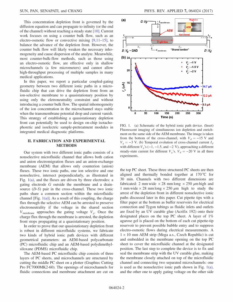
FIG. 1. (a) Schematic of the hybrid ionic path device. (Inset)Fluorescent imaging of simultaneous ion depletion and enrich-ment on the same side of the AEMmembrane. The image is takenfrom the bottom of the cross-channel, with Vd ¼ −15 V andVg ¼ −3 V. (b) Temporal evolution of cross-channel current Idwith different Vg’s (−1, −1.5, and −2 V), approaching a differentsteady-state current for different Vg’s. Vd ¼ −20 V in all threeexperiments.
SUN, PAN, SENAPATI, and CHANG PHYS. REV. APPLIED 7, 064024 (2017)
064024-2
of the membrane. The AEM-based PC microfluidic chipsare used in experiments shown in Fig. 4.The AEM-based PDMS microfluidic chip is fabricated
using the PDMS casting method against a glass-tape-membrane master of fluidic structures. A layer ofdouble-sided Kapton tape with a 100-μm thickness is cutwith the plotter and then transferred onto a precleaned glasssubstrate as the channel mold. The mold defines a channelwith the dimensions 2 mmwide × 28 mm long × 100 μmhigh as the nonselective ionic path. A 1 × 10 mm AEMstrip is fixed onto the double-sided-tape mold at thedesignated place. Similarly, the membrane strip connectstwo channels: one channel as the nonselective ionic pathand the other one for gating-voltage application. Siliconetubings for both fluidic inlets and outlets and electricalconnections are positioned onto the double-sided-tapemold to complete the casting master. A PDMS prepolymer(Sylgard 184) is prepared by mixing the base and the curingagent in a weight ratio of 10∶1 and is degassed in vacuumfor 15 min. The PDMS prepolymer is then poured onto thecompleted master and degassed again. The whole structureis cured in an oven at 70 °C or 50 min. The cured PDMScast is peeled off and bonded onto a precleaned glass slideusing corona discharge followed by thermal bonding at70 °C for 2 h to complete the device. Both devices are filledwith 10-mM potassium chloride (KCl) solution for 48 h tolet the AEM swell properly prior to use. The AEM-basedPDMSmicrofluidic chips are used in experiments shown inFigs. 1–4.To understand the dynamics of establishing the stationary
depletion front, we perform a two-channel chronoamper-ometry experiment on both microfluidic systems with real-time fluorescence imaging. A 10-mM KCl solution is usedas the electrolyte in all electrical characterizations. Externalvoltages are applied through platinumwires on theG,D, andS ends [Fig. 1(a)] of the microfluidic system simultaneously.In each measurement, the transmembrane current Imembranemeasured from the G end and the cross-channel current Idmeasured from the D end are recorded for over 300 s by aKeithley 2636A Dual-Channel System SourceMeterInstrument. The gated and normalized ionic resistance ofthe cross-channel is subsequently calculated from the steady-state Id. To visualize the ion-concentration-polarizationregion, we use 100 μM cationic Rhodamine 6G dyedissolved in a 10-mM KCl solution as a fluorescenceindicator without changing the conductivity of the buffer.The visualization process is performed on a customizeddark-room platform equipped with a Dark ReaderTransilluminator (Clare Chemical) to excite the fluorescentdye from the top of the microfluidic chip. Fluorescenceimages are taken from the bottom of the microfluidic chip bya QImaging Retiga 2000R Fast 1394 camera synchronizedwith the Keithley SourceMeter Instrument through a customMATLAB code.
III. RESULTS AND DISCUSSION
We assign the S end of the cross-channel as the electric-potential reference point (GND) and set a constant negativevoltage Vd at the D end of the cross-channel to electro-phoretically drive ion fluxes through the nonselective ionicpath. By properly applying a negative potential Vg
(between GND and Vd) at the G end of the anion-selectivepath, an ion depletion zone and an ion enrichment zone canbe generated simultaneously in the cross-channel [16]. Thedynamics towards an electroneutral state, with vanishingtransmembrane current [Fig. 2(c)], involve equilibration ofthe voltage Vmembrane that is at the junction of the two ionicpaths [the shared section in Fig. 1(a)] towards Vg. Theadjustment of Vmembrane during the equilibration resultsfrom propagation of the depletion front towards a specificlocation at the D end of the cross-channel. Unlike ahomogeneous electrolyte, which usually produces a linearelectric potential profile along the channel, this depletionamplifies the ionic resistance and redistributes the electricpotential along the cross-channel until Vmembrane ¼ Vg.In the actual device, due to the finite width of the AEM,
the local value of Vmembrane varies slightly along the interfacebetween the membrane and the cross-channel when thedepletion front approaches the specific location. Althoughthe net transmembrane current across the membrane van-ishes in the normal direction, such a tangential potentialdifference of Vmembrane results in a tangential cross-membrane anion flux which enters the AEM from the leftside of the cross-channel and exits to the right side. Theestablished depletion zone to the right (the D side) of themembrane can hence be maintained. However, this tangen-tial cross-membrane anion flux is much smaller than theoriginal transmembrane flux, with far smaller space-chargecreation and anion depletion rates. As seen in the fluores-cence image inset of Fig. 1(a), simultaneous ion enrichmentto the left and depletion to the right occur on the channel sideof the gating membrane, supporting the development of atangential cross-membrane anion flux entering and exitingthe finite-width membrane without penetration [17]. Thistangential anion flux across the membrane sustains thedepletion-front position but not its original front speed.Figure 1(b) shows the cross-channel current evolution
with Vd set at −20 V but with different Vg’s ranging from−1 to −2 V. Id approaches different steady-state values fordifferent Vg’s with slight variations at the end of all threeexperiments, indicating that the depletion front stabilizesand the cross-channel ionic resistance approaches specificvalues. The slight variation in current is due to a weakvortex instability developed on the depletion side of themembrane. However, by designing the cross-channel wallparallel to the AEM with a small separation (100 μm) [10],we are able to suppress the vortex instability so that it doesnot arrest the depletion growth and disturb the stabilizationof the cross-channel current.
CONCENTRATION-GRADIENT STABILIZATION WITH … PHYS. REV. APPLIED 7, 064024 (2017)
064024-3
For an unbounded symmetric electrolyte without twosegregated current paths, the depletion front from an ion-selective membrane advances rapidly to infinity with auniversal self-similar diffusive scaling
ffiffiffiffiffiffi
Dtp
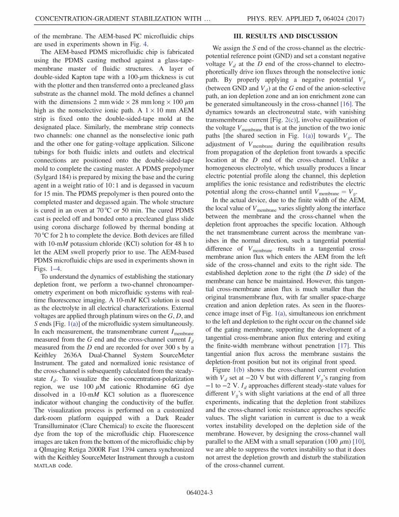
[18]. However,the tracking of the instantaneous length of the ion depletionregion Ldep (by low intensity of the cationic fluorescenceindicator) in our system with two different ionic paths(Vg ¼ −2.5 V and Vd ¼ −15 V) indicates that initialdiffusive dynamics develop into a slow nondiffusive one[Fig. 2(a)] at the same time when Id approaches steadystate. The fact that the initial depletion-front evolutionfollows the self-similar diffusive scaling indicates that thehydrodynamic vortex instabilities and convections aresuppressed. However, the deviation of depletion growthfrom the diffusive scaling after 90 s [Fig. 2(b)] suggeststhat the depletion front ceases to advance rapidly andapproaches a stationary position to suppress space-chargecreation. The cationic fluorescent dyes can only migratelinearly with a limited electrophoretic mobility, when theyenter the homogeneous low-electric-field region beyond thequasistationary depletion front after t ¼ 90 s. The arrestedconcentration polarization region is about 20 mm awayfrom the D end of the channel, far from the end boundary.The movie which shows the real-time growth and arrest ofthe depletion front can be found in the Supplemental
Material [19]. Owing to the negative surface charges ofthe PDMS microchannel [20], electro-osmotic flow may begenerated at the cross-channel during the growth of thedepletion front. In order to suppress net electro-osmoticconvection, we seal the end tubings for electric connectionsat both the S end and theD end of the cross-channel by glue[10]. The closed microchannel encapsulates the electrolyteand hence suppresses net electro-osmotic convections oramplified electrokinetic flows [21]. A pair of vortices dueto a weak backflow from the D end can still be observed inFig. 2(a) and causes small fluctuations in the cross-channelcurrent [Fig. 2(c)]. We can further eliminate the electro-osmotic instability by chemically modifying the PDMSmicrochannels to remove surface charges [22], or by fillingthe microchannel with hydrogels to block the flow [9].The currents through these two ionic paths during the
process of the depletion-region evolution are measuredsimultaneously [shown in Fig. 2(c)]. As a result of thenegative feedback from the depletion growth, Vmembraneapproaching Vg renders the current flowing through theAEM anion-selective path, Imembrane, to cease to zero after90 s, which corresponds to a vanishing of the fast charge-generating counterion flux to preserve electroneutrality.Subsequently, the current through the nonselective ionicpath approaches a steady-state value ( 8.6 μA, in this case),
FIG. 2. (a) Fluorescence images of the depletion front at the indicated times. (b) Time evolution of the instantaneous depletion-regionlength. Also depicted is the (
ffiffiffiffiffiffi
Dtp
) scaling as a continuous line. A clear break from the self-similar scaling of the depletion-length growthis observed after 90 s. (c) The charge-generating counterion flux through the AEM (Imembrane) decreases to zero after 90 s.Correspondingly, the cross-channel current Id approaches a steady-state value beyond that time. Vd ¼ −15 V and Vg ¼ −2.5 V in theexperiment. The inset shows that the transmembrane current Imembrane becomes unstable at Vg ¼ 0 V and Vd ¼ −20 V. Imembrane cannotvanish to maintain system electroneutrality since the voltage in the cross-channel across the membrane cannot reach the zero gatingvoltage.
SUN, PAN, SENAPATI, and CHANG PHYS. REV. APPLIED 7, 064024 (2017)
064024-4
as the ionic resistance of the cross-channel approaches aspecific value determined by the ion concentration pattern.There also exist zero or positive gating voltages that cannever be reached by the voltage field in the cross-channel.Shown in the inset of Fig. 2(c), the transmembrane currentImembrane does not vanish when the gating voltage Vg is setto 0 V. Hence, the electroneutrality in the system can neverbe met, resulting in the space-charge generation that candrive charging and discharging events, which are observedin the unstable Imembrane after 250 s in the Fig. 2(c) inset.A series of experimental data correlating the steady-state
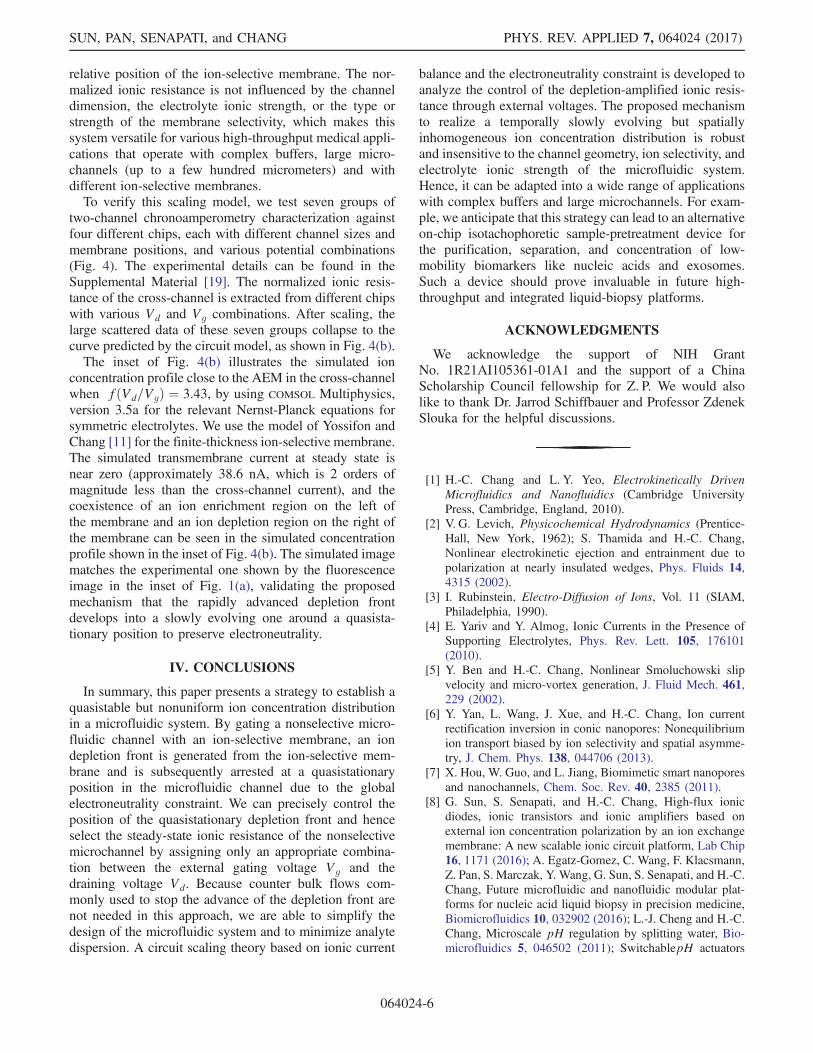
ionic resistance of the cross-channel with the quasista-tionary depletion length is shown in Fig. 3 for a constant Vd(−15V) but a Vg that varies from −0.5 to −3 V. Thedepletion length Ldep is extracted from the fluorescenceimage when the cross-channel current first reaches thesteady-state value. The depletion-amplified ionic resistanceRcross-channel is compared with the original ionic resistanceof the cross-channel without any gating effect, which iscalculated based on the channel geometry and the initialhomogeneous electrolyte condition (Fig. 3), showing theincrease of the ionic resistance due to the low mobile-ionconcentration within the depletion region. The consistenttrend between Rcross-channel and Ldep versus Vg clearlyconfirms that the ionic resistance of the nonselective ionicpath is modulated by the gating potential through thespecific selection of the depletion length.Equilibration ofVmembrane andVg at steady state allows us
to develop a simple scaling theory for the cross-channelresistance. Through ionic current balance ½ðVs − VgÞ=Rs� ¼½ðVg − VdÞ=Rd�, and given that the cross-channelRcross-channel ¼ Rs þ Rd, we then have Rcross-channel ¼ðVd=VgÞRs. We define the length ratio between the distancefrom the S end to the AEM and the entire cross-channellength asf, so that the ratio betweenRs and the original ionicresistance of the cross-channel is also f. Here, we neglect theenrichment effect on the left side of the membrane since,
under our voltage relationship, we expect that the enrich-ment does not affect the ionic resistance as strongly as thedepletion in the shared section. We can then normalize theRcross-channel by the original ionic resistance of the cross-channel without any gating. So the normalized depletion-amplified ionic resistance Rcross-channel ¼ f ðVd=VgÞ. For agiven channel design, the amplification of the ionic resis-tance of the nonselective cross-channel at steady statedepends only on the ratio of the applied voltages and the
FIG. 3. The ionic resistance of the cross-channel shows strongcorrelation with the depletion-region length and the gatingvoltage Vg. Vd ¼ −15 V in all experiments.
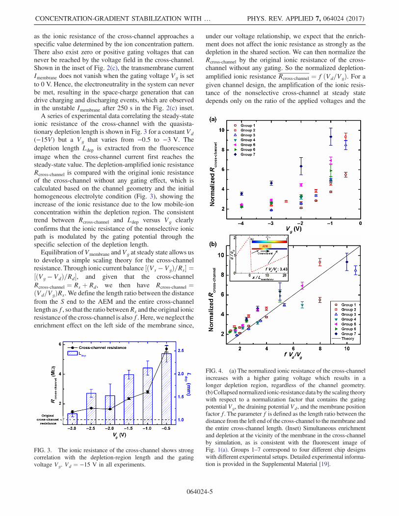
FIG. 4. (a) The normalized ionic resistance of the cross-channelincreases with a higher gating voltage which results in alonger depletion region, regardless of the channel geometry.(b) Collapsed normalized ionic-resistance data by the scaling theorywith respect to a normalization factor that contains the gatingpotential Vg, the draining potential Vd, and the membrane positionfactor f. The parameter f is defined as the length ratio between thedistance from the left end of the cross-channel to themembrane andthe entire cross-channel length. (Inset) Simultaneous enrichmentand depletion at the vicinity of the membrane in the cross-channelby simulation, as is consistent with the fluorescent image ofFig. 1(a). Groups 1–7 correspond to four different chip designswith different experimental setups. Detailed experimental informa-tion is provided in the Supplemental Material [19].
CONCENTRATION-GRADIENT STABILIZATION WITH … PHYS. REV. APPLIED 7, 064024 (2017)
064024-5
relative position of the ion-selective membrane. The nor-malized ionic resistance is not influenced by the channeldimension, the electrolyte ionic strength, or the type orstrength of the membrane selectivity, which makes thissystem versatile for various high-throughput medical appli-cations that operate with complex buffers, large micro-channels (up to a few hundred micrometers) and withdifferent ion-selective membranes.To verify this scaling model, we test seven groups of
two-channel chronoamperometry characterization againstfour different chips, each with different channel sizes andmembrane positions, and various potential combinations(Fig. 4). The experimental details can be found in theSupplemental Material [19]. The normalized ionic resis-tance of the cross-channel is extracted from different chipswith various Vd and Vg combinations. After scaling, thelarge scattered data of these seven groups collapse to thecurve predicted by the circuit model, as shown in Fig. 4(b).The inset of Fig. 4(b) illustrates the simulated ion
concentration profile close to the AEM in the cross-channelwhen fðVd=VgÞ ¼ 3.43, by using COMSOL Multiphysics,version 3.5a for the relevant Nernst-Planck equations forsymmetric electrolytes. We use the model of Yossifon andChang [11] for the finite-thickness ion-selective membrane.The simulated transmembrane current at steady state isnear zero (approximately 38.6 nA, which is 2 orders ofmagnitude less than the cross-channel current), and thecoexistence of an ion enrichment region on the left ofthe membrane and an ion depletion region on the right ofthe membrane can be seen in the simulated concentrationprofile shown in the inset of Fig. 4(b). The simulated imagematches the experimental one shown by the fluorescenceimage in the inset of Fig. 1(a), validating the proposedmechanism that the rapidly advanced depletion frontdevelops into a slowly evolving one around a quasista-tionary position to preserve electroneutrality.
IV. CONCLUSIONS
In summary, this paper presents a strategy to establish aquasistable but nonuniform ion concentration distributionin a microfluidic system. By gating a nonselective micro-fluidic channel with an ion-selective membrane, an iondepletion front is generated from the ion-selective mem-brane and is subsequently arrested at a quasistationaryposition in the microfluidic channel due to the globalelectroneutrality constraint. We can precisely control theposition of the quasistationary depletion front and henceselect the steady-state ionic resistance of the nonselectivemicrochannel by assigning only an appropriate combina-tion between the external gating voltage Vg and thedraining voltage Vd. Because counter bulk flows com-monly used to stop the advance of the depletion front arenot needed in this approach, we are able to simplify thedesign of the microfluidic system and to minimize analytedispersion. A circuit scaling theory based on ionic current
balance and the electroneutrality constraint is developed toanalyze the control of the depletion-amplified ionic resis-tance through external voltages. The proposed mechanismto realize a temporally slowly evolving but spatiallyinhomogeneous ion concentration distribution is robustand insensitive to the channel geometry, ion selectivity, andelectrolyte ionic strength of the microfluidic system.Hence, it can be adapted into a wide range of applicationswith complex buffers and large microchannels. For exam-ple, we anticipate that this strategy can lead to an alternativeon-chip isotachophoretic sample-pretreatment device forthe purification, separation, and concentration of low-mobility biomarkers like nucleic acids and exosomes.Such a device should prove invaluable in future high-throughput and integrated liquid-biopsy platforms.
ACKNOWLEDGMENTS
We acknowledge the support of NIH GrantNo. 1R21AI105361-01A1 and the support of a ChinaScholarship Council fellowship for Z. P. We would alsolike to thank Dr. Jarrod Schiffbauer and Professor ZdenekSlouka for the helpful discussions.
[1] H.-C. Chang and L. Y. Yeo, Electrokinetically DrivenMicrofluidics and Nanofluidics (Cambridge UniversityPress, Cambridge, England, 2010).
[2] V. G. Levich, Physicochemical Hydrodynamics (Prentice-Hall, New York, 1962); S. Thamida and H.-C. Chang,Nonlinear electrokinetic ejection and entrainment due topolarization at nearly insulated wedges, Phys. Fluids 14,4315 (2002).
[3] I. Rubinstein, Electro-Diffusion of Ions, Vol. 11 (SIAM,Philadelphia, 1990).
[4] E. Yariv and Y. Almog, Ionic Currents in the Presence ofSupporting Electrolytes, Phys. Rev. Lett. 105, 176101(2010).
[5] Y. Ben and H.-C. Chang, Nonlinear Smoluchowski slipvelocity and micro-vortex generation, J. Fluid Mech. 461,229 (2002).
[6] Y. Yan, L. Wang, J. Xue, and H.-C. Chang, Ion currentrectification inversion in conic nanopores: Nonequilibriumion transport biased by ion selectivity and spatial asymme-try, J. Chem. Phys. 138, 044706 (2013).
[7] X. Hou, W. Guo, and L. Jiang, Biomimetic smart nanoporesand nanochannels, Chem. Soc. Rev. 40, 2385 (2011).
[8] G. Sun, S. Senapati, and H.-C. Chang, High-flux ionicdiodes, ionic transistors and ionic amplifiers based onexternal ion concentration polarization by an ion exchangemembrane: A new scalable ionic circuit platform, Lab Chip16, 1171 (2016); A. Egatz-Gomez, C. Wang, F. Klacsmann,Z. Pan, S. Marczak, Y. Wang, G. Sun, S. Senapati, and H.-C.Chang, Future microfluidic and nanofluidic modular plat-forms for nucleic acid liquid biopsy in precision medicine,Biomicrofluidics 10, 032902 (2016); L.-J. Cheng and H.-C.Chang, Microscale pH regulation by splitting water, Bio-microfluidics 5, 046502 (2011); SwitchablepH actuators
SUN, PAN, SENAPATI, and CHANG PHYS. REV. APPLIED 7, 064024 (2017)
064024-6
and 3D integrated salt bridges as new strategies forreconfigurable microfluidic free-flow electrophoretic sepa-ration, Lab Chip 14, 979 (2014).
[9] J. Quist, K. G. H. Janssen, P. Vulto, T. Hankemeier, and H. J.van der Linden, Single-electrolyte isotachophoresis using ananochannel-induced depletion zone, Anal. Chem. 83, 7910(2011); J. Quist, P. Vulto, H. van der Linden, and T.Hankemeier, Tunable ionic mobility filter for depletionzone isotachophoresis, Anal. Chem. 84, 9065 (2012); S.Marczak, S. Senapati, Z. Slouka, and H.-C. Chang, Inducednanoparticle aggregation for short nucleic acid quantifica-tion by depletion isotachophoresis, Biosens. Bioelectron.86, 840 (2016).
[10] H.-C. Chang, G. Yossifon, and E. A. Demekhin, Nanoscaleelectrokinetics and microvortices: How microhydrodynam-ics affects nanofluidic ion flux, Annu. Rev. Fluid Mech. 44,401 (2012).
[11] G. Yossifon and H.-C. Chang, Selection of NonequilibriumOverlimiting Currents: Universal Depletion Layer Forma-tion Dynamics and Vortex Instability, Phys. Rev. Lett. 101,254501 (2008).
[12] B. Zaltzman and I. Rubinstein, Electro-osmotic slip andelectroconvective instability, J. Fluid Mech. 579, 173(2007).
[13] S. J. Kim, Y.-C. Wang, J. H. Lee, H. Jang, and J. Han,Concentration Polarization and Nonlinear ElectrokineticFlow near a Nanofluidic Channel, Phys. Rev. Lett. 99,044501 (2007).
[14] E. V. Dydek, B. Zaltzman, I. Rubinstein, D. S. Deng, A.Mani, and M. Z. Bazant, Overlimiting Current in a Micro-channel, Phys. Rev. Lett. 107, 118301 (2011).
[15] J. H. Lee, Y.-A. Song, and J. Han, Multiplexed proteomicsample preconcentration device using surface-patterned ion-selective membrane, Lab Chip 8, 596 (2008); V. Liu, Y.-A.Song, and J. Han, Capillary-valve-based fabrication of ion-selective membrane junction for electrokinetic samplepreconcentration in PDMS chip, Lab Chip 10, 1485 (2010).
[16] Q. Pu, J. Yun, H. Temkin, and S. Liu, Ion-enrichment andion-depletion effect of nanochannel structures, Nano Lett. 4,1099 (2004).
[17] M. Kim, M. Jia, and T. Kim, Ion concentration polarizationin a single and open microchannel induced by a surface-patterned perm-selective film, Analyst 138, 1370 (2013); M.Jia and T. Kim, Multiphysics simulation of ion concen-tration polarization induced by a surface-patterned nano-porous membrane in single channel devices, Anal. Chem.86, 10365 (2014).
[18] R. J. Hunter, Foundations of Colloid Science, Vol. 2(Clarendon Press, Oxford, 1989).
[19] See Supplemental Material at http://link.aps.org/supplemental/10.1103/PhysRevApplied.7.064024 for ex-perimental details.
[20] B. J. Kirby and E. F. Hasselbrink, Zeta potential of micro-fluidic substrates: 2. Data for polymers, Electrophoresis 25,203 (2004).
[21] S. J. Kim, L. D. Li, and J. Han, Amplified electrokineticresponse concentration polarization near nanofluidic chan-nel, Langmuir 25, 7759 (2009).
[22] Y. Qu, L. A. Marshall, and J. G. Santiago, Simultaneouspurification and fractionation of nucleic acids and proteinsfrom complex samples using bidirectional isotachophoresis,Anal. Chem. 86, 7264 (2014).
CONCENTRATION-GRADIENT STABILIZATION WITH … PHYS. REV. APPLIED 7, 064024 (2017)
064024-7