Embed Size (px)
Citation preview
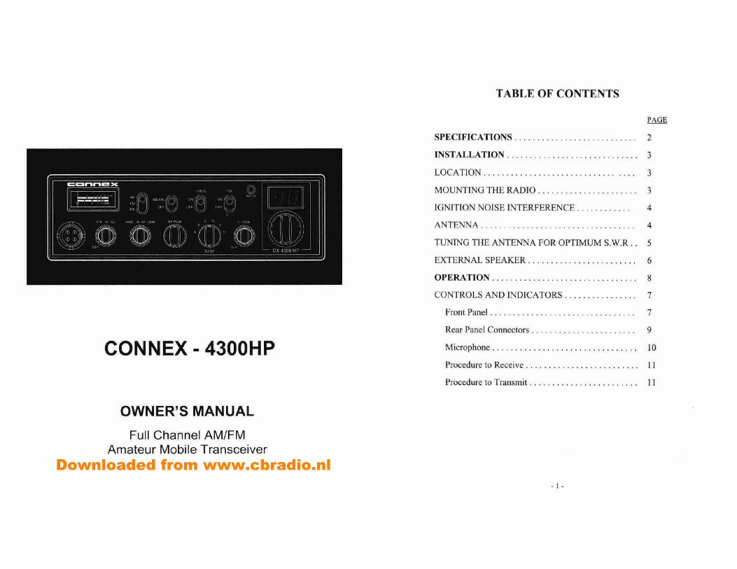
TABLE OF CONTENTS
OWNER'S MANUAL
Full Channel AM/FM Amateur Mobile Transceiver
PAGE
SPECIFICATIONS ........................... 2
INSTALLATION ............................. 3
LOCATION ................................. 3
MOUNTING THE RADIO ...................... 3
IGNITION NOISE INTERFERENCE ............ 4
ANTENNA .................................. 4
TUNING THE ANTENNA FOR OPTIMUM S.W.R.. 5
EXTERNAL SPEAKER ........................
OPERATION ................................ 8
CONTROLS AND INDICATORS ................ 7
Front Panel ................................ 7
Rear Panel Connectors ....................... 9
Microphone ................................ JO
Procedure to Receive ......................... II
Procedure to Transmit ........................ I I
CON NEX - 4300HP
Downloaded from www.cbradio.nl
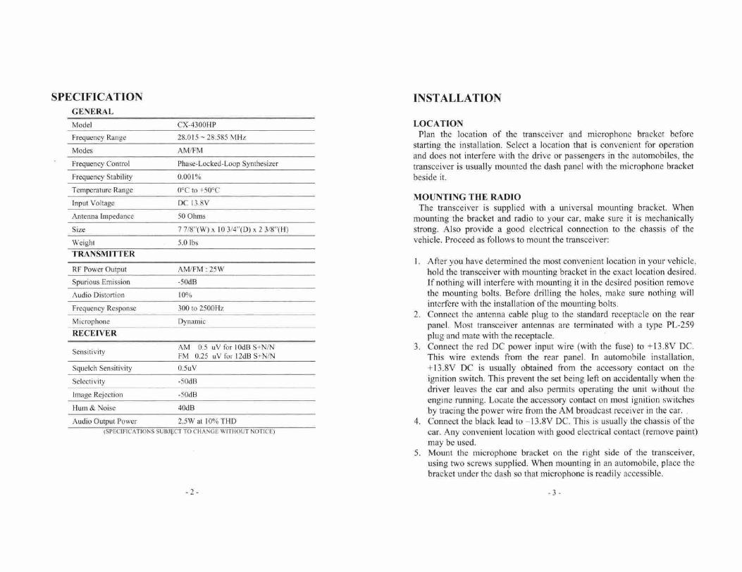
SPECIFICATION
INSTALLATION GENERAL
Model CX-4300HP LOCATION
Frequency Range 28.015 - 28,585 MHz Plan the location of the transceiver 4nd microphone bracket before starting the installation. Select a location that is convenient for operation
Modes AM/FM and does not interfere with the drive or passengers in the automobiles, the
Frequency Control Phase-Locked-Loop Synthesizer transceiver is usually mounted the dash panel with the microphone bracket Frequency Stability 0.001% beside it. Temperature Range 0°C to +50°C
MOUNTING THE RADIO Input Voltage DC 13.8V The transceiver is supplied with a universal mounting bracket. When Antenna Impedance 50 Ohms mounting the bracket and radio to your car, make sure it is mechanically Size 7 7/8"(W) x 10 3/4"(D) x 2 3/8'(H) strong. Also provide a good electrical connection to the chassis of the
Weight 5.0 lbs vehicle. Proceed as follows to mount the transceiver:
TRANSMITTER I. After you have determined the most convenient location in your vehicle,
RF Power Output AM/FM 25W hold the transceiver with mounting bracket in the exact location desired. Spurious Emission -50d13 If nothing will interfere with mounting it in the desired position remove Audio Distortion 10% the mounting bolts. Before drilling the holes, make sure nothing will
Frequency Response 300 to 2500Hz interfere with the installation of the mounting bolts.
2. Connect the antenna cable plug to the standard receptacle on the rear Microphone Dynamic panel. Most transceiver antennas are terminated with a type PL-259 RECEIVER plug and mate with the receptacle.
AM 0.5 uV for 10ct13 S4N/N 3. Connect the red DC power input wire (with the fuse) to +13.8V DC. Setisiti'.tv
FM 025 uV For 12dB S+N/N This wire extends from the rear panel. In automobile installation, Squelch Sensitivity 0.5uV +13.8V DC is usually obtained from the accessory contact on the
Selectivity -50dB ignition switch. This prevent the set being left on accidentally when the driver leaves the car and also permits operating the unit without the
Image Rejection -50dB engine running. Locate the accessory contact on most ignition switches
Hum & Noise 400 by tracing the power wire from the AM broadcast receiver in the car. Audio Output Power 2.5W at 10% TI-ID 4. Connect the black lead to -I 3.8V DC. This is usually the chassis of the
(SPECIFICATIONS SUI3JCT TO CHANGE WITHOUT NOTICE) car. Any convenient location with good electrical contact (remove paint) may be used.
5. Mount the microphone bracket on the right side of the transceiver, using two screws supplied. When mounting in an automobile, place the bracket under the dash so that microphone is readily accessible.
-2- -3-
IGNITION NOISE INTERFERENCE Use of a mobile receiver at low signal levels is normally limited by the
presence of electrical noise. The primary source in automobile installation is from the generator and ignition system in the vehicle. Under most operating conditions, when signal level is adequate. the background noise does not present a serious problem. Also, when extremely low level signals are being received, the transceiver may be operated with vehicles engine turned off. The unit requires very little current and therefore will not significantly discharge the vehicle battery.
In some installation ignition interference may be high enough to make good communications impossible. The electrical noise may come from several sources. Many possibilities exist, as variations between vehicles require different solutions to reduce the noise.
ANTENNA A vertically polarized, quarter-wavelength whip antenna provides the
most reliable operation and greatest range. Shorter, loaded-type whip antennas are more attractive, compact and adequate for applications where the maximum possible distance is not required. Also, loaded whips do not present the problems of high wind resistant imposed by a full quarter-wavelength whip.
Mobile whip antennas utilize the metal body of the vehicle as a ground plane. When mounted at a corner of the vehicle they are slightly directional, in the direction of the body of the vehicle. For all practical purpose, however, the radiation pattern is nondirectional. The slight directional characteristic will be observed only at extreme distances. A standard antenna connector (type So-239) is provided on the transceiver for easy connection to a standard PL-259 cable termination.
If the transceiver is not mounted on a mçtal surface, it is necessary to run a separate ground wire from the unit to good metal electrical ground in the vehicle. When installed in a boat, the transceiver will not operate at maximum efficiency without a ground plate, unless the vessel has a steel hull.
Before installing the transceiver in a boat, consult your dealer for information regarding an adequate grounding system and prevention of electrolysis between fittings in the hull and water.
TUNING THE ANTENNA FOR OPTIMUM S.W.R Since there is such a wide variety of base and mobile antennas, this
section will strictly concern itself to the various types of mobile adjustable antennas. Because the antenna length is directly related to the channel frequency, it must be tuned to resonate optimally on all channels of the transceiver.
Channel I requires a longer antenna than Channel 40 because it is lower in its frequency of operation. Due to the various methods of adjusting antennas for proper S.W.R. we have chosen what we think is the optimum method:
A. Antenna with adjustment screws (set screws). I. Starts with the antenna extended and tighten the set screw lightly
enough so that the antenna can be lightly tapped with your finger for easy adjustment.
2. Set your transceiver to Channel 20. Press the PTT (push-to-talk) switch, and tap the antenna (making it shorter). The S.W.R meter will show a lower reading each time the antenna is lapped. By continuing to shorten the antenna, you will notice the S.W.R reading will reach a low point and then start rising again. This means that you have passed the optimum point for Channel 20.
Extend the antenna a short distance and again follow the procedure above. When the lowest point has been reached, switch to Channel 1 and then to Channel 40 and compare S.W.R readings. They should be almost equal.
B. Antennas which must be cut to proper length I. Follow the same procedure as above but adjust the length by cutting in
1/8" increments until a good match is obtained. 2. Be very careful not to cut too much at one time, as one it is cut, it can
no longer be lengthed.
.4. -5-
3. The whip is easily cut by filing a notch all the way around and breaking the piece off with pliers.
NOTE The proper setting is achieved when the SWR is 1.5 or below, and when it has the same reading for channels land 40.
If you're having difficulties in adjusting your antenna, check the following:
a. All doors must be closed when adjusting the antenna b. Make sure the antenna base is grounded. c. Check your coaxial cable routing (it may be pinched when routed into
the car) d. Try a different location in your car (keeping in mind the radiation
pattern you wish.) e. Is the antenna perfectly vertical? f. Try a different location in your neighborhood. Stay away from large
metal objects when adjusting (metal telephone polls or light post, fences, etc.)
NOTE The transceiver will operate into an SWR of 2 to 1 indefinitely and sustain an SWR of 20 : 1 for a ,naxirnu,n of 5 minutes at rated operating conditions.
EXTERNAL SPEAKER The external speaker jack (EXT SP.) on the rear panel is used for remote
receiver monitoring. The external speaker should have 8 ohms impedance and be able to handle at least 4 watts. When the external speaker is plugged in, the internal speaker is disconnected.
-6-
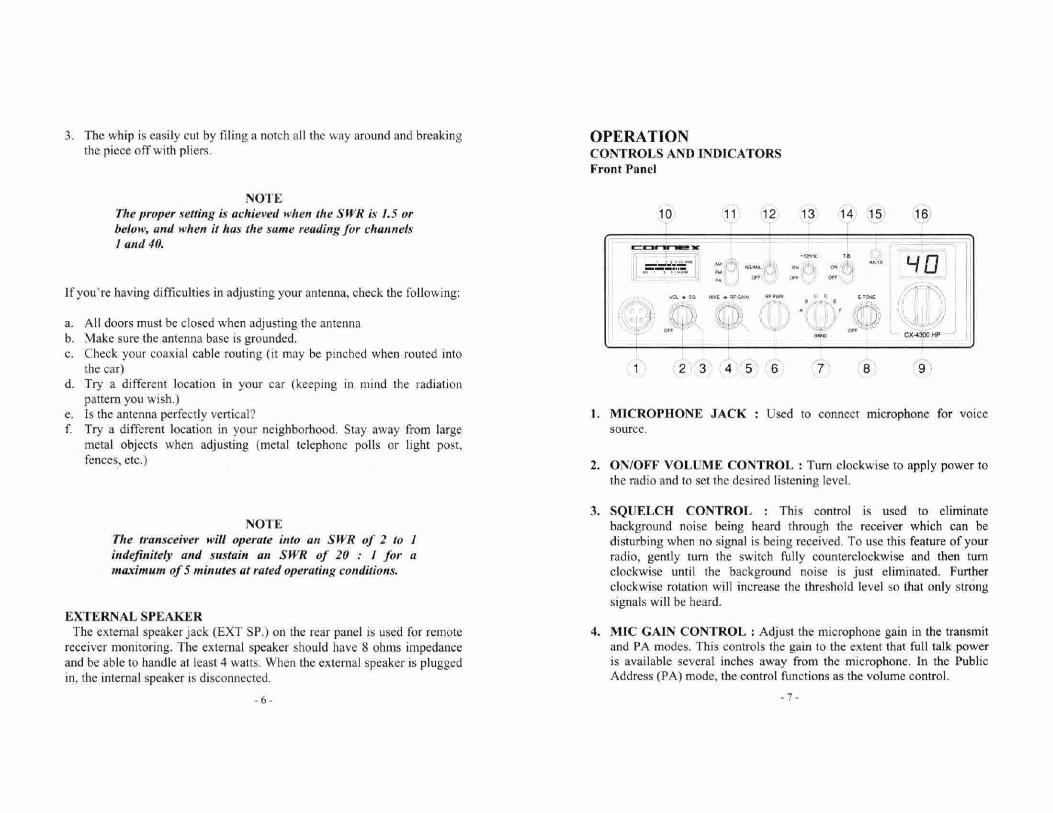
OPERATION CONTROLS AND INDICATORS Front Panel
10 11 12 13 14 15 16
b L/Q
Va 1 go u.K M PW C U (TOC
() I
CX-4300HF
1 23456 7 8 9
1. MICROPHONE JACK Used to connect microphone for voice source.
2. ON/OFF VOLUME CONTROL Turn clockwise to apply power to the radio and to set the desired listening level.
3. SQUELCH CONTROL This control is used to eliminate background noise being heard through the receiver which can be disturbing when no signal is being received. To use this feature of your radio, gently turn the switch fully counterclockwise and then turn clockwise until the background noise is just eliminated. Further clockwise rotation will increase the threshold level so that only strong signals will be heard.
4. MIC GAIN CONTROL Adjust the microphone gain in the transmit and PA modes. This controls the gain to the extent that full talk power is available several inches away from the microphone. In the Public Address (PA) mode, the control functions as the volume control.
-7.
5. RF GAIN CONTROL This control is used to reduce the gain of the RF amplifier under strong signal conditions.
6. RF POWER CONTROL: This control enables adjustment of RF power output continuously up to the rated out power.
7. BAND SELECTOR : This switch selects A. B, C, D, E or F band of operation.
B. E-TONE CONTROL : This control is used for echo effect and intervals of echo sound.
9. CHANNEL SELECTOR : This control is used to select a desired transmit and receive channel.
10. FRONT PANEL METER : The front panel meter allows the user to monitor signal strength and RF output power level.
11. MODE SWITCH : This switch allows you to select one of the following operating modes: AM/FM/PA.
12. NBIANL /OFF SWITCH : In the NBIANL position, the RF Noise Blanker and the automatic Noise Limiter in the audio circuits are also activated, The Noise Blanker is very effective in eliminating repetitive impulse noise such as ignition interference.
13. +10KHzJOFF SWITCH : In the +10KHz position, the transmit and receive frequency is shifted 10KHz up.
14. T.B./OFF SWITCH : This switch is used to monitor the sound feedback effects.
15. TXIRX LED The red LEI) indicates the units is in the transmit mode. The green indicates the units is in the receive mode.
16. CHANNEL DISPLAY : This blue channel display indicates the current selected channel.
-8-
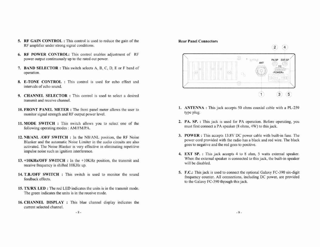
Rear Panel Connectors
2 4
PASP EXT.S ANT
I-c
-POWER,
1 3 5
1. ANTENNA : This jack accepts 50 ohms coaxial cable with a PL-259 type plug.
2. PA. SP. : This jack is used for PA operation. Before operating, you must first connect a PA speaker (8 ohms, 4W) to this jack.
3. POWER : This accepts 13.8V DC power cable with built-in fuse. The power cord provided with the radio has a black and red wire. The black goes to negative and the red goes to positive.
4. EXT SP. : This jack accepts 4 to S ohm, 5 watts external speaker, When the external speaker is connected to this jack, the built-in speaker will be disabled.
5. F.C.: This jack is used to connect the optional Galaxy FC-390 six-digit frequency counter. All connections, including DC power, are provided to the Galaxy FC-390 through this jack.
-9-
PROCEDURE TO RECEIVE AND TRANSMIT
A. MICROPHONE
The receiver and transmitter are controlled by the push-to-talk switch on the microphone. Press the switch and the transmitter is activated, release switch to receive. When transmitting hold the microphone two inch from the mouth and speak clearly in a normal "voice". The transceiver come complete with low-impedance dynamic microphone.
For best result, the user should select a low-impedance dynamic type microphone or a transistorized microphone.
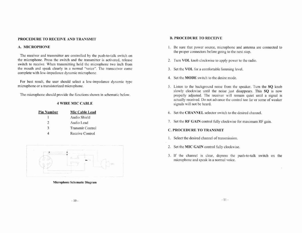
The microphone should provide the functions shown in schematic below.
4 WIRE MIC CABLE
Pin Number Mic Cable Lead Audio Shield
2 Audio Lead
3 Transmit Control 4 Receive Control
4
B. PROCEDURE TO RECEIVE
1. Be sure that power source, microphone and antenna are connected to the proper connectors before going to the next step.
2. Turn VOL knob clockwise to apply power to the radio.
3. Set the VOL for a comfortable listening level.
4. Set the MODE switch to the desire mode.
5. Listen to the background noise from the speaker. Turn the SQ knob slowly clockwise until the noise just disappears. This SQ is now properly adjusted. The receiver will remain quiet until a signal is actually received. Do not advance the control too far or some of weaker signals will not be heard.
6. Set the CHANNEL selector switch to the desired channel.
7. Set the RF GAIN control fully clockwise for maximum RF gain.
C. PROCEDURE TO TRANSMIT
1. Select the desired channel of transmission.
2, Set the MIC GAIN control fully clockwise.
3. If the channel is clear, depress the push-to-talk switch on the microphone and speak in a normal voice.
Microphone Schematic Diagram

ATI48NO3OA