Embed Size (px)
Citation preview
Chapter 5: The Network LayerComputer Networks
Maccabe
Computer Science DepartmentThe University of New Mexico
September 2002

Topics
End-to-end transmission, routing
Design Issues
Routing Algorithms
Congestion Control Algorithms
Quality of Service
Internetworking
The Network Layer in the Internet
Chapter 5 – p.2/117
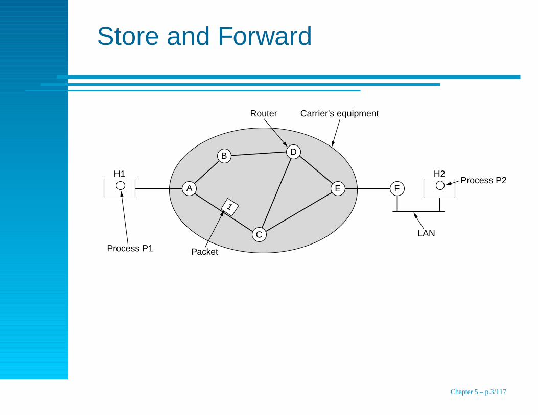
Store and Forward
A E FProcess P2
Packet
LAN
Router Carrier's equipment
Process P1
B
H1 H2
D
C
1
Chapter 5 – p.3/117
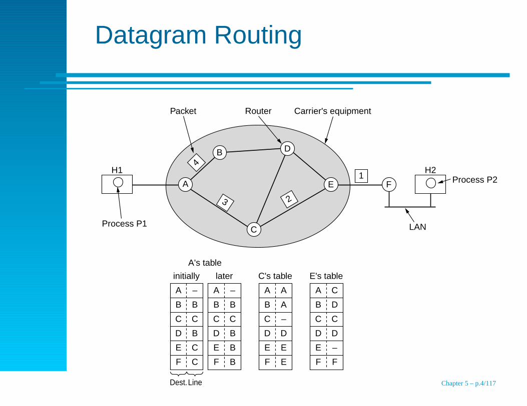
Datagram Routing
A E F Process P2
LAN
Router
1
Carrier's equipment
Process P1
B
H1 H2
D
C
Packet
3
4
2
A –
B B
initially
C C
D B
E C
F C
Dest.
A –
B B
later
A's table
C C
D B
E B
F B
A A
B A
C's table
C –
D D
E E
F E
A C
B D
E's table
C C
D D
E –
F F
Line Chapter 5 – p.4/117
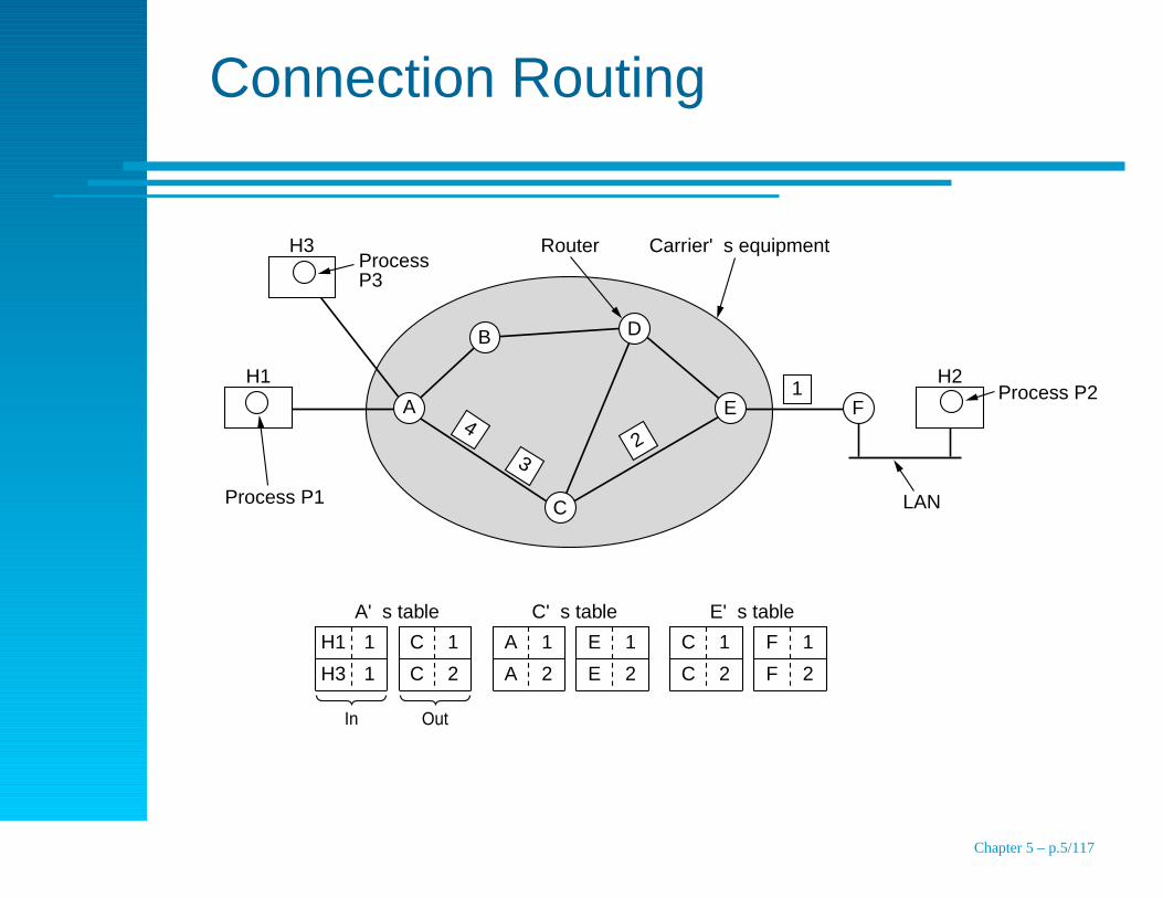
Connection Routing
E FProcess P2
LAN
Router
1
Carrier's equipment
Process P1
Process P3
B
H1
H3
H2
D
C
3
42
H1 1
H3 1
C 1
C 2
A's table
A 1
A 2
E 1
E 2
C's table
C 1
C 2
F 1
F 2
E's table
A
In Out
Chapter 5 – p.5/117

Comparison between Datagram andVirtual-Circuit
Issue Datagram subnet Virtual-circuit subnet
Circuit setup Not needed Required
Addressing Each packet contains the fullsource and destination address
Each packet contains a short VCnumber
State Routers do not hold state informa-tion about connections
Each VC requires router tablespace per connection
Routing Each packet is routed indepen-dently
Route chosen when VC is set up;all packets follow it
Router failures None, except for packets lost dur-ing the crash
All VCs that pass through thefailed router are terminated
Quality of service Difficult Easy if enough resources can beallocated in advance for each VC
Congestion control Difficult Easy if enough resources can beallocated in advance for each VC
Chapter 5 – p.6/117

Topics
End-to-end transmission, routing
Design Issues
Routing Algorithms
Congestion Control Algorithms
Quality of Service
Internetworking
The Network Layer in the Internet
Chapter 5 – p.7/117
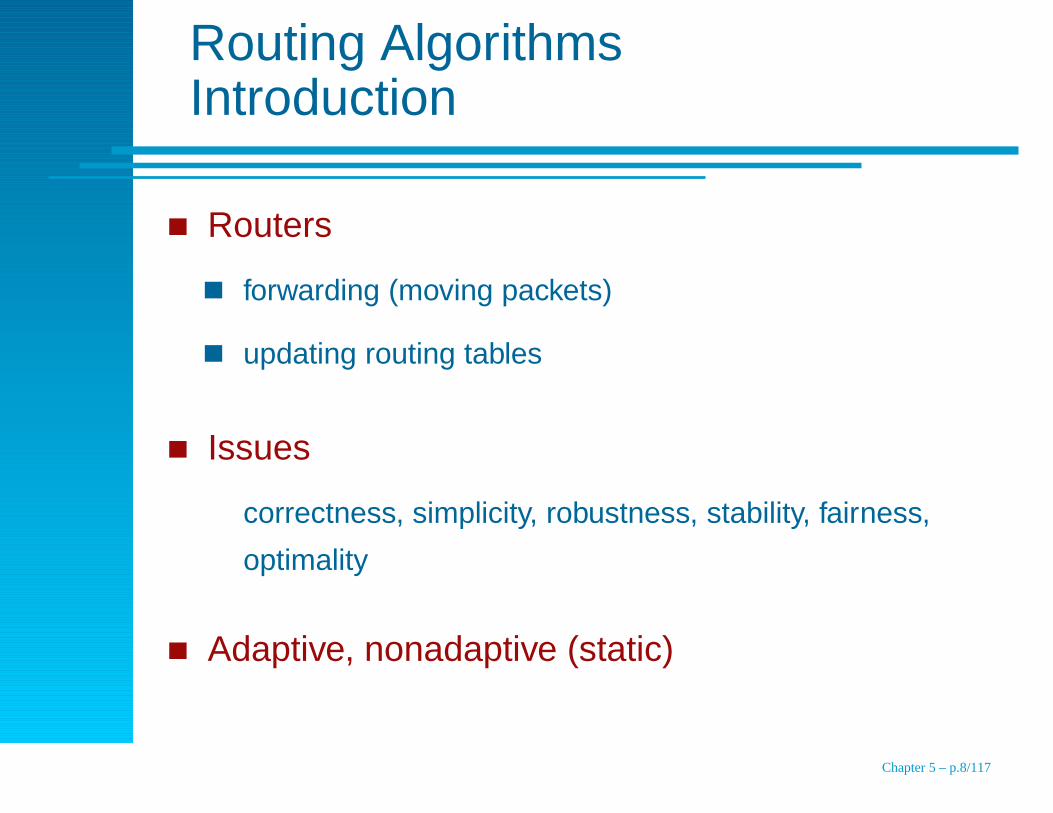
Routing AlgorithmsIntroduction
Routers
forwarding (moving packets)
updating routing tables
Issues
correctness, simplicity, robustness, stability, fairness,
optimality
Adaptive, nonadaptive (static)
Chapter 5 – p.8/117
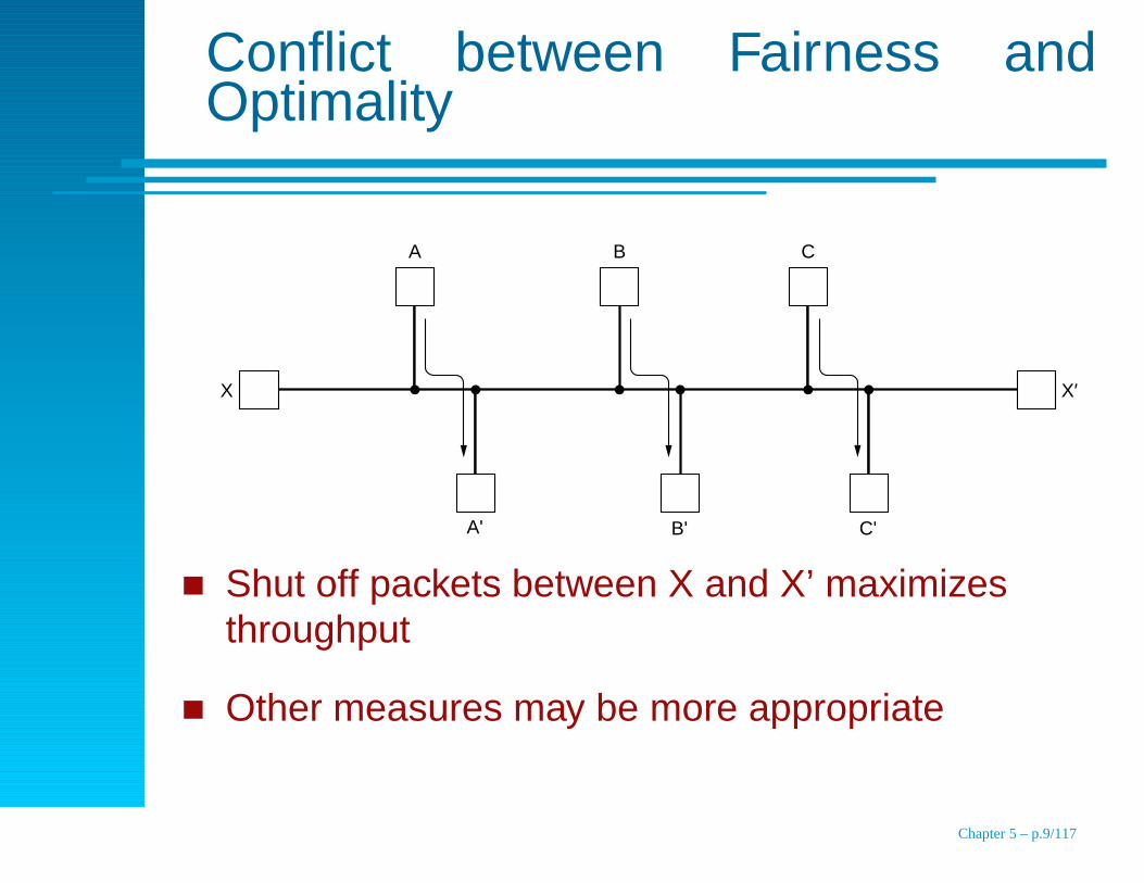
Conflict between Fairness andOptimality
X X′
A B C
A' B' C'
Shut off packets between X and X’ maximizesthroughput
Other measures may be more appropriate
Chapter 5 – p.9/117

Routing AlgorithmsTopics
Optimality PrincipleShortest Path RoutingFloodingDistance Vector RoutingLink State RoutingHierarchical RoutingBroadcast RoutingMulticast RoutingRouting for Mobile HostsRouting in Ad Hoc NetworksNode Lookup in Peer-to-Peer Networks
Chapter 5 – p.10/117
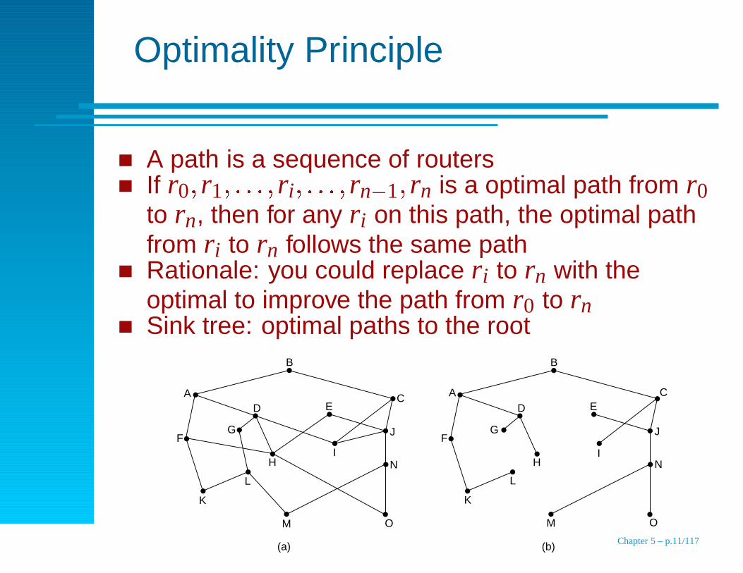
Optimality Principle
A path is a sequence of routersIf r0 � r1 � � � � � ri � � � � � rn � 1 � rn is a optimal path from r0to rn, then for any ri on this path, the optimal pathfrom ri to rn follows the same pathRationale: you could replace ri to rn with theoptimal to improve the path from r0 to rnSink tree: optimal paths to the root
B
A
F
D EC
J
N
O
IH
G
L
M
K
(a)
B
A
F
D EC
J
N
O
IH
G
L
M
K
(b) Chapter 5 – p.11/117
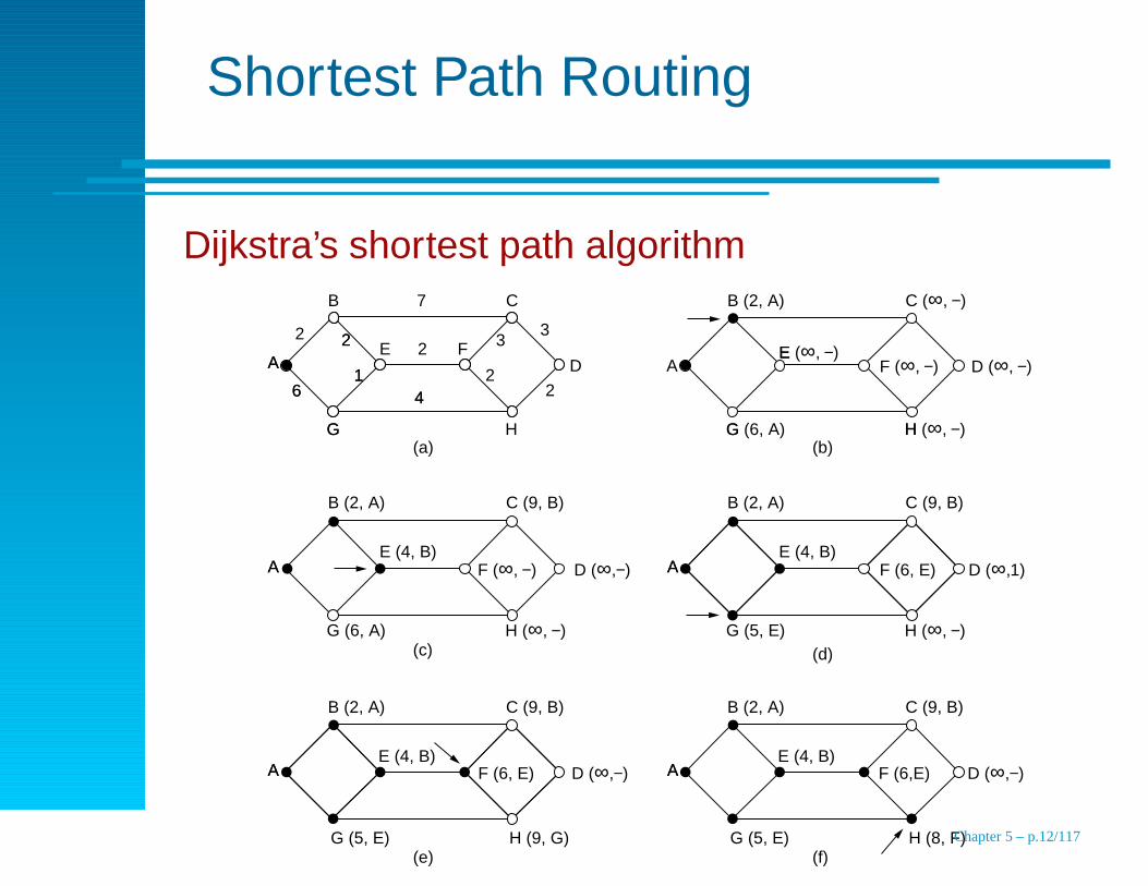
Shortest Path Routing
Dijkstra’s shortest path algorithm
A D1
2
6
G
4
(a)
F (∞, −) D (∞,−)
A
B 7 C
2
H
33
2
2 FE
1
22
6
G
4
A
(c)
A
B (2, A) C (9, B)
H (∞, −)
E (4, B)
G (6, A)
F (6, E) D (∞,−)A
(e)
A
B (2, A) C (9, B)
H (9, G)
E (4, B)
G (5, E)
F (6,E) D (∞,−)A
(f)
A
B (2, A) C (9, B)
H (8, F)
E (4, B)
G (5, E)
F (6, E) D (∞,1)A
(d)
A
B (2, A) C (9, B)
H (∞, −)
E (4, B)
G (5, E)
F (∞, −) D (∞, −)A
H
E
G(b)
B (2, A) C (∞, −)
H (∞, −)
E (∞, −)
G (6, A)
Chapter 5 – p.12/117
Flooding
Duplicate incoming packet on outbound links
Damping
hop count
keep track of messages in the routers
keep track of routers in the messages
Selective flooding: rule out outbound links
Chapter 5 – p.13/117
Distance Vector Routing
Each router maintains a vector of best distances toeach destination
Other names: Bellman-Ford, Ford-Fulkerson, RIP
Update
each router knows “distance to neighbors”
every T sec, the routers exchange their distance vectors
for a neighbor X the distance to i is Xi
�
m where Xi is the
distance repoted by X and m is the distance to X .
Chapter 5 – p.14/117

Distance Vector RoutingExample
(a)
A B C D
E
I J K L
F GH
Router
0122540142318172192429
2436182772031200112233
2031198301960147229
2128362422403119221009
820282017301812100615
AA
IH
II
HH
I−
KK
To A I H K Line
New estimated delay from J
ABCDEFGHIJKL
JA JI JH JKdelay delaydelaydelay
is is is is8 10 12 6
New routing table for J
Vectors received from J's four neighbors
(b)
Chapter 5 – p.15/117
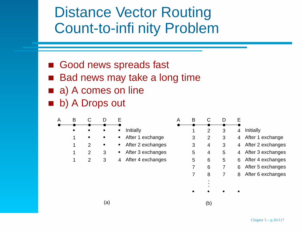
Distance Vector RoutingCount-to-infinity Problem
Good news spreads fastBad news may take a long timea) A comes on lineb) A Drops out
A B C D E
• • • • • • •
• • • 4
1
1
1
1
2
2
2
3
3
InitiallyAfter 1 exchange
After 2 exchanges
After 3 exchanges
After 4 exchanges
A B C D E
1 2 3 4
• • • •
2 3 4
3 4
4
6
3
3
5
5
4
4
6
5
567 6 7
87 8 7
InitiallyAfter 1 exchange
After 2 exchanges
After 3 exchanges
After 4 exchangesAfter 5 exchanges
After 6 exchanges...
(a) (b)
Chapter 5 – p.16/117
Link State Routing
Discover the neighbors and learn their networkaddresses
Measure the delay of cost to each neighbor
Construct a packet describing what you learned
Send this packet to all other routers
Compute the shortest path to every other router
Chapter 5 – p.17/117
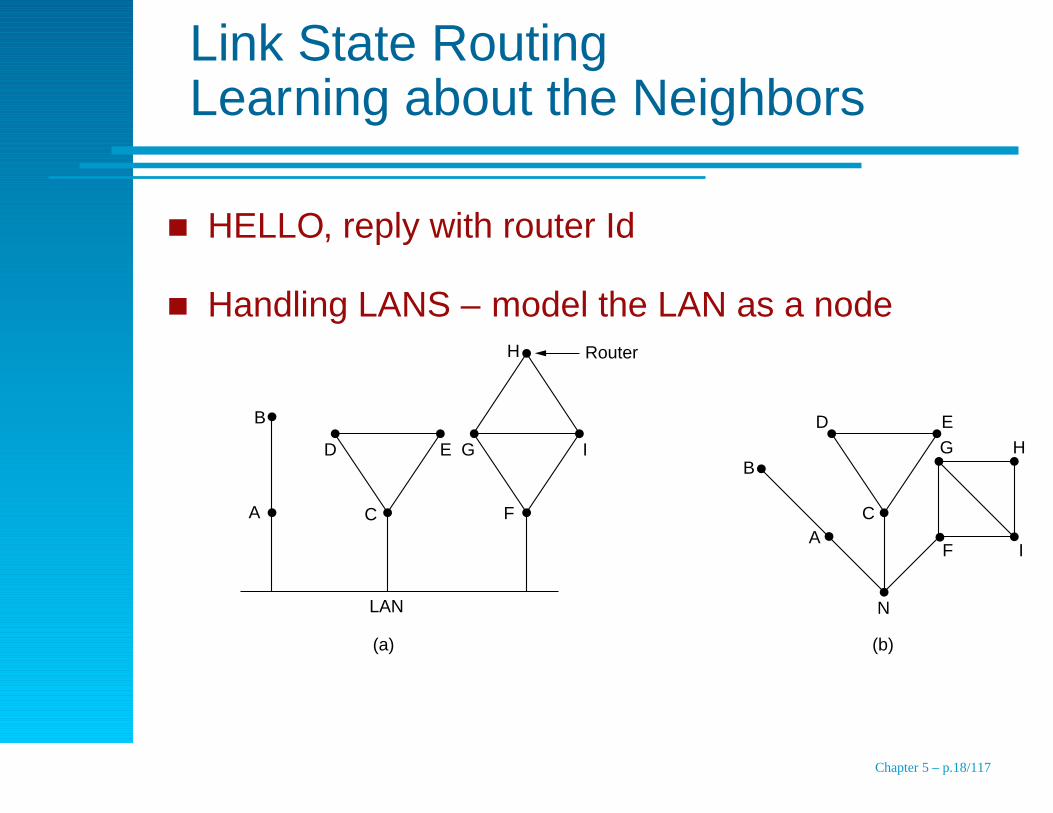
Link State RoutingLearning about the Neighbors
HELLO, reply with router Id
Handling LANS – model the LAN as a nodeRouter
A
B
C
D E
C
D E
H
I
F
G G H
IF
N
A
B
LAN
(a) (b)
Chapter 5 – p.18/117
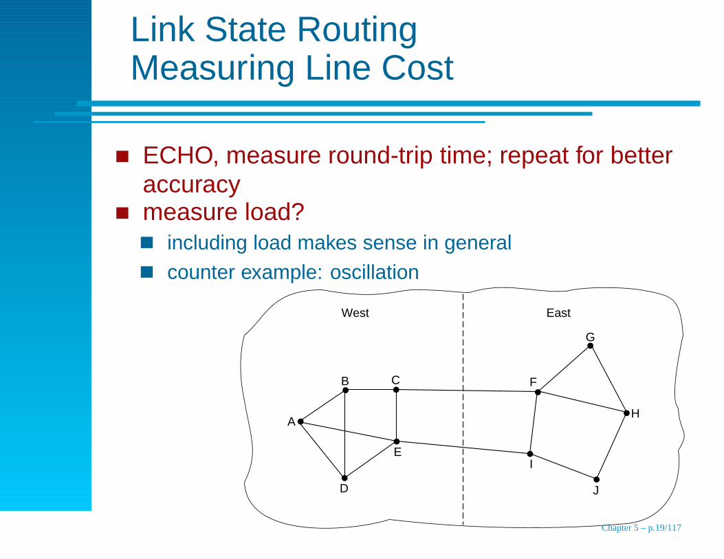
Link State RoutingMeasuring Line Cost
ECHO, measure round-trip time; repeat for betteraccuracymeasure load?
including load makes sense in general
counter example: oscillation
West East
B
A
D
E
C F
G
H
J
I
Chapter 5 – p.19/117
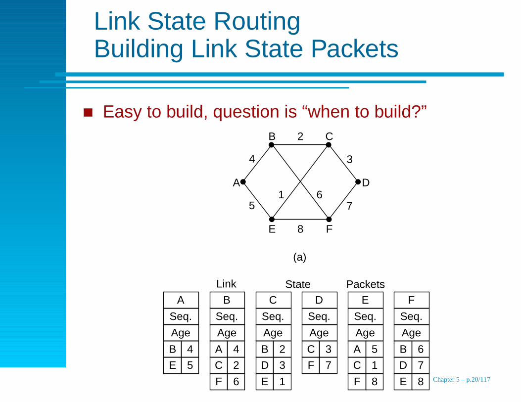
Link State RoutingBuilding Link State Packets
Easy to build, question is “when to build?”B C
E F
A D61
2
8
5 7
4 3
(a)
A
Seq.
Age
B C D E F
B 4
E 5
Seq.
Age
A 4
C 2
Seq.
Age
B 2
D 3
Seq.
Age
C 3
F 7
Seq.
Age
A 5
C 1
Seq.
Age
B 6
D 7
F 6 E 1 F 8 E 8
Link State Packets
(b)
Chapter 5 – p.20/117
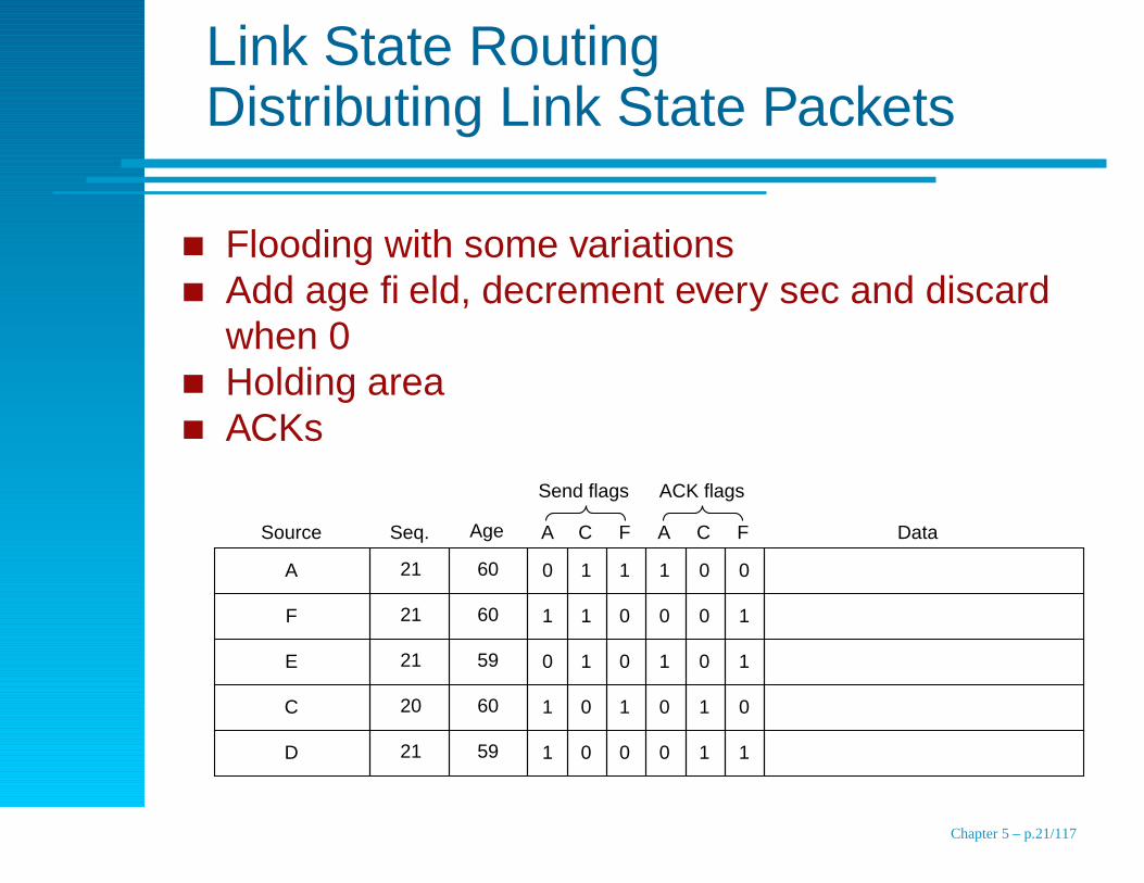
Link State RoutingDistributing Link State Packets
Flooding with some variationsAdd age field, decrement every sec and discardwhen 0Holding areaACKs
D 21 59 1 0 0 0 1 1
C 20 60 1 0 1 0 1 0
E 21 59 0 1 0 1 0 1
F 21 60 1 1 0 0 0 1
A 21 60 0 1 1 1 0 0
Source Seq. Age A C F A C F Data
Send flags ACK flags
Chapter 5 – p.21/117
Link State RoutingComputing the Routes
Reconstruct entire graph
Two values for each link (one in each direction)
Run Dijkstra’s shortest path locally
Chapter 5 – p.22/117
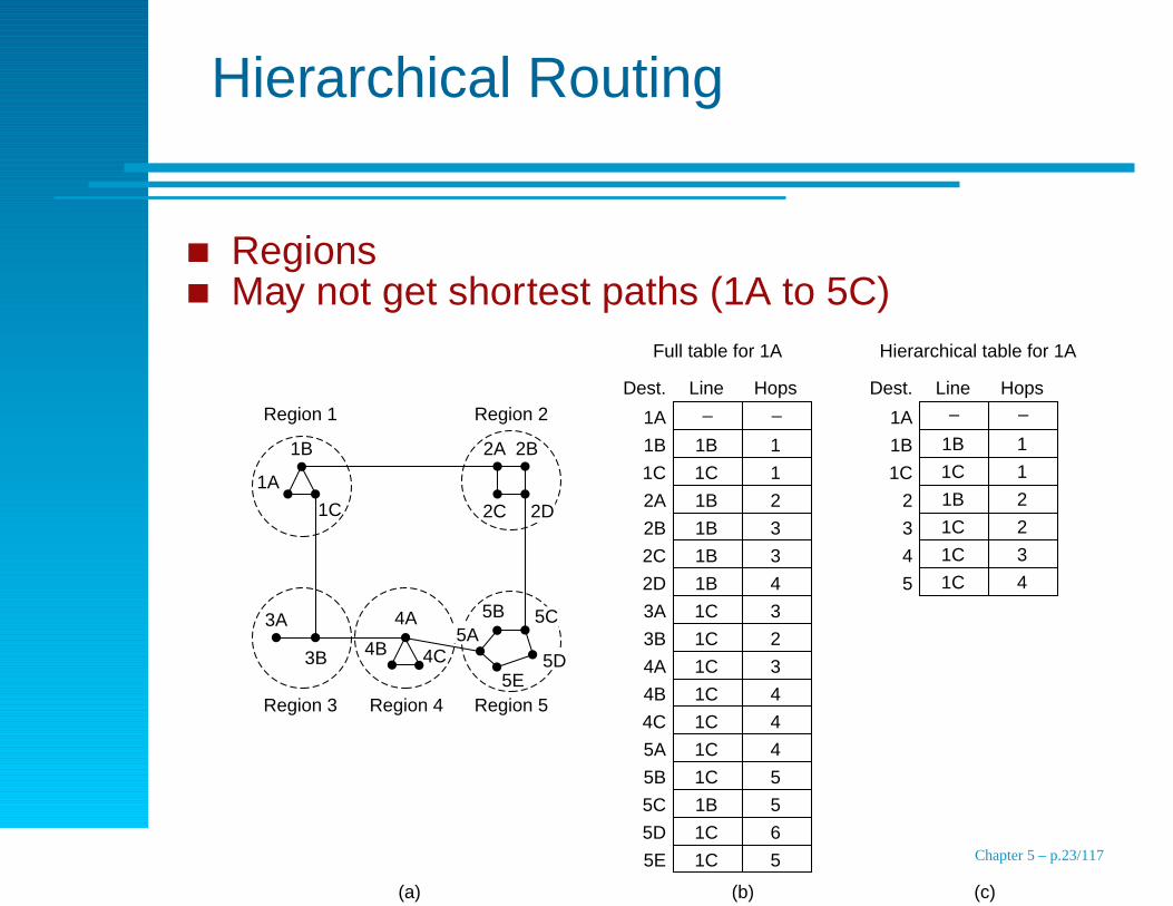
Hierarchical Routing
RegionsMay not get shortest paths (1A to 5C)
Region 1 Region 2
Region 3 Region 5Region 4
1B
1A
1C
2A 2B
2C
5B 5C5A
5E5D
2D
4A
4B 4C
3A
3B
1B 1
1C 1
1B 2
1B 3
1B 3
1B 4
1C 3
1C 2
1C 3
1C 4
1C 4
1C 4
1C 5
1B 5
1C 6
1C 5
– –1A
1C
2A
2B
2C
2D
3A
3B
4A
4B
4C
5A
5B
5C
5D
5E
1B
Line HopsDest.
Full table for 1A
1A
1C
2
3
4
5
1B
Line HopsDest.
Hierarchical table for 1A
1B 1
1C 1
1B 2
1C 2
1C 3
1C 4
– –
(a) (b) (c)
Chapter 5 – p.23/117
Broadcast Routing
Multicast (send to each destination)
Flooding
Multidestination routing (list of addresses)
Spanning tree (need to construct the tree)
Reverse path forwarding
mimic spanning tree without set-up step
forward packets that arrive on the best path from the source
discard packets arriving on non optimal paths from the
source
Chapter 5 – p.24/117
Broadcast RoutingReverse Path Forwarding
I
F H J N
A D GKE O M O
GC D N
BH L
L B
A
E
H
B CD
F
J
G
O
MK
LN
I
(a)
AB C
D
G
J
O
FI
E
H
K
L
M
N
(b) (c)
KE
H
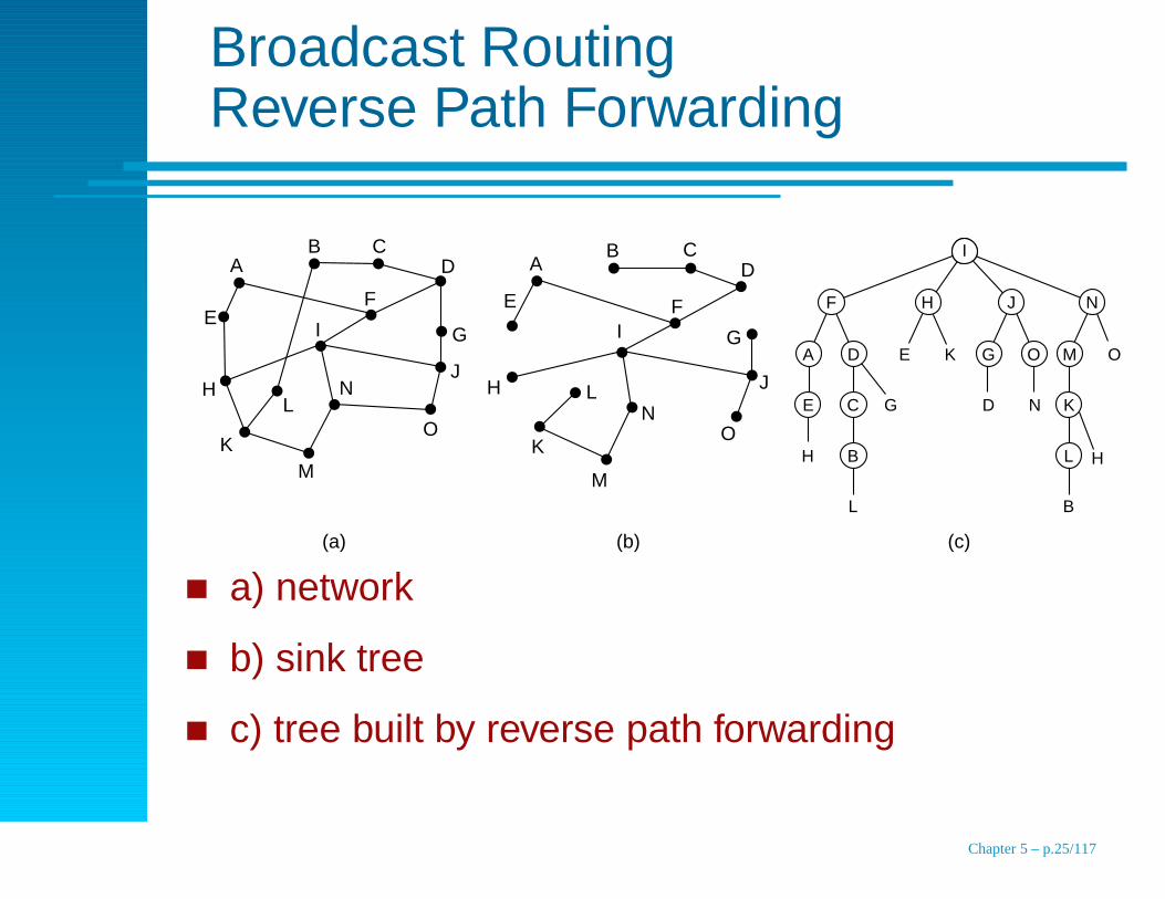
a) network
b) sink tree
c) tree built by reverse path forwarding
Chapter 5 – p.25/117
Multicast Routing
Group management (join, leave, create and destroy)
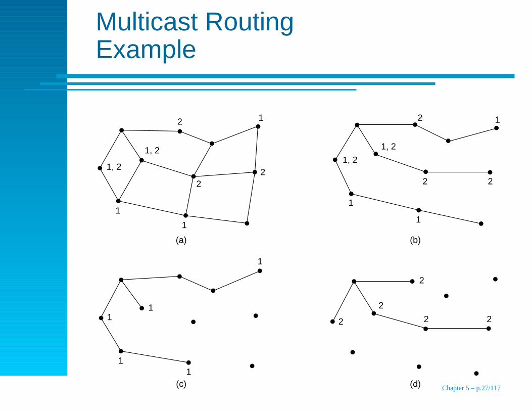
Spanning trees
Built by routers with complete information
PRUNE messages (don’t send me more messages for this
group) – scalability
Core-based trees, send messages to core node which
relays to the group
Chapter 5 – p.26/117
Multicast RoutingExample
1, 2
1
1, 2
2 1 12
2
1
2
1, 2
1, 2
2 2
1
1
11
11
1
2
2
2
2 2
(a) (b)
(c) (d) Chapter 5 – p.27/117
Routing for Mobile HostsExample Environment
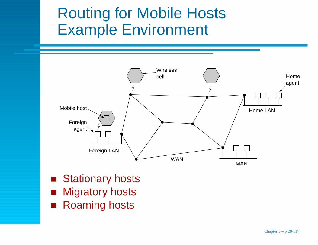
Foreign agent
Foreign LAN
WANMAN
Home LAN
Home agent
Mobile host
Wireless cell
Stationary hostsMigratory hostsRoaming hosts
Chapter 5 – p.28/117
Mobile Hosts
Home locationHome agent, Foreign agent
Registration on a remote networkmobile host finds foreign agent (wait or ask)
register with foreign agent: home address, current data link
address, security information
foreign agent contacts home agent: security information is
used to authenticate the mobile host
home agent inspects security information and ACKs
foreign agent makes an entry in its table
Chapter 5 – p.29/117
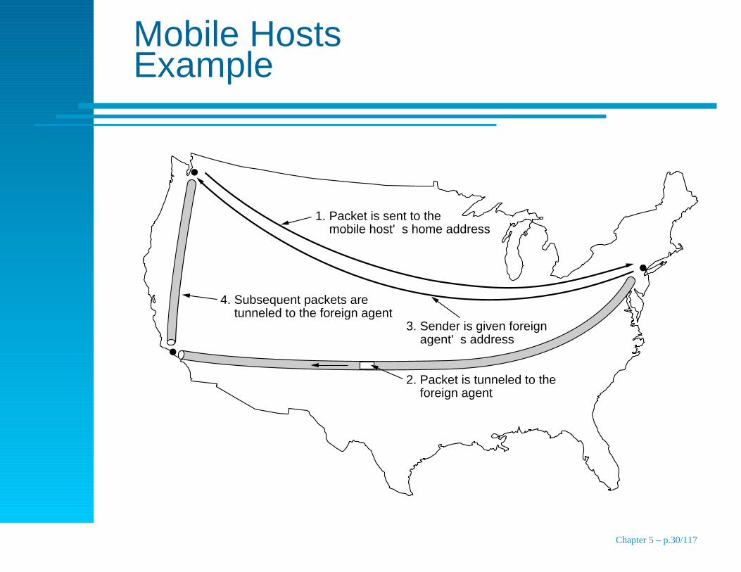
Mobile HostsExample
1. Packet is sent to the mobile host's home address
2. Packet is tunneled to the foreign agent
3. Sender is given foreign agent's address
4. Subsequent packets are tunneled to the foreign agent
Chapter 5 – p.30/117
Ad Hoc NetworksRoute Discovery
Routers are mobile
Examples
military battlefield
fleet of ships at sea
emergency workers at an earthquake
a gathering of nerds with notebook computers and no
802.11 infrastructure
Chapter 5 – p.31/117

Ad Hoc NetworksRoute Discovery
On demand route generation
CBA
D
E
G
IH
F
(a)
CBA
D
E
G
IH
F
(b)
Range of A's broadcast
CBA
D
E
G
IH
F
(c)
CBA
D
E
G
IH
F
(d)
Chapter 5 – p.32/117
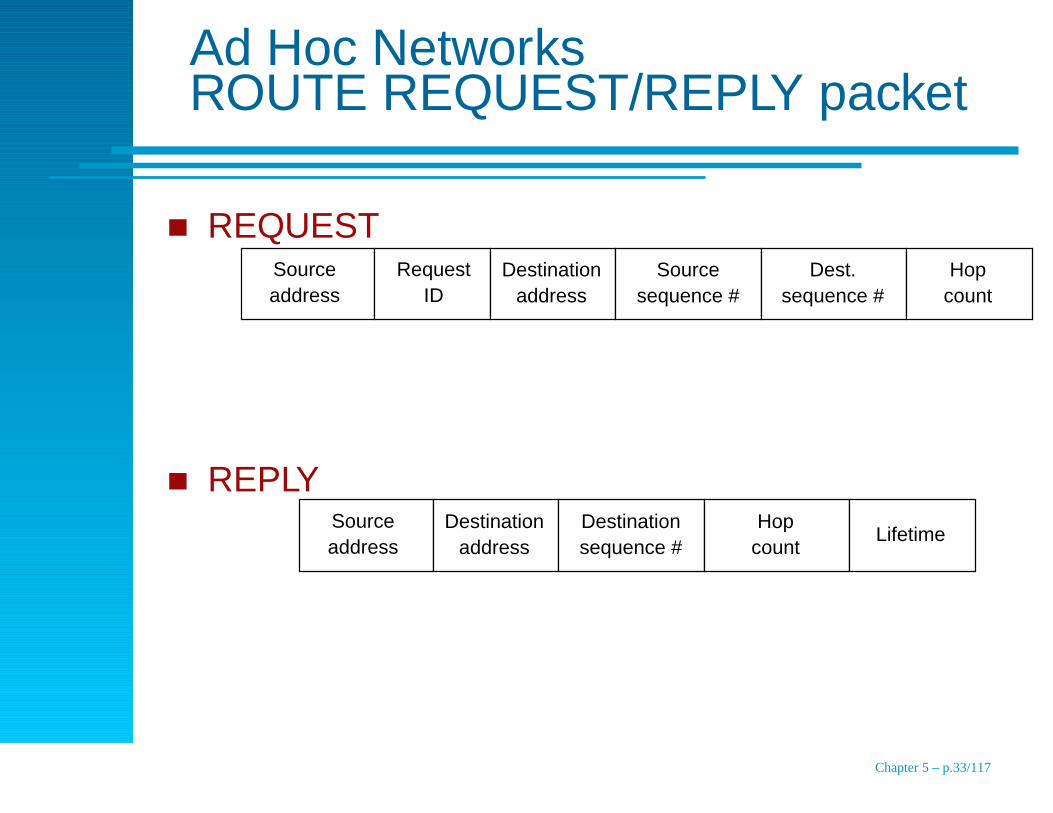
Ad Hoc NetworksROUTE REQUEST/REPLY packet
REQUESTSource address
Request ID
Destination address
Source sequence #
Dest. sequence #
Hop count
REPLYSource address
Destination address
Destination sequence #
Hop count
Lifetime
Chapter 5 – p.33/117

Ad Hoc NetworksRoute Maintenance
CBA
D
E
IH
F
(b)(a)
A
Dest.
A
Next hop
1
Distance
F, G
Active neighbors
B B 1 F, G
C B 2 F
E G 2
F F 1 A, B
G G 1 A, B
H F 2 A, B
I G 2 A, B
Other fields
Chapter 5 – p.34/117

Peer-to-Peer Networks
0
16
2,3
4
4 4
3
2
2,3
0,1
0,1
0,1
31 1
17 15
230
1418
29 3
19 13
428
1220
27
26
25
24 8
7
23 9
6
22 10
5
21 11
2 4
3 4 Node 1's finger table
5 7
9 12
17 20
Start
IP a
ddr
o
f suc
cess
or
5 7
6 7 Node 4's finger table
8 12
12 12
20 20
Start
IP a
ddr
o
f suc
cess
or
13 15
14 15 Node 12's finger table
16 20
20 20
28 1
Start
IP a
ddr
o
f suc
cess
or
(b)(a)
Node identifier
Actual node
Chapter 5 – p.35/117

Topics
End-to-end transmission, routing
Design Issues
Routing Algorithms
Congestion Control Algorithms
Quality of Service
Internetworking
The Network Layer in the Internet
Chapter 5 – p.36/117
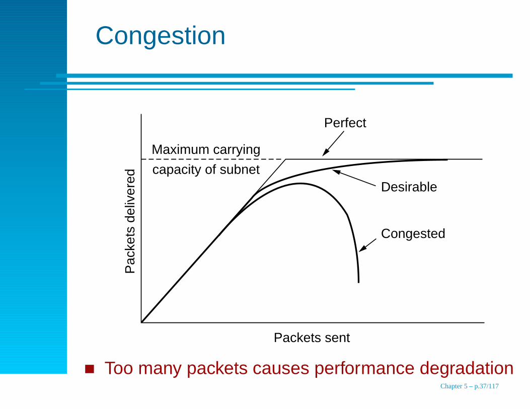
Congestion
Maximum carrying
capacity of subnet
Pac
kets
del
iver
edPerfect
Desirable
Congested
Packets sent
Too many packets causes performance degradationChapter 5 – p.37/117

CongestionCauses
Inadequate memory for outgoing flows
Nagle (1997), unbounded router memory make the
problem worse (retransmissions)
Slow processors
Slow outbound lines
Chapter 5 – p.38/117
CongestionIssues
Solutions
increase capacity
decrease load
Congestion control versus flow control
Congestion control is global to the network – emergent
Flow control is point-to-point
Chapter 5 – p.39/117

CongestionControl Principles, Open Loop
“Design it right”
decide when to accept new traffic
decide when and which packets to discard
scheduling
Chapter 5 – p.40/117
CongestionControl Principles, Closed Loop
monitor and determine where congestion occurspercentage of packets discardedqueue lengths
number of packets retransmitted due to timeout
average and standard deviation in packet delaypass information to places where action can betaken
notify traffic source
use a bit field on outgoing packets to notify neighbors
send probe packetsadjust system operation to correct the problem
route around congestion
reactivity is an issueChapter 5 – p.41/117

Congestion Prevention Policies
Layer Policies
Transport Retransmission policyOut-of-order caching policyAcknowledgement policyFlow control policyTimeout determination
Network Virtual circuits versus datagram inside the subnetPacket queueing and service policyPacket discard policyRouting algorithmPacket lifetime management
Data link Retransmission policyOut-of-order caching policyAcknowledgement policyFlow control policy
Chapter 5 – p.42/117
Congestion ControlVirtual-Circuits
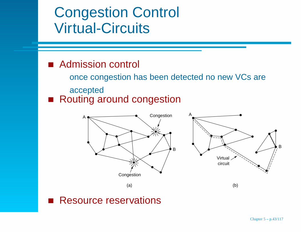
Admission controlonce congestion has been detected no new VCs are
acceptedRouting around congestion
A
Congestion
Virtual circuit
Congestion
B
A
B
(a) (b)
Resource reservations
Chapter 5 – p.43/117
Congestion ControlDatagram
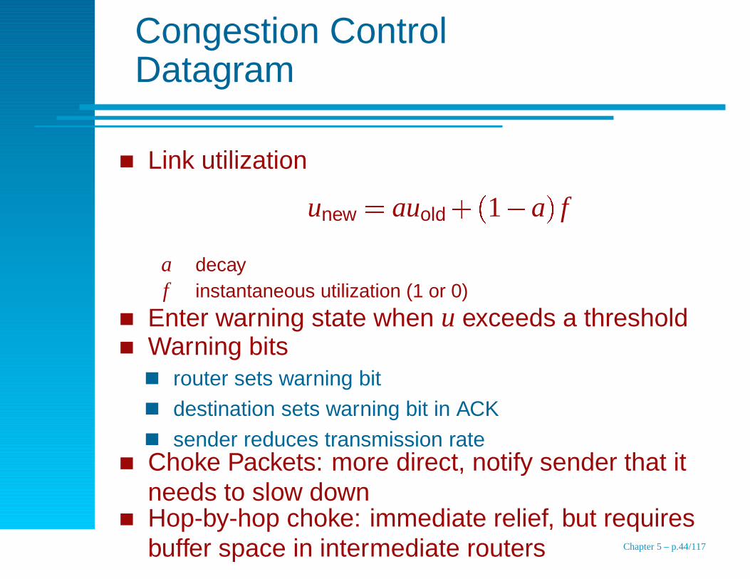
Link utilization
unew
� auold
�
1 � a�
f
a decayf instantaneous utilization (1 or 0)
Enter warning state when u exceeds a thresholdWarning bits
router sets warning bitdestination sets warning bit in ACK
sender reduces transmission rateChoke Packets: more direct, notify sender that itneeds to slow downHop-by-hop choke: immediate relief, but requiresbuffer space in intermediate routers Chapter 5 – p.44/117

Congestion ControlChoke versus Hop-by-hop
(a) (b)
Choke
Choke
B C
A D
E F
ChokeReduced
flow
Flow is still at maximum rate
Flow is reduced
B C
A D
E FHeavy flow
Choke
Choke
Choke
Reduced flow
Chapter 5 – p.45/117

Load Shedding
Heavy artilleryWhich packets?
wine – older is better, drop newer packets
file transfer, avoid intermediate transmissions
milk – newer is better, drop older packets
video streams, old frames are useless
needs application informationapps need incentive to request lower levels of service
Random Early Detection (RED) (Floyd andJacobson, 1993)
lost packets mean congestion
router monitors queues, drops random packets
Chapter 5 – p.46/117
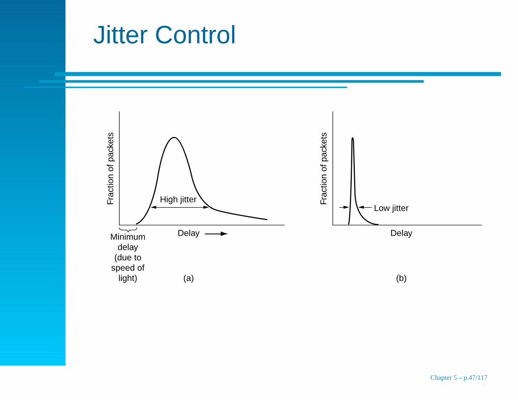
Jitter Control
High jitterLow jitter
Minimum delay
(due to speed of
light)
Delay
(a)
Frac
tion
of p
acke
ts
Frac
tion
of p
acke
ts
Delay
(b)
Chapter 5 – p.47/117

Topics
End-to-end transmission, routing
Design Issues
Routing Algorithms
Congestion Control Algorithms
Quality of Service
Internetworking
The Network Layer in the Internet
Chapter 5 – p.48/117
Quality of Service
Requirements
Techniques
Integrated Services
Differentiated Services
Label Switching and MPLS
Chapter 5 – p.49/117

Quality of Service Requirements
Application Reliability Delay Jitter Bandwidth
E-mail High Low Low Low
File transfer High Low Low Medium
Web access High Medium Low Medium
Remote login High Medium Medium Low
Audio on demand Low Low High Medium
Video on demand Low Low High High
Telephony Low High High Low
Videoconferencing Low High High High
Chapter 5 – p.50/117
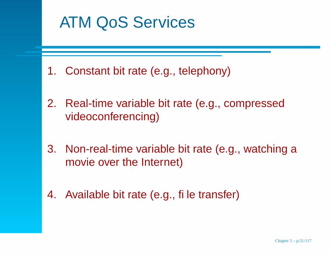
ATM QoS Services
1. Constant bit rate (e.g., telephony)
2. Real-time variable bit rate (e.g., compressedvideoconferencing)
3. Non-real-time variable bit rate (e.g., watching amovie over the Internet)
4. Available bit rate (e.g., file transfer)
Chapter 5 – p.51/117

QoS TechniquesOverprovisioning
Provide more capacity (buffers, bandwidth, etc) thanyou could need
Typical of real-times systems, estimate how muchyou need and add 30%
Expensive
you may get better at estimating how much is needed
but you purchased the expensive version of the router
Telephone company
Chapter 5 – p.52/117
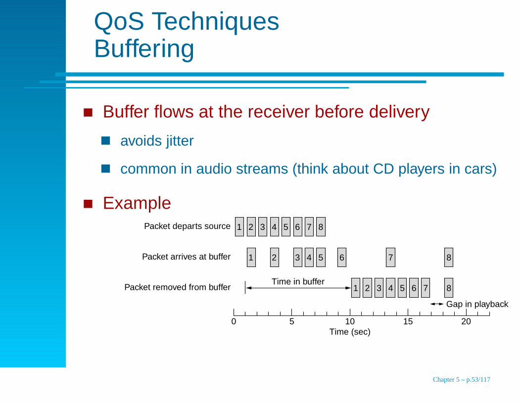
QoS TechniquesBuffering
Buffer flows at the receiver before delivery
avoids jitter
common in audio streams (think about CD players in cars)
Example
0 5
1 2 3 4 5 6 7 8
10Time (sec)
Time in buffer
15 20
Gap in playback
Packet removed from buffer
1 2 3 4 5 6 7 8Packet arrives at buffer
1 2 3 4 5 6 7 8Packet departs source
Chapter 5 – p.53/117

QoS TechniquesTraffic Shaping
Deal with the problem at the sender, rather than thereceiverHere’s my outgoing traffic pattern, can you handleit?
service level agreement
traffic policing
Sliding window protocols introduce burstytransmissionTechniques
leaky bucket
token bucket
Chapter 5 – p.54/117
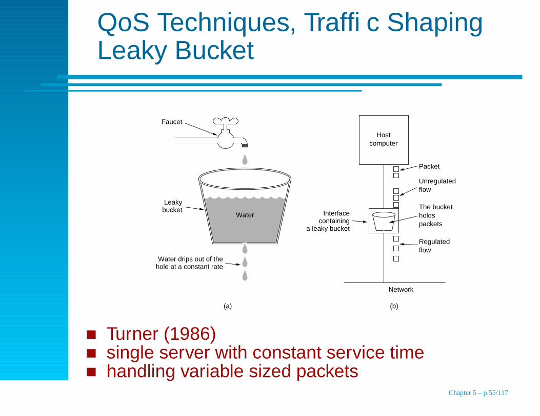
QoS Techniques, Traffic ShapingLeaky Bucket
Faucet
Leaky bucket
Water drips out of the hole at a constant rate
Host computer
Packet
The bucket holds packets
Unregulated flow
Regulated flow
Network
Interface containing
a leaky bucket
Water
(b)(a)
Turner (1986)single server with constant service timehandling variable sized packets
Chapter 5 – p.55/117

QoS Techniques, Traffic ShapingLeaky Bucket Example
(a)
Time (msec)0 500
0 500
(b)
Time (msec)
25 MB/sec for 40 msec
2 MB/sec for 500 msec
a) Offered loadb) Resulting load
Chapter 5 – p.56/117
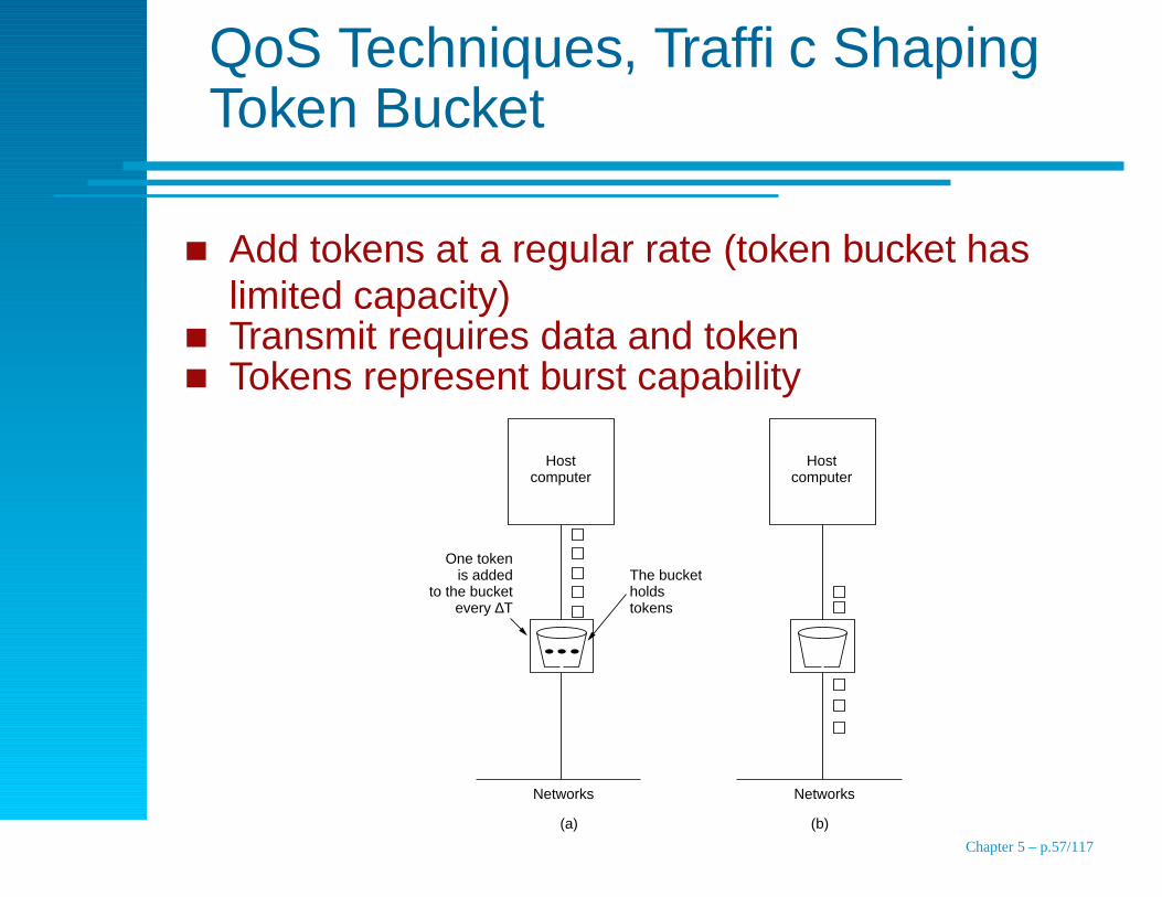
QoS Techniques, Traffic ShapingToken Bucket
Add tokens at a regular rate (token bucket haslimited capacity)Transmit requires data and tokenTokens represent burst capability
Host computer
Networks
Host computer
The bucket holds tokens
Networks
One token is added
to the bucket every ∆T
(a) (b)
Chapter 5 – p.57/117
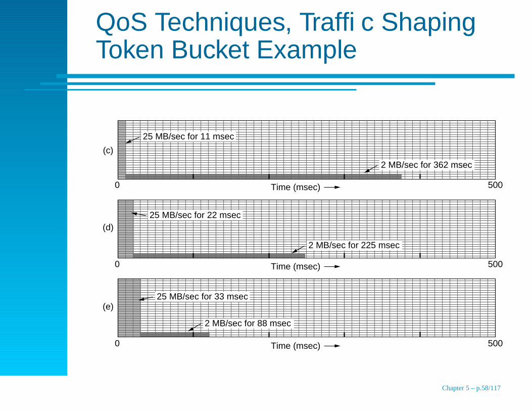
QoS Techniques, Traffic ShapingToken Bucket Example
0 500
0 500
0 500
(c)
(d)
(e)
Time (msec)
Time (msec)
Time (msec)
25 MB/sec for 11 msec
25 MB/sec for 22 msec
25 MB/sec for 33 msec
2 MB/sec for 88 msec
2 MB/sec for 225 msec
2 MB/sec for 362 msec
Chapter 5 – p.58/117

QoS Techniques, Traffic ShapingToken Bucket feeding Leaky Bucket
0 500
(f)
Time (msec)
2 MB/sec for 190 msec
10 MB/sec for 62 msec
Chapter 5 – p.59/117
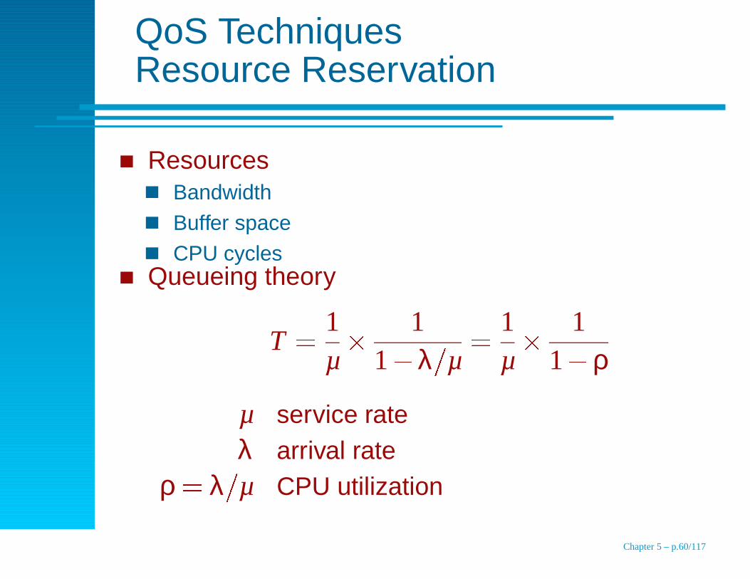
QoS TechniquesResource Reservation
ResourcesBandwidth
Buffer space
CPU cyclesQueueing theory
T � 1µ
� 11 � λ
�
µ
� 1µ
� 11 � ρ
µ service rateλ arrival rate
ρ � λ�
µ CPU utilization
Chapter 5 – p.60/117
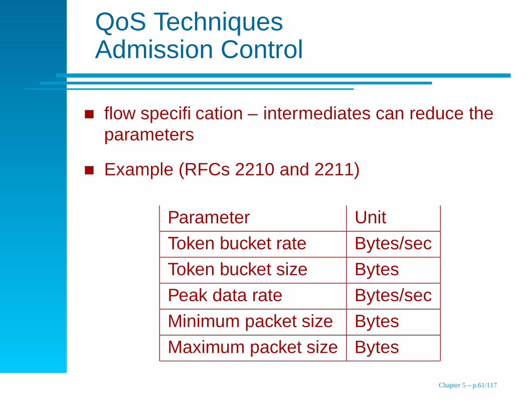
QoS TechniquesAdmission Control
flow specification – intermediates can reduce theparameters
Example (RFCs 2210 and 2211)
Parameter Unit
Token bucket rate Bytes/sec
Token bucket size Bytes
Peak data rate Bytes/sec
Minimum packet size Bytes
Maximum packet size Bytes
Chapter 5 – p.61/117
QoS TechniquesProportional Routing
Most routers use “best path” routing
Could also divide traffic to a destination overmultiple outbound legs equally or in proportion tobandwidth
Chapter 5 – p.62/117

QoS TechniquesPacket Scheduling
Fair queueinga queue per flow per output portqueues are serviced in round robin fashion
higher bandwidth to flows that use large packetsDemers et al. (1990)
simulate byte-by-byte round robin
sort in reverse finishing order
example
O
(a) (b)
1A 6 11 15 19 20
2B 7 12 16
3C 8
4D 9 13 17
5
C
Packet
B
D
E
A
8
Finishing time
16
17
18
20E 10 14 18
Weighted fair queueing Chapter 5 – p.63/117
Integrated Services
Streaming multimedia
RFCs 2205-2210
Flow based algorithms or integrated services
Unicast and multicast services
unicast, e.g., streaming video from new service
multicast, e.g., digital TV broadcast
Chapter 5 – p.64/117
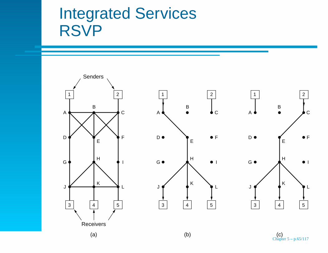
Integrated ServicesRSVP
A
D
G
J
C
F
I
L
B
K
H
E
1 2
3 4 5
Receivers
Senders
A
D
G
J
C
F
I
L
B
K
H
E
1 2
3 4 5
1 2
3 4 5
A
D
G
J
C
F
I
L
B
K
H
E
(a) (b) (c)Chapter 5 – p.65/117

Integrated ServicesRSVP
A
D
G
J
C
F
Bandwidth reserved for source 1
Bandwidth reserved for source 2
I
L
B
K
H
E
1 2
3 4 5
A
D
G
J
C
F
I
L
B
K
H
E
1 2 2
3 4 5
A
D
G
J
C
F
I
L
B
K
H
E
(b) (c)(a)
3 4 5
1
Chapter 5 – p.66/117
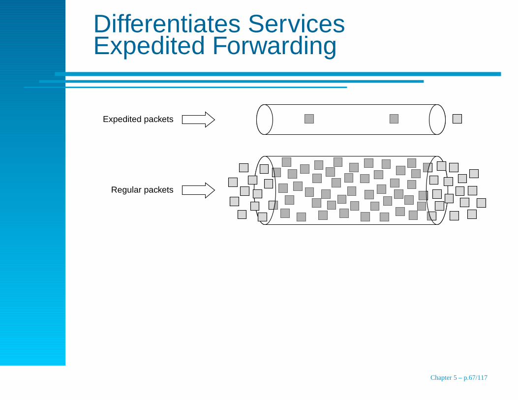
Differentiates ServicesExpedited Forwarding
Regular packets
Expedited packets
Chapter 5 – p.67/117
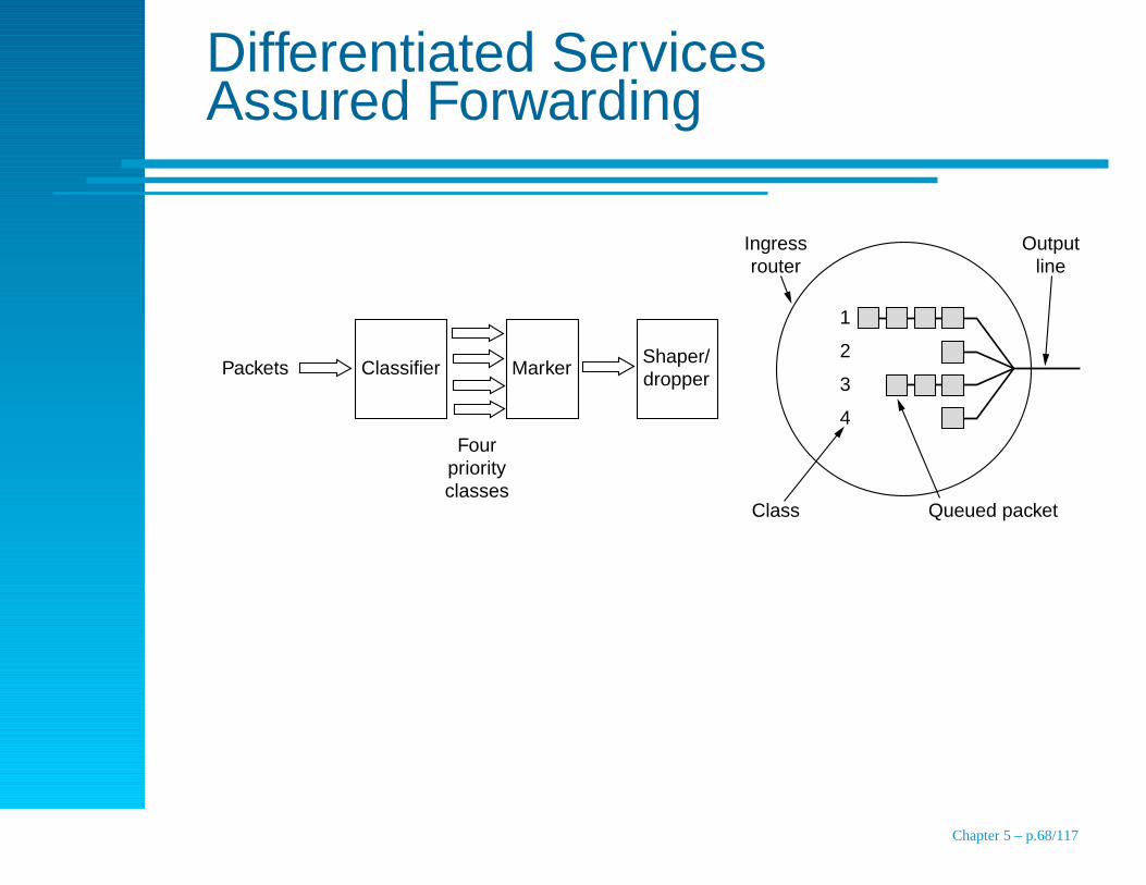
Differentiated ServicesAssured Forwarding
Packets Classifier Marker
Four priority classes
Shaper/ dropper
Output line
Ingress router
Class Queued packet
1
2
3
4
Chapter 5 – p.68/117
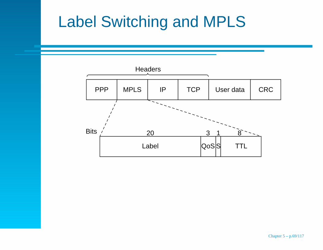
Label Switching and MPLS
PPP MPLS IP
Label QoS S TTL
20Bits
Headers
3 1 8
TCP User data CRC
Chapter 5 – p.69/117
Topics
End-to-end transmission, routing
Design Issues
Routing Algorithms
Congestion Control Algorithms
Quality of Service
Internetworking
The Network Layer in the Internet
Chapter 5 – p.70/117
Internetworking
Network Differences
Connecting Networks
Concatenated Virtual Circuits
Connectionless Internetworking
Tunneling
Internetwork Routing
Fragmentation
Chapter 5 – p.71/117
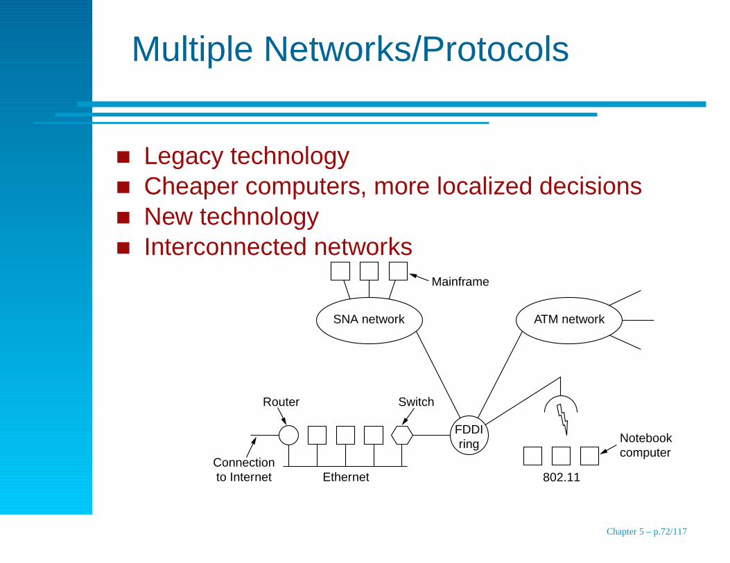
Multiple Networks/Protocols
Legacy technologyCheaper computers, more localized decisionsNew technologyInterconnected networks
Ethernet
Connection to Internet
Switch
Mainframe
Router
802.11
Notebook computer
FDDI ring
SNA network ATM network
Chapter 5 – p.72/117

Network Differences
Item Some possibilities
Service offered Connection oriented versus connectionless
Protocols IP, IPX, SNA, ATM, MPLS, AppleTalk, etc.
Addressing Flat (802) versus Hierarchical (IP)
Multicasting Present or absent (also broadcasting)
Packet size Every network has its own maximum
Quality of service Present or absent; many different kinds
Error handling Reliable, ordered, and unordered delivery
Flow control Sliding window, rate control =, other, or none
Congestion control Leaky bucket, token bucket, RED, choke packets, etc.
Security Privacy rules, encryption, etc.
Parameters Different timeouts, flow specifications, etc.
Accounting By connect time, by packet, by byte, or not at all
Chapter 5 – p.73/117
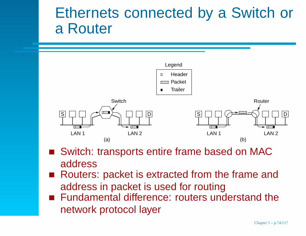
Ethernets connected by a Switch ora Router
LAN 1
Legend
Packet
Header
Trailer
LAN 2(b)
RouterSwitch
S D
LAN 1 LAN 2(a)
S D
Switch: transports entire frame based on MACaddressRouters: packet is extracted from the frame andaddress in packet is used for routingFundamental difference: routers understand thenetwork protocol layer
Chapter 5 – p.74/117
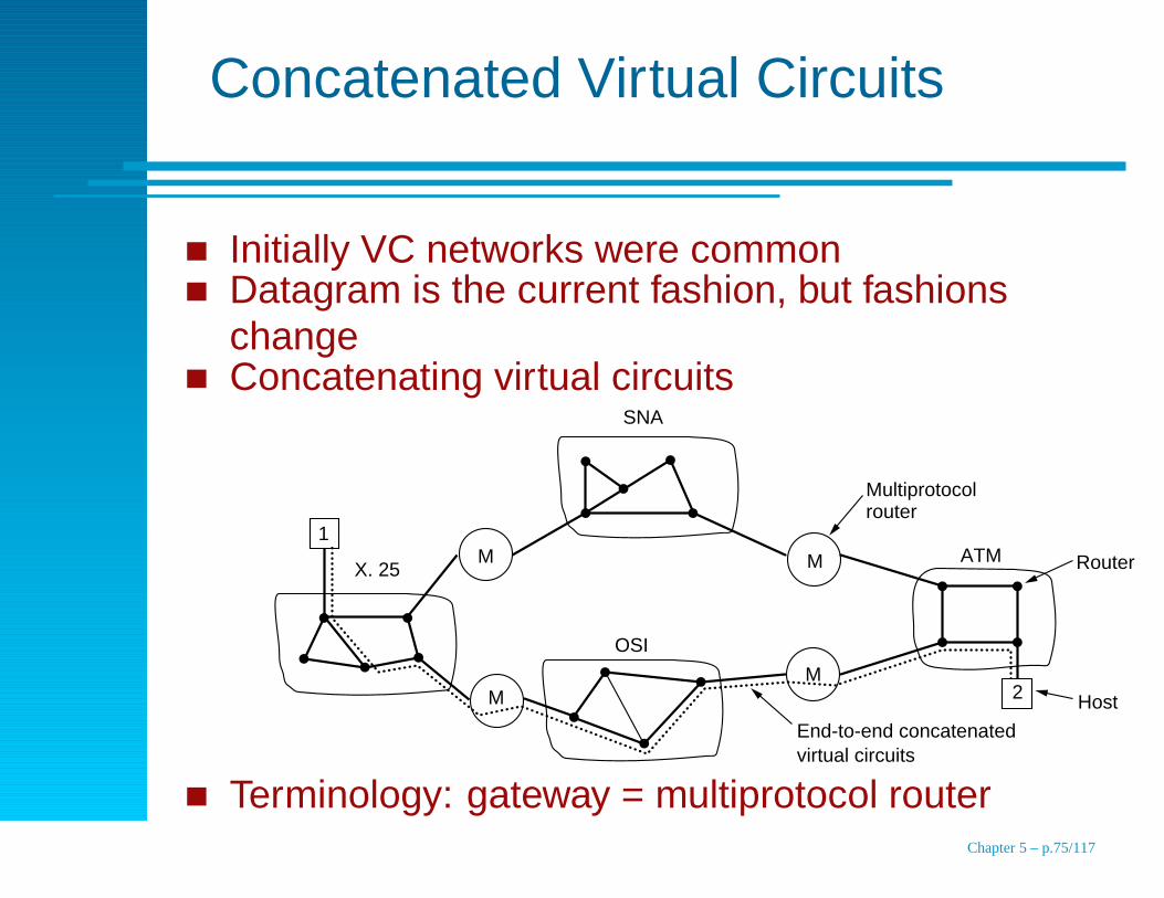
Concatenated Virtual Circuits
Initially VC networks were commonDatagram is the current fashion, but fashionschangeConcatenating virtual circuits
X. 25
M
M
OSI
M
M ATM
End-to-end concatenated virtual circuits
Router
Host
Multiprotocol router
SNA
1
2
Terminology: gateway = multiprotocol routerChapter 5 – p.75/117
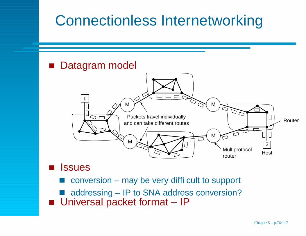
Connectionless Internetworking
Datagram model
M
M
M
M
2
Host
Router
1
Packets travel individually and can take different routes
Multiprotocol router
Issuesconversion – may be very difficult to supportaddressing – IP to SNA address conversion?
Universal packet format – IP
Chapter 5 – p.76/117

Comparison
Concatenated virtual circuitsAdvantages (same as VCs in a subnet)
reserved buffers
guaranteed sequencing
short headers
avoid problems due to delayed or duplicated packetsDisadvantages
table space required when connections are idle
not alternate routing for congestion or failure
difficult when a subnet is unreliable datagramDatagram
potential for congestion, ability to adapt congestion
can easily mix connection oriented and datagram subnetsChapter 5 – p.77/117
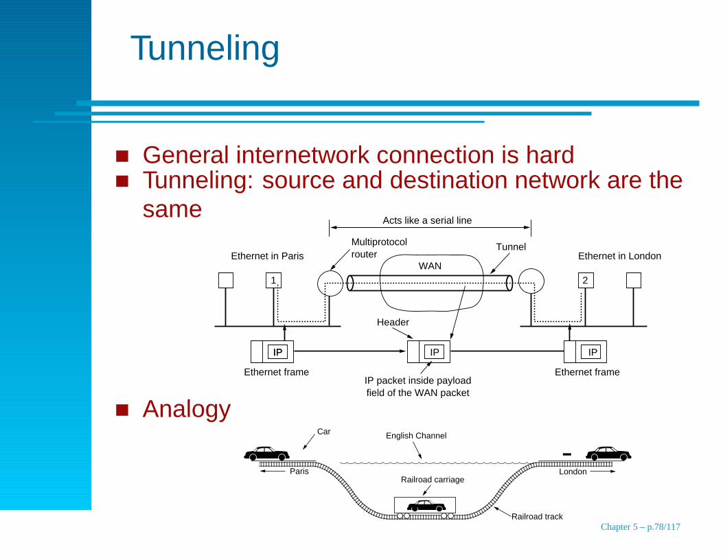
Tunneling
General internetwork connection is hardTunneling: source and destination network are thesame
IPIP IPIP
1 2
Acts like a serial line
WAN
Multiprotocol routerEthernet in Paris
Ethernet frame Ethernet frame
Header
TunnelEthernet in London
IP packet inside payload field of the WAN packet
AnalogyCar English Channel
Paris London
Railroad track
Railroad carriage
Chapter 5 – p.78/117
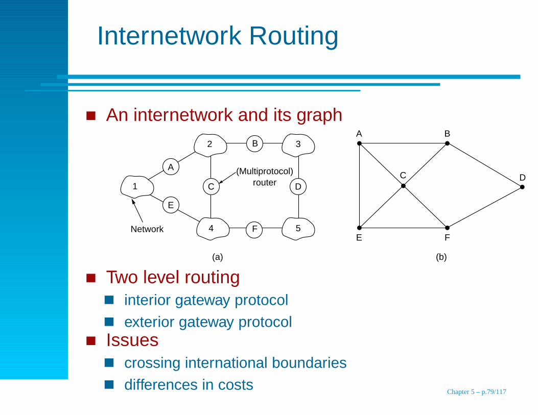
Internetwork Routing
An internetwork and its graph
1
2 3
54
(Multiprotocol) router
Network
A B
E F
C D
(a) (b)
A
B
E
DC
F
Two level routinginterior gateway protocol
exterior gateway protocolIssues
crossing international boundaries
differences in costsChapter 5 – p.79/117
FragmentationReasons
Hardware (e.g., the size of an Ethernet frame).
Operating systems (e.g., all buffers are 512 bytes).
Protocols (e.g., the number of bits in the packetlength field).
Compliance with some (inter)national standard.
Desire to reduce error-induced retransmissions tosome level.
Desire to prevent one packet from occupying thechannel too long.
Chapter 5 – p.80/117
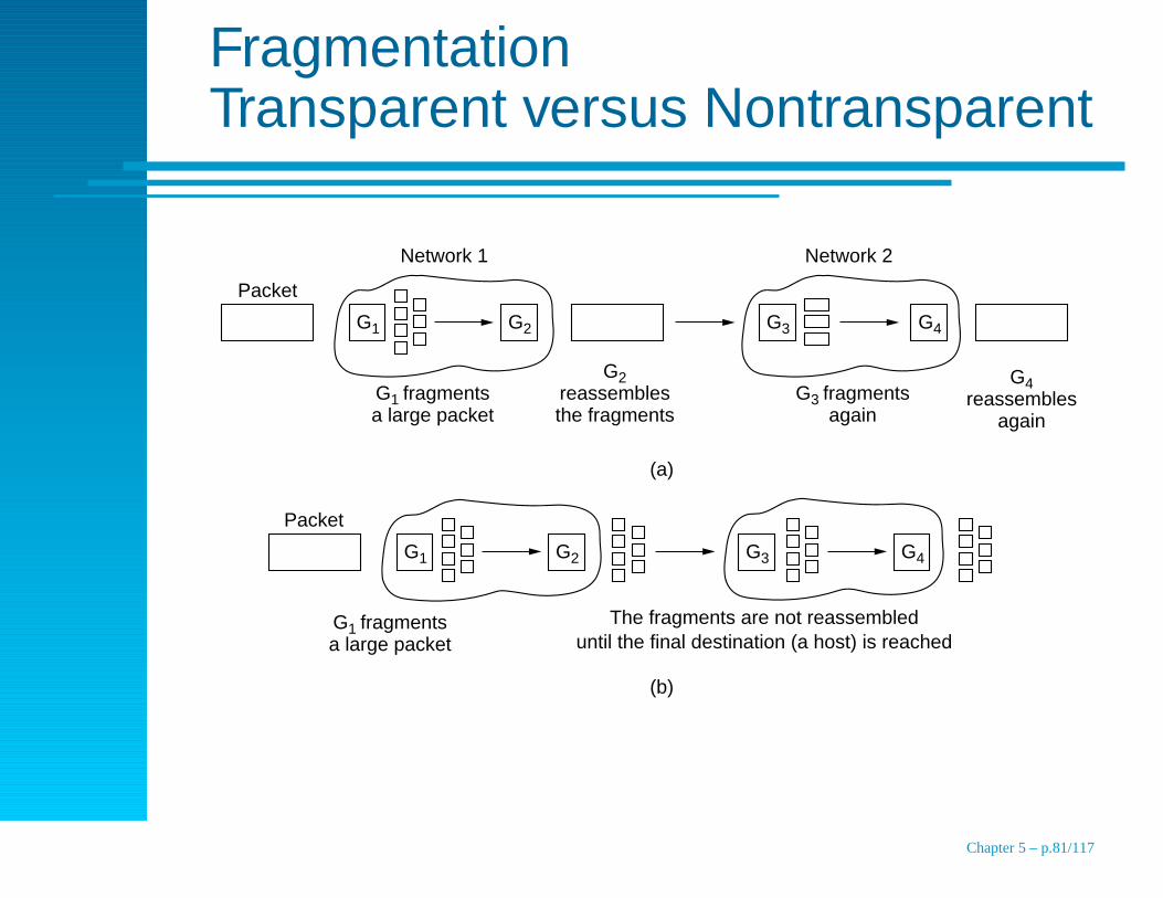
FragmentationTransparent versus Nontransparent
G1 G2 G3 G4
G1 G2 G3 G4
Packet
Network 1
G1 fragments a large packet
G2 reassembles the fragments
G3 fragments
again
G4 reassembles
again
Network 2
(a)
Packet
G1 fragments a large packet
The fragments are not reassembled until the final destination (a host) is reached
(b)
Chapter 5 – p.81/117
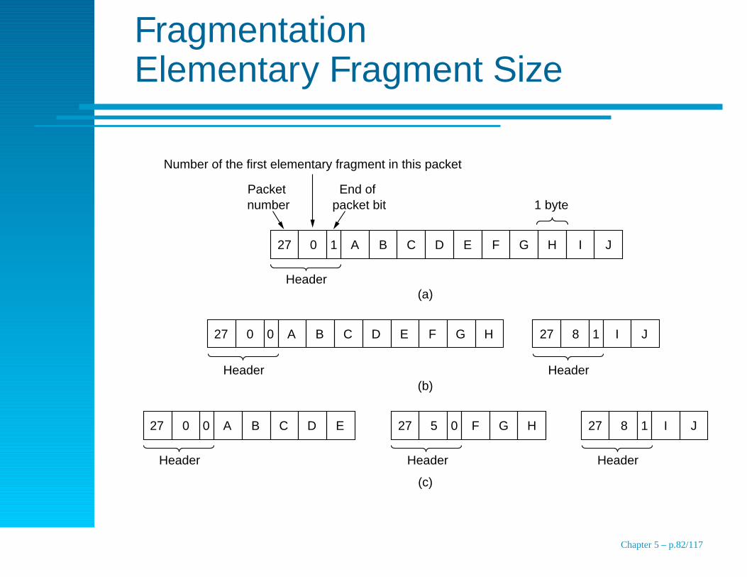
FragmentationElementary Fragment Size
Number of the first elementary fragment in this packet
Packet number
End of packet bit
27 0 1 A B C D E F G H I J
27 0 0 A B C D E F G H 27 8 1 I J
27 0 0 A B C D E 27 5 0 F G H 27 8 1 I J
Header
1 byte
Header Header
Header Header Header
(a)
(b)
(c)
Chapter 5 – p.82/117
Topics
End-to-end transmission, routing
Design Issues
Routing Algorithms
Congestion Control Algorithms
Quality of Service
Internetworking
The Network Layer in the Internet
Chapter 5 – p.83/117
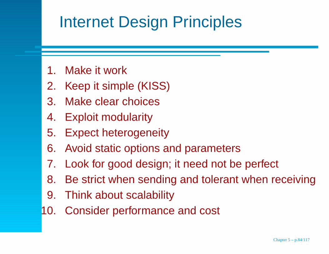
Internet Design Principles
1. Make it work2. Keep it simple (KISS)3. Make clear choices4. Exploit modularity5. Expect heterogeneity6. Avoid static options and parameters7. Look for good design; it need not be perfect8. Be strict when sending and tolerant when receiving9. Think about scalability
10. Consider performance and cost
Chapter 5 – p.84/117
The InternetTopics
The IP Protocol
IP Addresses
Internet Control Protocols
OSPF–The Interior Gateway Routing Protocol
BGP–The Exterior Gateway Routing Protocol
Internet Multicast
Mobile IP
IPv6
Chapter 5 – p.85/117
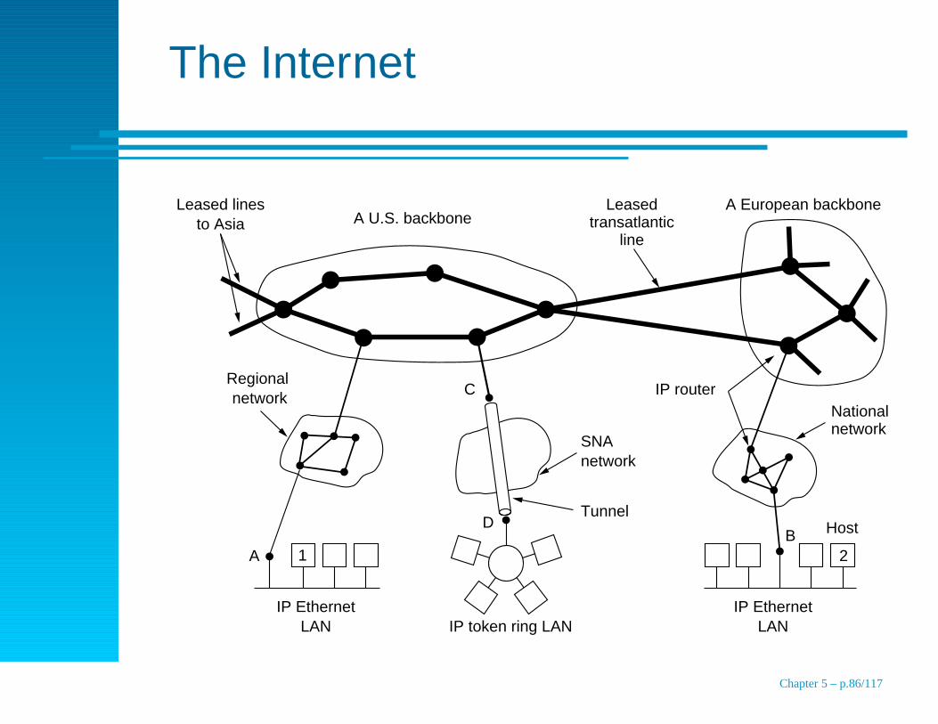
The Internet
Leased lines to Asia A U.S. backbone
Leased transatlantic
line
Regional network
A
IP Ethernet LAN
C
D
SNA network
Tunnel
IP token ring LAN
A European backbone
IP routerNational network
HostB
IP Ethernet LAN
1 2
Chapter 5 – p.86/117
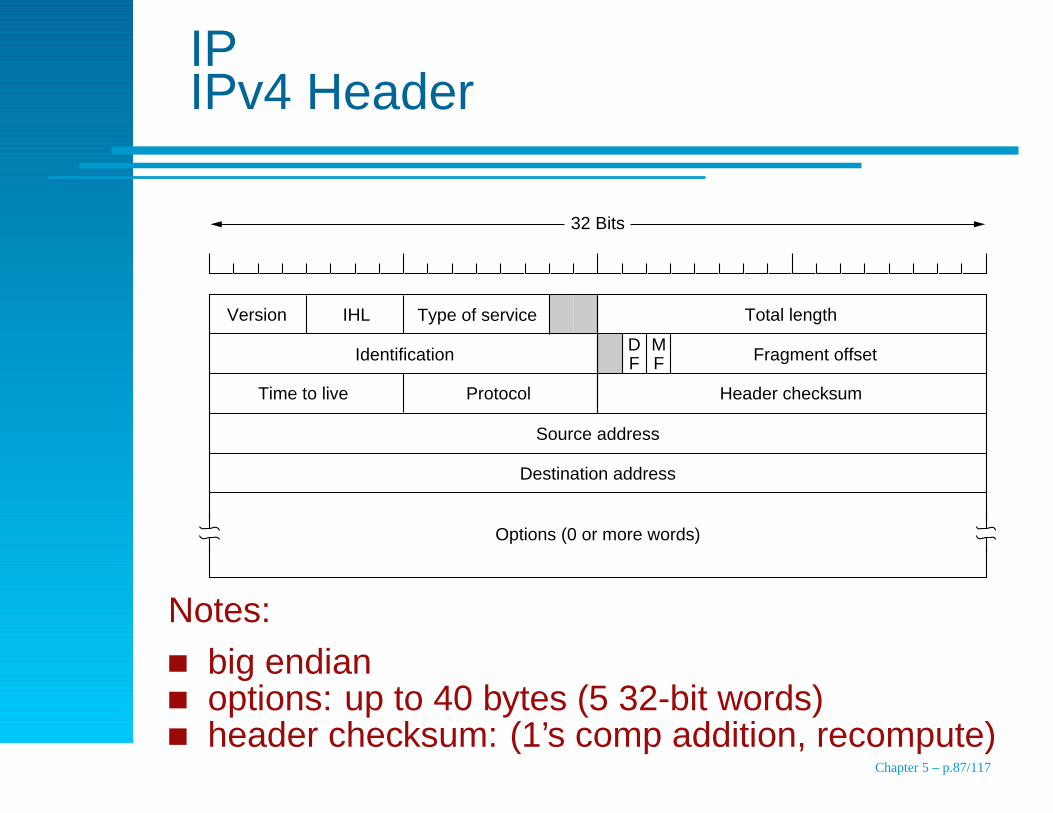
IPIPv4 Header
Version IHL Type of service Total length
Identification
Time to live Protocol
Fragment offset
Header checksum
Source address
Destination address
Options (0 or more words)
D F
M F
32 Bits
Notes:
big endianoptions: up to 40 bytes (5 32-bit words)header checksum: (1’s comp addition, recompute)
Chapter 5 – p.87/117

IPSome Options
Option Description
Security Specifies how secret the datagram is
Strict source routing Gives the complete path to be followed
Loose source routing Gives a list of routers not to be missed
Record route Makes each router append its IP address
Timestamp Makes each router append its address andtimestamp
http://www.iana.org/assignments/parameters
Chapter 5 – p.88/117
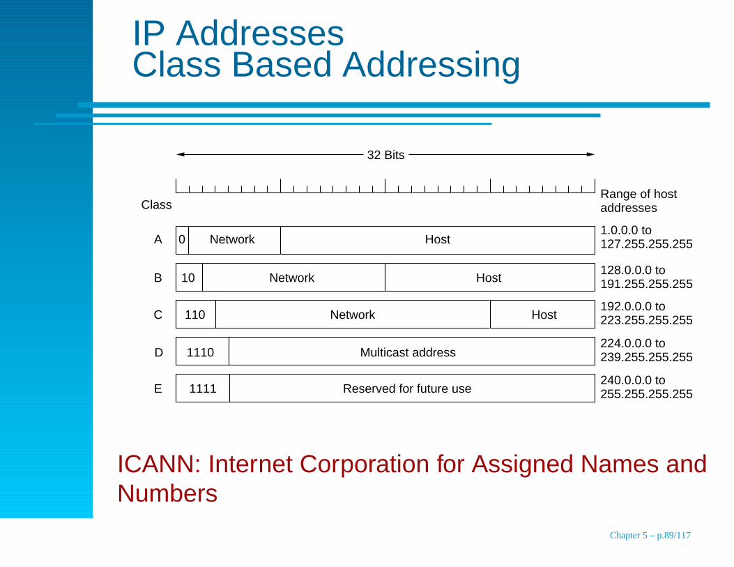
IP AddressesClass Based Addressing
32 Bits
Range of host addresses
1.0.0.0 to 127.255.255.255
128.0.0.0 to 191.255.255.255
192.0.0.0 to 223.255.255.255
224.0.0.0 to 239.255.255.255
240.0.0.0 to 255.255.255.255
Class
0 Network Host
10 Network Host
110 Network Host
1110 Multicast address
1111 Reserved for future use
A
B
C
D
E
ICANN: Internet Corporation for Assigned Names andNumbers
Chapter 5 – p.89/117
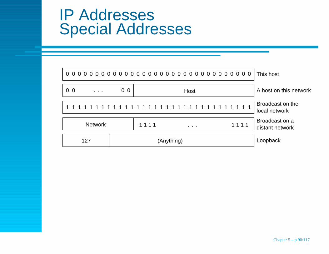
IP AddressesSpecial Addresses
This host
A host on this network
Broadcast on the local network
0
Host
Network
127 (Anything)
Broadcast on a distant network
Loopback
0 0 0 0 0 0 0 0 0 0 0 0 0 0 0 0 0 0 0 0 0 0 0 0 0 0 0 0 0 0 0
1 1 1 1 1 1 1 1 1 1 1 1 1 1 1 1 1 1 1 1 1 1 1 1 1 1 1 1 1 1 1 1
0 0 0 0. . .
. . .1 1 1 1 1 1 1 1
Chapter 5 – p.90/117

IP AddressesIssues
Networks may be too large: subnetworks
Not enough addresses: CIDR
three bears problem
too big, too small, just right is really too big
sparse address space
too many hosts: NAT
ISP with 65,000 subscribers
large corporate network
home network
Chapter 5 – p.91/117
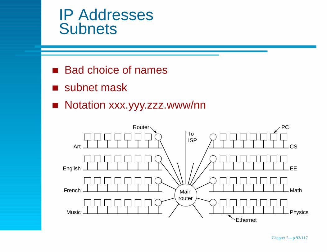
IP AddressesSubnets
Bad choice of names
subnet mask
Notation xxx.yyy.zzz.www/nn
PC
Music
French
English
Art
PhysicsEthernet
Math
To ISP
EE
CS
Router
Main router
Chapter 5 – p.92/117
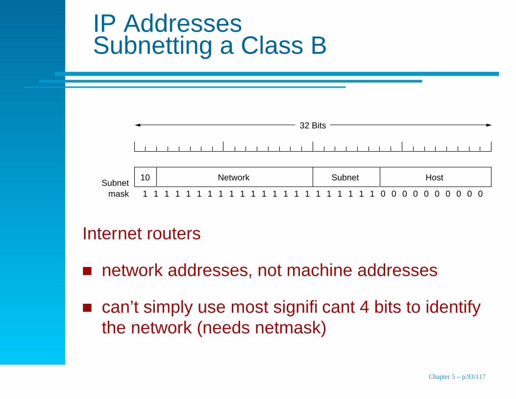
IP AddressesSubnetting a Class B
32 Bits
Subnet mask
10 Network Subnet Host
1 1 1 1 1 1 1 1 1 1 1 1 1 1 1 1 1 1 1 1 1 1 0 0 0 0 0 0 0 0 0 0
Internet routers
network addresses, not machine addresses
can’t simply use most significant 4 bits to identifythe network (needs netmask)
Chapter 5 – p.93/117
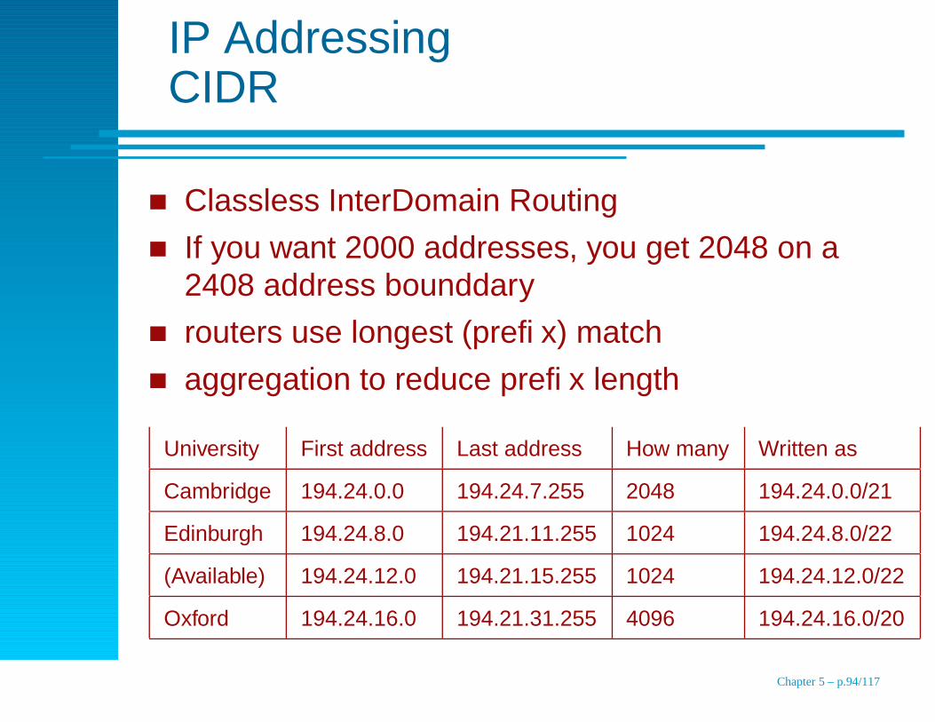
IP AddressingCIDR
Classless InterDomain Routing
If you want 2000 addresses, you get 2048 on a2408 address bounddary
routers use longest (prefix) match
aggregation to reduce prefix length
University First address Last address How many Written as
Cambridge 194.24.0.0 194.24.7.255 2048 194.24.0.0/21
Edinburgh 194.24.8.0 194.21.11.255 1024 194.24.8.0/22
(Available) 194.24.12.0 194.21.15.255 1024 194.24.12.0/22
Oxford 194.24.16.0 194.21.31.255 4096 194.24.16.0/20
Chapter 5 – p.94/117

IP AddressingNAT
NAT–Network Address TranslationUse un-routable addresseslet firewall replace source addressreturning packets? gack!
1
2
3
4
5
6
7NAT box/firewall
PC Leased line
Packet after translation
Packet before translationCompany
LAN
Company router
Server
ISP's router
10.0.0.1 198.60.42.12
Boundary of company premises
Chapter 5 – p.95/117
IP AddressingWhy NAT is wrong
1. Violates IP model (each machine has uniqueaddress)
2. Connections on a connectionless network – NATbox crashes
3. Violates layering principles
4. Assumes particular protocols (TCP and UDP)
5. Some apps put their IP address in the messagebody (FTP)
6. Port limitation is 61,440
Chapter 5 – p.96/117
Control Protocols
ICMP (Internet Control Message Protocol)
ARP (Address Resolution Protocol)
RARP (Reverse ARP), BOOTP (Boot Protocol),DHCP (Dynamic Host Configuration Protocol)
Chapter 5 – p.97/117
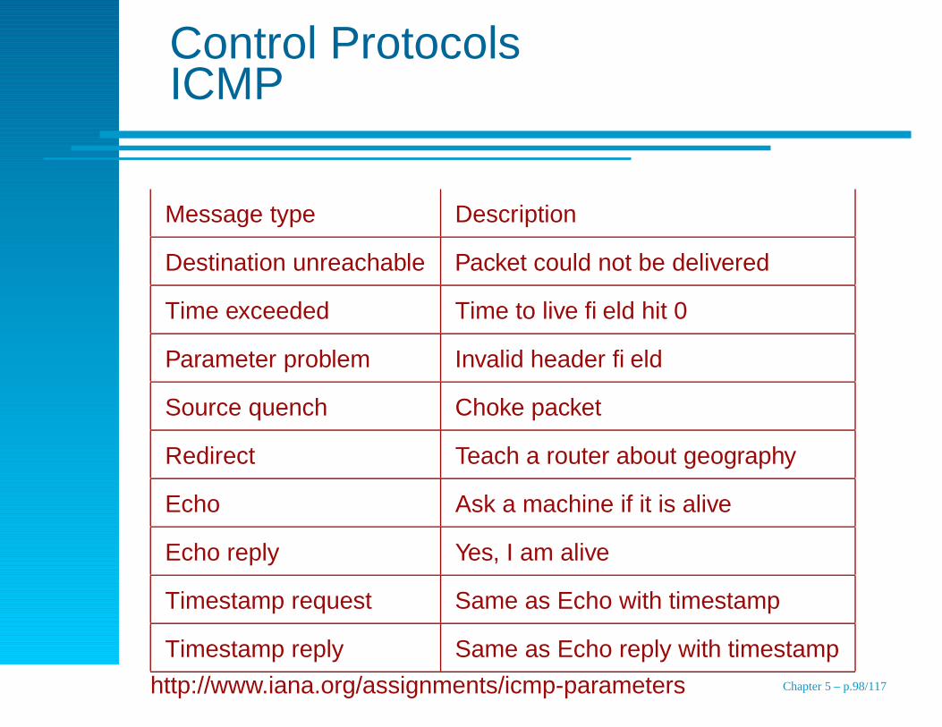
Control ProtocolsICMP
Message type Description
Destination unreachable Packet could not be delivered
Time exceeded Time to live field hit 0
Parameter problem Invalid header field
Source quench Choke packet
Redirect Teach a router about geography
Echo Ask a machine if it is alive
Echo reply Yes, I am alive
Timestamp request Same as Echo with timestamp
Timestamp reply Same as Echo reply with timestamp
http://www.iana.org/assignments/icmp-parameters Chapter 5 – p.98/117

Control ProtocolsARP
RFC 826IP Address to MAC AddressOptimization: bcast IP address on Boot (updateremote ARP caches)Proxy ARP
F2
F1 F3
E1
1 2 3 4
E2 E3 E4 E5 E6
192.31.65.7 192.31.65.5
To
WA
N
CS Router has 2 IP addresses
192.31.60.4192.31.65.1
EE Router has 2 IP addresses
192.31.60.7192.31.63.3
192.31.63.8
Ethernet addresses
Campus FDDI ring
192.31.60.0
CS Ethernet 192.31.65.0
EE Ethernet 192.31.63.0
Chapter 5 – p.99/117
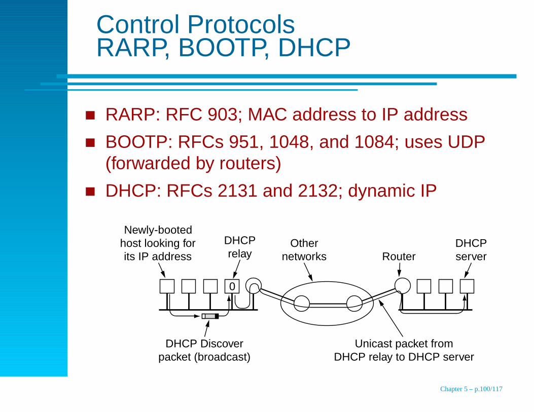
Control ProtocolsRARP, BOOTP, DHCP
RARP: RFC 903; MAC address to IP address
BOOTP: RFCs 951, 1048, and 1084; uses UDP(forwarded by routers)
DHCP: RFCs 2131 and 2132; dynamic IP
Newly-booted host looking for its IP address
DHCP Discover packet (broadcast)
Unicast packet from DHCP relay to DHCP server
DHCP relay
DHCP server
Other
networks
Router
0
Chapter 5 – p.100/117

OSPF
Generalautonomous system
interior versus exterior
OSPF became standard for interior in 1990Requirements
open – published in open literature
must support a variety of distance metrics
adaptable to changes in the network
must use type of service (later dropped)
load balancing by splitting
hierarchical routing
some security
Chapter 5 – p.101/117

OSPFAutonomous system to graph
Kinds of connectionspoint-to-point (router to router)multiaccess networks with/without broadcasting
(a)
(b)
A B C
LAN 1
D
G
E F
JIH
WAN 1
WAN 3
WAN 2
LAN 2
W1
A B C D
G
W2 F
J
W3L1
L2H
2 3
2
4
10 12
6
17
8
13
1
3
16
4
122
E
I3
Chapter 5 – p.102/117

OSPFAreas
A network or set of contiguous networksno overlap
not necessarily exhaustiveBackbone
area 0
all areas are connected to the backbone
each router connected to two or more areas is in the
backboneWithin an area shortest path
all routers in an area have the same link state database
routers that connect multiple areas have database for all
areas
Chapter 5 – p.103/117

OSPF4 Kinds of Routers
AS 1 AS 2
AS 3 AS 4
Internal router
Backbone
Backbone router
Area
Area border router
AS boundary router
BGP protocol connects the ASes
Chapter 5 – p.104/117
OSPFAdjacent Routers
Routers on the same LAN are neighbors
Inefficient to have every router on a LAN talk toevery other router on the LAN
Designated and backup routers
Designated router is adjacent to other routers on itsLAN
Non adjacent routers do not exchange information
Chapter 5 – p.105/117
OSPFMessage Types
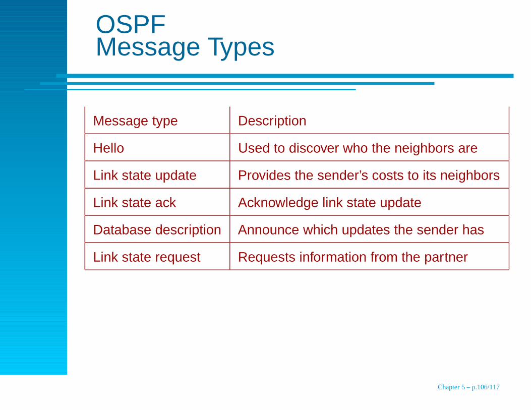
Message type Description
Hello Used to discover who the neighbors are
Link state update Provides the sender’s costs to its neighbors
Link state ack Acknowledge link state update
Database description Announce which updates the sender has
Link state request Requests information from the partner
Chapter 5 – p.106/117

BGP
OSPF recommended within an ASBGP required between ASesOSPF uses any routes
BGP incorporates policiessome routers may refuse to be intermediaries
may want to avoid paths
Kinds of networksstubs – only one BGP connection
multiconnected – refuse to carry transit traffic
transit networks
Chapter 5 – p.107/117

BGP
Like RIP, BGP uses a distance vectorUnlike RIP, BGP exchanges path information
Information F receives from its neighbors about D From B: "I use BCD" From G: "I use GCD" From I: "I use IFGCD" From E: "I use EFGCD"
J
H
D
C
G
I
(a) (b)
F
B
A
E
Chapter 5 – p.108/117
Internet Multicast
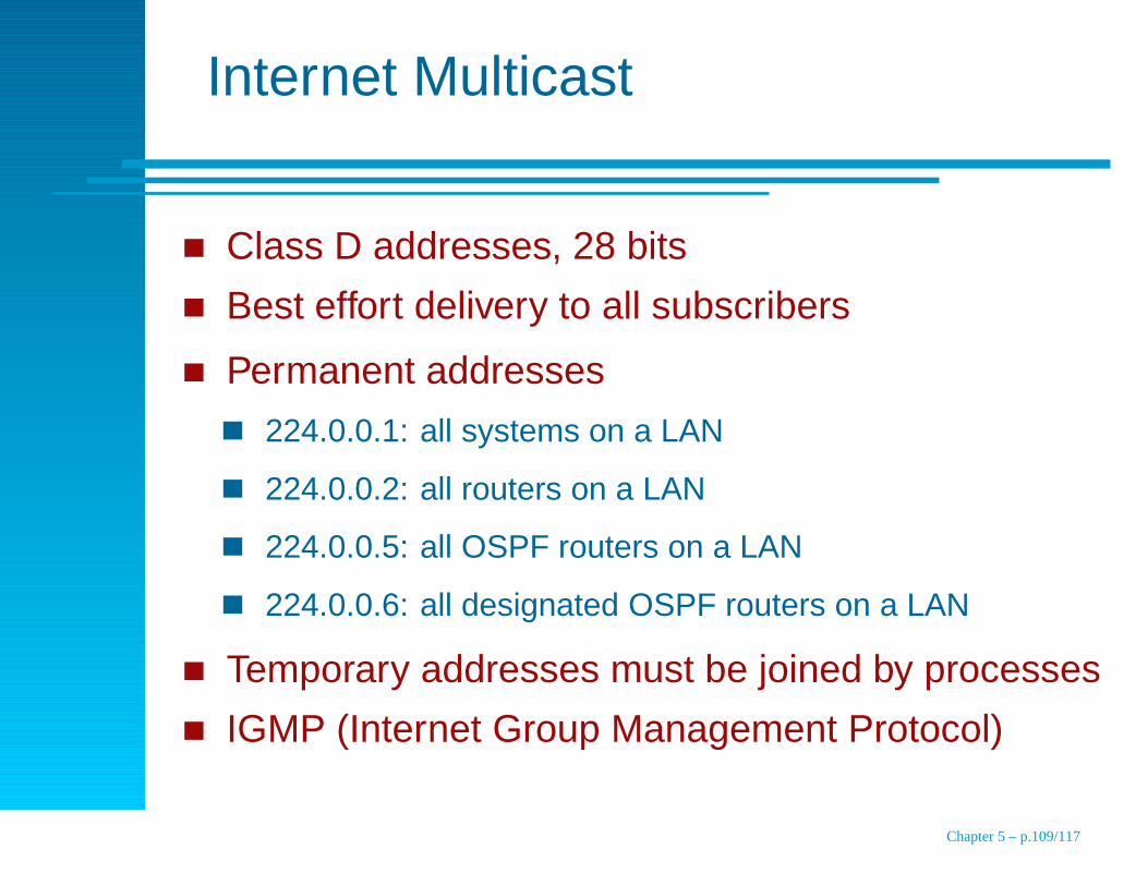
Class D addresses, 28 bits
Best effort delivery to all subscribers
Permanent addresses
224.0.0.1: all systems on a LAN
224.0.0.2: all routers on a LAN
224.0.0.5: all OSPF routers on a LAN
224.0.0.6: all designated OSPF routers on a LAN
Temporary addresses must be joined by processes
IGMP (Internet Group Management Protocol)
Chapter 5 – p.109/117

Mobile IP
Problem: IP address includes network address andhost addressHacks:
give the machine a new IP address for each network
use complete IP address for routing (unlikely)
IETF Working Group goalsmobile hosts can use IP address anywhere
cannot change software on fixed hosts
cannot change routers software or tables
most packets from mobile hosts should not take detours
no overhead when mobile host is at home
Chapter 5 – p.110/117
Mobile IP
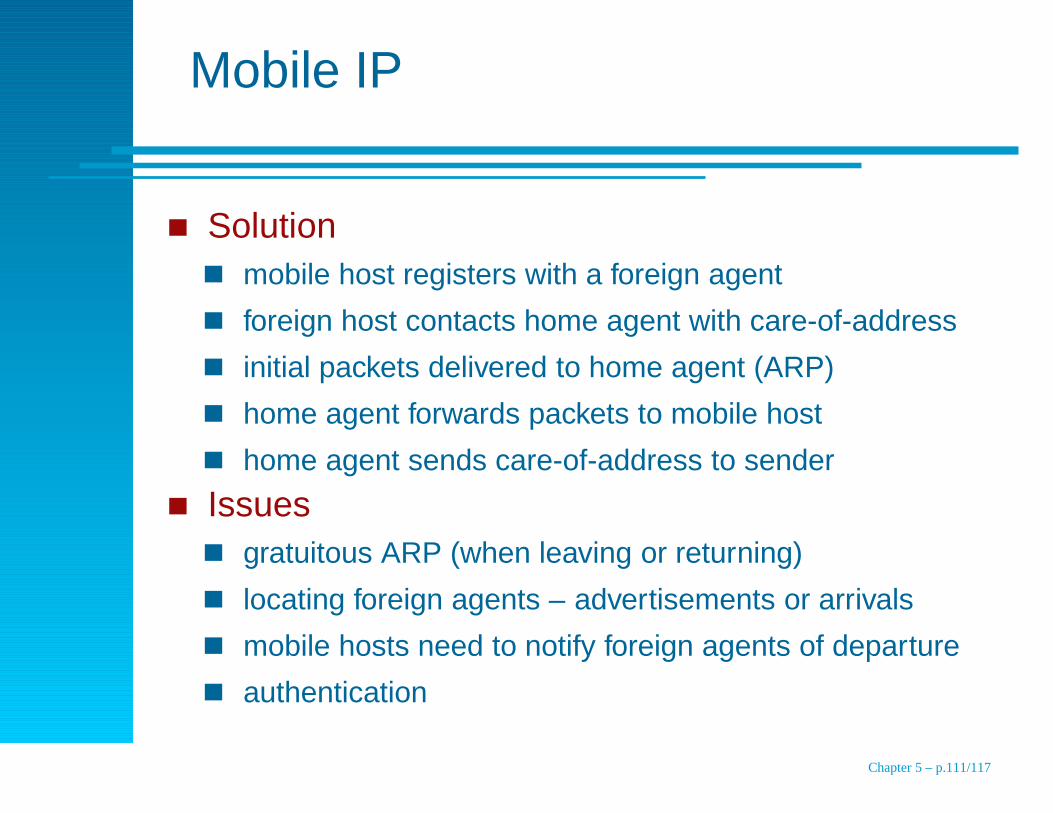
Solutionmobile host registers with a foreign agent
foreign host contacts home agent with care-of-address
initial packets delivered to home agent (ARP)
home agent forwards packets to mobile host
home agent sends care-of-address to sender
Issuesgratuitous ARP (when leaving or returning)
locating foreign agents – advertisements or arrivals
mobile hosts need to notify foreign agents of departure
authentication
Chapter 5 – p.111/117
IPv6Goals
Support billions of hosts (even if address space isinefficient)
Reduce size of routing tables
Simplify protocol for faster processing in routers
Provide better security
Pay more attention to type of service
Aid multicasting by allowing scopes
Allow for future protocol evolution
Permit old and new protocols to co-exist
Chapter 5 – p.112/117
IPv6Results
Longer addresses
Header simplification (7 versus 13 fields)
Better support for options (easier for routers to skip)
Security (many have been retrofitted to IPv4)
Chapter 5 – p.113/117
IPv6Main Header
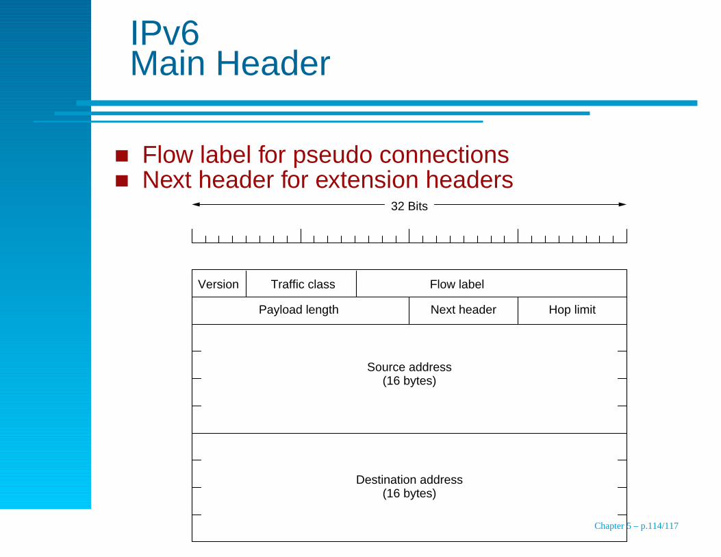
Flow label for pseudo connectionsNext header for extension headers
32 Bits
Version Traffic class Flow label
Payload length Next header Hop limit
Source address (16 bytes)
Destination address (16 bytes)
Chapter 5 – p.114/117
IPv6Lost Fields
IHL field gone, because headers are fixed length
Fragmentation fields removed
Minimum length 576 to 1280 (1024 plus headers)
Header checksum
Chapter 5 – p.115/117
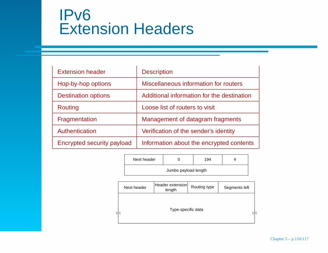
IPv6Extension Headers
Extension header Description
Hop-by-hop options Miscellaneous information for routers
Destination options Additional information for the destination
Routing Loose list of routers to visit
Fragmentation Management of datagram fragments
Authentication Verification of the sender’s identity
Encrypted security payload Information about the encrypted contents
Next header
Jumbo payload length
0 194 4
Next headerHeader extension
lengthRouting type Segments left
Type-specific data
Chapter 5 – p.116/117

IPv6Controversies
Addresses8, 16, 20 bytes? 16 was a compromise
how many addresses per square meter?
how many new addresses per second?8-bit hop count
32 hops are currently common, 255 won’t be enough
header bloat
long haul links, hierarchyMaximum packet sizeRemove header checksumMobile hostsSecurity
Chapter 5 – p.117/117