Embed Size (px)
Citation preview
10/25/2010 Computer Networks 1
Computer Networks
Circuit and Packet Switching
• Circuit switching– Legacy phone network
– Single route through sequence of hardware devices established when two nodes start communication
– Data sent along route
– Route maintained until communication ends
• Packet switching– Internet
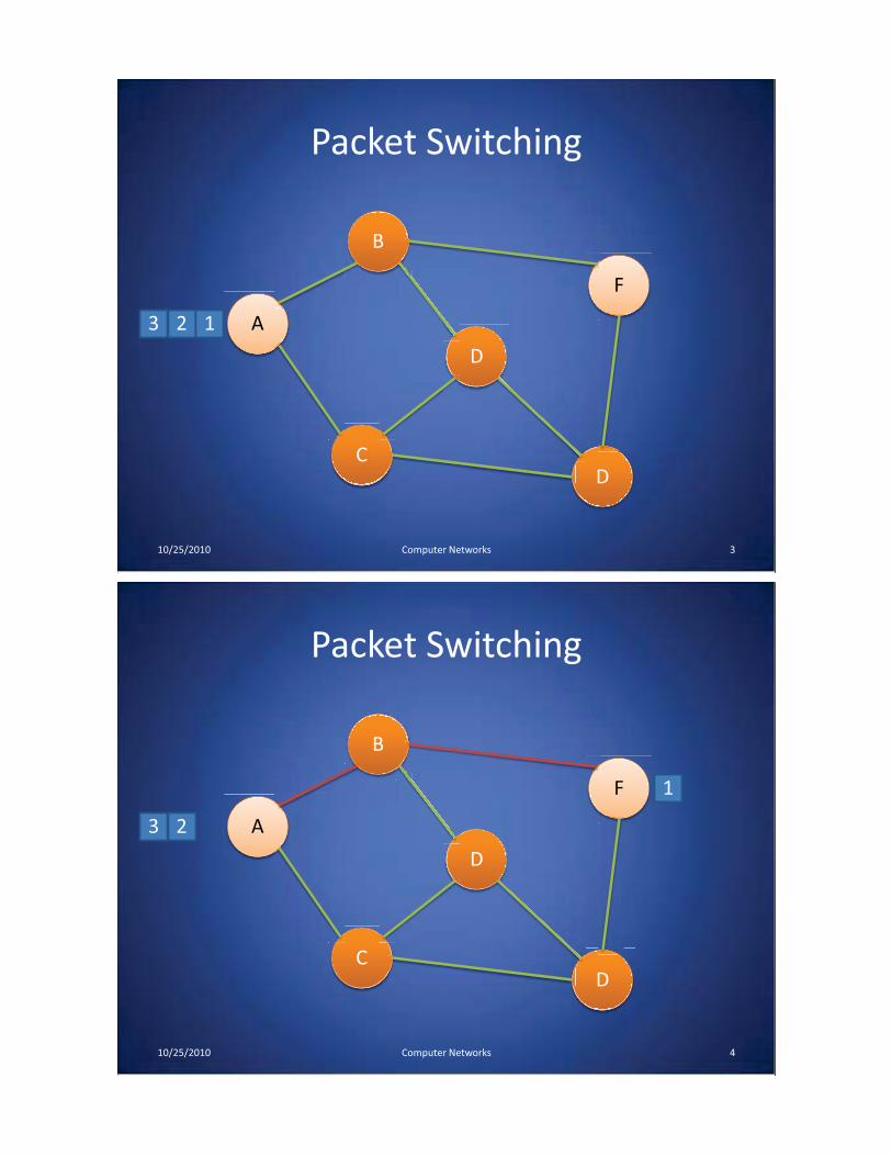
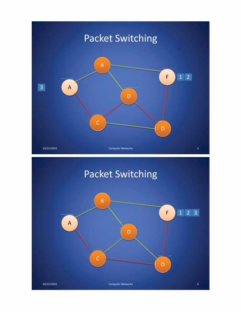
– Data split into packets
– Packets transported independently through network
– Each packet handled on a best efforts basis
– Packets may follow different routes
10/25/2010 Computer Networks 2
Packet Switching
10/25/2010 3Computer Networks
A
C
B
D
F
D
3 2 1
Packet Switching
10/25/2010 4Computer Networks
A
C
B
D
F
D
3 2
1
Packet Switching
10/25/2010 5Computer Networks
A
C
B
D
F
D
3
21
Packet Switching
10/25/2010 6Computer Networks
A
C
B
D
F
D
321
Protocols
• A protocol defines the rules for communication between computers
• Protocols are broadly classified as connectionless and connection oriented
• Connectionless protocol – Sends data out as soon as there is enough data to be transmitted
– E.g., user datagram protocol (UDP)
• Connection-oriented protocol– Provides a reliable connection stream between two nodes– Consists of set up, transmission, and tear down phases– Creates virtual circuit-switched network– E.g., transmission control protocol (TCP)
10/25/2010 Computer Networks 7
Encapsulation• A packet typically consists of
– Control information for addressing the packet: header and footer
– Data: payload
• A network protocol N1 can use the services of another network protocol N2– A packet p1 of N1 is encapsulated into a packet p2 of N2
– The payload of p2 is p1
– The control information of p2 is derived from that of p1
10/25/2010 Computer Networks 8
Header
Payload
FooterHeader Payload Footer
Network Layers
• Network models typically use a stack of layers– Higher layers use the services of lower layers via
encapsulation
– A layer can be implemented in hardware or software
– The bottommost layer must be in hardware
• A network device may implement several layers
• A communication channel between two nodes is established for each layer– Actual channel at the bottom layer
– Virtual channel at higher layers
10/25/2010 Computer Networks 9
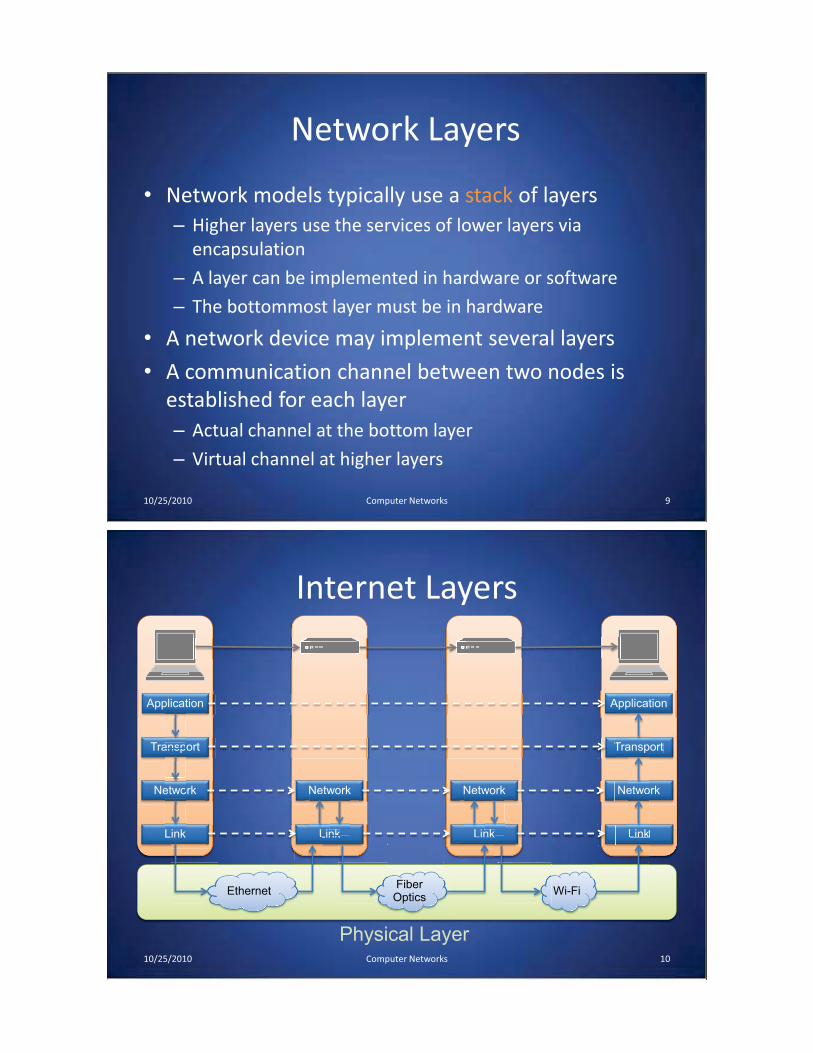
Internet Layers
10/25/2010 10Computer Networks
Application
Transport
Network
Link
etwo
Link
ansp
Application
Transport
Network
Link
ansp
etwo
plicat
Network
Linknk
Netw Network
Linknk
Netw
EthernetFiber
OpticsWi-Fi
L Linknk Link
Physical Layer
T
A

Intermediate Layers• Link layer
– Local area network: Ethernet, WiFi, optical fiber
– 48-bit media access control (MAC) addresses
– Packets called frames
• Network layer– Internet-wide communication
– Best efforts
– 32-bit internet protocol (IP) addresses in IPv4
– 128-bit IP addresses in IPv6
• Transport layer– 16-bit addresses (ports) for classes of applications
– Connection-oriented transmission layer protocol (TCP)
– Connectionless user datagram protocol (UDP)
10/25/2010 Computer Networks 11
Internet Packet Encapsulation
10/25/2010 Computer Networks 12
Application Packet
TCP DataTCP
Header
IPHeader
FrameHeader
FrameFooter Link Layer
Network Layer
Transport Layer
r IP Data
Frame Data
Application Layer
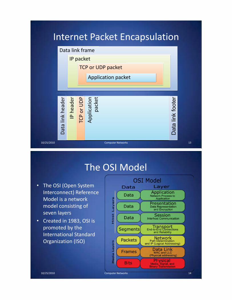
Internet Packet Encapsulation
10/25/2010 13Computer Networks
Data link frame
IP packet
TCP or UDP packet
Application packet
Dat
a lin
k he
ader
IP h
eade
r
TCP
or U
DP
head
erhe
ader
App
licat
ion
pack
et
Data
lin
k f
oote
rThe OSI Model
• The OSI (Open System Interconnect) Reference Model is a network model consisting of seven layers
• Created in 1983, OSI is promoted by the International Standard Organization (ISO)
10/25/2010 Computer Networks 14

Network Interfaces
• Network interface: device connecting a computer to a network– Ethernet card– WiFi adapter
• A computer may have multiple network interfaces• Packets transmitted between network interfaces• Most local area networks, (including Ethernet and WiFi)
broadcast frames• In regular mode, each network interface gets the frames
intended for it• Traffic sniffing can be accomplished by configuring the
network interface to read all frames (promiscuous mode)
10/25/2010 Computer Networks 15
MAC Addresses
• Most network interfaces come with a predefined MAC address • A MAC address is a 48-bit number usually represented in hex
– E.g., 00-1A-92-D4-BF-86
• The first three octets of any MAC address are IEEE-assigned Organizationally Unique Identifiers– E.g., Cisco 00-1A-A1, D-Link 00-1B-11, ASUSTek 00-1A-92
• The next three can be assigned by organizations as they please, with uniqueness being the only constraint
• Organizations can utilize MAC addresses to identify computers on their network
• MAC address can be reconfigured by network interface driver software
10/25/2010 Computer Networks 16
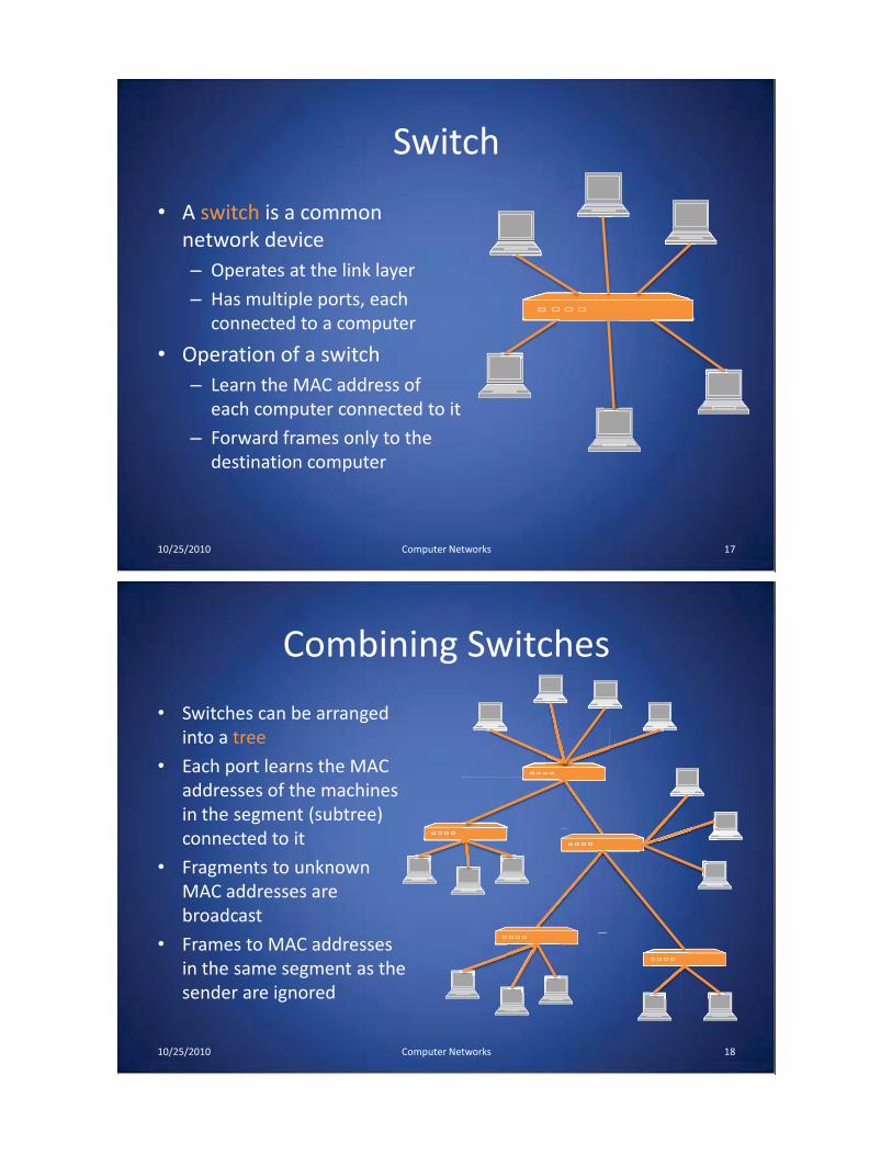
Switch
• A switch is a common network device– Operates at the link layer
– Has multiple ports, each connected to a computer
• Operation of a switch– Learn the MAC address of
each computer connected to it
– Forward frames only to the destination computer
10/25/2010 Computer Networks 17
Combining Switches
• Switches can be arranged into a tree
• Each port learns the MAC addresses of the machines in the segment (subtree) connected to it
• Fragments to unknown MAC addresses are broadcast
• Frames to MAC addresses in the same segment as the sender are ignored
10/25/2010 Computer Networks 18
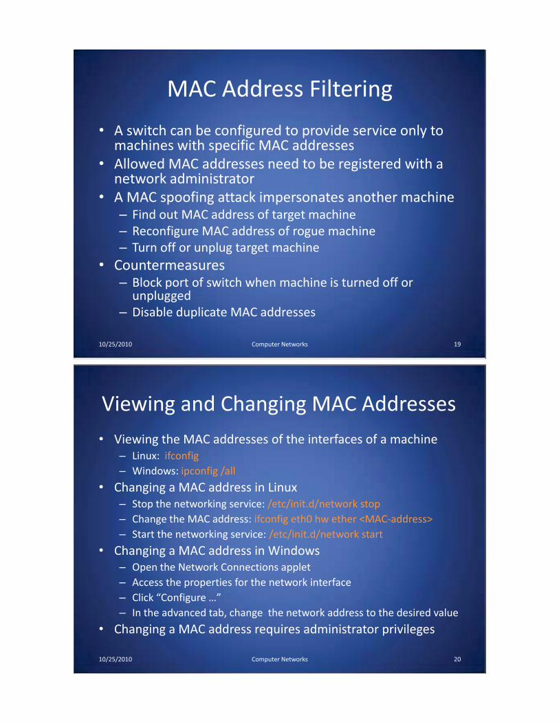
MAC Address Filtering
• A switch can be configured to provide service only to machines with specific MAC addresses
• Allowed MAC addresses need to be registered with a network administrator
• A MAC spoofing attack impersonates another machine– Find out MAC address of target machine– Reconfigure MAC address of rogue machine– Turn off or unplug target machine
• Countermeasures– Block port of switch when machine is turned off or
unplugged– Disable duplicate MAC addresses
10/25/2010 Computer Networks 19
Viewing and Changing MAC Addresses• Viewing the MAC addresses of the interfaces of a machine
– Linux: ifconfig– Windows: ipconfig /all
• Changing a MAC address in Linux– Stop the networking service: /etc/init.d/network stop– Change the MAC address: ifconfig eth0 hw ether <MAC-address>– Start the networking service: /etc/init.d/network start
• Changing a MAC address in Windows– Open the Network Connections applet– Access the properties for the network interface– Click “Configure …”– In the advanced tab, change the network address to the desired value
• Changing a MAC address requires administrator privileges
10/25/2010 Computer Networks 20
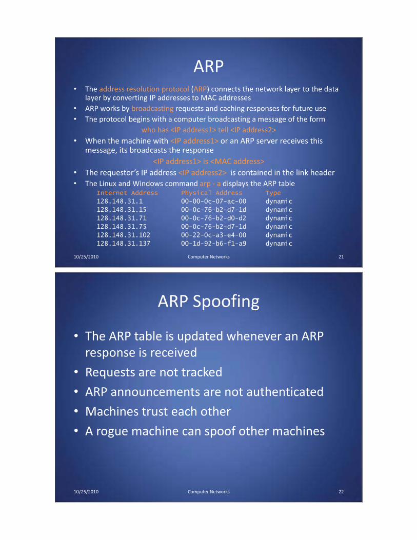
ARP• The address resolution protocol (ARP) connects the network layer to the data
layer by converting IP addresses to MAC addresses• ARP works by broadcasting requests and caching responses for future use• The protocol begins with a computer broadcasting a message of the form
who has <IP address1> tell <IP address2>• When the machine with <IP address1> or an ARP server receives this
message, its broadcasts the response<IP address1> is <MAC address>
• The requestor’s IP address <IP address2> is contained in the link header• The Linux and Windows command arp - a displays the ARP table
Internet Address Physical Address Type
128.148.31.1 00-00-0c-07-ac-00 dynamic
128.148.31.15 00-0c-76-b2-d7-1d dynamic
128.148.31.71 00-0c-76-b2-d0-d2 dynamic
128.148.31.75 00-0c-76-b2-d7-1d dynamic
128.148.31.102 00-22-0c-a3-e4-00 dynamic
128.148.31.137 00-1d-92-b6-f1-a9 dynamic
10/25/2010 Computer Networks 21
ARP Spoofing
• The ARP table is updated whenever an ARP response is received
• Requests are not tracked
• ARP announcements are not authenticated
• Machines trust each other
• A rogue machine can spoof other machines
10/25/2010 Computer Networks 22
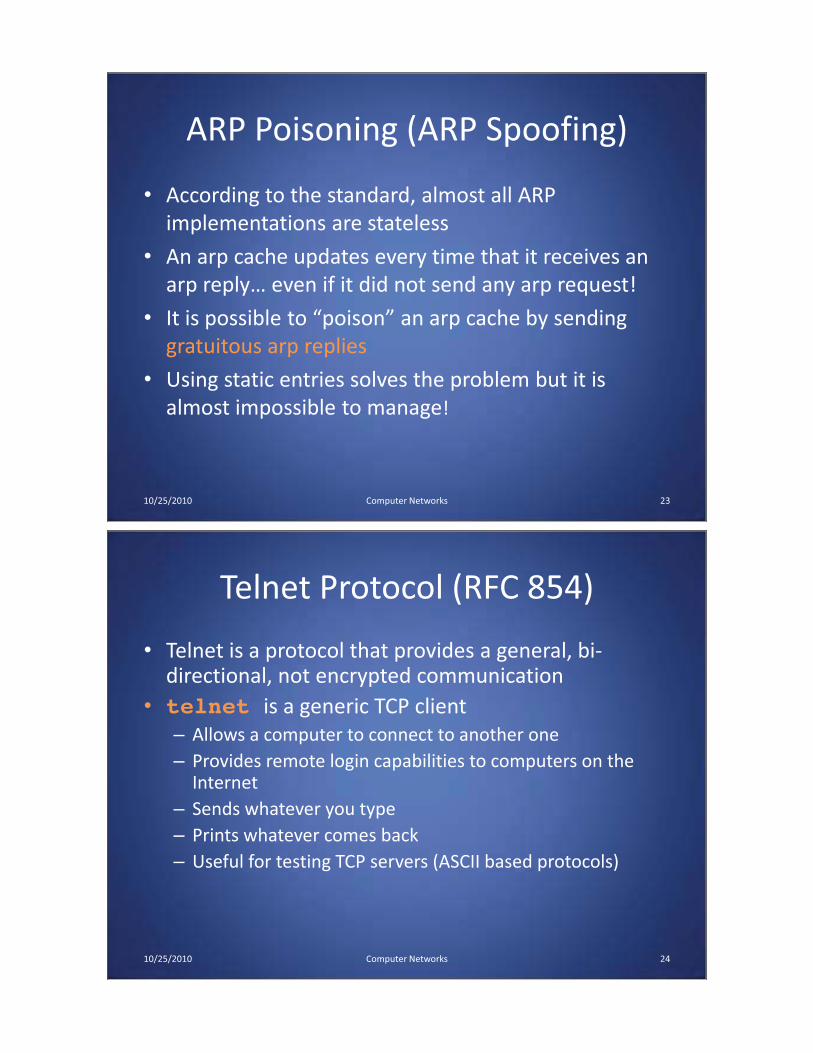
ARP Poisoning (ARP Spoofing)
• According to the standard, almost all ARP implementations are stateless
• An arp cache updates every time that it receives an arp reply… even if it did not send any arp request!
• It is possible to “poison” an arp cache by sending gratuitous arp replies
• Using static entries solves the problem but it is almost impossible to manage!
10/25/2010 Computer Networks 23
Telnet Protocol (RFC 854)
• Telnet is a protocol that provides a general, bi-directional, not encrypted communication
• telnet is a generic TCP client– Allows a computer to connect to another one– Provides remote login capabilities to computers on the
Internet– Sends whatever you type– Prints whatever comes back– Useful for testing TCP servers (ASCII based protocols)
10/25/2010 Computer Networks 24
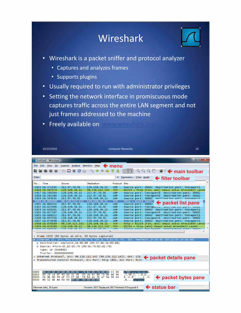
Wireshark
• Wireshark is a packet sniffer and protocol analyzer• Captures and analyzes frames
• Supports plugins
• Usually required to run with administrator privileges
• Setting the network interface in promiscuous mode captures traffic across the entire LAN segment and not just frames addressed to the machine
• Freely available on www.wireshark.org
10/25/2010 Computer Networks 25
�� menu� main toolbar
� filter toolbar
� packet list pane
� packet details pane
� packet bytes pane
� status bar 26
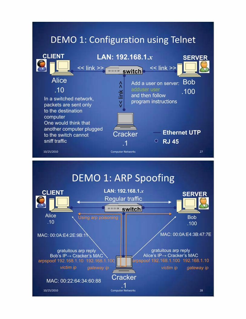
DEMO 1: Configuration using Telnet
10/25/2010 Computer Networks 27
Alice Bob
Cracker
LAN: 192.168.1.x
.10 .100
CLIENT SERVER
switch<< link >> << link >>
<<
lin
k >
>
.1 RJ 45
Ethernet UTP
In a switched network,
packets are sent only
to the destination
computer
One would think that
another computer plugged
to the switch cannot
sniff traffic
Add a user on server:
adduser userand then follow program instructions
DEMO 1: ARP Spoofing
10/25/2010 Computer Networks 28
Alice Bob
Cracker
gratuitous arp replyBob’s IP����������� �
arpspoof 192.168.1.10 192.168.1.100
Regular traffic
Using arp poisoning
LAN: 192.168.1.x
.10 .100
CLIENT SERVER
switch
us arp reply��������� �1.10 192.168.1.100
UsU ing arp poisoning
switch
U
.1
MAC: 00:0A:E4:2E:9B:11
MAC: 00:22:64:34:60:88
gratuitous arp replyAlice’s IP����������� �
arpspoof 192.168.1.100 192.168.1.10
MAC: 00:0A:E4:3B:47:7E
victim ip victim ipgateway ip gateway ip

DEMO 1: catch telnet password
10/25/2010 Computer Networks 29
Alice Bob
Cracker
Regular traffic
Using arp poisoning
LAN: 192.168.1.x
.10 .100
CLIENT SERVER
switch
Using arp poisoning
switchh
Acts as a router
.1
With dsniff, we catch the passwords used to log in to a telnet service:dsniff -n
ARP Caches
10/25/2010 Computer Networks 30
IP: 192.168.1.1MAC: 00:11:22:33:44:01
IP: 192.168.1.105MAC: 00:11:22:33:44:02
ARP Cache
192.168.1.105 00:11:22:33:44:02
ARP Cache
192.168.1.1 00:11:22:33:44:01
Data
192.168.1.1 is at 00:11:22:33:44:0100:11:22:33:44:01192.168.1.105 is at 00:11:22:33:44:02
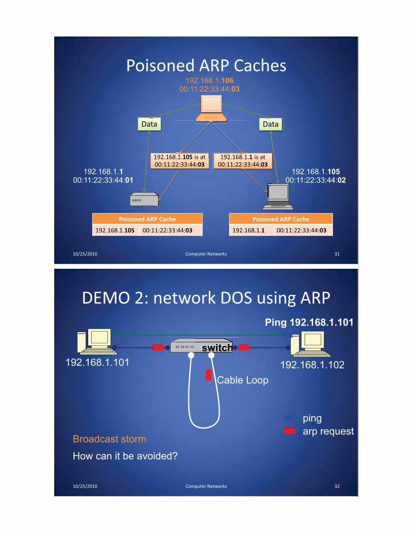
Poisoned ARP Caches
10/25/2010 Computer Networks 31
192.168.1.105 is at 00:11:22:33:44:03
Poisoned ARP Cache
192.168.1.1 00:11:22:33:44:03
Poisoned ARP Cache
192.168.1.105 00:11:22:33:44:03
Data Data
1 105 is at 192.168.1.1 is at 00:11:22:33:44:03192 168 1
192.168.1.100:11:22:33:44:01
192.168.1.10500:11:22:33:44:02
192.168.1.10600:11:22:33:44:03
DEMO 2: network DOS using ARP
10/25/2010 Computer Networks 32
192.168.1.101
switch
192.168.1.102
Cable Loop
Ping 192.168.1.101
arp request
ping
How can it be avoided?
Broadcast storm


![MANUAL · 2021. 3. 1. · Reference number: 2018-1-SE01-KA203-039079. This project has been funded with support from the European Commission. This publication [communication] reflects](https://img.pdfslide.us/doc/110x75/61388efb0ad5d206764953c0/manual-2021-3-1-reference-number-2018-1-se01-ka203-039079-this-project-has.jpg)