Embed Size (px)
Citation preview

Computer Networking : Principles,Protocols and Practice
Release 0.25
Olivier Bonaventure
October 30, 2011
Saylor URL: http://www.saylor.org/courses/cs402/ The Saylor Foundation

Saylor URL: http://www.saylor.org/courses/cs402/ The Saylor Foundation

Contents
1 Preface 3
2 Introduction 52.1 Services and protocols . . . . . . . . . . . . . . . . . . . . . . . . . . . . . . . . . . . . . . . . 112.2 The reference models . . . . . . . . . . . . . . . . . . . . . . . . . . . . . . . . . . . . . . . . 202.3 Organisation of the book . . . . . . . . . . . . . . . . . . . . . . . . . . . . . . . . . . . . . . . 25
3 The application Layer 273.1 Principles . . . . . . . . . . . . . . . . . . . . . . . . . . . . . . . . . . . . . . . . . . . . . . . 273.2 Application-level protocols . . . . . . . . . . . . . . . . . . . . . . . . . . . . . . . . . . . . . 323.3 Writing simple networked applications . . . . . . . . . . . . . . . . . . . . . . . . . . . . . . . 553.4 Summary . . . . . . . . . . . . . . . . . . . . . . . . . . . . . . . . . . . . . . . . . . . . . . . 613.5 Exercises . . . . . . . . . . . . . . . . . . . . . . . . . . . . . . . . . . . . . . . . . . . . . . . 61
4 The transport layer 674.1 Principles of a reliable transport protocol . . . . . . . . . . . . . . . . . . . . . . . . . . . . . . 674.2 The User Datagram Protocol . . . . . . . . . . . . . . . . . . . . . . . . . . . . . . . . . . . . . 874.3 The Transmission Control Protocol . . . . . . . . . . . . . . . . . . . . . . . . . . . . . . . . . 894.4 Summary . . . . . . . . . . . . . . . . . . . . . . . . . . . . . . . . . . . . . . . . . . . . . . . 1134.5 Exercises . . . . . . . . . . . . . . . . . . . . . . . . . . . . . . . . . . . . . . . . . . . . . . . 114
5 The network layer 1275.1 Principles . . . . . . . . . . . . . . . . . . . . . . . . . . . . . . . . . . . . . . . . . . . . . . . 1275.2 Internet Protocol . . . . . . . . . . . . . . . . . . . . . . . . . . . . . . . . . . . . . . . . . . . 1405.3 Routing in IP networks . . . . . . . . . . . . . . . . . . . . . . . . . . . . . . . . . . . . . . . . 1705.4 Summary . . . . . . . . . . . . . . . . . . . . . . . . . . . . . . . . . . . . . . . . . . . . . . . 1955.5 Exercises . . . . . . . . . . . . . . . . . . . . . . . . . . . . . . . . . . . . . . . . . . . . . . . 195
6 The datalink layer and the Local Area Networks 2116.1 Principles . . . . . . . . . . . . . . . . . . . . . . . . . . . . . . . . . . . . . . . . . . . . . . . 2116.2 Medium Access Control . . . . . . . . . . . . . . . . . . . . . . . . . . . . . . . . . . . . . . . 2146.3 Datalink layer technologies . . . . . . . . . . . . . . . . . . . . . . . . . . . . . . . . . . . . . 2286.4 Summary . . . . . . . . . . . . . . . . . . . . . . . . . . . . . . . . . . . . . . . . . . . . . . . 2466.5 Exercises . . . . . . . . . . . . . . . . . . . . . . . . . . . . . . . . . . . . . . . . . . . . . . . 246
7 Glossary 249
8 Bibliography 255
iSaylor URL: http://www.saylor.org/courses/cs402/ The Saylor Foundation

9 Indices and tables 257
Bibliography 259
Index 273
iiSaylor URL: http://www.saylor.org/courses/cs402/ The Saylor Foundation

Computer Networking : Principles, Protocols and Practice, Release 0.25
Contents 1Saylor URL: http://www.saylor.org/courses/cs402/ The Saylor Foundation

Computer Networking : Principles, Protocols and Practice, Release 0.25
2 ContentsSaylor URL: http://www.saylor.org/courses/cs402/ The Saylor Foundation

CHAPTER 1
Preface
This textbook came from a frustration of its main author. Many authors chose to write a textbook because thereare no textbooks in their field or because they are not satisfied with the existing textbooks. This frustrationhas produced several excellent textbooks in the networking community. At a time when networking textbookswere mainly theoretical, Douglas Comer chose to write a textbook entirely focused on the TCP/IP protocol suite[Comer1988], a difficult choice at that time. He later extended his textbook by describing a complete TCP/IPimplementation, adding practical considerations to the theoretical descriptions in [Comer1988]. Richard Stevensapproached the Internet like an explorer and explained the operation of protocols by looking at all the packetsthat were exchanged on the wire [Stevens1994]. Jim Kurose and Keith Ross reinvented the networking textbooksby starting from the applications that the students use and later explained the Internet protocols by removing onelayer after the other [KuroseRoss09].
The frustrations that motivated this book are different. When I started to teach networking in the late 1990s,students were already Internet users, but their usage was limited. Students were still using reference textbooks andspent time in the library. Today’s students are completely different. They are avid and experimented web userswho find lots of information on the web. This is a positive attitude since they are probably more curious thantheir predecessors. Thanks to the information that is available on the Internet, they can check or obtain additionalinformation about the topics explained by their teachers. This abundant information creates several challenges fora teacher. Until the end of the nineteenth century, a teacher was by definition more knowledgeable than his studentsand it was very difficult for the students to verify the lessons given by their teachers. Today, given the amountof information available at the fingertips of each student through the Internet, verifying a lesson or getting moreinformation about a given topic is sometimes only a few clicks away. Websites such as wikipedia provide lots ofinformation on various topics and students often consult them. Unfortunately, the organisation of the informationon these websites is not well suited to allow students to learn from them. Furthermore, there are huge differencesin the quality and depth of the information that is available for different topics.
The second reason is that the computer networking community is a strong participant in the open-source move-ment. Today, there are high-quality and widely used open-source implementations for most networking protocols.This includes the TCP/IP implementations that are part of linux, freebsd or the uIP stack running on 8bits con-trollers, but also servers such as bind, unbound, apache or sendmail and implementations of routing protocols suchas xorp or quagga . Furthermore, the documents that define almost all of the Internet protocols have been devel-oped within the Internet Engineering Task Force (IETF) using an open process. The IETF publishes its protocolspecifications in the publicly available RFC and new proposals are described in Internet drafts.
This open textbook aims to fill the gap between the open-source implementations and the open-source networkspecifications by providing a detailed but pedagogical description of the key principles that guide the operation ofthe Internet. The book is released under a creative commons licence. Such an open-source license is motivatedby two reasons. The first is that we hope that this will allow many students to use the book to learn computernetworks. The second is that I hope that other teachers will reuse, adapt and improve it. Time will tell if it ispossible to build a community of contributors to improve and develop the book further. As a starting point, thefirst release contains all the material for a one-semester first upper undergraduate or a graduate networking course.
As of this writing, most of the text has been written by Olivier Bonaventure. Laurent Vanbever, Virginie Van den
3Saylor URL: http://www.saylor.org/courses/cs402/ The Saylor Foundation

Computer Networking : Principles, Protocols and Practice, Release 0.25
Schriek, Damien Saucez and Mickael Hoerdt have contributed to exercises. Pierre Reinbold designed the iconsused to represent switches and Nipaul Long has redrawn many figures in the SVG format. Stephane Bortzmeyersent many suggestions and corrections to the text. Additional information about the textbook is available athttp://inl.info.ucl.ac.be/CNP3
4 Chapter 1. PrefaceSaylor URL: http://www.saylor.org/courses/cs402/ The Saylor Foundation

CHAPTER 2
Introduction
When the first computers were built during the second world war, they were expensive and isolated. However,after about twenty years, as their prices gradually decreased, the first experiments began to connect computerstogether. In the early 1960s, researchers including Paul Baran, Donald Davies or Joseph Licklider independentlypublished the first papers describing the idea of building computer networks [Baran] [Licklider1963] . Giventhe cost of computers, sharing them over a long distance was an interesting idea. In the US, the ARPANETstarted in 1969 and continued until the mid 1980s [LCCD09]. In France, Louis Pouzin developed the Cycladesnetwork [Pouzin1975]. Many other research networks were built during the 1970s [Moore]. At the same time,the telecommunication and computer industries became interested in computer networks. The telecommunicationindustry bet on the X25. The computer industry took a completely different approach by designing Local AreaNetworks (LAN). Many LAN technologies such as Ethernet or Token Ring were designed at that time. Duringthe 1980s, the need to interconnect more and more computers led most computer vendors to develop their ownsuite of networking protocols. Xerox developed [XNS] , DEC chose DECNet [Malamud1991] , IBM developedSNA [McFadyen1976] , Microsoft introduced NetBIOS [Winston2003] , Apple bet on Appletalk [SAO1990] . Inthe research community, ARPANET was decommissioned and replaced by TCP/IP [LCCD09] and the referenceimplementation was developed inside BSD Unix [McKusick1999]. Universities who were already running Unixcould thus adopt TCP/IP easily and vendors of Unix workstations such as Sun or Silicon Graphics included TCP/IPin their variant of Unix. In parallel, the ISO, with support from the governments, worked on developing an open1 Suite of networking protocols. In the end, TCP/IP became the de facto standard that is not only used within theresearch community. During the 1990s and the early 2000s, the growth of the usage of TCP/IP continued, andtoday proprietary protocols are seldom used. As shown by the figure below, that provides the estimation of thenumber of hosts attached to the Internet, the Internet has sustained large growth throughout the last 20+ years.
Figure 2.1: Estimation of the number of hosts on the Internet
1 Open in ISO terms was in contrast with the proprietary protocol suites whose specification was not always publicly available. The USgovernment even mandated the usage of the OSI protocols (see RFC 1169), but this was not sufficient to encourage all users to switch to theOSI protocol suite that was considered by many as too complex compared to other protocol suites.
5Saylor URL: http://www.saylor.org/courses/cs402/ The Saylor Foundation

Computer Networking : Principles, Protocols and Practice, Release 0.25
Recent estimations of the number of hosts attached to the Internet show a continuing growth since 20+ years.However, although the number of hosts attached to the Internet is high, it should be compared to the numberof mobile phones that are in use today. More and more of these mobile phones will be connected to the Inter-net. Furthermore, thanks to the availability of TCP/IP implementations requiring limited resources such as uIP[Dunkels2003], we can expect to see a growth of TCP/IP enabled embedded devices.
Figure 2.2: Estimation of the number of mobile phones
Before looking at the services provided by computer networks, it is useful to agree on some terminology thatis widely used in networking literature. First of all, computer networks are often classified in function of thegeographical area that they cover
• LAN : a local area network typically interconnects hosts that are up to a few or maybe a few tens of kilome-ters apart.
• MAN : a metropolitan area network typically interconnects devices that are up to a few hundred kilometersapart
• WAN : a wide area network interconnect hosts that can be located anywhere on Earth 2
Another classification of computer networks is based on their physical topology. In the following figures, physicallinks are represented as lines while boxes show computers or other types of networking equipment.
Computer networks are used to allow several hosts to exchange information between themselves. To allow anyhost to send messages to any other host in the network, the easiest solution is to organise them as a full-mesh, witha direct and dedicated link between each pair of hosts. Such a physical topology is sometimes used, especiallywhen high performance and high redundancy is required for a small number of hosts. However, it has two majordrawbacks :
• for a network containing n hosts, each host must have n-1 physical interfaces. In practice, the number ofphysical interfaces on a node will limit the size of a full-mesh network that can be built
• for a network containing n hosts, n×(n−1)2 links are required. This is possible when there are a few nodes
in the same room, but rarely when they are located several kilometers apart
The second possible physical organisation, which is also used inside computers to connect different extensioncards, is the bus. In a bus network, all hosts are attached to a shared medium, usually a cable through a singleinterface. When one host sends an electrical signal on the bus, the signal is received by all hosts attached to the bus.A drawback of bus-based networks is that if the bus is physically cut, then the network is split into two isolatednetworks. For this reason, bus-based networks are sometimes considered to be difficult to operate and maintain,especially when the cable is long and there are many places where it can break. Such a bus-based topology wasused in early Ethernet networks.
A third organisation of a computer network is a star topology. In such topologies, hosts have a single physicalinterface and there is one physical link between each host and the center of the star. The node at the center ofthe star can be either a piece of equipment that amplifies an electrical signal, or an active device, such as a piece
2 In this book, we focus on networks that are used on Earth. These networks sometimes include satellite links. Besides the networktechnologies that are used on Earth, researchers develop networking techniques that could be used between nodes located on different planets.Such an Inter Planetary Internet requires different techniques than the ones discussed in this book. See RFC 4838 and the references thereinfor information about these techniques.
6 Chapter 2. IntroductionSaylor URL: http://www.saylor.org/courses/cs402/ The Saylor Foundation

Computer Networking : Principles, Protocols and Practice, Release 0.25
Figure 2.3: A Full mesh network
Figure 2.4: A network organised as a Bus
of equipment that understands the format of the messages exchanged through the network. Of course, the failureof the central node implies the failure of the network. However, if one physical link fails (e.g. because the cablehas been cut), then only one node is disconnected from the network. In practice, star-shaped networks are easierto operate and maintain than bus-shaped networks. Many network administrators also appreciate the fact thatthey can control the network from a central point. Administered from a Web interface, or through a console-likeconnection, the center of the star is a useful point of control (enabling or disabling devices) and an excellentobservation point (usage statistics).
Figure 2.5: A network organised as a Star
A fourth physical organisation of a network is the Ring topology. Like the bus organisation, each host has a singlephysical interface connecting it to the ring. Any signal sent by a host on the ring will be received by all hostsattached to the ring. From a redundancy point of view, a single ring is not the best solution, as the signal onlytravels in one direction on the ring; thus if one of the links composing the ring is cut, the entire network fails. Inpractice, such rings have been used in local area networks, but are now often replaced by star-shaped networks.In metropolitan networks, rings are often used to interconnect multiple locations. In this case, two parallel links,composed of different cables, are often used for redundancy. With such a dual ring, when one ring fails all thetraffic can be quickly switched to the other ring.
A fifth physical organisation of a network is the tree. Such networks are typically used when a large number ofcustomers must be connected in a very cost-effective manner. Cable TV networks are often organised as trees.
In practice, most real networks combine part of these topologies. For example, a campus network can be organisedas a ring between the key buildings, while smaller buildings are attached as a tree or a star to important buildings.
7Saylor URL: http://www.saylor.org/courses/cs402/ The Saylor Foundation

Computer Networking : Principles, Protocols and Practice, Release 0.25
Figure 2.6: A network organised as a Ring
Figure 2.7: A network organised as a Tree
8 Chapter 2. IntroductionSaylor URL: http://www.saylor.org/courses/cs402/ The Saylor Foundation
Computer Networking : Principles, Protocols and Practice, Release 0.25
Or an ISP network may have a full mesh of devices in the core of its network, and trees to connect remote users.
Throughout this book, our objective will be to understand the protocols and mechanisms that are necessary for anetwork such as the one shown below.
S R
R
R
R
R
R
R
R
RR
R
R
R S
R
tux@linux#
PSTNISP1
ISP2
ISP2
ISP2
alpha.combeta.be
societe.fr
ADSL
Figure 2.8: A simple internetwork
The figure above illustrates an internetwork, i.e. a network that interconnects other networks. Each network isillustrated as an ellipse containing a few devices. We will explain throughout the book the different types ofdevices and their respective roles enabling all hosts to exchange information. As well as this, we will discuss hownetworks are interconnected, and the rules that guide these interconnections. We will also analyse how the bus,ring and mesh topologies are used to build real networks.
The last point of terminology we need to discuss is the transmission modes. When exchanging information througha network, we often distinguish between three transmission modes. In TV and radio transmission, broadcast isoften used to indicate a technology that sends a video or radio signal to all receivers in a given geographical area.Broadcast is sometimes used in computer networks, but only in local area networks where the number of recipientsis limited.
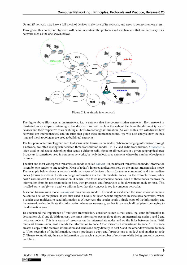
The first and most widespread transmission mode is called unicast . In the unicast transmission mode, informationis sent by one sender to one receiver. Most of today’s Internet applications rely on the unicast transmission mode.The example below shows a network with two types of devices : hosts (drawn as computers) and intermediatenodes (drawn as cubes). Hosts exchange information via the intermediate nodes. In the example below, whenhost S uses unicast to send information, it sends it via three intermediate nodes. Each of these nodes receives theinformation from its upstream node or host, then processes and forwards it to its downstream node or host. Thisis called store and forward and we will see later that this concept is key in computer networks.
A second transmission mode is multicast transmission mode. This mode is used when the same information mustbe sent to a set of recipients. It was first used in LANs but later became supported in wide area networks. Whena sender uses multicast to send information to N receivers, the sender sends a single copy of the information andthe network nodes duplicate this information whenever necessary, so that it can reach all recipients belonging tothe destination group.
To understand the importance of multicast transmission, consider source S that sends the same information todestinations A, C and E. With unicast, the same information passes three times on intermediate nodes 1 and 2 andtwice on node 4. This is a waste of resources on the intermediate nodes and on the links between them. Withmulticast transmission, host S sends the information to node 1 that forwards it downstream to node 2. This nodecreates a copy of the received information and sends one copy directly to host E and the other downstream to node4. Upon reception of the information, node 4 produces a copy and forwards one to node A and another to nodeC. Thanks to multicast, the same information can reach a large number of receivers while being sent only once oneach link.
9Saylor URL: http://www.saylor.org/courses/cs402/ The Saylor Foundation
Computer Networking : Principles, Protocols and Practice, Release 0.25
A
E
S
D
C
B
Figure 2.9: Unicast transmission
A
E
S
D
C
B
Figure 2.10: Multicast transmission
10 Chapter 2. IntroductionSaylor URL: http://www.saylor.org/courses/cs402/ The Saylor Foundation

Computer Networking : Principles, Protocols and Practice, Release 0.25
The last transmission mode is the anycast transmission mode. It was initially defined in RFC 1542. In thistransmission mode, a set of receivers is identified. When a source sends information towards this set of receivers,the network ensures that the information is delivered to one receiver that belongs to this set. Usually, the receiverclosest to the source is the one that receives the information sent by this particular source. The anycast transmissionmode is useful to ensure redundancy, as when one of the receivers fails, the network will ensure that informationwill be delivered to another receiver belonging to the same group. However, in practice supporting the anycasttransmission mode can be difficult.
A
*
S
*
*
B
Figure 2.11: Anycast transmission
In the example above, the three hosts marked with * are part of the same anycast group. When host S sendsinformation to this anycast group, the network ensures that it will reach one of the members of the anycast group.The dashed lines show a possible delivery via nodes 1, 2 and 4. A subsequent anycast transmission from hostS to the same anycast group could reach the host attached to intermediate node 3 as shown by the plain line.An anycast transmission reaches a member of the anycast group that is chosen by the network in function of thecurrent network conditions.
2.1 Services and protocols
An important aspect to understand before studying computer networks is the difference between a service and aprotocol.
In order to understand the difference between the two, it is useful to start with real world examples. The traditionalPost provides a service where a postman delivers letters to recipients. The Post defines precisely which types ofletters (size, weight, etc) can be delivered by using the Standard Mail service. Furthermore, the format of theenvelope is specified (position of the sender and recipient addresses, position of the stamp). Someone who wantsto send a letter must either place the letter at a Post Office or inside one of the dedicated mailboxes. The letterwill then be collected and delivered to its final recipient. Note that for the regular service the Post usually doesnot guarantee the delivery of each particular letter, some letters may be lost, and some letters are delivered to thewrong mailbox. If a letter is important, then the sender can use the registered service to ensure that the letter willbe delivered to its recipient. Some Post services also provide an acknowledged service or an express mail servicethat is faster than the regular service.
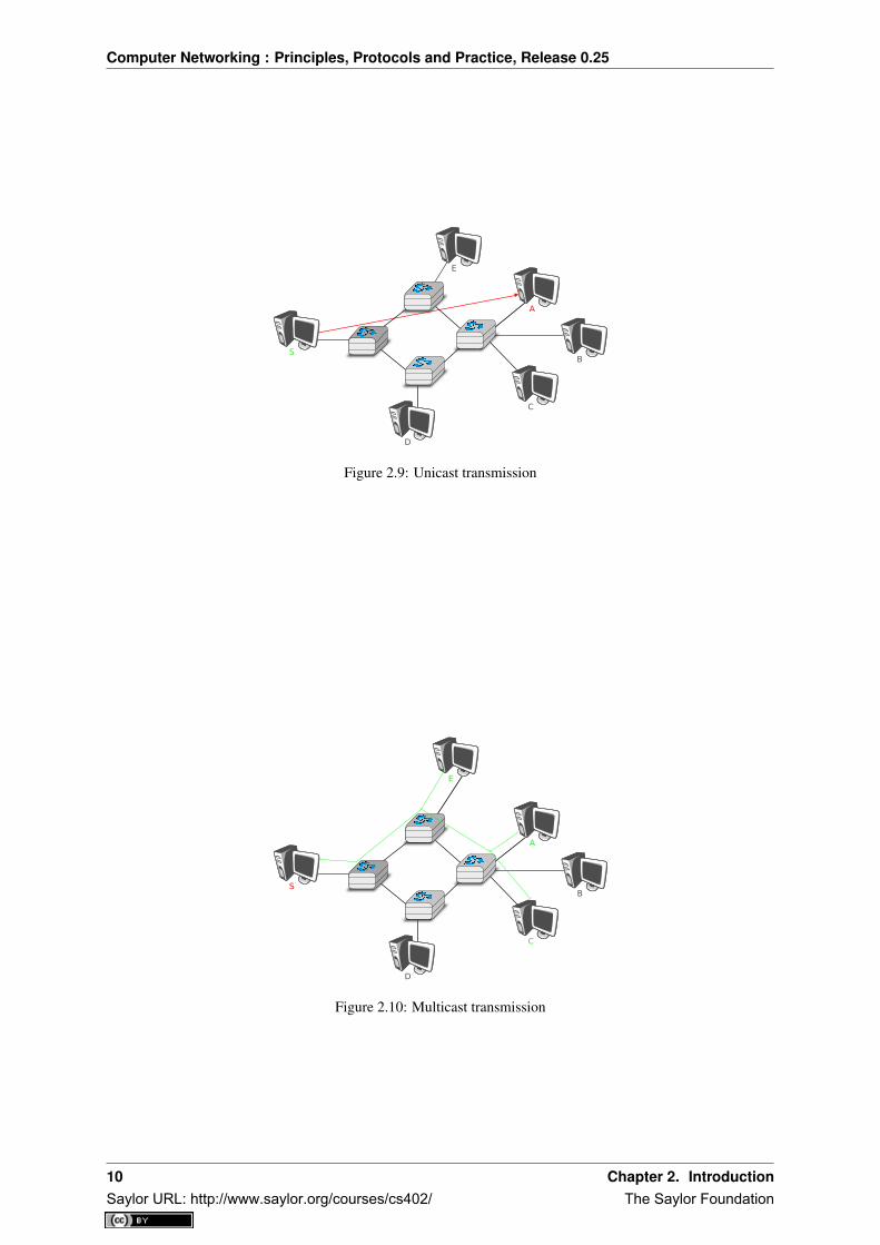
In computer networks, the notion of service is more formally defined in [X200] . It can be better understood byconsidering a computer network, whatever its size or complexity, as a black box that provides a service to users ,as shown in the figure below. These users could be human users or processes running on a computer system.
Many users can be attached to the same service provider. Through this provider, each user must be able toexchange messages with any other user. To be able to deliver these messages, the service provider must be ableto unambiguously identify each user. In computer networks, each user is identified by a unique address, we willdiscuss later how these addresses are built and used. At this point, and when considering unicast transmission, themain characteristic of these addresses is that they are unique. Two different users attached to the network cannotuse the same address.
2.1. Services and protocols 11Saylor URL: http://www.saylor.org/courses/cs402/ The Saylor Foundation
Computer Networking : Principles, Protocols and Practice, Release 0.25
User A User B
Service provider ("the network")
Service Access Point
Primitives
Figure 2.12: Users and service provider
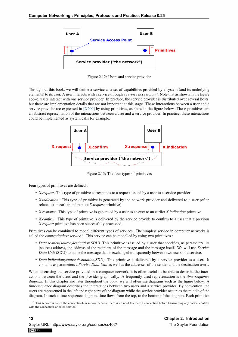
Throughout this book, we will define a service as a set of capabilities provided by a system (and its underlyingelements) to its user. A user interacts with a service through a service access point. Note that as shown in the figureabove, users interact with one service provider. In practice, the service provider is distributed over several hosts,but these are implementation details that are not important at this stage. These interactions between a user and aservice provider are expressed in [X200] by using primitives, as show in the figure below. These primitives arean abstract representation of the interactions between a user and a service provider. In practice, these interactionscould be implemented as system calls for example.
User A User B
Service provider ("the network")
X.indicationX.responseX.confirmX.request
Figure 2.13: The four types of primitives
Four types of primitives are defined :
• X.request. This type of primitive corresponds to a request issued by a user to a service provider
• X.indication. This type of primitive is generated by the network provider and delivered to a user (oftenrelated to an earlier and remote X.request primitive)
• X.response. This type of primitive is generated by a user to answer to an earlier X.indication primitive
• X.confirm. This type of primitive is delivered by the service provide to confirm to a user that a previousX.request primitive has been successfully processed.
Primitives can be combined to model different types of services. The simplest service in computer networks iscalled the connectionless service 3. This service can be modelled by using two primitives :
• Data.request(source,destination,SDU). This primitive is issued by a user that specifies, as parameters, its(source) address, the address of the recipient of the message and the message itself. We will use ServiceData Unit (SDU) to name the message that is exchanged transparently between two users of a service.
• Data.indication(source,destination,SDU). This primitive is delivered by a service provider to a user. Itcontains as parameters a Service Data Unit as well as the addresses of the sender and the destination users.
When discussing the service provided in a computer network, it is often useful to be able to describe the inter-actions between the users and the provider graphically. A frequently used representation is the time-sequencediagram. In this chapter and later throughout the book, we will often use diagrams such as the figure below. Atime-sequence diagram describes the interactions between two users and a service provider. By convention, theusers are represented in the left and right parts of the diagram while the service provider occupies the middle of thediagram. In such a time-sequence diagram, time flows from the top, to the bottom of the diagram. Each primitive
3 This service is called the connectionless service because there is no need to create a connection before transmitting any data in contrastwith the connection-oriented service.
12 Chapter 2. IntroductionSaylor URL: http://www.saylor.org/courses/cs402/ The Saylor Foundation

Computer Networking : Principles, Protocols and Practice, Release 0.25
is represented by a plain horizontal arrow, to which the name of the primitive is attached. The dashed lines areused to represent the possible relationship between two (or more) primitives. Such a diagram provides informationabout the ordering of the different primitives, but the distance between two primitives does not represent a preciseamount of time.
The figure below provides a representation of the connectionless service as a time-sequence diagram. The user onthe left, having address S, issues a Data.request primitive containing SDU M that must be delivered by the serviceprovider to destination D. The dashed line between the two primitives indicates that the Data.indication primitivethat is delivered to the user on the right corresponds to the Data.request primitive sent by the user on the left.
Source Provider Destination
DATA.request(S, D, "M")
DATA.indication(S, D, "M")
Time
Figure 2.14: A simple connectionless service
There are several possible implementations of the connectionless service, which we will discuss later in this book.Before studying these realisations, it is useful to discuss the possible characteristics of the connectionless service.A reliable connectionless service is a service where the service provider guarantees that all SDUs submitted inData.requests by a user will eventually be delivered to their destination. Such a service would be very useful forusers, but guaranteeing perfect delivery is difficult in practice. For this reason, computer networks usually supportan unreliable connectionless service.
An unreliable connectionless service may suffer from various types of problems compared to a reliable connec-tionless service. First of all, an unreliable connectionless service does not guarantee the delivery of all SDUs.This can be expressed graphically by using the time-sequence diagram below.
In practice, an unreliable connectionless service will usually deliver a large fraction of the SDUs. However, sincethe delivery of SDUs is not guaranteed, the user must be able to recover from the loss of any SDU.
A second imperfection that may affect an unreliable connectionless service is that it may duplicate SDUs. Someunreliable connectionless service providers may deliver an SDU sent by a user twice or even more. This isillustrated by the time-sequence diagram below.
Finally, some unreliable connectionless service providers may deliver to a destination a different SDU than theone that was supplied in the Data.request. This is illustrated in the figure below.
When a user interacts with a service provider, it must precisely know the limitations of the underlying service tobe able to overcome any problem that may arise. This requires a precise definition of the characteristics of theunderlying service.
Another important characteristic of the connectionless service is whether it preserves the ordering of the SDUssent by one user. From the user’s viewpoint, this is often a desirable characteristic. This is illustrated in the figurebelow.
However, many connectionless services, and in particular the unreliable services, do not guarantee that they willalways preserve the ordering of the SDUs sent by each user. This is illustrated in the figure below.
2.1. Services and protocols 13Saylor URL: http://www.saylor.org/courses/cs402/ The Saylor Foundation

Computer Networking : Principles, Protocols and Practice, Release 0.25
Source Provider Destination
DATA.request(S, D, "Msg")
Time
Figure 2.15: An unreliable connectionless service may loose SDUs
Source Provider Destination
DATA.request(S, D, "Msg")
DATA.indication(S, D, "Msg")
Time
DATA.indication(S, D, "Msg")
Figure 2.16: An unreliable connectionless service may duplicate SDUs
14 Chapter 2. IntroductionSaylor URL: http://www.saylor.org/courses/cs402/ The Saylor Foundation

Computer Networking : Principles, Protocols and Practice, Release 0.25
Source Provider Destination
DATA.request(S, D, "Msg")
DATA.indication(S, D, "XYZ")
Time
Figure 2.17: An unreliable connectionless service may deliver erroneous SDUs
Figure 2.18: A connectionless service that preserves the ordering of SDUs sent by a given user
Source Provider Destination
Time
DATA.request(S, D, "A")
DATA.indication(S, D, "B")
DATA.request(S, D, "B")
DATA.indication(S, D, "A")
Figure 2.19: A connectionless service that does not preserve the ordering of SDUs sent by a given user
2.1. Services and protocols 15Saylor URL: http://www.saylor.org/courses/cs402/ The Saylor Foundation

Computer Networking : Principles, Protocols and Practice, Release 0.25
The connectionless service is widely used in computer networks as we will see later in this book. Several variationsto this basic service have been proposed. One of these is the confirmed connectionless service. This service usesa Data.confirm primitive in addition to the classical Data.request and Data.indication primitives. This primitiveis issued by the service provider to confirm to a user the delivery of a previously sent SDU to its recipient. Notethat, like the registered service of the post office, the Data.confirm only indicates that the SDU has been deliveredto the destination user. The Data.confirm primitive does not indicate whether the SDU has been processed by thedestination user. This confirmed connectionless service is illustrated in the figure below.
Source Provider Destination
Time
DATA.request(S, D, "M")
DATA.indication(S, D, "M")
DATA.confirm
Figure 2.20: A confirmed connectionless service
The connectionless service we have described earlier is frequently used by users who need to exchange smallSDUs. Users needing to either send or receive several different and potentially large SDUs, or who need structuredexchanges often prefer the connection-oriented service.
An invocation of the connection-oriented service is divided into three phases. The first phase is the establishmentof a connection. A connection is a temporary association between two users through a service provider. Severalconnections may exist at the same time between any pair of users. Once established, the connection is used totransfer SDUs. Connections usually provide one bidirectional stream supporting the exchange of SDUs betweenthe two users that are associated through the connection. This stream is used to transfer data during the secondphase of the connection called the data transfer phase. The third phase is the termination of the connection. Oncethe users have finished exchanging SDUs, they request to the service provider to terminate the connection. As wewill see later, there are also some cases where the service provider may need to terminate a connection itself.
The establishment of a connection can be modelled by using four primitives : Connect.request, Connect.indication,Connect.response and Connect.confirm. The Connect.request primitive is used to request the establishment of aconnection. The main parameter of this primitive is the address of the destination user. The service providerdelivers a Connect.indication primitive to inform the destination user of the connection attempt. If it accepts toestablish a connection, it responds with a Connect.response primitive. At this point, the connection is consideredto be open and the destination user can start sending SDUs over the connection. The service provider processesthe Connect.response and will deliver a Connect.confirm to the user who initiated the connection. The deliveryof this primitive terminates the connection establishment phase. At this point, the connection is considered to beopen and both users can send SDUs. A successful connection establishment is illustrated below.
The example above shows a successful connection establishment. However, in practice not all connections aresuccessfully established. One reason is that the destination user may not agree, for policy or performance reasons,to establish a connection with the initiating user at this time. In this case, the destination user responds to theConnect.indication primitive by a Disconnect.request primitive that contains a parameter to indicate why theconnection has been refused. The service provider will then deliver a Disconnect.indication primitive to informthe initiating user. A second reason is when the service provider is unable to reach the destination user. Thismight happen because the destination user is not currently attached to the network or due to congestion. In these
16 Chapter 2. IntroductionSaylor URL: http://www.saylor.org/courses/cs402/ The Saylor Foundation

Computer Networking : Principles, Protocols and Practice, Release 0.25
Source Provider Destination
Time
CONNECT.request
CONNECT.indication
CONNECT.confirm
CONNECT.response
Source considersconnection open
Destination considersconnection open
Figure 2.21: Connection establishment
cases, the service provider responds to the Connect.request with a Disconnect.indication primitive whose reasonparameter contains additional information about the failure of the connection.
Source Provider Destination
Time
CONNECT.request
CONNECT.indication
DISCONNECT.indication
DISCONNECT.request
Connection rejectedby provider
Connection rejected by destination
CONNECT.request
DISCONNECT.indication
Figure 2.22: Two types of rejection for a connection establishment attempt
Once the connection has been established, the service provider supplies two data streams to the communicatingusers. The first data stream can be used by the initiating user to send SDUs. The second data stream allowsthe responding user to send SDUs to the initiating user. The data streams can be organised in different ways. Afirst organisation is the message-mode transfer. With the message-mode transfer, the service provider guaranteesthat one and only one Data.indication will be delivered to the endpoint of the data stream for each Data.requestprimitive issued by the other endpoint. The message-mode transfer is illustrated in the figure below. The mainadvantage of the message-transfer mode is that the recipient receives exactly the SDUs that were sent by the otheruser. If each SDU contains a command, the receiving user can process each command as soon as it receives aSDU.
Unfortunately, the message-mode transfer is not widely used on the Internet. On the Internet, the most popularconnection-oriented service transfers SDUs in stream-mode. With the stream-mode, the service provider supplies abyte stream that links the two communicating users. The sending user sends bytes by using Data.request primitivesthat contain sequences of bytes as SDUs. The service provider delivers SDUs containing consecutive bytes to thereceiving user by using Data.indication primitives. The service provider ensures that all the bytes sent at one end
2.1. Services and protocols 17Saylor URL: http://www.saylor.org/courses/cs402/ The Saylor Foundation

Computer Networking : Principles, Protocols and Practice, Release 0.25
Source Provider Destination
Time
CONNECT.request
CONNECT.indication
CONNECT.confirm
CONNECT.response
DATA.request("A")
DATA.request("BCD")
DATA.request("EF")
DATA.indication("A")
DATA.indication("BCD")
DATA.indication("EF")
Figure 2.23: Message-mode transfer in a connection oriented service
of the stream are delivered correctly in the same order at the other endpoint. However, the service provider doesnot attempt to preserve the boundaries of the SDUs. There is no relation enforced by the service provider betweenthe number of Data.request and the number of Data.indication primitives. The stream-mode is illustrated in thefigure below. In practice, a consequence of the utilisation of the stream-mode is that if the users want to exchangestructured SDUs, they will need to provide the mechanisms that allow the receiving user to separate successiveSDUs in the byte stream that it receives. As we will see in the next chapter, application layer protocols often usespecific delimiters such as the end of line character to delineate SDUs in a bytestream.
Source Provider Destination
Time
CONNECT.request
CONNECT.indication
CONNECT.confirm
CONNECT.response
DATA.request("AB")
DATA.request("CD")
DATA.request("EF")
DATA.indication("A")
DATA.indication("B")
DATA.indication("C")
DATA.indication("DEF")
Figure 2.24: Stream-mode transfer in a connection oriented service
The third phase of a connection is when it needs to be released. As a connection involves three parties (two usersand one service provider), any of them can request the termination of the connection. Usually, connections areterminated upon request of one user once the data transfer is finished. However, sometimes the service providermay be forced to terminate a connection. This can be due to lack of resources inside the service provider orbecause one of the users is not reachable anymore through the network. In this case, the service provider will issueDisconnect.indication primitives to both users. These primitives will contain, as parameter, some informationabout the reason for the termination of the connection. Unfortunately, as illustrated in the figure below, when a
18 Chapter 2. IntroductionSaylor URL: http://www.saylor.org/courses/cs402/ The Saylor Foundation

Computer Networking : Principles, Protocols and Practice, Release 0.25
service provider is forced to terminate a connection it cannot guarantee that all SDUs sent by each user have beendelivered to the other user. This connection release is said to be abrupt as it can cause losses of data.
Source Provider Destination
Time
DATA.request("A")
DATA.request("B")
DATA.indication("A")
DATA.indication("C")
Connection opened Connection opened
DISCONNECT.indication DISCONNECT.indication
Figure 2.25: Abrupt connection release initiated by the service provider
An abrupt connection release can also be triggered by one of the users. If a user needs, for any reason, to terminatea connection quickly, it can issue a Disconnect.request primitive and to request an abrupt release. The serviceprovider will process the request, stop the two data streams and deliver the Disconnect.indication primitive to theremote user as soon as possible. As illustrated in the figure below, this abrupt connection release may cause lossesof SDUs.
Source Provider Destination
Time
DATA.request("A")
DATA.request("B")
DATA.indication("A")
DATA.request("C")
Connection opened Connection opened
DISCONNECT.req(abrupt)
DISCONNECT.indication
Figure 2.26: Abrupt connection release initiated by a user
To ensure a reliable delivery of the SDUs sent by each user over a connection, we need to consider the two streamsthat compose a connection as independent. A user should be able to release the stream that it uses to send SDUsonce it has sent all the SDUs that it planned to send over this connection, but still continue to receive SDUs overthe opposite stream. This graceful connection release is usually performed as shown in the figure below. One userissues a Disconnect.request primitive to its provider once it has issued all its Data.request primitives. The serviceprovider will wait until all Data.indication primitives have been delivered to the receiving user before issuing theDisconnnect.indication primitive. This primitive informs the receiving user that it will no longer receive SDUsover this connection, but it is still able to issue Data.request primitives on the stream in the opposite direction.Once the user has issued all of its Data.request primitives, it issues a Disconnnect.request primitive to request thetermination of the remaining stream. The service provider will process the request and deliver the correspondingDisconnect.indication to the other user once it has delivered all the pending Data.indication primitives. At this
2.1. Services and protocols 19Saylor URL: http://www.saylor.org/courses/cs402/ The Saylor Foundation

Computer Networking : Principles, Protocols and Practice, Release 0.25
point, all data has been delivered and the two streams have been released successfully and the connection iscompletely closed.
Source Provider Destination
Time
DATA.request("A")
Source -> Destinationconnection closed
Connection opened Connection opened
DATA.request("B") DATA.request("C")
DATA.indication("A")
DATA.indication("B")
DISCONNECT.req(graceful)
DISCONNECT.ind(graceful)DATA.indication("C")
DATA.indication("D")
DATA.request("D")
DISCONNECT.ind(graceful)
DISCONNECT.req(graceful)
Connection closed Connection closed
Figure 2.27: Graceful connection release
Note: Reliability of the connection-oriented service
An important point to note about the connection-oriented service is its reliability. A connection-oriented servicecan only guarantee the correct delivery of all SDUs provided that the connection has been released gracefully. Thisimplies that while the connection is active, there is no guarantee for the actual delivery of the SDUs exchanged asthe connection may need to be released abruptly at any time.
2.2 The reference models
Given the growing complexity of computer networks, during the 1970s network researchers proposed variousreference models to facilitate the description of network protocols and services. Of these, the Open SystemsInterconnection (OSI) model [Zimmermann80] was probably the most influential. It served as the basis for thestandardisation work performed within the ISO to develop global computer network standards. The referencemodel that we use in this book can be considered as a simplified version of the OSI reference model 4.
2.2.1 The five layers reference model
Our reference model is divided into five layers, as shown in the figure below.
Starting from the bottom, the first layer is the Physical layer. Two communicating devices are linked through aphysical medium. This physical medium is used to transfer an electrical or optical signal between two directlyconnected devices. Several types of physical mediums are used in practice :
• electrical cable. Information can be transmitted over different types of electrical cables. The most commonones are the twisted pairs that are used in the telephone network, but also in enterprise networks and coaxialcables. Coaxial cables are still used in cable TV networks, but are no longer used in enterprise networks.Some networking technologies operate over the classical electrical cable.
• optical fiber. Optical fibers are frequently used in public and enterprise networks when the distance be-tween the communication devices is larger than one kilometer. There are two main types of optical fibers: multimode and monomode. Multimode is much cheaper than monomode fiber because a LED can be
4 An interesting historical discussion of the OSI-TCP/IP debate may be found in [Russel06]
20 Chapter 2. IntroductionSaylor URL: http://www.saylor.org/courses/cs402/ The Saylor Foundation

Computer Networking : Principles, Protocols and Practice, Release 0.25
Application
Transport
Network
Datalink
Physical
Physical transmission medium
Figure 2.28: The five layers of the reference model
used to send a signal over a multimode fiber while a monomode fiber must be driven by a laser. Due to thedifferent modes of propagation of light, monomode fibers are limited to distances of a few kilometers whilemultimode fibers can be used over distances greater than several tens of kilometers. In both cases, repeaterscan be used to regenerate the optical signal at one endpoint of a fiber to send it over another fiber.
• wireless. In this case, a radio signal is used to encode the information exchanged between the communi-cating devices. Many types of modulation techniques are used to send information over a wireless channeland there is lot of innovation in this field with new techniques appearing every year. While most wirelessnetworks rely on radio signals, some use a laser that sends light pulses to a remote detector. These opticaltechniques allow to create point-to-point links while radio-based techniques, depending on the directionalityof the antennas, can be used to build networks containing devices spread over a small geographical area.
An important point to note about the Physical layer is the service that it provides. This service is usually anunreliable connection-oriented service that allows the users of the Physical layer to exchange bits. The unit ofinformation transfer in the Physical layer is the bit. The Physical layer service is unreliable because :
• the Physical layer may change, e.g. due to electromagnetic interferences, the value of a bit being transmitted
• the Physical layer may deliver more bits to the receiver than the bits sent by the sender
• the Physical layer may deliver fewer bits to the receiver than the bits sent by the sender
The last two points may seem strange at first glance. When two devices are attached through a cable, how is itpossible for bits to be created or lost on such a cable ?
This is mainly due to the fact that the communicating devices use their own clock to transmit bits at a given bitrate. Consider a sender having a clock that ticks one million times per second and sends one bit every tick. Everymicrosecond, the sender sends an electrical or optical signal that encodes one bit. The sender’s bit rate is thus 1Mbps. If the receiver clock ticks exactly 5 every microsecond, it will also deliver 1 Mbps to its user. However, ifthe receiver’s clock is slightly faster (resp. slower), than it will deliver slightly more (resp. less) than one millionbits every second. This explains why the physical layer may lose or create bits.
Note: Bit rate
In computer networks, the bit rate of the physical layer is always expressed in bits per second. One Mbps is onemillion bits per second and one Gbps is one billion bits per second. This is in contrast with memory specifica-tions that are usually expressed in bytes (8 bits), KiloBytes ( 1024 bytes) or MegaBytes (1048576 bytes). Thustransferring one MByte through a 1 Mbps link lasts 8.39 seconds.
5 Having perfectly synchronised clocks running at a high frequency is very difficult in practice. However, some physical layers introduce afeedback loop that allows the receiver’s clock to synchronise itself automatically to the sender’s clock. However, not all physical layers includethis kind of synchronisation.
2.2. The reference models 21Saylor URL: http://www.saylor.org/courses/cs402/ The Saylor Foundation

Computer Networking : Principles, Protocols and Practice, Release 0.25
Bit rate Bits per second1 Kbps 103
1 Mbps 106
1 Gbps 109
1 Tbps 1012
Physical layer Physical layer
Bits
Physical transmission medium
01010010100010101001010
Figure 2.29: The Physical layer
The physical layer allows thus two or more entities that are directly attached to the same transmission medium toexchange bits. Being able to exchange bits is important as virtually any information can be encoded as a sequenceof bits. Electrical engineers are used to processing streams of bits, but computer scientists usually prefer to dealwith higher level concepts. A similar issue arises with file storage. Storage devices such as hard-disks also storestreams of bits. There are hardware devices that process the bit stream produced by a hard-disk, but computerscientists have designed filesystems to allow applications to easily access such storage devices. These filesystemsare typically divided into several layers as well. Hard-disks store sectors of 512 bytes or more. Unix filesystemsgroup sectors in larger blocks that can contain data or inodes representing the structure of the filesystem. Fi-nally, applications manipulate files and directories that are translated in blocks, sectors and eventually bits by theoperating system.
Computer networks use a similar approach. Each layer provides a service that is built above the underlying layerand is closer to the needs of the applications.
The Datalink layer builds on the service provided by the underlying physical layer. The Datalink layer allowstwo hosts that are directly connected through the physical layer to exchange information. The unit of informationexchanged between two entities in the Datalink layer is a frame. A frame is a finite sequence of bits. SomeDatalink layers use variable-length frames while others only use fixed-length frames. Some Datalink layersprovide a connection-oriented service while others provide a connectionless service. Some Datalink layers providereliable delivery while others do not guarantee the correct delivery of the information.
An important point to note about the Datalink layer is that although the figure below indicates that two entitiesof the Datalink layer exchange frames directly, in reality this is slightly different. When the Datalink layer entityon the left needs to transmit a frame, it issues as many Data.request primitives to the underlying physical layeras there are bits in the frame. The physical layer will then convert the sequence of bits in an electromagneticor optical signal that will be sent over the physical medium. The physical layer on the right hand side of thefigure will decode the received signal, recover the bits and issue the corresponding Data.indication primitives toits Datalink layer entity. If there are no transmission errors, this entity will receive the frame sent earlier.
Datalink
Physical
Frames Datalink
Physical
Figure 2.30: The Datalink layer
The Datalink layer allows directly connected hosts to exchange information, but it is often necessary to exchangeinformation between hosts that are not attached to the same physical medium. This is the task of the networklayer. The network layer is built above the datalink layer. Network layer entities exchange packets. A packet isa finite sequence of bytes that is transported by the datalink layer inside one or more frames. A packet usually
22 Chapter 2. IntroductionSaylor URL: http://www.saylor.org/courses/cs402/ The Saylor Foundation

Computer Networking : Principles, Protocols and Practice, Release 0.25
contains information about its origin and its destination, and usually passes through several intermediate devicescalled routers on its way from its origin to its destination.
Physical layer
Datalink
Network
Physical layer
Datalink
Network
Physical layer
Datalink
NetworkPackets Packets
Figure 2.31: The network layer
Most realisations of the network layer, including the internet, do not provide a reliable service. However, manyapplications need to exchange information reliably and so using the network layer service directly would bevery difficult for them. Ensuring the reliable delivery of the data produced by applications is the task of thetransport layer. Transport layer entities exchange segments. A segment is a finite sequence of bytes that aretransported inside one or more packets. A transport layer entity issues segments (or sometimes part of segments)as Data.request to the underlying network layer entity.
There are different types of transport layers. The most widely used transport layers on the Internet are TCP,that provides a reliable connection-oriented bytestream transport service, and UDP ,that provides an unreliableconnection-less transport service.
Physical layer
Datalink
Network
Physical layer
Datalink
Network
Transport
Physical layer
Datalink
Network
TransportSegments
Figure 2.32: The transport layer
The upper layer of our architecture is the Application layer. This layer includes all the mechanisms and datastructures that are necessary for the applications. We will use Application Data Unit (ADU) to indicate the dataexchanged between two entities of the Application layer.
Physical layer
Datalink
Network
Physical layer
Datalink
Network
Transport
Physical layer
Datalink
Network
Transport
ADUApplication Application
Figure 2.33: The Application layer
2.2.2 The TCP/IP reference model
In contrast with OSI, the TCP/IP community did not spend a lot of effort defining a detailed reference model; infact, the goals of the Internet architecture were only documented after TCP/IP had been deployed [Clark88]. RFC1122 , which defines the requirements for Internet hosts, mentions four different layers. Starting from the top,these are :
• an Application layer
• a Transport layer
• an Internet layer which is equivalent to the network layer of our reference model
• a Link layer which combines the functionalities of the physical and datalink layers of our five-layer referencemodel
Besides this difference in the lower layers, the TCP/IP reference model is very close to the five layers that we usethroughout this document.
2.2. The reference models 23Saylor URL: http://www.saylor.org/courses/cs402/ The Saylor Foundation
Computer Networking : Principles, Protocols and Practice, Release 0.25
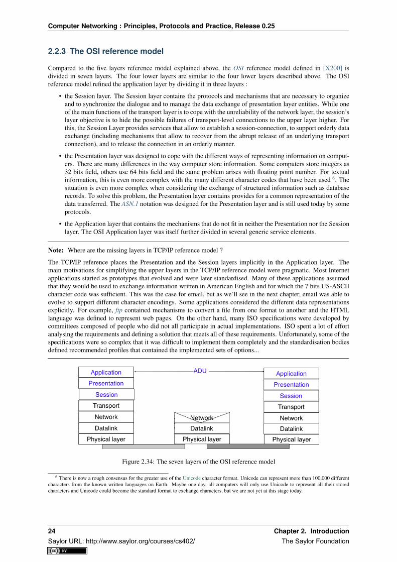
2.2.3 The OSI reference model
Compared to the five layers reference model explained above, the OSI reference model defined in [X200] isdivided in seven layers. The four lower layers are similar to the four lower layers described above. The OSIreference model refined the application layer by dividing it in three layers :
• the Session layer. The Session layer contains the protocols and mechanisms that are necessary to organizeand to synchronize the dialogue and to manage the data exchange of presentation layer entities. While oneof the main functions of the transport layer is to cope with the unreliability of the network layer, the session’slayer objective is to hide the possible failures of transport-level connections to the upper layer higher. Forthis, the Session Layer provides services that allow to establish a session-connection, to support orderly dataexchange (including mechanisms that allow to recover from the abrupt release of an underlying transportconnection), and to release the connection in an orderly manner.
• the Presentation layer was designed to cope with the different ways of representing information on comput-ers. There are many differences in the way computer store information. Some computers store integers as32 bits field, others use 64 bits field and the same problem arises with floating point number. For textualinformation, this is even more complex with the many different character codes that have been used 6. Thesituation is even more complex when considering the exchange of structured information such as databaserecords. To solve this problem, the Presentation layer contains provides for a common representation of thedata transferred. The ASN.1 notation was designed for the Presentation layer and is still used today by someprotocols.
• the Application layer that contains the mechanisms that do not fit in neither the Presentation nor the Sessionlayer. The OSI Application layer was itself further divided in several generic service elements.
Note: Where are the missing layers in TCP/IP reference model ?
The TCP/IP reference places the Presentation and the Session layers implicitly in the Application layer. Themain motivations for simplifying the upper layers in the TCP/IP reference model were pragmatic. Most Internetapplications started as prototypes that evolved and were later standardised. Many of these applications assumedthat they would be used to exchange information written in American English and for which the 7 bits US-ASCIIcharacter code was sufficient. This was the case for email, but as we’ll see in the next chapter, email was able toevolve to support different character encodings. Some applications considered the different data representationsexplicitly. For example, ftp contained mechanisms to convert a file from one format to another and the HTMLlanguage was defined to represent web pages. On the other hand, many ISO specifications were developed bycommittees composed of people who did not all participate in actual implementations. ISO spent a lot of effortanalysing the requirements and defining a solution that meets all of these requirements. Unfortunately, some of thespecifications were so complex that it was difficult to implement them completely and the standardisation bodiesdefined recommended profiles that contained the implemented sets of options...
Figure 2.34: The seven layers of the OSI reference model
6 There is now a rough consensus for the greater use of the Unicode character format. Unicode can represent more than 100,000 differentcharacters from the known written languages on Earth. Maybe one day, all computers will only use Unicode to represent all their storedcharacters and Unicode could become the standard format to exchange characters, but we are not yet at this stage today.
24 Chapter 2. IntroductionSaylor URL: http://www.saylor.org/courses/cs402/ The Saylor Foundation

Computer Networking : Principles, Protocols and Practice, Release 0.25
2.3 Organisation of the book
This document is organised according to the TCP/IP reference model and follows a top-down approach. Mostof the classical networking textbooks chose a bottom-up approach, i.e. they first explained all the electrical andoptical details of the physical layer then moved to the datalink layer. This approach worked well during the infancyof computer networks and until the late 1990s. At that time, most students were not users of computer networksand it was useful to explain computer networks by building the corresponding protocols from the simplest, in thephysical layer, up to the application layer. Today, all students are active users of Internet applications, and startingto learn computer networking by looking at bits is not very motivating. Starting from [KuroseRoss09], manytextbooks and teachers have chosen a top-down approach. This approach starts from applications such as emailand web that students already know and explores the different layers, starting from the application layer. Thisapproach works quite well with today’s students. The traditional bottom-up approach could in fact be consideredas an engineering approach as it starts from the simple network that allows the exchange of bits, and explains howto combine different protocols and mechanisms to build the most complex applications. The top-down approachcould on the other hand be considered as a scientific approach. Like biologists, it starts from an existing (man-built) system and explores it layer by layer.
Besides the top-down versus bottom-up organisation, computer networking books can either aim at having anin-depth coverage of a small number of topics, or at having a limited coverage of a wide range of topics. Coveringa wide range of topics is interesting for introductory courses or for students who do not need a detailed knowledgeof computer networks. It allows the students to learn a little about everything and then start from this basicknowledge later if they need to understand computer networking in more detail. This books chose to cover, indetail, a smaller number of topics than other textbooks. This is motivated by the fact that computer networks oftenneed to be pushed to their limits. Understanding the details of the main networking protocols is important to beable to fully grasp how a network behaves or extend it to provide innovative services 7.
The book is organised as follows: We first describe the application layer in chapter The application Layer. Giventhe large number of Internet-based applications, it is of course impossible to cover them all in detail. Instead wefocus on three types of Internet-based applications. We first study the Domain Name System (DNS) and thenexplain some of the protocols involved in the exchange of electronic mail. The discussion of the application layerends with a description of the key protocols of the world wide web.
All these applications rely on the transport layer that is explained in chapter The transport layer. This is a keylayer in today’s networks as it contains all the mechanisms necessary to provide a reliable delivery of data over anunreliable network. We cover the transport layer by first developing a simple reliable transport layer protocol andthen explain the details of the TCP and UDP protocols used in TCP/IP networks.
After the transport layer, we analyse the network layer in chapter The network layer. This is also a very importantlayer as it is responsible for the delivery of packets from any source to any destination through intermediate routers.In the network layer, we describe the two possible organisations of the network layer and the routing protocolsbased on link-state and distance vectors. Then we explain in detail the IPv4, IPv6, RIP, OSPF and BGP protocolsthat are actually used in today’s Internet.
The last chapter of the book is devoted to the datalink layer. In chapter The datalink layer and the Local AreaNetworks, we begin by explaining the principles of the datalink layers on point-to-point links. Then, we focus onthe Local Area Networks. We first describe the Medium Access Control algorithms that allow multiple hosts toshare one transmission medium. We consider both opportunistic and deterministic techniques. We then explain indetail two types of LANs that are important from a deployment viewpoint today : Ethernet and WiFi.
7 A popular quote says, the devil is in the details. This quote reflects very well the operation of many network protocols, where the changeof a single bit may have huge consequences. In computer networks, understanding all the details is sometimes necessary.
2.3. Organisation of the book 25Saylor URL: http://www.saylor.org/courses/cs402/ The Saylor Foundation

Computer Networking : Principles, Protocols and Practice, Release 0.25
26 Chapter 2. IntroductionSaylor URL: http://www.saylor.org/courses/cs402/ The Saylor Foundation

CHAPTER 3
The application Layer
The Application Layer is the most important and most visible layer in computer networks. Applications reside inthis layer and human users interact via those applications through the network.
In this chapter, we first briefly describe the main principles of the application layer and focus on the two mostimportant application models : the client-server and the peer-to-peer models. Then, we review in detail twofamilies of protocols that have proved to be very useful in the Internet : electronic mail and the protocols thatallow access to information on the world wide web. We also describe the Domain Name System that allowshumans to use user-friendly names while the hosts use 32 bits or 128 bits long IP addresses.
3.1 Principles
The are two important models used to organise a networked application. The first and oldest model is the client-server model. In this model, a server provides services to clients that exchange information with it. This model ishighly asymmetrical : clients send requests and servers perform actions and return responses. It is illustrated inthe figure below.
Figure 3.1: The client-server model
The client-server model was the first model to be used to develop networked applications. This model comesnaturally from the mainframes and minicomputers that were the only networked computers used until the 1980s.A minicomputer is a multi-user system that is used by tens or more users at the same time. Each user interactswith the minicomputer by using a terminal. Those terminals, were mainly a screen, a keyboard and a cable directlyconnected to the minicomputer.
There are various types of servers as well as various types of clients. A web server provides information inresponse to the query sent by its clients. A print server prints documents sent as queries by the client. Anemail server will forward towards their recipient the email messages sent as queries while a music server willdeliver the music requested by the client. From the viewpoint of the application developer, the client and theserver applications directly exchange messages (the horizontal arrows labelled Queries and Responses in theabove figure), but in practice these messages are exchanged thanks to the underlying layers (the vertical arrows inthe above figure). In this chapter, we focus on these horizontal exchanges of messages.
27Saylor URL: http://www.saylor.org/courses/cs402/ The Saylor Foundation

Computer Networking : Principles, Protocols and Practice, Release 0.25
Networked applications do not exchange random messages. In order to ensure that the server is able to understandthe queries sent by a client, and also that the client is able to understand the responses sent by the server, they mustboth agree on a set of syntactical and semantic rules. These rules define the format of the messages exchanged aswell as their ordering. This set of rules is called an application-level protocol.
An application-level protocol is similar to a structured conversation between humans. Assume that Alice wantsto know the current time but does not have a watch. If Bob passes close by, the following conversation could takeplace :
• Alice : Hello
• Bob : Hello
• Alice : What time is it ?
• Bob : 11:55
• Alice : Thank you
• Bob : You’re welcome
Such a conversation succeeds if both Alice and Bob speak the same language. If Alice meets Tchang who onlyspeaks Chinese, she won’t be able to ask him the current time. A conversation between humans can be morecomplex. For example, assume that Bob is a security guard whose duty is to only allow trusted secret agents toenter a meeting room. If all agents know a secret password, the conversation between Bob and Trudy could be asfollows :
• Bob : What is the secret password ?
• Trudy : 1234
• Bob : This is the correct password, you’re welcome
If Alice wants to enter the meeting room but does not know the password, her conversation could be as follows :
• Bob : What is the secret password ?
• Alice : 3.1415
• Bob : This is not the correct password.
Human conversations can be very formal, e.g. when soldiers communicate with their hierarchy, or informal suchas when friends discuss. Computers that communicate are more akin to soldiers and require well-defined rules toensure an successful exchange of information. There are two types of rules that define how information can beexchanged between computers :
• syntactical rules that precisely define the format of the messages that are exchanged. As computers onlyprocess bits, the syntactical rules specify how information is encoded as bit strings
• organisation of the information flow. For many applications, the flow of information must be structured andthere are precedence relationships between the different types of information. In the time example above,Alice must greet Bob before asking for the current time. Alice would not ask for the current time first andgreet Bob afterwards. Such precedence relationships exist in networked applications as well. For example,a server must receive a username and a valid password before accepting more complex commands from itsclients.
Let us first discuss the syntactical rules. We will later explain how the information flow can be organised byanalysing real networked applications.
Application-layer protocols exchange two types of messages. Some protocols such as those used to supportelectronic mail exchange messages expressed as strings or lines of characters. As the transport layer allows hoststo exchange bytes, they need to agree on a common representation of the characters. The first and simplest methodto encode characters is to use the ASCII table. RFC 20 provides the ASCII table that is used by many protocolson the Internet. For example, the table defines the following binary representations :
• A : 1000011b
• 0 : 0110000b
• z : 1111010b
28 Chapter 3. The application LayerSaylor URL: http://www.saylor.org/courses/cs402/ The Saylor Foundation

Computer Networking : Principles, Protocols and Practice, Release 0.25
• @ : 1000000b
• space : 0100000b
In addition, the ASCII table also defines several non-printable or control characters. These characters were de-signed to allow an application to control a printer or a terminal. These control characters include CR and LF, thatare used to terminate a line, and the Bell character which causes the terminal to emit a sound.
• carriage return (CR) : 0001101b
• line feed (LF) : 0001010b
• Bell: 0000111b
The ASCII characters are encoded as a seven bits field, but transmitted as an eight-bits byte whose high order bitis usually set to 0. Bytes are always transmitted starting from the high order or most significant bit.
Most applications exchange strings that are composed of fixed or variable numbers of characters. A commonsolution to define the character strings that are acceptable is to define them as a grammar using a Backus-NaurForm (BNF) such as the Augmented BNF defined in RFC 5234. A BNF is a set of production rules that generateall valid character strings. For example, consider a networked application that uses two commands, where theuser can supply a username and a password. The BNF for this application could be defined as shown in the figurebelow.
Figure 3.2: A simple BNF specification
The example above defines several terminals and two commands : usercommand and passwordcommand. TheALPHA terminal contains all letters in upper and lower case. In the ALPHA rule, %x41 corresponds to ASCIIcharacter code 41 in hexadecimal, i.e. capital A. The CR and LF terminals correspond to the carriage return andlinefeed control characters. The CRLF rule concatenates these two terminals to match the standard end of linetermination. The DIGIT terminal contains all digits. The SP terminal corresponds to the white space characters.The usercommand is composed of two strings separated by white space. In the ABNF rules that define themessages used by Internet applications, the commands are case-insensitive. The rule “user” corresponds to allpossible cases of the letters that compose the word between brackets, e.g. user, uSeR, USER, usER, ... A usernamecontains at least one letter and up to 8 letters. User names are case-sensitive as they are not defined as a stringbetween brackets. The password rule indicates that a password starts with a letter and can contain any number ofletters or digits. The white space and the control characters cannot appear in a password defined by the above rule.
Besides character strings, some applications also need to exchange 16 bits and 32 bits fields such as integers. Anaive solution would have been to send the 16- or 32-bits field as it is encoded in the host’s memory. Unfortunately,there are different methods to store 16- or 32-bits fields in memory. Some CPUs store the most significant byteof a 16-bits field in the first address of the field while others store the least significant byte at this location. Whennetworked applications running on different CPUs exchange 16 bits fields, there are two possibilities to transferthem over the transport service :
• send the most significant byte followed by the least significant byte
• send the least significant byte followed by the most significant byte
The first possibility was named big-endian in a note written by Cohen [Cohen1980] while the second was namedlittle-endian. Vendors of CPUs that used big-endian in memory insisted on using big-endian encoding in net-worked applications while vendors of CPUs that used little-endian recommended the opposite. Several studieswere written on the relative merits of each type of encoding, but the discussion became almost a religious issue[Cohen1980]. Eventually, the Internet chose the big-endian encoding, i.e. multi-byte fields are always transmit-ted by sending the most significant byte first, RFC 791 refers to this encoding as the network-byte order. Most
3.1. Principles 29Saylor URL: http://www.saylor.org/courses/cs402/ The Saylor Foundation

Computer Networking : Principles, Protocols and Practice, Release 0.25
libraries 1 used to write networked applications contain functions to convert multi-byte fields from memory to thenetwork byte order and vice versa.
Besides 16 and 32 bit words, some applications need to exchange data structures containing bit fields of variouslengths. For example, a message may be composed of a 16 bits field followed by eight, one bit flags, a 24 bitsfield and two 8 bits bytes. Internet protocol specifications will define such a message by using a representationsuch as the one below. In this representation, each line corresponds to 32 bits and the vertical lines are used todelineate fields. The numbers above the lines indicate the bit positions in the 32-bits word, with the high order bitat position 0.
Figure 3.3: Message format
The message mentioned above will be transmitted starting from the upper 32-bits word in network byte order. Thefirst field is encoded in 16 bits. It is followed by eight one bit flags (A-H), a 24 bits field whose high order byte isshown in the first line and the two low order bytes appear in the second line followed by two one byte fields. ThisASCII representation is frequently used when defining binary protocols. We will use it for all the binary protocolsthat are discussed in this book.
We will discuss several examples of application-level protocols in this chapter.
3.1.1 The peer-to-peer model
The peer-to-peer model emerged during the last ten years as another possible architecture for networked appli-cations. In the traditional client-server model, hosts act either as servers or as clients and a server serves a largenumber of clients. In the peer-to-peer model, all hosts act as both servers and clients and they play both roles.The peer-to-peer model has been used to develop various networked applications, ranging from Internet telephonyto file sharing or Internet-wide filesystems. A detailed description of peer-to-peer applications may be found in[BYL2008]. Surveys of peer-to-peer protocols and applications may be found in [AS2004] and [LCP2005].
3.1.2 The transport services
Networked applications are built on top of the transport service. As explained in the previous chapter, there aretwo main types of transport services :
• the connectionless or datagram service
• the connection-oriented or byte-stream service
The connectionless service allows applications to easily exchange messages or Service Data Units. On the Internet,this service is provided by the UDP protocol that will be explained in the next chapter. The connectionless transportservice on the Internet is unreliable, but is able to detect transmission errors. This implies that an application willnot receive an SDU that has been corrupted due to transmission errors.
The connectionless transport service allows networked application to exchange messages. Several networkedapplications may be running at the same time on a single host. Each of these applications must be able to exchangeSDUs with remote applications. To enable these exchanges of SDUs, each networked application running on ahost is identified by the following information :
• the host on which the application is running
• the port number on which the application listens for SDUs
1 For example, the htonl(3) (resp. ntohl(3)) function the standard C library converts a 32-bits unsigned integer from the byte orderused by the CPU to the network byte order (resp. from the network byte order to the CPU byte order). Similar functions exist in otherprogramming languages.
30 Chapter 3. The application LayerSaylor URL: http://www.saylor.org/courses/cs402/ The Saylor Foundation

Computer Networking : Principles, Protocols and Practice, Release 0.25
On the Internet, the port number is an integer and the host is identified by its network address. As we will see inchapter The network layer there are two types of Internet Addresses :
• IP version 4 addresses that are 32 bits wide
• IP version 6 addresses that are 128 bits wide
IPv4 addresses are usually represented by using a dotted decimal representation where each decimal numbercorresponds to one byte of the address, e.g. 203.0.113.56. IPv6 addresses are usually represented as a set ofhexadecimal numbers separated by semicolons, e.g. 2001:db8:3080:2:217:f2ff:fed6:65c0. Today, most Internethosts have one IPv4 address. A small fraction of them also have an IPv6 address. In the future, we can expect thatmore and more hosts will have IPv6 addresses and that some of them will not have an IPv4 address anymore. Ahost that only has an IPv4 address cannot communicate with a host having only an IPv6 address. The figure belowillustrates two that are using the datagram service provided by UDP on hosts that are using IPv4 addresses.
Figure 3.4: The connectionless or datagram service
The second transport service is the connection-oriented service. On the Internet, this service is often called thebyte-stream service as it creates a reliable byte stream between the two applications that are linked by a transportconnection. Like the datagram service, the networked applications that use the byte-stream service are identifiedby the host on which they run and a port number. These hosts can be identified by an IPv4 address, an IPv6address or a name. The figure below illustrates two applications that are using the byte-stream service providedby the TCP protocol on IPv6 hosts. The byte stream service provided by TCP is reliable and bidirectional.
Figure 3.5: The connection-oriented or byte-stream service
3.1. Principles 31Saylor URL: http://www.saylor.org/courses/cs402/ The Saylor Foundation

Computer Networking : Principles, Protocols and Practice, Release 0.25
3.2 Application-level protocols
Many protocols have been defined for networked applications. In this section, we describe some of the importantapplications that are used on the Internet. We first explain the Domain Name System (DNS) that enables hosts tobe identified by human-friendly names instead of the IPv4 or IPv6 addresses that are used by the network. Then,we describe the operation of electronic mail, one of the first killer applications on the global Internet, and theprotocols used on world wide web.
3.2.1 The Domain Name System
In the early days of the Internet, there were only a few number of hosts (mainly minicomputers) connected to thenetwork. The most popular applications were remote login and file transfer. By 1983, there were already fivehundred hosts attached to the Internet. Each of these hosts were identified by a unique IPv4 address. Forcinghuman users to remember the IPv4 addresses of the remote hosts that they want to use was not user-friendly.Human users prefer to remember names, and use them when needed. Using names as aliases for addresses is acommon technique in Computer Science. It simplifies the development of applications and allows the developerto ignore the low level details. For example, by using a programming language instead of writing machine code,a developer can write software without knowing whether the variables that it uses are stored in memory or insideregisters.
Because names are at a higher level than addresses, they allow (both in the example of programming above, and onthe Internet) to treat addresses as mere technical identifiers, which can change at will. Only the names are stable.On today’s Internet, where switching to another ISP means changing your IP addresses, the user-friendliness ofdomain names is less important (they are not often typed by users) but their stability remains a very important,may be their most important property.
The first solution that allowed applications to use names was the hosts.txt file. This file is similar to the symboltable found in compiled code. It contains the mapping between the name of each Internet host and its associated IPaddress 2. It was maintained by SRI International that coordinated the Network Information Center (NIC). Whena new host was connected to the network, the system administrator had to register its name and IP address at theNIC. The NIC updated the hosts.txt file on its server. All Internet hosts regularly retrieved the updated hosts.txtfile from the server maintained by SRI. This file was stored at a well-known location on each Internet host (seeRFC 952) and networked applications could use it to find the IP address corresponding to a name.
A hosts.txt file can be used when there are up to a few hundred hosts on the network. However, it is clearly notsuitable for a network containing thousands or millions of hosts. A key issue in a large network is to define asuitable naming scheme. The ARPANet initially used a flat naming space, i.e. each host was assigned a uniquename. To limit collisions between names, these names usually contained the name of the institution and a suffix toidentify the host inside the institution (a kind of poor man’s hierarchical naming scheme). On the ARPANet fewinstitutions had several hosts connected to the network.
However, the limitations of a flat naming scheme became clear before the end of the ARPANet and RFC 819proposed a hierarchical naming scheme. While RFC 819 discussed the possibility of organising the names as adirected graph, the Internet opted eventually for a tree structure capable of containing all names. In this tree, thetop-level domains are those that are directly attached to the root. The first top-level domain was .arpa 3. Thistop-level name was initially added as a suffix to the names of the hosts attached to the ARPANet and listed inthe hosts.txt file. In 1984, the .gov, .edu, .com, .mil and .org generic top-level domain names were added andRFC 1032 proposed the utilisation of the two letter ISO-3166 country codes as top-level domain names. SinceISO-3166 defines a two letter code for each country recognised by the United Nations, this allowed all countriesto automatically have a top-level domain. These domains include .be for Belgium, .fr for France, .us for the USA,.ie for Ireland or .tv for Tuvalu, a group of small islands in the Pacific and .tm for Turkmenistan. Today, the setof top-level domain-names is managed by the Internet Corporation for Assigned Names and Numbers (ICANN).Recently, ICANN added a dozen of generic top-level domains that are not related to a country and the .cat top-leveldomain has been registered for the Catalan language. There are ongoing discussions within ICANN to increasethe number of top-level domains.
2 The hosts.txt file is not maintained anymore. A historical snapshot retrieved on April 15th, 1984 is available fromhttp://ftp.univie.ac.at/netinfo/netinfo/hosts.txt
3 See http://www.donelan.com/dnstimeline.html for a time line of DNS related developments.
32 Chapter 3. The application LayerSaylor URL: http://www.saylor.org/courses/cs402/ The Saylor Foundation

Computer Networking : Principles, Protocols and Practice, Release 0.25
Each top-level domain is managed by an organisation that decides how sub-domain names can be registered. Mosttop-level domain names use a first-come first served system, and allow anyone to register domain names, butthere are some exceptions. For example, .gov is reserved for the US government, .int is reserved for internationalorganisations and names in the .ca are mainly reserved for companies or users who are present in Canada.
Figure 3.6: The tree of domain names
RFC 1035 recommended the following BNF for fully qualified domain names, to allow host names with a syntaxwhich works with all applications (the domain names themselves have a much richer syntax).
Figure 3.7: BNF of the fully qualified host names
This grammar specifies that a host name is an ordered list of labels separated by the dot (.) character. Each labelcan contain letters, numbers and the hyphen character (-) 4. Fully qualified domain names are read from left toright. The first label is a hostname or a domain name followed by the hierarchy of domains and ending with theroot implicitly at the right. The top-level domain name must be one of the registered TLDs 5. For example, in theabove figure, www.whitehouse.gov corresponds to a host named www inside the whitehouse domain that belongsto the gov top-level domain. info.ucl.ac.be corresponds to the info domain inside the ucl domain that is includedin the ac sub-domain of the be top-level domain.
This hierarchical naming scheme is a key component of the Domain Name System (DNS). The DNS is a dis-tributed database that contains mappings between fully qualified domain names and IP addresses. The DNS usesthe client-server model. The clients are hosts that need to retrieve the mapping for a given name. Each nameserverstores part of the distributed database and answers the queries sent by clients. There is at least one nameserver thatis responsible for each domain. In the figure below, domains are represented by circles and there are three hostsinside domain dom (h1, h2 and h3) and three hosts inside domain a.sdom1.dom. As shown in the figure below, asub-domain may contain both host names and sub-domains.
Figure 3.8: A simple tree of domain names
4 This specification evolved later to support domain names written by using other character sets than us-ASCII RFC 5890. This extensionis important to support languages other than English, but a detailed discussion is outside the scope of this document.
5 The official list of top-level domain names is maintained by :term:‘IANA at http://data.iana.org/TLD/tlds-alpha-by-domain.txt Additionalinformation about these domains may be found at http://en.wikipedia.org/wiki/List_of_Internet_top-level_domains
3.2. Application-level protocols 33Saylor URL: http://www.saylor.org/courses/cs402/ The Saylor Foundation

Computer Networking : Principles, Protocols and Practice, Release 0.25
A nameserver that is responsible for domain dom can directly answer the following queries :
• the IP address of any host residing directly inside domain dom (e.g. h2.dom in the figure above)
• the nameserver(s) that are responsible for any direct sub-domain of domain dom (i.e. sdom1.dom andsdom2.dom in the figure above, but not z.sdom1.dom)
To retrieve the mapping for host h2.dom, a client sends its query to the name server that is responsible for domain.dom. The name server directly answers the query. To retrieve a mapping for h3.a.sdom1.dom a DNS client firstsends a query to the name server that is responsible for the .dom domain. This nameserver returns the nameserverthat is responsible for the sdom1.dom domain. This nameserver can now be contacted to obtain the nameserverthat is responsible for the a.sdom1.dom domain. This nameserver can be contacted to retrieve the mapping for theh3.a.sdom1.dom name. Thanks to this organisation of the nameservers, it is possible for a DNS client to obtain themapping of any host inside the .dom domain or any of its subdomains. To ensure that any DNS client will be ableto resolve any fully qualified domain name, there are special nameservers that are responsible for the root of thedomain name hierarchy. These nameservers are called root nameserver. There are currently about a dozen rootnameservers 6.
Each root nameserver maintains the list 7 of all the nameservers that are responsible for each of the top-leveldomain names and their IP addresses 8. All root nameservers are synchronised and provide the same answers.By querying any of the root nameservers, a DNS client can obtain the nameserver that is responsible for anytop-level-domain name. From this nameserver, it is possible to resolve any domain name.
To be able to contact the root nameservers, each DNS client must know their IP addresses. This implies, thatDNS clients must maintain an up-to-date list of the IP addresses of the root nameservers 9. Without this list, itis impossible to contact the root nameservers. Forcing all Internet hosts to maintain the most recent version ofthis list would be difficult from an operational point of view. To solve this problem, the designers of the DNSintroduced a special type of DNS server : the DNS resolvers. A resolver is a server that provides the nameresolution service for a set of clients. A network usually contains a few resolvers. Each host in these networks isconfigured to send all its DNS queries via one of its local resolvers. These queries are called recursive queries asthe resolver must recurse through the hierarchy of nameservers to obtain the answer.
DNS resolvers have several advantages over letting each Internet host query directly nameservers. Firstly, regularInternet hosts do not need to maintain the up-to-date list of the IP addresses of the root servers. Secondly, regularInternet hosts do not need to send queries to nameservers all over the Internet. Furthermore, as a DNS resolverserves a large number of hosts, it can cache the received answers. This allows the resolver to quickly returnanswers for popular DNS queries and reduces the load on all DNS servers [JSBM2002].
The last component of the Domain Name System is the DNS protocol. The DNS protocol runs above both thedatagram service and the bytestream services. In practice, the datagram service is used when short queries andresponses are exchanged, and the bytestream service is used when longer responses are expected. In this section,we will only discuss the utilisation of the DNS protocol above the datagram service. This is the most frequentutilisation of the DNS.
DNS messages are composed of five parts that are named sections in RFC 1035. The first three sections aremandatory and the last two sections are optional. The first section of a DNS message is its Header. It containsinformation about the type of message and the content of the other sections. The second section contains theQuestion sent to the name server or resolver. The third section contains the Answer to the Question. When a clientsends a DNS query, the Answer section is empty. The fourth section, named Authority, contains information aboutthe servers that can provide an authoritative answer if required. The last section contains additional informationthat is supplied by the resolver or server but was not requested in the question.
The header of DNS messages is composed of 12 bytes and its structure is shown in the figure below.
The ID (identifier) is a 16-bits random value chosen by the client. When a client sends a question to a DNS server,it remembers the question and its identifier. When a server returns an answer, it returns in the ID field the identifier
6 There are currently 13 root servers. In practice, some of these root servers are themselves implemented as a set of distinct physicalservers. See http://www.root-servers.org/ for more information about the physical location of these servers.
7 A copy of the information maintained by each root nameserver is available at http://www.internic.net/zones/root.zone8 Until February 2008, the root DNS servers only had IPv4 addresses. IPv6 addresses were added to the root DNS servers slowly to
avoid creating problems as discussed in http://www.icann.org/en/committees/security/sac018.pdf In 2010, several DNS root servers are stillnot reachable by using IPv6.
9 The current list of the IP addresses of the root nameservers is maintained at http://www.internic.net/zones/named.root . These IP addressesare stable and root nameservers seldom change their IP addresses. DNS resolvers must however maintain an up-to-date copy of this file.
34 Chapter 3. The application LayerSaylor URL: http://www.saylor.org/courses/cs402/ The Saylor Foundation
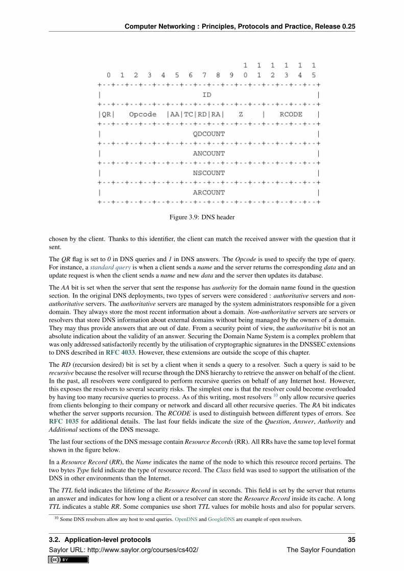
Computer Networking : Principles, Protocols and Practice, Release 0.25
Figure 3.9: DNS header
chosen by the client. Thanks to this identifier, the client can match the received answer with the question that itsent.
The QR flag is set to 0 in DNS queries and 1 in DNS answers. The Opcode is used to specify the type of query.For instance, a standard query is when a client sends a name and the server returns the corresponding data and anupdate request is when the client sends a name and new data and the server then updates its database.
The AA bit is set when the server that sent the response has authority for the domain name found in the questionsection. In the original DNS deployments, two types of servers were considered : authoritative servers and non-authoritative servers. The authoritative servers are managed by the system administrators responsible for a givendomain. They always store the most recent information about a domain. Non-authoritative servers are servers orresolvers that store DNS information about external domains without being managed by the owners of a domain.They may thus provide answers that are out of date. From a security point of view, the authoritative bit is not anabsolute indication about the validity of an answer. Securing the Domain Name System is a complex problem thatwas only addressed satisfactorily recently by the utilisation of cryptographic signatures in the DNSSEC extensionsto DNS described in RFC 4033. However, these extensions are outside the scope of this chapter.
The RD (recursion desired) bit is set by a client when it sends a query to a resolver. Such a query is said to berecursive because the resolver will recurse through the DNS hierarchy to retrieve the answer on behalf of the client.In the past, all resolvers were configured to perform recursive queries on behalf of any Internet host. However,this exposes the resolvers to several security risks. The simplest one is that the resolver could become overloadedby having too many recursive queries to process. As of this writing, most resolvers 10 only allow recursive queriesfrom clients belonging to their company or network and discard all other recursive queries. The RA bit indicateswhether the server supports recursion. The RCODE is used to distinguish between different types of errors. SeeRFC 1035 for additional details. The last four fields indicate the size of the Question, Answer, Authority andAdditional sections of the DNS message.
The last four sections of the DNS message contain Resource Records (RR). All RRs have the same top level formatshown in the figure below.
In a Resource Record (RR), the Name indicates the name of the node to which this resource record pertains. Thetwo bytes Type field indicate the type of resource record. The Class field was used to support the utilisation of theDNS in other environments than the Internet.
The TTL field indicates the lifetime of the Resource Record in seconds. This field is set by the server that returnsan answer and indicates for how long a client or a resolver can store the Resource Record inside its cache. A longTTL indicates a stable RR. Some companies use short TTL values for mobile hosts and also for popular servers.
10 Some DNS resolvers allow any host to send queries. OpenDNS and GoogleDNS are example of open resolvers.
3.2. Application-level protocols 35Saylor URL: http://www.saylor.org/courses/cs402/ The Saylor Foundation

Computer Networking : Principles, Protocols and Practice, Release 0.25
Figure 3.10: DNS Resource Records
For example, a web hosting company that wants to spread the load over a pool of hundred servers can configureits nameservers to return different answers to different clients. If each answer has a small TTL, the clients will beforced to send DNS queries regularly. The nameserver will reply to these queries by supplying the address of theless loaded server.
The RDLength field is the length of the RData field that contains the information of the type specified in the Typefield.
Several types of DNS RR are used in practice. The A type is used to encode the IPv4 address that corresponds tothe specified name. The AAAA type is used to encode the IPv6 address that corresponds to the specified name. ANS record contains the name of the DNS server that is responsible for a given domain. For example, a query forthe A record associated to the www.ietf.org name returns the following answer.
This answer contains several pieces of information. First, the name www.ietf.org is associated to IP address64.170.98.32. Second, the ietf.org domain is managed by six different nameservers. Three of these nameserversare reachable via IPv4 and IPv6. Two of them are not reachable via IPv6 and ns0.ietf.org is only reachablevia IPv6. A query for the AAAA record associated to www.ietf.org returns 2001:1890:1112:1::20 and the sameauthority and additional sections.
CNAME (or canonical names) are used to define aliases. For example www.example.com could be a CNAME forpc12.example.com that is the actual name of the server on which the web server for www.example.com runs.
Note: Reverse DNS and in-addr.arpa
The DNS is mainly used to find the IP address that correspond to a given name. However, it is sometimes usefulto obtain the name that corresponds to an IP address. This done by using the PTR (pointer) RR. The RData partof a PTR RR contains the name while the Name part of the RR contains the IP address encoded in the in-addr.arpadomain. IPv4 addresses are encoded in the in-addr.arpa by reversing the four digits that compose the dotteddecimal representation of the address. For example, consider IPv4 address 192.0.2.11. The hostname associatedto this address can be found by requesting the PTR RR that corresponds to 11.2.0.192.in-addr.arpa. A similarsolution is used to support IPv6 addresses, see RFC 3596.
36 Chapter 3. The application LayerSaylor URL: http://www.saylor.org/courses/cs402/ The Saylor Foundation

Computer Networking : Principles, Protocols and Practice, Release 0.25
Figure 3.11: Query for the A record of www.ietf.org
An important point to note regarding the Domain Name System is its extensibility. Thanks to the Type andRDLength fields, the format of the Resource Records can easily be extended. Furthermore, a DNS implementationthat receives a new Resource Record that it does not understand can ignore the record while still being able toprocess the other parts of the message. This allows, for example, a DNS server that only supports IPv4 to ignorethe IPv6 addresses listed in the DNS reply for www.ietf.org while still being able to correctly parse the ResourceRecords that it understands. This extensibility allowed the Domain Name System to evolve over the years whilestill preserving the backward compatibility with already deployed DNS implementations.
3.2.2 Electronic mail
Electronic mail, or email, is a very popular application in computer networks such as the Internet. Email appearedin the early 1970s and allows users to exchange text based messages. Initially, it was mainly used to exchangeshort messages, but over the years its usage has grown. It is now not only used to exchange small, but also longmessages that can be composed of several parts as we will see later.
Before looking at the details of Internet email, let us consider a simple scenario illustrated in the figure below,where Alice sends an email to Bob. Alice prepares her email by using an email clients and sends it to her emailserver. Alice’s email server extracts Bob’s address from the email and delivers the message to Bob’s server. Bobretrieves Alice’s message on his server and reads it by using his favourite email client or through his webmailinterface.
Figure 3.12: Simplified architecture of the Internet email
The email system that we consider in this book is composed of four components :
• a message format, that defines how valid email messages are encoded
• protocols, that allow hosts and servers to exchange email messages
3.2. Application-level protocols 37Saylor URL: http://www.saylor.org/courses/cs402/ The Saylor Foundation

Computer Networking : Principles, Protocols and Practice, Release 0.25
• client software, that allows users to easily create and read email messages
• software, that allows servers to efficiently exchange email messages
We will first discuss the format of email messages followed by the protocols that are used on today’s Internet toexchange and retrieve emails. Other email systems have been developed in the past [Bush1993] [Genilloud1990][GC2000], but today most email solutions have migrated to the Internet email. Information about the softwarethat is used to compose and deliver emails may be found on wikipedia among others, for both email clients andemail servers. More detailed information about the full Internet Mail Architecture may be found in RFC 5598.
Email messages, like postal mail, are composed of two parts :
• a header that plays the same role as the letterhead in regular mail. It contains metadata about the message.
• the body that contains the message itself.
Email messages are entirely composed of lines of ASCII characters. Each line can contain up to 998 charactersand is terminated by the CR and LF control characters RFC 5322. The lines that compose the header appearbefore the message body. An empty line, containing only the CR and LF characters, marks the end of the header.This is illustrated in the figure below.
Figure 3.13: The structure of email messages
The email header contains several lines that all begin with a keyword followed by a colon and additional informa-tion. The format of email messages and the different types of header lines are defined in RFC 5322. Two of theseheader lines are mandatory and must appear in all email messages :
• The sender address. This header line starts with From:. This contains the (optional) name of the senderfollowed by its email address between < and >. Email addresses are always composed of a usernamefollowed by the @ sign and a domain name.
• The date. This header line starts with Date:. RFC 5322 precisely defines the format used to encode a date.
Other header lines appear in most email messages. The Subject: header line allows the sender to indicate the topicdiscussed in the email. Three types of header lines can be used to specify the recipients of a message :
• the To: header line contains the email addresses of the primary recipients of the message 11 . Severaladdresses can be separated by using commas.
• the cc: header line is used by the sender to provide a list of email addresses that must receive a carbon copyof the message. Several addresses can be listed in this header line, separated by commas. All recipients ofthe email message receive the To: and cc: header lines.
• the bcc: header line is used by the sender to provide a list of comma separated email addresses that mustreceive a blind carbon copy of the message. The bcc: header line is not delivered to the recipients of theemail message.
A simple email message containing the From:, To:, Subject: and Date: header lines and two lines of body is shownbelow.
11 It could be surprising that the To: is not mandatory inside an email message. While most email messages will contain this header line anemail that does not contain a To: header line and that relies on the bcc: to specify the recipient is valid as well.
38 Chapter 3. The application LayerSaylor URL: http://www.saylor.org/courses/cs402/ The Saylor Foundation

Computer Networking : Principles, Protocols and Practice, Release 0.25
From: Bob Smith <[email protected]>To: Alice Doe <[email protected]>, Alice Smith <[email protected]>Subject: HelloDate: Mon, 8 Mar 2010 19:55:06 -0600
This is the "Hello world" of email messages.This is the second line of the body
Note the empty line after the Date: header line; this empty line contains only the CR and LF characters, and marksthe boundary between the header and the body of the message.
Several other optional header lines are defined in RFC 5322 and elsewhere 12. Furthermore, many email clientsand servers define their own header lines starting from X-. Several of the optional header lines defined in RFC5322 are worth being discussed here :
• the Message-Id: header line is used to associate a “unique” identifier to each email. Email identifiers areusually structured like string@domain where string is a unique character string or sequence number chosenby the sender of the email and domain the domain name of the sender. Since domain names are unique,a host can generate globally unique message identifiers concatenating a locally unique identifier with itsdomain name.
• the In-reply-to: is used when a message was created in reply to a previous message. In this case, the end ofthe In-reply-to: line contains the identifier of the original message.
• the Received: header line is used when an email message is processed by several servers before reaching itsdestination. Each intermediate email server adds a Received: header line. These header lines are useful todebug problems in delivering email messages.
The figure below shows the header lines of one email message. The message originated at a host namedwira.firstpr.com.au and was received by smtp3.sgsi.ucl.ac.be. The Received: lines have been wrapped for read-ability.
Received: from smtp3.sgsi.ucl.ac.be (Unknown [10.1.5.3])by mmp.sipr-dc.ucl.ac.be(Sun Java(tm) System Messaging Server 7u3-15.01 64bit (built Feb 12 2010))with ESMTP id <[email protected]>; Mon,08 Mar 2010 11:37:17 +0100 (CET)
Received: from mail.ietf.org (mail.ietf.org [64.170.98.32])by smtp3.sgsi.ucl.ac.be (Postfix) with ESMTP id B92351C60D7; Mon,08 Mar 2010 11:36:51 +0100 (CET)
Received: from [127.0.0.1] (localhost [127.0.0.1]) by core3.amsl.com (Postfix)with ESMTP id F066A3A68B9; Mon, 08 Mar 2010 02:36:38 -0800 (PST)
Received: from localhost (localhost [127.0.0.1]) by core3.amsl.com (Postfix)with ESMTP id A1E6C3A681B for <[email protected]>; Mon,08 Mar 2010 02:36:37 -0800 (PST)
Received: from mail.ietf.org ([64.170.98.32])by localhost (core3.amsl.com [127.0.0.1]) (amavisd-new, port 10024)with ESMTP id erw8ih2v8VQa for <[email protected]>; Mon,08 Mar 2010 02:36:36 -0800 (PST)
Received: from gair.firstpr.com.au (gair.firstpr.com.au [150.101.162.123])by core3.amsl.com (Postfix) with ESMTP id 03E893A67ED for <[email protected]>; Mon,08 Mar 2010 02:36:35 -0800 (PST)
Received: from [10.0.0.6] (wira.firstpr.com.au [10.0.0.6])by gair.firstpr.com.au (Postfix) with ESMTP id D0A49175B63; Mon,08 Mar 2010 21:36:37 +1100 (EST)
Date: Mon, 08 Mar 2010 21:36:38 +1100From: Robin Whittle <[email protected]>Subject: Re: [rrg] Recommendation and what happens nextIn-reply-to: <C7B9C21A.4FAB%[email protected]>To: RRG <[email protected]>Message-id: <[email protected]>
12 The list of all standard email header lines may be found at http://www.iana.org/assignments/message-headers/message-header-index.html
3.2. Application-level protocols 39Saylor URL: http://www.saylor.org/courses/cs402/ The Saylor Foundation

Computer Networking : Principles, Protocols and Practice, Release 0.25
Message content removed
Initially, email was used to exchange small messages of ASCII text between computer scientists. However, withthe growth of the Internet, supporting only ASCII text became a severe limitation for two reasons. First of all,non-English speakers wanted to write emails in their native language that often required more characters thanthose of the ASCII character table. Second, many users wanted to send other content than just ASCII text byemail such as binary files, images or sound.
To solve this problem, the IETF developed the Multipurpose Internet Mail Extensions (MIME). These extensionswere carefully designed to allow Internet email to carry non-ASCII characters and binary files without breakingthe email servers that were deployed at that time. This requirement for backward compatibility forced the MIMEdesigners to develop extensions to the existing email message format RFC 822 instead of defining a completelynew format that would have been better suited to support the new types of emails.
RFC 2045 defines three new types of header lines to support MIME :
• The MIME-Version: header indicates the version of the MIME specification that was used to encode theemail message. The current version of MIME is 1.0. Other versions of MIME may be defined in the future.Thanks to this header line, the software that processes email messages will be able to adapt to the MIMEversion used to encode the message. Messages that do not contain this header are supposed to be formattedaccording to the original RFC 822 specification.
• The Content-Type: header line indicates the type of data that is carried inside the message (see below)
• The Content-Transfer-Encoding: header line is used to specify how the message has been encoded. WhenMIME was designed, some email servers were only able to process messages containing characters encodedusing the 7 bits ASCII character set. MIME allows the utilisation of other character encodings.
Inside the email header, the Content-Type: header line indicates how the MIME email message is structured. RFC2046 defines the utilisation of this header line. The two most common structures for MIME messages are :
• Content-Type: multipart/mixed. This header line indicates that the MIME message contains several inde-pendent parts. For example, such a message may contain a part in plain text and a binary file.
• Content-Type: multipart/alternative. This header line indicates that the MIME message contains severalrepresentations of the same information. For example, a multipart/alternative message may contain both aplain text and an HTML version of the same text.
To support these two types of MIME messages, the recipient of a message must be able to extract the differentparts from the message. In RFC 822, an empty line was used to separate the header lines from the body. Using anempty line to separate the different parts of an email body would be difficult as the body of email messages oftencontains one or more empty lines. Another possible option would be to define a special line, e.g. *-LAST_LINE-*to mark the boundary between two parts of a MIME message. Unfortunately, this is not possible as some emailsmay contain this string in their body (e.g. emails sent to students to explain the format of MIME messages). Tosolve this problem, the Content-Type: header line contains a second parameter that specifies the string that hasbeen used by the sender of the MIME message to delineate the different parts. In practice, this string is oftenchosen randomly by the mail client.
The email message below, copied from RFC 2046 shows a MIME message containing two parts that are both inplain text and encoded using the ASCII character set. The string simple boundary is defined in the Content-Type:header as the marker for the boundary between two successive parts. Another example of MIME messages maybe found in RFC 2046.
Date: Mon, 20 Sep 1999 16:33:16 +0200From: Nathaniel Borenstein <[email protected]>To: Ned Freed <[email protected]>Subject: TestMIME-Version: 1.0Content-Type: multipart/mixed; boundary="simple boundary"
preamble, to be ignored
--simple boundaryContent-Type: text/plain; charset=us-ascii
40 Chapter 3. The application LayerSaylor URL: http://www.saylor.org/courses/cs402/ The Saylor Foundation

Computer Networking : Principles, Protocols and Practice, Release 0.25
First part
--simple boundaryContent-Type: text/plain; charset=us-ascii
Second part--simple boundary
The Content-Type: header can also be used inside a MIME part. In this case, it indicates the type of data placedin this part. Each data type is specified as a type followed by a subtype. A detailed description may be found inRFC 2046. Some of the most popular Content-Type: header lines are :
• text. The message part contains information in textual format. There are several subtypes : text/plain forregular ASCII text, text/html defined in RFC 2854 for documents in HTML format or the text/enrichedformat defined in RFC 1896. The Content-Type: header line may contain a second parameter that specifiesthe character set used to encode the text. charset=us-ascii is the standard ASCII character table. Otherfrequent character sets include charset=UTF8 or charset=iso-8859-1. The list of standard character sets ismaintained by IANA
• image. The message part contains a binary representation of an image. The subtype indicates the format ofthe image such as gif, jpg or png.
• audio. The message part contains an audio clip. The subtype indicates the format of the audio clip like wavor mp3
• video. The message part contains a video clip. The subtype indicates the format of the video clip like avi ormp4
• application. The message part contains binary information that was produced by the particular applicationlisted as the subtype. Email clients use the subtype to launch the application that is able to decode thereceived binary information.
Note: From ASCII to Unicode
The first computers used different techniques to represent characters in memory and on disk. During the 1960s,computers began to exchange information via tape or telephone lines. Unfortunately, each vendor had its ownproprietary character set and exchanging data between computers from different vendors was often difficult. The7 bits ASCII character table RFC 20 set was adopted by several vendors and by many Internet protocols. However,ASCII became a problem with the internationalisation of the Internet and the desire of more and more users to usecharacter sets that support their own written language. A first attempt at solving this problem was the definitionof the ISO-8859 character sets by ISO. This family of standards specified various character sets that allowed therepresentation of many European written languages by using 8 bits characters. Unfortunately, an 8-bits characterset is not sufficient to support some widely used languages, such as those used in Asian countries. Fortunately, atthe end of the 1980s, several computer scientists proposed to develop a standard that supports all written languagesused on Earth today. The Unicode standard [Unicode] has now been adopted by most computer and softwarevendors. For example, Java uses Unicode natively to manipulate characters, Python can handle both ASCII andUnicode characters. Internet applications are slowly moving towards complete support for the Unicode charactersets, but moving from ASCII to Unicode is an important change that can have a huge impact on current deployedimplementations. See for example, the work to completely internationalise email RFC 4952 and domain namesRFC 5890.
The last MIME header line is Content-Transfer-Encoding:. This header line is used after the Content-Type: headerline, within a message part, and specifies how the message part has been encoded. The default encoding is to use7 bits ASCII. The most frequent encodings are quoted-printable and Base64. Both support encoding a sequenceof bytes into a set of ASCII lines that can be safely transmitted by email servers. quoted-printable is defined inRFC 2045. We briefly describe base64 which is defined in RFC 2045 and RFC 4648.
Base64 divides the sequence of bytes to be encoded into groups of three bytes (with the last group possibly beingpartially filled). Each group of three bytes is then divided into four six-bit fields and each six bit field is encodedas a character from the table below.
3.2. Application-level protocols 41Saylor URL: http://www.saylor.org/courses/cs402/ The Saylor Foundation

Computer Networking : Principles, Protocols and Practice, Release 0.25
Value Encoding Value Encoding Value Encoding Value Encoding0 A 17 R 34 i 51 z1 B 18 S 35 j 52 02 C 19 T 36 k 53 13 D 20 U 37 l 54 24 E 21 V 38 m 55 35 F 22 W 39 n 56 46 G 23 X 40 o 57 57 H 24 Y 41 p 58 68 I 25 Z 42 q 59 79 J 26 a 43 r 60 810 K 27 b 44 s 61 911 L 28 c 45 t 62 +12 M 29 d 46 u 63 /13 N 30 e 47 v14 O 31 f 48 w15 P 32 g 49 x16 Q 33 h 50 y
The example below, from RFC 4648, illustrates the Base64 encoding.
Input data 0x14fb9c03d97e8-bit 00010100 11111011 10011100 00000011 11011001 011111106-bit 000101 001111 101110 011100 000000 111101 100101 111110Decimal 5 15 46 28 0 61 37 62Encoding F P u c A 9 l +
The last point to be discussed about base64 is what happens when the length of the sequence of bytes to beencoded is not a multiple of three. In this case, the last group of bytes may contain one or two bytes instead ofthree. Base64 reserves the = character as a padding character. This character is used twice when the last groupcontains two bytes and once when it contains one byte as illustrated by the two examples below.
Input data 0x148-bit 000101006-bit 000101 000000Decimal 5 0Encoding F A = =
Input data 0x14b98-bit 00010100 111110116-bit 000101 001111 101100Decimal 5 15 44Encoding F P s =
Now that we have explained the format of the email messages, we can discuss how these messages can be ex-changed through the Internet. The figure below illustrates the protocols that are used when Alice sends an emailmessage to Bob. Alice prepares her email with an email client or on a webmail interface. To send her email toBob, Alice‘s client will use the Simple Mail Transfer Protocol (SMTP) to deliver her message to her SMTP server.Alice‘s email client is configured with the name of the default SMTP server for her domain. There is usually atleast one SMTP server per domain. To deliver the message, Alice‘s SMTP server must find the SMTP server thatcontains Bob‘s mailbox. This can be done by using the Mail eXchange (MX) records of the DNS. A set of MXrecords can be associated to each domain. Each MX record contains a numerical preference and the fully qualifieddomain name of a SMTP server that is able to deliver email messages destined to all valid email addresses of thisdomain. The DNS can return several MX records for a given domain. In this case, the server with the lowestpreference is used first. If this server is not reachable, the second most preferred server is used etc. Bob‘s SMTPserver will store the message sent by Alice until Bob retrieves it using a webmail interface or protocols such as thePost Office Protocol (POP) or the Internet Message Access Protocol (IMAP).
42 Chapter 3. The application LayerSaylor URL: http://www.saylor.org/courses/cs402/ The Saylor Foundation

Computer Networking : Principles, Protocols and Practice, Release 0.25
Figure 3.14: Email delivery protocols
The Simple Mail Transfer Protocol
The Simple Mail Transfer Protocol (SMTP) defined in RFC 5321 is a client-server protocol. The SMTP specifi-cation distinguishes between five types of processes involved in the delivery of email messages. Email messagesare composed on a Mail User Agent (MUA). The MUA is usually either an email client or a webmail. The MUAsends the email message to a Mail Submission Agent (MSA). The MSA processes the received email and forwardsit to the Mail Transmission Agent (MTA). The MTA is responsible for the transmission of the email, directly orvia intermediate MTAs to the MTA of the destination domain. This destination MTA will then forward the mes-sage to the Mail Delivery Agent (MDA) where it will be accessed by the recipient’s MUA. SMTP is used for theinteractions between MUA and MSA 13, MSA-MTA and MTA-MTA.
SMTP is a text-based protocol like many other application-layer protocols on the Internet. It relies on the byte-stream service. Servers listen on port 25. Clients send commands that are each composed of one line of ASCIItext terminated by CR+LF. Servers reply by sending ASCII lines that contain a three digit numerical error/successcode and optional comments.
The SMTP protocol, like most text-based protocols, is specified as a BNF. The full BNF is defined in RFC 5321.The main SMTP commands are defined by the BNF rules shown in the figure below.
Figure 3.15: BNF specification of the SMTP commands
In this BNF, atext corresponds to printable ASCII characters. This BNF rule is defined in RFC 5322. The fivemain commands are EHLO, MAIL FROM:, RCPT TO:, DATA and QUIT 14. Postmaster is the alias of the systemadministrator who is responsible for a given domain or SMTP server. All domains must have a Postmaster alias.
The SMTP responses are defined by the BNF shown in the figure below.
Figure 3.16: BNF specification of the SMTP responses
SMTP servers use structured reply codes containing three digits and an optional comment. The first digit of
13 During the last years, many Internet Service Providers, campus and enterprise networks have deployed SMTP extensions RFC 4954 ontheir MSAs. These extensions force the MUAs to be authenticated before the MSA accepts an email message from the MUA.
14 The first versions of SMTP used HELO as the first command sent by a client to a SMTP server. When SMTP was extended to supportnewer features such as 8 bits characters, it was necessary to allow a server to recognise whether it was interacting with a client that supportedthe extensions or not. EHLO became mandatory with the publication of RFC 2821.
3.2. Application-level protocols 43Saylor URL: http://www.saylor.org/courses/cs402/ The Saylor Foundation

Computer Networking : Principles, Protocols and Practice, Release 0.25
the reply code indicates whether the command was successful or not. A reply code of 2xy indicates that thecommand has been accepted. A reply code of 3xy indicates that the command has been accepted, but additionalinformation from the client is expected. A reply code of 4xy indicates a transient negative reply. This means thatfor some reason, which is indicated by either the other digits or the comment, the command cannot be processedimmediately, but there is some hope that the problem will only be transient. This is basically telling the client totry the same command again later. In contrast, a reply code of 5xy indicates a permanent failure or error. In thiscase, it is useless for the client to retry the same command later. Other application layer protocols such as FTPRFC 959 or HTTP RFC 2616 use a similar structure for their reply codes. Additional details about the other replycodes may be found in RFC 5321.
Examples of SMTP reply codes include the following :
500 Syntax error, command unrecognized501 Syntax error in parameters or arguments502 Command not implemented503 Bad sequence of commands220 <domain> Service ready221 <domain> Service closing transmission channel421 <domain> Service not available, closing transmission channel250 Requested mail action okay, completed450 Requested mail action not taken: mailbox unavailable452 Requested action not taken: insufficient system storage550 Requested action not taken: mailbox unavailable354 Start mail input; end with <CRLF>.<CRLF>
The first four reply codes correspond to errors in the commands sent by the client. The fourth reply code wouldbe sent by the server when the client sends commands in an incorrect order (e.g. the client tries to send an emailbefore providing the destination address of the message). Reply code 220 is used by the server as the first messagewhen it agrees to interact with the client. Reply code 221 is sent by the server before closing the underlyingtransport connection. Reply code 421 is returned when there is a problem (e.g. lack of memory/disk resources)that prevents the server from accepting the transport connection. Reply code 250 is the standard positive reply thatindicates the success of the previous command. Reply codes 450 and 452 indicate that the destination mailboxis temporarily unavailable, for various reasons, while reply code 550 indicates that the mailbox does not exist orcannot be used for policy reasons. Reply code 354 indicates that the client can start transmitting its email message.
The transfer of an email message is performed in three phases. During the first phase, the client opens a transportconnection with the server. Once the connection has been established, the client and the server exchange greetingsmessages (EHLO command). Most servers insist on receiving valid greeting messages and some of them drop theunderlying transport connection if they do not receive a valid greeting. Once the greetings have been exchanged,the email transfer phase can start. During this phase, the client transfers one or more email messages by indicatingthe email address of the sender (MAIL FROM: command), the email address of the recipient (RCPT TO: command)followed by the headers and the body of the email message (DATA command). Once the client has finished sendingall its queued email messages to the SMTP server, it terminates the SMTP association (QUIT command).
A successful transfer of an email message is shown below
S: 220 smtp.example.com ESMTP MTA informationC: EHLO mta.example.orgS: 250 Hello mta.example.org, glad to meet youC: MAIL FROM:<[email protected]>S: 250 OkC: RCPT TO:<[email protected]>S: 250 OkC: DATAS: 354 End data with <CR><LF>.<CR><LF>C: From: "Alice Doe" <[email protected]>C: To: Bob Smith <[email protected]>C: Date: Mon, 9 Mar 2010 18:22:32 +0100C: Subject: HelloC:C: Hello BobC: This is a small message containing 4 lines of text.C: Best regards,
44 Chapter 3. The application LayerSaylor URL: http://www.saylor.org/courses/cs402/ The Saylor Foundation

Computer Networking : Principles, Protocols and Practice, Release 0.25
C: AliceC: .S: 250 Ok: queued as 12345C: QUITS: 221 Bye
In the example above, the MTA running on mta.example.org opens a TCP connection to the SMTP server on hostsmtp.example.com. The lines prefixed with S: (resp. C:) are the responses sent by the server (resp. the commandssent by the client). The server sends its greetings as soon as the TCP connection has been established. The clientthen sends the EHLO command with its fully qualified domain name. The server replies with reply-code 250 andsends its greetings. The SMTP association can now be used to exchange an email.
To send an email, the client must first provide the address of the recipient with RCPT TO:. Then it uses the MAILFROM: with the address of the sender. Both the recipient and the sender are accepted by the server. The clientcan now issue the DATA command to start the transfer of the email message. After having received the 354 replycode, the client sends the headers and the body of its email message. The client indicates the end of the messageby sending a line containing only the . (dot) character 15. The server confirms that the email message has beenqueued for delivery or transmission with a reply code of 250. The client issues the QUIT command to close thesession and the server confirms with reply-code 221, before closing the TCP connection.
Note: Open SMTP relays and spam
Since its creation in 1971, email has been a very useful tool that is used by many users to exchange lots ofinformation. In the early days, all SMTP servers were open and anyone could use them to forward emails towardstheir final destination. Unfortunately, over the years, some unscrupulous users have found ways to use email formarketing purposes or to send malware. The first documented abuse of email for marketing purposes occurred in1978 when a marketer who worked for a computer vendor sent a marketing email to many ARPANET users. Atthat time, the ARPANET could only be used for research purposes and this was an abuse of the acceptable usepolicy. Unfortunately, given the extremely low cost of sending emails, the problem of unsolicited emails has notstopped. Unsolicited emails are now called spam and a study carried out by ENISA in 2009 reveals that 95% ofemail was spam and this number seems to continue to grow. This places a burden on the email infrastructure ofInternet Service Providers and large companies that need to process many useless messages.
Given the amount of spam messages, SMTP servers are no longer open RFC 5068. Several extensions to SMTPhave been developed in recent years to deal with this problem. For example, the SMTP authentication schemedefined in RFC 4954 can be used by an SMTP server to authenticate a client. Several techniques have also beenproposed to allow SMTP servers to authenticate the messages sent by their users RFC 4870 RFC 4871 .
The Post Office Protocol
When the first versions of SMTP were designed, the Internet was composed of minicomputers that were used byan entire university department or research lab. These minicomputers were used by many users at the same time.Email was mainly used to send messages from a user on a given host to another user on a remote host. At thattime, SMTP was the only protocol involved in the delivery of the emails as all hosts attached to the network wererunning an SMTP server. On such hosts, an email destined to local users was delivered by placing the email in aspecial directory or file owned by the user. However, the introduction of personal computers in the 1980s, changedthis environment. Initially, users of these personal computers used applications such as telnet to open a remotesession on the local minicomputer to read their email. This was not user-friendly. A better solution appearedwith the development of user friendly email client applications on personal computers. Several protocols weredesigned to allow these client applications to retrieve the email messages destined to a user from his/her server.Two of these protocols became popular and are still used today. The Post Office Protocol (POP), defined in RFC1939, is the simplest one. It allows a client to download all the messages destined to a given user from his/heremail server. We describe POP briefly in this section. The second protocol is the Internet Message Access Protocol(IMAP), defined in RFC 3501. IMAP is more powerful, but also more complex than POP. IMAP was designed toallow client applications to efficiently access in real-time to messages stored in various folders on servers. IMAP
15 This implies that a valid email message cannot contain a line with one dot followed by CR and LF. If a user types such a line in an email,his email client will automatically add a space character before or after the dot when sending the message over SMTP.
3.2. Application-level protocols 45Saylor URL: http://www.saylor.org/courses/cs402/ The Saylor Foundation

Computer Networking : Principles, Protocols and Practice, Release 0.25
assumes that all the messages of a given user are stored on a server and provides the functions that are necessaryto search, download, delete or filter messages.
POP is another example of a simple line-based protocol. POP runs above the bytestream service. A POP serverusually listens to port 110. A POP session is composed of three parts : an authorisation phase during whichthe server verifies the client’s credential, a transaction phase during which the client downloads messages and anupdate phase that concludes the session. The client sends commands and the server replies are prefixed by +OKto indicate a successful command or by -ERR to indicate errors.
When a client opens a transport connection with the POP server, the latter sends as banner an ASCII-line startingwith +OK. The POP session is at that time in the authorisation phase. In this phase, the client can send itsusername (resp. password) with the USER (resp. PASS) command. The server replies with +OK if the username(resp. password) is valid and -ERR otherwise.
Once the username and password have been validated, the POP session enters in the transaction phase. In thisphase, the client can issue several commands. The STAT command is used to retrieve the status of the server.Upon reception of this command, the server replies with a line that contains +OK followed by the number ofmessages in the mailbox and the total size of the mailbox in bytes. The RETR command, followed by a space andan integer, is used to retrieve the nth message of the mailbox. The DELE command is used to mark for deletionthe nth message of the mailbox.
Once the client has retrieved and possibly deleted the emails contained in the mailbox, it must issue the QUITcommand. This command terminates the POP session and allows the server to delete all the messages that havebeen marked for deletion by using the DELE command.
The figure below provides a simple POP session. All lines prefixed with C: (resp. S:) are sent by the client (resp.server).
S: +OK POP3 server readyC: USER aliceS: +OKC PASS 12345passS: +OK alice’s maildrop has 2 messages (620 octets)C: STATS: +OK 2 620C: LISTS: +OK 2 messages (620 octets)S: 1 120S: 2 500S: .C: RETR 1S: +OK 120 octetsS: <the POP3 server sends message 1>S: .C: DELE 1S: +OK message 1 deletedC: QUITS: +OK POP3 server signing off (1 message left)
In this example, a POP client contacts a POP server on behalf of the user named alice. Note that in this example,Alice’s password is sent in clear by the client. This implies that if someone is able to capture the packets sent byAlice, he will know Alice’s password 16. Then Alice’s client issues the STAT command to know the number ofmessages that are stored in her mailbox. It then retrieves and deletes the first message of the mailbox.
3.2.3 The HyperText Transfer Protocol
In the early days of the Internet was mainly used for remote terminal access with telnet, email and file transfer.The default file transfer protocol, FTP, defined in RFC 959 was widely used and FTP clients and servers are stillincluded in most operating systems.
16
RFC 1939 defines the APOP authentication scheme that is not vulnerable to such attacks.
46 Chapter 3. The application LayerSaylor URL: http://www.saylor.org/courses/cs402/ The Saylor Foundation

Computer Networking : Principles, Protocols and Practice, Release 0.25
Many FTP clients offer a user interface similar to a Unix shell and allow the client to browse the file system onthe server and to send and retrieve files. FTP servers can be configured in two modes :
• authenticated : in this mode, the ftp server only accepts users with a valid user name and password. Onceauthenticated, they can access the files and directories according to their permissions
• anonymous : in this mode, clients supply the anonymous userid and their email address as password. Theseclients are granted access to a special zone of the file system that only contains public files.
ftp was very popular in the 1990s and early 2000s, but today it has mostly been superseded by more recentprotocols. Authenticated access to files is mainly done by using the Secure Shell (ssh) protocol defined in RFC4251 and supported by clients such as scp or sftp. Nowadays, anonymous access is mainly provided by webprotocols.
In the late 1980s, high energy physicists working at CERN had to efficiently exchange documents about theirongoing and planned experiments. Tim Berners-Lee evaluated several of the documents sharing techniques thatwere available at that time [B1989]. As none of the existing solutions met CERN’s requirements, they choose todevelop a completely new document sharing system. This system was initially called the mesh, but was quicklyrenamed the world wide web. The starting point for the world wide web are hypertext documents. An hypertextdocument is a document that contains references (hyperlinks) to other documents that the reader can immediatelyaccess. Hypertext was not invented for the world wide web. The idea of hypertext documents was proposed in1945 [Bush1945] and the first experiments were done during the 1960s [Nelson1965] [Myers1998] . Compared tothe hypertext documents that were used in the late 1980s, the main innovation introduced by the world wide webwas to allow hyperlinks to reference documents stored on remote machines.
Figure 3.17: World-wide web clients and servers
A document sharing system such as the world wide web is composed of three important parts.
1. A standardised addressing scheme that allows unambiguous identification of documents
2. A standard document format : the HyperText Markup Language
3. A standardised protocol that facilitates efficient retrieval of documents stored on a server
Note: Open standards and open implementations
Open standards have, and are still playing a key role in the success of the world wide web as we know it to-day. Without open standards, the world wide web would never have reached its current size. In addition to openstandards, another important factor for the success of the web was the availability of open and efficient imple-mentations of these standards. When CERN started to work on the web, their objective was to build a runningsystem that could be used by physicists. They developed open-source implementations of the first web servers andweb clients. These open-source implementations were powerful and could be used as is, by institutions willing to
3.2. Application-level protocols 47Saylor URL: http://www.saylor.org/courses/cs402/ The Saylor Foundation

Computer Networking : Principles, Protocols and Practice, Release 0.25
share information on the web. They were also extended by other developers who contributed to new features. Forexample, NCSA added support for images in their Mosaic browser that was eventually used to create NetscapeCommunications.
The first components of the world wide web are the Uniform Resource Identifiers (URI), defined in RFC 3986. AURI is a character string that unambiguously identifies a resource on the world wide web. Here is a subset of theBNF for URIs
URI = scheme ":" "//" authority path [ "?" query ] [ "#" fragment ]scheme = ALPHA *( ALPHA / DIGIT / "+" / "-" / "." )authority = [ userinfo "@" ] host [ ":" port ]query = *( pchar / "/" / "?" )fragment = *( pchar / "/" / "?" )pchar = unreserved / pct-encoded / sub-delims / ":" / "@"query = *( pchar / "/" / "?" )fragment = *( pchar / "/" / "?" )pct-encoded = "%" HEXDIG HEXDIGunreserved = ALPHA / DIGIT / "-" / "." / "_" / "~"reserved = gen-delims / sub-delimsgen-delims = ":" / "/" / "?" / "#" / "[" / "]" / "@"sub-delims = "!" / "$" / "&" / "’" / "(" / ")" / "*" / "+" / "," / ";" / "="
The first component of a URI is its scheme. A scheme can be seen as a selector, indicating the meaning of thefields after it. In practice, the scheme often identifies the application-layer protocol that must be used by the clientto retrieve the document, but it is not always the case. Some schemes do not imply a protocol at all and somedo not indicate a retrievable document 17. The most frequent scheme is http that will be described later. A URIscheme can be defined for almost any application layer protocol [#furilist]_. The characters ‘: and // follow thescheme of any URI.
The second part of the URI is the authority. With retrievable URI, this includes the DNS name or the IP addressof the server where the document can be retrieved using the protocol specified via the scheme. This name canbe preceded by some information about the user (e.g. a user name) who is requesting the information. Earlierdefinitions of the URI allowed the specification of a user name and a password before the @ character ( RFC1738), but this is now deprecated as placing a password inside a URI is insecure. The host name can be followedby the semicolon character and a port number. A default port number is defined for some protocols and the portnumber should only be included in the URI if a non-default port number is used (for other protocols, techniqueslike service DNS records are used).
The third part of the URI is the path to the document. This path is structured as filenames on a Unix host (butit does not imply that the files are indeed stored this way on the server). If the path is not specified, the serverwill return a default document. The last two optional parts of the URI are used to provide a query and indicate aspecific part (e.g. a section in an article) of the requested document. Sample URIs are shown below.
http://tools.ietf.org/html/rfc3986.htmlmailto:[email protected]?subject=current-issuehttp://docs.python.org/library/basehttpserver.html?highlight=http#BaseHTTPServer.BaseHTTPRequestHandlertelnet://[2001:6a8:3080:3::2]:80/ftp://cnn.example.com&[email protected]/top_story.htm
The first URI corresponds to a document named rfc3986.html that is stored on the server named tools.ietf.org andcan be accessed by using the http protocol on its default port. The second URI corresponds to an email message,with subject current-issue, that will be sent to user infobot in domain example.com. The mailto: URI scheme isdefined in RFC 6068. The third URI references the portion BaseHTTPServer.BaseHTTPRequestHandler of thedocument basehttpserver.html that is stored in the library directory on server docs.python.org. This document canbe retrieved by using the http protocol. The query highlight=http is associated to this URI. The fourth example is aserver that operates the telnet protocol, uses IPv6 address 2001:6a8:3080:3::2 and is reachable on port 80. The lastURI is somewhat special. Most users will assume that it corresponds to a document stored on the cnn.example.com
17 An example of a non-retrievable URI is urn:isbn:0-380-81593-1 which is an unique identifier for a book, through the urn scheme(see RFC 3187). Of course, any URI can be make retrievable via a dedicated server or a new protocol but this one has no explicit proto-col. Same thing for the scheme tag (see RFC 4151), often used in Web syndication (see RFC 4287 about the Atom syndication format).Even when the scheme is retrievable (for instance with http‘), it is often used only as an identifier, not as a way to get a resource. Seehttp://norman.walsh.name/2006/07/25/namesAndAddresses for a good explanation.
48 Chapter 3. The application LayerSaylor URL: http://www.saylor.org/courses/cs402/ The Saylor Foundation

Computer Networking : Principles, Protocols and Practice, Release 0.25
server. However, to parse this URI, it is important to remember that the @ character is used to separate the username from the host name in the authorisation part of a URI. This implies that the URI points to a document namedtop_story.htm on host having IPv4 address 10.0.0.1. The document will be retrieved by using the ftp protocol withthe user name set to cnn.example.com&story=breaking_news.
The second component of the word wide web is the HyperText Markup Language (HTML). HTML defines theformat of the documents that are exchanged on the web. The first version of HTML was derived from the StandardGeneralized Markup Language (SGML) that was standardised in 1986 by ISO. SGML was designed to allowlarge project documents in industries such as government, law or aerospace to be shared efficiently in a machine-readable manner. These industries require documents to remain readable and editable for tens of years and insistedon a standardised format supported by multiple vendors. Today, SGML is no longer widely used beyond specificapplications, but its descendants including HTML and XML are now widespread.
A markup language is a structured way of adding annotations about the formatting of the document within thedocument itself. Example markup languages include troff, which is used to write the Unix man pages or Latex.HTML uses markers to annotate text and a document is composed of HTML elements. Each element is usuallycomposed of three items: a start tag that potentially includes some specific attributes, some text (often includingother elements), and an end tag. A HTML tag is a keyword enclosed in angle brackets. The generic form of aHTML element is
<tag>Some text to be displayed</tag>
More complex HTML elements can also include optional attributes in the start tag
<tag attribute1="value1" attribute2="value2">some text to be displayed</tag>
The HTML document shown below is composed of two parts : a header, delineated by the <head> and </head>markers, and a body (between the <body> and </body> markers). In the example below, the header only containsa title, but other types of information can be included in the header. The body contains an image, some text and alist with three hyperlinks. The image is included in the web page by indicating its URI between brackets inside the<img src=”...”> marker. The image can, of course, reside on any server and the client will automatically downloadit when rendering the web page. The <h1>...</h1> marker is used to specify the first level of headings. The <ul>marker indicates an unnumbered list while the <li> marker indicates a list item. The <a href=”URI”>text</a>indicates a hyperlink. The text will be underlined in the rendered web page and the client will fetch the specifiedURI when the user clicks on the link.
Figure 3.18: A simple HTML page
Additional details about the various extensions to HTML may be found in the official specifications maintainedby W3C.
The third component of the world wide web is the HyperText Transport Protocol (HTTP). HTTP is a text-basedprotocol, in which the client sends a request and the server returns a response. HTTP runs above the bytestreamservice and HTTP servers listen by default on port 80. The design of HTTP has largely been inspired by theInternet email protocols. Each HTTP request contains three parts :
• a method , that indicates the type of request, a URI, and the version of the HTTP protocol used by the client
3.2. Application-level protocols 49Saylor URL: http://www.saylor.org/courses/cs402/ The Saylor Foundation

Computer Networking : Principles, Protocols and Practice, Release 0.25
• a header , that is used by the client to specify optional parameters for the request. An empty line is used tomark the end of the header
• an optional MIME document attached to the request
The response sent by the server also contains three parts :
• a status line , that indicates whether the request was successful or not
• a header , that contains additional information about the response. The response header ends with an emptyline.
• a MIME document
Figure 3.19: HTTP requests and responses
Several types of method can be used in HTTP requests. The three most important ones are :
• the GET method is the most popular one. It is used to retrieve a document from a server. TheGET method is encoded as GET followed by the path of the URI of the requested document andthe version of HTTP used by the client. For example, to retrieve the http://www.w3.org/MarkUp/URI, a client must open a TCP on port 80 with host www.w3.org and send a HTTP requestcontaining the following line
GET /MarkUp/ HTTP/1.0
• – the HEAD method is a variant of the GET method that allows the retrieval of the headerlines for a given URI without retrieving the entire document. It can be used by a client toverify if a document exists, for instance.
• the POST method can be used by a client to send a document to a server. The sent document isattached to the HTTP request as a MIME document.
HTTP clients and servers can include many different HTTP headers in HTTP requests and responses. Each HTTPheader is encoded as a single ASCII-line terminated by CR and LF. Several of these headers are briefly describedbelow. A detailed discussion of all standard headers may be found in RFC 1945. The MIME headers can appearin both HTTP requests and HTTP responses.
• the Content-Length: header is the MIME header that indicates the length of the MIME document in bytes.
• the Content-Type: header is the MIME header that indicates the type of the attached MIME document.HTML pages use the text/html type.
• the Content-Encoding: header indicates how the MIME document has been encoded. For example, thisheader would be set to x-gzip for a document compressed using the gzip software.
RFC 1945 and RFC 2616 define headers that are specific to HTTP responses. These server headers include :
50 Chapter 3. The application LayerSaylor URL: http://www.saylor.org/courses/cs402/ The Saylor Foundation

Computer Networking : Principles, Protocols and Practice, Release 0.25
• the Server: header indicates the version of the web server that has generated the HTTP response. Someservers provide information about their software release and optional modules that they use. For securityreasons, some system administrators disable these headers to avoid revealing too much information abouttheir server to potential attackers.
• the Date: header indicates when the HTTP response has been produced by the server.
• the Last-Modified: header indicates the date and time of the last modification of the document attached tothe HTTP response.
Similarly, the following header lines can only appear inside HTTP requests sent by a client :
• the User-Agent: header provides information about the client that has generated the HTTP request. Someservers analyse this header line and return different headers and sometimes different documents for differentuser agents.
• the If-Modified-Since: header is followed by a date. It enables clients to cache in memory or on disk therecent or most frequently used documents. When a client needs to request a URI from a server, it first checkswhether the document is already in its cache. If it is, the client sends a HTTP request with the If-Modified-Since: header indicating the date of the cached document. The server will only return the document attachedto the HTTP response if it is newer than the version stored in the client’s cache.
• the Referrer: header is followed by a URI. It indicates the URI of the document that the client visited beforesending this HTTP request. Thanks to this header, the server can know the URI of the document containingthe hyperlink followed by the client, if any. This information is very useful to measure the impact ofadvertisements containing hyperlinks placed on websites.
• the Host: header contains the fully qualified domain name of the URI being requested.
Note: The importance of the Host: header line
The first version of HTTP did not include the Host: header line. This was a severe limitation for web host-ing companies. For example consider a web hosting company that wants to serve both web.example.com andwww.example.net on the same physical server. Both web sites contain a /index.html document. When a clientsends a request for either http://web.example.com/index.html or http://www.example.net/index.html, the HTTP 1.0request contains the following line :
GET /index.html HTTP/1.0
By parsing this line, a server cannot determine which index.html file is requested. Thanks to theHost: header line, the server knows whether the request is for http://web.example.com/index.html orhttp://www.dummy.net/index.html. Without the Host: header, this is impossible. The Host: header line allowedweb hosting companies to develop their business by supporting a large number of independent web servers on thesame physical server.
The status line of the HTTP response begins with the version of HTTP used by the server (usually HTTP/1.0defined in RFC 1945 or HTTP/1.1 defined in RFC 2616) followed by a three digit status code and additionalinformation in English. HTTP status codes have a similar structure as the reply codes used by SMTP.
• All status codes starting with digit 2 indicate a valid response. 200 Ok indicates that the HTTP request wassuccessfully processed by the server and that the response is valid.
• All status codes starting with digit 3 indicate that the requested document is no longer available on theserver. 301 Moved Permanently indicates that the requested document is no longer available on this server.A Location: header containing the new URI of the requested document is inserted in the HTTP response.304 Not Modified is used in response to an HTTP request containing the If-Modified-Since: header. Thisstatus line is used by the server if the document stored on the server is not more recent than the date indicatedin the If-Modified-Since: header.
• All status codes starting with digit 4 indicate that the server has detected an error in the HTTP request sentby the client. 400 Bad Request indicates a syntax error in the HTTP request. 404 Not Found indicates thatthe requested document does not exist on the server.
3.2. Application-level protocols 51Saylor URL: http://www.saylor.org/courses/cs402/ The Saylor Foundation

Computer Networking : Principles, Protocols and Practice, Release 0.25
• All status codes starting with digit 5 indicate an error on the server. 500 Internal Server Error indicates thatthe server could not process the request due to an error on the server itself.
In both the HTTP request and the HTTP response, the MIME document refers to a representation of the documentwith the MIME headers indicating the type of document and its size.
As an illustration of HTTP/1.0, the transcript below shows a HTTP request for http://www.ietf.org and the corre-sponding HTTP response. The HTTP request was sent using the curl command line tool. The User-Agent: headerline contains more information about this client software. There is no MIME document attached to this HTTPrequest, and it ends with a blank line.
GET / HTTP/1.0User-Agent: curl/7.19.4 (universal-apple-darwin10.0) libcurl/7.19.4 OpenSSL/0.9.8l zlib/1.2.3Host: www.ietf.org
The HTTP response indicates the version of the server software used with the modules included. The Last-Modified: header indicates that the requested document was modified about one week before the request. AHTML document (not shown) is attached to the response. Note the blank line between the header of the HTTPresponse and the attached MIME document. The Server: header line has been truncated in this output.
HTTP/1.1 200 OKDate: Mon, 15 Mar 2010 13:40:38 GMTServer: Apache/2.2.4 (Linux/SUSE) mod_ssl/2.2.4 OpenSSL/0.9.8e (truncated)Last-Modified: Tue, 09 Mar 2010 21:26:53 GMTContent-Length: 17019Content-Type: text/html
<!DOCTYPE HTML PUBLIC .../HTML>
HTTP was initially designed to share self-contained text documents. For this reason, and to ease the implemen-tation of clients and servers, the designers of HTTP chose to open a TCP connection for each HTTP request.This implies that a client must open one TCP connection for each URI that it wants to retrieve from a server asillustrated on the figure below. For a web page containing only text documents this was a reasonable design choiceas the client usually remains idle while the (human) user is reading the retrieved document.
Figure 3.20: HTTP 1.0 and the underlying TCP connection
However, as the web evolved to support richer documents containing images, opening a TCP connection for eachURI became a performance problem [Mogul1995]. Indeed, besides its HTML part, a web page may includedozens of images or more. Forcing the client to open a TCP connection for each component of a web pagehas two important drawbacks. First, the client and the server must exchange packets to open and close a TCPconnection as we will see later. This increases the network overhead and the total delay of completely retrievingall the components of a web page. Second, a large number of established TCP connections may be a performancebottleneck on servers.
This problem was solved by extending HTTP to support persistent TCP connections RFC 2616. A persistentconnection is a TCP connection over which a client may send several HTTP requests. This is illustrated in thefigure below.
52 Chapter 3. The application LayerSaylor URL: http://www.saylor.org/courses/cs402/ The Saylor Foundation

Computer Networking : Principles, Protocols and Practice, Release 0.25
Figure 3.21: HTTP 1.1 persistent connections
To allow the clients and servers to control the utilisation of these persistent TCP connections, HTTP 1.1 RFC2616 defines several new HTTP headers :
• The Connection: header is used with the Keep-Alive argument by the client to indicate that it expects theunderlying TCP connection to be persistent. When this header is used with the Close argument, it indicatesthat the entity that sent it will close the underlying TCP connection at the end of the HTTP response.
• The Keep-Alive: header is used by the server to inform the client about how it agrees to use the persistentconnection. A typical Keep-Alive: contains two parameters : the maximum number of requests that theserver agrees to serve on the underlying TCP connection and the timeout (in seconds) after which the serverwill close an idle connection
The example below shows the operation of HTTP/1.1 over a persistent TCP connection to retrieve three URIsstored on the same server. Once the connection has been established, the client sends its first request with theConnection: keep-alive header to request a persistent connection.
GET / HTTP/1.1Host: www.kame.netUser-Agent: Mozilla/5.0 (Macintosh; U; Intel Mac OS X 10_6_2; en-us)Connection: keep-alive
The server replies with the Connection: Keep-Alive header and indicates that it accepts a maximum of 100 HTTPrequests over this connection and that it will close the connection if it remains idle for 15 seconds.
HTTP/1.1 200 OKDate: Fri, 19 Mar 2010 09:23:37 GMTServer: Apache/2.0.63 (FreeBSD) PHP/5.2.12 with Suhosin-PatchKeep-Alive: timeout=15, max=100Connection: Keep-AliveContent-Length: 3462Content-Type: text/html
<html>... </html>
The client sends a second request for the style sheet of the retrieved web page.
GET /style.css HTTP/1.1Host: www.kame.netReferer: http://www.kame.net/User-Agent: Mozilla/5.0 (Macintosh; U; Intel Mac OS X 10_6_2; en-us)Connection: keep-alive
3.2. Application-level protocols 53Saylor URL: http://www.saylor.org/courses/cs402/ The Saylor Foundation

Computer Networking : Principles, Protocols and Practice, Release 0.25
The server replies with the requested style sheet and maintains the persistent connection. Note that the server onlyaccepts 99 remaining HTTP requests over this persistent connection.
HTTP/1.1 200 OKDate: Fri, 19 Mar 2010 09:23:37 GMTServer: Apache/2.0.63 (FreeBSD) PHP/5.2.12 with Suhosin-PatchLast-Modified: Mon, 10 Apr 2006 05:06:39 GMTContent-Length: 2235Keep-Alive: timeout=15, max=99Connection: Keep-AliveContent-Type: text/css
...
Then the client automatically requests the web server’s icon 18 , that could be displayed by the browser. This serverdoes not contain such URI and thus replies with a 404 HTTP status. However, the underlying TCP connection isnot closed immediately.
GET /favicon.ico HTTP/1.1Host: www.kame.netReferer: http://www.kame.net/User-Agent: Mozilla/5.0 (Macintosh; U; Intel Mac OS X 10_6_2; en-us)Connection: keep-alive
HTTP/1.1 404 Not FoundDate: Fri, 19 Mar 2010 09:23:40 GMTServer: Apache/2.0.63 (FreeBSD) PHP/5.2.12 with Suhosin-PatchContent-Length: 318Keep-Alive: timeout=15, max=98Connection: Keep-AliveContent-Type: text/html; charset=iso-8859-1
<!DOCTYPE HTML PUBLIC "-//IETF//DTD HTML 2.0//EN"> ...
As illustrated above, a client can send several HTTP requests over the same persistent TCP connection. However,it is important to note that all of these HTTP requests are considered to be independent by the server. Each HTTPrequest must be self-contained. This implies that each request must include all the header lines that are requiredby the server to understand the request. The independence of these requests is one of the important design choicesof HTTP. As a consequence of this design choice, when a server processes a HTTP request, it doesn’t’ use anyother information than what is contained in the request itself. This explains why the client adds its User-Agent:header in all of the HTTP requests it sends over the persistent TCP connection.
However, in practice, some servers want to provide content tuned for each user. For example, some serverscan provide information in several languages or other servers want to provide advertisements that are targeted todifferent types of users. To do this, servers need to maintain some information about the preferences of each userand use this information to produce content matching the user’s preferences. HTTP contains several mechanismsthat enable to solve this problem. We discuss three of them below.
A first solution is to force the users to be authenticated. This was the solution used by FTP to control the files thateach user could access. Initially, user names and passwords could be included inside URIs RFC 1738. However,placing passwords in the clear in a potentially publicly visible URI is completely insecure and this usage has nowbeen deprecated RFC 3986. HTTP supports several extension headers RFC 2617 that can be used by a serverto request the authentication of the client by providing his/her credentials. However, user names and passwordshave not been popular on web servers as they force human users to remember one user name and one passwordper server. Remembering a password is acceptable when a user needs to access protected content, but users willnot accept the need for a user name and password only to receive targeted advertisements from the web sites thatthey visit.
A second solution to allow servers to tune that content to the needs and capabilities of the user is to rely onthe different types of Accept-* HTTP headers. For example, the Accept-Language: can be used by the client to
18 Favorite icons are small icons that are used to represent web servers in the toolbar of Internet browsers. Microsoft added this featurein their browsers without taking into account the W3C standards. See http://www.w3.org/2005/10/howto-favicon for a discussion on how tocleanly support such favorite icons.
54 Chapter 3. The application LayerSaylor URL: http://www.saylor.org/courses/cs402/ The Saylor Foundation

Computer Networking : Principles, Protocols and Practice, Release 0.25
indicate its preferred languages. Unfortunately, in practice this header is usually set based on the default languageof the browser and it is not possible for a user to indicate the language it prefers to use by selecting options oneach visited web server.
The third, and widely adopted, solution are HTTP cookies. HTTP cookies were initially developed as a privateextension by Netscape. They are now part of the standard RFC 6265. In a nutshell, a cookie is a short string thatis chosen by a server to represent a given client. Two HTTP headers are used : Cookie: and Set-Cookie:. When aserver receives an HTTP request from a new client (i.e. an HTTP request that does not contain the Cookie: header),it generates a cookie for the client and includes it in the Set-Cookie: header of the returned HTTP response. TheSet-Cookie: header contains several additional parameters including the domain names for which the cookie isvalid. The client stores all received cookies on disk and every time it sends a HTTP request, it verifies whetherit already knows a cookie for this domain. If so, it attaches the Cookie: header to the HTTP request. This isillustrated in the figure below with HTTP 1.1, but cookies also work with HTTP 1.0.
Figure 3.22: HTTP cookies
Note: Privacy issues with HTTP cookies
The HTTP cookies introduced by Netscape are key for large e-commerce websites. However, they have alsoraised many discussions concerning their potential misuses. Consider ad.com, a company that delivers lots ofadvertisements on web sites. A web site that wishes to include ad.com‘s advertisements next to its content willadd links to ad.com inside its HTML pages. If ad.com is used by many web sites, ad.com could be able to track theinterests of all the users that visit its client websites and use this information to provide targeted advertisements.Privacy advocates have even sued online advertisement companies to force them to comply with the privacyregulations. More recent related technologies also raise privacy concerns
3.3 Writing simple networked applications
Networked applications were usually implemented by using the socket API. This API was designed when TCP/IPwas first implemented in the Unix BSD operating system [Sechrest] [LFJLMT], and has served as the model formany APIs between applications and the networking stack in an operating system. Although the socket API isvery popular, other APIs have also been developed. For example, the STREAMS API has been added to severalUnix System V variants [Rago1993]. The socket API is supported by most programming languages and severaltextbooks have been devoted to it. Users of the C language can consult [DC2009], [Stevens1998], [SFR2004] or[Kerrisk2010]. The Java implementation of the socket API is described in [CD2008] and in the Java tutorial. Inthis section, we will use the python implementation of the socket API to illustrate the key concepts. Additionalinformation about this API may be found in the socket section of the python documentation .
3.3. Writing simple networked applications 55Saylor URL: http://www.saylor.org/courses/cs402/ The Saylor Foundation
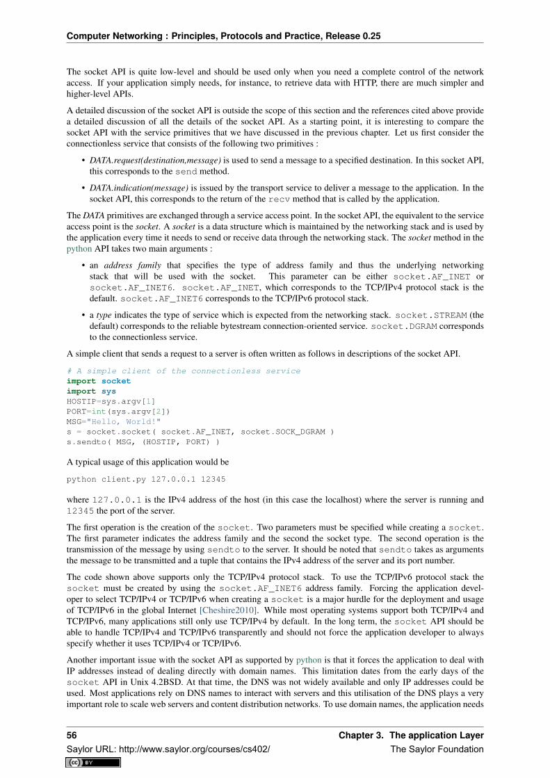
Computer Networking : Principles, Protocols and Practice, Release 0.25
The socket API is quite low-level and should be used only when you need a complete control of the networkaccess. If your application simply needs, for instance, to retrieve data with HTTP, there are much simpler andhigher-level APIs.
A detailed discussion of the socket API is outside the scope of this section and the references cited above providea detailed discussion of all the details of the socket API. As a starting point, it is interesting to compare thesocket API with the service primitives that we have discussed in the previous chapter. Let us first consider theconnectionless service that consists of the following two primitives :
• DATA.request(destination,message) is used to send a message to a specified destination. In this socket API,this corresponds to the send method.
• DATA.indication(message) is issued by the transport service to deliver a message to the application. In thesocket API, this corresponds to the return of the recv method that is called by the application.
The DATA primitives are exchanged through a service access point. In the socket API, the equivalent to the serviceaccess point is the socket. A socket is a data structure which is maintained by the networking stack and is used bythe application every time it needs to send or receive data through the networking stack. The socket method in thepython API takes two main arguments :
• an address family that specifies the type of address family and thus the underlying networkingstack that will be used with the socket. This parameter can be either socket.AF_INET orsocket.AF_INET6. socket.AF_INET, which corresponds to the TCP/IPv4 protocol stack is thedefault. socket.AF_INET6 corresponds to the TCP/IPv6 protocol stack.
• a type indicates the type of service which is expected from the networking stack. socket.STREAM (thedefault) corresponds to the reliable bytestream connection-oriented service. socket.DGRAM correspondsto the connectionless service.
A simple client that sends a request to a server is often written as follows in descriptions of the socket API.
# A simple client of the connectionless serviceimport socketimport sysHOSTIP=sys.argv[1]PORT=int(sys.argv[2])MSG="Hello, World!"s = socket.socket( socket.AF_INET, socket.SOCK_DGRAM )s.sendto( MSG, (HOSTIP, PORT) )
A typical usage of this application would be
python client.py 127.0.0.1 12345
where 127.0.0.1 is the IPv4 address of the host (in this case the localhost) where the server is running and12345 the port of the server.
The first operation is the creation of the socket. Two parameters must be specified while creating a socket.The first parameter indicates the address family and the second the socket type. The second operation is thetransmission of the message by using sendto to the server. It should be noted that sendto takes as argumentsthe message to be transmitted and a tuple that contains the IPv4 address of the server and its port number.
The code shown above supports only the TCP/IPv4 protocol stack. To use the TCP/IPv6 protocol stack thesocket must be created by using the socket.AF_INET6 address family. Forcing the application devel-oper to select TCP/IPv4 or TCP/IPv6 when creating a socket is a major hurdle for the deployment and usageof TCP/IPv6 in the global Internet [Cheshire2010]. While most operating systems support both TCP/IPv4 andTCP/IPv6, many applications still only use TCP/IPv4 by default. In the long term, the socket API should beable to handle TCP/IPv4 and TCP/IPv6 transparently and should not force the application developer to alwaysspecify whether it uses TCP/IPv4 or TCP/IPv6.
Another important issue with the socket API as supported by python is that it forces the application to deal withIP addresses instead of dealing directly with domain names. This limitation dates from the early days of thesocket API in Unix 4.2BSD. At that time, the DNS was not widely available and only IP addresses could beused. Most applications rely on DNS names to interact with servers and this utilisation of the DNS plays a veryimportant role to scale web servers and content distribution networks. To use domain names, the application needs
56 Chapter 3. The application LayerSaylor URL: http://www.saylor.org/courses/cs402/ The Saylor Foundation

Computer Networking : Principles, Protocols and Practice, Release 0.25
to perform the DNS resolution by using the getaddrinfo method. This method queries the DNS and buildsthe sockaddr data structure which is used by other methods of the socket API. In python, getaddrinfo takesseveral arguments :
• a name that is the domain name for which the DNS will be queried
• an optional port number which is the port number of the remote server
• an optional address family which indicates the address family used for the DNS request.socket.AF_INET (resp. socket.AF_INET6) indicates that an IPv4 (IPv6) address is expected. Fur-thermore, the python socket API allows an application to use socket.AF_UNSPEC to indicate that it isable to use either IPv4 or IPv6 addresses.
• an optional socket type which can be either socket.SOCK_DGRAM or socket.SOCK_STREAM
In today’s Internet hosts that are capable of supporting both IPv4 and IPv6, all applications should beable to handle both IPv4 and IPv6 addresses. When used with the socket.AF_UNSPEC parameter, thesocket.getaddrinfo method returns a list of tuples containing all the information to create a socket.
import socketsocket.getaddrinfo(’www.example.net’,80,socket.AF_UNSPEC,socket.SOCK_STREAM)[ (30, 1, 6, ’’, (’2001:db8:3080:3::2’, 80, 0, 0)),
(2, 1, 6, ’’, (’203.0.113.225’, 80))]
In the example above, socket.getaddrinfo returns two tuples. The first one corresponds to the sockaddrcontaining the IPv6 address of the remote server and the second corresponds to the IPv4 information. Due to somepeculiarities of IPv6 and IPv4, the format of the two tuples is not exactly the same, but the key information inboth cases are the network layer address (2001:db8:3080:3::2 and 203.0.113.225) and the port number(80). The other parameters are seldom used.
socket.getaddrinfo can be used to build a simple client that queries the DNS and contact the server byusing either IPv4 or IPv6 depending on the addresses returned by the socket.getaddrinfo method. Theclient below iterates over the list of addresses returned by the DNS and sends its request to the first destinationaddress for which it can create a socket. Other strategies are of course possible. For example, a host running inan IPv6 network might prefer to always use IPv6 when IPv6 is available 19. Another example is the happy eyeballsapproach which is being discussed within the IETF [WY2011]. For example, [WY2011] mentions that some webbrowsers try to use the first address returned by socket.getaddrinfo. If there is no answer within somesmall delay (e.g. 300 milliseconds), the second address is tried.
import socketimport sysHOSTNAME=sys.argv[1]PORT=int(sys.argv[2])MSG="Hello, World!"for a in socket.getaddrinfo(HOSTNAME, PORT, socket.AF_UNSPEC,socket.SOCK_DGRAM,0, socket.AI_PASSIVE) :
address_family,sock_type,protocol,canonicalname, sockaddr=atry:
s = socket.socket(address_family, sock_type)except socket.error:
s = Noneprint "Could not create socket"continue
if s is not None:s.sendto(MSG, sockaddr)break
Now that we have described the utilisation of the socket API to write a simple client using the connectionlesstransport service, let us have a closer look at the reliable byte stream transport service. As explained above, thisservice is invoked by creating a socket of type socket.SOCK_STREAM. Once a socket has been created, aclient will typically connect to the remote server, send some data, wait for an answer and eventually close theconnection. These operations are performed by calling the following methods :
19 Most operating systems today by default prefer to use IPv6 when the DNS returns both an IPv4 and an IPv6 address for a name. Seehttp://ipv6int.net/systems/ for more detailed information.
3.3. Writing simple networked applications 57Saylor URL: http://www.saylor.org/courses/cs402/ The Saylor Foundation

Computer Networking : Principles, Protocols and Practice, Release 0.25
• socket.connect : this method takes a sockaddr data structure, typically returned bysocket.getaddrinfo, as argument. It may fail and raise an exception if the remote server cannotbe reached.
• socket.send : this method takes a string as argument and returns the number of bytes that were actuallysent. The string will be transmitted as a sequence of consecutive bytes to the remote server. Applicationsare expected to check the value returned by this method and should resend the bytes that were not send.
• socket.recv : this method takes an integer as argument that indicates the size of the buffer that has beenallocated to receive the data. An important point to note about the utilisation of the socket.recv methodis that as it runs above a bytestream service, it may return any amount of bytes (up to the size of the bufferprovided by the application). The application needs to collect all the received data and there is no guaranteethat some data sent by the remote host by using a single call to the socket.send method will be receivedby the destination with a single call to the socket.recv method.
• socket.shutdown : this method is used to release the underlying connection. On some platforms, it ispossible to specify the direction of transfer to be released (e.g. socket.SHUT_WR to release the outgoingdirection or socket.SHUT_RDWR to release both directions).
• socket.close: this method is used to close the socket. It calls socket.shutdown if the underlyingconnection is still open.
With these methods, it is now possible to write a simple HTTP client. This client operates over both IPv6 and IPv4and writes the homepage of the remote server on the standard output. It also reports the number of socket.recvcalls that were used to retrieve the homepage 20 .
#!/usr/bin/python# A simple http client that retrieves the first page of a web site
import socket, sys
if len(sys.argv)!=3 and len(sys.argv)!=2:print "Usage : ",sys.argv[0]," hostname [port]"
hostname = sys.argv[1]if len(sys.argv)==3 :
port=int(sys.argv[2])else:
port = 80
READBUF=16384 # size of data read from web servers=None
for res in socket.getaddrinfo(hostname, port, socket.AF_UNSPEC, socket.SOCK_STREAM):af, socktype, proto, canonname, sa = res# create sockettry:
s = socket.socket(af, socktype, proto)except socket.error:
s = Nonecontinue
# connect to remote hosttry:
print "Trying "+sa[0]s.connect(sa)
except socket.error, msg:# socket faileds.close()s = Nonecontinue
if s :
20 Experiments with the client indicate that the number of socket.recv calls can vary at each run. There are various factors that influencethe number of such calls that are required to retrieve some information from a server. We’ll discuss some of them after having explained theoperation of the underlying transport protocol.
58 Chapter 3. The application LayerSaylor URL: http://www.saylor.org/courses/cs402/ The Saylor Foundation

Computer Networking : Principles, Protocols and Practice, Release 0.25
print "Connected to "+sa[0]s.send(’GET / HTTP/1.1\r\nHost:’+hostname+’\r\n\r\n’)finished=Falsecount=0while not finished:
data=s.recv(READBUF)count=count+1if len(data)!=0:
print repr(data)else:
finished=Trues.shutdown(socket.SHUT_WR)s.close()print "Data was received in ",count," recv calls"break
As mentioned above, the socket API is very low-level. This is the interface to the transport service. For a commonand simple task, like retrieving a document from the Web, there are much simpler solutions. For example, thepython standard library includes several high-level APIs to implementations of various application layer protocolsincluding HTTP. For example, the httplib module can be used to easily access documents via HTTP.
#!/usr/bin/python# A simple http client that retrieves the first page of a web site, using# the standard httplib library
import httplib, sys
if len(sys.argv)!=3 and len(sys.argv)!=2:print "Usage : ",sys.argv[0]," hostname [port]"sys.exit(1)
path = ’/’hostname = sys.argv[1]if len(sys.argv)==3 :port = int(sys.argv[2])
else:port = 80
conn = httplib.HTTPConnection(hostname, port)conn.request("GET", path)r = conn.getresponse()print "Response is %i (%s)" % (r.status, r.reason)print r.read()
Another module, urllib2 allows the programmer to directly use URLs. This is much more simpler than directlyusing sockets.
But simplicity is not the only advantage of using high-level libraries. They allow the programmer to manipulatehigher-level concepts ( e.g. I want the content pointed by this URL) but also include many features such astransparent support for the utilisation of TLS or IPv6.
The second type of applications that can be written by using the socket API are the servers. A server is typicallyruns forever waiting to process requests coming from remote clients. A server using the connectionless willtypically start with the creation of a socket with the socket.socket. This socket can be created above theTCP/IPv4 networking stack (socket.AF_INET) or the TCP/IPv6 networking stack (socket.AF_INET6),but not both by default. If a server is willing to use the two networking stacks, it must create two threads, one tohandle the TCP/IPv4 socket and the other to handle the TCP/IPv6 socket. It is unfortunately impossible to definea socket that can receive data from both networking stacks at the same time with the python socket API.
A server using the connectionless service will typically use two methods from the socket API in addition to thosethat we have already discussed.
• socket.bind is used to bind a socket to a port number and optionally an IP address. Most servers willbind their socket to all available interfaces on the servers, but there are some situations where the server
3.3. Writing simple networked applications 59Saylor URL: http://www.saylor.org/courses/cs402/ The Saylor Foundation

Computer Networking : Principles, Protocols and Practice, Release 0.25
may prefer to be bound only to specific IP addresses. For example, a server running on a smartphone mightwant to be bound to the IP address of the WiFi interface but not on the 3G interface that is more expensive.
• socket.recvfrom is used to receive data from the underlying networking stack. This method returnsboth the sender’s address and the received data.
The code below illustrates a very simple server running above the connectionless transport service that simplyprints on the standard output all the received messages. This server uses the TCP/IPv6 networking stack.
import socket, sys
PORT=int(sys.argv[1])BUFF_LEN=8192
s=socket.socket(socket.AF_INET6, socket.SOCK_DGRAM)s.bind((’’,PORT,0,0))while True:
data, addr = s.recvfrom( BUFF_LEN )if data=="STOP" :
print "Stopping server"sys.exit(0)
print "received from ", addr, " message:", data
A server that uses the reliable byte stream service can also be built above the socket API. Such a server startsby creating a socket that is bound to the port that has been chosen for the server. Then the server calls thesocket.listen method. This informs the underlying networking stack of the number of transport connectionattempts that can be queued in the underlying networking stack waiting to be accepted and processed by theserver. The server typically has a thread waiting on the socket.accept method. This method returns as soonas a connection attempt is received by the underlying stack. It returns a socket that is bound to the establishedconnection and the address of the remote host. With these methods, it is possible to write a very simple web serverthat always returns a 404 error to all GET requests and a 501 errors to all other requests.
# An extremely simple HTTP server
import socket, sys, time
# Server runs on all IP addresses by defaultHOST=’’# 8080 can be used without root priviledgesPORT=8080BUFLEN=8192 # buffer size
s = socket.socket(socket.AF_INET6, socket.SOCK_STREAM)try:
print "Starting HTTP server on port ", PORTs.bind((HOST,PORT,0,0))
except socket.error :print "Cannot bind to port :",PORTsys.exit(-1)
s.listen(10) # maximum 10 queued connections
while True:# a real server would be multithreaded and would catch exceptionsconn, addr = s.accept()print "Connection from ", addrdata=’’while not ’\n’ in data : # wait until first line has been received
data = data+conn.recv(BUFLEN)if data.startswith(’GET’):
# GET requestconn.send(’HTTP/1.0 404 Not Found\r\n’)# a real server should serve files
else:
60 Chapter 3. The application LayerSaylor URL: http://www.saylor.org/courses/cs402/ The Saylor Foundation

Computer Networking : Principles, Protocols and Practice, Release 0.25
# other type of HTTP requestconn.send(’HTTP/1.0 501 Not implemented\r\n’)
now = time.strftime("%a, %d %b %Y %H:%M:%S", time.localtime())conn.send(’Date: ’ + now +’\r\n’)conn.send(’Server: Dummy-HTTP-Server\r\n’)conn.send(’\r\n’)conn.shutdown(socket.SHUT_RDWR)conn.close()
This server is far from a production-quality web server. A real web server would use multiple threads and/ornon-blocking IO to process a large number of concurrent requests 21 . Furthermore, it would also need to handleall the errors that could happen while receiving data over a transport connection. These are outside the scopeof this section and additional information on more complex networked applications may be found elsewhere.For example, [RG2010] provides an in-depth discussion of the utilisation of the socket API with python while[SFR2004] remains an excellent source of information on the socket API in C.
3.4 Summary
In this chapter, we began by describing the client-server and peer-to-peer models. We then described, in detail,three important families of protocols in the application layer. The Internet identifies hosts by using 32 bits IPv4or 128 bits IPv6. However, using these addresses directly inside applications would be difficult for the humansthat use them. We have explained how the Domain Name System allows the mapping of names to correspondingaddresses. We have described both the DNS protocol that runs above UDP and the naming hierarchy. We havethen discussed one of the oldest applications on the Internet : electronic mail. We have described the format ofemail messages and described the SMTP protocol that is used to send email messages as well as the POP protocolthat is used by email recipients to retrieve their email messages from their server. Finally, we have explained theprotocols that are used in the world wide web and the HyperText Transfer Protocol in particular.
3.5 Exercises
This section contains several exercises and small challenges about the application layer protocols.
3.5.1 The Domain Name System
The Domain Name System (DNS) plays a key role in the Internet today as it allows applications to use fullyqualified domain names (FQDN) instead of IPv4 or IPv6 addresses. Many tools allow to perform queries throughDNS servers. For this exercise, we will use dig which is installed on most Unix systems.
A typical usage of dig is as follows
dig @server -t type fqdn
where
• server is the IP address or the name of a DNS server or resolver
• type is the type of DNS record that is requested by the query such as NS for a nameserver, A for an IPv4address, AAAA for an IPv6 address, MX for a mail relay, ...
• fqdn is the fully qualified domain name being queried
1. What are the IP addresses of the resolvers that the dig implementation you are using relies on 22 ?
21 There are many production quality web servers software available. apache is a very complex but widely used one. thttpd and lighttpd areless complex and their source code is probably easier to understand.
22 On a Linux machine, the Description section of the dig manpage tells you where dig finds the list of nameservers to query.
3.4. Summary 61Saylor URL: http://www.saylor.org/courses/cs402/ The Saylor Foundation
Computer Networking : Principles, Protocols and Practice, Release 0.25
2. What is the IP address that corresponds to inl.info.ucl.ac.be ? Which type of DNS query does dig send toobtain this information ?
3. Which type of DNS request do you need to send to obtain the nameservers that are responsible for a givendomain ?
4. What are the nameservers that are responsible for the be top-level domain ? Where are they located ? Is itpossible to use IPv6 to query them ?
5. When run without any parameter, dig queries one of the root DNS servers and retrieves the list of the thenames of all root DNS servers. For technical reasons, there are only 13 different root DNS servers. Thisinformation is also available as a text file from http://www.internic.net/zones/named.root What are the IPaddresses of all these servers. Can they be queried by using IPv6 23 ?
6. Assume now that you are residing in a network where there is no DNS resolver and that you need to startyour query from the DNS root.
• Use dig to send a query to one of these root servers to find the IP address of the DNS server(s) (NSrecord) responsible for the org top-level domain
• Use dig to send a query to one of these DNS servers to find the IP address of the DNS server(s) (NSrecord) responsible for root-servers.org‘
• Continue until you find the server responsible for www.root-servers.org
• What is the lifetime associated to this IP address ?
7. Perform the same analysis for a popular website such as www.google.com. What is the lifetime associatedto this IP address ? If you perform the same request several times, do you always receive the same answer? Can you explain why a lifetime is associated to the DNS replies ?
8. Use dig to find the mail relays used by the uclouvain.be and gmail.com domains. What is the TTL of theserecords (use the +ttlid option when using dig) ? Can you explain the preferences used by the MX records.You can find more information about the MX records in RFC 974
9. Use dig to query the IPv6 address (DNS record AAAA) of the following hosts
• www.sixxs.net
• www.google.com
• ipv6.google.com
10. When dig is run, the header section in its output indicates the id the DNS identifier used to send the query.Does your implementation of dig generates random identifiers ?
dig -t MX gmail.com
; <<>> DiG 9.4.3-P3 <<>> -t MX gmail.com;; global options: printcmd;; Got answer:;; ->>HEADER<<- opcode: QUERY, status: NOERROR, id: 25718
11. A DNS implementation such as dig and more importantly a name resolver such as bind or unbound, alwayschecks that the received DNS reply contains the same identifier as the DNS request that it sent. Why is thisso important ?
• Imagine an attacker who is able to send forged DNS replies to, for example, associatewww.bigbank.com to his own IP address. How could he attack a DNS implementation that
– sends DNS requests containing always the same identifier
– sends DNS requests containing identifiers that are incremented by one after each request
– sends DNS requests containing random identifiers
23 You may obtain additional information about the root DNS servers from http://www.root-servers.org
62 Chapter 3. The application LayerSaylor URL: http://www.saylor.org/courses/cs402/ The Saylor Foundation

Computer Networking : Principles, Protocols and Practice, Release 0.25
12. The DNS protocol can run over UDP and over TCP. Most DNS servers prefer to use UDP because itconsumes fewer resources on the server. However, TCP is useful when a large answer is expected or whena large answer must. You can force the utilisation of TCP by using dig +tcp. Use TCP and UDP to query aroot DNS server. Is it faster to receive an answer via TCP or via UDP ?
3.5.2 Internet email protocols
Many Internet protocols are ASCII-based protocols where the client sends requests as one line of ASCII textterminated by CRLF and the server replies with one of more lines of ASCII text. Using such ASCII messages hasseveral advantages compared to protocols that rely on binary encoded messages
• the messages exchanged by the client and the server can be easily understood by a developer or networkengineer by simply reading the messages
• it is often easy to write a small prototype that implements a part of the protocol
• it is possible to test a server manually by using telnet Telnet is a protocol that allows to obtain a terminal ona remote server. For this, telnet opens a TCP connection with the remote server on port 23. However, mosttelnet implementations allow the user to specify an alternate port as telnet hosts port When used with a portnumber as parameter, telnet opens a TCP connection to the remote host on the specified port. telnet canthus be used to test any server using an ASCII-based protocol on top of TCP. Note that if you need to stopa running telnet session, Ctrl-C will not work as it will be sent by telnet to the remote host over the TCPconnection. On many telnet implementations you can type Ctrl-] to freeze the TCP connection and returnto the telnet interface.
1. Assume that Alice sends an email from her [email protected] account to Bob who uses [email protected] protocols are involved in the transmission of this email ?
2. Same question when Alice sends an email to her friend Trudy, [email protected].
3. Before the advent of webmail and feature rich mailers, email was written and read by using command linetools on servers. Using your account on sirius.info.ucl.ac.be use the /bin/mail command line tool to sendan email to yourself on this host. This server stores local emails in the /var/mail directory with one file peruser. Check with /bin/more the content of your mail file and try to understand which lines have been addedby the server in the header of your email.
4. Use your preferred email tool to send an email message to yourself containing a single line of text. Mostemail tools have the ability to show the source of the message, use this function to look at the message thatyou sent and the message that you received. Can you find an explanation for all the lines that have beenadded to your single line email 24 ?
5. The first version of the SMTP protocol was defined in RFC 821. The current standard for SMTP is definedin RFC 5321 Considering only RFC 821 what are the main commands of the SMTP protocol 25 ?
6. When using SMTP, how do you recognise a positive reply from a negative one ?
7. A SMTP server is a daemon process that can fail due to a bug or lack of resources (e.g. memory). Networkadministrators often install tools 26 that regularly connect to their servers to check that they are operatingcorrectly. A simple solution is to open a TCP connection on port 25 to the SMTP server’s host 27 . If theconnection is established, this implies that there is a process listening. What is the reply sent by the SMTPserver when you type the following command ?
telnet cnp3.info.ucl.ac.be 25
24 Since RFC 821, SMTP has evolved a lot due notably to the growing usage of email and the need to protect the email system againstspammers. It is unlikely that you will be able to explain all the additional lines that you will find in email headers, but we’ll discuss themtogether.
25 A shorter description of the SMTP protocol may be found on wikipedia at http://en.wikipedia.org/wiki/Simple_Mail_Transfer_Protocol26 There are many monitoring tools available. nagios is a very popular open source monitoring system.27 Note that using telnet to connect to a remote host on port 25 may not work in all networks. Due to the spam problem, many ISP networks
do not allow their customers to use port TCP 25 directly and force them to use the ISP’s mail relay to forward their email. Thanks to this, ifa software sending spam has been installed on the PC of one of the ISP’s customers, this software will not be able to send a huge amount ofspam. If you connect to nostromo.info.ucl.ac.be from the fixed stations in INGI’s lab, you should not be blocked.
3.5. Exercises 63Saylor URL: http://www.saylor.org/courses/cs402/ The Saylor Foundation
Computer Networking : Principles, Protocols and Practice, Release 0.25
Warning : Do not try this on a random SMTP server. The exercises proposed in this section shouldonly be run on the SMTP server dedicated for these exercises : cnp3.info.ucl.ac.be. If you try themon a production SMTP server, the administrator of this server may become angry.
1. Continue the SMTP session that you started above by sending the greetings command (HELO followed bythe fully qualified domain name of your host) and terminate the session by sending the QUIT command.
2. The minimum SMTP session above allows to verify that the SMTP is running. However, this does notalways imply that mail can be delivered. For example, large SMTP servers often use a database to store allthe email addresses that they serve. To verify the correct operation of such a server, one possibility is touse the VRFY command. Open a SMTP session on the lab’s SMTP server (cnp3.info.ucl.ac.be) and use thiscommand to verify that your account is active.
3. Now that you know the basics of opening and closing an SMTP session, you can now send email manuallyby using the MAIL FROM:, RCPT TO: and DATA commands. Use these commands to manually send anemail to [email protected] . Do not forget to include the From:, To: and Subject: lines in yourheader.
1. By using SMTP, is it possible to send an email that contains exactly the following ASCII art ?......
1. Most email agents allow you to send email in carbon-copy (cc:) and also in blind-carbon-copy (bcc:) to arecipient. How does a SMTP server supports these two types of recipients ?
2. In the early days, email was read by using tools such as /bin/mail or more advanced text-based mail readerssuch as pine or elm . Today, emails are stored on dedicated servers and retrieved by using protocols suchas POP_ or IMAP. From the user’s viewpoint, can you list the advantages and drawbacks of these twoprotocols ?
3. The TCP protocol supports 65536 different ports numbers. Many of these port numbers have been reservedfor some applications. The official repository of the reserved port numbers is maintained by the InternetAssigned Numbers Authority (IANA) on http://www.iana.org/assignments/port-numbers 28. Using this in-formation, what is the default port number for the POP3 protocol ? Does it run on top of UDP or TCP?
4. The Post Office Protocol (POP) is a rather simple protocol described in RFC 1939. POP operates in threephases. The first phase is the authorization phase where the client provides a username and a password. Thesecond phase is the transaction phase where the client can retrieve emails. The last phase is the update phasewhere the client finalises the transaction. What are the main POP commands and their parameters ? Whena POP server returns an answer, how can you easily determine whether the answer is positive or negative ?
5. On smartphones, users often want to avoid downloading large emails over a slow wireless connection. Howcould a POP client only download emails that are smaller than 5 KBytes ?
6. Open a POP session with the lab’s POP server (nostromo.info.ucl.ac.be) by using the username and pass-word that you received. Verify that your username and password are accepted by the server.
7. The lab’s POP server contains a script that runs every minute and sends two email messages to your accountif your email folder is empty. Use POP to retrieve these two emails and provide the secret message to yourteaching assistant.
3.5.3 The HyperText Transfer Protocol
1. What are the main methods supported by the first version of the HyperText Transfer Protocol (HTTP)defined in RFC 1945 29 ? What are the main types of replies sent by a http server 30 ?
2. System administrators who are responsible for web servers often want to monitor these servers and checkthat they are running correctly. As a HTTP server uses TCP on port 80, the simplest solution is to open a
28 On Unix hosts, a subset of the port assignments is often placed in /etc/services29 See section 5 of RFC 194530 See section 6.1 of RFC 1945
64 Chapter 3. The application LayerSaylor URL: http://www.saylor.org/courses/cs402/ The Saylor Foundation

Computer Networking : Principles, Protocols and Practice, Release 0.25
TCP connection on port 80 and check that the TCP connection is accepted by the remote host. However, asHTTP is an ASCII-based protocol, it is also very easy to write a small script that downloads a web page onthe server and compares its content with the expected one. Use telnet to verify that a web server is runningon host rembrandt.info.ucl.ac.be 31
3. Instead of using telnet on port 80, it is also possible to use a command-line tool such as curl Use curl withthe –trace-ascii tracefile option to store in tracefile all the information exchanged by curl when accessingthe server.
• what is the version of HTTP used by curl ?
• can you explain the different headers placed by curl in the request ?
• can you explain the different headers found in the response ?
4. HTTP 1.1, specified in RFC 2616 forces the client to use the Host: in all its requests. HTTP 1.0 does notdefine the Host: header, by most implementations support it. By using telnet and curl retrieve the first pageof the http://totem.info.ucl.ac.be webserver by sending http requests with and without the Host: header.Explain the difference between the two 32 .
5. By using dig and curl , determine on which physical host the http://www.info.ucl.ac.be,http://inl.info.ucl.ac.be and http://totem.info.ucl.ac.be are hosted
6. Use curl with the –trace-ascii filename to retrieve http://www.google.com . Explain what a browser such asfirefox would do when retrieving this URL.
7. The headers sent in a HTTP request allow the client to provide additional information to the server. Oneof these headers is the Language header that allows to indicate the preferred language of the client 33. Forexample, curl -HAccept-Language:en http://www.google.be’ will send to ‘http://www.google.be a HTTPrequest indicating English (en) as the preferred language. Does google provide a different page in French(fr) and Walloon (wa) ? Same question for http://www.uclouvain.be (given the size of the homepage, usediff to compare the different pages retrieved from www.uclouvain.be)
8. Compare the size of the http://www.yahoo.com and http://www.google.com web pages by downloadingthem with curl
9. What is a http cookie ? List some advantages and drawbacks of using cookies on web servers.
10. You are now responsible for the http://www.belgium.be. The government has built two datacenters contain-ing 1000 servers each in Antwerp and Namur. This website contains static information and your objectiveis to balance the load between the different servers and ensures that the service remains up even if one ofthe datacenters is disconnected from the Internet due to flooding or other natural disasters. What are thetechniques that you can use to achieve this goal ?
31 The minimum command sent to a HTTP server is GET / HTTP/1.0 followed by CRLF and a blank line32 Use dig to find the IP address used by totem.info.ucl.ac.be33 The list of available language tags can be found at http://www.loc.gov/standards/iso639-2/php/code_list.php Additional information about
the support of multiple languages in Internet protocols may be found in RFC 5646
3.5. Exercises 65Saylor URL: http://www.saylor.org/courses/cs402/ The Saylor Foundation

Computer Networking : Principles, Protocols and Practice, Release 0.25
66 Chapter 3. The application LayerSaylor URL: http://www.saylor.org/courses/cs402/ The Saylor Foundation

CHAPTER 4
The transport layer
As the transport layer is built on top of the network layer, it is important to know the key features of the networklayer service. There are two types of network layer services : connectionless and connection-oriented. Theconnectionless network layer service is the most widespread. Its main characteristics are :
• the connectionless network layer service can only transfer SDUs of limited size 1
• the connectionless network layer service may discard SDUs
• the connectionless network layer service may corrupt SDUs
• the connectionless network layer service may delay, reorder or even duplicate SDUs
Figure 4.1: The transport layer in the reference model
These imperfections of the connectionless network layer service will become much clearer once we have explainedthe network layer in the next chapter. At this point, let us simply assume that these imperfections occur withouttrying to understand why they occur.
Some transport protocols can be used on top of a connection-oriented network service, such as class 0 of the ISOTransport Protocol (TP0) defined in [X224] , but they have not been widely used. We do not discuss in furtherdetail such utilisation of a connection-oriented network service in this book.
This chapter is organised as follows. We will first explain how it is possible to provide a reliable transport serviceon top of an unreliable connectionless network service. For this, we explain the main mechanisms found in suchprotocols. Then, we will study in detail the two transport protocols that are used in the Internet. We begin with theUser Datagram Protocol (UDP) which provides a simple connectionless transport service. Then, we will describein detail the Transmission Control Protocol (TCP), including its congestion control mechanism.
4.1 Principles of a reliable transport protocol
In this section, we depict a reliable transport protocol running above a connectionless network layer service. Forthis, we first assume that the network layer provides a perfect service, i.e. :
• the connectionless network layer service never corrupts SDUs
1 Many network layer services are unable to carry SDUs that are larger than 64 KBytes.
67Saylor URL: http://www.saylor.org/courses/cs402/ The Saylor Foundation

Computer Networking : Principles, Protocols and Practice, Release 0.25
• the connectionless network layer service never discards SDUs
• the connectionless network layer service never delays, reorders nor duplicate SDUs
• the connectionless network layer service can support SDUs of any size
We will then remove each of these assumptions one after the other in order to better understand the mechanismsused to solve each imperfection.
4.1.1 Reliable data transfer on top of a perfect network service
The transport layer entity interacts with both a user in the application layer and an entity in the network layer.According to the reference model, these interactions will be performed using DATA.req and DATA.ind primitives.However, to simplify the presentation and to avoid confusion between a DATA.req primitive issued by the userof the transport layer entity, and a DATA.req issued by the transport layer entity itself, we will use the followingterminology :
• the interactions between the user and the transport layer entity are represented by using the classicalDATA.req, DATA.ind primitives
• the interactions between the transport layer entity and the network layer service are represented by usingsend instead of DATA.req and recvd instead of DATA.ind
This is illustrated in the figure below.
Transport entity
Data.req Data.ind
Send Recvd
Figure 4.2: Interactions between the transport layer, its user, and its network layer provider
When running on top of a perfect connectionless network service, a transport level entity can simply issue asend(SDU) upon arrival of a DATA.req(SDU). Similarly, the receiver issues a DATA.ind(SDU) upon receipt of arecvd(SDU). Such a simple protocol is sufficient when a single SDU is sent.
Unfortunately, this is not always sufficient to ensure a reliable delivery of the SDUs. Consider the case where aclient sends tens of SDUs to a server. If the server is faster that the client, it will be able to receive and processall the segments sent by the client and deliver their content to its user. However, if the server is slower than theclient, problems may arise. The transport layer entity contains buffers to store SDUs that have been receivedas a Data.request from the application but have not yet been sent via the network service. If the application isfaster than the network layer, the buffer becomes full and the operating system suspends the application to let thetransport entity empty its transmission queue. The transport entity also uses a buffer to store the segments receivedfrom the network layer that have not yet been processed by the application. If the application is slow to process thedata, this buffer becomes full and the transport entity is not able to accept anymore the segments from the networklayer. The buffers of the transport entity have a limited size 2 and if they overflow, the transport entity is forced to
2 In the application layer, most servers are implemented as processes. The network and transport layer on the other hand are usuallyimplemented inside the operating system and the amount of memory that they can use is limited by the amount of memory allocated to theentire kernel.
68 Chapter 4. The transport layerSaylor URL: http://www.saylor.org/courses/cs402/ The Saylor Foundation

Computer Networking : Principles, Protocols and Practice, Release 0.25
Segment(a)
A B
Data.request(a)
Data.ind(a)
Figure 4.3: The simplest transport protocol
discard received segments.
To solve this problem, our transport protocol must include a feedback mechanism that allows the receiver to informthe sender that it has processed a segment and that another one can be sent. This feedback is required even thoughthe network layer provides a perfect service. To include such a feedback, our transport protocol must process twotypes of segments :
• data segments carrying a SDU
• control segments carrying an acknowledgment indicating that the previous segment was processed correctly
These two types of segments can be distinguished using a segment composed of two parts :
• the header that contains one bit set to 0 in data segments and set to 1 in control segments
• the payload that contains the SDU supplied by the user application
The transport entity can then be modelled as a finite state machine, containing two states for the receiver and twostates for the sender. The figure below provides a graphical representation of this state machine with the senderabove and the receiver below.
Figure 4.4: Finite state machine of the simplest transport protocol
4.1. Principles of a reliable transport protocol 69Saylor URL: http://www.saylor.org/courses/cs402/ The Saylor Foundation

Computer Networking : Principles, Protocols and Practice, Release 0.25
The above FSM shows that the sender has to wait for an acknowledgement from the receiver before being able totransmit the next SDU. The figure below illustrates the exchange of a few segments between two hosts.
D(a)
A B
Data.req(a)
Data.ind(a)Data.req(b)
Data.ind(b)
C(OK)
D(b)
C(OK)
Figure 4.5: Time sequence diagram illustrating the operation of the simplest transport protocol
4.1.2 Reliable data transfer on top of an imperfect network service
The transport layer must deal with the imperfections of the network layer service. There are three types of imper-fections that must be considered by the transport layer :
1. Segments can be corrupted by transmission errors
2. Segments can be lost
3. Segments can be reordered or duplicated
To deal with these types of imperfections, transport protocols rely on different types of mechanisms. The firstproblem is transmission errors. The segments sent by a transport entity is processed by the network and datalinklayers and finally transmitted by the physical layer. All of these layers are imperfect. For example, the physicallayer may be affected by different types of errors :
• random isolated errors where the value of a single bit has been modified due to a transmission error
• random burst errors where the values of n consecutive bits have been changed due to transmission errors
• random bit creations and random bit removals where bits have been added or removed due to transmissionerrors
The only solution to protect against transmission errors is to add redundancy to the segments that are sent. In-formation Theory defines two mechanisms that can be used to transmit information over a transmission channelaffected by random errors. These two mechanisms add redundancy to the information sent, to allow the receiverto detect or sometimes even correct transmission errors. A detailed discussion of these mechanisms is outside thescope of this chapter, but it is useful to consider a simple mechanism to understand its operation and its limitations.
Information theory defines coding schemes. There are different types of coding schemes, but let us focus on codingschemes that operate on binary strings. A coding scheme is a function that maps information encoded as a stringof m bits into a string of n bits. The simplest coding scheme is the even parity coding. This coding scheme takesan m bits source string and produces an m+1 bits coded string where the first m bits of the coded string are the bitsof the source string and the last bit of the coded string is chosen such that the coded string will always contain aneven number of bits set to 1. For example :
• 1001 is encoded as 10010
• 1101 is encoded as 11011
70 Chapter 4. The transport layerSaylor URL: http://www.saylor.org/courses/cs402/ The Saylor Foundation

Computer Networking : Principles, Protocols and Practice, Release 0.25
This parity scheme has been used in some RAMs as well as to encode characters sent over a serial line. It is easyto show that this coding scheme allows the receiver to detect a single transmission error, but it cannot correct it.However, if two or more bits are in error, the receiver may not always be able to detect the error.
Some coding schemes allow the receiver to correct some transmission errors. For example, consider the codingscheme that encodes each source bit as follows :
• 1 is encoded as 111
• 0 is encoded as 000
For example, consider a sender that sends 111. If there is one bit in error, the receiver could receive 011 or 101 or110. In these three cases, the receiver will decode the received bit pattern as a 1 since it contains a majority of bitsset to 1. If there are two bits in error, the receiver will not be able anymore to recover from the transmission error.
This simple coding scheme forces the sender to transmit three bits for each source bit. However, it allows thereceiver to correct single bit errors. More advanced coding systems that allow to recover from errors are used inseveral types of physical layers.
Transport protocols use error detection schemes, but none of the widely used transport protocols rely on errorcorrection schemes. To detect errors, a segment is usually divided into two parts :
• a header that contains the fields used by the transport protocol to ensure reliable delivery. The header con-tains a checksum or Cyclical Redundancy Check (CRC) [Williams1993] that is used to detect transmissionerrors
• a payload that contains the user data passed by the application layer.
Some segment headers also include a length , which indicates the total length of the segment or the length of thepayload.
The simplest error detection scheme is the checksum. A checksum is basically an arithmetic sum of all the bytesthat a segment is composed of. There are different types of checksums. For example, an eight bit checksum canbe computed as the arithmetic sum of all the bytes of (both the header and trailer of) the segment. The checksumis computed by the sender before sending the segment and the receiver verifies the checksum upon receptionof each segment. The receiver discards segments received with an invalid checksum. Checksums can be easilyimplemented in software, but their error detection capabilities are limited. Cyclical Redundancy Checks (CRC)have better error detection capabilities [SGP98], but require more CPU when implemented in software.
Note: Checksums, CRCs, ...
Most of the protocols in the TCP/IP protocol suite rely on the simple Internet checksum in order to verify that thereceived segment has not been affected by transmission errors. Despite its popularity and ease of implementation,the Internet checksum is not the only available checksum mechanism. Cyclical Redundancy Checks (CRC) arevery powerful error detection schemes that are used notably on disks, by many datalink layer protocols and fileformats such as zip or png. They can easily be implemented efficiently in hardware and have better error-detectioncapabilities than the Internet checksum [SGP98] . However, when the first transport protocols were designed,CRCs were considered to be too CPU-intensive for software implementations and other checksum mechanismswere used instead. The TCP/IP community chose the Internet checksum, the OSI community chose the Fletcherchecksum [Sklower89] . Now, there are efficient techniques to quickly compute CRCs in software [Feldmeier95], the SCTP protocol initially chose the Adler-32 checksum but replaced it recently with a CRC (see RFC 3309).
The second imperfection of the network layer is that segments may be lost. As we will see later, the main causeof packet losses in the network layer is the lack of buffers in intermediate routers. Since the receiver sends anacknowledgement segment after having received each data segment, the simplest solution to deal with losses is touse a retransmission timer. When the sender sends a segment, it starts a retransmission timer. The value of thisretransmission timer should be larger than the round-trip-time, i.e. the delay between the transmission of a datasegment and the reception of the corresponding acknowledgement. When the retransmission timer expires, thesender assumes that the data segment has been lost and retransmits it. This is illustrated in the figure below.
Unfortunately, retransmission timers alone are not sufficient to recover from segment losses. Let us consider, asan example, the situation depicted below where an acknowledgement is lost. In this case, the sender retransmits
4.1. Principles of a reliable transport protocol 71Saylor URL: http://www.saylor.org/courses/cs402/ The Saylor Foundation

Computer Networking : Principles, Protocols and Practice, Release 0.25
D(a)
A B
Data.req(a)
Data.ind(a)
Data.req(b)
C(OK)
D(b)
Data.ind(b)C(OK)
D(b)
start timer
timer expires
Lost segment
start timer
cancel timer
Figure 4.6: Using retransmission timers to recover from segment losses
the data segment that has not been acknowledged. Unfortunately, as illustrated in the figure below, the receiverconsiders the retransmission as a new segment whose payload must be delivered to its user.
D(a)
A B
Data.req(a)
Data.ind(a)
Data.req(b)
C(OK)
D(b)
Data.ind(b) !!!!!!C(OK)
D(b)
start timer
timer expires
Lost segment
start timer
cancel timer
C(OK) Data.ind(b)
Figure 4.7: Limitations of retransmission timers
To solve this problem, transport protocols associate a sequence number to each data segment. This sequencenumber is one of the fields found in the header of data segments. We use the notation D(S,...) to indicate adata segment whose sequence number field is set to S. The acknowledgements also contain a sequence numberindicating the data segments that it is acknowledging. We use OKS to indicate an acknowledgement segment thatconfirms the reception of D(S,...). The sequence number is encoded as a bit string of fixed length. The simplesttransport protocol is the Alternating Bit Protocol (ABP).
The Alternating Bit Protocol uses a single bit to encode the sequence number. It can be implemented easily. Thesender and the receivers only require a four states Finite State Machine.
72 Chapter 4. The transport layerSaylor URL: http://www.saylor.org/courses/cs402/ The Saylor Foundation

Computer Networking : Principles, Protocols and Practice, Release 0.25
Waitfor
D(0,...)
Waitfor
OK0/NAK
Waitfor
OK1/NAK
Waitfor
D(1,...)
Recvd(C(NAK?)) OR Recvd(C(OK1)) or timer expiressend(D(0,SDU,CRC))restart_timer()
Recvd(C(NAK?)) or recvd(C(OK0)) or timer expiressend(D(1,SDU,CRC))restart-timer()
Data.req(SDU) send(D(1,SDU,CRC))start_timer()
Recvd(C(OK1)) cancel_timer()
Recvd(C(OK0)) cancel_timer()
Data.req(SDU) send(D(0,SDU,CRC))start_timer()
All corruptedsegments are discarded in all states
All corruptedsegments are discarded in all states
Figure 4.8: Alternating bit protocol : Sender FSM
The initial state of the sender is Wait for D(0,...). In this state, the sender waits for a Data.request. The first datasegment that it sends uses sequence number 0. After having sent this segment, the sender waits for an OK0 ac-knowledgement. A segment is retransmitted upon expiration of the retransmission timer or if an acknowledgementwith an incorrect sequence number has been received.
The receiver first waits for D(0,...). If the segment contains a correct CRC, it passes the SDU to its user and sendsOK0. If the segment contains an invalid CRC, it is immediately discarded. Then, the receiver waits for D(1,...).In this state, it may receive a duplicate D(0,...) or a data segment with an invalid CRC. In both cases, it returns anOK0 segment to allow the sender to recover from the possible loss of the previous OK0 segment.
Note: Dealing with corrupted segments
The receiver FSM of the Alternating bit protocol discards all segments that contain an invalid CRC. This is thesafest approach since the received segment can be completely different from the segment sent by the remote host.A receiver should not attempt at extracting information from a corrupted segment because it cannot know whichportion of the segment has been affected by the error.
The figure below illustrates the operation of the alternating bit protocol.
The Alternating Bit Protocol can recover from transmission errors and segment losses. However, it has oneimportant drawback. Consider two hosts that are directly connected by a 50 Kbits/sec satellite link that has a 250milliseconds propagation delay. If these hosts send 1000 bits segments, then the maximum throughput that can beachieved by the alternating bit protocol is one segment every 20 + 250 + 250 = 520 milliseconds if we ignore thetransmission time of the acknowledgement. This is less than 2 Kbits/sec !
Go-back-n and selective repeat
To overcome the performance limitations of the alternating bit protocol, transport protocols rely on pipelining.This technique allows a sender to transmit several consecutive segments without being forced to wait for anacknowledgement after each segment. Each data segment contains a sequence number encoded in an n bits field.
Pipelining allows the sender to transmit segments at a higher rate, but we need to ensure that the receiver does not
4.1. Principles of a reliable transport protocol 73Saylor URL: http://www.saylor.org/courses/cs402/ The Saylor Foundation

Computer Networking : Principles, Protocols and Practice, Release 0.25
Recvd(D(1,SDU,CRC))AND IsOK(CRC,SDU)Send(C(OK1)) Recvd(D(0,SDU,CRC))
AND IsOK(CRC,SDU)Data.ind(SDU)
Waitfor
D(0,...)
-Send(C(OK1))
Recvd(D(1,SDU,CRC))AND IsOK(CRC,SDU)Data.ind(SDU)
ProcessSDU1
OK
-Send(C(OK0))
Recvd(D(0,SDU,CRC))AND IsOK(CRC,SDU)Send(C(OK0))
Waitfor
D(1,...)
ProcessSDU0
OK
All corruptedsegments are discarded in all states
All corruptedsegments are discarded in all states
Figure 4.9: Alternating bit protocol : Receiver FSM
D(0,a)
A B
Data.req(a)
Data.ind(a)Data.req(b) C(OK0)
D(1, b)
Data.ind(c)
C(OK1)Data.ind(b)
D(1,b)
C(OK1)Data.req(c)
D(0, c)
D(0, c)
Retransmission timer
Duplicate detected
Retransmission timer
Figure 4.10: Operation of the alternating bit protocol
Figure 4.11: Pipelining to improve the performance of transport protocols
74 Chapter 4. The transport layerSaylor URL: http://www.saylor.org/courses/cs402/ The Saylor Foundation

Computer Networking : Principles, Protocols and Practice, Release 0.25
become overloaded. Otherwise, the segments sent by the sender are not correctly received by the destination. Thetransport protocols that rely on pipelining allow the sender to transmit W unacknowledged segments before beingforced to wait for an acknowledgement from the receiving entity.
This is implemented by using a sliding window. The sliding window is the set of consecutive sequence numbersthat the sender can use when transmitting segments without being forced to wait for an acknowledgement. Thefigure below shows a sliding window containing five segments (6,7,8,9 and 10). Two of these sequence numbers(6 and 7) have been used to send segments and only three sequence numbers (8, 9 and 10) remain in the slidingwindow. The sliding window is said to be closed once all sequence numbers contained in the sliding window havebeen used.
Figure 4.12: The sliding window
The figure below illustrates the operation of the sliding window. The sliding window shown contains three seg-ments. The sender can thus transmit three segments before being forced to wait for an acknowledgement. Thesliding window moves to the higher sequence numbers upon reception of acknowledgements. When the firstacknowledgement (OK0) is received, it allows the sender to move its sliding window to the right and sequencenumber 3 becomes available. This sequence number is used later to transmit SDU d.
Figure 4.13: Sliding window example
In practice, as the segment header encodes the sequence number in an n bits string, only the sequence numbersbetween 0 and 2n− 1 can be used. This implies that the same sequence number is used for different segments andthat the sliding window will wrap. This is illustrated in the figure below assuming that 2 bits are used to encodethe sequence number in the segment header. Note that upon reception of OK1, the sender slides its window andcan use sequence number 0 again.
Unfortunately, segment losses do not disappear because a transport protocol is using a sliding window. To recoverfrom segment losses, a sliding window protocol must define :
• a heuristic to detect segment losses
• a retransmission strategy to retransmit the lost segments.
4.1. Principles of a reliable transport protocol 75Saylor URL: http://www.saylor.org/courses/cs402/ The Saylor Foundation

Computer Networking : Principles, Protocols and Practice, Release 0.25
Figure 4.14: Utilisation of the sliding window with modulo arithmetic
The simplest sliding window protocol uses go-back-n recovery. Intuitively, go-back-n operates as follows. Ago-back-n receiver is as simple as possible. It only accepts the segments that arrive in-sequence. A go-back-n receiver discards any out-of-sequence segment that it receives. When go-back-n receives a data segment, italways returns an acknowledgement containing the sequence number of the last in-sequence segment that it hasreceived. This acknowledgement is said to be cumulative. When a go-back-n receiver sends an acknowledgementfor sequence number x, it implicitly acknowledges the reception of all segments whose sequence number is earlierthan x. A key advantage of these cumulative acknowledgements is that it is easy to recover from the loss of anacknowledgement. Consider for example a go-back-n receiver that received segments 1, 2 and 3. It sent OK1,OK2 and OK3. Unfortunately, OK1 and OK2 were lost. Thanks to the cumulative acknowledgements, when thereceiver receives OK3, it knows that all three segments have been correctly received.
The figure below shows the FSM of a simple go-back-n receiver. This receiver uses two variables : lastack andnext. next is the next expected sequence number and lastack the sequence number of the last data segment that hasbeen acknowledged. The receiver only accepts the segments that are received in sequence. maxseq is the numberof different sequence numbers (2n).
Recvd(D(next,SDU,CRC))AND IsOK(CRC,SDU)
Data.ind(SDU)
Recvd(D(t<>next,SDU,CRC))AND IsOK(CRC,SDU)
discard(SDU);send(C(OK,lastack ,CRC));
-send(C(OK,next,CRC));
lastack = nextnext=(next+1) % maxseq;
Wait Process
SDUOK
All corruptedsegments arediscarded in all states
Figure 4.15: Go-back-n : receiver FSM
A go-back-n sender is also very simple. It uses a sending buffer that can store an entire sliding window ofsegments 3 . The segments are sent with increasing sequence number (modulo maxseq). The sender must wait for
3 The size of the sliding window can be either fixed for a given protocol or negotiated during the connection establishment phase. We’llsee later that it is also possible to change the size of the sliding window during the connection’s lifetime.
76 Chapter 4. The transport layerSaylor URL: http://www.saylor.org/courses/cs402/ The Saylor Foundation

Computer Networking : Principles, Protocols and Practice, Release 0.25
an acknowledgement once its sending buffer is full. When a go-back-n sender receives an acknowledgement, itremoves from the sending buffer all the acknowledged segments and uses a retransmission timer to detect segmentlosses. A simple go-back-n sender maintains one retransmission timer per connection. This timer is started whenthe first segment is sent. When the go-back-n sender receives an acknowledgement, it restarts the retransmissiontimer only if there are still unacknowledged segments in its sending buffer. When the retransmission timer expires,the go-back-n sender assumes that all the unacknowledged segments currently stored in its sending buffer havebeen lost. It thus retransmits all the unacknowledged segments in the buffer and restarts its retransmission timer.
All corruptedsegments arediscarded in all states
All corruptedsegments arediscarded in all states
Recvd(C(OK,t,CRC)) and CRCOK(C(OK,t,CRC))
remove acked seqs from buffer;unpack = (t+1) % maxseq;
if (unpack==seq) { cancel_timer(); } else{ restart_timer(); }
timer expires for all (i, SDU) in buffer{ send(D(i,SDU,CRC)); }
restart_timer();
Data.req(SDU) size(buffer) < w
if (seq==unack) { start_timer ; }insert_in_buffer(seq, SDU);
send(D(seq,SDU,CRC));seq=(seq+1) % maxseq;
Figure 4.16: Go-back-n : sender FSM
The operation of go-back-n is illustrated in the figure below. In this figure, note that upon reception of the out-of-sequence segment D(2,c), the receiver returns a cumulative acknowledgement C(OK,0) that acknowledges allthe segments that have been received in sequence. The lost segment is retransmitted upon the expiration of theretransmission timer.
Figure 4.17: Go-back-n : example
The main advantage of go-back-n is that it can be easily implemented, and it can also provide good performancewhen only a few segments are lost. However, when there are many losses, the performance of go-back-n quicklydrops for two reasons :
• the go-back-n receiver does not accept out-of-sequence segments
• the go-back-n sender retransmits all unacknowledged segments once its has detected a loss
Selective repeat is a better strategy to recover from segment losses. Intuitively, selective repeat allows the receiverto accept out-of-sequence segments. Furthermore, when a selective repeat sender detects losses, it only retransmitsthe segments that have been lost and not the segments that have already been correctly received.
4.1. Principles of a reliable transport protocol 77Saylor URL: http://www.saylor.org/courses/cs402/ The Saylor Foundation

Computer Networking : Principles, Protocols and Practice, Release 0.25
A selective repeat receiver maintains a sliding window of W segments and stores in a buffer the out-of-sequencesegments that it receives. The figure below shows a five segment receive window on a receiver that has alreadyreceived segments 7 and 9.
Figure 4.18: The receiving window with selective repeat
A selective repeat receiver discards all segments having an invalid CRC, and maintains the variable lastack asthe sequence number of the last in-sequence segment that it has received. The receiver always includes the valueof lastack in the acknowledgements that it sends. Some protocols also allow the selective repeat receiver toacknowledge the out-of-sequence segments that it has received. This can be done for example by placing thelist of the sequence numbers of the correctly received, but out-of-sequence segments in the acknowledgementstogether with the lastack value.
When a selective repeat receiver receives a data segment, it first verifies whether the segment is inside its receivingwindow. If yes, the segment is placed in the receive buffer. If not, the received segment is discarded and anacknowledgement containing lastack is sent to the sender. The receiver then removes all consecutive segmentsstarting at lastack (if any) from the receive buffer. The payloads of these segments are delivered to the user,lastack and the receiving window are updated, and an acknowledgement acknowledging the last segment receivedin sequence is sent.
The selective repeat sender maintains a sending buffer that can store up to W unacknowledged segments. Thesesegments are sent as long as the sending buffer is not full. Several implementations of a selective repeat senderare possible. A simple implementation is to associate a retransmission timer to each segment. The timer is startedwhen the segment is sent and cancelled upon reception of an acknowledgement that covers this segment. When aretransmission timer expires, the corresponding segment is retransmitted and this retransmission timer is restarted.When an acknowledgement is received, all the segments that are covered by this acknowledgement are removedfrom the sending buffer and the sliding window is updated.
The figure below illustrates the operation of selective repeat when segments are lost. In this figure, C(OK,x) isused to indicate that all segments, up to and including sequence number x have been received correctly.
Figure 4.19: Selective repeat : example
Pure cumulative acknowledgements work well with the go-back-n strategy. However, with only cumulative ac-knowledgements a selective repeat sender cannot easily determine which data segments have been correctly re-ceived after a data segment has been lost. For example, in the figure above, the second C(OK,0) does not inform
78 Chapter 4. The transport layerSaylor URL: http://www.saylor.org/courses/cs402/ The Saylor Foundation

Computer Networking : Principles, Protocols and Practice, Release 0.25
explicitly the sender of the reception of D(2,c) and the sender could retransmit this segment although it has al-ready been received. A possible solution to improve the performance of selective repeat is to provide additionalinformation about the received segments in the acknowledgements that are returned by the receiver. For example,the receiver could add in the returned acknowledgement the list of the sequence numbers of all segments thathave already been received. Such acknowledgements are sometimes called selective acknowledgements. This isillustrated in the figure below.
In the figure above, when the sender receives C(OK,0,[2]), it knows that all segments up to and including D(0,...)have been correctly received. It also knows that segment D(2,...) has been received and can cancel the retrans-mission timer associated to this segment. However, this segment should not be removed from the sending bufferbefore the reception of a cumulative acknowledgement (C(OK,2) in the figure above) that covers this segment.
Note: Maximum window size with go-back-n and selective repeat
A transport protocol that uses n bits to encode its sequence number can send up to 2n different segments. However,to ensure a reliable delivery of the segments, go-back-n and selective repeat cannot use a sending window of 2n
segments. Consider first go-back-n and assume that a sender sends 2n segments. These segments are receivedin-sequence by the destination, but all the returned acknowledgements are lost. The sender will retransmit allsegments and they will all be accepted by the receiver and delivered a second time to the user. It is easy to see thatthis problem can be avoided if the maximum size of the sending window is 2n − 1 segments. A similar problemoccurs with selective repeat. However, as the receiver accepts out-of-sequence segments, a sending window of2n − 1 segments is not sufficient to ensure a reliable delivery of all segments. It can be easily shown that to avoidthis problem, a selective repeat sender cannot use a window that is larger than 2n
2 segments.
Go-back-n or selective repeat are used by transport protocols to provide a reliable data transfer above an unreliablenetwork layer service. Until now, we have assumed that the size of the sliding window was fixed for the entirelifetime of the connection. In practice a transport layer entity is usually implemented in the operating system andshares memory with other parts of the system. Furthermore, a transport layer entity must support several (possiblyhundreds or thousands) of transport connections at the same time. This implies that the memory which can beused to support the sending or the receiving buffer of a transport connection may change during the lifetime of theconnection 4 . Thus, a transport protocol must allow the sender and the receiver to adjust their window sizes.
To deal with this issue, transport protocols allow the receiver to advertise the current size of its receiving windowin all the acknowledgements that it sends. The receiving window advertised by the receiver bounds the size ofthe sending buffer used by the sender. In practice, the sender maintains two state variables : swin, the size of itssending window (that may be adjusted by the system) and rwin, the size of the receiving window advertised bythe receiver. At any time, the number of unacknowledged segments cannot be larger than min(swin,rwin) 5 . Theutilisation of dynamic windows is illustrated in the figure below.
The receiver may adjust its advertised receive window based on its current memory consumption, but also to limitthe bandwidth used by the sender. In practice, the receive buffer can also shrink as the application may not able toprocess the received data quickly enough. In this case, the receive buffer may be completely full and the advertisedreceive window may shrink to 0. When the sender receives an acknowledgement with a receive window set to 0,it is blocked until it receives an acknowledgement with a positive receive window. Unfortunately, as shown in thefigure below, the loss of this acknowledgement could cause a deadlock as the sender waits for an acknowledgementwhile the receiver is waiting for a data segment.
To solve this problem, transport protocols rely on a special timer : the persistence timer. This timer is startedby the sender whenever it receives an acknowledgement advertising a receive window set to 0. When the timerexpires, the sender retransmits an old segment in order to force the receiver to send a new acknowledgement, andhence send the current receive window size.
To conclude our description of the basic mechanisms found in transport protocols, we still need to discuss theimpact of segments arriving in the wrong order. If two consecutive segments are reordered, the receiver relies ontheir sequence numbers to reorder them in its receive buffer. Unfortunately, as transport protocols reuse the samesequence number for different segments, if a segment is delayed for a prolonged period of time, it might still beaccepted by the receiver. This is illustrated in the figure below where segment D(1,b) is delayed.
4 For a discussion on how the sending buffer can change, see e.g. [SMM1998]5 Note that if the receive window shrinks, it might happen that the sender has already sent a segment that is not anymore inside its window.
This segment will be discarded by the receiver and the sender will retransmit it later.
4.1. Principles of a reliable transport protocol 79Saylor URL: http://www.saylor.org/courses/cs402/ The Saylor Foundation

Computer Networking : Principles, Protocols and Practice, Release 0.25
0 1 2 3
A B
Swin=3, rwin=1
Swin=3, rwin=1
0 1 2 3
Swin=3, rwin=3
0 1 2 3
Data.req(a)
Data.req(b)
Data.req(c)
Data.req(d)
Rwin=1
Data.ind(a)
2 new buffers becomeavailable
Data.ind(b)
D(0,a)
C(OK,0, w=1)
C(OK,0,w=3)
D(1,b)
C(OK,2,w=3)D(2,c)
D(3,d)
0 1 2 3
0 1 2 3
0 1 2 3
0 1 2 3
Figure 4.20: Dynamic receiving window
Figure 4.21: Risk of deadlock with dynamic windows
80 Chapter 4. The transport layerSaylor URL: http://www.saylor.org/courses/cs402/ The Saylor Foundation

Computer Networking : Principles, Protocols and Practice, Release 0.25
Figure 4.22: Ambiguities caused by excessive delays
To deal with this problem, transport protocols combine two solutions. First, they use 32 bits or more to encodethe sequence number in the segment header. This increases the overhead, but also increases the delay betweenthe transmission of two different segments having the same sequence number. Second, transport protocols requirethe network layer to enforce a Maximum Segment Lifetime (MSL). The network layer must ensure that no packetremains in the network for more than MSL seconds. In the Internet the MSL is assumed 6 to be 2 minutes RFC793. Note that this limits the maximum bandwidth of a transport protocol. If it uses n bits to encode its sequencenumbers, then it cannot send more than 2n segments every MSL seconds.
Transport protocols often need to send data in both directions. To reduce the overhead caused by the acknowledge-ments, most transport protocols use piggybacking. Thanks to this technique, a transport entity can place inside theheader of the data segments that it sends, the acknowledgements and the receive window that it advertises for theopposite direction of the data flow. The main advantage of piggybacking is that it reduces the overhead as it is notnecessary to send a complete segment to carry an acknowledgement. This is illustrated in the figure below wherethe acknowledgement number is underlined in the data segments. Piggybacking is only used when data flowsin both directions. A receiver will generate a pure acknowledgement when it does not send data in the oppositedirection as shown in the bottom of the figure.
Figure 4.23: Piggybacking
6 As we will see in the next chapter, the Internet does not strictly enforce this MSL. However, it is reasonable to expect that most packetson the Internet will not remain in the network during more than 2 minutes. There are a few exceptions to this rule, such as RFC 1149 whoseimplementation is described in http://www.blug.linux.no/rfc1149/ but there are few real links supporting RFC 1149 in the Internet.
4.1. Principles of a reliable transport protocol 81Saylor URL: http://www.saylor.org/courses/cs402/ The Saylor Foundation

Computer Networking : Principles, Protocols and Practice, Release 0.25
The last point to be discussed about the data transfer mechanisms used by transport protocols is the provision of abyte stream service. As indicated in the first chapter, the byte stream service is widely used in the transport layer.The transport protocols that provide a byte stream service associate a sequence number to all the bytes that aresent and place the sequence number of the first byte of the segment in the segment’s header. This is illustrated inthe figure below. In this example, the sender chooses to put two bytes in each of the first three segments. This isdue to graphical reasons, a real transport protocol would use larger segments in practice. However, the division ofthe byte stream into segments combined with the losses and retransmissions explain why the byte stream servicedoes not preserve the SDU boundaries.
Figure 4.24: Provision of the byte stream service
Connection establishment and release
The last points to be discussed about the transport protocol are the mechanisms used to establish and release atransport connection.
We explained in the first chapters the service primitives used to establish a connection. The simplest approach toestablish a transport connection would be to define two special control segments : CR and CA. The CR segment issent by the transport entity that wishes to initiate a connection. If the remote entity wishes to accept the connection,it replies by sending a CA segment. The transport connection is considered to be established once the CA segmenthas been received and data segments can be sent in both directions.
Figure 4.25: Naive transport connection establishment
Unfortunately, this scheme is not sufficient for several reasons. First, a transport entity usually needs to maintainseveral transport connections with remote entities. Sometimes, different users (i.e. processes) running above agiven transport entity request the establishment of several transport connections to different users attached to thesame remote transport entity. These different transport connections must be clearly separated to ensure that datafrom one connection is not passed to the other connections. This can be achieved by using a connection identifier,chosen by the transport entities and placed inside each segment to allow the entity which receives a segment toeasily associate it to one established connection.
82 Chapter 4. The transport layerSaylor URL: http://www.saylor.org/courses/cs402/ The Saylor Foundation

Computer Networking : Principles, Protocols and Practice, Release 0.25
Second, as the network layer is imperfect, the CR or CA segment can be lost, delayed, or suffer from transmissionerrors. To deal with these problems, the control segments must be protected by using a CRC or checksum to detecttransmission errors. Furthermore, since the CA segment acknowledges the reception of the CR segment, the CRsegment can be protected by using a retransmission timer.
Unfortunately, this scheme is not sufficient to ensure the reliability of the transport service. Consider for examplea short-lived transport connection where a single, but important transfer (e.g. money transfer from a bank account)is sent. Such a short-lived connection starts with a CR segment acknowledged by a CA segment, then the datasegment is sent, acknowledged and the connection terminates. Unfortunately, as the network layer service isunreliable, delays combined to retransmissions may lead to the situation depicted in the figure below, where adelayed CR and data segments from a former connection are accepted by the receiving entity as valid segments,and the corresponding data is delivered to the user. Duplicating SDUs is not acceptable, and the transport protocolmust solve this problem.
Figure 4.26: Duplicate transport connections ?
To avoid these duplicates, transport protocols require the network layer to bound the Maximum Segment Lifetime(MSL). The organisation of the network must guarantee that no segment remains in the network for longer thanMSL seconds. On today’s Internet, MSL is expected to be 2 minutes. To avoid duplicate transport connections,transport protocol entities must be able to safely distinguish between a duplicate CR segment and a new CRsegment, without forcing each transport entity to remember all the transport connections that it has established inthe past.
A classical solution to avoid remembering the previous transport connections to detect duplicates is to use a clockinside each transport entity. This transport clock has the following characteristics :
• the transport clock is implemented as a k bits counter and its clock cycle is such that 2k × cycle >>MSL. Furthermore, the transport clock counter is incremented every clock cycle and after each connectionestablishment. This clock is illustrated in the figure below.
• the transport clock must continue to be incremented even if the transport entity stops or reboots
Figure 4.27: Transport clock
It should be noted that transport clocks do not need and usually are not synchronised to the real-time clock.Precisely synchronising real-time clocks is an interesting problem, but it is outside the scope of this document.See [Mills2006] for a detailed discussion on synchronising the real-time clock.
4.1. Principles of a reliable transport protocol 83Saylor URL: http://www.saylor.org/courses/cs402/ The Saylor Foundation

Computer Networking : Principles, Protocols and Practice, Release 0.25
The transport clock is combined with an exchange of three segments, called the three way handshake, to detectduplicates. This three way handshake occurs as follows :
1. The initiating transport entity sends a CR segment. This segment requests the establishmentof a transport connection. It contains a connection identifier (not shown in the figure) and asequence number (seq=x in the figure below) whose value is extracted from the transport clock. The transmission of the CR segment is protected by a retransmission timer.
2. The remote transport entity processes the CR segment and creates state for the connection at-tempt. At this stage, the remote entity does not yet know whether this is a new connectionattempt or a duplicate segment. It returns a CA segment that contains an acknowledgementnumber to confirm the reception of the CR segment (ack=x in the figure below) and a sequencenumber (seq=y in the figure below) whose value is extracted from its transport clock. At thisstage, the connection is not yet established.
3. The initiating entity receives the CA segment. The acknowledgement number of this segmentconfirms that the remote entity has correctly received the CA segment. The transport connectionis considered to be established by the initiating entity and the numbering of the data segmentsstarts at sequence number x. Before sending data segments, the initiating entity must acknowl-edge the received CA segments by sending another CA segment.
4. The remote entity considers the transport connection to be established after having received thesegment that acknowledges its CA segment. The numbering of the data segments sent by theremote entity starts at sequence number y.
The three way handshake is illustrated in the figure below.
Figure 4.28: Three-way handshake
Thanks to the three way handshake, transport entities avoid duplicate transport connections. This is illustrated bythe three scenarios below.
The first scenario is when the remote entity receives an old CR segment. It considers this CR segment as aconnection establishment attempt and replies by sending a CA segment. However, the initiating host cannot matchthe received CA segment with a previous connection attempt. It sends a control segment (REJECT in the figurebelow) to cancel the spurious connection attempt. The remote entity cancels the connection attempt upon receptionof this control segment.
A second scenario is when the initiating entity sends a CR segment that does not reach the remote entity andreceives a duplicate CA segment from a previous connection attempt. This duplicate CA segment cannot containa valid acknowledgement for the CR segment as the sequence number of the CR segment was extracted from thetransport clock of the initiating entity. The CA segment is thus rejected and the CR segment is retransmitted uponexpiration of the retransmission timer.
The last scenario is less likely, but it it important to consider it as well. The remote entity receives an old CRsegment. It notes the connection attempt and acknowledges it by sending a CA segment. The initiating entity
84 Chapter 4. The transport layerSaylor URL: http://www.saylor.org/courses/cs402/ The Saylor Foundation

Computer Networking : Principles, Protocols and Practice, Release 0.25
Figure 4.29: Three-way handshake : recovery from a duplicate CR
Figure 4.30: Three-way handshake : recovery from a duplicate CA
4.1. Principles of a reliable transport protocol 85Saylor URL: http://www.saylor.org/courses/cs402/ The Saylor Foundation

Computer Networking : Principles, Protocols and Practice, Release 0.25
does not have a matching connection attempt and replies by sending a REJECT. Unfortunately, this segment neverreaches the remote entity. Instead, the remote entity receives a retransmission of an older CA segment that containsthe same sequence number as the first CR segment. This CA segment cannot be accepted by the remote entity asa confirmation of the transport connection as its acknowledgement number cannot have the same value as thesequence number of the first CA segment.
Figure 4.31: Three-way handshake : recovery from duplicates CR and CA
When we discussed the connection-oriented service, we mentioned that there are two types of connection releases: abrupt release and graceful release.
The first solution to release a transport connection is to define a new control segment (e.g. the DR segment) andconsider the connection to be released once this segment has been sent or received. This is illustrated in the figurebelow.
Figure 4.32: Abrupt connection release
As the entity that sends the DR segment cannot know whether the other entity has already sent all its data on theconnection, SDUs can be lost during such an abrupt connection release.
The second method to release a transport connection is to release independently the two directions of data transfer.Once a user of the transport service has sent all its SDUs, it performs a DISCONNECT.req for its direction of datatransfer. The transport entity sends a control segment to request the release of the connection after the delivery ofall previous SDUs to the remote user. This is usually done by placing in the DR the next sequence number and bydelivering the DISCONNECT.ind only after all previous DATA.ind. The remote entity confirms the reception ofthe DR segment and the release of the corresponding direction of data transfer by returning an acknowledgement.This is illustrated in the figure below.
86 Chapter 4. The transport layerSaylor URL: http://www.saylor.org/courses/cs402/ The Saylor Foundation

Computer Networking : Principles, Protocols and Practice, Release 0.25
Figure 4.33: Graceful connection release
4.2 The User Datagram Protocol
The User Datagram Protocol (UDP) is defined in RFC 768. It provides an unreliable connectionless transportservice on top of the unreliable network layer connectionless service. The main characteristics of the UDP serviceare :
• the UDP service cannot deliver SDUs that are larger than 65507 bytes 7
• the UDP service does not guarantee the delivery of SDUs (losses and desquencing can occur)
• the UDP service will not deliver a corrupted SDU to the destination
Compared to the connectionless network layer service, the main advantage of the UDP service is that it allowsseveral applications running on a host to exchange SDUs with several other applications running on remote hosts.Let us consider two hosts, e.g. a client and a server. The network layer service allows the client to send informationto the server, but if an application running on the client wants to contact a particular application running on theserver, then an additional addressing mechanism is required other than the IP address that identifies a host, in orderto differentiate the application running on a host. This additional addressing is provided by port numbers. Whena server using UDP is enabled on a host, this server registers a port number. This port number will be used by theclients to contact the server process via UDP.
The figure below shows a typical usage of the UDP port numbers. The client process uses port number 1234 whilethe server process uses port number 5678. When the client sends a request, it is identified as originating from portnumber 1234 on the client host and destined to port number 5678 on the server host. When the server processreplies to this request, the server’s UDP implementation will send the reply as originating from port 5678 on theserver host and destined to port 1234 on the client host.
UDP uses a single segment format shown in the figure below.
The UDP header contains four fields :
• a 16 bits source port
• a 16 bits destination port
• a 16 bits length field
• a 16 bits checksum
As the port numbers are encoded as a 16 bits field, there can be up to only 65535 different server processes that arebound to a different UDP port at the same time on a given server. In practice, this limit is never reached. However,it is worth noticing that most implementations divide the range of allowed UDP port numbers into three differentranges :
7 This limitation is due to the fact that the network layer (IPv4 and IPv6) cannot transport packets that are larger than 64 KBytes. As UDPdoes not include any segmentation/reassembly mechanism, it cannot split a SDU before sending it.
4.2. The User Datagram Protocol 87Saylor URL: http://www.saylor.org/courses/cs402/ The Saylor Foundation

Computer Networking : Principles, Protocols and Practice, Release 0.25
Figure 4.34: Usage of the UDP port numbers
Figure 4.35: UDP Header Format
• the privileged port numbers (1 < port < 1024 )
• the ephemeral port numbers ( officially 8 49152 <= port <= 65535 )
• the registered port numbers (officially 1024 <= port < 49152)
In most Unix variants, only processes having system administrator privileges can be bound to port numbers smallerthan 1024. Well-known servers such as DNS, NTP or RPC use privileged port numbers. When a client needs touse UDP, it usually does not require a specific port number. In this case, the UDP implementation will allocatethe first available port number in the ephemeral range. The range of registered port numbers should be used byservers. In theory, developers of network servers should register their port number officially through IANA, butfew developers do this.
Note: Computation of the UDP checksum
The checksum of the UDP segment is computed over :
• a pseudo header containing the source IP address, the destination IP address and a 32 bits bit field containingthe most significant byte set to 0, the second set to 17 and the length of the UDP segment in the lower twobytes
• the entire UDP segment, including its header
This pseudo-header allows the receiver to detect errors affecting the IP source or destination addresses placed inthe IP layer below. This is a violation of the layering principle that dates from the time when UDP and IP wereelements of a single protocol. It should be noted that if the checksum algorithm computes value ‘0x0000’, thenvalue ‘0xffff’ is transmitted. A UDP segment whose checksum is set to ‘0x0000’ is a segment for which thetransmitter did not compute a checksum upon transmission. Some NFS servers chose to disable UDP checksumsfor performance reasons, but this caused problems that were difficult to diagnose. In practice, there are rarelygood reasons to disable UDP checksums. A detailed discussion of the implementation of the Internet checksummay be found in RFC 1071
Several types of applications rely on UDP. As a rule of thumb, UDP is used for applications where delay mustbe minimised or losses can be recovered by the application itself. A first class of the UDP-based applications areapplications where the client sends a short request and expects a quick and short answer. The DNS is an example of
8 A discussion of the ephemeral port ranges used by different TCP/UDP implementations may be found inhttp://www.ncftp.com/ncftpd/doc/misc/ephemeral_ports.html
88 Chapter 4. The transport layerSaylor URL: http://www.saylor.org/courses/cs402/ The Saylor Foundation

Computer Networking : Principles, Protocols and Practice, Release 0.25
a UDP application that is often used in the wide area. However, in local area networks, many distributed systemsrely on Remote Procedure Call (RPC) that is often used on top of UDP. In Unix environments, the Network FileSystem (NFS) is built on top of RPC and runs frequently on top of UDP. A second class of UDP-based applicationsare the interactive computer games that need to frequently exchange small messages, such as the player’s locationor their recent actions. Many of these games use UDP to minimise the delay and can recover from losses. Athird class of applications are multimedia applications such as interactive Voice over IP or interactive Video overIP. These interactive applications expect a delay shorter than about 200 milliseconds between the sender and thereceiver and can recover from losses directly inside the application.
4.3 The Transmission Control Protocol
The Transmission Control Protocol (TCP) was initially defined in RFC 793. Several parts of the protocol havebeen improved since the publication of the original protocol specification 9. However, the basics of the protocolremain and an implementation that only supports RFC 793 should inter-operate with today’s implementation.
TCP provides a reliable bytestream, connection-oriented transport service on top of the unreliable connectionlessnetwork service provided by IP. TCP is used by a large number of applications, including :
• Email (SMTP, POP, IMAP)
• World wide web ( HTTP, ...)
• Most file transfer protocols ( ftp, peer-to-peer file sharing applications , ...)
• remote computer access : telnet, ssh, X11, VNC, ...
• non-interactive multimedia applications : flash
On the global Internet, most of the applications used in the wide area rely on TCP. Many studies 10 have reportedthat TCP was responsible for more than 90% of the data exchanged in the global Internet.
To provide this service, TCP relies on a simple segment format that is shown in the figure below. Each TCPsegment contains a header described below and, optionally, a payload. The default length of the TCP header istwenty bytes, but some TCP headers contain options.
Figure 4.36: TCP header format
A TCP header contains the following fields :
• Source and destination ports. The source and destination ports play an important role in TCP, as theyallow the identification of the connection to which a TCP segment belongs. When a client opens a TCPconnection, it typically selects an ephemeral TCP port number as its source port and contacts the server byusing the server’s port number. All the segments that are sent by the client on this connection have the samesource and destination ports. The server sends segments that contain as source (resp. destination port, the
9 A detailed presentation of all standardisation documents concerning TCP may be found in RFC 461410 Several researchers have analysed the utilisation of TCP and UDP in the global Internet. Most of these stud-
ies have been performed by collecting all the packets transmitted over a given link during a period of a few hoursor days and then analysing their headers to infer the transport protocol used, the type of application, ... Recentstudies include http://www.caida.org/research/traffic-analysis/tcpudpratio/, https://research.sprintlabs.com/packstat/packetoverview.php orhttp://www.nanog.org/meetings/nanog43/presentations/Labovitz_internetstats_N43.pdf
4.3. The Transmission Control Protocol 89Saylor URL: http://www.saylor.org/courses/cs402/ The Saylor Foundation

Computer Networking : Principles, Protocols and Practice, Release 0.25
destination (resp. source) port of the segments sent by the client (see figure Utilization of the TCP sourceand destination ports). A TCP connection is always identified by five pieces of information :
– the IP address of the client
– the IP address of the server
– the port chosen by the client
– the port chosen by the server
– TCP
• the sequence number (32 bits), acknowledgement number (32 bits) and window (16 bits) fields are usedto provide a reliable data transfer, using a window-based protocol. In a TCP bytestream, each byte of thestream consumes one sequence number. Their utilisation will be described in more detail in section TCPreliable data transfer
• the Urgent pointer is used to indicate that some data should be considered as urgent in a TCP bytestream.However, it is rarely used in practice and will not be described here. Additional details about the utilisationof this pointer may be found in RFC 793, RFC 1122 or [Stevens1994]
• the flags field contains a set of bit flags that indicate how a segment should be interpreted by the TCP entityreceiving it :
– the SYN flag is used during connection establishment
– the FIN flag is used during connection release
– the RST is used in case of problems or when an invalid segment has been received
– when the ACK flag is set, it indicates that the acknowledgment field contains a valid number. Other-wise, the content of the acknowledgment field must be ignored by the receiver
– the URG flag is used together with the Urgent pointer
– the PSH flag is used as a notification from the sender to indicate to the receiver that it should pass allthe data it has received to the receiving process. However, in practice TCP implementations do notallow TCP users to indicate when the PSH flag should be set and thus there are few real utilizations ofthis flag.
• the checksum field contains the value of the Internet checksum computed over the entire TCP segment anda pseudo-header as with UDP
• the Reserved field was initially reserved for future utilization. It is now used by RFC 3168.
• the TCP Header Length (THL) or Data Offset field is a four bits field that indicates the size of the TCPheader in 32 bit words. The maximum size of the TCP header is thus 64 bytes.
• the Optional header extension is used to add optional information to the TCP header. Thanks to this headerextension, it is possible to add new fields to the TCP header that were not planned in the original specifi-cation. This allowed TCP to evolve since the early eighties. The details of the TCP header extension areexplained in sections TCP connection establishment and TCP reliable data transfer.
The rest of this section is organised as follows. We first explain the establishment and the release of a TCPconnection, then we discuss the mechanisms that are used by TCP to provide a reliable bytestream service. Weend the section with a discussion of network congestion and explain the mechanisms that TCP uses to avoidcongestion collapse.
4.3.1 TCP connection establishment
A TCP connection is established by using a three-way handshake. The connection establishment phase uses thesequence number, the acknowledgment number and the SYN flag. When a TCP connection is established, the twocommunicating hosts negotiate the initial sequence number to be used in both directions of the connection. Forthis, each TCP entity maintains a 32 bits counter, which is supposed to be incremented by one at least every 4
90 Chapter 4. The transport layerSaylor URL: http://www.saylor.org/courses/cs402/ The Saylor Foundation

Computer Networking : Principles, Protocols and Practice, Release 0.25
Figure 4.37: Utilization of the TCP source and destination ports
microseconds and after each connection establishment 11. When a client host wants to open a TCP connectionwith a server host, it creates a TCP segment with :
• the SYN flag set
• the sequence number set to the current value of the 32 bits counter of the client host’s TCP entity
Upon reception of this segment (which is often called a SYN segment), the server host replies with a segmentcontaining :
• the SYN flag set
• the sequence number set to the current value of the 32 bits counter of the server host’s TCP entity
• the ACK flag set
• the acknowledgment number set to the sequence number of the received SYN segment incremented by 1( mod 232). When a TCP entity sends a segment having x+1 as acknowledgment number, this indicates thatit has received all data up to and including sequence number x and that it is expecting data having sequencenumber x+1. As the SYN flag was set in a segment having sequence number x, this implies that setting theSYN flag in a segment consumes one sequence number.
This segment is often called a SYN+ACK segment. The acknowledgment confirms to the client that the server hascorrectly received the SYN segment. The sequence number of the SYN+ACK segment is used by the server host toverify that the client has received the segment. Upon reception of the SYN+ACK segment, the client host replieswith a segment containing :
• the ACK flag set
• the acknowledgment number set to the sequence number of the received SYN+ACK segment incrementedby 1 ( mod 232)
At this point, the TCP connection is open and both the client and the server are allowed to send TCP segmentscontaining data. This is illustrated in the figure below.
In the figure above, the connection is considered to be established by the client once it has received the SYN+ACKsegment, while the server considers the connection to be established upon reception of the ACK segment. The firstdata segment sent by the client (server) has its sequence number set to x+1 (resp. y+1).
Note: Computing TCP’s initial sequence number
In the original TCP specification RFC 793, each TCP entity maintained a clock to compute the initial sequencenumber (ISN) placed in the SYN and SYN+ACK segments. This made the ISN predictable and caused a securityissue. The typical security problem was the following. Consider a server that trusts a host based on its IP address
11 This 32 bits counter was specified in RFC 793. A 32 bits counter that is incremented every 4 microseconds wraps in about 4.5 hours.This period is much larger than the Maximum Segment Lifetime that is fixed at 2 minutes in the Internet ( RFC 791, RFC 1122).
4.3. The Transmission Control Protocol 91Saylor URL: http://www.saylor.org/courses/cs402/ The Saylor Foundation
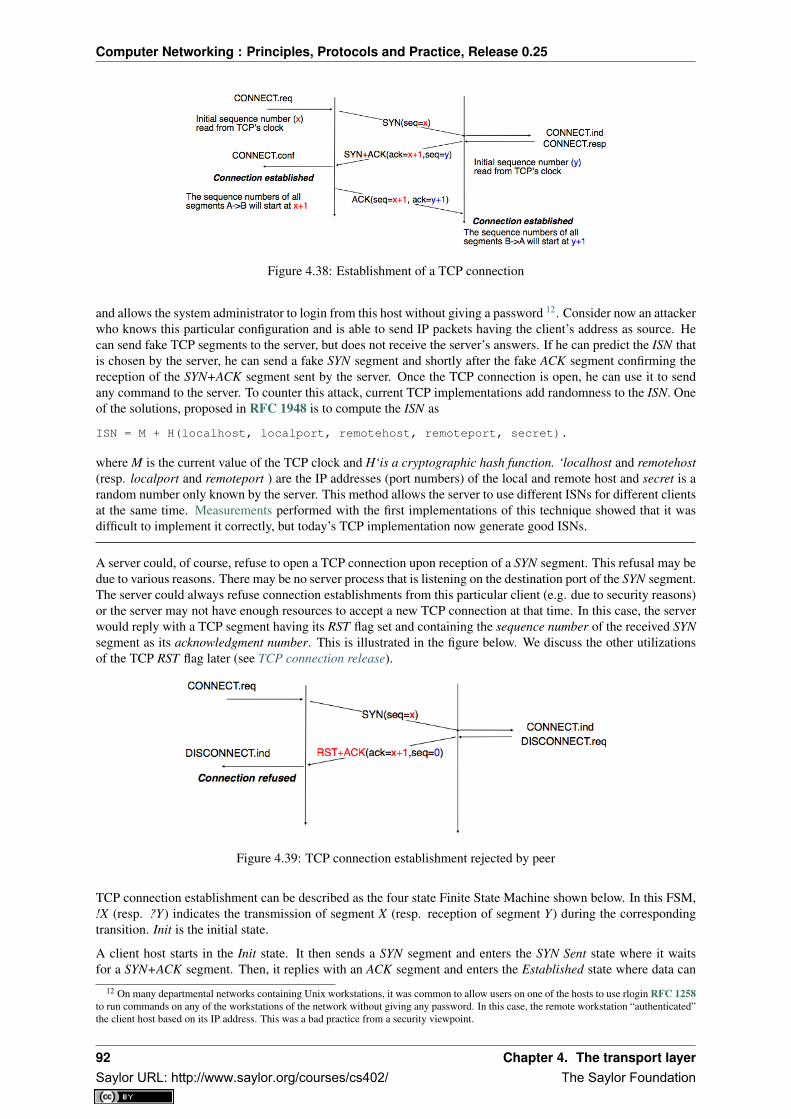
Computer Networking : Principles, Protocols and Practice, Release 0.25
Figure 4.38: Establishment of a TCP connection
and allows the system administrator to login from this host without giving a password 12. Consider now an attackerwho knows this particular configuration and is able to send IP packets having the client’s address as source. Hecan send fake TCP segments to the server, but does not receive the server’s answers. If he can predict the ISN thatis chosen by the server, he can send a fake SYN segment and shortly after the fake ACK segment confirming thereception of the SYN+ACK segment sent by the server. Once the TCP connection is open, he can use it to sendany command to the server. To counter this attack, current TCP implementations add randomness to the ISN. Oneof the solutions, proposed in RFC 1948 is to compute the ISN as
ISN = M + H(localhost, localport, remotehost, remoteport, secret).
where M is the current value of the TCP clock and H‘is a cryptographic hash function. ‘localhost and remotehost(resp. localport and remoteport ) are the IP addresses (port numbers) of the local and remote host and secret is arandom number only known by the server. This method allows the server to use different ISNs for different clientsat the same time. Measurements performed with the first implementations of this technique showed that it wasdifficult to implement it correctly, but today’s TCP implementation now generate good ISNs.
A server could, of course, refuse to open a TCP connection upon reception of a SYN segment. This refusal may bedue to various reasons. There may be no server process that is listening on the destination port of the SYN segment.The server could always refuse connection establishments from this particular client (e.g. due to security reasons)or the server may not have enough resources to accept a new TCP connection at that time. In this case, the serverwould reply with a TCP segment having its RST flag set and containing the sequence number of the received SYNsegment as its acknowledgment number. This is illustrated in the figure below. We discuss the other utilizationsof the TCP RST flag later (see TCP connection release).
Figure 4.39: TCP connection establishment rejected by peer
TCP connection establishment can be described as the four state Finite State Machine shown below. In this FSM,!X (resp. ?Y) indicates the transmission of segment X (resp. reception of segment Y) during the correspondingtransition. Init is the initial state.
A client host starts in the Init state. It then sends a SYN segment and enters the SYN Sent state where it waitsfor a SYN+ACK segment. Then, it replies with an ACK segment and enters the Established state where data can
12 On many departmental networks containing Unix workstations, it was common to allow users on one of the hosts to use rlogin RFC 1258to run commands on any of the workstations of the network without giving any password. In this case, the remote workstation “authenticated”the client host based on its IP address. This was a bad practice from a security viewpoint.
92 Chapter 4. The transport layerSaylor URL: http://www.saylor.org/courses/cs402/ The Saylor Foundation

Computer Networking : Principles, Protocols and Practice, Release 0.25
Figure 4.40: TCP FSM for connection establishment
be exchanged. On the other hand, a server host starts in the Init state. When a server process starts to listen toa destination port, the underlying TCP entity creates a TCP control block and a queue to process incoming SYNsegments. Upon reception of a SYN segment, the server’s TCP entity replies with a SYN+ACK and enters the SYNRCVD state. It remains in this state until it receives an ACK segment that acknowledges its SYN+ACK segment,with this it then enters the Established state.
Apart from these two paths in the TCP connection establishment FSM, there is a third path that corresponds to thecase when both the client and the server send a SYN segment to open a TCP connection 13. In this case, the clientand the server send a SYN segment and enter the SYN Sent state. Upon reception of the SYN segment sent by theother host, they reply by sending a SYN+ACK segment and enter the SYN RCVD state. The SYN+ACK that arrivesfrom the other host allows it to transition to the Established state. The figure below illustrates such a simultaneousestablishment of a TCP connection.
Figure 4.41: Simultaneous establishment of a TCP connection
13 Of course, such a simultaneous TCP establishment can only occur if the source port chosen by the client is equal to the destinationport chosen by the server. This may happen when a host can serve both as a client as a server or in peer-to-peer applications when thecommunicating hosts do not use ephemeral port numbers.
4.3. The Transmission Control Protocol 93Saylor URL: http://www.saylor.org/courses/cs402/ The Saylor Foundation

Computer Networking : Principles, Protocols and Practice, Release 0.25
Denial of Service attacks
When a TCP entity opens a TCP connection, it creates a Transmission Control Block (TCB). The TCBcontains the entire state that is maintained by the TCP entity for each TCP connection. During connectionestablishment, the TCB contains the local IP address, the remote IP address, the local port number, theremote port number, the current local sequence number, the last sequence number received from the remoteentity. Until the mid 1990s, TCP implementations had a limit on the number of TCP connections that couldbe in the SYN RCVD state at a given time. Many implementations set this limit to about 100 TCBs. This limitwas considered sufficient even for heavily load http servers given the small delay between the reception of aSYN segment and the reception of the ACK segment that terminates the establishment of the TCP connection.When the limit of 100 TCBs in the SYN Rcvd state is reached, the TCP entity discards all received TCP SYNsegments that do not correspond to an existing TCB.This limit of 100 TCBs in the SYN Rcvd state was chosen to protect the TCP entity from the risk of overload-ing its memory with too many TCBs in the SYN Rcvd state. However, it was also the reason for a new type ofDenial of Service (DoS) attack RFC 4987. A DoS attack is defined as an attack where an attacker can rendera resource unavailable in the network. For example, an attacker may cause a DoS attack on a 2 Mbps linkused by a company by sending more than 2 Mbps of packets through this link. In this case, the DoS attackwas more subtle. As a TCP entity discards all received SYN segments as soon as it has 100 TCBs in the SYNRcvd state, an attacker simply had to send a few 100 SYN segments every second to a server and never replyto the received SYN+ACK segments. To avoid being caught, attackers were of course sending these SYNsegments with a different address than their own IP address a. On most TCP implementations, once a TCBentered the SYN Rcvd state, it remained in this state for several seconds, waiting for a retransmission of theinitial SYN segment. This attack was later called a SYN flood attack and the servers of the ISP named panixwere among the first to be affected by this attack.To avoid the SYN flood attacks, recent TCP implementations no longer enter the SYN Rcvd state upon recep-tion of a SYN segment. Instead, they reply directly with a SYN+ACK segment and wait until the receptionof a valid ACK. This implementation trick is only possible if the TCP implementation is able to verify thatthe received ACK segment acknowledges the SYN+ACK segment sent earlier without storing the initial se-quence number of this SYN+ACK segment in a TCB. The solution to solve this problem, which is known asSYN cookies is to compute the 32 bits of the ISN as follows :
• the high order bits contain the low order bits of a counter that is incremented slowly• the low order bits contain a hash value computed over the local and remote IP addresses and ports and
a random secret only known to the serverThe advantage of the SYN cookies is that by using them, the server does not need to create a TCB uponreception of the SYN segment and can still check the returned ACK segment by recomputing the SYN cookie.
a Sending a packet with a different source IP address than the address allocated to the host is called sending a spoofed packet.
Retransmitting the first SYN segment
As IP provides an unreliable connectionless service, the SYN and SYN+ACK segments sent to open a TCPconnection could be lost. Current TCP implementations start a retransmission timer when they send the firstSYN segment. This timer is often set to three seconds for the first retransmission and then doubles after eachretransmission RFC 2988. TCP implementations also enforce a maximum number of retransmissions forthe initial SYN segment.
As explained earlier, TCP segments may contain an optional header extension. In the SYN and SYN+ACK seg-ments, these options are used to negotiate some parameters and the utilisation of extensions to the basic TCPspecification.
The first parameter which is negotiated during the establishment of a TCP connection is the Maximum SegmentSize (MSS). The MSS is the size of the largest segment that a TCP entity is able to process. According to RFC879, all TCP implementations must be able to receive TCP segments containing 536 bytes of payload. However,most TCP implementations are able to process larger segments. Such TCP implementations use the TCP MSSOption in the SYN/SYN+ACK segment to indicate the largest segment they are able to process. The MSS valueindicates the maximum size of the payload of the TCP segments. The client (resp. server) stores in its TCB theMSS value announced by the server (resp. the client).
94 Chapter 4. The transport layerSaylor URL: http://www.saylor.org/courses/cs402/ The Saylor Foundation
Computer Networking : Principles, Protocols and Practice, Release 0.25
Another utilisation of TCP options during connection establishment is to enable TCP extensions. For example,consider RFC 1323 (which is discussed in TCP reliable data transfer). RFC 1323 defines TCP extensions tosupport timestamps and larger windows. If the client supports RFC 1323, it adds a RFC 1323 option to its SYNsegment. If the server understands this RFC 1323 option and wishes to use it, it replies with an RFC 1323option in the SYN+ACK segment and the extension defined in RFC 1323 is used throughout the TCP connection.Otherwise, if the server’s SYN+ACK does not contain the RFC 1323 option, the client is not allowed to use thisextension and the corresponding TCP header options throughout the TCP connection. TCP’s option mechanismis flexible and it allows the extension of TCP while maintaining compatibility with older implementations.
The TCP options are encoded by using a Type Length Value format where :
• the first byte indicates the type of the option.
• the second byte indicates the total length of the option (including the first two bytes) in bytes
• the last bytes are specific for each type of option
RFC 793 defines the Maximum Segment Size (MSS) TCP option that must be understood by all TCP implemen-tations. This option (type 2) has a length of 4 bytes and contains a 16 bits word that indicates the MSS supportedby the sender of the SYN segment. The MSS option can only be used in TCP segments having the SYN flag set.
RFC 793 also defines two special options that must be supported by all TCP implementations. The first optionis End of option. It is encoded as a single byte having value 0x00 and can be used to ensure that the TCP headerextension ends on a 32 bits boundary. The No-Operation option, encoded as a single byte having value 0x01, canbe used when the TCP header extension contains several TCP options that should be aligned on 32 bit boundaries.All other options 14 are encoded by using the TLV format.
Note: The robustness principle
The handling of the TCP options by TCP implementations is one of the many applications of the robustnessprinciple which is usually attributed to Jon Postel and is often quoted as “Be liberal in what you accept, andconservative in what you send” RFC 1122
Concerning the TCP options, the robustness principle implies that a TCP implementation should be able to acceptTCP options that it does not understand, in particular in received SYN segments, and that it should be able to parseany received segment without crashing, even if the segment contains an unknown TCP option. Furthermore, aserver should not send in the SYN+ACK segment or later, options that have not been proposed by the client in theSYN segment.
4.3.2 TCP connection release
TCP, like most connection-oriented transport protocols, supports two types of connection release :
• graceful connection release, where each TCP user can release its own direction of data transfer
• abrupt connection release, where either one user closes both directions of data transfer or one TCP entityis forced to close the connection (e.g. because the remote host does not reply anymore or due to lack ofresources)
The abrupt connection release mechanism is very simple and relies on a single segment having the RST bit set. ATCP segment containing the RST bit can be sent for the following reasons :
• a non-SYN segment was received for a non-existing TCP connection RFC 793
• by extension, some implementations respond with an RST segment to a segment that is received on anexisting connection but with an invalid header RFC 3360. This causes the corresponding connection to beclosed and has caused security attacks RFC 4953
• by extension, some implementations send an RST segment when they need to close an existing TCP con-nection (e.g. because there are not enough resources to support this connection or because the remote hostis considered to be unreachable). Measurements have shown that this usage of TCP RST was widespread[AW05]
14 The full list of all TCP options may be found at http://www.iana.org/assignments/tcp-parameters/
4.3. The Transmission Control Protocol 95Saylor URL: http://www.saylor.org/courses/cs402/ The Saylor Foundation

Computer Networking : Principles, Protocols and Practice, Release 0.25
When an RST segment is sent by a TCP entity, it should contain the current value of the sequence number for theconnection (or 0 if it does not belong to any existing connection) and the acknowledgement number should be setto the next expected in-sequence sequence number on this connection.
Note: TCP RST wars
TCP implementers should ensure that two TCP entities never enter a TCP RST war where host A is sending a RSTsegment in response to a previous RST segment that was sent by host B in response to a TCP RST segment sent byhost A ... To avoid such an infinite exchange of RST segments that do not carry data, a TCP entity is never allowedto send a RST segment in response to another RST segment.
The normal way of terminating a TCP connection is by using the graceful TCP connection release. This mecha-nism uses the FIN flag of the TCP header and allows each host to release its own direction of data transfer. As forthe SYN flag, the utilisation of the FIN flag in the TCP header consumes one sequence number. The figure FSMfor TCP connection release shows the part of the TCP FSM used when a TCP connection is released.
Figure 4.42: FSM for TCP connection release
Starting from the Established state, there are two main paths through this FSM.
The first path is when the host receives a segment with sequence number x and the FIN flag set. The utilisation ofthe FIN flag indicates that the byte before sequence number x was the last byte of the byte stream sent by the remotehost. Once all of the data has been delivered to the user, the TCP entity sends an ACK segment whose ack field isset to (x+ 1)mod 232 to acknowledge the FIN segment. The FIN segment is subject to the same retransmissionmechanisms as a normal TCP segment. In particular, its transmission is protected by the retransmission timer.At this point, the TCP connection enters the CLOSE_WAIT state. In this state, the host can still send data to theremote host. Once all its data have been sent, it sends a FIN segment and enter the LAST_ACK state. In this state,the TCP entity waits for the acknowledgement of its FIN segment. It may still retransmit unacknowledged datasegments e.g. if the retransmission timer expires. Upon reception of the acknowledgement for the FIN segment,the TCP connection is completely closed and its TCB can be discarded.
The second path is when the host decides first to send a FIN segment. In this case, it enters the FIN_WAIT1state. It this state, it can retransmit unacknowledged segments but cannot send new data segments. It waits for anacknowledgement of its FIN segment, but may receive a FIN segment sent by the remote host. In the first case,the TCP connection enters the FIN_WAIT2 state. In this state, new data segments from the remote host are stillaccepted until the reception of the FIN segment. The acknowledgement for this FIN segment is sent once all datareceived before the FIN segment have been delivered to the user and the connection enters the TIME_WAIT state.In the second case, a FIN segment is received and the connection enters the Closing state once all data receivedfrom the remote host have been delivered to the user. In this state, no new data segments can be sent and the hostwaits for an acknowledgement of its FIN segment before entering the TIME_WAIT state.
The TIME_WAIT state is different from the other states of the TCP FSM. A TCP entity enters this state afterhaving sent the last ACK segment on a TCP connection. This segment indicates to the remote host that all thedata that it has sent have been correctly received and that it can safely release the TCP connection and discard
96 Chapter 4. The transport layerSaylor URL: http://www.saylor.org/courses/cs402/ The Saylor Foundation

Computer Networking : Principles, Protocols and Practice, Release 0.25
the corresponding TCB. After having sent the last ACK segment, a TCP connection enters the TIME_WAIT andremains in this state for 2 ∗MSL seconds. During this period, the TCB of the connection is maintained. Thisensures that the TCP entity that sent the last ACK maintains enough state to be able to retransmit this segmentif this ACK segment is lost and the remote host retransmits its last FIN segment or another one. The delay of2 ∗ MSL seconds ensures that any duplicate segments on the connection would be handled correctly withoutcausing the transmission of an RST segment. Without the TIME_WAIT state and the 2 ∗MSL seconds delay, theconnection release would not be graceful when the last ACK segment is lost.
Note: TIME_WAIT on busy TCP servers
The 2 ∗ MSL seconds delay in the TIME_WAIT state is an important operational problem on servers havingthousands of simultaneously opened TCP connections [FTY99]. Consider for example a busy web server thatprocesses 10.000 TCP connections every second. If each of these connections remain in the TIME_WAIT statefor 4 minutes, this implies that the server would have to maintain more than 2 million TCBs at any time. For thisreason, some TCP implementations prefer to perform an abrupt connection release by sending a RST segment toclose the connection [AW05] and immediately discard the corresponding TCB. However, if the RST segment islost, the remote host continues to maintain a TCB for a connection no longer exists. This optimisation reduces thenumber of TCBs maintained by the host sending the RST segment but at the potential cost of increased processingon the remote host when the RST segment is lost.
4.3.3 TCP reliable data transfer
The original TCP data transfer mechanisms were defined in RFC 793. Based on the experience of using TCPon the growing global Internet, this part of the TCP specification has been updated and improved several times,always while preserving the backward compatibility with older TCP implementations. In this section, we reviewthe main data transfer mechanisms used by TCP.
TCP is a window-based transport protocol that provides a bi-directional byte stream service. This has severalimplications on the fields of the TCP header and the mechanisms used by TCP. The three fields of the TCP headerare :
• sequence number. TCP uses a 32 bits sequence number. The sequence number placed in the header of aTCP segment containing data is the sequence number of the first byte of the payload of the TCP segment.
• acknowledgement number. TCP uses cumulative positive acknowledgements. Each TCP segment containsthe sequence number of the next byte that the sender of the acknowledgement expects to receive from theremote host. In theory, the acknowledgement number is only valid if the ACK flag of the TCP header is set.In practice almost all 15 TCP segments have their ACK flag set.
• window. a TCP receiver uses this 16 bits field to indicate the current size of its receive window expressedin bytes.
Note: The Transmission Control Block
For each established TCP connection, a TCP implementation must maintain a Transmission Control Block (TCB).A TCB contains all the information required to send and receive segments on this connection RFC 793. Thisincludes 16 :
• the local IP address
• the remote IP address
• the local TCP port number
• the remote TCP port number
• the current state of the TCP FSM
• the maximum segment size (MSS)
15 In practice, only the SYN segment do not have their ACK flag set.16 A complete TCP implementation contains additional information in its TCB, notably to support the urgent pointer. However, this part of
TCP is not discussed in this book. Refer to RFC 793 and RFC 2140 for more details about the TCB.
4.3. The Transmission Control Protocol 97Saylor URL: http://www.saylor.org/courses/cs402/ The Saylor Foundation

Computer Networking : Principles, Protocols and Practice, Release 0.25
• snd.nxt : the sequence number of the next byte in the byte stream (the first byte of a new data segment thatyou send uses this sequence number)
• snd.una : the earliest sequence number that has been sent but has not yet been acknowledged
• snd.wnd : the current size of the sending window (in bytes)
• rcv.nxt : the sequence number of the next byte that is expected to be received from the remote host
• rcv.wnd : the current size of the receive window advertised by the remote host
• sending buffer : a buffer used to store all unacknowledged data
• receiving buffer : a buffer to store all data received from the remote host that has not yet been deliveredto the user. Data may be stored in the receiving buffer because either it was not received in sequence orbecause the user is too slow to process it
The original TCP specification can be categorised as a transport protocol that provides a byte stream service anduses go-back-n.
To send new data on an established connection, a TCP entity performs the following operations on the correspond-ing TCB. It first checks that the sending buffer does not contain more data than the receive window advertised bythe remote host (rcv.wnd). If the window is not full, up to MSS bytes of data are placed in the payload of a TCPsegment. The sequence number of this segment is the sequence number of the first byte of the payload. It is set tothe first available sequence number : snd.nxt and snd.nxt is incremented by the length of the payload of the TCPsegment. The acknowledgement number of this segment is set to the current value of rcv.nxt and the window fieldof the TCP segment is computed based on the current occupancy of the receiving buffer. The data is kept in thesending buffer in case it needs to be retransmitted later.
When a TCP segment with the ACK flag set is received, the following operations are performed. rcv.wnd is set tothe value of the window field of the received segment. The acknowledgement number is compared to snd.una. Thenewly acknowledged data is remove from the sending buffer and snd.una is updated. If the TCP segment containeddata, the sequence number is compared to rcv.nxt. If they are equal, the segment was received in sequence andthe data can be delivered to the user and rcv.nxt is updated. The contents of the receiving buffer is checked to seewhether other data already present in this buffer can be delivered in sequence to the user. If so, rcv.nxt is updatedagain. Otherwise, the segment’s payload is placed in the receiving buffer.
Segment transmission strategies
In a transport protocol such as TCP that offers a bytestream, a practical issue that was left as an implementationchoice in RFC 793 is to decide when a new TCP segment containing data must be sent. There are two simple andextreme implementation choices. The first implementation choice is to send a TCP segment as soon as the userhas requested the transmission of some data. This allows TCP to provide a low delay service. However, if theuser is sending data one byte at a time, TCP would place each user byte in a segment containing 20 bytes of TCPheader 17. This is a huge overhead that is not acceptable in wide area networks. A second simple solution wouldbe to only transmit a new TCP segment once the user has produced MSS bytes of data. This solution reduces theoverhead, but at the cost of a potentially very high delay.
An elegant solution to this problem was proposed by John Nagle in RFC 896. John Nagle observed that theoverhead caused by the TCP header was a problem in wide area connections, but less in local area connectionswhere the available bandwidth is usually higher. He proposed the following rules to decide to send a new datasegment when a new data has been produced by the user or a new ack segment has been received
if rcv.wnd>= MSS and len(data) >= MSS :send one MSS-sized segment
elseif there are unacknowledged data:
place data in buffer until acknowledgement has been receivedelse
send one TCP segment containing all buffered data
17 This TCP segment is then placed in an IP header. We describe IPv4 and IPv6 in the next chapter. The minimum size of the IPv4 (resp.IPv6) header is 20 bytes (resp. 40 bytes).
98 Chapter 4. The transport layerSaylor URL: http://www.saylor.org/courses/cs402/ The Saylor Foundation

Computer Networking : Principles, Protocols and Practice, Release 0.25
The first rule ensures that a TCP connection used for bulk data transfer always sends full TCP segments. Thesecond rule sends one partially filled TCP segment every round-trip-time.
This algorithm, called the Nagle algorithm, takes a few lines of code in all TCP implementations. These lines ofcode have a huge impact on the packets that are exchanged in TCP/IP networks. Researchers have analysed thedistribution of the packet sizes by capturing and analysing all the packets passing through a given link. Thesestudies have shown several important results :
• in TCP/IPv4 networks, a large fraction of the packets are TCP segments that contain only an acknowledge-ment. These packets usually account for 40-50% of the packets passing through the studied link
• in TCP/IPv4 networks, most of the bytes are exchanged in long packets, usually packets containing up to1460 bytes of payload which is the default MSS for hosts attached to an Ethernet network, the most populartype of LAN
The figure below provides a distribution of the packet sizes measured on a link. It shows a three-modal distributionof the packet size. 50% of the packets contain pure TCP acknowledgements and occupy 40 bytes. About 20%of the packets contain about 500 bytes 18 of user data and 12% of the packets contain 1460 bytes of user data.However, most of the user data is transported in large packets. This packet size distribution has implications onthe design of routers as we discuss in the next chapter.
Figure 4.43: Packet size distribution in the Internet
Recent measurements indicate that these packet size distributions are still valid in today’s Internet, although thepacket distribution tends to become bimodal with small packets corresponding to TCP pure acks (40-64 bytesdepending on the utilisation of TCP options) and large 1460-bytes packets carrying most of the user data.
TCP windows
From a performance point of view, one of the main limitations of the original TCP specification is the 16 bitswindow field in the TCP header. As this field indicates the current size of the receive window in bytes, it limits theTCP receive window at 65535 bytes. This limitation was not a severe problem when TCP was designed since atthat time high-speed wide area networks offered a maximum bandwidth of 56 kbps. However, in today’s network,this limitation is not acceptable anymore. The table below provides the rough 19 maximum throughput that can beachieved by a TCP connection with a 64 KBytes window in function of the connection’s round-trip-time
RTT Maximum Throughput1 msec 524 Mbps10 msec 52.4 Mbps100 msec 5.24 Mbps500 msec 1.05 Mbps
To solve this problem, a backward compatible extension that allows TCP to use larger receive windows wasproposed in RFC 1323. Today, most TCP implementations support this option. The basic idea is that instead of
18 When these measurements were taken, some hosts had a default MSS of 552 bytes (e.g. BSD Unix derivatives) or 536 bytes (the defaultMSS specified in RFC 793). Today, most TCP implementation derive the MSS from the maximum packet size of the LAN interface they use(Ethernet in most cases).
19 A precise estimation of the maximum bandwidth that can be achieved by a TCP connection should take into account the overhead of theTCP and IP headers as well.
4.3. The Transmission Control Protocol 99Saylor URL: http://www.saylor.org/courses/cs402/ The Saylor Foundation

Computer Networking : Principles, Protocols and Practice, Release 0.25
storing snd.wnd and rcv.wnd as 16 bits integers in the TCB, they should be stored as 32 bits integers. As the TCPsegment header only contains 16 bits to place the window field, it is impossible to copy the value of snd.wnd ineach sent TCP segment. Instead the header contains snd.wnd >> S where S is the scaling factor ( 0 ≤ S ≤ 14)negotiated during connection establishment. The client adds its proposed scaling factor as a TCP option in theSYN segment. If the server supports RFC 1323, it places in the SYN+ACK segment the scaling factor that it useswhen advertising its own receive window. The local and remote scaling factors are included in the TCB. If theserver does not support RFC 1323, it ignores the received option and no scaling is applied.
By using the window scaling extensions defined in RFC 1323, TCP implementations can use a receive bufferof up to 1 GByte. With such a receive buffer, the maximum throughput that can be achieved by a single TCPconnection becomes :
RTT Maximum Throughput1 msec 8590 Gbps10 msec 859 Gbps100 msec 86 Gbps500 msec 17 Gbps
These throughputs are acceptable in today’s networks. However, there are already servers having 10 Gbps in-terfaces... Early TCP implementations had fixed receiving and sending buffers 20. Today’s high performanceimplementations are able to automatically adjust the size of the sending and receiving buffer to better support highbandwidth flows [SMM1998]
TCP’s retransmission timeout
In a go-back-n transport protocol such as TCP, the retransmission timeout must be correctly set in order to achievegood performance. If the retransmission timeout expires too early, then bandwidth is wasted by retransmittingsegments that have already been correctly received; whereas if the retransmission timeout expires too late, thenbandwidth is wasted because the sender is idle waiting for the expiration of its retransmission timeout.
A good setting of the retransmission timeout clearly depends on an accurate estimation of the round-trip-time ofeach TCP connection. The round-trip-time differs between TCP connections, but may also change during thelifetime of a single connection. For example, the figure below shows the evolution of the round-trip-time betweentwo hosts during a period of 45 seconds.
Figure 4.44: Evolution of the round-trip-time between two hosts
The easiest solution to measure the round-trip-time on a TCP connection is to measure the delay between thetransmission of a data segment and the reception of a corresponding acknowledgement 21. As illustrated in the
20 See http://fasterdata.es.net/tuning.html for more information on how to tune a TCP implementation21 In theory, a TCP implementation could store the timestamp of each data segment transmitted and compute a new estimate for the round-
trip-time upon reception of the corresponding acknowledgement. However, using such frequent measurements introduces a lot of noise inpractice and many implementations still measure the round-trip-time once per round-trip-time by recording the transmission time of onesegment at a time RFC 2988
100 Chapter 4. The transport layerSaylor URL: http://www.saylor.org/courses/cs402/ The Saylor Foundation

Computer Networking : Principles, Protocols and Practice, Release 0.25
figure below, this measurement works well when there are no segment losses.
Figure 4.45: How to measure the round-trip-time ?
However, when a data segment is lost, as illustrated in the bottom part of the figure, the measurement is ambiguousas the sender cannot determine whether the received acknowledgement was triggered by the first transmission ofsegment 123 or its retransmission. Using incorrect round-trip-time estimations could lead to incorrect values ofthe retransmission timeout. For this reason, Phil Karn and Craig Partridge proposed, in [KP91], to ignore theround-trip-time measurements performed during retransmissions.
To avoid this ambiguity in the estimation of the round-trip-time when segments are retransmitted, recent TCPimplementations rely on the timestamp option defined in RFC 1323. This option allows a TCP sender to placetwo 32 bit timestamps in each TCP segment that it sends. The first timestamp, TS Value (TSval) is chosen by thesender of the segment. It could for example be the current value of its real-time clock 22. The second value, TSEcho Reply (TSecr), is the last TSval that was received from the remote host and stored in the TCB. The figurebelow shows how the utilization of this timestamp option allows for the disambiguation of the round-trip-timemeasurement when there are retransmissions.
Figure 4.46: Disambiguating round-trip-time measurements with the RFC 1323 timestamp option
Once the round-trip-time measurements have been collected for a given TCP connection, the TCP entity mustcompute the retransmission timeout. As the round-trip-time measurements may change during the lifetime of aconnection, the retransmission timeout may also change. At the beginning of a connection 23 , the TCP entity thatsends a SYN segment does not know the round-trip-time to reach the remote host and the initial retransmissiontimeout is usually set to 3 seconds RFC 2988.
The original TCP specification proposed in RFC 793 to include two additional variables in the TCB :
• srtt : the smoothed round-trip-time computed as srrt = (α × srtt) + ((1 − α) × rtt) where rtt is theround-trip-time measured according to the above procedure and α a smoothing factor (e.g. 0.8 or 0.9)
22 Some security experts have raised concerns that using the real-time clock to set the TSval in the timestamp option can leak informationsuch as the system’s up-time. Solutions proposed to solve this problem may be found in [CNPI09]
23 As a TCP client often establishes several parallel or successive connections with the same server, RFC 2140 has proposed to reuse fora new connection some information that was collected in the TCB of a previous connection, such as the measured rtt. However, this solutionhas not been widely implemented.
4.3. The Transmission Control Protocol 101Saylor URL: http://www.saylor.org/courses/cs402/ The Saylor Foundation

Computer Networking : Principles, Protocols and Practice, Release 0.25
• rto : the retransmission timeout is computed as rto = min(60,max(1, β × srtt)) where β is used to takeinto account the delay variance (value : 1.3 to 2.0). The 60 and 1 constants are used to ensure that the rto isnot larger than one minute nor smaller than 1 second.
However, in practice, this computation for the retransmission timeout did not work well. The main problem wasthat the computed rto did not correctly take into account the variations in the measured round-trip-time. Van Ja-cobson proposed in his seminal paper [Jacobson1988] an improved algorithm to compute the rto and implementedit in the BSD Unix distribution. This algorithm is now part of the TCP standard RFC 2988.
Jacobson’s algorithm uses two state variables, srtt the smoothed rtt and rttvar the estimation of the variance ofthe rtt and two parameters : α and β. When a TCP connection starts, the first rto is set to 3 seconds. When a firstestimation of the rtt is available, the srtt, rttvar and rto are computed as
srtt=rttrttvar=rtt/2rto=srtt+4*rttvar
Then, when other rtt measurements are collected, srtt and rttvar are updated as follows :
rttvar = (1− β)× rttvar + β × |srtt− rtt|
srtt = (1− α)× srtt+ α× rtt
rto = srtt+ 4× rttvar
The proposed values for the parameters are α = 18 and β = 1
4 . This allows a TCP implementation, implementedin the kernel, to perform the rtt computation by using shift operations instead of the more costly floating pointoperations [Jacobson1988]. The figure below illustrates the computation of the rto upon rtt changes.
Figure 4.47: Example computation of the rto
Advanced retransmission strategies
The default go-back-n retransmission strategy was defined in RFC 793. When the retransmission timer expires,TCP retransmits the first unacknowledged segment (i.e. the one having sequence number snd.una). After eachexpiration of the retransmission timeout, RFC 2988 recommends to double the value of the retransmission time-out. This is called an exponential backoff. This doubling of the retransmission timeout after a retransmissionwas included in TCP to deal with issues such as network/receiver overload and incorrect initial estimations of theretransmission timeout. If the same segment is retransmitted several times, the retransmission timeout is doubledafter every retransmission until it reaches a configured maximum. RFC 2988 suggests a maximum retransmissiontimeout of at least 60 seconds. Once the retransmission timeout reaches this configured maximum, the remotehost is considered to be unreachable and the TCP connection is closed.
This retransmission strategy has been refined based on the experience of using TCP on the Internet. The firstrefinement was a clarification of the strategy used to send acknowledgements. As TCP uses piggybacking, the
102 Chapter 4. The transport layerSaylor URL: http://www.saylor.org/courses/cs402/ The Saylor Foundation
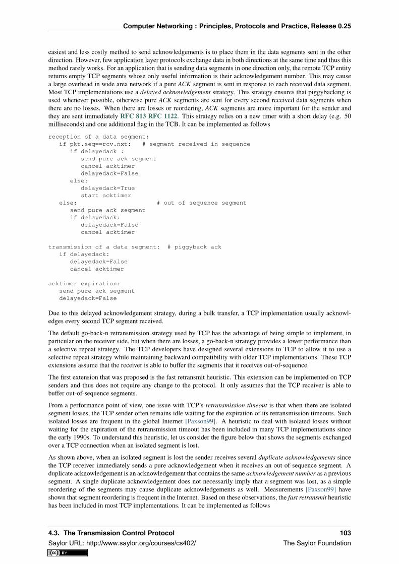
Computer Networking : Principles, Protocols and Practice, Release 0.25
easiest and less costly method to send acknowledgements is to place them in the data segments sent in the otherdirection. However, few application layer protocols exchange data in both directions at the same time and thus thismethod rarely works. For an application that is sending data segments in one direction only, the remote TCP entityreturns empty TCP segments whose only useful information is their acknowledgement number. This may causea large overhead in wide area network if a pure ACK segment is sent in response to each received data segment.Most TCP implementations use a delayed acknowledgement strategy. This strategy ensures that piggybacking isused whenever possible, otherwise pure ACK segments are sent for every second received data segments whenthere are no losses. When there are losses or reordering, ACK segments are more important for the sender andthey are sent immediately RFC 813 RFC 1122. This strategy relies on a new timer with a short delay (e.g. 50milliseconds) and one additional flag in the TCB. It can be implemented as follows
reception of a data segment:if pkt.seq==rcv.nxt: # segment received in sequence
if delayedack :send pure ack segmentcancel acktimerdelayedack=False
else:delayedack=Truestart acktimer
else: # out of sequence segmentsend pure ack segmentif delayedack:
delayedack=Falsecancel acktimer
transmission of a data segment: # piggyback ackif delayedack:
delayedack=Falsecancel acktimer
acktimer expiration:send pure ack segmentdelayedack=False
Due to this delayed acknowledgement strategy, during a bulk transfer, a TCP implementation usually acknowl-edges every second TCP segment received.
The default go-back-n retransmission strategy used by TCP has the advantage of being simple to implement, inparticular on the receiver side, but when there are losses, a go-back-n strategy provides a lower performance thana selective repeat strategy. The TCP developers have designed several extensions to TCP to allow it to use aselective repeat strategy while maintaining backward compatibility with older TCP implementations. These TCPextensions assume that the receiver is able to buffer the segments that it receives out-of-sequence.
The first extension that was proposed is the fast retransmit heuristic. This extension can be implemented on TCPsenders and thus does not require any change to the protocol. It only assumes that the TCP receiver is able tobuffer out-of-sequence segments.
From a performance point of view, one issue with TCP’s retransmission timeout is that when there are isolatedsegment losses, the TCP sender often remains idle waiting for the expiration of its retransmission timeouts. Suchisolated losses are frequent in the global Internet [Paxson99]. A heuristic to deal with isolated losses withoutwaiting for the expiration of the retransmission timeout has been included in many TCP implementations sincethe early 1990s. To understand this heuristic, let us consider the figure below that shows the segments exchangedover a TCP connection when an isolated segment is lost.
As shown above, when an isolated segment is lost the sender receives several duplicate acknowledgements sincethe TCP receiver immediately sends a pure acknowledgement when it receives an out-of-sequence segment. Aduplicate acknowledgement is an acknowledgement that contains the same acknowledgement number as a previoussegment. A single duplicate acknowledgement does not necessarily imply that a segment was lost, as a simplereordering of the segments may cause duplicate acknowledgements as well. Measurements [Paxson99] haveshown that segment reordering is frequent in the Internet. Based on these observations, the fast retransmit heuristichas been included in most TCP implementations. It can be implemented as follows
4.3. The Transmission Control Protocol 103Saylor URL: http://www.saylor.org/courses/cs402/ The Saylor Foundation
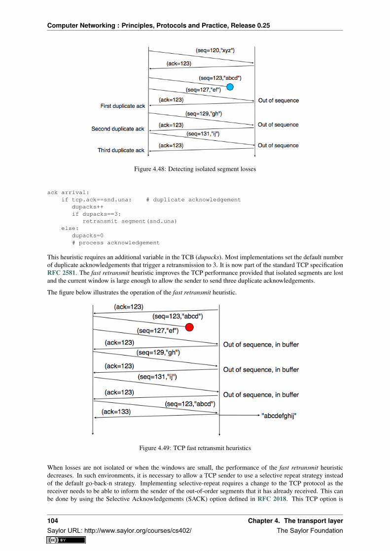
Computer Networking : Principles, Protocols and Practice, Release 0.25
Figure 4.48: Detecting isolated segment losses
ack arrival:if tcp.ack==snd.una: # duplicate acknowledgement
dupacks++if dupacks==3:
retransmit segment(snd.una)else:
dupacks=0# process acknowledgement
This heuristic requires an additional variable in the TCB (dupacks). Most implementations set the default numberof duplicate acknowledgements that trigger a retransmission to 3. It is now part of the standard TCP specificationRFC 2581. The fast retransmit heuristic improves the TCP performance provided that isolated segments are lostand the current window is large enough to allow the sender to send three duplicate acknowledgements.
The figure below illustrates the operation of the fast retransmit heuristic.
Figure 4.49: TCP fast retransmit heuristics
When losses are not isolated or when the windows are small, the performance of the fast retransmit heuristicdecreases. In such environments, it is necessary to allow a TCP sender to use a selective repeat strategy insteadof the default go-back-n strategy. Implementing selective-repeat requires a change to the TCP protocol as thereceiver needs to be able to inform the sender of the out-of-order segments that it has already received. This canbe done by using the Selective Acknowledgements (SACK) option defined in RFC 2018. This TCP option is
104 Chapter 4. The transport layerSaylor URL: http://www.saylor.org/courses/cs402/ The Saylor Foundation

Computer Networking : Principles, Protocols and Practice, Release 0.25
negotiated during the establishment of a TCP connection. If both TCP hosts support the option, SACK blocks canbe attached by the receiver to the segments that it sends. SACK blocks allow a TCP receiver to indicate the blocksof data that it has received correctly but out of sequence. The figure below illustrates the utilisation of the SACKblocks.
Figure 4.50: TCP selective acknowledgements
An SACK option contains one or more blocks. A block corresponds to all the sequence numbers between the leftedge and the right edge of the block. The two edges of the block are encoded as 32 bit numbers (the same size asthe TCP sequence number) in an SACK option. As the SACK option contains one byte to encode its type and onebyte for its length, a SACK option containing b blocks is encoded as a sequence of 2 + 8 × b bytes. In practice,the size of the SACK option can be problematic as the optional TCP header extension cannot be longer than 44bytes. As the SACK option is usually combined with the RFC 1323 timestamp extension, this implies that a TCPsegment cannot usually contain more than three SACK blocks. This limitation implies that a TCP receiver cannotalways place in the SACK option that it sends, information about all the received blocks.
To deal with the limited size of the SACK option, a TCP receiver currently having more than 3 blocks inside itsreceiving buffer must select the blocks to place in the SACK option. A good heuristic is to put in the SACK optionthe blocks that have most recently changed, as the sender is likely to be already aware of the older blocks.
When a sender receives an SACK option indicating a new block and thus a new possible segment loss, it usuallydoes not retransmit the missing segment(s immediately. To deal with reordering, a TCP sender can use a heuristicsimilar to fast retransmit by retransmitting a gap only once it has received three SACK options indicating this gap.It should be noted that the SACK option does not supersede the acknowledgement number of the TCP header. ATCP sender can only remove data from its sending buffer once they have been acknowledged by TCP’s cumulativeacknowledgements. This design was chosen for two reasons. First, it allows the receiver to discard parts of itsreceiving buffer when it is running out of memory without loosing data. Second, as the SACK option is nottransmitted reliably, the cumulative acknowledgements are still required to deal with losses of ACK segmentscarrying only SACK information. Thus, the SACK option only serves as a hint to allow the sender to optimise itsretransmissions.
TCP congestion control
In the previous sections, we have explained the mechanisms that TCP uses to deal with transmission errors andsegment losses. In a heterogeneous network such as the Internet or enterprise IP networks, endsystems have verydifferent levels of performance. Some endsystems are high-end servers attached to 10 Gbps links while others aremobile devices attached to a very low bandwidth wireless link. Despite these huge differences in performance, amobile device should be able to efficiently exchange segments with a high-end server.
To understand this problem better, let us consider the scenario shown in the figure below, where a server (A)
4.3. The Transmission Control Protocol 105Saylor URL: http://www.saylor.org/courses/cs402/ The Saylor Foundation

Computer Networking : Principles, Protocols and Practice, Release 0.25
attached to a 10 Mbps link is sending TCP segments to another computer (C) through a path that contains a 2Mbps link.
Figure 4.51: TCP over heterogeneous links
In this network, the TCP segments sent by the server reach router R1. R1 forwards the segments towards router R2.Router R2 can potentially receive segments at 10 Mbps, but it can only forward them at 2 Mbps to router R2 andthen to host C. Router R2 contains buffers that allow it to store the packets that cannot immediately be forwardedto their destination. To understand the operation of TCP in this environment, let us consider a simplified model ofthis network where host A is attached to a 10 Mbps link to a queue that represents the buffers of router R2. Thisqueue is emptied at a rate of 2 Mbps.
Figure 4.52: TCP self clocking
Let us consider that host A uses a window of three segments. It thus sends three back-to-back segments at 10Mbps and then waits for an acknowledgement. Host A stops sending segments when its window is full. Thesesegments reach the buffers of router R2. The first segment stored in this buffer is sent by router R2 at a rate of 2Mbps to the destination host. Upon reception of this segment, the destination sends an acknowledgement. Thisacknowledgement allows host A to transmit a new segment. This segment is stored in the buffers of router R2while it is transmitting the second segment that was sent by host A... Thus, after the transmission of the firstwindow of segments, TCP sends one data segment after the reception of each acknowledgement returned by thedestination 24 . In practice, the acknowledgements sent by the destination serve as a kind of clock that allowsthe sending host to adapt its transmission rate to the rate at which segments are received by the destination. ThisTCP self-clocking is the first mechanism that allows TCP to adapt to heterogeneous networks [Jacobson1988]. Itdepends on the availability of buffers to store the segments that have been sent by the sender but have not yet beentransmitted to the destination.
However, TCP is not always used in this environment. In the global Internet, TCP is used in networks where alarge number of hosts send segments to a large number of receivers. For example, let us consider the network
24 If the destination is using delayed acknowledgements, the sending host sends two data segments after each acknowledgement.
106 Chapter 4. The transport layerSaylor URL: http://www.saylor.org/courses/cs402/ The Saylor Foundation
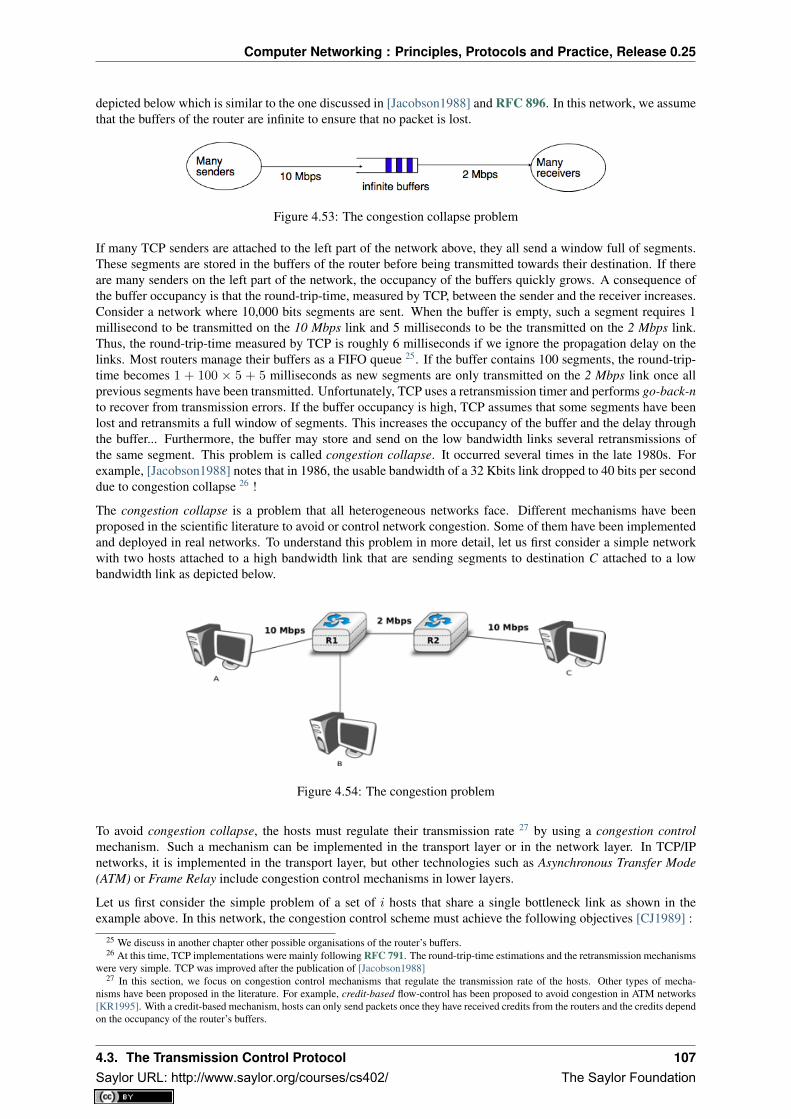
Computer Networking : Principles, Protocols and Practice, Release 0.25
depicted below which is similar to the one discussed in [Jacobson1988] and RFC 896. In this network, we assumethat the buffers of the router are infinite to ensure that no packet is lost.
Figure 4.53: The congestion collapse problem
If many TCP senders are attached to the left part of the network above, they all send a window full of segments.These segments are stored in the buffers of the router before being transmitted towards their destination. If thereare many senders on the left part of the network, the occupancy of the buffers quickly grows. A consequence ofthe buffer occupancy is that the round-trip-time, measured by TCP, between the sender and the receiver increases.Consider a network where 10,000 bits segments are sent. When the buffer is empty, such a segment requires 1millisecond to be transmitted on the 10 Mbps link and 5 milliseconds to be the transmitted on the 2 Mbps link.Thus, the round-trip-time measured by TCP is roughly 6 milliseconds if we ignore the propagation delay on thelinks. Most routers manage their buffers as a FIFO queue 25. If the buffer contains 100 segments, the round-trip-time becomes 1 + 100 × 5 + 5 milliseconds as new segments are only transmitted on the 2 Mbps link once allprevious segments have been transmitted. Unfortunately, TCP uses a retransmission timer and performs go-back-nto recover from transmission errors. If the buffer occupancy is high, TCP assumes that some segments have beenlost and retransmits a full window of segments. This increases the occupancy of the buffer and the delay throughthe buffer... Furthermore, the buffer may store and send on the low bandwidth links several retransmissions ofthe same segment. This problem is called congestion collapse. It occurred several times in the late 1980s. Forexample, [Jacobson1988] notes that in 1986, the usable bandwidth of a 32 Kbits link dropped to 40 bits per seconddue to congestion collapse 26 !
The congestion collapse is a problem that all heterogeneous networks face. Different mechanisms have beenproposed in the scientific literature to avoid or control network congestion. Some of them have been implementedand deployed in real networks. To understand this problem in more detail, let us first consider a simple networkwith two hosts attached to a high bandwidth link that are sending segments to destination C attached to a lowbandwidth link as depicted below.
Figure 4.54: The congestion problem
To avoid congestion collapse, the hosts must regulate their transmission rate 27 by using a congestion controlmechanism. Such a mechanism can be implemented in the transport layer or in the network layer. In TCP/IPnetworks, it is implemented in the transport layer, but other technologies such as Asynchronous Transfer Mode(ATM) or Frame Relay include congestion control mechanisms in lower layers.
Let us first consider the simple problem of a set of i hosts that share a single bottleneck link as shown in theexample above. In this network, the congestion control scheme must achieve the following objectives [CJ1989] :
25 We discuss in another chapter other possible organisations of the router’s buffers.26 At this time, TCP implementations were mainly following RFC 791. The round-trip-time estimations and the retransmission mechanisms
were very simple. TCP was improved after the publication of [Jacobson1988]27 In this section, we focus on congestion control mechanisms that regulate the transmission rate of the hosts. Other types of mecha-
nisms have been proposed in the literature. For example, credit-based flow-control has been proposed to avoid congestion in ATM networks[KR1995]. With a credit-based mechanism, hosts can only send packets once they have received credits from the routers and the credits dependon the occupancy of the router’s buffers.
4.3. The Transmission Control Protocol 107Saylor URL: http://www.saylor.org/courses/cs402/ The Saylor Foundation

Computer Networking : Principles, Protocols and Practice, Release 0.25
1. The congestion control scheme must avoid congestion. In practice, this means that the bottle-neck link cannot be overloaded. If ri(t) is the transmission rate allocated to host i at time t andR the bandwidth of the bottleneck link, then the congestion control scheme should ensure that,on average, ∀t
∑ri(t) ≤ R.
2. The congestion control scheme must be efficient. The bottleneck link is usually both a sharedand an expensive resource. Usually, bottleneck links are wide area links that are much moreexpensive to upgrade than the local area networks. The congestion control scheme should ensurethat such links are efficiently used. Mathematically, the control scheme should ensure that∀t
∑ri(t) ≈ R.
3. The congestion control scheme should be fair. Most congestion schemes aim at achieving max-min fairness. An allocation of transmission rates to sources is said to be max-min fair if :
• no link in the network is congested
• the rate allocated to source j cannot be increased without decreasing the rate allocated to asource i whose allocation is smaller than the rate allocated to source j [Leboudec2008] .
Depending on the network, a max-min fair allocation may not always exist. In practice, max-min fairness is anideal objective that cannot necessarily be achieved. When there is a single bottleneck link as in the example above,max-min fairness implies that each source should be allocated the same transmission rate.
To visualise the different rate allocations, it is useful to consider the graph shown below. In this graph, we ploton the x-axis (resp. y-axis) the rate allocated to host B (resp. A). A point in the graph (rB , rA) corresponds to apossible allocation of the transmission rates. Since there is a 2 Mbps bottleneck link in this network, the graphcan be divided into two regions. The lower left part of the graph contains all allocations (rB , rA) such that thebottleneck link is not congested (rA + rB < 2). The right border of this region is the efficiency line, i.e. the setof allocations that completely utilise the bottleneck link (rA + rB = 2). Finally, the fairness line is the set of fairallocations.
Figure 4.55: Possible allocated transmission rates
As shown in the graph above, a rate allocation may be fair but not efficient (e.g. rA = 0.7, rB = 0.7), fair andefficient ( e.g. rA = 1, rB = 1) or efficient but not fair (e.g. rA = 1.5, rB = 0.5). Ideally, the allocation shouldbe both fair and efficient. Unfortunately, maintaining such an allocation with fluctuations in the number of flowsthat use the network is a challenging problem. Furthermore, there might be several thousands of TCP connectionsor more that pass through the same link 28.
To deal with these fluctuations in demand, which result in fluctuations in the available bandwidth, computernetworks use a congestion control scheme. This congestion control scheme should achieve the three objectiveslisted above. Some congestion control schemes rely on a close cooperation between the endhosts and the routers,while others are mainly implemented on the endhosts with limited support from the routers.
28 For example, the measurements performed in the Sprint network in 2004 reported more than 10k active TCP connections on a link, seehttps://research.sprintlabs.com/packstat/packetoverview.php. More recent information about backbone links may be obtained from caida ‘srealtime measurements, see e.g. http://www.caida.org/data/realtime/passive/
108 Chapter 4. The transport layerSaylor URL: http://www.saylor.org/courses/cs402/ The Saylor Foundation

Computer Networking : Principles, Protocols and Practice, Release 0.25
A congestion control scheme can be modelled as an algorithm that adapts the transmission rate (ri(t)) of host ibased on the feedback received from the network. Different types of feedbacks are possible. The simplest schemeis a binary feedback [CJ1989] [Jacobson1988] where the hosts simply learn whether the network is congested ornot. Some congestion control schemes allow the network to regularly send an allocated transmission rate in Mbpsto each host [BF1995].
Let us focus on the binary feedback scheme which is the most widely used today. Intuitively, the congestioncontrol scheme should decrease the transmission rate of a host when congestion has been detected in the network,in order to avoid congestion collapse. Furthermore, the hosts should increase their transmission rate when thenetwork is not congested. Otherwise, the hosts would not be able to efficiently utilise the network. The rateallocated to each host fluctuates with time, depending on the feedback received from the network. The figurebelow illustrates the evolution of the transmission rates allocated to two hosts in our simple network. Initially, twohosts have a low allocation, but this is not efficient. The allocations increase until the network becomes congested.At this point, the hosts decrease their transmission rate to avoid congestion collapse. If the congestion controlscheme works well, after some time the allocations should become both fair and efficient.
Figure 4.56: Evolution of the transmission rates
Various types of rate adaption algorithms are possible. Dah Ming Chiu and Raj Jain have analysed, in [CJ1989],different types of algorithms that can be used by a source to adapt its transmission rate to the feedback receivedfrom the network. Intuitively, such a rate adaptation algorithm increases the transmission rate when the networkis not congested (ensure that the network is efficiently used) and decrease the transmission rate when the networkis congested (to avoid congestion collapse).
The simplest form of feedback that the network can send to a source is a binary feedback (the network is congestedor not congested). In this case, a linear rate adaptation algorithm can be expressed as :
• rate(t+ 1) = αC + βCrate(t) when the network is congested
• rate(t+ 1) = αN + βNrate(t) when the network is not congested
With a linear adaption algorithm, αC , αN , βC and βN are constants. The analysis of [CJ1989] shows that tobe fair and efficient, such a binary rate adaption mechanism must rely on Additive Increase and MultiplicativeDecrease. When the network is not congested, the hosts should slowly increase their transmission rate (βN =1 and αN > 0). When the network is congested, the hosts must multiplicatively decrease their transmission rate(βC < 1 and αC = 0). Such an AIMD rate adaptation algorithm can be implemented by the pseudo-code below
# Additive Increase Multiplicative Decreaseif congestion :
rate=rate*betaC # multiplicative decrease, betaC<1else
rate=rate+alphaN # additive increase, v0>0
Note: Which binary feedback ?
Two types of binary feedback are possible in computer networks. A first solution is to rely on implicit feedback.This is the solution chosen for TCP. TCP’s congestion control scheme [Jacobson1988] does not require any coop-eration from the router. It only assumes that they use buffers and that they discard packets when there is congestion.
4.3. The Transmission Control Protocol 109Saylor URL: http://www.saylor.org/courses/cs402/ The Saylor Foundation

Computer Networking : Principles, Protocols and Practice, Release 0.25
TCP uses the segment losses as an indication of congestion. When there are no losses, the network is assumed tobe not congested. This implies that congestion is the main cause of packet losses. This is true in wired networks,but unfortunately not always true in wireless networks. Another solution is to rely on explicit feedback. Thisis the solution proposed in the DECBit congestion control scheme [RJ1995] and used in Frame Relay and ATMnetworks. This explicit feedback can be implemented in two ways. A first solution would be to define a specialmessage that could be sent by routers to hosts when they are congested. Unfortunately, generating such messagesmay increase the amount of congestion in the network. Such a congestion indication packet is thus discouragedRFC 1812. A better approach is to allow the intermediate routers to indicate, in the packets that they forward,their current congestion status. Binary feedback can be encoded by using one bit in the packet header. With such ascheme, congested routers set a special bit in the packets that they forward while non-congested routers leave thisbit unmodified. The destination host returns the congestion status of the network in the acknowledgements that itsends. Details about such a solution in IP networks may be found in RFC 3168. Unfortunately, as of this writing,this solution is still not deployed despite its potential benefits.
The TCP congestion control scheme was initially proposed by Van Jacobson in [Jacobson1988]. The currentspecification may be found in RFC 5681. TCP relies on Additive Increase and Multiplicative Decrease (AIMD).To implement AIMD, a TCP host must be able to control its transmission rate. A first approach would be to usetimers and adjust their expiration times in function of the rate imposed by AIMD. Unfortunately, maintaining suchtimers for a large number of TCP connections can be difficult. Instead, Van Jacobson noted that the rate of TCPcongestion can be artificially controlled by constraining its sending window. A TCP connection cannot send datafaster than window
rtt wherewindow is the maximum between the host’s sending window and the window advertisedby the receiver.
TCP’s congestion control scheme is based on a congestion window. The current value of the congestion window(cwnd) is stored in the TCB of each TCP connection and the window that can be used by the sender is constrainedby min(cwnd, rwin, swin) where swin is the current sending window and rwin the last received receive win-dow. The Additive Increase part of the TCP congestion control increments the congestion window by MSS bytesevery round-trip-time. In the TCP literature, this phase is often called the congestion avoidance phase. The Mul-tiplicative Decrease part of the TCP congestion control divides the current value of the congestion window oncecongestion has been detected.
When a TCP connection begins, the sending host does not know whether the part of the network that it usesto reach the destination is congested or not. To avoid causing too much congestion, it must start with a smallcongestion window. [Jacobson1988] recommends an initial window of MSS bytes. As the additive increase partof the TCP congestion control scheme increments the congestion window by MSS bytes every round-trip-time,the TCP connection may have to wait many round-trip-times before being able to efficiently use the availablebandwidth. This is especially important in environments where the bandwidth × rtt product is high. To avoidwaiting too many round-trip-times before reaching a congestion window that is large enough to efficiently utilisethe network, the TCP congestion control scheme includes the slow-start algorithm. The objective of the TCPslow-start is to quickly reach an acceptable value for the cwnd. During slow-start, the congestion window isdoubled every round-trip-time. The slow-start algorithm uses an additional variable in the TCB : sshtresh (slow-start threshold). The ssthresh is an estimation of the last value of the cwnd that did not cause congestion. It isinitialised at the sending window and is updated after each congestion event.
In practice, a TCP implementation considers the network to be congested once its needs to retransmit a segment.The TCP congestion control scheme distinguishes between two types of congestion :
• mild congestion. TCP considers that the network is lightly congested if it receives three duplicate acknowl-edgements and performs a fast retransmit. If the fast retransmit is successful, this implies that only onesegment has been lost. In this case, TCP performs multiplicative decrease and the congestion window isdivided by 2. The slow-start threshold is set to the new value of the congestion window.
• severe congestion. TCP considers that the network is severely congested when its retransmission timerexpires. In this case, TCP retransmits the first segment, sets the slow-start threshold to 50% of the congestionwindow. The congestion window is reset to its initial value and TCP performs a slow-start.
The figure below illustrates the evolution of the congestion window when there is severe congestion. At thebeginning of the connection, the sender performs slow-start until the first segments are lost and the retransmissiontimer expires. At this time, the ssthresh is set to half of the current congestion window and the congestion windowis reset at one segment. The lost segments are retransmitted as the sender again performs slow-start until the
110 Chapter 4. The transport layerSaylor URL: http://www.saylor.org/courses/cs402/ The Saylor Foundation

Computer Networking : Principles, Protocols and Practice, Release 0.25
congestion window reaches the sshtresh. It then switches to congestion avoidance and the congestion windowincreases linearly until segments are lost and the retransmission timer expires ...
Figure 4.57: Evaluation of the TCP congestion window with severe congestion
The figure below illustrates the evolution of the congestion window when the network is lightly congested andall lost segments can be retransmitted using fast retransmit. The sender begins with a slow-start. A segment islost but successfully retransmitted by a fast retransmit. The congestion window is divided by 2 and the senderimmediately enters congestion avoidance as this was a mild congestion.
Figure 4.58: Evaluation of the TCP congestion window when the network is lightly congested
Most TCP implementations update the congestion window when they receive an acknowledgement. If we assumethat the receiver acknowledges each received segment and the sender only sends MSS sized segments, the TCPcongestion control scheme can be implemented using the simplified pseudo-code 29 below
# Initialisationcwnd = MSS;ssthresh= swin;
# Ack arrivalif tcp.ack > snd.una : # new ack, no congestion
if cwnd < ssthresh :# slow-start : increase quickly cwnd# double cwnd every rttcwnd = cwnd + MSS
else:# congestion avoidance : increase slowly cwnd# increase cwnd by one mss every rttcwnd = cwnd+ mss*(mss/cwnd)
else: # duplicate or old ackif tcp.ack==snd.una: # duplicate acknowledgement
dupacks++if dupacks==3:
29 In this pseudo-code, we assume that TCP uses unlimited sequence and acknowledgement numbers. Furthermore, we do not detail howthe cwnd is adjusted after the retransmission of the lost segment by fast retransmit. Additional details may be found in RFC 5681.
4.3. The Transmission Control Protocol 111Saylor URL: http://www.saylor.org/courses/cs402/ The Saylor Foundation

Computer Networking : Principles, Protocols and Practice, Release 0.25
retransmitsegment(snd.una)ssthresh=max(cwnd/2,2*MSS)cwnd=ssthresh
else:dupacks=0# ack for old segment, ignored
Expiration of the retransmission timer:send(snd.una) # retransmit first lost segmentsshtresh=max(cwnd/2,2*MSS)cwnd=MSS
Furthermore when a TCP connection has been idle for more than its current retransmission timer, it should reset itscongestion window to the congestion window size that it uses when the connection begins, as it no longer knowsthe current congestion state of the network.
Note: Initial congestion window
The original TCP congestion control mechanism proposed in [Jacobson1988] recommended that each TCP con-nection should begin by setting cwnd = MSS. However, in today’s higher bandwidth networks, using such asmall initial congestion window severely affects the performance for short TCP connections, such as those usedby web servers. Since the publication of RFC 3390, TCP hosts are allowed to use an initial congestion windowof about 4 KBytes, which corresponds to 3 segments in many environments.
Thanks to its congestion control scheme, TCP adapts its transmission rate to the losses that occur in the net-work. Intuitively, the TCP transmission rate decreases when the percentage of losses increases. Researchers haveproposed detailed models that allow the prediction of the throughput of a TCP connection when losses occur[MSMO1997] . To have some intuition about the factors that affect the performance of TCP, let us consider avery simple model. Its assumptions are not completely realistic, but it gives us good intuition without requiringcomplex mathematics.
This model considers a hypothetical TCP connection that suffers from equally spaced segment losses. If p is thesegment loss ratio, then the TCP connection successfully transfers 1
p − 1 segments and the next segment is lost.If we ignore the slow-start at the beginning of the connection, TCP in this environment is always in congestionavoidance as there are only isolated losses that can be recovered by using fast retransmit. The evolution of thecongestion window is thus as shown in the figure below. Note the that x-axis of this figure represents time measuredin units of one round-trip-time, which is supposed to be constant in the model, and the y-axis represents the sizeof the congestion window measured in MSS-sized segments.
Figure 4.59: Evolution of the congestion window with regular losses
As the losses are equally spaced, the congestion window always starts at some value (W2 ), and is incremented by
one MSS every round-trip-time until it reaches twice this value (W). At this point, a segment is retransmitted andthe cycle starts again. If the congestion window is measured in MSS-sized segments, a cycle lasts W
2 round-trip-times. The bandwidth of the TCP connection is the number of bytes that have been transmitted during a givenperiod of time. During a cycle, the number of segments that are sent on the TCP connection is equal to the area ofthe yellow trapeze in the figure. Its area is thus :
area = (W2 )2 + 1
2 × (W2 )2 = 3×W 2
8
112 Chapter 4. The transport layerSaylor URL: http://www.saylor.org/courses/cs402/ The Saylor Foundation

Computer Networking : Principles, Protocols and Practice, Release 0.25
However, given the regular losses that we consider, the number of segments that are sent between two losses (i.e.during a cycle) is by definition equal to 1
p . Thus, W =√
83×p = k√
p . The throughput (in bytes per second) of theTCP connection is equal to the number of segments transmitted divided by the duration of the cycle :
Throughput = area×MSStime =
3×W28
W2 ×rtt
or, after having eliminated W, Throughput =√
32 ×
MSSrtt×√p
More detailed models and the analysis of simulations have shown that a first order model of the TCP throughputwhen losses occur was Throughput ≈ k×MSS
rtt×√p . This is an important result which shows that :
• TCP connections with a small round-trip-time can achieve a higher throughput than TCP connections havinga longer round-trip-time when losses occur. This implies that the TCP congestion control scheme is notcompletely fair since it favors the connections that have the shorter round-trip-time
• TCP connections that use a large MSS can achieve a higher throughput that the TCP connections that usea shorter MSS. This creates another source of unfairness between TCP connections. However, it should benoted that today most hosts are using almost the same MSS, roughly 1460 bytes.
In general, the maximum throughput that can be achieved by a TCP connection depends on its maximum windowsize and the round-trip-time if there are no losses. If there are losses, it depends on the MSS, the round-trip-timeand the loss ratio.
Throughput < min(windowrtt , k×MSS
rtt×√p )
Note: The TCP congestion control zoo
The first TCP congestion control scheme was proposed by Van Jacobson in [Jacobson1988]. In addition to writingthe scientific paper, Van Jacobson also implemented the slow-start and congestion avoidance schemes in release4.3 Tahoe of the BSD Unix distributed by the University of Berkeley. Later, he improved the congestion controlby adding the fast retransmit and the fast recovery mechanisms in the Reno release of 4.3 BSD Unix. Sincethen, many researchers have proposed, simulated and implemented modifications to the TCP congestion controlscheme. Some of these modifications are still used today, e.g. :
• NewReno ( RFC 3782), which was proposed as an improvement of the fast recovery mechanism in the Renoimplementation
• TCP Vegas, which uses changes in the round-trip-time to estimate congestion in order to avoid it [BOP1994]
• CUBIC, which was designed for high bandwidth links and is the default congestion control scheme in theLinux 2.6.19 kernel [HRX2008]
• Compound TCP, which was designed for high bandwidth links is the default congestion control scheme inseveral Microsoft operating systems [STBT2009]
A search of the scientific literature will probably reveal more than 100 different variants of the TCP congestioncontrol scheme. Most of them have only been evaluated by simulations. However, the TCP implementation inthe recent Linux kernels supports several congestion control schemes and new ones can be easily added. We canexpect that new TCP congestion control schemes will always continue to appear.
4.4 Summary
In this chapter, we have studied the transport layer. This layer provides two types of services to the applicationlayer. The unreliable connectionless service is the simplest service offered to applications. On the Internet, this isthe service offered by UDP. However, most applications prefer to use a reliable and connection-oriented transportservice. We have shown that providing this service was much more complex than providing an unreliable serviceas the transport layer needs to recover from the errors that occur in the network layer. For this, transport layerprotocols rely on several mechanisms. First, they use a handshake mechanism, such as the three-way handshakemechanism, to correctly establish a transport connection. Once the connection has been established, transportentities exchange segments. Each segment contains a sequence number, and the transport layer uses acknowl-edgements to confirm the segments that have been correctly received. In addition, timers are used to recover fromsegment losses and sliding windows are used to avoid overflowing the buffers of the transport entities. Finally,
4.4. Summary 113Saylor URL: http://www.saylor.org/courses/cs402/ The Saylor Foundation

Computer Networking : Principles, Protocols and Practice, Release 0.25
we explained how a transport connection can be safely released. We then discussed the mechanisms that are usedin TCP, the reliable transport protocol, used by most applications on the Internet. Most notably, we described thecongestion control mechanism that has been included in TCP since the late 1980s and explained how the reliabilitymechanisms used by TCP have been tuned over the years.
4.5 Exercises
This section is divided in two parts. The first part contains exercises on the principles of transport protocols,including TCP. The second part contains programming challenges packet analysis tools to observe the behaviourof transport protocols.
4.5.1 Principles
1. Consider the Alternating Bit Protocol as described in this chapter
• How does the protocol recover from the loss of a data segment ?
• How does the protocol recovers from the loss of an acknowledgement ?
2. A student proposed to optimise the Alternating Bit Protocol by adding a negative acknowledgment, i.e. thereceiver sends a NAK control segment when it receives a corrupted data segment. What kind of informationshould be placed in this control segment and how should the sender react when receiving such a NAK ?
3. Transport protocols rely on different types of checksums to verify whether segments have been affected bytransmission errors. The most frequently used checksums are :
• the Internet checksum used by UDP, TCP and other Internet protocolswhich is defined in RFC 1071 and implemented in various modules, e.g.http://ilab.cs.byu.edu/cs460/code/ftp/ichecksum.py for a python implementation
• the 16 bits or the 32 bits Cyclical Redundancy Checks (CRC) that are often used on disks, inzip archives and in datalink layer protocols. See http://docs.python.org/library/binascii.html fora python module that contains the 32 bits CRC
• the Alder checksum defined in RFC 2920 for the SCTP protocol but replaced by a CRC laterRFC 3309
• the Fletcher checksum [Fletcher1982], see http://drdobbs.com/database/184408761 for imple-mentation details
By using your knowledge of the Internet checksum, can you find a transmission error that will not bedetected by the Internet checksum ?
4. The CRCs are efficient error detection codes that are able to detect :
• all errors that affect an odd number of bits
• all errors that affect a sequence of bits which is shorter than the length of the CRC
Carry experiments with one implementation of CRC-32 to verify that this is indeed the case.
5. Checksums and CRCs should not be confused with secure hash functions such as MD5 defined in RFC1321 or SHA-1 described in RFC 4634. Secure hash functions are used to ensure that files or sometimespackets/segments have not been modified. Secure hash functions aim at detecting malicious changes whilechecksums and CRCs only detect random transmission errors. Perform some experiments with hash func-tions such as those defined in the http://docs.python.org/library/hashlib.html python hashlib module to verifythat this is indeed the case.
6. A version of the Alternating Bit Protocol supporting variable length segments uses a header that containsthe following fields :
• a number (0 or 1)
• a length field that indicates the length of the data
114 Chapter 4. The transport layerSaylor URL: http://www.saylor.org/courses/cs402/ The Saylor Foundation

Computer Networking : Principles, Protocols and Practice, Release 0.25
• a CRC
To speedup the transmission of the segments, a student proposes to compute the CRC over the datapart of the segment but not over the header. What do you think of this optimisation ?
7. On Unix hosts, the ping(8) command can be used to measure the round-trip-time to send and receivepackets from a remote host. Use ping(8) to measure the round-trip to a remote host. Chose a remotedestination which is far from your current location, e.g. a small web server in a distant country. There areimplementations of ping in various languages, see e.g. http://pypi.python.org/pypi/ping/0.2 for a pythonimplementation of ‘’ping’‘
8. How would you set the retransmission timer if you were implementing the Alternating Bit Protocol toexchange files with a server such as the one that you measured above ?
9. What are the factors that affect the performance of the Alternating Bit Protocol ?
10. Links are often considered as symmetrical, i.e. they offer the same bandwidth in both directions. Sym-metrical links are widely used in Local Area Networks and in the core of the Internet, but there are manyasymmetrical link technologies. The most common example are the various types of ADSL and CATVtechnologies. Consider an implementation of the Alternating Bit Protocol that is used between two hoststhat are directly connected by using an asymmetric link. Assume that a host is sending segments containing10 bytes of control information and 90 bytes of data and that the acknowledgements are 10 bytes long. Ifthe round-trip-time is negligible, what is the minimum bandwidth required on the return link to ensure thatthe transmission of acknowledgements is not a bottleneck ?
11. Derive a mathematical expression that provides the goodput achieved by the Alternating Bit Protocol as-suming that :
• Each segment contains D bytes of data and c bytes of control information
• Each acknowledgement contains c bytes of control information
• The bandwidth of the two directions of the link is set to B bits per second
• The delay between the two hosts is s seconds in both directions
The goodput is defined as the amount of SDUs (measured in bytes) that is successfully transferredduring a period of time
12. Consider an Alternating Bit Protocol that is used over a link that suffers from deterministic errors. Whenthe error ratio is set to 1
p , this means that p − 1 bits are transmitted correctly and the pth bit is corrupted.Discuss the factors that affect the performance of the Alternating Bit Protocol over such a link.
13. Amazon provides the S3 storage service where companies and researchers can store lots of information andperform computations on the stored information. Amazon allows users to send files through the Internet, butalso by sending hard-disks. Assume that a 1 Terabyte hard-disk can be delivered within 24 hours to Amazonby courier service. What is the minimum bandwidth required to match the bandwidth of this courier service?
14. Several large data centers operators (e.g. Microsoft and google) have announced that they install serversas containers with each container hosting up to 2000 servers. Assuming a container with 2000 servers andeach storing 500 GBytes of data, what is the time required to move all the data stored in one container overone 10 Gbps link ? What is the bandwidth of a truck that needs 10 hours to move one container from onedata center to another.
15. What are the techniques used by a go-back-n sender to recover from :
• transmission errors
• losses of data segments
• losses of acknowledgements
16. Consider a b bits per second link between two hosts that has a propagation delay of t seconds. Derive aformula that computes the time elapsed between the transmission of the first bit of a d bytes segment froma sending host and the reception of the last bit of this segment on the receiving host.
4.5. Exercises 115Saylor URL: http://www.saylor.org/courses/cs402/ The Saylor Foundation

Computer Networking : Principles, Protocols and Practice, Release 0.25
17. Consider a go-back-n sender and a go-back receiver that are directly connected with a 10 Mbps link thathas a propagation delay of 100 milliseconds. Assume that the retransmission timer is set to three seconds.If the window has a length of 4 segments, draw a time-sequence diagram showing the transmission of 10segments (each segment contains 10000 bits):
• when there are no losses
• when the third and seventh segments are lost
• when the second, fourth, sixth, eighth, ... acknowledgements are lost
• when the third and fourth data segments are reordered (i.e. the fourth arrives before the third)
18. Same question when using selective repeat instead of go-back-n. Note that the answer is not necessarily thesame.
19. Consider two high-end servers connected back-to-back by using a 10 Gbps interface. If the delay betweenthe two servers is one millisecond, what is the throughput that can be achieved by a transport protocol thatis using 10,000 bits segments and a window of
• one segment
• ten segments
• hundred segments
20. Consider two servers are directly connected by using a b bits per second link with a round-trip-time of rseconds. The two servers are using a transport protocol that sends segments containing s bytes and acknowl-edgements composed of a bytes. Can you derive a formula that computes the smallest window (measuredin segments) that is required to ensure that the servers will be able to completely utilise the link ?
21. Same question as above if the two servers are connected through an asymmetrical link that transmits bu bitsper second in the direction used to send data segments and bd bits per second in the direction used to sendacknowledgements.
22. The Trivial File Transfer Protocol is a very simple file transfer protocol that is often used by disk-less hostswhen booting from a server. Read the TFTP specification in RFC 1350 and explain how TFTP recoversfrom transmission errors and losses.
23. Is it possible for a go-back-n receiver to inter-operate with a selective-repeat sender ? Justify your answer.
24. Is it possible for a selective-repeat receiver to inter-operate with a go-back-n sender ? Justify your answer.
25. The go-back-n and selective repeat mechanisms that are described in the book exclusively rely on cumu-lative acknowledgements. This implies that a receiver always returns to the sender information about thelast segment that was received in-sequence. If there are frequent losses or reordering, a selective repeatreceiver could return several times the same cumulative acknowledgment. Can you think of other types ofacknowledgements that could be used by a selective repeat receiver to provide additional information aboutthe out-of-sequence segments that it has received. Design such acknowledgements and explain how thesender should react upon reception of this information.
26. The goodput achieved by a transport protocol is usually defined as the number of application layer bytesthat are exchanged per unit of time. What are the factors that can influence the goodput achieved by a giventransport protocol ?
27. When used with IPv4, Transmission Control Protocol (TCP) attaches 40 bytes of control information toeach segment sent. Assuming an infinite window and no losses nor transmission errors, derive a formulathat computes the maximum TCP goodput in function of the size of the segments that are sent.
28. A go-back-n sender uses a window size encoded in a n bits field. How many segments can it send withoutreceiving an acknowledgement ?
29. Consider the following situation. A go-back-n receiver has sent a full window of data segments. All thesegments have been received correctly and in-order by the receiver, but all the returned acknowledgementshave been lost. Show by using a time sequence diagram (e.g. by considering a window of four segments)what happens in this case. Can you fix the problem on the go-back-n sender ?
116 Chapter 4. The transport layerSaylor URL: http://www.saylor.org/courses/cs402/ The Saylor Foundation

Computer Networking : Principles, Protocols and Practice, Release 0.25
30. Same question as above, but assume now that both the sender and the receiver implement selective repeat.Note the the answer will be different from the above question.
31. Consider a transport that supports window of one hundred 1250 Bytes segments. What is the maximumbandwidth that this protocol can achieve if the round-trip-time is set to one second ? What happens if,instead of advertising a window of one hundred segments, the receiver decides to advertise a window of 10segments ?
32. Explain under which circumstances a transport entity could advertise a window of 0 segments ?
33. To understand the operation of the TCP congestion control mechanism, it is useful to draw some timesequence diagrams. Let us consider a simple scenario of a web client connected to the Internet that wishesto retrieve a simple web page from a remote web server. For simplicity, we will assume that the delaybetween the client and the server is 0.5 seconds and that the packet transmission times on the client andthe servers are negligible (e.g. they are both connected to a 1 Gbps network). We will also assume that theclient and the server use 1 KBytes segments.
1. Compute the time required to open a TCP connection, send an HTTP request and retrieve a 16 KBytes webpage. This page size is typical of the results returned by search engines like google_ or bing. An importantfactor in this delay is the initial size of the TCP congestion window on the server. Assume first that the initialwindow is set to 1 segment as defined in RFC 2001, 4 KBytes (i.e. 4 segments in this case) as proposed inRFC 3390 or 16 KBytes as proposed in a recent paper.
2. Perform the same analysis with an initial window of one segment is the third segment sent by the server islost and the retransmission timeout is fixed and set to 2 seconds.
3. Same question as above but assume now that the 6th segment is lost.
4. Same question as above, but consider now the loss of the second and seventh acknowledgements sent by theclient.
5. Does the analysis above changes if the initial window is set to 16 KBytes instead of one segment ?
34. Several MBytes have been sent on a TCP connection and it becomes idle for several minutes. Discuss whichvalues should be used for the congestion window, slow start threshold and retransmission timers.
35. To operate reliably, a transport protocol that uses Go-back-n (resp. selective repeat) cannot use a windowthat is larger than 2n − 1 (resp. 2n−1) segments. Does this limitation affects TCP ? Explain your answer.
36. Consider the simple network shown in the figure below. In this network, the router between the client andthe server can only store on each outgoing interface one packet in addition to the packet that it is currentlytransmitting. It discards all the packets that arrive while its buffer is full. Assuming that you can neglectthe transmission time of acknowledgements and that the server uses an initial window of one segment andhas a retransmission timer set to 500 milliseconds, what is the time required to transmit 10 segments fromthe client to the server. Does the performance increases if the server uses an initial window of 16 segmentsinstead ?
Figure 4.60: Simple network
37. The figure below describes the evolution of the congestion window of a TCP connection. Can you find thereasons for the three events that are marked in the figure ?
38. The figure below describes the evolution of the congestion window of a TCP connection. Can you find thereasons for the three events that are marked in the figure ?
4.5. Exercises 117Saylor URL: http://www.saylor.org/courses/cs402/ The Saylor Foundation

Computer Networking : Principles, Protocols and Practice, Release 0.25
Figure 4.61: Evolution of the congestion window
Figure 4.62: Evolution of the congestion window
39. A web server serves mainly HTML pages that fit inside 10 TCP segments. Assuming that the transmissiontime of each segment can be neglected, compute the total transfer time of such a page (in round-trip-times)assuming that :
• the TCP stack uses an initial window size of 1 segment
• the TCP stack uses an initial window size of three segments
40. RFC 3168 defines mechanism that allow routers to mark packets by setting one bit in the packet header whenthey are congested. When a TCP destination receives such a marking in a packet, it returns the congestionmarking to the source that reacts by halving its congestion window and performs congestion avoidance.Consider a TCP connection where the fourth data segment experiences congestion. Compare the delay totransmit 8 segments in a network where routers discards packets during congestion and a network whererouters mark packets during congestion.
4.5.2 Practice
1. The socket interface allows you to use the UDP protocol on a Unix host. UDP provides a connectionlessunreliable service that in theory allows you to send SDUs of up to 64 KBytes.
• Implement a small UDP client and a small UDP server (in python, you can start from the example providedin http://docs.python.org/library/socket.html but you can also use C or java )
• run the client and the servers on different workstations to determine experimentally the largest SDU thatis supported by your language and OS. If possible, use different languages and Operating Systems in eachgroup.
2. By using the socket interface, implement on top of the connectionless unreliable service provided by UDPa simple client that sends the following message shown in the figure below.
In this message, the bit flags should be set to 01010011b, the value of the 16 bits field must bethe square root of the value contained in the 32 bits field, the character string must be an ASCIIrepresentation (without any trailing 0) of the number contained in the 32 bits character field. The last16 bits of the message contain an Internet checksum that has been computed over the entire message.
Upon reception of a message, the server verifies that :
118 Chapter 4. The transport layerSaylor URL: http://www.saylor.org/courses/cs402/ The Saylor Foundation

Computer Networking : Principles, Protocols and Practice, Release 0.25
• the flag has the correct value
• the 32 bits integer is the square of the 16 bits integer
• the character string is an ASCII representation of the 32 bits integer
• the Internet checksum is correct
If the verification succeeds, the server returns a SDU containing 11111111b. Otherwise it returns01010101b
Your implementation must be able to run on both low endian and big endian machines. If you haveaccess to different types of machines (e.g. x86 laptops and SPARC servers), try to run your imple-mentation on both types of machines.
Figure 4.63: Simple SDU format
3. The socket library is also used to develop applications above the reliable bytestream service provided byTCP. We have installed on the cnp3.info.ucl.ac.be server a simple server that provides a simple client-serverservice. The service operates as follows :
• the server listens on port 62141 for a TCP connection
• upon the establishment of a TCP connection, the server sends an integer by using the followingTLV format :
– the first two bits indicate the type of information (01 for ASCII, 10 for boolean)
– the next six bits indicate the length of the information (in bytes)
– An ASCII TLV has a variable length and the next bytes contain one ASCII character perbyte. A boolean TLV has a length of one byte. The byte is set to 00000000b for true and00000001b for false.
• the client replies by sending the received integer encoded as a 32 bits integer in network byteorder
• the server returns a TLV containing true if the integer was correct and a TLV containing falseotherwise and closes the TCP connection
Implement a client to interact with this server in C, Java or python.
4. It is now time to implement a small transport protocol. The protocol uses a sliding window to transmit morethan one segment without being forced to wait for an acknowledgment. Your implementation must supportvariable size sliding window as the other end of the flow can send its maximum window size. The windowsize is encoded as a three bits unsigned integer.
The protocol identifies the DATA segments by using sequence numbers. The sequence number ofthe first segment must be 0. It is incremented by one for each new segment. The receiver mustacknowledge the delivered segments by sending an ACK segment. The sequence number field in theACK segment always contains the sequence number of the next expected in-sequence segment at thereceiver. The flow of data is unidirectional, meaning that the sender only sends DATA segments andthe receiver only sends ACK segments.
To deal with segments losses, the protocol must implement a recovery technique such as go-back-n orselective repeat and use retransmission timers. You can select the technique that best suite your needsand start from a simple technique that you improve later.
4.5. Exercises 119Saylor URL: http://www.saylor.org/courses/cs402/ The Saylor Foundation

Computer Networking : Principles, Protocols and Practice, Release 0.25
Figure 4.64: Segment format
This segment format contains the following fields :
• Type: segment type
– 0x1 DATA segment.
– 0x2 ACK segment
• WIN: the size of the current window (an integer encoded as a 3 bits field). In DATA segments,this field indicates the size of the sending window of the sender. In ACK segments, this fieldindicates the current value of the receiving window.
• Sequence: Sequence number (8 bits unsigned integer), starts at 0. The sequence number isincremented by 1 for each new DATA segment sent by the sender. Inside an ACK segment, thesequence field carries the sequence number of the next in-sequence segment that is expected bythe receiver.
• Length: length of the payload in multiple of one byte. All DATA segments contain a payloadwith 512 bytes of data, except the last DATA segment of a transfer that can be shorter. Thereception of a DATA segment whose length is different than 512 indicates the end of the datatransit.
• Payload: the data to send
The client and the server exchange UDP datagrams that contain the DATA and ACK segments. Theymust provide a command-line interface that allows to transmit one binary file and support the follow-ing parameters :
sender <destination_DNS_name> <destination_port_number> <window_size> <input_file>receiver <listening_port_number> <window_size> <output_file>
In order to test the reactions of your protocol against errors and losses, you you can use a randomnumber generator to probabilistically drop received segments and introduce random delays upon thearrival of a segment.
Packet trace analysis
When debugging networking problems or to analyse performance problems, it is sometimes useful to capture thesegments that are exchanged between two hosts and to analyse them.
Several packet trace analysis tools are available, either as commercial or open-source tools. These tools are ableto capture all the packets exchanged on a link. Of course, capturing packets require administrator privileges. Theycan also analyse the content of the captured packets and display information about them. The captured packetscan be stored in a file for offline analysis.
tcpdump is probably one of the most well known packet capture software. It is able to both capture packets anddisplay their content. tcpdump is a text-based tool that can display the value of the most important fields of thecaptured packets. Additional information about tcpdump may be found in tcpdump(1). The text below is anexample of the output of tcpdump for the first TCP segments exchanged on an scp transfer between two hosts.
21:05:56.230737 IP 192.168.1.101.54150 > 130.104.78.8.22: S 1385328972:1385328972(0) win 65535 <mss 1460,nop,wscale 3,nop,nop,timestamp 274527749 0,sackOK,eol>21:05:56.251468 IP 130.104.78.8.22 > 192.168.1.101.54150: S 3627767479:3627767479(0) ack 1385328973 win 49248 <nop,nop,timestamp 1212093352 274527749,mss 1452,nop,wscale 0,nop,nop,sackOK>21:05:56.251560 IP 192.168.1.101.54150 > 130.104.78.8.22: . ack 1 win 65535 <nop,nop,timestamp 274527749 1212093352>21:05:56.279137 IP 130.104.78.8.22 > 192.168.1.101.54150: P 1:21(20) ack 1 win 49248 <nop,nop,timestamp 1212093355 274527749>
120 Chapter 4. The transport layerSaylor URL: http://www.saylor.org/courses/cs402/ The Saylor Foundation

Computer Networking : Principles, Protocols and Practice, Release 0.25
21:05:56.279241 IP 192.168.1.101.54150 > 130.104.78.8.22: . ack 21 win 65535 <nop,nop,timestamp 274527749 1212093355>21:05:56.279534 IP 192.168.1.101.54150 > 130.104.78.8.22: P 1:22(21) ack 21 win 65535 <nop,nop,timestamp 274527749 1212093355>21:05:56.303527 IP 130.104.78.8.22 > 192.168.1.101.54150: . ack 22 win 49248 <nop,nop,timestamp 1212093357 274527749>21:05:56.303623 IP 192.168.1.101.54150 > 130.104.78.8.22: P 22:814(792) ack 21 win 65535 <nop,nop,timestamp 274527749 1212093357>
You can easily recognise in the output above the SYN segment containing the MSS, window scale, timestamp andsackOK options, the SYN+ACK segment whose wscale option indicates that the server uses window scaling forthis connection and then the first few segments exchanged on the connection.
wireshark is more recent than tcpdump. It evolved from the ethereal packet trace analysis software. It can be usedas a text tool like tcpdump. For a TCP connection, wireshark would provide almost the same output as tcpdump.The main advantage of wireshark is that it also includes a graphical user interface that allows to perform varioustypes of analysis on a packet trace.
Figure 4.65: Wireshark : default window
The wireshark window is divided in three parts. The top part of the window is a summary of the first packets fromthe trace. By clicking on one of the lines, you can show the detailed content of this packet in the middle part ofthe window. The middle of the window allows you to inspect all the fields of the captured packet. The bottom partof the window is the hexadecimal representation of the packet, with the field selected in the middle window beinghighlighted.
wireshark is very good at displaying packets, but it also contains several analysis tools that can be very useful.The first tool is Follow TCP stream. It is part of the Analyze menu and allows you to reassemble and display allthe payload exchanged during a TCP connection. This tool can be useful if you need to analyse for example thecommands exchanged during a SMTP session.
The second tool is the flow graph that is part of the Statistics menu. It provides a time sequence diagram of thepackets exchanged with some comments about the packet contents. See blow for an example.
Figure 4.66: Wireshark : flow graph
The third set of tools are the TCP stream graph tools that are part of the Statistics menu. These tools allow youto plot various types of information extracted from the segments exchanged during a TCP connection. A firstinteresting graph is the sequence number graph that shows the evolution of the sequence number field of thecaptured segments with time. This graph can be used to detect graphically retransmissions.
4.5. Exercises 121Saylor URL: http://www.saylor.org/courses/cs402/ The Saylor Foundation

Computer Networking : Principles, Protocols and Practice, Release 0.25
Figure 4.67: Wireshark : sequence number graph
A second interesting graph is the round-trip-time graph that shows the evolution of the round-trip-time in functionof time. This graph can be used to check whether the round-trip-time remains stable or not. Note that from apacket trace, wireshark can plot two round-trip-time graphs, One for the flow from the client to the server andthe other one. wireshark will plot the round-trip-time graph that corresponds to the selected packet in the topwireshark window.
Figure 4.68: Wireshark : round-trip-time graph
Emulating a network with netkit
Netkit is network emulator based on User Mode Linux. It allows to easily set up an emulated network of Linuxmachines, that can act as end-host or routers.
Note: Where can I find Netkit?
Netkit is available at http://www.netkit.org. Files can be downloaded fromhttp://wiki.netkit.org/index.php/Download_Official, and instructions for the installations are available here :http://wiki.netkit.org/download/netkit/INSTALL .
There are two ways to use Netkit : The manual way, and by using pre-configured labs. In the first case, youboot and control each machine individually, using the commands starting with a “v” (for virtual machine). In thesecond case, you can start a whole network in a single operation. The commands for controlling the lab start witha “l”. The man pages of those commands is available from http://wiki.netkit.org/man/man7/netkit.7.html
122 Chapter 4. The transport layerSaylor URL: http://www.saylor.org/courses/cs402/ The Saylor Foundation

Computer Networking : Principles, Protocols and Practice, Release 0.25
You must be careful not to forgot to stop your virtual machines and labs, using either vhalt or lhalt.
A netkit lab is simply a directory containing at least a configuration file called lab.conf, and one directory for eachvirtual machine. In the case the lab available on iCampus, the network is composed of two pcs, pc1 and pc2, bothof them being connected to a router r1. The lab.conf file contains the following lines :
pc1[0]=Apc2[0]=Br1[0]=Ar1[1]=B
This means that pc1 and r1 are connected to a “virtual LAN” named A via their interface eth0, while pc2 and r1are connected to the “virtual LAN” B via respectively their interfaces eth0 and eth1.
The directory of each device is initially empty, but will be used by Netkit to store their filesystem.
The lab directory can contain optional files. In the lab provided to you, the “pc1.startup” file contains the shellinstructions to be executed on startup of the virtual machine. In this specific case, the script configures the interfaceeth0 to allow traffic exchanges between pc1 and r1, as well as the routing table entry to join pc2.
Starting a lab consists thus simply in unpacking the provided archive, going into the lab directory and typing lstartto start the network.
Note: File sharing between virtual machines and host
Virtual machines can access to the directory of the lab they belong to. This repertory is mounted in their filesystemat the path /hostlab.
In the netkit lab (exercises/netkit/netkit_lab_2hosts_1rtr_ipv4.tar.tar.gz, you can finda simple python client/server application that establishes TCP connections. Feel free to re-use this code to performyour analysis.
Note: netkit tools
As the virtual machines run Linux, standard networking tools such as hping, tcpdump, netstat etc. are available asusual.
Note that capturing network traces can be facilitated by using the uml_dump extension available athttp://kartoch.msi.unilim.fr/blog/?p=19 . This extension is already installed in the Netkit installation on the stu-dent lab. In order to capture the traffic exchanged on a given ‘virtual LAN’, you simply need to issue the commandvdump <LAN name> on the host. If you want to pipe the trace to wireshark, you can use vdump A | wireshark -i --k
1. A TCP/IP stack receives a SYN segment with the sequence number set to 1234. What will be the value ofthe acknowledgement number in the returned SYN+ACK segment ?
2. Is it possible for a TCP/IP stack to return a SYN+ACK segment with the acknowledgement number set to 0? If no, explain why. If yes, what was the content of the received SYN segment.
3. Open the tcpdump packet trace exercises/traces/trace.5connections_opening_closing.pcapand identify the number of different TCP connections that are established and closed. For each connection,explain by which mechanism they are closed. Analyse the initial sequence numbers that are used in theSYN and SYN+ACK segments. How do these initial sequence numbers evolve ? Are they increased every4 microseconds ?
4. The tcpdump packet trace exercises/traces/trace.5connections.pcap contains severalconnection attempts. Can you explain what is happening with these connection attempts ?
5. The tcpdump packet trace exercises/traces/trace.ipv6.google.com.pcap was collectedfrom a popular website that is accessible by using IPv6. Explain the TCP options that are supported by theclient and the server.
4.5. Exercises 123Saylor URL: http://www.saylor.org/courses/cs402/ The Saylor Foundation

Computer Networking : Principles, Protocols and Practice, Release 0.25
6. The tcpdump packet trace exercises/traces/trace.sirius.info.ucl.ac.be.pcap Wascollected on the departmental server. What are the TCP options supported by this server ?
7. A TCP implementation maintains a Transmission Control Block (TCB) for each TCP connection. This TCBis a data structure that contains the complete “state” of each TCP connection. The TCB is described in RFC793. It contains first the identification of the TCP connection :
• localip : the IP address of the local host
• remoteip : the IP address of the remote host
• remoteport : the TCP port used for this connection on the remote host
• localport : the TCP port used for this connection on the local host. Note that when a clientopens a TCP connection, the local port will often be chosen in the ephemeral port range ( 49152<= localport <= 65535 ).
• sndnxt : the sequence number of the next byte in the byte stream (the first byte of a new datasegment that you send will use this sequence number)
• snduna : the earliest sequence number that has been sent but has not yet been acknowledged
• rcvnxt : the sequence number of the next byte that your implementation expects to receivefrom the remote host. For this exercise, you do not need to maintain a receive buffer and yourimplementation can discard the out-of-sequence segments that it receives
• sndwnd : the current sending window
• rcvwnd : the current window advertised by the receiver
Using the exercises/traces/trace.sirius.info.ucl.ac.be.pcap packet trace,what is the TCB of the connection on host 130.104.78.8 when it sends the third segment of the trace ?
8. The tcpdump packet trace exercises/traces/trace.maps.google.com was collected by con-taining a popular web site that provides mapping information. How many TCP connections were used toretrieve the information from this server ?
9. Some network monitoring tools such as ntop collect all the TCP segments sent and received by a host ora group of hosts and provide interesting statistics such as the number of TCP connections, the number ofbytes exchanged over each TCP connection, ... Assuming that you can capture all the TCP segments sentby a host, propose the pseudo-code of an application that would list all the TCP connections establishedand accepted by this host and the number of bytes exchanged over each connection. Do you need to countthe number of bytes contained inside each segment to report the number of bytes exchanged over each TCPconnection ?
10. There are two types of firewalls 30 : special devices that are placed at the border of campus or enterprisenetworks and software that runs on endhosts. Software firewalls typically analyse all the packets that arereceived by a host and decide based on the packet’s header and contents whether it can be processed bythe host’s network stack or must be discarded. System administrators often configure firewalls on laptopor student machines to prevent students from installing servers on their machines. How would you de-sign a simple firewall that blocks all incoming TCP connections but still allows the host to establish TCPconnections to any remote server ?
11. Using the netkit lab explained above, perform some tests by using hping3(8). hping3(8) is a com-mand line tool that allows anyone (having system administrator privileges) to send special IP packets andTCP segments. hping3(8) can be used to verify the configuration of firewalls 33 or diagnose problems.We will use it to test the operation of the Linux TCP stack running inside netkit.
1. On the server host, launch tcpdump(1) with -vv as parameter to collect all packets received from theclient and display them. Using hping3(8) on the client host, send a valid SYN segment to one unusedport on the server host (e.g. 12345). What are the contents of the segment returned by the server ?
30 A firewall is a software or hardware device that analyses TCP/IP packets and decides, based on a set of rules, to accept or discard thepackets received or sent. The rules used by a firewall usually depend on the value of some fields of the packets (e.g. type of transport protocols,ports, ...). We will discuss in more details the operation of firewalls in the network layer chapter.
124 Chapter 4. The transport layerSaylor URL: http://www.saylor.org/courses/cs402/ The Saylor Foundation

Computer Networking : Principles, Protocols and Practice, Release 0.25
2. Perform the same experiment, but now send a SYN segment towards port 7. This port is the default port forthe discard service (see services(5)) launched by xinetd(8)). What segment does the server sendsin reply ? What happens upon reception of this segment ? Explain your answer.
12. The Linux TCP/IP stack can be easily configured by using sysctl(8) to change kernel configurationvariables. See http://fasterdata.es.net/TCP-tuning/ip-sysctl-2.6.txt for a recent list of the sysctl variables onthe Linux TCP/IP stack. Try to disable the selective acknowledgements and the RFC1323 timestamp andlarge window options and open a TCP connection on port 7 on the server by using :manpage:telnet‘(1)‘.Check by using tcpdump(1) the effect of these kernel variables on the segments sent by the Linux stackin netkit.
13. Network administrators sometimes need to verify which networking daemons are active on a server. Whenlogged on the server, several tools can be used to verify this. A first solution is to use the netstat(8)command. This command allows you to extract various statistics from the networking stack on the Linuxkernel. For TCP, netstat can list all the active TCP connections with the state of their FSM. netstat supportsthe following options that could be useful during this exercises :
• -t requests information about the TCP connections
• -n requests numeric output (by default, netstat sends DNS queries to resolve IP addresses inhosts and uses /etc/services to convert port number in service names, -n is recommended onnetkit machines)
• -e provides more information about the state of the TCP connections
• -o provides information about the timers
• -a provides information about all TCP connections, not only those in the Established state
On the netkit lab, launch a daemon and start a TCP connection by using telnet(1) and usenetstat(8) to verify the state of these connections.
A second solution to determine which network daemons are running on a server is to use a tool likenmap(1). nmap(1) can be run remotely and thus can provide information about a host on whichthe system administrator cannot login. Use tcpdump(1) to collect the segments sent by nmap(1)running on the client and explain how nmap(1) operates.
14. Long lived TCP connections are susceptible to the so-called RST attacks. Try to find additional informationabout this attack and explain how a TCP stack could mitigate such attacks.
15. For the exercises below, we have performed measurements in an emulated 31 network similar to the oneshown below.
Figure 4.69: Emulated network
The emulated network is composed of three UML machines 32: a client, a server and a router. Theclient and the server are connected via the router. The client sends data to the server. The link betweenthe router and the client is controlled by using the netem Linux kernel module. This module allowsus to insert additional delays, reduce the link bandwidth and insert random packet losses.
31 With an emulated network, it is more difficult to obtain quantitative results than with a real network since all the emulated machinesneed to share the same CPU and memory. This creates interactions between the different emulated machines that do not happen in the realworld. However, since the objective of this exercise is only to allow the students to understand the behaviour of the TCP congestion controlmechanism, this is not a severe problem.
32 For more information about the TCP congestion control schemes implemented in the Linux kernel, seehttp://linuxgazette.net/135/pfeiffer.html and http://www.cs.helsinki.fi/research/iwtcp/papers/linuxtcp.pdf or the source code of a recentLinux. A description of some of the sysctl variables that allow to tune the TCP implementation in the Linux kernel may be found inhttp://fasterdata.es.net/TCP-tuning/linux.html. For this exercise, we have configured the Linux kernel to use the NewReno scheme RFC 3782that is very close to the official standard defined in RFC 5681
4.5. Exercises 125Saylor URL: http://www.saylor.org/courses/cs402/ The Saylor Foundation

Computer Networking : Principles, Protocols and Practice, Release 0.25
We used netem to collect several traces :
• exercises/traces/trace0.pcap
• exercises/traces/trace1.pcap
• exercises/traces/trace2.pcap
• exercises/traces/trace3.pcap
Using wireshark or tcpdump, carry out the following analyses :
1. Identify the TCP options that have been used on the TCP connection
2. Try to find explanations for the evolution of the round-trip-time on each of these TCPconnections. For this, you can use the round-trip-time graph of wireshark, but becareful with their estimation as some versions of wireshark are buggy
3. Verify whether the TCP implementation used implemented delayed acknowledge-ments
4. Inside each packet trace, find :
1. one segment that has been retransmitted by using fast retransmit. Explain this retrans-mission in details.
2. one segment that has been retransmitted thanks to the expiration of TCP’s retransmis-sion timeout. Explain why this segment could not have been retransmitted by usingfast retransmit.
5. wireshark contains several two useful graphs : the round-trip-time graph and the timesequence graph. Explain how you would compute the same graph from such a trace .
6. When displaying TCP segments, recent versions of wireshark contain expert analysisheuristics that indicate whether the segment has been retransmitted, whether it is aduplicate ack or whether the retransmission timeout has expired. Explain how youwould implement the same heuristics as wireshark.
7. Can you find which file has been exchanged during the transfer ?
16. You have been hired as an networking expert by a company. In this company, users of a networked appli-cation complain that the network is very slow. The developers of the application argue that any delays arecaused by packet losses and a buggy network. The network administrator argues that the network worksperfectly and that the delays perceived by the users are caused by the applications or the servers where theapplication is running. To resolve the case and determine whether the problem is due to the network or theserver on which the application is running. The network administrator has collected a representative packettrace that you can download from exercises/traces/trace9.pcap. By looking at the trace, canyou resolve this case and indicate whether the network or the application is the culprit ?
126 Chapter 4. The transport layerSaylor URL: http://www.saylor.org/courses/cs402/ The Saylor Foundation

CHAPTER 5
The network layer
The transport layer enables the applications to efficiently and reliably exchange data. Transport layer entitiesexpect to be able to send segment to any destination without having to understand anything about the underlyingsubnetwork technologies. Many subnetwork technologies exist. Most of them differ in subtle details (frame size,addressing, ...). The network layer is the glue between these subnetworks and the transport layer. It hides to thetransport layer all the complexity of the underlying subnetworks and ensures that information can be exchangedbetween hosts connected to different types of subnetworks.
In this chapter, we first explain the principles of the network layer. These principles include the datagram andvirtual circuit modes, the separation between the data plane and the control plane and the algorithms used byrouting protocols. Then, we explain, in more detail, the network layer in the Internet, starting with IPv4 and IPv6and then moving to the routing protocols (RIP, OSPF and BGP).
5.1 Principles
The main objective of the network layer is to allow endsystems, connected to different networks, to exchangeinformation through intermediate systems called router. The unit of information in the network layer is called apacket.
Figure 5.1: The network layer in the reference model
Before explaining the network layer in detail, it is useful to begin by analysing the service provided by the datalinklayer. There are many variants of the datalink layer. Some provide a connection-oriented service while othersprovide a connectionless service. In this section, we focus on connectionless datalink layer services as they arethe most widely used. Using a connection-oriented datalink layer causes some problems that are beyond the scopeof this chapter. See RFC 3819 for a discussion on this topic.
There are three main types of datalink layers. The simplest datalink layer is when there are only two communi-cating systems that are directly connected through the physical layer. Such a datalink layer is used when there is apoint-to-point link between the two communicating systems. The two systems can be endsystems or routers. PPP(Point-to-Point Protocol), defined in RFC 1661, is an example of such a point-to-point datalink layer. Datalinklayers exchange frames and a datalink frame sent by a datalink layer entity on the left is transmitted through thephysical layer, so that it can reach the datalink layer entity on the right. Point-to-point datalink layers can either
127Saylor URL: http://www.saylor.org/courses/cs402/ The Saylor Foundation

Computer Networking : Principles, Protocols and Practice, Release 0.25
Figure 5.2: The point-to-point datalink layer
provide an unreliable service (frames can be corrupted or lost) or a reliable service (in this case, the datalink layerincludes retransmission mechanisms similar to the ones used in the transport layer). The unreliable service isfrequently used above physical layers (e.g. optical fiber, twisted pairs) having a low bit error ratio while reliabilitymechanisms are often used in wireless networks to recover locally from transmission errors.
The second type of datalink layer is the one used in Local Area Networks (LAN). Conceptually, a LAN is a set ofcommunicating devices such that any two devices can directly exchange frames through the datalink layer. Bothendsystems and routers can be connected to a LAN. Some LANs only connect a few devices, but there are LANsthat can connect hundreds or even thousands of devices.
Figure 5.3: A local area network
In the next chapter, we describe the organisation and the operation of Local Area Networks. An important dif-ference between the point-to-point datalink layers and the datalink layers used in LANs is that in a LAN, eachcommunicating device is identified by a unique datalink layer address. This address is usually embedded in thehardware of the device and different types of LANs use different types of datalink layer addresses. A communicat-ing device attached to a LAN can send a datalink frame to any other communicating device that is attached to thesame LAN. Most LANs also support special broadcast and multicast datalink layer addresses. A frame sent to thebroadcast address of the LAN is delivered to all communicating devices that are attached to the LAN. The mul-ticast addresses are used to identify groups of communicating devices. When a frame is sent towards a multicastdatalink layer address, it is delivered by the LAN to all communicating devices that belong to the correspondinggroup.
The third type of datalink layers are used in Non-Broadcast Multi-Access (NBMA) networks. These networks areused to interconnect devices like a LAN. All devices attached to an NBMA network are identified by a uniquedatalink layer address. However, and this is the main difference between an NBMA network and a traditionalLAN, the NBMA service only supports unicast. The datalink layer service provided by an NBMA networksupports neither broadcast nor multicast.
Unfortunately no datalink layer is able to send frames of unlimited side. Each datalink layer is characterised by amaximum frame size. There are more than a dozen different datalink layers and unfortunately most of them use adifferent maximum frame size. The network layer must cope with the heterogeneity of the datalink layer.
The network layer itself relies on the following principles :
1. Each network layer entity is identified by a network layer address. This address is independent of thedatalink layer addresses that it may use.
128 Chapter 5. The network layerSaylor URL: http://www.saylor.org/courses/cs402/ The Saylor Foundation

Computer Networking : Principles, Protocols and Practice, Release 0.25
2. The service provided by the network layer does not depend on the service or the internal organisation of theunderlying datalink layers.
3. The network layer is conceptually divided into two planes : the data plane and the control plane. The dataplane contains the protocols and mechanisms that allow hosts and routers to exchange packets carrying userdata. The control plane contains the protocols and mechanisms that enable routers to efficiently learn howto forward packets towards their final destination.
The independence of the network layer from the underlying datalink layer is a key principle of the network layer. Itensures that the network layer can be used to allow hosts attached to different types of datalink layers to exchangepackets through intermediate routers. Furthermore, this allows the datalink layers and the network layer to evolveindependently from each other. This enables the network layer to be easily adapted to a new datalink layer everytime a new datalink layer is invented.
There are two types of service that can be provided by the network layer :
• an unreliable connectionless service
• a connection-oriented, reliable or unreliable, service
Connection-oriented services have been popular with technologies such as X.25 and ATM or frame-relay, butnowadays most networks use an unreliable connectionless service. This is our main focus in this chapter.
5.1.1 Organisation of the network layer
There are two possible internal organisations of the network layer :
• datagram
• virtual circuits
The internal organisation of the network is orthogonal to the service that it provides, but most of the time adatagram organisation is used to provide a connectionless service while a virtual circuit organisation is used innetworks that provide a connection-oriented service.
Datagram organisation
The first and most popular organisation of the network layer is the datagram organisation. This organisation isinspired by the organisation of the postal service. Each host is identified by a network layer address. To sendinformation to a remote host, a host creates a packet that contains :
• the network layer address of the destination host
• its own network layer address
• the information to be sent
The network layer limits the maximum packet size. Thus, the information must have been divided in packets bythe transport layer before being passed to the network layer.
To understand the datagram organisation, let us consider the figure below. A network layer address, representedby a letter, has been assigned to each host and router. To send some information to host J, host A creates a packetcontaining its own address, the destination address and the information to be exchanged.
With the datagram organisation, routers use hop-by-hop forwarding. This means that when a router receivesa packet that is not destined to itself, it looks up the destination address of the packet in its routing table. Arouting table is a data structure that maps each destination address (or set of destination addresses) to the outgoinginterface over which a packet destined to this address must be forwarded to reach its final destination.
The main constraint imposed on the routing tables is that they must allow any host in the network to reach anyother host. This implies that each router must know a route towards each destination, but also that the pathscomposed from the information stored in the routing tables must not contain loops. Otherwise, some destinationswould be unreachable.
5.1. Principles 129Saylor URL: http://www.saylor.org/courses/cs402/ The Saylor Foundation

Computer Networking : Principles, Protocols and Practice, Release 0.25
Figure 5.4: A simple internetwork
In the example above, host A sends its packet to router R1. R1 consults its routing table and forwards the packettowards R2. Based on its own routing table, R2 decides to forward the packet to R5 that can deliver it to itsdestination.
To allow hosts to exchange packets, a network relies on two different types of protocols and mechanisms. First,there must be a precise definition of the format of the packets that are sent by hosts and processed by routers.Second, the algorithm used by the routers to forward these packets must be defined. This protocol and thisalgorithm are part of the data plane of the network layer. The data plane contains all the protocols and algorithmsthat are used by hosts and routers to create and process the packets that contain user data.
The data plane, and in particular the forwarding algorithm used by the routers, depends on the routing tablesthat are maintained on reach router. These routing tables can be maintained by using various techniques (manualconfiguration, distributed protocols, centralised computation, etc). These techniques are part of the control planeof the network layer. The control plane contains all the protocols and mechanisms that are used to compute andinstall routing tables on the routers.
The datagram organisation has been very popular in computer networks. Datagram based network layers includeIPv4 and IPv6 in the global Internet, CLNP defined by the ISO, IPX defined by Novell or XNS defined by Xerox[Perlman2000].
Virtual circuit organisation
The main advantage of the datagram organisation is its simplicity. The principles of this organisation can easilybe understood. Furthermore, it allows a host to easily send a packet towards any destination at any time. However,as each packet is forwarded independently by intermediate routers, packets sent by a host may not follow thesame path to reach a given destination. This may cause packet reordering, which may be annoying for transportprotocols. Furthermore, as a router using hop-by-hop forwarding always forwards packets sent towards the samedestination over the same outgoing interface, this may cause congestion over some links.
The second organisation of the network layer, called virtual circuits, has been inspired by the organisation oftelephone networks. Telephone networks have been designed to carry phone calls that usually last a few minutes.Each phone is identified by a telephone number and is attached to a telephone switch. To initiate a phone call, atelephone first needs to send the destination’s phone number to its local switch. The switch cooperates with theother switches in the network to create a bi-directional channel between the two telephones through the network.This channel will be used by the two telephones during the lifetime of the call and will be released at the end ofthe call. Until the 1960s, most of these channels were created manually, by telephone operators, upon request ofthe caller. Today’s telephone networks use automated switches and allow several channels to be carried over thesame physical link, but the principles remain roughly the same.
130 Chapter 5. The network layerSaylor URL: http://www.saylor.org/courses/cs402/ The Saylor Foundation

Computer Networking : Principles, Protocols and Practice, Release 0.25
In a network using virtual circuits, all hosts are identified with a network layer address. However, a host mustexplicitly request the establishment of a virtual circuit before being able to send packets to a destination host.The request to establish a virtual circuit is processed by the control plane, which installs state to create the virtualcircuit between the source and the destination through intermediate routers. All the packets that are sent on thevirtual circuit contain a virtual circuit identifier that allows the routers to determine to which virtual circuit eachpacket belongs. This is illustrated in the figure below with one virtual circuit between host A and host I and anotherone between host A and host J.
Figure 5.5: A simple internetwork using virtual-circuits
The establishment of a virtual circuit is performed using a signalling protocol in the control plane. Usually, thesource host sends a signalling message to indicate to its router the address of the destination and possibly someperformance characteristics of the virtual circuit to be established. The first router can process the signallingmessage in two different ways.
A first solution is for the router to consult its routing table, remember the characteristics of the requested virtualcircuit and forward it over its outgoing interface towards the destination. The signalling message is thus for-warded hop-by-hop until it reaches the destination and the virtual circuit is opened along the path followed by thesignalling message. This is illustrated with the red virtual circuit in the figure below.
Figure 5.6: Virtual circuit establishment
A second solution can be used if the routers know the entire topology of the network. In this case, the first routercan use a technique called source routing. Upon reception of the signalling message, the first router chooses thepath of the virtual circuit in the network. This path is encoded as the list of the addresses of all intermediate routersto reach the destination. It is included in the signalling message and intermediate routers can remove their addressfrom the signalling message before forwarding it. This technique enables routers to spread the virtual circuitsthroughout the network better. If the routers know the load of remote links, they can also select the least loadedpath when establishing a virtual circuit. This solution is illustrated with the blue circuit in the figure above.
The last point to be discussed about the virtual circuit organisation is its data plane. The data plane mainly definesthe format of the data packets and the algorithm used by routers to forward packets. The data packets contain avirtual circuit identifier, encoded as a fixed number of bits. These virtual circuit identifiers are usually calledlabels.
5.1. Principles 131Saylor URL: http://www.saylor.org/courses/cs402/ The Saylor Foundation
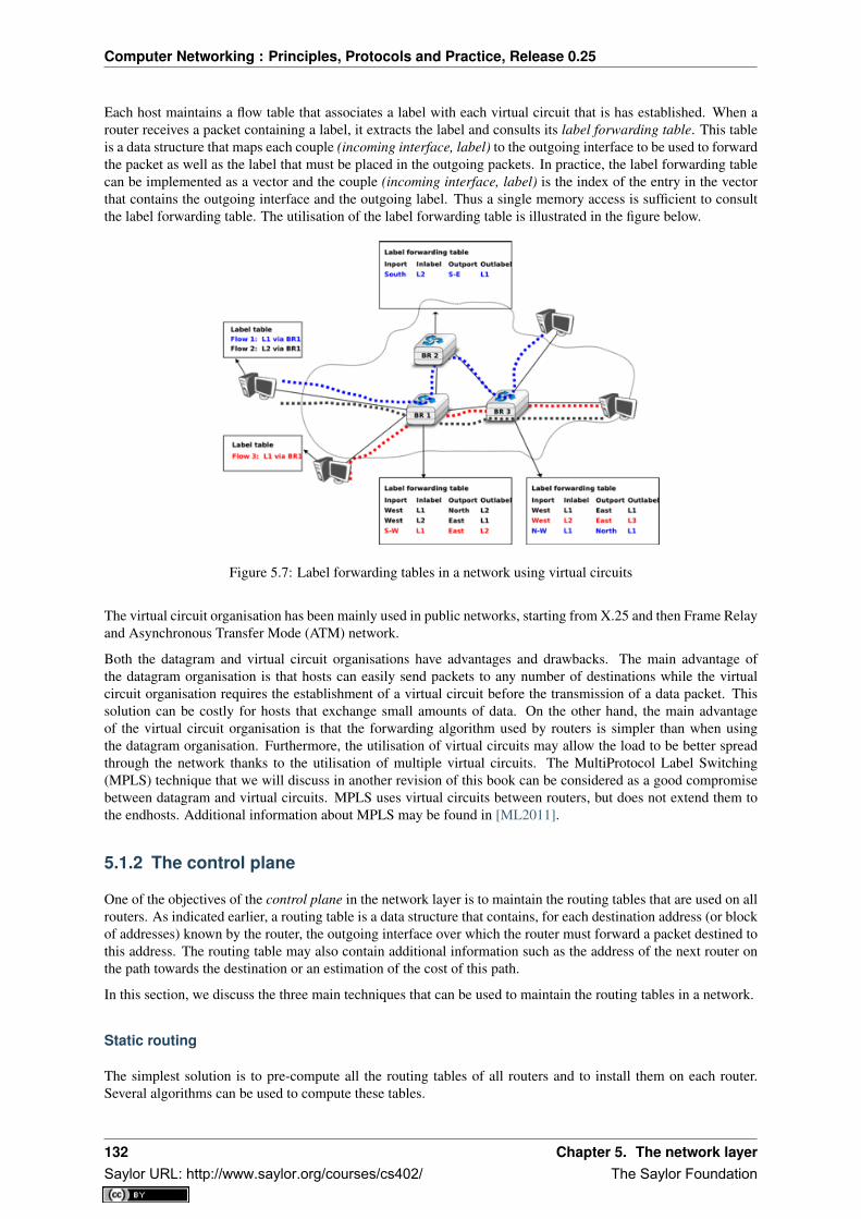
Computer Networking : Principles, Protocols and Practice, Release 0.25
Each host maintains a flow table that associates a label with each virtual circuit that is has established. When arouter receives a packet containing a label, it extracts the label and consults its label forwarding table. This tableis a data structure that maps each couple (incoming interface, label) to the outgoing interface to be used to forwardthe packet as well as the label that must be placed in the outgoing packets. In practice, the label forwarding tablecan be implemented as a vector and the couple (incoming interface, label) is the index of the entry in the vectorthat contains the outgoing interface and the outgoing label. Thus a single memory access is sufficient to consultthe label forwarding table. The utilisation of the label forwarding table is illustrated in the figure below.
Figure 5.7: Label forwarding tables in a network using virtual circuits
The virtual circuit organisation has been mainly used in public networks, starting from X.25 and then Frame Relayand Asynchronous Transfer Mode (ATM) network.
Both the datagram and virtual circuit organisations have advantages and drawbacks. The main advantage ofthe datagram organisation is that hosts can easily send packets to any number of destinations while the virtualcircuit organisation requires the establishment of a virtual circuit before the transmission of a data packet. Thissolution can be costly for hosts that exchange small amounts of data. On the other hand, the main advantageof the virtual circuit organisation is that the forwarding algorithm used by routers is simpler than when usingthe datagram organisation. Furthermore, the utilisation of virtual circuits may allow the load to be better spreadthrough the network thanks to the utilisation of multiple virtual circuits. The MultiProtocol Label Switching(MPLS) technique that we will discuss in another revision of this book can be considered as a good compromisebetween datagram and virtual circuits. MPLS uses virtual circuits between routers, but does not extend them tothe endhosts. Additional information about MPLS may be found in [ML2011].
5.1.2 The control plane
One of the objectives of the control plane in the network layer is to maintain the routing tables that are used on allrouters. As indicated earlier, a routing table is a data structure that contains, for each destination address (or blockof addresses) known by the router, the outgoing interface over which the router must forward a packet destined tothis address. The routing table may also contain additional information such as the address of the next router onthe path towards the destination or an estimation of the cost of this path.
In this section, we discuss the three main techniques that can be used to maintain the routing tables in a network.
Static routing
The simplest solution is to pre-compute all the routing tables of all routers and to install them on each router.Several algorithms can be used to compute these tables.
132 Chapter 5. The network layerSaylor URL: http://www.saylor.org/courses/cs402/ The Saylor Foundation

Computer Networking : Principles, Protocols and Practice, Release 0.25
A simple solution is to use shortest path routing and to minimise the number of intermediate routers to reacheach destination. More complex algorithms can take into account the expected load on the links to ensure thatcongestion does not occur for a given traffic demand. These algorithms must all ensure that :
• all routers are configured with a route to reach each destination
• none of the paths composed with the entries found in the routing tables contain a cycle. Such a cycle wouldlead to a forwarding loop.
The figure below shows sample routing tables in a five routers network.
Figure 5.8: Routing tables in a simple network
The main drawback of static routing is that it does not adapt to the evolution of the network. When a new routeror link is added, all routing tables must be recomputed. Furthermore, when a link or router fails, the routing tablesmust be updated as well.
Distance vector routing
Distance vector routing is a simple distributed routing protocol. Distance vector routing allows routers to auto-matically discover the destinations reachable inside the network as well as the shortest path to reach each of thesedestinations. The shortest path is computed based on metrics or costs that are associated to each link. We usel.cost to represent the metric that has been configured for link l on a router.
Each router maintains a routing table. The routing table R can be modelled as a data structure that stores, for eachknown destination address d, the following attributes :
• R[d].link is the outgoing link that the router uses to forward packets towards destination d
• R[d].cost is the sum of the metrics of the links that compose the shortest path to reach destination d
• R[d].time is the timestamp of the last distance vector containing destination d
A router that uses distance vector routing regularly sends its distance vector over all its interfaces. The distancevector is a summary of the router’s routing table that indicates the distance towards each known destination. Thisdistance vector can be computed from the routing table by using the pseudo-code below.
Every N seconds:v=Vector()for d in R[]:
# add destination d to vectorv.add(Pair(d,R[d].cost))
for i in interfaces# send vector v on this interfacesend(v,interface)
When a router boots, it does not know any destination in the network and its routing table only contains itself. Itthus sends to all its neighbours a distance vector that contains only its address at a distance of 0. When a routerreceives a distance vector on link l, it processes it as follows.
# V : received Vector# l : link over which vector is receiveddef received(V,l):
# received vector from link lfor d in V[]
5.1. Principles 133Saylor URL: http://www.saylor.org/courses/cs402/ The Saylor Foundation

Computer Networking : Principles, Protocols and Practice, Release 0.25
if not (d in R[]) :# new routeR[d].cost=V[d].cost+l.costR[d].link=lR[d].time=now
else :# existing route, is the new better ?if ( ((V[d].cost+l.cost) < R[d].cost) or ( R[d].link == l) ) :
# Better route or change to current routeR[d].cost=V[d].cost+l.costR[d].link=lR[d].time=now
The router iterates over all addresses included in the distance vector. If the distance vector contains an addressthat the router does not know, it inserts the destination inside its routing table via link l and at a distance which isthe sum between the distance indicated in the distance vector and the cost associated to link l. If the destinationwas already known by the router, it only updates the corresponding entry in its routing table if either :
• the cost of the new route is smaller than the cost of the already known route ( (V[d].cost+l.cost) < R[d].cost)
• the new route was learned over the same link as the current best route towards this destination ( R[d].link== l)
The first condition ensures that the router discovers the shortest path towards each destination. The second condi-tion is used to take into account the changes of routes that may occur after a link failure or a change of the metricassociated to a link.
To understand the operation of a distance vector protocol, let us consider the network of five routers shown below.
Figure 5.9: Operation of distance vector routing in a simple network
Assume that A is the first to send its distance vector [A=0].
• B and D process the received distance vector and update their routing table with a route towards A.
• D sends its distance vector [D=0,A=1] to A and E. E can now reach A and D.
• C sends its distance vector [C=0] to B and E
• E sends its distance vector [E=0,D=1,A=2,C=2] to D, B and C. B can now reach A, C, D and E
• B sends its distance vector [B=0,A=1,C=1,D=2,E=1] to A, C and E. A, B, C and E can now reach alldestinations.
• A sends its distance vector [A=0,B=1,C=2,D=1,E=2] to B and D.
At this point, all routers can reach all other routers in the network thanks to the routing tables shown in the figurebelow.
To deal with link and router failures, routers use the timestamp stored in their routing table. As all routers sendtheir distance vector every N seconds, the timestamp of each route should be regularly refreshed. Thus no routeshould have a timestamp older than N seconds, unless the route is not reachable anymore. In practice, to copewith the possible loss of a distance vector due to transmission errors, routers check the timestamp of the routesstored in their routing table every N seconds and remove the routes that are older than 3 × N seconds. When arouter notices that a route towards a destination has expired, it must first associate an∞ cost to this route and send
134 Chapter 5. The network layerSaylor URL: http://www.saylor.org/courses/cs402/ The Saylor Foundation

Computer Networking : Principles, Protocols and Practice, Release 0.25
Figure 5.10: Routing tables computed by distance vector in a simple network
its distance vector to its neighbours to inform them. The route can then be removed from the routing table aftersome time (e.g. 3×N seconds), to ensure that the neighbouring routers have received the bad news, even if somedistance vectors do not reach them due to transmission errors.
Consider the example above and assume that the link between routers A and B fails. Before the failure, A used Bto reach destinations B, C and E while B only used the A-B link to reach A. The affected entries timeout on routersA and B and they both send their distance vector.
• A sends its distance vector [A = 0, D = ∞, C = ∞, D = 1, E = ∞]. D knows that it cannot reach Banymore via A
• D sends its distance vector [D = 0, B = ∞, A = 1, C = 2, E = 1] to A and E. A recovers routes towardsC and E via D.
• B sends its distance vector [B = 0, A = ∞, C = 1, D = 2, E = 1] to E and C. D learns that there is noroute anymore to reach A via B.
• E sends its distance vector [E = 0, A = 2, C = 1, D = 1, B = 1] to D, B and C. D learns a route towardsB. C and B learn a route towards A.
At this point, all routers have a routing table allowing them to reach all another routers, except router A, whichcannot yet reach router B. A recovers the route towards B once router D sends its updated distance vector [A =1, B = 2, C = 2, D = 1, E = 1]. This last step is illustrated in figure Routing tables computed by distance vectorafter a failure, which shows the routing tables on all routers.
Figure 5.11: Routing tables computed by distance vector after a failure
Consider now that the link between D and E fails. The network is now partitioned into two disjoint parts : (A , D)and (B, E, C). The routes towards B, C and E expire first on router D. At this time, router D updates its routingtable.
If D sends [D = 0, A = 1, B = ∞, C = ∞, E = ∞], A learns that B, C and E are unreachable and updates itsrouting table.
Unfortunately, if the distance vector sent to A is lost or if A sends its own distance vector ( [A = 0, D = 1, B =3, C = 3, E = 2] ) at the same time as D sends its distance vector, D updates its routing table to use the
5.1. Principles 135Saylor URL: http://www.saylor.org/courses/cs402/ The Saylor Foundation

Computer Networking : Principles, Protocols and Practice, Release 0.25
shorter routes advertised by A towards B, C and E. After some time D sends a new distance vector : [D =0, A = 1, E = 3, C = 4, B = 4]. A updates its routing table and after some time sends its own distance vector[A = 0, D = 1, B = 5, C = 5, E = 4], etc. This problem is known as the count to infinity problem in networkingliterature. Routers A and D exchange distance vectors with increasing costs until these costs reach ∞. Thisproblem may occur in other scenarios than the one depicted in the above figure. In fact, distance vector routingmay suffer from count to infinity problems as soon as there is a cycle in the network. Cycles are necessary tohave enough redundancy to deal with link and router failures. To mitigate the impact of counting to infinity, somedistance vector protocols consider that 16 =∞. Unfortunately, this limits the metrics that network operators canuse and the diameter of the networks using distance vectors.
This count to infinity problem occurs because router A advertises to router D a route that it has learned via routerD. A possible solution to avoid this problem could be to change how a router creates its distance vector. Insteadof computing one distance vector and sending it to all its neighbors, a router could create a distance vector that isspecific to each neighbour and only contains the routes that have not been learned via this neighbour. This couldbe implemented by the following pseudocode.
Every N seconds:# one vector for each interfacefor l in interfaces:
v=Vector()for d in R[]:
if (R[d].link != i) :v=v+Pair(d,R[d.cost])
send(v)# end for d in R[]
#end for l in interfaces
This technique is called split-horizon. With this technique, the count to infinity problem would not have happenedin the above scenario, as router A would have advertised [A = 0], since it learned all its other routes via routerD. Another variant called split-horizon with poison reverse is also possible. Routers using this variant advertise acost of∞ for the destinations that they reach via the router to which they send the distance vector. This can beimplemented by using the pseudo-code below.
Every N seconds:for l in interfaces:
# one vector for each interfacev=Vector()for d in R[]:
if (R[d].link != i) :v=v+Pair(d,R[d.cost])
else:v=v+Pair(d,infinity);
send(v)# end for d in R[]
#end for l in interfaces
Unfortunately, split-horizon, is not sufficient to avoid all count to infinity problems with distance vector routing.Consider the failure of link A-B in the network of four routers below.
Figure 5.12: Count to infinity problem
136 Chapter 5. The network layerSaylor URL: http://www.saylor.org/courses/cs402/ The Saylor Foundation
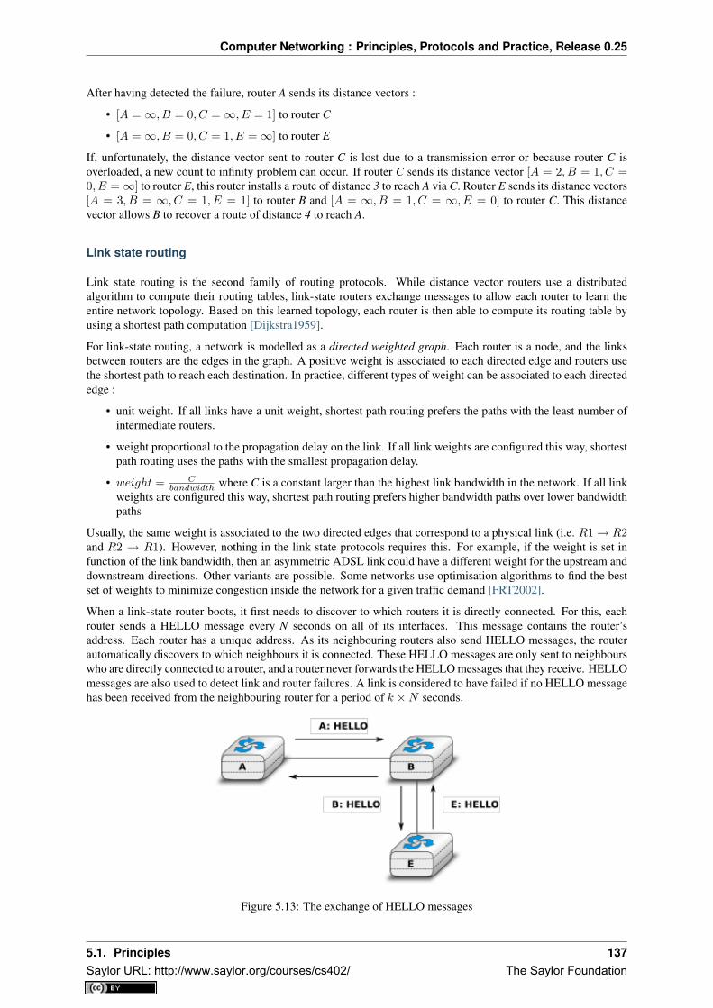
Computer Networking : Principles, Protocols and Practice, Release 0.25
After having detected the failure, router A sends its distance vectors :
• [A =∞, B = 0, C =∞, E = 1] to router C
• [A =∞, B = 0, C = 1, E =∞] to router E
If, unfortunately, the distance vector sent to router C is lost due to a transmission error or because router C isoverloaded, a new count to infinity problem can occur. If router C sends its distance vector [A = 2, B = 1, C =0, E =∞] to router E, this router installs a route of distance 3 to reach A via C. Router E sends its distance vectors[A = 3, B = ∞, C = 1, E = 1] to router B and [A = ∞, B = 1, C = ∞, E = 0] to router C. This distancevector allows B to recover a route of distance 4 to reach A.
Link state routing
Link state routing is the second family of routing protocols. While distance vector routers use a distributedalgorithm to compute their routing tables, link-state routers exchange messages to allow each router to learn theentire network topology. Based on this learned topology, each router is then able to compute its routing table byusing a shortest path computation [Dijkstra1959].
For link-state routing, a network is modelled as a directed weighted graph. Each router is a node, and the linksbetween routers are the edges in the graph. A positive weight is associated to each directed edge and routers usethe shortest path to reach each destination. In practice, different types of weight can be associated to each directededge :
• unit weight. If all links have a unit weight, shortest path routing prefers the paths with the least number ofintermediate routers.
• weight proportional to the propagation delay on the link. If all link weights are configured this way, shortestpath routing uses the paths with the smallest propagation delay.
• weight = Cbandwidth where C is a constant larger than the highest link bandwidth in the network. If all link
weights are configured this way, shortest path routing prefers higher bandwidth paths over lower bandwidthpaths
Usually, the same weight is associated to the two directed edges that correspond to a physical link (i.e. R1→ R2and R2 → R1). However, nothing in the link state protocols requires this. For example, if the weight is set infunction of the link bandwidth, then an asymmetric ADSL link could have a different weight for the upstream anddownstream directions. Other variants are possible. Some networks use optimisation algorithms to find the bestset of weights to minimize congestion inside the network for a given traffic demand [FRT2002].
When a link-state router boots, it first needs to discover to which routers it is directly connected. For this, eachrouter sends a HELLO message every N seconds on all of its interfaces. This message contains the router’saddress. Each router has a unique address. As its neighbouring routers also send HELLO messages, the routerautomatically discovers to which neighbours it is connected. These HELLO messages are only sent to neighbourswho are directly connected to a router, and a router never forwards the HELLO messages that they receive. HELLOmessages are also used to detect link and router failures. A link is considered to have failed if no HELLO messagehas been received from the neighbouring router for a period of k ×N seconds.
Figure 5.13: The exchange of HELLO messages
5.1. Principles 137Saylor URL: http://www.saylor.org/courses/cs402/ The Saylor Foundation

Computer Networking : Principles, Protocols and Practice, Release 0.25
Once a router has discovered its neighbours, it must reliably distribute its local links to all routers in the networkto allow them to compute their local view of the network topology. For this, each router builds a link-state packet(LSP) containing the following information :
• LSP.Router : identification (address) of the sender of the LSP
• LSP.age : age or remaining lifetime of the LSP
• LSP.seq : sequence number of the LSP
• LSP.Links[] : links advertised in the LSP. Each directed link is represented with the following information: - LSP.Links[i].Id : identification of the neighbour - LSP.Links[i].cost : cost of the link
These LSPs must be reliably distributed inside the network without using the router’s routing table since thesetables can only be computed once the LSPs have been received. The Flooding algorithm is used to efficientlydistribute the LSPs of all routers. Each router that implements flooding maintains a link state database (LSDB)containing the most recent LSP sent by each router. When a router receives an LSP, it first verifies whether thisLSP is already stored inside its LSDB. If so, the router has already distributed the LSP earlier and it does not needto forward it. Otherwise, the router forwards the LSP on all links except the link over which the LSP was received.Reliable flooding can be implemented by using the following pseudo-code.
# links is the set of all links on the router# Router R’s LSP arrival on link lif newer(LSP, LSDB(LSP.Router)) :
LSDB.add(LSP)for i in links :
if i!=l :send(LSP,i)
else:# LSP has already been flooded
In this pseudo-code, LSDB(r) returns the most recent LSP originating from router r that is stored in the LSDB.newer(lsp1,lsp2) returns true if lsp1 is more recent than lsp2. See the note below for a discussion on how newercan be implemented.
Note: Which is the most recent LSP ?
A router that implements flooding must be able to detect whether a received LSP is newer than the stored LSP.This requires a comparison between the sequence number of the received LSP and the sequence number of theLSP stored in the link state database. The ARPANET routing protocol [MRR1979] used a 6 bits sequence numberand implemented the comparison as follows RFC 789
def newer( lsp1, lsp2 ):return ( ( ( lsp1.seq > lsp2.seq) and ( (lsp1.seq-lsp2.seq)<=32) ) or
( ( lsp1.seq < lsp2.seq) and ( (lsp2.seq-lsp1.seq)> 32) ) )
This comparison takes into account the modulo 26 arithmetic used to increment the sequence numbers. Intuitively,the comparison divides the circle of all sequence numbers into two halves. Usually, the sequence number of thereceived LSP is equal to the sequence number of the stored LSP incremented by one, but sometimes the sequencenumbers of two successive LSPs may differ, e.g. if one router has been disconnected from the network for sometime. The comparison above worked well until October 27, 1980. On this day, the ARPANET crashed completely.The crash was complex and involved several routers. At one point, LSP 40 and LSP 44 from one of the routerswere stored in the LSDB of some routers in the ARPANET. As LSP 44 was the newest, it should have replacedby LSP 40 on all routers. Unfortunately, one of the ARPANET routers suffered from a memory problem andsequence number 40 (101000 in binary) was replaced by 8 (001000 in binary) in the buggy router and flooded.Three LSPs were present in the network and 44 was newer than 40 which is newer than 8, but unfortunately 8 wasconsidered to be newer than 44... All routers started to exchange these three link state packets for ever and theonly solution to recover from this problem was to shutdown the entire network RFC 789.
Current link state routing protocols usually use 32 bits sequence numbers and include a special mechanism in theunlikely case that a sequence number reaches the maximum value (using a 32 bits sequence number space takes136 years if a link state packet is generated every second).
138 Chapter 5. The network layerSaylor URL: http://www.saylor.org/courses/cs402/ The Saylor Foundation

Computer Networking : Principles, Protocols and Practice, Release 0.25
To deal with the memory corruption problem, link state packets contain a checksum. This checksum is computedby the router that generates the LSP. Each router must verify the checksum when it receives or floods an LSP.Furthermore, each router must periodically verify the checksums of the LSPs stored in its LSDB.
Flooding is illustrated in the figure below. By exchanging HELLO messages, each router learns its direct neigh-bours. For example, router E learns that it is directly connected to routers D, B and C. Its first LSP has sequencenumber 0 and contains the directed links E->D, E->B and E->C. Router E sends its LSP on all its links and routersD, B and C insert the LSP in their LSDB and forward it over their other links.
Figure 5.14: Flooding : example
Flooding allows LSPs to be distributed to all routers inside the network without relying on routing tables. In theexample above, the LSP sent by router E is likely to be sent twice on some links in the network. For example,routers B and C receive E‘s LSP at almost the same time and forward it over the B-C link. To avoid sending thesame LSP twice on each link, a possible solution is to slightly change the pseudo-code above so that a router waitsfor some random time before forwarding a LSP on each link. The drawback of this solution is that the delay toflood an LSP to all routers in the network increases. In practice, routers immediately flood the LSPs that containnew information (e.g. addition or removal of a link) and delay the flooding of refresh LSPs (i.e. LSPs that containexactly the same information as the previous LSP originating from this router) [FFEB2005].
To ensure that all routers receive all LSPs, even when there are transmissions errors, link state routing protocolsuse reliable flooding. With reliable flooding, routers use acknowledgements and if necessary retransmissionsto ensure that all link state packets are successfully transferred to all neighbouring routers. Thanks to reliableflooding, all routers store in their LSDB the most recent LSP sent by each router in the network. By combiningthe received LSPs with its own LSP, each router can compute the entire network topology.
Figure 5.15: Link state databases received by all routers
5.1. Principles 139Saylor URL: http://www.saylor.org/courses/cs402/ The Saylor Foundation

Computer Networking : Principles, Protocols and Practice, Release 0.25
Note: Static or dynamic link metrics ?
As link state packets are flooded regularly, routers are able to measure the quality (e.g. delay or load) of theirlinks and adjust the metric of each link according to its current quality. Such dynamic adjustments were includedin the ARPANET routing protocol [MRR1979] . However, experience showed that it was difficult to tune thedynamic adjustments and ensure that no forwarding loops occur in the network [KZ1989]. Today’s link staterouting protocols use metrics that are manually configured on the routers and are only changed by the networkoperators or network management tools [FRT2002].
When a link fails, the two routers attached to the link detect the failure by the lack of HELLO messages receivedin the last k ×N seconds. Once a router has detected a local link failure, it generates and floods a new LSP thatno longer contains the failed link and the new LSP replaces the previous LSP in the network. As the two routersattached to a link do not detect this failure exactly at the same time, some links may be announced in only onedirection. This is illustrated in the figure below. Router E has detected the failures of link E-B and flooded a newLSP, but router B has not yet detected the failure.
Figure 5.16: The two-way connectivity check
When a link is reported in the LSP of only one of the attached routers, routers consider the link as having failed andthey remove it from the directed graph that they compute from their LSDB. This is called the two-way connectivitycheck. This check allows link failures to be flooded quickly as a single LSP is sufficient to announce such badnews. However, when a link comes up, it can only be used once the two attached routers have sent their LSPs. Thetwo-way connectivity check also allows for dealing with router failures. When a router fails, all its links fail bydefinition. Unfortunately, it does not, of course, send a new LSP to announce its failure. The two-way connectivitycheck ensures that the failed router is removed from the graph.
When a router has failed, its LSP must be removed from the LSDB of all routers 1. This can be done by using theage field that is included in each LSP. The age field is used to bound the maximum lifetime of a link state packetin the network. When a router generates a LSP, it sets its lifetime (usually measured in seconds) in the age field.All routers regularly decrement the age of the LSPs in their LSDB and a LSP is discarded once its age reaches 0.Thanks to the age field, the LSP from a failed router does not remain in the LSDBs forever.
To compute its routing table, each router computes the spanning tree rooted at itself by using Dijkstra’s shortestpath algorithm [Dijkstra1959]. The routing table can be derived automatically from the spanning as shown in thefigure below.
5.2 Internet Protocol
The Internet Protocol (IP) is the network layer protocol of the TCP/IP protocol suite. IP allows the applicationsrunning above the transport layer (UDP/TCP) to use a wide range of heterogeneous datalink layers. IP was
1 It should be noted that link state routing assumes that all routers in the network have enough memory to store the entire LSDB. Therouters that do not have enough memory to store the entire LSDB cannot participate in link state routing. Some link state routing protocolsallow routers to report that they do not have enough memory and must be removed from the graph by the other routers in the network.
140 Chapter 5. The network layerSaylor URL: http://www.saylor.org/courses/cs402/ The Saylor Foundation

Computer Networking : Principles, Protocols and Practice, Release 0.25
Figure 5.17: Computation of the routing table
designed when most point-to-point links were telephone lines with modems. Since then, IP has been able to useLocal Area Networks (Ethernet, Token Ring, FDDI, ...), new wide area data link layer technologies (X.25, ATM,Frame Relay, ...) and more recently wireless networks (802.11, 802.15, UMTS, GPRS, ...). The flexibility of IPand its ability to use various types of underlying data link layer technologies is one of its key advantages.
Figure 5.18: IP and the reference model
The current version of IP is version 4 specified in RFC 791. We first describe this version and later explain IPversion 6, which is expected to replace IP version 4 in the not so distant future.
5.2.1 IP version 4
IP version 4 is the data plane protocol of the network layer in the TCP/IP protocol suite. The design of IP version4 was based on the following assumptions :
• IP should provide an unreliable connectionless service (TCP provides reliability when required by the ap-plication)
• IP operates with the datagram transmission mode
• IP addresses have a fixed size of 32 bits
• IP must be usable above different types of datalink layers
• IP hosts exchange variable length packets
The addresses are an important part of any network layer protocol. In the late 1970s, the developers of IPv4designed IPv4 for a research network that would interconnect some research labs and universities. For this utilisa-tion, 32 bits wide addresses were much larger than the expected number of hosts on the network. Furthermore, 32bits was a nice address size for software-based routers. None of the developers of IPv4 were expecting that IPv4would become as widely used as it is today.
IPv4 addresses are encoded as a 32 bits field. IPv4 addresses are often represented in dotted-decimal format as asequence of four integers separated by a dot. The first integer is the decimal representation of the most significantbyte of the 32 bits IPv4 address, ... For example,
• 1.2.3.4 corresponds to 00000001000000100000001100000100
5.2. Internet Protocol 141Saylor URL: http://www.saylor.org/courses/cs402/ The Saylor Foundation

Computer Networking : Principles, Protocols and Practice, Release 0.25
• 127.0.0.1 corresponds to 01111111000000000000000000000001
• 255.255.255.255 corresponds to 11111111111111111111111111111111
An IPv4 address is used to identify an interface on a router or a host. A router has thus as many IPv4 addresses asthe number of interfaces that it has in the datalink layer. Most hosts have a single datalink layer interface and thushave a single IPv4 address. However, with the growth of wireless, more and more hosts have several datalink layerinterfaces (e.g. an Ethernet interface and a WiFi interface). These hosts are said to be multihomed. A multihomedhost with two interfaces has thus two IPv4 addresses.
An important point to be defined in a network layer protocol is the allocation of the network layer addresses. Anaive allocation scheme would be to provide an IPv4 address to each host when the host is attached to the Interneton a first come first served basis. With this solution, a host in Belgium could have address 2.3.4.5 while anotherhost located in Africa would use address 2.3.4.6. Unfortunately, this would force all routers to maintain a specificroute towards each host. The figure below shows a simple enterprise network with two routers and three hosts andthe associated routing tables if such isolated addresses were used.
Figure 5.19: Scalability issues when using isolated IP addresses
To preserve the scalability of the routing system, it is important to minimize the number of routes that are stored oneach router. A router cannot store and maintain one route for each of the almost 1 billion hosts that are connectedto today’s Internet. Routers should only maintain routes towards blocks of addresses and not towards individualhosts. For this, hosts are grouped in subnets based on their location in the network. A typical subnet groupsall the hosts that are part of the same enterprise. An enterprise network is usually composed of several LANsinterconnected by routers. A small block of addresses from the Enterprise’s block is usually assigned to eachLAN. An IPv4 address is composed of two parts : a subnetwork identifier and a host identifier. The subnetworkidentifier is composed of the high order bits of the address and the host identifier is encoded in the low order bitsof the address. This is illustrated in the figure below.
Figure 5.20: The subnetwork and host identifiers inside an IPv4 address
When a router needs to forward a packet, it must know the subnet of the destination address to be able to consultits forwarding table to forward the packet. RFC 791 proposed to use the high-order bits of the address to encodethe length of the subnet identifier. This led to the definition of three classes of unicast addresses 2
2 In addition to the A, B and C classes, RFC 791 also defined the D and E classes of IPv4 addresses. Class D (resp. E) addresses are thosewhose high order bits are set to 1110 (resp. 1111). Class D addresses are used by IP multicast and will be explained later. Class E addressesare currently unused, but there are some discussions on possible future usages [WMH2008] [FLM2008]
142 Chapter 5. The network layerSaylor URL: http://www.saylor.org/courses/cs402/ The Saylor Foundation

Computer Networking : Principles, Protocols and Practice, Release 0.25
Class High-order bits Length of subnet id Number of networks Addresses per networkClass A 0 8 bits 128 16,777,216 (224)Class B 10 16 bits 16,384 65,536 (216)Class C 110 24 bits 2,097,152 256 (28)
However, these three classes of addresses were not flexible enough. A class A subnet was too large for mostorganisations and a class C subnet was too small. Flexibility was added by the introduction of variable-lengthsubnets in RFC 1519. With variable-length subnets, the subnet identifier can be any size, from 1 to 31 bits.Variable-length subnets allow the network operators to use a subnet that better matches the number of hosts thatare placed inside the subnet. A subnet identifier or IPv4 prefix is usually 3 represented as A.B.C.D/p where A.B.C.Dis the network address obtained by concatenating the subnet identifier with a host identifier containing only 0 andp is the length of the subnet identifier in bits. The table below provides examples of IP subnets.
Subnet Number of addresses Smallest address Highest address10.0.0.0/8 16,777,216 10.0.0.0 10.255.255.255192.168.0.0/16 65,536 192.168.0.0 192.168.255.255198.18.0.0/15 131,072 198.18.0.0 198.19.255.255192.0.2.0/24 256 192.0.2.0 192.0.2.25510.0.0.0/30 4 10.0.0.0 10.0.0.310.0.0.0/31 2 10.0.0.0 10.0.0.1
The figure below provides a simple example of the utilisation of IPv4 subnets in an enterprise network. The lengthof the subnet identifier assigned to a LAN usually depends on the expected number of hosts attached to the LAN.For point-to-point links, many deployments have used /30 prefixes, but recent routers are now using /31 subnetson point-to-point links RFC 3021 or do not even use IPv4 addresses on such links 4.
Figure 5.21: IP subnets in a simple enterprise network
A second issue concerning the addresses of the network layer is the allocation scheme that is used to allocateblocks of addresses to organisations. The first allocation scheme was based on the different classes of addresses.The pool of IPv4 addresses was managed by a secretariat who allocated address blocks on a first-come first servedbasis. Large organisations such as IBM, BBN, as well as Stanford or the MIT were able to obtain a class A addressblock. Most organisations requested a class B address block containing 65536 addresses, which was suitable formost enterprises and universities. The table below provides examples of some IPv4 address blocks in the class Bspace.
3 Another way of representing IP subnets is to use netmasks. A netmask is a 32 bits field whose p high order bits are set to 1 and the loworder bits are set to 0. The number of high order bits set 1 indicates the length of the subnet identifier. Netmasks are usually represented inthe same dotted decimal format as IPv4 addresses. For example 10.0.0.0/8 would be represented as 10.0.0.0 255.0.0.0 while 192.168.1.0/24would be represented as 192.168.1.0 255.255.255.0. In some cases, the netmask can be represented in hexadecimal.
4 A point-to-point link to which no IPv4 address has been allocated is called an unnumbered link. See RFC 1812 section 2.2.7 for adiscussion of such unnumbered links.
5.2. Internet Protocol 143Saylor URL: http://www.saylor.org/courses/cs402/ The Saylor Foundation

Computer Networking : Principles, Protocols and Practice, Release 0.25
Subnet Organisation130.100.0.0/16 Ericsson, Sweden130.101.0.0/16 University of Akron, USA130.102.0.0/16 The University of Queensland, Australia130.103.0.0/16 Lotus Development, USA130.104.0.0/16 Universite catholique de Louvain, Belgium130.105.0.0/16 Open Software Foundation, USA
However, the Internet was a victim of its own success and in the late 1980s, many organisations were requestingblocks of IPv4 addresses and started connecting to the Internet. Most of these organisations requested class Baddress blocks, as class A address blocks were too large and in limited supply while class C address blocks wereconsidered to be too small. Unfortunately, there were only 16,384 different class B address blocks and this addressspace was being consumed quickly. As a consequence, the routing tables maintained by the routers were growingquickly and some routers had difficulties maintaining all these routes in their limited memory 5.
Figure 5.22: Evolution of the size of the routing tables on the Internet (Jul 1988- Dec 1992 - source : RFC 1518)
Faced with these two problems, the Internet Engineering Task Force decided to develop the Classless InterdomainRouting (CIDR) architecture RFC 1518. This architecture aims at allowing IP routing to scale better than theclass-based architecture. CIDR contains three important modifications compared to RFC 791.
1. IP address classes are deprecated. All IP equipment must use and support variable-length subnets.
2. IP address blocks are no longer allocated on a first-come-first-served basis. Instead, CIDR introduces ahierarchical address allocation scheme.
3. IP routers must use longest-prefix match when they lookup a destination address in their forwarding table
The last two modifications were introduced to improve the scalability of the IP routing system. The main draw-back of the first-come-first-served address block allocation scheme was that neighbouring address blocks wereallocated to very different organisations and conversely, very different address blocks were allocated to similar or-ganisations. With CIDR, address blocks are allocated by Regional IP Registries (RIR) in an aggregatable manner.A RIR is responsible for a large block of addresses and a region. For example, RIPE is the RIR that is responsiblefor Europe. A RIR allocates smaller address blocks from its large block to Internet Service Providers RFC 2050.Internet Service Providers then allocate smaller address blocks to their customers. When an organisation requestsan address block, it must prove that it already has or expects to have in the near future, a number of hosts orcustomers that is equivalent to the size of the requested address block.
The main advantage of this hierarchical address block allocation scheme is that it allows the routers to maintainfewer routes. For example, consider the address blocks that were allocated to some of the Belgian universities asshown in the table below.
5 Example routers from this period include the Cisco AGS http://www.knossos.net.nz/don/wn1.html and AGS+http://www.ciscopress.com/articles/article.asp?p=25296
144 Chapter 5. The network layerSaylor URL: http://www.saylor.org/courses/cs402/ The Saylor Foundation

Computer Networking : Principles, Protocols and Practice, Release 0.25
Address block Organisation130.104.0.0/16 Universite catholique de Louvain134.58.0.0/16 Katholiek Universiteit Leuven138.48.0.0/16 Facultes universitaires Notre-Dame de la Paix139.165.0.0/16 Universite de Liege164.15.0.0/16 Universite Libre de Bruxelles
These universities are all connected to the Internet exclusively via Belnet. As each university has been allocateda different address block, the routers of Belnet must announce one route for each university and all routers onthe Internet must maintain a route towards each university. In contrast, consider all the high schools and thegovernment institutions that are connected to the Internet via Belnet. An address block was assigned to theseinstitutions after the introduction of CIDR in the 193.190.0.0/15 address block owned by Belnet. With CIDR,Belnet can announce a single route towards 193.190.0.0/15 that covers all of these high schools.
However, there is one difficulty with the aggregatable variable length subnets used by CIDR. Consider for exampleFEDICT, a government institution that uses the 193.191.244.0/23 address block. Assume that in addition to beingconnected to the Internet via Belnet , FEDICT also wants to be connected to another Internet Service Provider.The FEDICT network is then said to be multihomed. This is shown in the figure below.
Figure 5.23: Multihoming and CIDR
With such a multihomed network, routers R1 and R2 would have two routes towards IPv4 address 193.191.245.88: one route via Belnet (193.190.0.0/15) and one direct route (193.191.244.0/23). Both routes match IPv4 address193.192.145.88. Since RFC 1519 when a router knows several routes towards the same destination address, itmust forward packets along the route having the longest prefix length. In the case of 193.191.245.88, this is theroute 193.191.244.0/23 that is used to forward the packet. This forwarding rule is called the longest prefix matchor the more specific match. All IPv4 routers implement this forwarding rule.
To understand the longest prefix match forwarding, consider the figure below. With this rule, the route 0.0.0.0/0plays a particular role. As this route has a prefix length of 0 bits, it matches all destination addresses. This routeis often called the default route.
• a packet with destination 192.168.1.1 received by router R is destined to the router itself. It is delivered tothe appropriate transport protocol.
• a packet with destination 11.2.3.4 matches two routes : 11.0.0.0/8 and 0.0.0.0/0. The packet is forwardedon the West interface.
• a packet with destination 130.4.3.4 matches one route : 0.0.0.0/0. The packet is forwarded on the Northinterface.
• a packet with destination 4.4.5.6 matches two routes : 4.0.0.0/8 and 0.0.0.0/0. The packet is forwarded onthe West interface.
5.2. Internet Protocol 145Saylor URL: http://www.saylor.org/courses/cs402/ The Saylor Foundation

Computer Networking : Principles, Protocols and Practice, Release 0.25
• a packet with destination 4.10.11.254 matches three routes : 4.0.0.0/8, 4.10.11.0/24 and ‘0.0.0.0/0. Thepacket is forwarded on the South interface.
Figure 5.24: Longest prefix match example
The longest prefix match can be implemented by using different data structures. One possibility is to use a trie.The figure below shows a trie that encodes six routes having different outgoing interfaces.
Figure 5.25: A trie representing a routing table
Note: Special IPv4 addresses
Most unicast IPv4 addresses can appear as source and destination addresses in packets on the global Internet.However, it is worth noting that some blocks of IPv4 addresses have a special usage, as described in RFC 5735.These include :
146 Chapter 5. The network layerSaylor URL: http://www.saylor.org/courses/cs402/ The Saylor Foundation

Computer Networking : Principles, Protocols and Practice, Release 0.25
• 0.0.0.0/8, which is reserved for self-identification. A common address in this block is 0.0.0.0, which issometimes used when a host boots and does not yet know its IPv4 address.
• 127.0.0.0/8, which is reserved for loopback addresses. Each host implementing IPv4 must have a loopbackinterface (that is not attached to a datalink layer). By convention, IPv4 address 127.0.0.1 is assigned to thisinterface. This allows processes running on a host to use TCP/IP to contact other processes running on thesame host. This can be very useful for testing purposes.
• 10.0.0.0/8, 172.16.0.0/12 and 192.168.0.0/16 are reserved for private networks that are not directly attachedto the Internet. These addresses are often called private addresses or RFC 1918 addresses.
• 169.254.0.0/16 is used for link-local addresses RFC 3927. Some hosts use an address in this block whenthey are connected to a network that does not allocate addresses as expected.
IPv4 packets
Now that we have clarified the allocation of IPv4 addresses and the utilisation of the longest prefix match toforward IPv4 packets, we can have a more detailed look at IPv4 by starting with the format of the IPv4 packets.The IPv4 packet format was defined in RFC 791. Apart from a few clarifications and some backward compatiblechanges, the IPv4 packet format did not change significantly since the publication of RFC 791. All IPv4 packetsuse the 20 bytes header shown below. Some IPv4 packets contain an optional header extension that is describedlater.
Figure 5.26: The IP version 4 header
The main fields of the IPv4 header are :
• a 4 bits version that indicates the version of IP used to build the header. Using a version field in the headerallows the network layer protocol to evolve.
• a 4 bits IP Header Length (IHL) that indicates the length of the IP header in 32 bits words. This field allowsIPv4 to use options if required, but as it is encoded as a 4 bits field, the IPv4 header cannot be longer than64 bytes.
• an 8 bits DS field that is used for Quality of Service and whose usage is described later.
• an 8 bits Protocol field that indicates the transport layer protocol that must process the packet’s payload atthe destination. Common values for this field 6 are 6 for TCP and 17 for UDP
• a 16 bits length field that indicates the total length of the entire IPv4 packet (header and payload) in bytes.This implies that an IPv4 packet cannot be longer than 65535 bytes.
• a 32 bits source address field that contains the IPv4 address of the source host
• a 32 bits destination address field that contains the IPv4 address of the destination host
• a 16 bits checksum that protects only the IPv4 header against transmission errors
The other fields of the IPv4 header are used for specific purposes. The first is the 8 bits Time To Live (TTL) field.This field is used by IPv4 to avoid the risk of having an IPv4 packet caught in an infinite loop due to a transient
6 See http://www.iana.org/assignments/protocol-numbers/ for the list of all assigned Protocol numbers
5.2. Internet Protocol 147Saylor URL: http://www.saylor.org/courses/cs402/ The Saylor Foundation

Computer Networking : Principles, Protocols and Practice, Release 0.25
or permanent error in routing tables 7. Consider for example the situation depicted in the figure below wheredestination D uses address 11.0.0.56. If S sends a packet towards this destination, the packet is forwarded to routerB which forwards it to router C that forwards it back to router A, etc.
Figure 5.27: Forwarding loops in an IP network
Unfortunately, such loops can occur for two reasons in IP networks. First, if the network uses static routing, theloop can be caused by a simple configuration error. Second, if the network uses dynamic routing, such a loop canoccur transiently, for example during the convergence of the routing protocol after a link or router failure. TheTTL field of the IPv4 header ensures that even if there are forwarding loops in the network, packets will not loopforever. Hosts send their IPv4 packets with a positive TTL (usually 64 or more 8). When a router receives an IPv4packet, it first decrements the TTL by one. If the TTL becomes 0, the packet is discarded and a message is sentback to the packet’s source (see section ICMP). Otherwise, the router performs a lookup in its forwarding table toforward the packet.
A second problem for IPv4 is the heterogeneity of the datalink layer. IPv4 is used above many very differentdatalink layers. Each datalink layer has its own characteristics and as indicated earlier, each datalink layer ischaracterised by a maximum frame size. From IP’s point of view, a datalink layer interface is characterised by itsMaximum Transmission Unit (MTU). The MTU of an interface is the largest IPv4 packet (including header) thatit can send. The table below provides some common MTU sizes 9.
Datalink layer MTUEthernet 1500 bytesWiFi 2272 bytesATM (AAL5) 9180 bytes802.15.4 102 or 81 bytesToken Ring 4464 bytesFDDI 4352 bytes
Although IPv4 can send 64 KBytes long packets, few datalink layer technologies that are used today are able tosend a 64 KBytes IPv4 packet inside a frame. Furthermore, as illustrated in the figure below, another problemis that a host may send a packet that would be too large for one of the datalink layers used by the intermediaterouters.
Figure 5.28: The need for fragmentation and reassembly
7 The initial IP specification in RFC 791 suggested that routers would decrement the TTL at least once every second. This would ensurethat a packet would never remain for more than TTL seconds in the network. However, in practice most router implementations simply choseto decrement the TTL by one.
8 The initial TTL value used to send IP packets vary from one implementation to another. Most current IP implementations use an initialTTL of 64 or more. See http://members.cox.net/~ndav1/self_published/TTL_values.html for additional information.
9 Supporting IP over the 802.15.4 datalink layer technology requires special mechanisms. See RFC 4944 for a discussion of the specialproblems posed by 802.15.4
148 Chapter 5. The network layerSaylor URL: http://www.saylor.org/courses/cs402/ The Saylor Foundation

Computer Networking : Principles, Protocols and Practice, Release 0.25
To solve these problems, IPv4 includes a packet fragmentation and reassembly mechanism. Both hosts and inter-mediate routers may fragment an IPv4 packet if the packet is too long to be sent via the datalink layer. In IPv4,fragmentation is completely performed in the IP layer and a large IPv4 is fragmented into two or more IPv4 pack-ets (called fragments). The IPv4 fragments of a large packet are normal IPv4 packets that are forwarded towardsthe destination of the large packet by intermediate routers.
The IPv4 fragmentation mechanism relies on four fields of the IPv4 header : Length, Identification, the flags andthe Fragment Offset. The IPv4 header contains two flags : More fragments and Don’t Fragment (DF). When theDF flag is set, this indicates that the packet cannot be fragmented.
The basic operation of the IPv4 fragmentation is as follows. A large packet is fragmented into two or morefragments. The size of all fragments, except the last one, is equal to the Maximum Transmission Unit of the linkused to forward the packet. Each IPv4 packet contains a 16 bits Identification field. When a packet is fragmented,the Identification of the large packet is copied in all fragments to allow the destination to reassemble the receivedfragments together. In each fragment, the Fragment Offset indicates, in units of 8 bytes, the position of the payloadof the fragment in the payload of the original packet. The Length field in each fragment indicates the length ofthe payload of the fragment as in a normal IPv4 packet. Finally, the More fragments flag is set only in the lastfragment of a large packet.
The following pseudo-code details the IPv4 fragmentation, assuming that the packet does not contain options.
#mtu : maximum size of the packet (including header) of outgoing linkif p.len < mtu :
send(p)# packet is too largemaxpayload=8*int((mtu-20)/8) # must be n times 8 bytesif p.flags==’DF’ :
discard(p)# packet must be fragmentedpayload=p[IP].payloadpos=0while len(payload) > 0 :
if len(payload) > maxpayload :toSend=IP(dest=p.dest,src=p.src,
ttl=p.ttl, id=p.id,frag=p.frag+(pos/8),len=mtu, proto=p.proto)/payload[0:maxpayload]
pos=pos+maxpayloadpayload=payload[maxpayload+1:]
elsetoSend=IP(dest=p.dest,src=p.src,
ttl=p.ttl, id=p.id,frag=p.frag+(pos/8),flags=p.flags,len=len(payload), proto=p.proto)/payload
forward(toSend)
The fragments of an IPv4 packet may arrive at the destination in any order, as each fragment is forwarded inde-pendently in the network and may follow different paths. Furthermore, some fragments may be lost and neverreach the destination.
The reassembly algorithm used by the destination host is roughly as follows. First, the destination can verifywhether a received IPv4 packet is a fragment or not by checking the value of the More fragments flag and theFragment Offset. If the Fragment Offset is set to 0 and the More fragments flag is reset, the received packet has notbeen fragmented. Otherwise, the packet has been fragmented and must be reassembled. The reassembly algorithmrelies on the Identification field of the received fragments to associate a fragment with the corresponding packetbeing reassembled. Furthermore, the Fragment Offset field indicates the position of the fragment payload in theoriginal unfragmented packet. Finally, the packet with the More fragments flag reset allows the destination todetermine the total length of the original unfragmented packet.
Note that the reassembly algorithm must deal with the unreliability of the IP network. This implies that a fragmentmay be duplicated or a fragment may never reach the destination. The destination can easily detect fragmentduplication thanks to the Fragment Offset. To deal with fragment losses, the reassembly algorithm must bound the
5.2. Internet Protocol 149Saylor URL: http://www.saylor.org/courses/cs402/ The Saylor Foundation

Computer Networking : Principles, Protocols and Practice, Release 0.25
time during which the fragments of a packet are stored in its buffer while the packet is being reassembled. Thiscan be implemented by starting a timer when the first fragment of a packet is received. If the packet has not beenreassembled upon expiration of the timer, all fragments are discarded and the packet is considered to be lost.
The original IP specification, in RFC 791, defined several types of options that can be added to the IP header.Each option is encoded using a type length value format. They are not widely used today and are thus only brieflydescribed. Additional details may be found in RFC 791.
The most interesting options in IPv4 are the three options that are related to routing. The Record route option wasdefined to allow network managers to determine the path followed by a packet. When the Record route option waspresent, routers on the packet’s path had to insert their IP address in the option. This option was implemented,but as the optional part of the IPv4 header can only contain 44 bytes, it is impossible to discover an entire pathon the global Internet. traceroute(8), despite its limitations, is a better solution to record the path towards adestination.
The other routing options are the Strict source route and the Loose source route option. The main idea behindthese options is that a host may want, for any reason, to specify the path to be followed by the packets that it sends.The Strict source route option allows a host to indicate inside each packet the exact path to be followed. The Strictsource route option contains a list of IPv4 address and a pointer to indicate the next address in the list. When arouter receives a packet containing this option, it does not lookup the destination address in its routing table butforwards the packet directly to the next router in the list and advances the pointer. This is illustrated in the figurebelow where S forces its packets to follow the RA-RB-RD path.
Figure 5.29: Usage of the Strict source route option
The maximum length of the optional part of the IPv4 header is a severe limitation for the Strict source routeoption as for the Record Route option. The Loose source route option does not suffer from this limitation. Thisoption allows the sending host to indicate inside its packet some of the routers that must be traversed to reach thedestination. This is shown in the figure below. S sends a packet containing a list of addresses and a pointer to thenext router in the list. Initially, this pointer points to RB. When RA receives the packet sent by S, it looks up in itsforwarding table the address pointed in the Loose source route option and not the destination address. The packetis then forwarded to router RB that recognises its address in the option and advances the pointer. As there is noaddress listed in the Loose source route option anymore, RB and other downstream routers forward the packet byperforming a lookup for the destination address.
Figure 5.30: Usage of the Loose source route option
These two options are usually ignored by routers because they cause security problems RFC 6274.
150 Chapter 5. The network layerSaylor URL: http://www.saylor.org/courses/cs402/ The Saylor Foundation

Computer Networking : Principles, Protocols and Practice, Release 0.25
5.2.2 ICMP version 4
It is sometimes necessary for intermediate routers or the destination host to inform the sender of the packet of aproblem that occurred while processing a packet. In the TCP/IP protocol suite, this reporting is done by the InternetControl Message Protocol (ICMP). ICMP is defined in RFC 792. ICMP messages are carried as the payload ofIP packets (the protocol value reserved for ICMP is 1). An ICMP message is composed of an 8 byte header anda variable length payload that usually contains the first bytes of the packet that triggered the transmission of theICMP message.
Figure 5.31: ICMP version 4 ( RFC 792)
In the ICMP header, the Type and Code fields indicate the type of problem that was detected by the sender of theICMP message. The Checksum protects the entire ICMP message against transmission errors and the Data fieldcontains additional information for some ICMP messages.
The main types of ICMP messages are :
• Destination unreachable : a Destination unreachable ICMP message is sent when a packetcannot be delivered to its destination due to routing problems. Different types of unreachabilityare distinguished :
– Network unreachable : this ICMP message is sent by a router that does not have a route forthe subnet containing the destination address of the packet
– Host unreachable : this ICMP message is sent by a router that is attached to the subnetthat contains the destination address of the packet, but this destination address cannot bereached at this time
– Protocol unreachable : this ICMP message is sent by a destination host that has received apacket, but does not support the transport protocol indicated in the packet’s Protocol field
– Port unreachable : this ICMP message is sent by a destination host that has received apacket destined to a port number, but no server process is bound to this port
• Fragmentation needed : this ICMP message is sent by a router that receives a packet with theDon’t Fragment flag set that is larger than the MTU of the outgoing interface
• Redirect : this ICMP message can be sent when there are two routers on the same LAN. Considera LAN with one host and two routers : R1 and R2. Assume that R1 is also connected to subnet130.104.0.0/16 while R2 is connected to subnet 138.48.0.0/16. If a host on the LAN sends apacket towards 130.104.1.1 to R2, R2 needs to forward the packet again on the LAN to reachR1. This is not optimal as the packet is sent twice on the same LAN. In this case, R2 could sendan ICMP Redirect message to the host to inform it that it should have sent the packet directly toR1. This allows the host to send the other packets to 130.104.1.1 directly via R1.
• Parameter problem : this ICMP message is sent when a router or a host receives an IP packetcontaining an error (e.g. an invalid option)
5.2. Internet Protocol 151Saylor URL: http://www.saylor.org/courses/cs402/ The Saylor Foundation

Computer Networking : Principles, Protocols and Practice, Release 0.25
Figure 5.32: ICMP redirect
• Source quench : a router was supposed to send this message when it had to discard packets dueto congestion. However, sending ICMP messages in case of congestion was not the best wayto reduce congestion and since the inclusion of a congestion control scheme in TCP, this ICMPmessage has been deprecated.
• Time Exceeded : there are two types of Time Exceeded ICMP messages
– TTL exceeded : a TTL exceeded message is sent by a router when it discards an IPv4 packetbecause its TTL reached 0.
– Reassembly time exceeded : this ICMP message is sent when a destination has been unableto reassemble all the fragments of a packet before the expiration of its reassembly timer.
• Echo request and Echo reply : these ICMP messages are used by the ping(8) network debug-ging software.
Note: Redirection attacks
ICMP redirect messages are useful when several routers are attached to the same LAN as hosts. However, theyshould be used with care as they also create an important security risk. One of the most annoying attacks in anIP network is called the man in the middle attack. Such an attack occurs if an attacker is able to receive, process,possibly modify and forward all the packets exchanged between a source and a destination. As the attackerreceives all the packets it can easily collect passwords or credit card numbers or even inject fake information in anestablished TCP connection. ICMP redirects unfortunately enable an attacker to easily perform such an attack. Inthe figure above, consider host H that is attached to the same LAN as A and R1. If H sends to A an ICMP redirectfor prefix 138.48.0.0/16, A forwards to H all the packets that it wants to send to this prefix. H can then forwardthem to R2. To avoid these attacks, hosts should ignore the ICMP redirect messages that they receive.
ping(8) is often used by network operators to verify that a given IP address is reachable. Each host is supposed10 to reply with an ICMP Echo reply message when its receives an ICMP Echo request message. A sample usageof ping(8) is shown below.
ping 130.104.1.1PING 130.104.1.1 (130.104.1.1): 56 data bytes64 bytes from 130.104.1.1: icmp_seq=0 ttl=243 time=19.961 ms64 bytes from 130.104.1.1: icmp_seq=1 ttl=243 time=22.072 ms64 bytes from 130.104.1.1: icmp_seq=2 ttl=243 time=23.064 ms64 bytes from 130.104.1.1: icmp_seq=3 ttl=243 time=20.026 ms64 bytes from 130.104.1.1: icmp_seq=4 ttl=243 time=25.099 ms--- 130.104.1.1 ping statistics ---5 packets transmitted, 5 packets received, 0% packet lossround-trip min/avg/max/stddev = 19.961/22.044/25.099/1.938 ms
10 Until a few years ago, all hosts replied to Echo request ICMP messages. However, due to the security problems that have affected TCP/IPimplementations, many of these implementations can now be configured to disable answering Echo request ICMP messages.
152 Chapter 5. The network layerSaylor URL: http://www.saylor.org/courses/cs402/ The Saylor Foundation

Computer Networking : Principles, Protocols and Practice, Release 0.25
Another very useful debugging tool is traceroute(8). The traceroute man page describes this tool as “printthe route packets take to network host”. traceroute uses the TTL exceeded ICMP messages to discover the inter-mediate routers on the path towards a destination. The principle behind traceroute is very simple. When a routerreceives an IP packet whose TTL is set to 1 it decrements the TTL and is forced to return to the sending host aTTL exceeded ICMP message containing the header and the first bytes of the discarded IP packet. To discover allrouters on a network path, a simple solution is to first send a packet whose TTL is set to 1, then a packet whoseTTL is set to 2, etc. A sample traceroute output is shown below.
traceroute www.ietf.orgtraceroute to www.ietf.org (64.170.98.32), 64 hops max, 40 byte packets1 CsHalles3.sri.ucl.ac.be (192.168.251.230) 5.376 ms 1.217 ms 1.137 ms2 CtHalles.sri.ucl.ac.be (192.168.251.229) 1.444 ms 1.669 ms 1.301 ms3 CtPythagore.sri.ucl.ac.be (130.104.254.230) 1.950 ms 4.688 ms 1.319 ms4 fe.m20.access.lln.belnet.net (193.191.11.9) 1.578 ms 1.272 ms 1.259 ms5 10ge.cr2.brueve.belnet.net (193.191.16.22) 5.461 ms 4.241 ms 4.162 ms6 212.3.237.13 (212.3.237.13) 5.347 ms 4.544 ms 4.285 ms7 ae-11-11.car1.Brussels1.Level3.net (4.69.136.249) 5.195 ms 4.304 ms 4.329 ms8 ae-6-6.ebr1.London1.Level3.net (4.69.136.246) 8.892 ms 8.980 ms 8.830 ms9 ae-100-100.ebr2.London1.Level3.net (4.69.141.166) 8.925 ms 8.950 ms 9.006 ms10 ae-41-41.ebr1.NewYork1.Level3.net (4.69.137.66) 79.590 ms
ae-43-43.ebr1.NewYork1.Level3.net (4.69.137.74) 78.140 msae-42-42.ebr1.NewYork1.Level3.net (4.69.137.70) 77.663 ms
11 ae-2-2.ebr1.Newark1.Level3.net (4.69.132.98) 78.290 ms 83.765 ms 90.006 ms12 ae-14-51.car4.Newark1.Level3.net (4.68.99.8) 78.309 ms 78.257 ms 79.709 ms13 ex1-tg2-0.eqnwnj.sbcglobal.net (151.164.89.249) 78.460 ms 78.452 ms 78.292 ms14 151.164.95.190 (151.164.95.190) 157.198 ms 160.767 ms 159.898 ms15 ded-p10-0.pltn13.sbcglobal.net (151.164.191.243) 161.872 ms 156.996 ms 159.425 ms16 AMS-1152322.cust-rtr.swbell.net (75.61.192.10) 158.735 ms 158.485 ms 158.588 ms17 mail.ietf.org (64.170.98.32) 158.427 ms 158.502 ms 158.567 ms
The above traceroute(8) output shows a 17 hops path between a host at UCLouvain and one of the mainIETF servers. For each hop, traceroute provides the IPv4 address of the router that sent the ICMP message and themeasured round-trip-time between the source and this router. traceroute sends three probes with each TTL value.In some cases, such as at the 10th hop above, the ICMP messages may be received from different addresses. Thisis usually because different packets from the same source have followed different paths 11 in the network.
Another important utilisation of ICMP messages is to discover the maximum MTU that can be used to reach adestination without fragmentation. As explained earlier, when an IPv4 router receives a packet that is larger thanthe MTU of the outgoing link, it must fragment the packet. Unfortunately, fragmentation is a complex operationand routers cannot perform it at line rate [KM1995]. Furthermore, when a TCP segment is transported in an IPpacket that is fragmented in the network, the loss of a single fragment forces TCP to retransmit the entire segment(and thus all the fragments). If TCP was able to send only packets that do not require fragmentation in thenetwork, it could retransmit only the information that was lost in the network. In addition, IP reassembly causesseveral challenges at high speed as discussed in RFC 4963. Using IP fragmentation to allow UDP applications toexchange large messages raises several security issues [KPS2003].
ICMP, combined with the Don’t fragment (DF) IPv4 flag, is used by TCP implementations to discover the largestMTU size that is allowed to reach a destination host without causing network fragmentation. This is the Path MTUdiscovery mechanism defined in RFC 1191. A TCP implementation that includes Path MTU discovery (most do)requests the IPv4 layer to send all segments inside IPv4 packets having the DF flag set. This prohibits intermediaterouters from fragmenting these packets. If a router needs to forward an unfragmentable packet over a link with asmaller MTU, it returns a Fragmentation needed ICMP message to the source, indicating the MTU of its outgoinglink. This ICMP message contains in the MTU of the router’s outgoing link in its Data field. Upon reception ofthis ICMP message, the source TCP implementation adjusts its Maximum Segment Size (MSS) so that the packetscontaining the segments that it sends can be forwarded by this router without requiring fragmentation.
11 A detailed analysis of traceroute output is outside the scope of this document. Additional information may be found in [ACO+2006] and[DT2007]
5.2. Internet Protocol 153Saylor URL: http://www.saylor.org/courses/cs402/ The Saylor Foundation

Computer Networking : Principles, Protocols and Practice, Release 0.25
Interactions between IPv4 and the datalink layer
As mentioned in the first section of this chapter, there are three main types of datalink layers : point-to-point links,LANs supporting broadcast and multicast and NBMA networks. There are two important issues to be addressedwhen using IPv4 in these types of networks. The first issue is how an IPv4 device obtains its IPv4 address. Thesecond issue is how IPv4 packets are exchanged over the datalink layer service.
On a point-to-point link, the IPv4 addresses of the communicating devices can be configured manually or byusing a simple protocol. IPv4 addresses are often configured manually on point-to-point links between routers.When point-to-point links are used to attach hosts to the network, automatic configuration is often preferred inorder to avoid problems with incorrect IPv4 addresses. For example, the PPP, specified in RFC 1661, includesan IP network control protocol that can be used by the router in the figure below to send the IPv4 address that theattached host must configure for its interface. The transmission of IPv4 packets on a point-to-point link will bediscussed in chapter chap:lan.
Figure 5.33: IPv4 on point-to-point links
Using IPv4 in a LAN introduces an additional problem. On a LAN, each device is identified by its unique datalinklayer address. The datalink layer service can be used by any host attached to the LAN to send a frame to any otherhost attached to the same LAN. For this, the sending host must know the datalink layer address of the destinationhost. For example, the figure below shows four hosts attached to the same LAN configured with IPv4 addressesin the 10.0.1.0/24 subnet and datalink layer addresses represented as a single character 12. In this network, if host10.0.1.22/24 wants to send an IPv4 packet to the host having address 10.0.1.8, it must know that the datalink layeraddress of this host is C.
Figure 5.34: A simple LAN
In a simple network such as the one shown above, it could be possible to manually configure the mapping betweenthe IPv4 addresses of the hosts and the corresponding datalink layer addresses. However, in a larger LAN this isimpossible. To ease the utilisation of LANs, IPv4 hosts must be able to automatically obtain the datalink layeraddress corresponding to any IPv4 address on the same LAN. This is the objective of the Address ResolutionProtocol (ARP) defined in RFC 826. ARP is a datalink layer protocol that is used by IPv4. It relies on the abilityof the datalink layer service to easily deliver a broadcast frame to all devices attached to the same LAN.
12 In practice, most local area networks use addresses encoded as a 48 bits field [802]_ . Some recent local area network technologies use64 bits addresses.
154 Chapter 5. The network layerSaylor URL: http://www.saylor.org/courses/cs402/ The Saylor Foundation

Computer Networking : Principles, Protocols and Practice, Release 0.25
The easiest way to understand the operation of ARP is to consider the simple network shown above and assumethat host 10.0.1.22/24 needs to send an IPv4 packet to host 10.0.1.8. As this IP address belongs to the samesubnet, the packet must be sent directly to its destination via the datalink layer service. To use this service, thesending host must find the datalink layer address that is attached to host 10.0.1.8. Each IPv4 host maintains anARP cache containing the list of all mappings between IPv4 addresses and datalink layer addresses that it knows.When an IPv4 hosts boots, its ARP cache is empty. 10.0.1.22 thus first consults its ARP cache. As the cachedoes not contain the requested mapping, host 10.0.1.22 sends a broadcast ARP query frame on the LAN. Theframe contains the datalink layer address of the sending host (A) and the requested IPv4 address (10.0.1.8). Thisbroadcast frame is received by all devices on the LAN and only the host that owns the requested IPv4 addressreplies by returning a unicast ARP reply frame with the requested mapping. Upon reception of this reply, thesending host updates its ARP cache and sends the IPv4 packet by using the datalink layer service. To deal withdevices that move or whose addresses are reconfigured, most ARP implementations remove the cache entries thathave not been used for a few minutes. Some implementations re-validate ARP cache entries from time to time bysending ARP queries 13.
Note: Security issues with the Address Resolution Protocol
ARP is an old and widely used protocol that was unfortunately designed when security issues were not a concern.ARP is almost insecure by design. Hosts using ARP can be subject to several types of attack. First, a malicioushost could create a denial of service attack on a LAN by sending random replies to the received ARP queries.This would pollute the ARP cache of the other hosts on the same LAN. On a fixed network, such attacks can bedetected by the system administrator who can physically remove the malicious hosts from the LAN. On a wirelessnetwork, removing a malicious host is much more difficult.
A second type of attack are the man-in-the-middle attacks. This name is used for network attacks where theattacker is able to read and possibly modify all the messages sent by the attacked devices. Such an attack ispossible in a LAN. Assume, in the figure above, that host 10.0.1.9 is malicious and would like to receive andmodify all the packets sent by host 10.0.1.22 to host 10.0.1.8. This can be achieved easily if host 10.0.1.9 manages,by sending fake ARP replies, to convince host 10.0.1.22 (resp. 10.0.1.8) that its own datalink layer address mustbe used to reach 10.0.1.8 (resp. 10.0.1.22).
ARP is used by all devices that are connected to a LAN and implement IPv4. Both routers and endhosts implementARP. When a host needs to send an IPv4 packet to a destination outside of its local subnet, it must first send thepacket to one of the routers that reside on this subnet. Consider for example the network shown in the figurebelow. Each host is configured with an IPv4 address in the 10.0.1.0/24 subnet and uses 10.0.1.1 as its defaultrouter. To send a packet to address 1.2.3.4, host 10.0.1.8 will first need to know the datalink layer of the defaultrouter. It will thus send an ARP request for 10.0.1.1. Upon reception of the ARP reply, host 10.0.1.8 updates itsARP table and sends its packet in a frame to its default router. The router will then forward the packet towards itsfinal destination.
Figure 5.35: A simple LAN with a router
In the early days of the Internet, IP addresses were manually configured on both hosts and routers and almost neverchanged. However, this manual configuration can be complex 14 and often causes errors that are sometimes diffi-cult to debug. Recent TCP/IP implementations are able to detect some of these misconfigurations. For example,if two hosts are attached to the same subnet with the same IPv4 address they will be unable to communicate. Todetect this problem hosts send an ARP request for their configured address each time their addressed is changedRFC 5227. If they receive an answer to this ARP request, they trigger an alarm or inform the system administrator.
13 See chapter 28 of [Benvenuti2005] for a description of the implementation of ARP in the Linux kernel.14 For example, consider all the options that can be specified for the ifconfig utility<http://en.wikipedia.org/wiki/Ifconfig> on Unix hosts.
5.2. Internet Protocol 155Saylor URL: http://www.saylor.org/courses/cs402/ The Saylor Foundation
Computer Networking : Principles, Protocols and Practice, Release 0.25
To ease the attachment of hosts to subnets, most networks now support the Dynamic Host Configuration Protocol(DHCP) RFC 2131. DHCP allows a host to automatically retrieve its assigned IPv4 address. A DHCP serveris associated to each subnet 15. Each DHCP server manages a pool of IPv4 addresses assigned to the subnet.When a host is first attached to the subnet, it sends a DHCP request message in a UDP segment (the DHCP serverlistens on port 67). As the host knows neither its IPv4 address nor the IPv4 address of the DHCP server, thisUDP segment is sent inside an IPv4 packet whose source and destination addresses are respectively 0.0.0.0 and255.255.255.255. The DHCP request may contain various options such as the name of the host, its datalink layeraddress, etc. The server captures the DHCP request and selects an unassigned address in its address pool. It thensends the assigned IPv4 address in a DHCP reply message which contains the datalink layer address of the hostand additional information such as the subnet mask of the IPv4 address, the address of the default router or theaddress of the DNS resolver. This DHCP reply message is sent in an IPv4 packet whose source and destinationaddresses are respectively the IPv4 address of the DHCP server and the 255.255.255.255 broadcast address. TheDHCP reply also specifies the lifetime of the address allocation. This forces the host to renew its address allocationonce it expires. Thanks to the limited lease time, IP addresses are automatically returned to the pool of addresseshosts are powered off. This reduces the waste of IPv4 addresses.
In an NBMA network, the interactions between IPv4 and the datalink layer are more complex as the ARP protocolcannot be used as in a LAN. Such NBMA networks use special servers that store the mappings between IP ad-dresses and the corresponding datalink layer address. Asynchronous Transfer Mode (ATM) networks for examplecan use either the ATMARP protocol defined in RFC 2225 or the NextHop Resolution Protocol (NHRP) definedin RFC 2332. ATM networks are less frequently used today and we will not describe the detailed operation ofthese servers.
Operation of IPv4 devices
At this point of the description of IPv4, it is useful to have a detailed look at how an IPv4 implementation sends,receives and forwards IPv4 packets. The simplest case is when a host needs to send a segment in an IPv4 packet.The host performs two operations. First, it must decide on which interface the packet will be sent. Second it mustcreate the corresponding IP packet(s).
To simplify the discussion in this section, we ignore the utilisation of IPv4 options. This is not a severe limitationas today IPv4 packets rarely contain options. Details about the processing of the IPv4 options may be found in therelevant RFCs, such as RFC 791. Furthermore, we also assume that only point-to-point links are used. We deferthe explanation of the operation of IPv4 over Local Area Networks until the next chapter.
An IPv4 host having n datalink layer interfaces manages n+ 1 IPv4 addresses :
• the 127.0.0.1/32 IPv4 address assigned by convention to its loopback address
• one A.B.C.D/p IPv4 address assigned to each of its n datalink layer interfaces
Such a host maintains a routing table containing one entry for its loopback address and one entry for each subnetidentifier assigned to its interfaces. Furthermore, the host usually uses one of its interfaces as the default interfacewhen sending packets that are not addressed to a directly connected destination. This is represented by the defaultroute : 0.0.0.0/0 that is associated to one interface.
When a transport protocol running on the host requests the transmission of a segment, it usually provides the IPv4destination address to the IPv4 layer in addition to the segment 16. The IPv4 implementation first performs alongest prefix match with the destination address in its routing table. The lookup returns the identification of theinterface that must be used to send the packet. The host can then create the IPv4 packet containing the segment.The source IPv4 address of the packet is the IPv4 address of the host on the interface returned by the longest prefixmatch. The Protocol field of the packet is set to the identification of the local transport protocol which createdthe segment. The TTL field of the packet is set to the default TTL used by the host. The host must now choosethe packet’s Identification. This Identification is important if the packet becomes fragmented in the network, as itensures that the destination is able to reassemble the received fragments. Ideally, a sending host should never senda packet twice with the same Identification to the same destination host, in order to ensure that all fragments arecorrectly reassembled by the destination. Unfortunately, with a 16 bits Identification field and an expected MSL of
15 In practice, there is usually one DHCP server per group of subnets and the routers capture on each subnet the DHCP messages andforward them to the DHCP server.
16 A transport protocol implementation can also specify whether the packet must be sent with the DF set or set. A TCP implementationusing Path MTU Discovery would always request the transmission of IPv4 packets with the DF flag set.
156 Chapter 5. The network layerSaylor URL: http://www.saylor.org/courses/cs402/ The Saylor Foundation

Computer Networking : Principles, Protocols and Practice, Release 0.25
2 minutes, this implies that the maximum bandwidth to a given destination is limited to roughly 286 Mbps. Witha more realistic 1500 bytes MTU, that bandwidth drops to 6.4 Mbps RFC 4963 if fragmentation must be possible17. This is very low and is another reason why hosts are highly encouraged to avoid fragmentation. If; despite allof this, the MTU of the outgoing interface is smaller than the packet’s length, the packet is fragmented. Finally,the packet’s checksum is computed before transmission.
When a host receives an IPv4 packet destined to itself, there are several operations that it must perform. First,it must check the packet’s checksum. If the checksum is incorrect, the packet is discarded. Then, it must checkwhether the packet has been fragmented. If yes, the packet is passed to the reassembly algorithm described earlier.Otherwise, the packet must be passed to the upper layer. This is done by looking at the Protocol field (6 for TCP,17 for UDP). If the host does not implement the transport layer protocol corresponding to the received Protocolfield, it sends a Protocol unreachable ICMP message to the sending host. If the received packet contains an ICMPmessage (Protocol field set to 1), the processing is more complex. An Echo-request ICMP message triggers thetransmission of an ICMP Echo-reply message. The other types of ICMP messages indicate an error that wascaused by a previously transmitted packet. These ICMP messages are usually forwarded to the transport protocolthat sent the erroneous packet. This can be done by inspecting the contents of the ICMP message that includesthe header and the first 64 bits of the erroneous packet. If the IP packet did not contain options, which is the casefor most IPv4 packets, the transport protocol can find in the first 32 bits of the transport header the source anddestination ports to determine the affected transport flow. This is important for Path MTU discovery for example.
When a router receives an IPv4 packet, it must first check the packet’s checksum. If the checksum is invalid, it isdiscarded. Otherwise, the router must check whether the destination address is one of the IPv4 addresses assignedto the router. If so, the router must behave as a host and process the packet as described above. Although routersmainly forward IPv4 packets, they sometimes need to be accessed as hosts by network operators or networkmanagement software.
If the packet is not addressed to the router, it must be forwarded on an outgoing interface according to the router’srouting table. The router first decrements the packet’s TTL. If the TTL reaches 0, a TTL Exceeded ICMP message issent back to the source. As the packet header has been modified, the checksum must be recomputed. Fortunately,as IPv4 uses an arithmetic checksum, a router can incrementally update the packet’s checksum as described inRFC 1624. Then, the router performs a longest prefix match for the packet’s destination address in its forwardingtable. If no match is found, the router must return a Destination unreachable ICMP message to the source.Otherwise, the lookup returns the interface over which the packet must be forwarded. Before forwarding thepacket over this interface, the router must first compare the length of the packet with the MTU of the outgoinginterface. If the packet is smaller than the MTU, it is forwarded. Otherwise, a Fragmentation needed ICMPmessage is sent if the DF flag was sent or the packet is fragmented if the DF was not set.
Note: Longest prefix match in IP routers
Performing the longest prefix match at line rate on routers requires highly tuned data structures and algorithms.Consider for example an implementation of the longest match based on a Radix tree on a router with a 10 Gbpslink. On such a link, a router can receive 31,250,000 40 bytes IPv4 packets every second. To forward the packetsat line rate, the router must process one IPv4 packet every 32 nanoseconds. This cannot be achieved by a softwareimplementation. For a hardware implementation, the main difficulty lies in the number of memory accesses thatare necessary to perform the longest prefix match. 32 nanoseconds is very small compared to the memory accessesthat are required by a naive longest prefix match implement. Additional information about faster longest prefixmatch algorithms may be found in [Varghese2005].
5.2.3 IP version 6
In the late 1980s and early 1990s the growth of the Internet was causing several operational problems on routers.Many of these routers had a single CPU and up to 1 MByte of RAM to store their operating system, packet buffersand routing tables. Given the rate of allocation of IPv4 prefixes to companies and universities willing to join theInternet, the routing tables where growing very quickly and some feared that all IPv4 prefixes would quickly beallocated. In 1987, a study cited in RFC 1752, estimated that there would be 100,000 networks in the near future.In August 1990, estimates indicated that the class B space would be exhausted by March 1994. Two types of
17 It should be noted that only the packets that can be fragmented (i.e. whose DF flag is reset) must have different Identification fields. TheIdentification field is not used in the packets having the DF flag set.
5.2. Internet Protocol 157Saylor URL: http://www.saylor.org/courses/cs402/ The Saylor Foundation

Computer Networking : Principles, Protocols and Practice, Release 0.25
solution were developed to solve this problem. The first short term solution was the introduction of Classless InterDomain Routing (CIDR). A second short term solution was the Network Address Translation (NAT) mechanism,defined in RFC 1631. NAT allowed multiple hosts to share a single public IP address, it is explained in sectionMiddleboxes.
However, in parallel with these short-term solutions, which have allowed the IPv4 Internet to continue to be usableuntil now, the Internet Engineering Task Force started to work on developing a replacement for IPv4. This workstarted with an open call for proposals, outlined in RFC 1550. Several groups responded to this call with proposalsfor a next generation Internet Protocol (IPng) :
• TUBA proposed in RFC 1347 and RFC 1561
• PIP proposed in RFC 1621
• SIPP proposed in RFC 1710
The IETF decided to pursue the development of IPng based on the SIPP proposal. As IP version 5 was alreadyused by the experimental ST-2 protocol defined in RFC 1819, the successor of IP version 4 is IP version 6. Theinitial IP version 6 defined in RFC 1752 was designed based on the following assumptions :
• IPv6 addresses are encoded as a 128 bits field
• The IPv6 header has a simple format that can easily be parsed by hardware devices
• A host should be able to configure its IPv6 address automatically
• Security must be part of IPv6
Note: The IPng address size
When the work on IPng started, it was clear that 32 bits was too small to encode an IPng address and all proposalsused longer addresses. However, there were many discussions about the most suitable address length. A firstapproach, proposed by SIP in RFC 1710, was to use 64 bit addresses. A 64 bits address space was 4 billion timeslarger than the IPv4 address space and, furthermore, from an implementation perspective, 64 bit CPUs were beingconsidered and 64 bit addresses would naturally fit inside their registers. Another approach was to use an existingaddress format. This was the TUBA proposal ( RFC 1347) that reuses the ISO CLNP 20 bytes addresses. The20 bytes addresses provided room for growth, but using ISO CLNP was not favored by the IETF partially due topolitical reasons, despite the fact that mature CLNP implementations were already available. 128 bits appeared tobe a reasonable compromise at that time.
IPv6 addressing architecture
The experience of IPv4 revealed that the scalability of a network layer protocol heavily dependson its addressing architecture. The designers of IPv6 spent a lot of effort defining its address-ing architecture RFC 3513. All IPv6 addresses are 128 bits wide. This implies that there are340, 282, 366, 920, 938, 463, 463, 374, 607, 431, 768, 211, 456(3.4 × 1038) different IPv6 addresses. As the sur-face of the Earth is about 510,072,000 km2, this implies that there are about 6.67 × 10²³ IPv6 addresses persquare meter on Earth. Compared to IPv4, which offers only 8 addresses per square kilometer, this is a significantimprovement on paper.
IPv6 supports unicast, multicast and anycast addresses. As with IPv4, an IPv6 unicast address is used to identifyone datalink-layer interface on a host. If a host has several datalink layer interfaces (e.g. an Ethernet interface anda WiFi interface), then it needs several IPv6 addresses. In general, an IPv6 unicast address is structured as shownin the figure below.
An IPv6 unicast address is composed of three parts :
1. A global routing prefix that is assigned to the Internet Service Provider that owns this block of addresses
2. A subnet identifier that identifies a customer of the ISP
3. An interface identifier that identifies a particular interface on an endsystem
158 Chapter 5. The network layerSaylor URL: http://www.saylor.org/courses/cs402/ The Saylor Foundation

Computer Networking : Principles, Protocols and Practice, Release 0.25
Figure 5.36: Structure of IPv6 unicast addresses
In today’s deployments, interface identifiers are always 64 bits wide. This implies that while there are 2128
different IPv6 addresses, they must be grouped in 264 subnets. This could appear as a waste of resources, howeverusing 64 bits for the host identifier allows IPv6 addresses to be auto-configured and also provides some benefitsfrom a security point of view, as explained in section ICMPv6
Note: Textual representation of IPv6 addresses
It is sometimes necessary to write IPv6 addresses in text format, e.g. when manually configuring addresses or fordocumentation purposes. The preferred format for writing IPv6 addresses is x:x:x:x:x:x:x:x, where the x ‘s arehexadecimal digits representing the eight 16-bit parts of the address. Here are a few examples of IPv6 addresses :
• ABCD:EF01:2345:6789:ABCD:EF01:2345:6789
• 2001:DB8:0:0:8:800:200C:417A
• FE80:0:0:0:219:E3FF:FED7:1204
IPv6 addresses often contain a long sequence of bits set to 0. In this case, a compact notation has been defined.With this notation, :: is used to indicate one or more groups of 16 bits blocks containing only bits set to 0. Forexample,
• 2001:DB8:0:0:8:800:200C:417A is represented as 2001:DB8::8:800:200C:417A
• FF01:0:0:0:0:0:0:101 is represented as FF01::101
• 0:0:0:0:0:0:0:1 is represented as ::1
• 0:0:0:0:0:0:0:0 is represented as ::
An IPv6 prefix can be represented as address/length, where length is the length of the prefix in bits. For example,the three notations below correspond to the same IPv6 prefix :
• 2001:0DB8:0000:CD30:0000:0000:0000:0000/60
• 2001:0DB8::CD30:0:0:0:0/60
• 2001:0DB8:0:CD30::/60
In practice, there are several types of IPv6 unicast address. Most of the IPv6 unicast addresses are allocated inblocks under the responsibility of IANA. The current IPv6 allocations are part of the 2000::/3 address block.Regional Internet Registries (RIR) such as RIPE in Europe, ARIN in North-America or AfriNIC in Africa haveeach received a block of IPv6 addresses that they sub-allocate to Internet Service Providers in their region. TheISPs then sub-allocate addresses to their customers.
When considering the allocation of IPv6 addresses, two types of address allocations are often distinguished. TheRIRs allocate provider-independent (PI) addresses. PI addresses are usually allocated to Internet Service Providersand large companies that are connected to at least two different ISPs [CSP2009]. Once a PI address block hasbeen allocated to a company, this company can use its address block with the provider of its choice and changeits provider at will. Internet Service Providers allocate provider-aggregatable (PA) address blocks from their ownPI address block to their customers. A company that is connected to only one ISP should only use PA addresses.
5.2. Internet Protocol 159Saylor URL: http://www.saylor.org/courses/cs402/ The Saylor Foundation
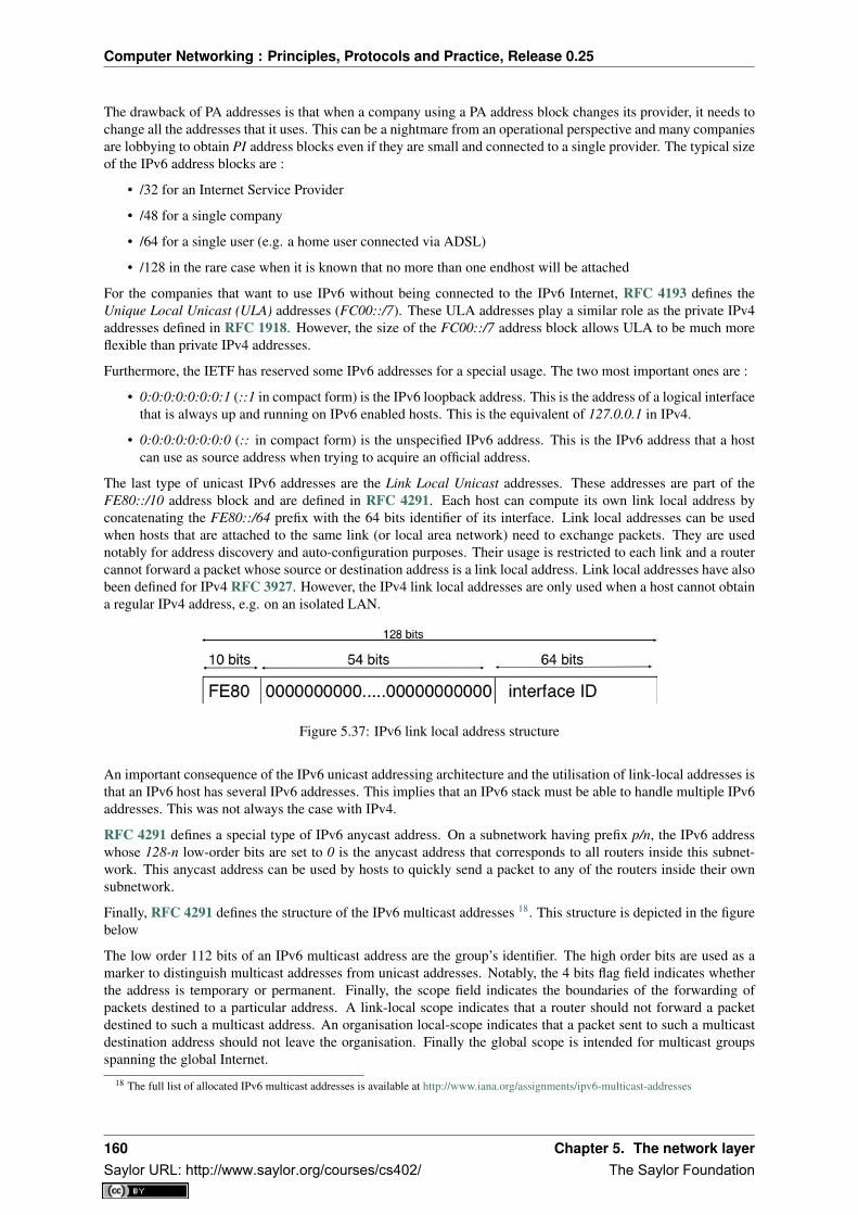
Computer Networking : Principles, Protocols and Practice, Release 0.25
The drawback of PA addresses is that when a company using a PA address block changes its provider, it needs tochange all the addresses that it uses. This can be a nightmare from an operational perspective and many companiesare lobbying to obtain PI address blocks even if they are small and connected to a single provider. The typical sizeof the IPv6 address blocks are :
• /32 for an Internet Service Provider
• /48 for a single company
• /64 for a single user (e.g. a home user connected via ADSL)
• /128 in the rare case when it is known that no more than one endhost will be attached
For the companies that want to use IPv6 without being connected to the IPv6 Internet, RFC 4193 defines theUnique Local Unicast (ULA) addresses (FC00::/7). These ULA addresses play a similar role as the private IPv4addresses defined in RFC 1918. However, the size of the FC00::/7 address block allows ULA to be much moreflexible than private IPv4 addresses.
Furthermore, the IETF has reserved some IPv6 addresses for a special usage. The two most important ones are :
• 0:0:0:0:0:0:0:1 (::1 in compact form) is the IPv6 loopback address. This is the address of a logical interfacethat is always up and running on IPv6 enabled hosts. This is the equivalent of 127.0.0.1 in IPv4.
• 0:0:0:0:0:0:0:0 (:: in compact form) is the unspecified IPv6 address. This is the IPv6 address that a hostcan use as source address when trying to acquire an official address.
The last type of unicast IPv6 addresses are the Link Local Unicast addresses. These addresses are part of theFE80::/10 address block and are defined in RFC 4291. Each host can compute its own link local address byconcatenating the FE80::/64 prefix with the 64 bits identifier of its interface. Link local addresses can be usedwhen hosts that are attached to the same link (or local area network) need to exchange packets. They are usednotably for address discovery and auto-configuration purposes. Their usage is restricted to each link and a routercannot forward a packet whose source or destination address is a link local address. Link local addresses have alsobeen defined for IPv4 RFC 3927. However, the IPv4 link local addresses are only used when a host cannot obtaina regular IPv4 address, e.g. on an isolated LAN.
Figure 5.37: IPv6 link local address structure
An important consequence of the IPv6 unicast addressing architecture and the utilisation of link-local addresses isthat an IPv6 host has several IPv6 addresses. This implies that an IPv6 stack must be able to handle multiple IPv6addresses. This was not always the case with IPv4.
RFC 4291 defines a special type of IPv6 anycast address. On a subnetwork having prefix p/n, the IPv6 addresswhose 128-n low-order bits are set to 0 is the anycast address that corresponds to all routers inside this subnet-work. This anycast address can be used by hosts to quickly send a packet to any of the routers inside their ownsubnetwork.
Finally, RFC 4291 defines the structure of the IPv6 multicast addresses 18. This structure is depicted in the figurebelow
The low order 112 bits of an IPv6 multicast address are the group’s identifier. The high order bits are used as amarker to distinguish multicast addresses from unicast addresses. Notably, the 4 bits flag field indicates whetherthe address is temporary or permanent. Finally, the scope field indicates the boundaries of the forwarding ofpackets destined to a particular address. A link-local scope indicates that a router should not forward a packetdestined to such a multicast address. An organisation local-scope indicates that a packet sent to such a multicastdestination address should not leave the organisation. Finally the global scope is intended for multicast groupsspanning the global Internet.
18 The full list of allocated IPv6 multicast addresses is available at http://www.iana.org/assignments/ipv6-multicast-addresses
160 Chapter 5. The network layerSaylor URL: http://www.saylor.org/courses/cs402/ The Saylor Foundation

Computer Networking : Principles, Protocols and Practice, Release 0.25
Figure 5.38: IPv6 multicast address structure
Among these addresses, some are well known. For example, all endsystem automatically belong to the FF02::1multicast group while all routers automatically belong to the FF02::2 multicast group. We discuss IPv6 multicastlater.
IPv6 packet format
The IPv6 packet format was heavily inspired by the packet format proposed for the SIPP protocol in RFC 1710.The standard IPv6 header defined in RFC 2460 occupies 40 bytes and contains 8 different fields, as shown in thefigure below.
Figure 5.39: The IP version 6 header ( RFC 2460)
Apart from the source and destination addresses, the IPv6 header contains the following fields :
• version : a 4 bits field set to 6 and intended to allow IP to evolve in the future if needed
• Traffic class : this 8 bits field plays a similar role as the DS byte in the IPv4 header
• Flow label : this field was initially intended to be used to tag packets belonging to the same flow. However,as of this writing, there is no clear guideline on how this field should be used by hosts and routers
• Payload length : this is the size of the packet payload in bytes. As the length is encoded as a 16 bits field,an IPv6 packet can contain up to 65535 bytes of payload.
• Next Header : this 8 bits field indicates the type 19 of header that follows the IPv6 header. It can be atransport layer header (e.g. 6 for TCP or 17 for UDP) or an IPv6 option. Handling options as a next headerallows simplifying the processing of IPv6 packets compared to IPv4.
19 The IANA maintains the list of all allocated Next Header types at http://www.iana.org/assignments/protocol-numbers/ The same registryis used for the IPv4 protocol field and for the IPv6 Next Header.
5.2. Internet Protocol 161Saylor URL: http://www.saylor.org/courses/cs402/ The Saylor Foundation

Computer Networking : Principles, Protocols and Practice, Release 0.25
• Hop Limit : this 8 bits field indicates the number of routers that can forward the packet. It is decrementedby one by each router and has the same purpose as the TTL field of the IPv4 header.
In comparison with IPv4, the IPv6 packets are much simpler and easier to process by routers. A first importantdifference is that there is no checksum inside the IPv6 header. This is mainly because all datalink layers andtransport protocols include a checksum or a CRC to protect their frames/segments against transmission errors.Adding a checksum in the IPv6 header would have forced each router to recompute the checksum of all packets,with limited benefit in detecting errors. In practice, an IP checksum allows for catching errors that occur insiderouters (e.g. due to memory corruption) before the packet reaches its destination. However, this benefit was foundto be too small given the reliability of current memories and the cost of computing the checksum on each router.
A second difference with IPv4 is that the IPv6 header does not support fragmentation and reassembly. Experiencewith IPv4 has shown that fragmenting packets in routers was costly [KM1995] and the developers of IPv6 havedecided that routers would not fragment packets anymore. If a router receives a packet that is too long to beforwarded, the packet is dropped and the router returns an ICMPv6 messages to inform the sender of the problem.The sender can then either fragment the packet or perform Path MTU discovery. In IPv6, packet fragmentation isperformed only by the source by using IPv6 options.
The third difference are the IPv6 options, which are simpler and easier to process than the IPv4 options.
Note: Header compression on low bandwidth links
Given the size of the IPv6 header, it can cause huge overhead on low bandwidth links, especially when smallpackets are exchanged such as for Voice over IP applications. In such environments, several techniques can beused to reduce the overhead. A first solution is to use data compression in the datalink layer to compress all theinformation exchanged [Thomborson1992]. These techniques are similar to the data compression algorithms usedin tools such as compress(1) or gzip(1)RFC 1951. They compress streams of bits without taking advantageof the fact that these streams contain IP packets with a known structure. A second solution is to compress the IPand TCP header. These header compression techniques, such as the one defined in RFC 2507 take advantage ofthe redundancy found in successive packets from the same flow to significantly reduce the size of the protocolheaders. Another solution is to define a compressed encoding of the IPv6 header that matches the capabilities ofthe underlying datalink layer RFC 4944.
IPv6 options
In IPv6, each option is considered as one header containing a multiple of 8 bytes to ensure that IPv6 options in apacket are aligned on 64 bit boundaries. IPv6 defines several type of options :
• the hop-by-hop options are options that must be processed by the routers on the packet’s path
• the type 0 routing header, which is similar to the IPv4 loose source routing option
• the fragmentation option, which is used when fragmenting an IPv6 packet
• the destination options
• the security options that allow IPv6 hosts to exchange packets with cryptographic authentication (AHheader) or encryption and authentication (ESP header)
RFC 2460 provides lots of detail on the encodings of the different types of options. In this section, we only discussome of them. The reader may consult RFC 2460 for more information about the other options. The first point tonote is that each option contains a Next Header field, which indicates the type of header that follows the option.A second point to note is that in order to allow routers to efficiently parse IPv6 packets, the options that must beprocessed by routers (hop-by-hop options and type 0 routing header) must appear first in the packet. This allowsthe router to process a packet without being forced to analyse all the packet’s options. A third point to note isthat hop-by-hop and destination options are encoded using a type length value format. Furthermore, the type fieldcontains bits that indicate whether a router that does not understand this option should ignore the option or discardthe packet. This allows the introduction of new options into the network without forcing all devices to be upgradedto support them at the same time.
Two hop-by-hop options have been defined. RFC 2675 specifies the jumbogram that enables IPv6 to supportpackets containing a payload larger than 65535 bytes. These jumbo packets have their payload length set to 0 and
162 Chapter 5. The network layerSaylor URL: http://www.saylor.org/courses/cs402/ The Saylor Foundation
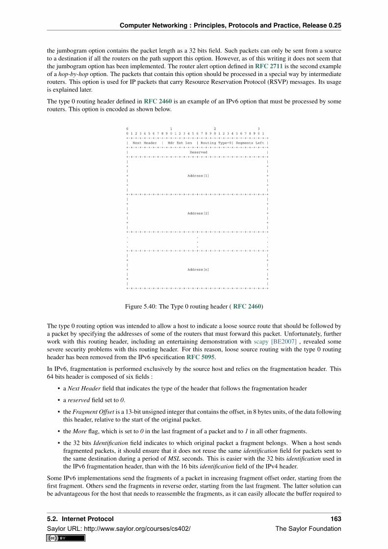
Computer Networking : Principles, Protocols and Practice, Release 0.25
the jumbogram option contains the packet length as a 32 bits field. Such packets can only be sent from a sourceto a destination if all the routers on the path support this option. However, as of this writing it does not seem thatthe jumbogram option has been implemented. The router alert option defined in RFC 2711 is the second exampleof a hop-by-hop option. The packets that contain this option should be processed in a special way by intermediaterouters. This option is used for IP packets that carry Resource Reservation Protocol (RSVP) messages. Its usageis explained later.
The type 0 routing header defined in RFC 2460 is an example of an IPv6 option that must be processed by somerouters. This option is encoded as shown below.
Figure 5.40: The Type 0 routing header ( RFC 2460)
The type 0 routing option was intended to allow a host to indicate a loose source route that should be followed bya packet by specifying the addresses of some of the routers that must forward this packet. Unfortunately, furtherwork with this routing header, including an entertaining demonstration with scapy [BE2007] , revealed somesevere security problems with this routing header. For this reason, loose source routing with the type 0 routingheader has been removed from the IPv6 specification RFC 5095.
In IPv6, fragmentation is performed exclusively by the source host and relies on the fragmentation header. This64 bits header is composed of six fields :
• a Next Header field that indicates the type of the header that follows the fragmentation header
• a reserved field set to 0.
• the Fragment Offset is a 13-bit unsigned integer that contains the offset, in 8 bytes units, of the data followingthis header, relative to the start of the original packet.
• the More flag, which is set to 0 in the last fragment of a packet and to 1 in all other fragments.
• the 32 bits Identification field indicates to which original packet a fragment belongs. When a host sendsfragmented packets, it should ensure that it does not reuse the same identification field for packets sent tothe same destination during a period of MSL seconds. This is easier with the 32 bits identification used inthe IPv6 fragmentation header, than with the 16 bits identification field of the IPv4 header.
Some IPv6 implementations send the fragments of a packet in increasing fragment offset order, starting from thefirst fragment. Others send the fragments in reverse order, starting from the last fragment. The latter solution canbe advantageous for the host that needs to reassemble the fragments, as it can easily allocate the buffer required to
5.2. Internet Protocol 163Saylor URL: http://www.saylor.org/courses/cs402/ The Saylor Foundation

Computer Networking : Principles, Protocols and Practice, Release 0.25
reassemble all fragments of the packet upon reception of the last fragment. When a host receives the first fragmentof an IPv6 packet, it cannot know a priori the length of the entire IPv6 packet.
The figure below provides an example of a fragmented IPv6 packet containing a UDP segment. The Next Headertype reserved for the IPv6 fragmentation option is 44.
Figure 5.41: IPv6 fragmentation example
Finally, the last type of IPv6 options is the Encaspulating Security Payload (ESP) defined in RFC 4303 and theAuthentication Header (AH) defined in RFC 4302. These two headers are used by IPSec RFC 4301. They arediscussed in another chapter.
5.2.4 ICMP version 6
ICMPv6 defined in RFC 4443 is the companion protocol for IPv6 as ICMPv4 is the companion protocol for IPv4.ICMPv6 is used by routers and hosts to report problems when processing IPv6 packets. However, as we will see inchapter The datalink layer and the Local Area Networks, ICMPv6 is also used when auto-configuring addresses.
The traditional utilisation of ICMPv6 is similar to ICMPv4. ICMPv6 messages are carried inside IPv6 packets(the Next Header field for ICMPv6 is 58). Each ICMP message contains an 8 bits header with a type field, a codefield and a 16 bits checksum computed over the entire ICMPv6 message. The message body contains a copy ofthe IPv6 packet in error.
Figure 5.42: ICMP version 6 packet format
ICMPv6 specifies two classes of messages : error messages that indicate a problem in handling a packet andinformational messages. Four types of error messages are defined in RFC 4443 :
• 1 [Destination Unreachable. Such an ICMPv6 message is sent when the destination address of a packetis unreachable. The code field of the ICMP header contains additional information about the type ofunreachability. The following codes are specified in RFC 4443]
– 0 : No route to destination. This indicates that the router that sent the ICMPv6 message did nothave a route towards the packet’s destination
164 Chapter 5. The network layerSaylor URL: http://www.saylor.org/courses/cs402/ The Saylor Foundation

Computer Networking : Principles, Protocols and Practice, Release 0.25
– 1 : Communication with destination administratively prohibited. This indicates that a firewall hasrefused to forward the packet towards its destination.
– 2 : Beyond scope of source address. This message can be sent if the source is using link-localaddresses to reach a global unicast address outside its subnet.
– 3 : Address unreachable. This message indicates that the packet reached the subnet of the desti-nation, but the host that owns this destination address cannot be reached.
– 4 : Port unreachable. This message indicates that the IPv6 packet was received by the destination,but there was no application listening to the specified port.
• 2 : Packet Too Big. The router that was to send the ICMPv6 message received an IPv6 packet that is largerthan the MTU of the outgoing link. The ICMPv6 message contains the MTU of this link in bytes. Thisallows the sending host to implement Path MTU discovery RFC 1981
• 3 : Time Exceeded. This error message can be sent either by a router or by a host. A router would set codeto 0 to report the reception of a packet whose Hop Limit reached 0. A host would set code to 1 to report thatit was unable to reassemble received IPv6 fragments.
• 4 : Parameter Problem. This ICMPv6 message is used to report either the reception of an IPv6 packet withan erroneous header field (type 0) or an unknown Next Header or IP option (types 1 and 2). In this case, themessage body contains the erroneous IPv6 packet and the first 32 bits of the message body contain a pointerto the error.
Two types of informational ICMPv6 messages are defined in RFC 4443 : echo request and echo reply, which areused to test the reachability of a destination by using ping6(8).
ICMPv6 also allows the discovery of the path between a source and a destination by using traceroute6(8).The output below shows a traceroute between a host at UCLouvain and one of the main IETF servers. Notethat this IPv6 path is different than the IPv4 path that was described earlier although the two traceroutes wereperformed at the same time.
traceroute6 www.ietf.orgtraceroute6 to www.ietf.org (2001:1890:1112:1::20) from 2001:6a8:3080:2:217:f2ff:fed6:65c0, 30 hops max, 12 byte packets1 2001:6a8:3080:2::1 13.821 ms 0.301 ms 0.324 ms2 2001:6a8:3000:8000::1 0.651 ms 0.51 ms 0.495 ms3 10ge.cr2.bruvil.belnet.net 3.402 ms 3.34 ms 3.33 ms4 10ge.cr2.brueve.belnet.net 3.668 ms 10ge.cr2.brueve.belnet.net 3.988 ms 10ge.cr2.brueve.belnet.net 3.699 ms5 belnet.rt1.ams.nl.geant2.net 10.598 ms 7.214 ms 10.082 ms6 so-7-0-0.rt2.cop.dk.geant2.net 20.19 ms 20.002 ms 20.064 ms7 kbn-ipv6-b1.ipv6.telia.net 21.078 ms 20.868 ms 20.864 ms8 s-ipv6-b1-link.ipv6.telia.net 31.312 ms 31.113 ms 31.411 ms9 s-ipv6-b1-link.ipv6.telia.net 61.986 ms 61.988 ms 61.994 ms10 2001:1890:61:8909::1 121.716 ms 121.779 ms 121.177 ms11 2001:1890:61:9117::2 203.709 ms 203.305 ms 203.07 ms12 mail.ietf.org 204.172 ms 203.755 ms 203.748 ms
Note: Rate limitation of ICMP messages
High-end hardware based routers use special purpose chips on their interfaces to forward IPv6 packets at linerate. These chips are optimised to process correct IP packets. They are not able to create ICMP messages at linerate. When such a chip receives an IP packet that triggers an ICMP message, it interrupts the main CPU of therouter and the software running on this CPU processes the packet. This CPU is much slower than the hardwareacceleration found on the interfaces [Gill2004]. It would be overloaded if it had to process IP packets at line rateand generate one ICMP message for each received packet. To protect this CPU, high-end routers limit the rate atwhich the hardware can interrupt the main CPU and thus the rate at which ICMP messages can be generated. Thisimplies that not all erroneous IP packets cause the transmission of an ICMP message. The risk of overloading themain CPU of the router is also the reason why using hop-by-hop IPv6 options, including the router alter option isdiscouraged 20.
20 For a discussion of the issues with the router alert IP option, see http://tools.ietf.org/html/draft-rahman-rtg-router-alert-dangerous-00 orhttp://tools.ietf.org/html/draft-rahman-rtg-router-alert-considerations-03
5.2. Internet Protocol 165Saylor URL: http://www.saylor.org/courses/cs402/ The Saylor Foundation

Computer Networking : Principles, Protocols and Practice, Release 0.25
Interactions between IPv6 and the datalink layer
There are several differences between IPv6 and IPv4 when considering their interactions with the datalink layer.In IPv6, the interactions between the network and the datalink layer is performed using ICMPv6.
First ICMPv6 is used to resolve the datalink layer address that corresponds to a given IPv6 address. This partof ICMPv6 is the Neighbour Discovery Protocol (NDP) defined in RFC 4861. NDP is similar to ARP, but thereare two important differences. First, NDP messages are exchanged in ICMPv6 messages while ARP messagesare sent as datalink layer frames. Second, an ARP request is sent as a broadcast frame while an NDP solicitationmessage is sent as a multicast ICMPv6 packet that is transported inside a multicast frame. The operation of theNDP protocol is similar to ARP. To obtain an address mapping, a host sends a Neighbour Solicitation message.This message is sent inside an ICMPv6 message that is placed in an IPv6 packet whose source address is theIPv6 address of the requesting host and the destination address is the all-hosts IPv6 multicast address (FF02::1)to which all IPv6 hosts listen. The Neighbour Solicitation contains the requested IPv6 address. The owner of therequested address replies by sending a unicast Neighbour Advertisement message to the requesting host. NDPsuffers from similar security issues as the ARP protocol. However, it is possible to secure NDP by using theCryptographically Generated IPv6 Addresses (CGA) defined in RFC 3972. The Secure Neighbour DiscoveryProtocol is defined in RFC 3971, but a detailed description of this protocol is outside the scope of this chapter.
IPv6 networks also support the Dynamic Host Configuration Protocol. The IPv6 extensions to DHCP are definedin RFC 3315. The operation of DHCPv6 is similar to DHCP that was described earlier. In addition to DHCPv6,IPv6 networks support another mechanism to assign IPv6 addresses to hosts. This is the Stateless Address Config-uration (SLAC) defined in RFC 4862. When a host boots, it derives its identifier from its datalink layer address 21
and concatenates this 64 bits identifier to the FE80::/64 prefix to obtain its link-local IPv6 address. It then sendsa Neighbour Solicitation with its link-local address as a target to verify whether another host is using the samelink-local address on this subnet. If it receives a Neighbour Advertisement indicating that the link-local addressis used by another host, it generates another 64 bits identifier and sends again a Neighbour Solicitation. If there isno answer, the host considers its link-local address to be valid. This address will be used as the source address forall NDP messages sent on the subnet. To automatically configure its global IPv6 address, the host must know theglobally routable IPv6 prefix that is used on the local subnet. IPv6 routers regularly send ICMPv6 Router Adver-tisement messages that indicate the IPv6 prefix assigned to each subnet. Upon reception of this message, the hostcan derive its global IPv6 address by concatenating its 64 bits identifier with the received prefix. It concludes theSLAC by sending a Neighbour Solicitation message targeted at its global IPv6 address to ensure that another hostis not using the same IPv6 address.
5.2.5 Middleboxes
When the TCP/IP architecture and the IP protocol were defined, two type of devices were considered in thenetwork layer : endhosts and routers. Endhosts are the sources and destinations of IP packets while routersforward packets. When a router forwards an IP packet, it consults its forwarding table, updates the packet’s TTL,recomputes its checksum and forwards it to the next hop. A router does not need to read or change the contents ofthe packet’s payload.
However, in today’s Internet, there exist devices that are not strictly routers but which process, sometimes modify,and forward IP packets. These devices are often called middleboxes RFC 3234. Some middleboxes only operatein the network layer, but most middleboxes are able to analyse the payload of the received packets and extract thetransport header, and in some cases the application layer protocols.
In this section, we briefly describe two type of middleboxes : firewalls and network address translation (NAT)devices. A discussion of the different types of middleboxes with references may be found in RFC 3234.
Firewalls
When the Internet was only a research network interconnecting research labs, security was not a concern, andmost hosts agreed to exchange packets over TCP connections with most other hosts. However, as more and more
21 Using a datalink layer address to derive a 64 bits identifier for each host raises privacy concerns as the host will always use the sameidentifier. Attackers could use this to track hosts on the Internet. An extension to the Stateless Address Configuration mechanism that does notraise privacy concerns is defined in RFC 4941. These privacy extensions allow a host to generate its 64 bits identifier randomly every time itattaches to a subnet. It then becomes impossible for an attacker to use the 64-bits identifier to track a host.
166 Chapter 5. The network layerSaylor URL: http://www.saylor.org/courses/cs402/ The Saylor Foundation

Computer Networking : Principles, Protocols and Practice, Release 0.25
Figure 5.43: IP middleboxes and the reference model
users and companies became connected to the Internet, allowing unlimited access to hosts that they managedstarted to concern companies. Furthermore, at the end of the 1980s, several security issues affected the Internet,such as the first Internet worm [RE1989] and some widely publicised security breaches [Stoll1988] [CB2003][Cheswick1990] .
These security problems convinced the industry that IP networks are a key part of a company’s infrastructure, thatshould be protected by special devices like security guards and fences are used to protect buildings. These specialdevices were quickly called firewalls. A typical firewall has two interfaces :
• an external interface connected to the global Internet
• an internal interface connected to a trusted network
The first firewalls included configurable packet filters. A packet filter is a set of rules defining the security policyof a network. In practice, these rules are based on the values of fields in the IP or transport layer headers. Anyfield of the IP or transport header can be used in a firewall rule, but the most common ones are:
• filter on the source address. For example, a company may decide to discard all packets received from oneof its competitors. In this case, all packets whose source address belong to the competitor’s address blockwould be rejected
• filter on destination address. For example, the hosts of the research lab of a company may receive packetsfrom the global Internet, but not the hosts of the financial department
• filter on the Protocol number found in the IP header. For example, a company may only allow its hosts touse TCP or UDP, but not other, more experimental, transport protocols
• filter on the TCP or UDP port numbers. For example, only the DNS server of a company should receivedUDP segments whose destination port is set to 53 or only the official SMTP servers of the company cansend TCP segments whose source ports are set to 25
• filter on the TCP flags. For example, a simple solution to prohibit external hosts from opening TCP con-nections with hosts inside the company is to discard all TCP segments received from the external interfacewith only the SYN flag set.
Such firewalls are often called stateless firewalls because they do not maintain any state about the TCP connectionsthat pass through them.
Another type of firewalls are stateful firewalls. A stateful firewall tracks the state of each TCP connection passingthrough it and maintains a TCB for each of these TCP connection. This TCB allows it to reassemble the receivedsegments in order to extract their payload and perform verifications in the application layer. Some firewalls areable to inspect the URLs accessed using HTTP and log all URLs visited or block TCP connections where adangerous URL is exchanged. Some firewalls can verify that SMTP commands are used when a TCP connectionis established on port 25 or that a TCP connection on port 80 carries HTTP commands and responses.
Note: Beyond firewalls
Apart from firewalls, different types of “security” devices have been installed at the periphery of corporate net-works. Intrusion Detection Systems (IDS), such as the popular snort , are stateful devices that are capable ofmatching reassembled segments against regular expressions corresponding to signatures of viruses, worms orother types of attacks. Deep Packet Inspection (DPI) is another type of middlebox that analyses the packet’s pay-load and is able to reassemble TCP segments in order to detect inappropriate usages. While IDS are mainly usedin corporate networks, DPI is mainly used in Internet Service Providers. Some ISPs use DPI to detect and limit
5.2. Internet Protocol 167Saylor URL: http://www.saylor.org/courses/cs402/ The Saylor Foundation

Computer Networking : Principles, Protocols and Practice, Release 0.25
the bandwidth consumed by peer-to-peer applications. Some countries such as China or Iran use DPI to detectinappropriate Internet usage.
NAT
Network Address Translation (NAT) was proposed in [TE1993] and RFC 3022 as a short term solution to dealwith the expected shortage of IPv4 addresses in the late 1980s - early 1990s. Combined with CIDR, NAT helpedto significantly slow down the consumption of IPv4 addresses. A NAT is a middlebox that interconnects twonetworks that are using IPv4 addresses from different addressing spaces. Usually, one of these addressing spacesis the public Internet while the other is using the private IPv4 addresses defined in RFC 1918.
A very common deployment of NAT is in broadband access routers as shown in the figure below. The broadbandaccess router interconnects a home network, either WiFi or Ethernet based, and the global Internet via one ISPover ADSL or CATV. A single IPv4 address is allocated to the broadband access router and network addresstranslation allows all of the hosts attached to the home network to share a single public IPv4 address.
Figure 5.44: A simple NAT with one public IPv4 address
A second type of deployment is in enterprise networks as shown in the figure below. In this case, the NATfunctionality is installed on a border router of the enterprise. A private IPv4 address is assigned to each enterprisehost while the border router manages a pool containing several public IPv4 addresses.
Figure 5.45: An enterprise NAT with several public IPv4 addresses
As the name implies, a NAT is a device that “translates” IP addresses. A NAT maintains a mapping table betweenthe private IP addresses used in the internal network and the public IPv4 addresses. NAT allows a large number ofhosts to share a pool of IP addresses, as these hosts do not all access the global Internet at the same time.
The simplest NAT is a middlebox that uses a one-to-one mapping between a private IP address and a public IPaddress. To understand its operation, let us assume that a NAT, such as the one shown above, has just booted.When the NAT receives the first packet from source S in the internal network which is destined to the publicInternet, it creates a mapping between internal address S and the first address of its pool of public addresses (P1).Then, it translates the received packet so that it can be sent to the public Internet. This translation is performed asfollowed :
168 Chapter 5. The network layerSaylor URL: http://www.saylor.org/courses/cs402/ The Saylor Foundation

Computer Networking : Principles, Protocols and Practice, Release 0.25
• the source address of the packet (S) is replaced by the mapped public address (P1)
• the checksum of the IP header is incrementally updated as its content has changed
• if the packet carried a TCP or UDP segment, the transport layer checksum found in the included segmentmust also be updated as it is computed over the segment and a pseudo-header that includes the source anddestination addresses
When a packet destined to P1 is received from the public Internet, the NAT consults its mapping table to find S.The received packet is translated and forwarded in the internal network.
This works as long as the pool of public IP addresses of the NAT does not become empty. In this case, a mappingmust be removed from the mapping table to allow a packet from a new host to be translated. This garbagecollection can be implemented by adding to each entry in the mapping table a timestamp that contains the lastutilisation time of a mapping entry. This timestamp is updated each time the corresponding entry is used. Then,the garbage collection algorithm can remove the oldest mapping entry in the table.
A drawback of such a simple enterprise NAT is the size of the pool of public IPv4 addresses which is often toosmall to allow a large number of hosts share such a NAT. In this case, a better solution is to allow the NAT totranslate both IP addresses and port numbers.
Such a NAT maintains a mapping table that maps an internal IP address and TCP port number with an externalIP address and TCP port number. When such a NAT receives a packet from the internal network, it performs alookup in the mapping table with the packet’s source IP address and source TCP port number. If a mapping isfound, the source IP address and the source TCP port number of the packet are translated with the values foundin the mapping table, the checksums are updated and the packet is sent to the global Internet. If no mapping isfound, a new mapping is created with the first available couple (IP address, TCP port number) and the packet istranslated. The entries of the mapping table are either removed at the end of the corresponding TCP connectionas the NAT tracks TCP connection state like a stateful firewall or after some idle time.
When such a NAT receives a packet from the global Internet, it looks up its mapping table for the packet’s desti-nation IP address and destination TCP port number. If a mapping is found, the packet is translated and forwardedinto the internal network. Otherwise, the packet is discarded as the NAT cannot determine to which particularinternal host the packet should be forwarded. For this reason,
With 216 different port numbers, a NAT may support a large number of hosts with a single public IPv4 address.However, it should be noted that some applications open a large number of TCP connections [Miyakawa2008].Each of these TCP connections consumes one mapping entry in the NAT’s mapping table.
NAT allows many hosts to share one or a few public IPv4 addresses. However, using NAT has two importantdrawbacks. First, it is difficult for external hosts to open TCP connections with hosts that are behind a NAT. Someconsider this to be a benefit from a security perspective. However, a NAT should not be confused with a firewallas there are some techniques to traverse NATs. Second, NAT breaks the end-to-end transparency of the networkand transport layers. The main problem is when an application layer protocol uses IP addresses in some of theADUs that it sends. A popular example is ftp defined in RFC 959. In this case, there is a mismatch between thepacket header translated by the NAT and the packet payload. The only solution to solve this problem is to placean Application Level Gateway (ALG) on the NAT that understands the application layer protocol and can thustranslate the IP addresses and port numbers found in the ADUs. However, defining an ALG for each applicationis costly and application developers should avoid using IP addresses in the messages exchanged in the applicationlayer RFC 3235.
Note: IPv6 and NAT
NAT has been very successful with IPv4. Given the size of the IPv6 addressing space, the IPv6 designers expectedthat NAT would never be useful with IPv6. The end-to-end transparency of IPv6 has been one of its key sellingpoints compared to IPv4. However, the expected shortage of IPv4 addresses lead enterprise network administratorsto consider IPv6 more seriously. One of the results of this analysis is that the IETF defined NAT devices [WB2008]that are IPv6 specific. Another usage of NAT with IPv6 is to allow IPv6 hosts to access IPv4 destinations andconversely. The early IPv6 specifications included the Network Address Translation - Protocol Translation (NAT-PT) mechanism defined in RFC 2766. This mechanism was later deprecated in RFC 4966 but has been recentlyrestarted under the name NAT64 [BMvB2009]. A NAT64 is a middlebox that performs the IPv6<->IPv4 packettranslation to allow IPv6 hosts to contact IPv4 servers RFC 6144.
5.2. Internet Protocol 169Saylor URL: http://www.saylor.org/courses/cs402/ The Saylor Foundation

Computer Networking : Principles, Protocols and Practice, Release 0.25
5.3 Routing in IP networks
In a large IP network such as the global Internet, routers need to exchange routing information. The Internet isan interconnection of networks, often called domains, that are under different responsibilities. As of this writing,the Internet is composed on more than 30,000 different domains and this number is still growing. A domain canbe a small enterprise that manages a few routers in a single building, a larger enterprise with a hundred routersat multiple locations, or a large Internet Service Provider managing thousands of routers. Two classes of routingprotocols are used to allow these domains to efficiently exchange routing information.
Figure 5.46: Organisation of a small Internet
The first class of routing protocols are the intradomain routing protocols (sometimes also called the interior gate-way protocols or IGP). An intradomain routing protocol is used by all routers inside a domain to exchange routinginformation about the destinations that are reachable inside the domain. There are several intradomain routingprotocols. Some domains use RIP, which is a distance vector protocol. Other domains use link-state routing pro-tocols such as OSPF or IS-IS. Finally, some domains use static routing or proprietary protocols such as IGRP orEIGRP.
These intradomain routing protocols usually have two objectives. First, they distribute routing information thatcorresponds to the shortest path between two routers in the domain. Second, they should allow the routers toquickly recover from link and router failures.
The second class of routing protocols are the interdomain routing protocols (sometimes also called the exteriorgateway protocols or EGP). The objective of an interdomain routing protocol is to distribute routing informationbetween domains. For scalability reasons, an interdomain routing protocol must distribute aggregated routinginformation and considers each domain as a black box.
A very important difference between intradomain and interdomain routing are the routing policies that are usedby each domain. Inside a single domain, all routers are considered equal, and when several routes are availableto reach a given destination prefix, the best route is selected based on technical criteria such as the route with theshortest delay, the route with the minimum number of hops or the route with the highest bandwidth.
When we consider the interconnection of domains that are managed by different organisations, this is no longertrue. Each domain implements its own routing policy. A routing policy is composed of three elements : an importfilter that specifies which routes can be accepted by a domain, an export filter that specifies which routes can beadvertised by a domain and a ranking algorithm that selects the best route when a domain knows several routestowards the same destination prefix. As we will see later, another important difference is that the objective of theinterdomain routing protocol is to find the cheapest route towards each destination. There is only one interdomainrouting protocol : BGP.
5.3.1 Intradomain routing
In this section, we briefly describe the key features of the two main intradomain unicast routing protocols : RIPand OSPF.
170 Chapter 5. The network layerSaylor URL: http://www.saylor.org/courses/cs402/ The Saylor Foundation

Computer Networking : Principles, Protocols and Practice, Release 0.25
RIP
The Routing Information Protocol (RIP) is the simplest routing protocol that was standardised for the TCP/IPprotocol suite. RIP is defined in RFC 2453. Additional information about RIP may be found in [Malkin1999]
RIP routers periodically exchange RIP messages. The format of these messages is shown below. A RIP messageis sent inside a UDP segment whose destination port is set to 521. A RIP message contains several fields. TheCmd field indicates whether the RIP message is a request or a response. Routers send one of more RIP responsemessages every 30 seconds. These messages contain the distance vectors that summarize the router’s routing table.The RIP request messages can be used by routers or hosts to query other routers about the content of their routingtable. A typical usage is when a router boots and quickly wants to receive the RIP responses from its neighboursto compute its own routing table. The current version of RIP is version 2 defined in RFC 2453 for IPv4 and RFC2080 for IPv6.
Figure 5.47: RIP message format
The RIP header contains an authentication field. This authentication can be used by network administrators toensure that only the RIP messages sent by the routers that they manage are used to build the routing tables. RFC2453 only supports a basic authentication scheme where all routers are configured with the same password andinclude this password in all RIP messages. This is not very secure since an attacker can know the passwordby capturing a single RIP message. However, this password can protect against configuration errors. Strongerauthentication schemes are described in RFC 2082 and RFC 4822, but the details of these mechanisms are outsidethe scope of this section.
Each RIP message contains a set of route entries. Each route entry is encoded as a 20 bytes field whose formatis shown below. RIP was initially designed to be suitable for different network layer protocols. Some implemen-tations of RIP were used in XNS or IPX networks. The first field of the RIP route entry is the Address FamilyIdentifier (AFI). This identifier indicates the type of address found in the route entry 22. IPv4 uses AFI=1. Theother important fields of the route entry are the IPv4 prefix, the netmask that indicates the length of the subnetidentifier and is encoded as a 32 bits netmask and the metric. Although the metric is encoded as a 32 bits field, themaximum RIP metric is 15 (for RIP, 16 =∞)
Figure 5.48: Format of the RIP IPv4 route entries ( RFC 2453)
With a 20 bytes route entry, it was difficult to use the same format as above to support IPv6. Instead of defining avariable length route entry format, the designers of RFC 2080 defined a new format that does not include an AFIfield. The format of the route entries used by RFC 2080 is shown below. Plen is the length of the subnet identifierin bits and the metric is encoded as one byte. The maximum metric is still 15.
22 The Address Family Identifiers are maintained by IANA at http://www.iana.org/assignments/address-family-numbers/
5.3. Routing in IP networks 171Saylor URL: http://www.saylor.org/courses/cs402/ The Saylor Foundation

Computer Networking : Principles, Protocols and Practice, Release 0.25
Figure 5.49: Format of the RIP IPv6 route entries
Note: A note on timers
The first RIP implementations sent their distance vector exactly every 30 seconds. This worked well in mostnetworks, but some researchers noticed that routers were sometimes overloaded because they were processingtoo many distance vectors at the same time [FJ1994]. They collected packet traces in these networks and foundthat after some time the routers’ timers became synchronised, i.e. almost all routers were sending their distancevectors at almost the same time. This synchronisation of the transmission times of the distance vectors causedan overload on the routers’ CPU but also increased the convergence time of the protocol in some cases. Thiswas mainly due to the fact that all routers set their timers to the same expiration time after having processed thereceived distance vectors. Sally Floyd and Van Jacobson proposed in [FJ1994] a simple solution to solve thissynchronisation problem. Instead of advertising their distance vector exactly after 30 seconds, a router shouldsend its next distance vector after a delay chosen randomly in the [15,45] interval RFC 2080. This randomisationof the delays prevents the synchronisation that occurs with a fixed delay and is now a recommended practice forprotocol designers.
OSPF
Link-state routing protocols are used in IP networks. Open Shortest Path First (OSPF), defined in RFC 2328, is thelink state routing protocol that has been standardised by the IETF. The last version of OSPF, which supports IPv6,is defined in RFC 5340. OSPF is frequently used in enterprise networks and in some ISP networks. However,ISP networks often use the IS-IS link-state routing protocol [ISO10589] , which was developed for the ISO CLNPprotocol but was adapted to be used in IP RFC 1195 networks before the finalisation of the standardisationof OSPF. A detailed analysis of ISIS and OSPF may be found in [BMO2006] and [Perlman2000]. Additionalinformation about OSPF may be found in [Moy1998].
Compared to the basics of link-state routing protocols that we discussed in section Link state routing, there aresome particularities of OSPF that are worth discussing. First, in a large network, flooding the information aboutall routers and links to thousands of routers or more may be costly as each router needs to store all the informationabout the entire network. A better approach would be to introduce hierarchical routing. Hierarchical routingdivides the network into regions. All the routers inside a region have detailed information about the topology ofthe region but only learn aggregated information about the topology of the other regions and their interconnections.OSPF supports a restricted variant of hierarchical routing. In OSPF’s terminology, a region is called an area.
OSPF imposes restrictions on how a network can be divided into areas. An area is a set of routers and links thatare grouped together. Usually, the topology of an area is chosen so that a packet sent by one router inside the areacan reach any other router in the area without leaving the area 23 . An OSPF area contains two types of routersRFC 2328:
• Internal router : A router whose directly connected networks belong to the area
• Area border routers : A router that is attached to several areas.
For example, the network shown in the figure below has been divided into three areas : area 1, containing routersR1, R3, R4, R5 and RA, area 2 containing R7, R8, R9, R10, RB and RC. OSPF areas are identified by a 32 bitinteger, which is sometimes represented as an IP address. Among the OSPF areas, area 0, also called the backbonearea has a special role. The backbone area groups all the area border routers (routers RA, RB and RC in the figurebelow) and the routers that are directly connected to the backbone routers but do not belong to another area (router
23 OSPF can support virtual links to connect routers together that belong to the same area but are not directly connected. However, this goesbeyond this introduction to OSPF.
172 Chapter 5. The network layerSaylor URL: http://www.saylor.org/courses/cs402/ The Saylor Foundation

Computer Networking : Principles, Protocols and Practice, Release 0.25
RD in the figure below). An important restriction imposed by OSPF is that the path between two routers thatbelong to two different areas (e.g. R1 and R8 in the figure below) must pass through the backbone area.
Figure 5.50: OSPF areas
Inside each non-backbone area, routers distribute the topology of the area by exchanging link state packets withthe other routers in the area. The internal routers do not know the topology of other areas, but each router knowshow to reach the backbone area. Inside an area, the routers only exchange link-state packets for all destinationsthat are reachable inside the area. In OSPF, the inter-area routing is done by exchanging distance vectors. This isillustrated by the network topology shown below.
Let us first consider OSPF routing inside area 2. All routers in the area learn a route towards 192.168.1.0/24 and192.168.10.0/24. The two area border routers, RB and RC, create network summary advertisements. Assumingthat all links have a unit link metric, these would be:
• RB advertises 192.168.1.0/24 at a distance of 2 and 192.168.10.0/24 at a distance of 3
• RC advertises 192.168.1.0/24 at a distance of 3 and 192.168.10.0/24 at a distance of 2
These summary advertisements are flooded through the backbone area attached to routers RB and RC. In its routingtable, router RA selects the summary advertised by RB to reach 192.168.1.0/24 and the summary advertised byRC to reach 192.168.10.0/24. Inside area 1, router RA advertises a summary indicating that 192.168.1.0/24 and192.168.10.0/24 are both at a distance of 3 from itself.
On the other hand, consider the prefixes 10.0.0.0/24 and 10.0.1.0/24 that are inside area 1. Router RA is the onlyarea border router that is attached to this area. This router can create two different network summary advertise-ments :
• 10.0.0.0/24 at a distance of 1 and 10.0.1.0/24 at a distance of 2 from RA
• 10.0.0.0/23 at a distance of 2 from RA
The first summary advertisement provides precise information about the distance used to reach each prefix. How-ever, all routers in the network have to maintain a route towards 10.0.0.0/24 and a route towards 10.0.1.0/24 thatare both via router RA. The second advertisement would improve the scalability of OSPF by reducing the numberof routes that are advertised across area boundaries. However, in practice this requires manual configuration onthe border routers.
The second OSPF particularity that is worth discussing is the support of Local Area Networks (LAN). As shownin the example below, several routers may be attached to the same LAN.
5.3. Routing in IP networks 173Saylor URL: http://www.saylor.org/courses/cs402/ The Saylor Foundation

Computer Networking : Principles, Protocols and Practice, Release 0.25
Figure 5.51: Hierarchical routing with OSPF
Figure 5.52: An OSPF LAN containing several routers
174 Chapter 5. The network layerSaylor URL: http://www.saylor.org/courses/cs402/ The Saylor Foundation

Computer Networking : Principles, Protocols and Practice, Release 0.25
A first solution to support such a LAN with a link-state routing protocol would be to consider that a LAN isequivalent to a full-mesh of point-to-point links as if each router can directly reach any other router on the LAN.However, this approach has two important drawbacks :
1. Each router must exchange HELLOs and link state packets with all the other routers on the LAN. Thisincreases the number of OSPF packets that are sent and processed by each router.
2. Remote routers, when looking at the topology distributed by OSPF, consider that there is a full-mesh oflinks between all the LAN routers. Such a full-mesh implies a lot of redundancy in case of failure, while inpractice the entire LAN may completely fail. In case of a failure of the entire LAN, all routers need to detectthe failures and flood link state packets before the LAN is completely removed from the OSPF topology byremote routers.
To better represent LANs and reduce the number of OSPF packets that are exchanged, OSPF handles LAN differ-ently. When OSPF routers boot on a LAN, they elect 24 one of them as the Designated Router (DR) RFC 2328.The DR router represents the local area network, and advertises the LAN’s subnet (138.48.4.0/24 in the exampleabove). Furthermore, LAN routers only exchange HELLO packets with the DR. Thanks to the utilisation of a DR,the topology of the LAN appears as a set of point-to-point links connected to the DR as shown in the figure below.
Figure 5.53: OSPF representation of a LAN
Note: How to quickly detect a link failure ?
Network operators expect an OSPF network to be able to quickly recover from link or router failures [VPD2004].In an OSPF network, the recovery after a failure is performed in three steps [FFEB2005] :
• the routers that are adjacent to the failure detect it quickly. The default solution is to rely on the regularexchange of HELLO packets. However, the interval between successive HELLOs is often set to 10 sec-onds... Setting the HELLO timer down to a few milliseconds is difficult as HELLO packets are created andprocessed by the main CPU of the routers and these routers cannot easily generate and process a HELLOpacket every millisecond on each of their interfaces. A better solution is to use a dedicated failure detectionprotocol such as the Bidirectional Forwarding Detection (BFD) protocol defined in [KW2009] that can beimplemented directly on the router interfaces. Another solution to be able to detect the failure is to instru-ment the physical and the datalink layer so that they can interrupt the router when a link fails. Unfortunately,such a solution cannot be used on all types of physical and datalink layers.
• the routers that have detected the failure flood their updated link state packets in the network
• all routers update their routing table
5.3.2 Interdomain routing
As explained earlier, the Internet is composed of more than 30,000 different networks 25 called domains. Eachdomain is composed of a group of routers and hosts that are managed by the same organisation. Example domainsinclude belnet, sprint, level3, geant, abilene, cisco or google ...
24 The OSPF Designated Router election procedure is defined in RFC 2328. Each router can be configured with a router priority thatinfluences the election process since the router with the highest priority is preferred when an election is run.
25 An analysis of the evolution of the number of domains on the global Internet during the last ten years may be found inhttp://www.potaroo.net/tools/asn32/
5.3. Routing in IP networks 175Saylor URL: http://www.saylor.org/courses/cs402/ The Saylor Foundation

Computer Networking : Principles, Protocols and Practice, Release 0.25
Each domain contains a set of routers. From a routing point of view, these domains can be divided into twoclasses : the transit and the stub domains. A stub domain sends and receives packets whose source or destinationare one of its own hosts. A transit domain is a domain that provides a transit service for other domains, i.e. therouters in this domain forward packets whose source and destination do not belong to the transit domain. As ofthis writing, about 85% of the domains in the Internet are stub domains 26. A stub domain that is connected to asingle transit domain is called a single-homed stub. A multihomed stub is a stub domain connected to two or moretransit providers.
Figure 5.54: Transit and stub domains
The stub domains can be further classified by considering whether they mainly send or receive packets. An access-rich stub domain is a domain that contains hosts that mainly receive packets. Typical examples include smallADSL- or cable modem-based Internet Service Providers or enterprise networks. On the other hand, a content-rich stub domain is a domain that mainly produces packets. Examples of content-rich stub domains include google,yahoo, microsoft, facebook or content distribution networks such as akamai or limelight For the last few years, wehave seen a rapid growth of these content-rich stub domains. Recent measurements [ATLAS2009] indicate that agrowing fraction of all the packets exchanged on the Internet are produced in the data centers managed by thesecontent providers.
Domains need to be interconnected to allow a host inside a domain to exchange IP packets with hosts locatedin other domains. From a physical perspective, domains can be interconnected in two different ways. The firstsolution is to directly connect a router belonging to the first domain with a router inside the second domain. Suchlinks between domains are called private interdomain links or private peering links. In practice, for redundancy orperformance reasons, distinct physical links are usually established between different routers in the two domainsthat are interconnected.
Figure 5.55: Interconnection of two domains via a private peering link
Such private peering links are useful when, for example, an enterprise or university network needs to be connectedto its Internet Service Provider. However, some domains are connected to hundreds of other domains 27 . For someof these domains, using only private peering links would be too costly. A better solution to allow many domainsto interconnect cheaply are the Internet eXchange Points (IXP). An IXP is usually some space in a data center thathosts routers belonging to different domains. A domain willing to exchange packets with other domains presentat the IXP installs one of its routers on the IXP and connects it to other routers inside its own network. The IXPcontains a Local Area Network to which all the participating routers are connected. When two domains that arepresent at the IXP wish 28 to exchange packets, they simply use the Local Area Network. IXPs are very popular
26 Several web sites collect and analyse data about the evolution of BGP in the global Internet. http://bgp.potaroo.net provides lots ofstatistics and analyses that are updated daily.
27 See http://as-rank.caida.org/ for an analysis of the interconnections between domains based on measurements collected in the globalInternet
28 Two routers that are attached to the same IXP only exchange packets when the owners of their domains have an economical incentive toexchange packets on this IXP. Usually, a router on an IXP is only able to exchange packets with a small fraction of the routers that are presenton the same IXP.
176 Chapter 5. The network layerSaylor URL: http://www.saylor.org/courses/cs402/ The Saylor Foundation

Computer Networking : Principles, Protocols and Practice, Release 0.25
in Europe and many Internet Service Providers and Content providers are present in these IXPs.
Figure 5.56: Interconnection of two domains at an Internet eXchange Point
In the early days of the Internet, domains would simply exchange all the routes they know to allow a host insideone domain to reach any host in the global Internet. However, in today’s highly commercial Internet, this is nolonger true as interdomain routing mainly needs to take into account the economical relationships between thedomains. Furthermore, while intradomain routing usually prefers some routes over others based on their technicalmerits (e.g. prefer route with the minimum number of hops, prefer route with the minimum delay, prefer highbandwidth routes over low bandwidth ones, etc) interdomain routing mainly deals with economical issues. Forinterdomain routing, the cost of using a route is often more important than the quality of the route measured by itsdelay or bandwidth.
There are different types of economical relationships that can exist between domains. Interdomain routing convertsthese relationships into peering relationships between domains that are connected via peering links.
The first category of peering relationship is the customer->provider relationship. Such a relationship is used whena customer domain pays an Internet Service Provider to be able to exchange packets with the global Internet overan interdomain link. A similar relationship is used when a small Internet Service Provider pays a larger InternetService Provider to exchange packets with the global Internet.
Figure 5.57: A simple Internet with peering relationships
To understand the customer->provider relationship, let us consider the simple internetwork shown in the figureabove. In this internetwork, AS7 is a stub domain that is connected to one provider : AS4. The contract betweenAS4 and AS7 allows a host inside AS7 to exchange packets with any host in the internetwork. To enable thisexchange of packets, AS7 must know a route towards any domain and all the domains of the internetwork mustknow a route via AS4 that allows them to reach hosts inside AS7. From a routing perspective, the commercialcontract between AS7 and AS4 leads to the following routes being exchanged :
• over a customer->provider relationship, the customer domain advertises to its provider all its routes and allthe routes that it has learned from its own customers.
• over a provider->customer relationship, the provider advertises all the routes that it knows to its customer.
The second rule ensures that the customer domain receives a route towards all destinations that are reachable viaits provider. The first rule allows the routes of the customer domain to be distributed throughout the Internet.
5.3. Routing in IP networks 177Saylor URL: http://www.saylor.org/courses/cs402/ The Saylor Foundation

Computer Networking : Principles, Protocols and Practice, Release 0.25
Coming back to the figure above, AS4 advertises to its two providers AS1 and AS2 its own routes and the routeslearned from its customer, AS7. On the other hand, AS4 advertises to AS7 all the routes that it knows.
The second type of peering relationship is the shared-cost peering relationship. Such a relationship usually doesnot involve a payment from one domain to the other in contrast with the customer->provider relationship. Ashared-cost peering relationship is usually established between domains having a similar size and geographiccoverage. For example, consider the figure above. If AS3 and AS4 exchange many packets via AS1, they both needto pay AS1. A cheaper alternative for AS3 and AS4 would be to establish a shared-cost peering. Such a peeringcan be established at IXPs where both AS3 and AS4 are present or by using private peering links. This shared-costpeering should be used to exchange packets between hosts inside AS3 and hosts inside AS4. However, AS3 doesnot want to receive on the AS3-AS4 shared-cost peering links packets whose destination belongs to AS1 as AS3would have to pay to send these packets to AS1.
From a routing perspective, over a shared-cost peering relationship a domain only advertises its internal routesand the routes that it has learned from its customers. This restriction ensures that only packets destined to thelocal domain or one of its customers is received over the shared-cost peering relationship. This implies that theroutes that have been learned from a provider or from another shared-cost peer is not advertised over a shared-costpeering relationship. This is motivated by economical reasons. If a domain were to advertise the routes that itlearned from a provider over a shared-cost peering relationship that does not bring revenue, it would have allowedits shared-cost peer to use the link with its provider without any payment. If a domain were to advertise the routesit learned over a shared cost peering over another shared-cost peering relationship, it would have allowed theseshared-cost peers to use its own network (which may span one or more continents) freely to exchange packets.
Finally, the last type of peering relationship is the sibling. Such a relationship is used when two domains exchangeall their routes in both directions. In practice, such a relationship is only used between domains that belong to thesame company.
These different types of relationships are implemented in the interdomain routing policies defined by each domain.The interdomain routing policy of a domain is composed of three main parts :
• the import filter that specifies, for each peering relationship, the routes that can be accepted from the neigh-bouring domain (the non-acceptable routes are ignored and the domain never uses them to forward packets)
• the export filter that specifies, for each peering relationship, the routes that can be advertised to the neigh-bouring domain
• the ranking algorithm that is used to select the best route among all the routes that the domain has receivedtowards the same destination prefix
A domain’s import and export filters can be defined by using the Route Policy Specification Language (RPSL)specified in RFC 2622 [GAVE1999] . Some Internet Service Providers, notably in Europe, use RPSL to document29 their import and export policies. Several tools help to easily convert a RPSL policy into router commands.
The figure below provides a simple example of import and export filters for two domains in a simple internetwork.In RPSL, the keyword ANY is used to replace any route from any domain. It is typically used by a provider toindicate that it announces all its routes to a customer over a provider->customer relationship. This is the casefor AS4‘s export policy. The example below clearly shows the difference between a provider->customer and ashared-cost peering relationship. AS4‘s export filter indicates that it announces only its internal routes (AS4) andthe routes learned from its clients (AS7) over its shared-cost peering with AS3, while it advertises all the routesthat it uses (including the routes learned from AS3) to AS7.
The Border Gateway Protocol
The Internet uses a single interdomain routing protocol : the Border Gateway Protocol (BGP). The current ver-sion of BGP is defined in RFC 4271. BGP differs from the intradomain routing protocols that we have alreadydiscussed in several ways. First, BGP is a path-vector protocol. When a BGP router advertises a route towards aprefix, it announces the IP prefix and the interdomain path used to reach this prefix. From BGP’s point of view,each domain is identified by a unique Autonomous System (AS) number 30 and the interdomain path contains theAS numbers of the transit domains that are used to reach the associated prefix. This interdomain path is called the
29 See ftp://ftp.ripe.net/ripe/dbase for the RIPE database that contains the import and export policies of many European ISPs30 In this text, we consider Autonomous System and domain as synonyms. In practice, a domain may be divided into several Autonomous
Systems, but we ignore this detail.
178 Chapter 5. The network layerSaylor URL: http://www.saylor.org/courses/cs402/ The Saylor Foundation

Computer Networking : Principles, Protocols and Practice, Release 0.25
Figure 5.58: Import and export policies
AS Path. Thanks to these AS-Paths, BGP does not suffer from the count-to-infinity problems that affect distancevector routing protocols. Furthermore, the AS-Path can be used to implement some routing policies. Another dif-ference between BGP and the intradomain routing protocols is that a BGP router does not send the entire contentsof its routing table to its neighbours regularly. Given the size of the global Internet, routers would be overloadedby the number of BGP messages that they would need to process. BGP uses incremental updates, i.e. it onlyannounces the routes that have changed to its neighbours.
The figure below shows a simple example of the BGP routes that are exchanged between domains. In this example,prefix 1.0.0.0/8 is announced by AS1. AS1 advertises a BGP route towards this prefix to AS2. The AS-Path of thisroute indicates that AS1 is the originator of the prefix. When AS4 receives the BGP route from AS1, it re-announcesit to AS2 and adds its AS number to the AS-Path. AS2 has learned two routes towards prefix 1.0.0.0/8. It comparesthe two routes and prefers the route learned from AS4 based on its own ranking algorithm. AS2 advertises to AS5a route towards 1.0.0.0/8 with its AS-Path set to AS2:AS4:AS1. Thanks to the AS-Path, AS5 knows that if it sendsa packet towards 1.0.0.0/8 the packet first passes through AS2, then through AS4 before reaching its destinationinside AS1.
Figure 5.59: Simple exchange of BGP routes
BGP routers exchange routes over BGP sessions. A BGP session is established between two routers belonging totwo different domains that are directly connected. As explained earlier, the physical connection between the tworouters can be implemented as a private peering link or over an Internet eXchange Point. A BGP session betweentwo adjacent routers runs above a TCP connection (the default BGP port is 179). In contrast with intradomainrouting protocols that exchange IP packets or UDP segments, BGP runs above TCP because TCP ensures a reliabledelivery of the BGP messages sent by each router without forcing the routers to implement acknowledgements,checksums, etc. Furthermore, the two routers consider the peering link to be up as long as the BGP session andthe underlying TCP connection remain up 31. The two endpoints of a BGP session are called BGP peers.
31 The BGP sessions and the underlying TCP connection are typically established by the routers when they boot based on information foundin their configuration. The BGP sessions are rarely released, except if the corresponding peering link fails or one of the endpoints crashes or
5.3. Routing in IP networks 179Saylor URL: http://www.saylor.org/courses/cs402/ The Saylor Foundation

Computer Networking : Principles, Protocols and Practice, Release 0.25
R1
R2
AS3
AS4
BGP session
Figure 5.60: A BGP peering session between two directly connected routers
In practice, to establish a BGP session between routers R1 and R2 in the figure above, the network administratorof AS3 must first configure on R1 the IP address of R2 on the R1-R2 link and the AS number of R2. Router R1 thenregularly tries to establish the BGP session with R2. R2 only agrees to establish the BGP session with R1 once ithas been configured with the IP address of R1 and its AS number. For security reasons, a router never establishesa BGP session that has not been manually configured on the router.
The BGP protocol RFC 4271 defines several types of messages that can be exchanged over a BGP session :
• OPEN : this message is sent as soon as the TCP connection between the two routers has been established.It initialises the BGP session and allows the negotiation of some options. Details about this message maybe found in RFC 4271
• NOTIFICATION : this message is used to terminate a BGP session, usually because an error has been de-tected by the BGP peer. A router that sends or receives a NOTIFICATION message immediately shutdownsthe corresponding BGP session.
• UPDATE: this message is used to advertise new or modified routes or to withdraw previously advertisedroutes.
• KEEPALIVE : this message is used to ensure a regular exchange of messages on the BGP session, evenwhen no route changes. When a BGP router has not sent an UPDATE message during the last 30 seconds,it shall send a KEEPALIVE message to confirm to the other peer that it is still up. If a peer does not receiveany BGP message during a period of 90 seconds 32, the BGP session is considered to be down and all theroutes learned over this session are withdrawn.
As explained earlier, BGP relies on incremental updates. This implies that when a BGP session starts, each routerfirst sends BGP UPDATE messages to advertise to the other peer all the exportable routes that it knows. Onceall these routes have been advertised, the BGP router only sends BGP UPDATE messages about a prefix if theroute is new, one of its attributes has changed or the route became unreachable and must be withdrawn. The BGPUPDATE message allows BGP routers to efficiently exchange such information while minimising the number ofbytes exchanged. Each UPDATE message contains :
• a list of IP prefixes that are withdrawn
• a list of IP prefixes that are (re-)advertised
• the set of attributes (e.g. AS-Path) associated to the advertised prefixes
In the remainder of this chapter, and although all routing information is exchanged using BGP UPDATE messages,we assume for simplicity that a BGP message contains only information about one prefix and we use the words :
• Withdraw message to indicate a BGP UPDATE message containing one route that is withdrawn
• Update message to indicate a BGP UPDATE containing a new or updated route towards one destinationprefix with its attributes
needs to be rebooted.32 90 seconds is the default delay recommended by RFC 4271. However, two BGP peers can negotiate a different timer during the
establishment of their BGP session. Using a too small interval to detect BGP session failures is not recommended. BFD [KW2009] can beused to replace BGP’s KEEPALIVE mechanism if fast detection of interdomain link failures is required.
180 Chapter 5. The network layerSaylor URL: http://www.saylor.org/courses/cs402/ The Saylor Foundation

Computer Networking : Principles, Protocols and Practice, Release 0.25
From a conceptual point of view, a BGP router connected to N BGP peers, can be described as being composedof four parts as shown in the figure below.
Figure 5.61: Organisation of a BGP router
In this figure, the router receives BGP messages on the left part of the figure, processes these messages and possiblysends BGP messages on the right part of the figure. A BGP router contains three important data structures :
• the Adj-RIB-In contains the BGP routes that have been received from each BGP peer. The routes in theAdj-RIB-In are filtered by the import filter before being placed in the BGP-Loc-RIB. There is one importfilter per BGP peer.
• the Local Routing Information Base (Loc-RIB) contains all the routes that are considered as acceptable bythe router. The Loc-RIB may contain several routes, learned from different BGP peers, towards the samedestination prefix.
• the Forwarding Information Base (FIB) is used by the dataplane to forward packets towards their destination.The FIB contains, for each destination, the best route that has been selected by the BGP decision process.This decision process is an algorithm that selects, for each destination prefix, the best route according to therouter’s ranking algorithm that is part of its policy.
• the Adj-RIB-Out contains the BGP routes that have been advertised to each BGP peer. The Adj-RIB-Out fora given peer is built by applying the peer‘s export filter on the routes that have been installed in the FIB.There is one export filter per BGP peer. For this reason, the Adj-RIB-Out of a peer may contain differentroutes than the Adj-RIB-Out of another peer.
When a BGP session starts, the routers first exchange OPEN messages to negotiate the options that apply through-out the entire session. Then, each router extracts from its FIB the routes to be advertised to the peer. It is importantto note that, for each known destination prefix, a BGP router can only advertise to a peer the route that it has itselfinstalled inside its FIB. The routes that are advertised to a peer must pass the peer’s export filter. The export filteris a set of rules that define which routes can be advertised over the corresponding session, possibly after havingmodified some of its attributes. One export filter is associated to each BGP session. For example, on a shared-costpeering, the export filter only selects the internal routes and the routes that have been learned from a customer.The pseudo-code below shows the initialisation of a BGP session.
def initiliaze_BGP_session( RemoteAS, RemoteIP):# Initialize and start BGP session# Send BGP OPEN Message to RemoteIP on port 179# Follow BGP state machine# advertise local routes and routes learned from peers*/for d in BGPLocRIB :
B=build_BGP_Update(d)S=Apply_Export_Filter(RemoteAS,B)if (S != None) :
send_Update(S,RemoteAS,RemoteIP)# entire RIB has been sent# new Updates will be sent to reflect local or distant# changes in routers
In the above pseudo-code, the build_BGP_UPDATE(d) procedure extracts from the BGP Loc-RIB the best pathtowards destination d (i.e. the route installed in the FIB) and prepares the corresponding BGP UPDATE message.
5.3. Routing in IP networks 181Saylor URL: http://www.saylor.org/courses/cs402/ The Saylor Foundation

Computer Networking : Principles, Protocols and Practice, Release 0.25
This message is then passed to the export filter that returns NULL if the route cannot be advertised to the peer orthe (possibly modified) BGP UPDATE message to be advertised. BGP routers allow network administrators tospecify very complex export filters, see e.g. [WMS2004]. A simple export filter that implements the equivalent ofsplit horizon is shown below.
def apply_export_filter(RemoteAS, BGPMsg) :# check if RemoteAS already received routeif RemoteAS is BGPMsg.ASPath :
BGPMsg=None# Many additional export policies can be configured :# Accept or refuse the BGPMsg# Modify selected attributes inside BGPMsg
return BGPMsg
At this point, the remote router has received all the exportable BGP routes. After this initial exchange, the routeronly sends BGP UPDATE messages when there is a change (addition of a route, removal of a route or change inthe attributes of a route) in one of these exportable routes. Such a change can happen when the router receives aBGP message. The pseudo-code below summarizes the processing of these BGP messages.
def Recvd_BGPMsg(Msg, RemoteAS) :B=apply_import_filer(Msg,RemoteAS)if (B== None): # Msg not acceptable
returnif IsUPDATE(Msg):
Old_Route=BestRoute(Msg.prefix)Insert_in_RIB(Msg)Run_Decision_Process(RIB)if (BestRoute(Msg.prefix) != Old_Route) :
# best route changedB=build_BGP_Message(Msg.prefix);S=apply_export_filter(RemoteAS,B);if (S!=None) : # announce best route
send_UPDATE(S,RemoteAS,RemoteIP);else if (Old_Route != None) :
send_WITHDRAW(Msg.prefix,RemoteAS, RemoteIP)else : # Msg is WITHDRAW
Old_Route=BestRoute(Msg.prefix)Remove_from_RIB(Msg)Run_Decision_Process(RIB)if (Best_Route(Msg.prefix) !=Old_Route):
# best route changedB=build_BGP_Message(Msg.prefix)S=apply_export_filter(RemoteAS,B)if (S != None) : # still one best route towards Msg.prefix
send_UPDATE(S,RemoteAS, RemoteIP);else if(Old_Route != None) : # No best route anymore
send_WITHDRAW(Msg.prefix,RemoteAS,RemoteIP);
When a BGP message is received, the router first applies the peer’s import filter to verify whether the message isacceptable or not. If the message is not acceptable, the processing stops. The pseudo-code below shows a simpleimport filter. This import filter accepts all routes, except those that already contain the local AS in their AS-Path.If such a route was used, it would cause a routing loop. Another example of an import filter would be a filter usedby an Internet Service Provider on a session with a customer to only accept routes towards the IP prefixes assignedto the customer by the provider. On real routers, import filters can be much more complex and some import filtersmodify the attributes of the received BGP UPDATE [WMS2004] .
def apply_import_filter(RemoteAS, BGPMsg):if MysAS in BGPMsg.ASPath :
BGPMsg=None# Many additional import policies can be configured :# Accept or refuse the BGPMsg# Modify selected attributes inside BGPMsg
return BGPMsg
182 Chapter 5. The network layerSaylor URL: http://www.saylor.org/courses/cs402/ The Saylor Foundation

Computer Networking : Principles, Protocols and Practice, Release 0.25
Note: The bogon filters
Another example of frequently used import filters are the filters that Internet Service Providers use to ignorebogon routes. In the ISP community, a bogon route is a route that should not be advertised on the global Internet.Typical examples include the private IPv4 prefixes defined in RFC 1918, the loopback prefixes (127.0.0.1/8 and::1/128) or the IP prefixes that have not yet been allocated by IANA. A well managed BGP router should ensurethat it never advertises bogons on the global Internet. Detailed information about these bogons may be found athttp://www.team-cymru.org/Services/Bogons/
If the import filter accepts the BGP message, the pseudo-code distinguishes two cases. If this is an Updatemessage for prefix p, this can be a new route for this prefix or a modification of the route’s attributes. The routerfirst retrieves from its RIB the best route towards prefix p. Then, the new route is inserted in the RIB and the BGPdecision process is run to find whether the best route towards destination p changes. A BGP message only needs tobe sent to the router’s peers if the best route has changed. For each peer, the router applies the export filter to verifywhether the route can be advertised. If yes, the filtered BGP message is sent. Otherwise, a Withdraw messageis sent. When the router receives a Withdraw message, it also verifies whether the removal of the route from itsRIB caused its best route towards this prefix to change. It should be noted that, depending on the content of theRIB and the export filters, a BGP router may need to send a Withdraw message to a peer after having received anUpdate message from another peer and conversely.
Let us now discuss in more detail the operation of BGP in an IPv4 network. For this, let us consider the simplenetwork composed of three routers located in three different ASes and shown in the figure below.
R1 R2R3
AS10
194.100.0.0/24
195.100.0.1
195.100.0.0/30
195.100.0.2 195.100.0.5 195.100.0.6
195.100.0.4/30
AS20 AS30
194.100.1.0/24194.100.2.0/23
AS10 AS20 AS30
BGPBGP BGPBGP
Figure 5.62: Utilisation of the BGP nexthop attribute
This network contains three routers : R1, R2 and R3. Each router is attached to a local IPv4 subnet that it advertisesusing BGP. There are two BGP sessions, one between R1 and R2 and the second between R2 and R3. A /30 subnetis used on each interdomain link (195.100.0.0/30 on R1-R2 and 195.100.0.4/30 on R2-R3). The BGP sessionsrun above TCP connections established between the neighbouring routers (e.g. 195.100.0.1 - 195.100.0.2 for theR1-R2 session).
Let us assume that the R1-R2 BGP session is the first to be established. A BGP Update message sent on such asession contains three fields :
• the advertised prefix
• the BGP nexthop
• the attributes including the AS-Path
We use the notation U(prefix, nexthop, attributes) to represent such a BGP Update message in this section. Simi-larly, W(prefix) represents a BGP withdraw for the specified prefix. Once the R1-R2 session has been established,R1 sends U(194.100.0.0/24,195.100.0.1,AS10) to R2 and R2 sends U(194.100.2.0/23,195.100.0.2,AS20). At thispoint, R1 can reach 194.100.2.0/23 via 195.100.0.2 and R2 can reach 194.100.0.0/24 via 195.100.0.1.
Once the R2-R3 has been established, R3 sends U(194.100.1.0/24,195.100.0.6,AS30). R2 announces on the R2-R3 session all the routes inside its RIB. It thus sends to R3 : U(194.100.0.0/24,195.100.0.5,AS20:AS10) andU(194.100.2.0/23,195.100.0.5,AS20). Note that when R2 advertises the route that it learned from R1, it updates theBGP nexthop and adds its AS number to the AS-Path. R2 also sends U(194.100.1.0/24,195.100.0.2,AS20:AS30)to R1 on the R1-R3 session. At this point, all BGP routes have been exchanged and all routers can reach194.100.0.0/24, 194.100.2.0/23 and 194.100.1.0/24.
5.3. Routing in IP networks 183Saylor URL: http://www.saylor.org/courses/cs402/ The Saylor Foundation

Computer Networking : Principles, Protocols and Practice, Release 0.25
If the link between R2 and R3 fails, R3 detects the failure as it did not receive KEEPALIVE messages recently fromR2. At this time, R3 removes from its RIB all the routes learned over the R2-R3 BGP session. R2 also removesfrom its RIB the routes learned from R3. R2 also sends W(194.100.1.0/24) to R1 over the R1-R3 BGP sessionsince it does not have a route anymore towards this prefix.
Note: Origin of the routes advertised by a BGP router
A frequent practical question about the operation of BGP is how a BGP router decides to originate or advertise aroute for the first time. In practice, this occurs in two situations :
• the router has been manually configured by the network operator to always advertise one or several routeson a BGP session. For example, on the BGP session between UCLouvain and its provider, belnet , UCLou-vain’s router always advertises the 130.104.0.0/16 IPv4 prefix assigned to the campus network
• the router has been configured by the network operator to advertise over its BGP session some of the routesthat it learns with its intradomain routing protocol. For example, an enterprise router may advertise over aBGP session with its provider the routes to remote sites when these routes are reachable and advertised bythe intradomain routing protocol
The first solution is the most frequent. Advertising routes learned from an intradomain routing protocol is notrecommended, this is because if the route flaps 33, this would cause a large number of BGP messages beingexchanged in the global Internet.
Most networks that use BGP contain more than one router. For example, consider the network shown in the figurebelow where AS20 contains two routers attached to interdomain links : R2 and R4. In this network, two routingprotocols are used by R2 and R4. They use an intradomain routing protocol such as OSPF to distribute the routestowards the internal prefixes : 195.100.0.8/30, 195.100.0.0/30, ... R2 and R4 also use BGP. R2 receives the routesadvertised by AS10 while R4 receives the routes advertised by AS30. These two routers need to exchange theroutes that they have respectively received over their BGP sessions.
AS20
AS30AS10
194.100.2.0/23
195.100.0.1
195.100.0.2
195.100.0.5
195.100.0.6
194.100.0.0/23
195.100.0.0/30
195.100.0.4/30
194.100.4.0/23
195.100.0.8/30
195.100.0.9
195.100.0.10
BGPBGP
R3
R4
R2
R1
Figure 5.63: A larger network using BGP
A first solution to allow R2 and R3 to exchange the interdomain routes that they have learned over their respectiveBGP sessions would be to configure the intradomain routing protocol to distribute inside AS20 the routes learnedover the BGP sessions. Although current routers support this feature, this is a bad solution for two reasons :
1. Intradomain routing protocols cannot distribute the attributes that are attached to a BGP route. If R4 receivedvia the intradomain routing protocol a route towards 194.100.0.0/23 that R2 learned via BGP, it would notknow that the route was originated by AS10 and the only advertisement that it could send to R3 wouldcontain an incorrect AS-Path
2. Intradomain routing protocols have not been designed to support the hundreds of thousands of routes that aBGP router can receive on today’s global Internet.
33 A link is said to be flapping if it switches several between an operational state and a disabled state within a short period of time. A routerattached to such a link would need to frequently send routing messages.
184 Chapter 5. The network layerSaylor URL: http://www.saylor.org/courses/cs402/ The Saylor Foundation

Computer Networking : Principles, Protocols and Practice, Release 0.25
The best solution to allow BGP routers to distribute, inside an AS, all the routes learned over BGP sessions is toestablish BGP sessions among all the BGP routers inside the AS. In practice, there are two types of BGP sessions:
• eBGP session or external BGP session. Such a BGP session is established between two routers that aredirectly connected and belong to two different domains.
• iBGP session or internal BGP session. Such a BGP session is established between two routers belonging tothe same domain. These two routers do not need to be directly connected.
In practice, each BGP router inside a domain maintains an iBGP session with every other BGP router in thedomain 34. This creates a full-mesh of iBGP sessions among all BGP routers of the domain. iBGP sessions, likeeBGP sessions run over TCP connections. Note that in contrast with eBGP sessions that are established betweendirectly connected routers, iBGP sessions are often established between routers that are not directly connected.
An important point to note about iBGP sessions is that a BGP router only advertises a route over an iBGP sessionprovided that :
• the router uses this route to forward packets, and
• the route was learned over one of the router’s eBGP sessions
A BGP router does not advertise a route that it has learned over an iBGP session over another iBGP session. Notethat a router can, of course, advertise over an eBGP session a route that it has learned over an iBGP session.This difference between the behaviour of a BGP router over iBGP and eBGP session is due to the utilisation of afull-mesh of iBGP sessions. Consider a network containing three BGP routers : A, B and C interconnected via afull-mesh of iBGP sessions. If router A learns a route towards prefix p from router B, router A does not need toadvertise the received route to router C since router C also learns the same route over the C-B iBGP session.
To understand the utilisation of an iBGP session, let us consider what happens when router R1 sendsU(194.100.0.0/23,195.100.0.1,AS10) in the network shown below. This BGP message is processed by R2 whichadvertises it over its iBGP session with R4. The BGP Update sent by R2 contains the same nexthop and the sameAS-Path as in the BGP Update received by R2. R4 then sends U(194.100.0.0/23,195.100.0.5,AS20:AS10) to R3.Note that the BGP nexthop and the AS-Path are only updated 35 when a BGP route is advertised over an eBGPsession.
AS20
AS30AS10
194.100.2.0/23
195.100.0.1
195.100.0.2
195.100.0.6195.100.0.0/30
195.100.0.4/30
194.100.4.0/23
195.100.0.8/30
195.100.0.9
195.100.0.10eBGP
eBGPiBGP194.100.0.0/23
195.100.0.5
R1
R4
R2
R3
Figure 5.64: iBGP and eBGP sessions
Note: Loopback interfaces and iBGP sessions
In addition to their physical interfaces, routers can also be configured with a special loopback interface. A loop-back interface is a software interface that is always up. When a loopback interface is configured on a router,the address associated to this interface is advertised by the intradomain routing protocol. Consider for example
34 Using a full-mesh of iBGP sessions is suitable in small networks. However, this solution does not scale in large networks containinghundreds or more routers since n×(n−1)
2iBGP sessions must be established in a domain containing n BGP routers. Large domains use either
Route Reflection RFC 4456 or confederations RFC 5065 to scale their iBGP, but this goes beyond this introduction.35 Some routers, when they receive a BGP Update over an eBGP session, set the nexthop of the received route to one of their own addresses.
This is called nexthop-self. See e.g. [WMS2004] for additional details.
5.3. Routing in IP networks 185Saylor URL: http://www.saylor.org/courses/cs402/ The Saylor Foundation

Computer Networking : Principles, Protocols and Practice, Release 0.25
a router with two point-to-point interfaces and one loopback interface. When a point-to-point interface fails, itbecomes unreachable and the router cannot receive anymore packets via this IP address. This is not the case forthe loopback interface. It remains reachable as long as at least one of the router’s interfaces remains up. iBGPsessions are usually established using the router’s loopback addresses as endpoints. This allows the iBGP sessionand its underlying TCP connection to remain up even if physical interfaces fail on the routers.
Now that routers can learn interdomain routes over iBGP and eBGP sessions, let us examine what happens whenrouter R3 sends a packet destined to 194.100.1.234. R3 forwards this packet to R4. R4 uses an intradomain routingprotocol and BGP. Its BGP routing table contains the following longest prefix match :
• 194.100.0.0/23 via 195.100.0.1
This routes indicates that to forward a packet towards 194.100.0.0/23, R4 needs to forward the packet along theroute towards 195.100.0.1. However, R4 is not directly connected to 195.100.0.1. R4 learned a route that matchesthis address thanks to its intradomain routing protocol that distributed the following routes :
• 195.100.0.0/30 via 195.100.0.10
• 195.100.0.4/30 East
• 195.100.0.8/30 North
• 194.100.2.0/23 via 195.100.0.10
• 194.100.0.4/23 West
To build its forwarding table, R4 must combine the routes learned from the intradomain routing protocol with theroutes learned from BGP. Thanks to its intradomain routing table, for each interdomain route R4 replaces the BGPnexthop with its shortest path computed by the intradomain routing protocol. In the figure above, R4 forwardspackets to 194.100.0.0/23 via 195.100.0.10 to which it is directly connected via its North interface. R4 ‘s resultingforwarding table, which associates an outgoing interface for a directly connected prefix or a directly connectednexthop and an outgoing interface for prefixes learned via BGP, is shown below :
• 194.100.0.0/23 via 195.100.0.10 (North)
• 195.100.0.0/30 via 195.100.0.10 (North)
• 195.100.0.4/30 East
• 195.100.0.8/30 North
• 194.100.2.0/23 via 195.100.0.10 (North)
• 194.100.4.0/23 West
There is thus a coupling between the interdomain and the intradomain routing tables. If the intradomain routeschange, e.g. due to link failures or changes in link metrics, then the forwarding table must be updated on eachrouter as the shortest path towards a BGP nexthop may have changed.
The last point to be discussed before looking at the BGP decision process is that a network may contain routersthat do not maintain any eBGP session. These routers can be stub routers attached to a single router in the networkor core routers that reside on the path between two border routers that are using BGP as illustrated in the figurebelow.
In the scenario above, router R2 needs to be able to forward a packet towards any destination in the 12.0.0.0/8prefix inside AS30. Such a packet would need to be forwarded by router R5 since this router resides on the pathbetween R2 and its BGP nexthop attached to R4. Two solutions can be used to ensure that R2 is able to forwardsuch interdomain packets :
• enable BGP on router R5 and include this router in the iBGP full-mesh. Two iBGP sessions would be addedin the figure above : R2-R5 and R4-R5. This solution works and is used by many ASes. However, it forcesall routers to have enough resources (CPU and memory) to run BGP and maintain a large forwarding table
• encapsulate the interdomain packets sent through the AS so that router R5 never needs to forward a packetwhose destination is outside the local AS. Different encapsulation mechanisms exist. MultiProtocol LabelSwitching (MPLS) RFC 3031 and the Layer 2 Tunneling Protocol (L2TP) RFC 3931 are frequently usedin large domains, but a detailed explanation of these techniques is outside the scope of this section. The
186 Chapter 5. The network layerSaylor URL: http://www.saylor.org/courses/cs402/ The Saylor Foundation

Computer Networking : Principles, Protocols and Practice, Release 0.25
AS20
AS30AS10
194.100.2.0/23
195.100.0.1
195.100.0.2
195.100.0.6195.100.0.0/30
195.100.0.4/30
194.100.4.0/23
195.100.0.9
eBGP
eBGPiBGP194.100.0.0/23
195.100.0.5
R1
R4
R2
R3
R3
Figure 5.65: How to deal with non-BGP routers ?
simplest encapsulation scheme to understand is in IP in IP defined in RFC 2003. This encapsulation schemeplaces an IP packet (called the inner packet), including its payload, as the payload of a larger IP packet(called the outer packet). It can be used by border routers to forward packets via routers that do not maintaina BGP routing table. For example, in the figure above, if router R2 needs to forward a packet towardsdestination 12.0.0.1, it can add at the front of this packet an IPv4 header whose source address is set to oneof its IPv4 addresses and whose destination address is one of the IPv4 addresses of R4. The Protocol fieldof the IP header is set to 4 to indicate that it contains an IPv4 packet. The packet is forwarded by R5 toR4 based on the forwarding table that it built thanks to its intradomain routing table. Upon reception of thepacket, R4 removes the outer header and consults its (BGP) forwarding table to forward the packet towardsR3.
The BGP decision process
Besides the import and export filters, a key difference between BGP and the intradomain routing protocols is thateach domain can define is own ranking algorithm to determine which route is chosen to forward packets whenseveral routes have been learned towards the same prefix. This ranking depends on several BGP attributes that canbe attached to a BGP route.
The first BGP attribute that is used to rank BGP routes is the local-preference (local-pref) attribute. This attributeis an unsigned integer that is attached to each BGP route received over an eBGP session by the associated importfilter.
When comparing routes towards the same destination prefix, a BGP router always prefers the routes with thehighest local-pref. If the BGP router knows several routes with the same local-pref, it prefers among the routeshaving this local-pref the ones with the shortest AS-Path.
The local-pref attribute is often used to prefer some routes over others. This attribute is always present insideBGP Updates exchanged over iBGP sessions, but never present in the messages exchanged over eBGP sessions.
A common utilisation of local-pref is to support backup links. Consider the situation depicted in the figure below.AS1 would always like to use the high bandwidth link to send and receive packets via AS2 and only use the backuplink upon failure of the primary one.
As BGP routers always prefer the routes with the highest local-pref attribute, this policy can be implementedusing the following import filter on R1
import: from AS2 RA at R1 set localpref=100;from AS2 RB at R1 set localpref=200;accept ANY
With this import filter, all the BGP routes learned from RB over the high bandwidth links are preferred over theroutes learned over the backup link. If the primary link fails, the corresponding routes are removed from R1‘s RIBand R1 uses the route learned from RA. R1 reuses the routes via RB as soon as they are advertised by RB once theR1-RB link comes back.
5.3. Routing in IP networks 187Saylor URL: http://www.saylor.org/courses/cs402/ The Saylor Foundation

Computer Networking : Principles, Protocols and Practice, Release 0.25
R1
Primary: 34MbpsBackup: 2Mbps
AS2AS2 RBRA
Figure 5.66: How to create a backup link with BGP ?
The import filter above modifies the selection of the BGP routes inside AS1. Thus, it influences the route followedby the packets forwarded by AS1. In addition to using the primary link to send packets, AS1 would like to receiveits packets via the high bandwidth link. For this, AS2 also needs to set the local-pref attribute in its import filter.
import: from AS1 R1 at RA set localpref=100;from AS1 R1 at RB set localpref=200;accept AS1
Sometimes, the local-pref attribute is used to prefer a cheap link compared to a more expensive one. For example,in the network below, AS1 could wish to send and receive packets mainly via its interdomain link with AS4.
Expensive
CheapAS1AS1
AS2AS2
AS4AS4
AS3AS3
AS5AS5
RARB
R3
R1 R2
R5
Figure 5.67: How to prefer a cheap link over an more expensive one ?
AS1 can install the following import filter on R1 to ensure that it always sends packets via R2 when it has learneda route via AS2 and another via AS4.
import: from AS2 RA at R1 set localpref=100;from AS4 R2 at R1 set localpref=200;accept ANY
However, this import filter does not influence how AS3 , for example, prefers some routes over others. If the linkbetween AS3 and AS2 is less expensive than the link between AS3 and AS4, AS3 could send all its packets via AS2and AS1 would receive packets over its expensive link. An important point to remember about local-pref is thatit can be used to prefer some routes over others to send packets, but it has no influence on the routes followed byreceived packets.
Another important utilisation of the local-pref attribute is to support the customer->provider and shared-cost peer-ing relationships. From an economic point of view, there is an important difference between these three types ofpeering relationships. A domain usually earns money when it sends packets over a provider->customer relation-ship. On the other hand, it must pay its provider when it sends packets over a customer->provider relationship.
188 Chapter 5. The network layerSaylor URL: http://www.saylor.org/courses/cs402/ The Saylor Foundation

Computer Networking : Principles, Protocols and Practice, Release 0.25
Using a shared-cost peering to send packets is usually neutral from an economic perspective. To take into accountthese economic issues, domains usually configure the import filters on their routers as follows :
• insert a high local-pref attribute in the routes learned from a customer
• insert a medium local-pref attribute in the routes learned over a shared-cost peering
• insert a low local-pref attribute in the routes learned from a provider
With such an import filter, the routers of a domain always prefer to reach destinations via their customers wheneversuch a route exists. Otherwise, they prefer to use shared-cost peering relationships and they only send packetsvia their providers when they do not know any alternate route. A consequence of setting the local-pref attributelike this is that Internet paths are often asymmetrical. Consider for example the internetwork shown in the figurebelow.
AS2
AS1AS1
AS2
AS3AS3
AS4AS4
AS6AS6
AS7AS7
AS5AS5
AS8AS8
Customer-provider
Shared-cost$
$
$
$
$
$$
$
$
$
Figure 5.68: Asymmetry of Internet paths
Consider in this internetwork the routes available inside AS1 to reach AS5. AS1 learns the AS4:AS6:AS7:AS5 pathfrom AS4, the AS3:AS8:AS5 path from AS3 and the AS2:AS5 path from AS2. The first path is chosen since it wasfrom learned from a customer. AS5 on the other hand receives three paths towards AS1 via its providers. It mayselect any of these paths to reach AS1 , depending on how it prefers one provider over the others.
Coming back to the organisation of a BGP router shown in figure Organisation of a BGP router, the last part tobe discussed is the BGP decision process. The BGP Decision Process is the algorithm used by routers to selectthe route to be installed in the FIB when there are multiple routes towards the same prefix. The BGP decisionprocess receives a set of candidate routes towards the same prefix and uses seven steps. At each step, some routesare removed from the candidate set and the process stops when the set only contains one route 36 :
1. Ignore routes having an unreachable BGP nexthop
2. Prefer routes having the highest local-pref
3. Prefer routes having the shortest AS-Path
4. Prefer routes having the smallest MED
5. Prefer routes learned via eBGP sessions over routes learned via iBGP sessions
6. Prefer routes having the closest next-hop
36 Some BGP implementations can be configured to install several routes towards a single prefix in their FIB for load-balancing purposes.However, this goes beyond this introduction to BGP.
5.3. Routing in IP networks 189Saylor URL: http://www.saylor.org/courses/cs402/ The Saylor Foundation

Computer Networking : Principles, Protocols and Practice, Release 0.25
7. Tie breaking rules : prefer routes learned from the router with lowest router id
The first step of the BGP decision process ensures that a BGP router does not install in its FIB a route whosenexthop is considered to be unreachable by the intradomain routing protocol. This could happen, for example,when a router has crashed. The intradomain routing protocol usually advertises the failure of this router beforethe failure of the BGP sessions that it terminates. This rule implies that the BGP decision process must be re-runeach time the intradomain routing protocol reports a change in the reachability of a prefix containing one of moreBGP nexthops.
The second rule allows each domain to define its routing preferences. The local-pref attribute is set by the importfilter of the router that learned a route over an eBGP session.
In contrast with intradomain routing protocols, BGP does not contain an explicit metric. This is because in theglobal Internet it is impossible for all domains to agree on a common metric that meets the requirements of alldomains. Despite this, BGP routers prefer routes having a short AS-Path attribute over routes with a long AS-Path. This step of the BGP decision process is motivated by the fact that operators expect that a route with a longAS-Path is lower quality than a route with a shorter AS-Path. However, studies have shown that there was notalways a strong correlation between the quality of a route and the length of its AS-Path [HFPMC2002].
Before explaining the fourth step of the BGP decision process, let us first describe the fifth and the sixth steps ofthe BGP decision process. These two steps are used to implement hot potato routing. Intuitively, when a domainimplements hot potato routing, it tries to forward packets that are destined to addresses outside of its domain, toother domains as quickly as possible.
To understand hot potato routing, let us consider the two domains shown in the figure below. AS2 advertises prefix1.0.0.0/8 over the R2-R6 and R3-R7 peering links. The routers inside AS1 learn two routes towards 1.0.0.0/8: onevia R6-R2 and the second via R7-R3.
R8
R6
R2R3R0
R7
C=50
C=1 C=98
1.0.0.0/8
C=1
AS1AS1
AS2AS2
Figure 5.69: Hot and cold potato routing
With the fifth step of the BGP decision process, a router always prefers to use a route learned over an eBGP sessioncompared to a route learned over an iBGP session. Thus, router R6 (resp. R7) prefers to use the route via routerR2 (resp. R3) to reach prefix 1.0.0.0/8.
The sixth step of the BGP decision process takes into account the distance, measured as the length of the shortestintradomain path, between a BGP router and the BGP nexthop for routes learned over iBGP sessions. This rule isused on router R8 in the example above. This router has received two routes towards 1.0.0.0/8:
• 1.0.0.0/8 via R7 that is at a distance of 1 from R8
• 1.0.0.0/8 via R6 that is at a distance of 50 from R8
The first route, via R7 is the one that router R8 prefers, as this is the route that minimises the cost of forwardingpackets inside AS1 before sending them to AS2.
190 Chapter 5. The network layerSaylor URL: http://www.saylor.org/courses/cs402/ The Saylor Foundation

Computer Networking : Principles, Protocols and Practice, Release 0.25
Hot potato routing allows AS1 to minimise the cost of forwarding packets towards AS2. However, there aresituations where this is not desirable. For example, assume that AS1 and AS2 are domains with routers on boththe East and the West coast of the US. In these two domains, the high metric associated to links R6-R8 and R0-R2correspond to the cost of forwarding a packet across the USA. If AS2 is a customer that pays AS1, it would preferto receive the packets destined to 1.0.0.0/8 via the R2-R6 link instead of the R7-R3 link. This is the objective ofcold potato routing.
Cold potato routing is implemented using the Multi-Exit Discriminator (MED) attribute. This attribute is anoptional BGP attribute that may be set 37 by border routers when advertising a BGP route over an eBGP session.The MED attribute is usually used to indicate over an eBGP session the cost to reach the BGP nexthop for theadvertised route. The MED attribute is set by the router that advertises a route over an eBGP session. In theexample above, router R2 sends U(1.0.0.0/8,R2,AS2,MED=1) while R3 sends U(1.0.0.0/8,R3,AS2,MED=98).
Assume that the BGP session R7-3 is the first to be established. R7 sends U(1.0.0.0/8,R3,AS2,MED=98) to bothR8 and R6. At this point, all routers inside AS1 send the packets towards 1.0.0.0/8 via R7-R3. Then, the R6-R2 BGP session is established and router R6 receives U(1.0.0.0/8,R2,AS2,MED=1). Router R6 runs its decisionprocess for destination 1.0.0.0/8 and selects the route via R2 as its chosen route to reach this prefix since this is theonly route that it knows. R6 sends U(1.0.0.0/8,R2,AS2,MED=1) to routers R8 and R7. They both run their decisionprocess and prefer the route advertised by R6, as it contains the smallest MED. Now, all routers inside AS1 forwardthe packets to 1.0.0.0/8 via link R6-R2 as expected by AS2. As router R7 no longer uses the BGP route learnedvia R3, it must stop advertising it over iBGP sessions and sends W(1.0.0.0/8) over its iBGP sessions with R6 andR8. However, router R7 still keeps the route learned from R3 inside its Adj-RIB-In. If the R6-R2 link fails, R6sends W(1.0.0.0/8) over its iBGP sessions and router R7 responds by sending U(1.0.0.0/8,R3,AS2,MED=98) overits iBGP sessions.
In practice, the fifth step of the BGP decision process is slightly more complex, as the routes towards a given prefixcan be learned from different ASes. For example, assume that in figure Hot and cold potato routing, 1.0.0.0/8 isalso advertised by AS3 (not shown in the figure) that has peering links with routers R6 and R8. If AS3 advertises aroute whose MED attribute is set to 2 and another with a MED set to 3, how should AS1‘s router compare the fourBGP routes towards 1.0.0.0/8 ? Is a MED value of 1 from AS2 better than a MED value of 2 from AS3 ? The fifthstep of the BGP decision process solves this problem by only comparing the MED attribute of the routes learnedfrom the same neighbour AS. Additional details about the MED attribute may be found in RFC 4451. It shouldbe noted that using the MED attribute may cause some problems in BGP networks as explained in [GW2002]. Inpractice, the MED attribute is not used on eBGP sessions unless the two domains agree to enable it.
The last step of the BGP decision allows the selection of a single route when a BGP router has received severalroutes that are considered as equal by the first six steps of the decision process. This can happen for examplein a dual-homed stub attached to two different providers. As shown in the figure below, router R1 receives twoequally good BGP routes towards 1.0.0.0/8. To break the ties, each router is identified by a unique router-id whichin practice is one of the IP addresses assigned to the router. On some routers, the lowest router id step in theBGP decision process is replaced by the selection of the oldest route RFC 5004. Preferring the oldest route whenbreaking ties is used to prefer stable paths over unstable paths. However, a drawback of this approach is that theselection of the BGP routes depends on the arrival times of the corresponding messages. This makes the BGPselection process non-deterministic and can lead to problems that are difficult to debug.
R0
R2R3
R1
1.0.0.0/8
AS2AS2
AS1AS1
AS3AS3
Figure 5.70: A stub connected to two providers
37 The MED attribute can be used on customer->provider peering relationships upon request of the customer. On shared-cost peeringrelationship, the MED attribute is only enabled when there is a explicit agreement between the two peers.
5.3. Routing in IP networks 191Saylor URL: http://www.saylor.org/courses/cs402/ The Saylor Foundation

Computer Networking : Principles, Protocols and Practice, Release 0.25
BGP convergence
In the previous sections, we have explained the operation of BGP routers. Compared to intradomain routingprotocols, a key feature of BGP is its ability to support interdomain routing policies that are defined by eachdomain as its import and export filters and ranking process. A domain can define its own routing policies androuter vendors have implemented many configuration tweaks to support complex routing policies. However, therouting policy chosen by a domain may interfere with the routing policy chosen by another domain. To understandthis issue, let us first consider the simple internetwork shown below.
Preferred paths for AS31. AS4:AS1 2. AS1
Preferred paths for AS41. AS3:AS12. AS1
1.0.0.0/8
AS1AS1
AS3AS3 AS4AS4
Figure 5.71: The disagree internetwork
In this internetwork, we focus on the route towards 1.0.0.0/8 which is advertised by AS1. Let us also assume thatAS3 (resp. AS4) prefers, e.g. for economic reasons, a route learned from AS4 (AS3) over a route learned from AS1.When AS1 sends U(1.0.0.0/8,AS1) to AS3 and AS4, three sequences of exchanges of BGP messages are possible :
1. AS3 sends first U(1.0.0.0/8,AS3:AS1) to AS4. AS4 has learned two routes towards 1.0.0.0/8. It runs its BGPdecision process and selects the route via AS3 and does not advertise a route to AS3
2. AS4 first sends U(1.0.0.0/8,AS3:AS1) to AS3. AS3 has learned two routes towards 1.0.0.0/8. It runs its BGPdecision process and selects the route via AS4 and does not advertise a route to AS4
3. AS3 sends U(1.0.0.0/8,AS3:AS1) to AS4 and, at the same time, AS4 sends U(1.0.0.0/8,AS4:AS1). AS3 prefersthe route via AS4 and thus sends W(1.0.0.0/8) to AS4. In the mean time, AS4 prefers the route via AS3 andthus sends W(1.0.0.0/8) to AS3. Upon reception of the BGP Withdraws, AS3 and AS4 only know the directroute towards 1.0.0.0/8. AS3 (resp. AS4) sends U(1.0.0.0/8,AS3:AS1) (resp. U(1.0.0.0/8,AS4:AS1)) to AS4(resp. AS3). AS3 and AS4 could in theory continue to exchange BGP messages for ever. In practice, one ofthem sends one message faster than the other and BGP converges.
The example above has shown that the routes selected by BGP routers may sometimes depend on the ordering ofthe BGP messages that are exchanged. Other similar scenarios may be found in RFC 4264.
From an operational perspective, the above configuration is annoying since the network operators cannot easilypredict which paths are chosen. Unfortunately, there are even more annoying BGP configurations. For example,let us consider the configuration below which is often named Bad Gadget [GW1999]
In this internetwork, there are four ASes. AS0 advertises one route towards one prefix and we only analyse theroutes towards this prefix. The routing preferences of AS1, AS3 and AS4 are the following :
• AS1 prefers the path AS3:AS0 over all other paths
• AS3 prefers the path AS4:AS0 over all other paths
• AS4 prefers the path AS1:AS0 over all other paths
AS0 sends U(p,AS0) to AS1, AS3 and AS4. As this is the only route known by AS1, AS3 and AS4 towards p, theyall select the direct path. Let us now consider one possible exchange of BGP messages :
1. AS1 sends U(p, AS1:AS0) to AS3 and AS4. AS4 selects the path via AS1 since this is its preferred path. AS3still uses the direct path.
2. AS4 advertises U(p,AS4:AS1:AS0) to AS3.
192 Chapter 5. The network layerSaylor URL: http://www.saylor.org/courses/cs402/ The Saylor Foundation

Computer Networking : Principles, Protocols and Practice, Release 0.25
Preferred paths for AS31. AS4:AS02. other paths
Preferred paths for AS11. AS3:AS02. other paths
Preferred paths for AS41. AS1:AS02. other paths
AS1AS1
AS0AS0
AS3AS3 AS4AS4
Figure 5.72: The bad gadget internetwork
3. AS3 sends U(p, AS3:AS0) to AS1 and AS4. AS1 selects the path via AS3 since this is its preferred path. AS4still uses the path via AS1.
4. As AS1 has changed its path, it sends U(p,AS1:AS3:AS0) to AS4 and W(p) to AS3 since its new path is viaAS3. AS4 switches back to the direct path.
5. AS4 sends U(p,AS4:AS0) to AS1 and AS3. AS3 prefers the path via AS4.
6. AS3 sends U(p,AS3:AS4:AS0) to AS1 and W(p) to AS4. AS1 switches back to the direct path and we areback at the first step.
This example shows that the convergence of BGP is unfortunately not always guaranteed as some interdomainrouting policies may interfere with each other in complex ways. [GW1999] have shown that checking for globalconvergence is either NP-complete or NP-hard. See [GSW2002] for a more detailed discussion.
Fortunately, there are some operational guidelines [GR2001] [GGR2001] that can guarantee BGP convergence inthe global Internet. To ensure that BGP will converge, these guidelines consider that there are two types of peeringrelationships : customer->provider and shared-cost. In this case, BGP convergence is guaranteed provided thatthe following conditions are fulfilled :
1. The topology composed of all the directed customer->provider peering links is an acyclic graph
2. An AS always prefers a route received from a customer over a route received from a shared-cost peer or aprovider.
The first guideline implies that the provider of the provider of ASx cannot be a customer of ASx. Such a relationshipwould not make sense from an economic perspective as it would imply circular payments. Furthermore, providersare usually larger than customers.
The second guideline also corresponds to economic preferences. Since a provider earns money when sendingpackets to one of its customers, it makes sense to prefer such customer learned routes over routes learned fromproviders. [GR2001] also shows that BGP convergence is guaranteed even if an AS associates the same preferenceto routes learned from a shared-cost peer and routes learned from a customer.
From a theoretical perspective, these guidelines should be verified automatically to ensure that BGP will alwaysconverge in the global Internet. However, such a verification cannot be performed in practice because this wouldforce all domains to disclose their routing policies (and few are willing to do so) and furthermore the problem isknown to be NP-hard [GW1999].
In practice, researchers and operators expect that these guidelines are verified 38 in most domains. Thanks to thelarge amount of BGP data that has been collected by operators and researchers 39, several studies have analysed
38 Some researchers such as [MUF+2007] have shown that modelling the Internet topology at the AS-level requires more than the shared-cost and customer->provider peering relationships. However, there is no publicly available model that goes beyond these classical peeringrelationships.
39 BGP data is often collected by establishing BGP sessions between Unix hosts running a BGP daemon and BGP routers in differ-ent ASes. The Unix hosts stores all BGP messages received and regular dumps of its BGP routing table. See http://www.routeviews.org,http://www.ripe.net/ris, http://bgp.potaroo.net or http://irl.cs.ucla.edu/topology/
5.3. Routing in IP networks 193Saylor URL: http://www.saylor.org/courses/cs402/ The Saylor Foundation

Computer Networking : Principles, Protocols and Practice, Release 0.25
the AS-level topology of the Internet. [SARK2002] is one of the first analysis. More recent studies include[COZ2008] and [DKF+2007]
Based on these studies and [ATLAS2009], the AS-level Internet topology can be summarised as shown in thefigure below.
Figure 5.73: The layered structure of the global Internet
The domains on the Internet can be divided in about four categories according to their role and their position inthe AS-level topology.
• the core of the Internet is composed of a dozen-twenty Tier-1 ISPs. A Tier-1 is a domain that has no provider.Such an ISP has shared-cost peering relationships with all other Tier-1 ISPs and provider->customer rela-tionships with smaller ISPs. Examples of Tier-1 ISPs include sprint, level3 or opentransit
• the Tier-2 ISPs are national or continental ISPs that are customers of Tier-1 ISPs. These Tier-2 ISPs havesmaller customers and shared-cost peering relationships with other Tier-2 ISPs. Example of Tier-2 ISPsinclude France Telecom, Belgacom, British Telecom, ...
• the Tier-3 networks are either stub domains such as enterprise or campus networks networks and smallerISPs. They are customers of Tier-1 and Tier-2 ISPs and have sometimes shared-cost peering relationships
• the large content providers that are managing large datacenters. These content providers are producing agrowing fraction of the packets exchanged on the global Internet [ATLAS2009]. Some of these contentproviders are customers of Tier-1 or Tier-2 ISPs, but they often try to establish shared-cost peering relation-ships, e.g. at IXPs, with many Tier-1 and Tier-2 ISPs.
Due to this organisation of the Internet and due to the BGP decision process, most AS-level paths on the Internethave a length of 3-5 AS hops.
194 Chapter 5. The network layerSaylor URL: http://www.saylor.org/courses/cs402/ The Saylor Foundation

Computer Networking : Principles, Protocols and Practice, Release 0.25
5.4 Summary
5.5 Exercises
5.5.1 Principles
1. Routing protocols used in data networks only use positive link weights. What would happen with a distancevector routing protocol in the network below that contains a negative link weight ?
Figure 5.74: Simple network
2. When a network specialist designs a network, one of the problems that he needs to solve is to set the metricsthe links in his network. In the USA, the Abilene network interconnects most of the research labs anduniversities. The figure below shows the topology 40 of this network in 2009.
Figure 5.75: The Abilene network
In this network, assume that all the link weights are set to 1. What is the paths followed by a packetsent by the router located in Los Angeles to reach :
• the router located in New York
• the router located in Washington ?
Is it possible to configure the link metrics so that the packets sent by the router located in Los Angelesto the routers located in respectively New York and Washington do not follow the same path ?
Is it possible to configure the link weights so that the packets sent by the router located in Los Angelesto router located in New York follow one path while the packets sent by the router located in New Yorkto the router located in Los Angeles follow a completely different path ?
40 This figure was downloaded from the Abilene observatory http://www.internet2.edu/observatory/archive/data-views.html. This observa-tory contains a detailed description of the Abilene network including detailed network statistics and all the configuration of the equipmentused in the network.
5.4. Summary 195Saylor URL: http://www.saylor.org/courses/cs402/ The Saylor Foundation

Computer Networking : Principles, Protocols and Practice, Release 0.25
Assume that the routers located in Denver and Kansas City need to exchange lots of packets. Can youconfigure the link metrics such that the link between these two routers does not carry any packet sentby another router in the network ?
3. In the five nodes network shown below, can you configure the link metrics so that the packets sent by routerE to router A use link B->A while the packets sent by router B use links B->D and D->A?
Figure 5.76: Simple five nodes network
4. In the five nodes network shown above, can you configure the link weights so that the packets sent by routerE (resp. F) follow the E->B->A path (resp. F->D->B->A) ?
5. In the above questions, you have worked on the stable state of the routing tables computed by routingprotocols. Let us now consider the transient problems that main happen when the network topology changes41. For this, consider the network topology shown in the figure below and assume that all routers use adistance vector protocol that uses split horizon.
Figure 5.77: Simple network with redundant links
If you compute the routing tables of all routers in this network, you would obtain a table such as thetable below :
41 The main events that can affect the topology of a network are : - the failure of a link. Measurements performed in IP networkshave shown that such failures happen frequently and usually for relatively short periods of time - the addition of one link in the net-work. This may be because a new link has been provisioned or more frequently because the link failed some time ago and is nowback - the failure/crash of a router followed by its reboot. - a change in the metric of a link by reconfiguring the routers attached tothe link See http://totem.info.ucl.ac.be/lisis_tool/lisis-example/ for an analysis of the failures inside the Abilene network in June 2005 orhttp://citeseer.ist.psu.edu/old/markopoulou04characterization.html for an analysis of the failures affecting a larger ISP network
196 Chapter 5. The network layerSaylor URL: http://www.saylor.org/courses/cs402/ The Saylor Foundation

Computer Networking : Principles, Protocols and Practice, Release 0.25
Destination Routes on A Routes on B Routes on C Routes on D Routes on EA 0 1 via A 2 via B 3 via C 4 via DB 1 via B 0 1 via B 2 via C 3 via DC 2 via B 1 via C 0 1 via C 2 via DD 3 via B 2 via C 1 via D 0 1 via DE 4 via B 3 via C 2 via D 1 via E 0
Distance vector protocols can operate in two different modes : periodic updates and triggered updates.Periodic updates is the default mode for a distance vector protocol. For example, each router couldadvertise its distance vector every thirty seconds. With the triggered updates a router sends its distancevector when its routing table changes (and periodically when there are no changes).
• Consider a distance vector protocol using split horizon and periodic updates. Assume that thelink B-C fails. B and C update their local routing table but they will only advertise it at the endof their period. Select one ordering for the periodic updates and every time a router sends itsdistance vector, indicate the vector sent to each neighbor and update the table above. How manyperiods are required to allow the network to converge to a stable state ?
• Consider the same distance vector protocol, but now with triggered updates. When link B-Cfails, assume that B updates its routing table immediately and sends its distance vector to A andD. Assume that both A and D process the received distance vector and that A sends its owndistance vector, ... Indicate all the distance vectors that are exchanged and update the tableabove each time a distance vector is sent by a router (and received by other routers) until allrouters have learned a new route to each destination. How many distance vector messages mustbe exchanged until the network converges to a stable state ?
6. Consider the network shown below. In this network, the metric of each link is set to 1 except link A-B whosemetric is set to 4 in both directions. In this network, there are two paths with the same cost between D andC. Old routers would randomly select one of these equal cost paths and install it in their forwarding table.Recent routers are able to use up to N equal cost paths towards the same destination.
Figure 5.78: A simple network running OSPF
On recent routers, a lookup in the forwarding table for a destination address returns a set of outgoinginterfaces. How would you design an algorithm that selects the outgoing interface used for eachpacket, knowing that to avoid reordering, all segments of a given TCP connection should follow thesame path ?
7. Consider again the network shown above. After some time, OSPF converges and all routers compute thefollowing routing tables :
Destination Routes on A Routes on B Routes on C Routes on D Routes on EA 0 2 via C 1 via A 3 via B,E 2 via CB 2 via C 0 1 via B 1 via B 2 via D,CC 1 via C 1 via C 0 2 via B,E 1 via CD 3 via C 1 via D 2 via B,E 0 1 via DE 2 via C 2 via C,D 1 via E 1 via E 0
5.5. Exercises 197Saylor URL: http://www.saylor.org/courses/cs402/ The Saylor Foundation

Computer Networking : Principles, Protocols and Practice, Release 0.25
An important difference between OSPF and RIP is that OSPF routers flood link state packets thatallow the other routers to recompute their own routing tables while RIP routers exchange distancevectors. Consider that link B-C fails and that router B is the first to detect the failure. At this point,B cannot reach anymore A, C and 50% of its paths towards E have failed. C cannot reach B anymoreand half of its paths towards D have failed.
Router B will flood its updated link state packet through the entire network and all routers will re-compute their forwarding table. Upon reception of a link state packet, routers usually first flood thereceived link-state packet and then recompute their forwarding table. Assume that B is the first torecompute its forwarding table, followed by D, A, C and finally E
8. After each update of a forwarding table, verify which pairs of routers are able to exchange packets. Provideyour answer using a table similar to the one shown above.
9. Can you find an ordering of the updates of the forwarding tables that avoids all transient problems ?
10. Consider the network shown in the figure below and explain the path that will be followed by the packets toreach 194.100.10.0/23
Figure 5.79: A stub connected to one provider
11. Consider, now, as shown in the figure below that the stub AS is now also connected to provider AS789. Viawhich provider will the packets destined to 194.100.10.0/23 will be received by AS4567 ? Should AS123change its configuration ?
12. Consider that stub shown in the figure below decides to advertise two /24 prefixes instead of its allocated/23 prefix.
1. Via which provider does AS4567 receive the packets destined to 194.100.11.99 and 194.100.10.1?
2. How is the reachability of these addresses affected when link R1-R3 fails ?
3. Propose a configuration on R1 that achieves the same objective as the one shown in the figure butalso preserves the reachability of all IP addresses inside AS4567 if one of AS4567‘s interdomain
198 Chapter 5. The network layerSaylor URL: http://www.saylor.org/courses/cs402/ The Saylor Foundation

Computer Networking : Principles, Protocols and Practice, Release 0.25
Figure 5.80: A stub connected to two providers
links fails ?
13. Consider the network shown in the figure below. In this network, each AS contains a single BGP router.Assume that R1 advertises a single prefix. R1 receives a lot of packets from R9. Without any help from R2,R9 or R4, how could R1 configure its BGP advertisement such that it receives the packets from R9 via R3 ?What happens when a link fails ?
14. Consider the network show in the figure below.
1. Show which BGP messages are exchanged when router R1 advertises prefix 10.0.0.0/8.
2. How many and which routes are known by router R5 ? Which route does it advertise to R6?
3. Assume now that the link between R1 and R2 fails. Show the messages exchanged due to thisevent. Which BGP messages are sent to R6 ?
15. Consider the network shown in the figure below where R1 advertises a single prefix. In this network, thelink between R1 and R2 is considered as a backup link. It should only be used only when the primary link(R1-R4) fails. This can be implemented on R2 by setting a low local-pref to the routes received on linkR2-R1
1. In this network, what are the paths used by all routers to reach R1 ?
2. Assume now that the link R1-R4 fails. Which BGP messages are exchanged and what are nowthe paths used to reach R1 ?
3. Link R1-R4 comes back. Which BGP messages are exchanged and what do the paths used toreach R1 become ?
16. On February 22, 2008, the Pakistan Telecom Authority issued an order to Pakistan ISPs to block access tothree IP addresses belonging to youtube: 208.65.153.238, 208.65.153.253, 208.65.153.251. One operatornoted that these addresses were belonging to the same /24 prefix. Read http://www.ripe.net/news/study-youtube-hijacking.html to understand what happened really.
1. What should have done youtube to avoid this problem ?
5.5. Exercises 199Saylor URL: http://www.saylor.org/courses/cs402/ The Saylor Foundation

Computer Networking : Principles, Protocols and Practice, Release 0.25
Figure 5.81: A stub connected to two providers
Figure 5.82: A simple internetwork
200 Chapter 5. The network layerSaylor URL: http://www.saylor.org/courses/cs402/ The Saylor Foundation

Computer Networking : Principles, Protocols and Practice, Release 0.25
Figure 5.83: A simple internetwork
Figure 5.84: A simple internetwork with a backup link
5.5. Exercises 201Saylor URL: http://www.saylor.org/courses/cs402/ The Saylor Foundation

Computer Networking : Principles, Protocols and Practice, Release 0.25
2. What kind of solutions would you propose to improve the security of interdomain routing ?
17. There are currently 13 IPv4 addresses that are associated to the root servers of the Domain Name System.However, http://www.root-servers.org/ indicates that there are more than 100 different physical servers thatsupport. This is a large anycast service. How would you configure BGP routers to provide such anycastservice ?
18. Consider the network shown in the figure below. In this network, R0 advertises prefix p and all link metricsare set to 1
• Draw the iBGP and eBGP sessions
• Assume that session R0-R8 is down when R0 advertises p over R0-R7. What are the BGPmessages exchanged and the routes chosen by each router in the network ?
• Session R0-R8 is established and R0 advertises prefix p over this session as well
• Do the routes selected by each router change if the MED attribute is used on the R7-R6 andR3-R10 sessions, but not on the R4-R9 and R6-R8 sessions ?
• Is it possible to configure the routers in the R1 - R6 network such that R4 reaches prefix p viaR6-R8 while R2‘uses the ‘R3-R10 link ?
Figure 5.85: A simple Internet
19. The BGP MED attribute is often set at the IGP cost to reach the BGP nexthop of the advertised prefix.However, routers can also be configured to always use the same MED values for all routes advertised overa given session. How would you use it in the figure above so that link R10-R3 is the primary link whileR7-R6 is a backup link ? Is there an advantage or drawback of using the MED attribute for this applicationcompared to local-pref ?
20. In the figure above, assume that the managers of R8 and R9 would like to use the R8-R6 link as a backuplink, but the managers of R4 and R6 do no agree to use the BGP MED attribute nor to use a differentlocal-pref for the routes learned from
5.5.2 Practice
1. For the following IPv4 subnets, indicate the smallest and the largest IPv4 address inside the subnet :
• 8.0.0.0/8
• 172.12.0.0/16
• 200.123.42.128/25
• 12.1.2.0/13
2. For the following IPv6 subnets, indicate the smallest and the largest IPv6 address inside the subnet :
• FE80::/64
• 2001:db8::/48
• 2001:6a8:3080::/48
202 Chapter 5. The network layerSaylor URL: http://www.saylor.org/courses/cs402/ The Saylor Foundation

Computer Networking : Principles, Protocols and Practice, Release 0.25
3. Researchers and network operators collect and expose lots of BGP data. For this, they establish eBGPsessions between data collection routers and production routers located in operational networks. Severaldata collection routers are available, the most popular ones are :
• http://www.routeviews.org
• http://www.ripe.net/ris
For this exercise, you will use one of the routeviews BGP routers. You can access one of these routersby using telnet. Once logged on the router, you can use the router’s command line interface to analyseits BGP routing table.
telnet route-views.routeviews.orgTrying 128.223.51.103...Connected to route-views.routeviews.org.Escape character is ’^]’.C
**********************************************************************
Oregon Exchange BGP Route Viewerroute-views.oregon-ix.net / route-views.routeviews.org
route views data is archived on http://archive.routeviews.org
This hardware is part of a grant from Cisco Systems.Please contact [email protected] if you have questions orcomments about this service, its use, or if you might be able tocontribute your view.
This router has views of the full routing tables from several ASes.The list of ASes is documented under "Current Participants" onhttp://www.routeviews.org/.
**************
route-views.routeviews.org is now using AAA for logins. Login withusername "rviews". See http://routeviews.org/aaa.html
**********************************************************************User Access VerificationUsername: rviewsroute-views.oregon-ix.net>
This router has eBGP sessions with routers from several ISPs. Seehttp://www.routeviews.org/peers/route-views.oregon-ix.net.txt for an up-to-date list of all eBGPsessions maintained by this router.
Among all the commands supported by this router, the show ip bgp command is very useful. Thiscommand takes an IPv4 prefix as parameter and allows you to retrieve all the routes that this routershas received in its Adj-RIB-In for the specified prefix.
1. Use show ip bgp 130.104.0.0/16 to find the best path used by this router to reach UCLouvain
2. Knowing that 130.104.0.0/16 is announced by belnet (AS2611), what are, according to this BGProuting tables, the ASes that peer with belnet
3. Do the same analysis for one of the IPv4 prefixes assigned to Skynet (AS5432) : 62.4.128.0/17.The output of the show ip bgp 62.4.128.0/17 reveals something strange as it seems that one ofthe paths towards this prefix passes twice via AS5432. Can you explain this ?
2905 702 1239 5432 5432196.7.106.245 from 196.7.106.245 (196.7.106.245)
Origin IGP, metric 0, localpref 100, valid, external
4. netkit allows to easily perform experiments by using an emulated environment is is composed of virtual
5.5. Exercises 203Saylor URL: http://www.saylor.org/courses/cs402/ The Saylor Foundation

Computer Networking : Principles, Protocols and Practice, Release 0.25
machines running User Model Linux. netkit allows to setup a small network in a lab and configure it as ifyou had access to several PCs interconnected by using cables and network equipments.
A netkit lab is defined as a few configuration files and scripts :
lab.conf is a textfile that defines the virtual machines and the network topology. A simple lab.conffile is shown below.
LAB_DESCRIPTION="a string describing the lab"LAB_VERSION=1.0LAB_AUTHOR="the author of the lab"LAB_EMAIL="email address of the author"
h1[0]="lan"h2[0]="lan"
This configuration file requests the creation of two virtual machines, named h1 and h2. Each of these hosts has one network interface (eth0) that is connected to the local area network named “lan”. netkit allows to define several interfaces on a given host and attach them to different local area networks.A host.startup file for each host (h1.startup and h2.startup in the example above). This file isa shell script that is executed at the end of the boot of the virtual host. This is typically in thisscript that the network interfaces are configured and the daemons are launched. A directory foreach host (h1 and h2 in the example above). This directory is used to store configuration filesthat must be copied on the virtual machine’s filesystems when they are first created.
netkit contains several scripts that can be used to run a lab. lstart allows to launch a lab and lhaltallows to halt the machines at the end of a lab. If you need to exchange files between the virtualmachines and the Linux host on which netkit runs, note that the virtual hosts mount the directory thatcontains the running lab in /hostlab and your home directory in /hosthome.
For this exercise, you will use a netkit lab containing 4 hosts and two routers. The configuration filesare available exercises/labs/lab-2routers.tar.gz. The network topology of this lab isshown in the figure below.
Figure 5.86: The two routers lab
The lab.conf file for this lab is shown below.
h1[0]="lan1"h2[0]="lan1"h3[0]="lan2"router1[0]="lan1"router1[1]="lan2"router2[0]="lan2"router2[1]="lan3"h4[0]="lan3"
In this network, we will use subnet 172.12.1.0/24 for lan1, 172.12.2.0/24 for lan2 and 172.12.3.0/24for lan3.
On Linux, the IP addresses assigned on an interface can be configured by using ifconfig(8).When ifconfig(8) is used without parameters, it lists all the existing interfaces of the host withtheir configuration. A sample ifconfig(8) output is shown below.
host:~# ifconfigeth0 Link encap:Ethernet HWaddr FE:3A:59:CD:59:AD
Inet addr:192.168.1.1 Bcast:192.168.1.255 Mask:255.255.255.0
204 Chapter 5. The network layerSaylor URL: http://www.saylor.org/courses/cs402/ The Saylor Foundation

Computer Networking : Principles, Protocols and Practice, Release 0.25
inet6 addr: fe80::fc3a:59ff:fecd:59ad/64 Scope:LinkUP BROADCAST RUNNING MULTICAST MTU:1500 Metric:1RX packets:3 errors:0 dropped:0 overruns:0 frame:0TX packets:3 errors:0 dropped:0 overruns:0 carrier:0collisions:0 txqueuelen:1000RX bytes:216 (216.0 b) TX bytes:258 (258.0 b)Interrupt:5
lo Link encap:Local Loopbackinet addr:127.0.0.1 Mask:255.0.0.0inet6 addr: ::1/128 Scope:HostUP LOOPBACK RUNNING MTU:16436 Metric:1RX packets:0 errors:0 dropped:0 overruns:0 frame:0TX packets:0 errors:0 dropped:0 overruns:0 carrier:0collisions:0 txqueuelen:0RX bytes:0 (0.0 b) TX bytes:0 (0.0 b)
This host has two interfaces : the loopback interface (lo with IPv4 address 127.0.0.1 and IPv6address ::1) and the eth0 interface. The 192.168.1.1/24 address and a link local IPv6 address(fe80::fc3a:59ff:fecd:59ad/64) have been assigned to interface eth0. The broadcast address is usedin some particular cases, this is outside the scope of this exercise. ifconfig(8) also providesstatistics such as the number of packets sent and received over this interface. Another important in-formation that is provided by ifconfig(8) is the hardware address (HWaddr) used by the datalinklayer of the interface. On the example above, the eth0 interface uses the 48 bits FE:3A:59:CD:59:ADhardware address.
You can configure the IPv4 address assigned to an interface by specifying the address and the netmask.
ifconfig eth0 192.168.1.2 netmask 255.255.255.128 up
You can also specify the prefix length
.. code-block:: text
ifconfig eth0 192.168.1.2/25 up
In both cases, ifconfig eth0 allows you to verify that the interface has been correctly configured.
eth0 Link encap:Ethernet HWaddr FE:3A:59:CD:59:ADinet addr:192.168.1.2 Bcast:192.168.1.127 Mask:255.255.255.128inet6 addr: fe80::fc3a:59ff:fecd:59ad/64 Scope:LinkUP BROADCAST RUNNING MULTICAST MTU:1500 Metric:1RX packets:3 errors:0 dropped:0 overruns:0 frame:0TX packets:3 errors:0 dropped:0 overruns:0 carrier:0collisions:0 txqueuelen:1000RX bytes:216 (216.0 b) TX bytes:258 (258.0 b)Interrupt:5
Another important command on Linux is route(8) that allows to look at the contents of the routingtable stored in the Linux kernel and change it. For example, route -n returns the contents of the IPv4routing table. See route(8) for a detailed description on how you can configure routes by usingthis tool.
1. Use ifconfig(8) to configure the following IPv4 addresses :
• 172.16.1.11/24 on interface eth0 on h1
• 172.16.1.12/24 on interface eth0 on h2
2. Use route -n to look at the contents of the routing table on the two hosts.
3. Verify by using ping(8) that h1 can reach 172.16.1.12
4. Use ifconfig(8) to configure IPv4 address 172.16.1.1/24 on the eth0 interface of router1and 172.16.2.1/24 on the eth1 interface on this router.
5.5. Exercises 205Saylor URL: http://www.saylor.org/courses/cs402/ The Saylor Foundation

Computer Networking : Principles, Protocols and Practice, Release 0.25
5. Since hosts h1 and h2 are attached to a local area network that contains a single router, thisrouter can act as a default router. Add a default route on h1 and h2 so that they can use router1as their default router to reach any remote IPv4 address. Verify by using ping(8) that h1 canreach address 172.16.2.1.
6. What do you need to configure on router2, h3 and h4 so that all hosts and routers can reach allhosts and routers in the emulated network ? Add the ifconfig and route commands in the .startupfiles of all the hosts so that the network is correctly configured when it is started by using lstart.
5. Use the network configured above to test how IP packets are fragmented. The ifconfig command allows youto specify the Maximum Transmission Unit (MTU), i.e. the largest size of the frames that are allowed on agiven interface. The default MTU on the eth? interfaces is 1500 bytes.
1. Force an MTU of 500 bytes on the three interfaces attached to lan2.
2. Use ping -s 1000 to send a 1000 bytes ping packet from h3 to one of the routers attached to lan2 and capturethe packets on the other router by using tcpdump(8). In which order does the emulated host sends the IPfragments ?
3. Use ping -s 2000 to send a 2000 bytes ping packet from h1 to h4 and capture the packets on lan2 and lan3by using tcpdump(8). In which order does the emulated host sends the IP fragments ?
4. From your measurements, how does an emulated host generate the identifiers of the IP packets that it sends?
5. Reset the MTU on the eth1 interface of router r1 at 1500 bytes, but leave the MTU on the eth0 interfaceof router r2 at 500 bytes. Check whether host h1 can ping host h4. Use tcpdump(8) to analyse what ishappening.
6. The Routing Information Protocol (RIP) is a distance vector protocol that is often used in small IP networks.There are various implementations of RIP. For this exercise, you will use quagga, an open-source imple-mentation of several IP routing protocols that runs on Linux and other Unix compatible operating systems.quagga(8) is in fact a set of daemons that interact together and with the Linux kernel. For this exercise,you will use two of these daemons : zebra(8) and ripd(8). zebra(8) is the master daemon thathandles the interactions between the Linux kernel routing table and the routing protocols. ripd(8) isthe implementation of the RIP protocol. It interacts with the Linux routing tables through the zebra(8)daemon.
To use a Linux real or virtual machine as a router, you need to first configure the IP addresses of the in-terfaces of the machine. Once this configuration has been verified, you can configure the zebra(8)and ripd(8) daemons. The configuration files for these daemons reside in /etc/zebra. The firstconfiguration file is /etc/zebra/daemons. It lists the daemons that are launched when zebra is startedby /etc/init.d/zebra. To enable ripd(8) and zebra(8), this file will be configured as follows.
# This file tells the zebra package# which daemons to start.# Entries are in the format: <daemon>=(yes|no|priority)# where ’yes’ is equivalent to infinitely low priority, and# lower numbers mean higher priority. Read# /usr/doc/zebra/README.Debian for details.# Daemons are: bgpd zebra ospfd ospf6d ripd ripngdzebra=yesbgpd=noospfd=yesospf6d=noripd=noripngd=no
The second configuration file is the /etc/zebra/zebra.conf file. It defines the global configuration rulesthat apply to zebra(8). For this exercise, we use the default configuration file shown below.
! -*- zebra -*-!! zebra configuration file!
206 Chapter 5. The network layerSaylor URL: http://www.saylor.org/courses/cs402/ The Saylor Foundation

Computer Networking : Principles, Protocols and Practice, Release 0.25
hostname zebrapassword zebraenable password zebra!! Static default route sample.!!ip route 0.0.0.0/0 203.181.89.241!log file /var/log/zebra/zebra.log
In the zebra configuration file, lines beginning with ! are comments. This configuration defines thehostname as zebra and two passwords. The default password (password zebra) is the one that mustbe given when connecting to the zebra(8) management console over a TCP connection. Thismanagement console can be use like a shell on a Unix host to specify commands to the zebra(8)daemons. The second one (enable password zebra) specifies the password to be provided beforegiving commands that change the configuration of the daemon. It is also possible to specify staticroutes in this configuration file, but we do not use this facility in this exercise. The last parameter thatis specified is the log file where zebra(8) writes debugging information. Additional informationabout quagga are available from http://www.quagga.net/docs/docs-info.php
The most interesting configuration file for this exercise is the /etc/zebra/ripd.conf file. It contains allthe parameters that are specific to the operation of the RIP protocol. A sample ripd(8) configura-tion file is shown below.
!hostname ripdpassword zebraenable password zebra!router ripnetwork 100.1.0.0/16redistribute connected!log file /var/log/zebra/ripd.log
This configuration files shown the two different ways to configure ripd(8). The statement routerrip indicates the beginning of the configuration for the RIP routing protocol. The indented lines thatfollow are part of the configuration of this protocol. The first line, network 100.1.0.0/16 is used toenable RIP on the interface whose IP subnet matches 100.1.0.0/16. The second line, redistributeconnected indicates that all the subnetworks that are directly connected on the router should be adver-tised. When this configuration line is used, ripd(8) interacts with the Linux kernel routing tableand advertises all the subnetworks that are directly connected on the router. If a new interface is en-abled and configured on the router, its subnetwork prefix will be automatically advertised. Similarly,the subnetwork prefix will be automatically removed if the subnetwork interface is shutdown.
To experiment with RIP, you will use the emulated routers shown in the figure below. You candownload the entire lab from exercises/labs/lab-5routers-rip.tar.gz
Figure 5.87: The five routers lab
5.5. Exercises 207Saylor URL: http://www.saylor.org/courses/cs402/ The Saylor Foundation

Computer Networking : Principles, Protocols and Practice, Release 0.25
The lab.conf describing the topology and the interfaces used on all hosts is shown below/
r1[0]="A"r1[1]="B"r1[2]="F"r1[3]="V"r2[0]="A"r2[1]="C"r2[2]="W"r3[0]="B"r3[1]="C"r3[2]="D"r3[3]="X"r4[0]="D"r4[1]="E"r4[2]="Y"r5[0]="E"r5[1]="F"r5[2]="Z"
There are two types of subnetworks in this topology. The subnetworks from the 172.16.0.0/16 prefixare used on the links between routers while the subnetworks from the 192.168.0.0/16 prefix are usedon the local area networks that are attached to a single router.
A router can be configured in two different ways : by specifying configuration files and by typing thecommands directly on the router by using telnet(1). The first four routers have been configuredin the provided configuration files. Look at r1.startup and the configurations files in r1/tmp/zebra inthe lab’s directory for router r1. The r?.startup files contain the ifconfig(8) commands that areused to configure the interfaces of each virtual router. The configuration files located in r?/tmp/zebraare also copied automatically on the virtual router when it boots.
1. Launch the lab by using lstart and verify that router r1 can reach 192.168.1.1, 192.168.2.2,192.168.3.3 and 192.168.4.4. You can also traceroute(8) to determine what is the routefollowed by your packets.
2. The ripd(8) daemon can also be configured by typing commands over a TCP connection.ripd(8) listens on port 2602. On router r1, use telnet 127.0.0.1 2602 to connect to theripd(8) daemon. The default password is zebra. Once logged on the ripd(8) daemon,you reach the > prompt where you can query the status of the router. By typing ? at the prompt,you will find the list of supported commands. The show command is particularly useful, typeshow ? to obtain the list of its sub options. For example, show ip rip will return the routing tablethat is maintained by the ripd(8) daemon.
3. Disable interface eth3 on router r1 by typing ifconfig eth3 down on this router. Verify theimpact of this command on the routing tables of the other routers in the network. Re-enablethis interface by typing ifconfig eth3 up.
4. Do the same with the eth1 interface on router r3.
5. Edit the /etc/zebra/ripd.conf configuration file on router r5 so that this router becomes part ofthe network. Verify that 192.168.5.5 is reachable by all routers inside the network.
7. The Open Shortest Path First (OSPF) protocol is a link-state protocol that is often used in en-terprise IP networks. OSPF is implemented in the ospfd(8) daemon that is part of quagga.We use the same topology as in the previous exercise. The netkit lab may be downloaded fromexercises/labs/lab-5routers-ospf.tar.gz.
The ospfd(8) daemon supports a more complex configuration that the ripd(8) daemon. Asample configuration is shown below.
!hostname ospfdpassword zebraenable password zebra!
208 Chapter 5. The network layerSaylor URL: http://www.saylor.org/courses/cs402/ The Saylor Foundation

Computer Networking : Principles, Protocols and Practice, Release 0.25
interface eth0ip ospf cost 1
interface eth1ip ospf cost 1
interface eth2ip ospf cost 1
interface eth3ip ospf cost 1
!router ospf
router-id 192.168.1.1network 172.16.1.0/24 area 0.0.0.0network 172.16.2.0/24 area 0.0.0.0network 172.16.3.0/24 area 0.0.0.0network 192.168.1.0/24 area 0.0.0.0passive-interface eth3
!log file /var/log/zebra/ospfd.log
In this configuration file, the ip ospf cost 1 specify a metric of 1 for each interface. The ospfd(8)configuration is composed of three parts. First, each router must have one identifier that is uniqueinside the network. Usually, this identifier is one of the IP addresses assigned to the router. Second,each subnetwork on the router is associated with an area. In this example, we only use the backbonearea (i.e. 0.0.0.0). The last command specifies that the OSPF Hello messages should not be sent overinterface eth3 although its subnetwork will be advertised by the router. Such a command is often usedon interfaces that are attached to endhosts to ensure that no problem will occur if a student configuresa software OSPF router on his laptop attached to this interface.
The netkit lab contains already the configuration for routers r1 - r4.
The ospfd(8) daemon listens on TCP port 2604. You can follow the evolution of the OSPF protocolby using the show ip ospf ? commands.
1. Launch the lab by using lstart and verify that the 192.168.1.1, 192.168.2.2, 192.168.3.3 and192.168.4.4 addresses are reachable from any router inside the network.
2. Configure router r5 by changing the /etc/zebra/ospfd.conf file and restart the daemon. Verifythat the 192.168.5.5 address is reachable from any router inside the network.
3. How can you update the network configuration so that the packets sent by router r1 to router r5use the direct link between the two routers while the packets sent by r5 are forwarded via r4 ?
4. Disable interface eth3 on router r1 and see how quickly the network converges ? You can followthe evolution of the routing table on a router by typing netstat -rnc. Re-enable interface eth3 onrouter r1.
5. Change the MTU of eth0 on router r1 but leave it unchanged on interface eth0 of router r2.What is the impact of this change ? Can you explain why ?
6. Disable interface eth1 on router r3 and see how quickly the network converges ? Re-enable thisinterface.
7. Halt router r2 by using vcrash r2. How quickly does the network react to this failure ?
5.5. Exercises 209Saylor URL: http://www.saylor.org/courses/cs402/ The Saylor Foundation

Computer Networking : Principles, Protocols and Practice, Release 0.25
210 Chapter 5. The network layerSaylor URL: http://www.saylor.org/courses/cs402/ The Saylor Foundation

CHAPTER 6
The datalink layer and the Local AreaNetworks
The datalink layer is the lowest layer of the reference model that we discuss in detail. As mentioned previously,there are two types of datalink layers. The first datalink layers that appeared are the ones that are used on point-to-point links between devices that are directly connected by a physical link. We will briefly discuss one of thesedatalink layers in this chapter. The second type of datalink layers are the ones used in Local Area Networks(LANs). The main difference between the point-to-point and the LAN datalink layers is that the latter need toregulate the access to the Local Area Network which is usually a shared medium.
This chapter is organised as follows. We first discuss the principles of the datalink layer as well as the servicesthat it uses from the physical layer. We then describe in more detail several Medium Access Control algorithmsthat are used in Local Area Networks to regulate the access to the shared medium. Finally we discuss in detailimportant datalink layer technologies with an emphasis on Ethernet and WiFi networks.
6.1 Principles
The datalink layer uses the service provided by the physical layer. Although there are many different implemen-tations of the physical layer from a technological perspective, they all provide a service that enables the datalinklayer to send and receive bits between directly connected devices. The datalink layer receives packets from thenetwork layer. Two datalink layer entities exchange frames. As explained in the previous chapter, most datalinklayer technologies impose limitations on the size of the frames. Some technologies only impose a maximumframe size, others enforce both minimum and maximum frames sizes and finally some technologies only supporta single frame size. In the latter case, the datalink layer will usually include an adaptation sublayer to allow thenetwork layer to send and receive variable-length packets. This adaptation layer may include fragmentation andreassembly mechanisms.
Figure 6.1: The datalink layer and the reference model
The physical layer service facilitates the sending and receiving of bits. Furthermore, it is usually far from perfectas explained in the introduction :
• the Physical layer may change, e.g. due to electromagnetic interferences, the value of a bit being transmitted
211Saylor URL: http://www.saylor.org/courses/cs402/ The Saylor Foundation

Computer Networking : Principles, Protocols and Practice, Release 0.25
• the Physical layer may deliver more bits to the receiver than the bits sent by the sender
• the Physical layer may deliver fewer bits to the receiver than the bits sent by the sender
The datalink layer must allow endsystems to exchange frames containing packets despite all of these limitations.On point-to-point links and Local Area Networks, the first problem to be solved is how to encode a frame as asequence of bits, so that the receiver can easily recover the received frame despite the limitations of the physicallayer.
If the physical layer were perfect, the problem would be very simple. The datalink layer would simply need todefine how to encode each frame as a sequence of consecutive bits. The receiver would then easily be able toextract the frames from the received bits. Unfortunately, the imperfections of the physical layer make this framingproblem slightly more complex. Several solutions have been proposed and are used in practice in different datalinklayer technologies.
6.1.1 Framing
This is the framing problem. It can be defined as : “How does a sender encode frames so that the receiver canefficiently extract them from the stream of bits that it receives from the physical layer”.
A first solution to solve the framing problem is to require the physical layer to remain idle for some time after thetransmission of each frame. These idle periods can be detected by the receiver and serve as a marker to delineateframe boundaries. Unfortunately, this solution is not sufficient for two reasons. First, some physical layers cannotremain idle and always need to transmit bits. Second, inserting an idle period between frames decreases themaximum bandwidth that can be achieved by the datalink layer.
Some physical layers provide an alternative to this idle period. All physical layers are able to send and receivephysical symbols that represent values 0 and 1. However, for various reasons that are outside the scope of thischapter, several physical layers are able to exchange other physical symbols as well. For example, the Manchesterencoding used in several physical layers can send four different symbols. The Manchester encoding is a differentialencoding scheme in which time is divided into fixed-length periods. Each period is divided in two halves and twodifferent voltage levels can be applied. To send a symbol, the sender must set one of these two voltage levelsduring each half period. To send a 1 (resp. 0), the sender must set a high (resp. low) voltage during the first halfof the period and a low (resp. high) voltage during the second half. This encoding ensures that there will be atransition at the middle of each period and allows the receiver to synchronise its clock to the sender’s clock. Apartfrom the encodings for 0 and 1, the Manchester encoding also supports two additional symbols : InvH and InvBwhere the same voltage level is used for the two half periods. By definition, these two symbols cannot appearinside a frame which is only composed of 0 and 1. Some technologies use these special symbols as markers forthe beginning or end of frames.
Figure 6.2: Manchester encoding
Unfortunately, multi-symbol encodings cannot be used by all physical layers and a generic solution which can beused with any physical layer that is able to transmit and receive only 0 and 1 is required. This generic solution iscalled stuffing and two variants exist : bit stuffing and character stuffing. To enable a receiver to easily delineatethe frame boundaries, these two techniques reserve special bit strings as frame boundary markers and encode theframes so that these special bit strings do not appear inside the frames.
Bit stuffing reserves the 01111110 bit string as the frame boundary marker and ensures that there will never besix consecutive 1 symbols transmitted by the physical layer inside a frame. With bit stuffing, a frame is sent asfollows. First, the sender transmits the marker, i.e. 01111110. Then, it sends all the bits of the frame and inserts
212 Chapter 6. The datalink layer and the Local Area NetworksSaylor URL: http://www.saylor.org/courses/cs402/ The Saylor Foundation

Computer Networking : Principles, Protocols and Practice, Release 0.25
an additional bit set to 0 after each sequence of five consecutive 1 bits. This ensures that the sent frame nevercontains a sequence of six consecutive bits set to 1. As a consequence, the marker pattern cannot appear inside theframe sent. The marker is also sent to mark the end of the frame. The receiver performs the opposite to decode areceived frame. It first detects the beginning of the frame thanks to the 01111110 marker. Then, it processes thereceived bits and counts the number of consecutive bits set to 1. If a 0 follows five consecutive bits set to 1, this bitis removed since it was inserted by the sender. If a 1 follows five consecutive bits sets to 1, it indicates a marker ifit is followed by a bit set to 0. The table below illustrates the application of bit stuffing to some frames.
Original frame Transmitted frame0001001001001001001000011 011111100001001001001001001000011011111100110111111111111111110010 0111111001101111101111101111101100100111111001111110 0111111001111101001111110
For example, consider the transmission of 0110111111111111111110010. The sender will first send the 01111110marker followed by 011011111. After these five consecutive bits set to 1, it inserts a bit set to 0 followed by 11111.A new 0 is inserted, followed by 11111. A new 0 is inserted followed by the end of the frame 110010 and the01111110 marker.
Bit stuffing increases the number of bits required to transmit each frame. The worst case for bit stuffing is of coursea long sequence of bits set to 1 inside the frame. If transmission errors occur, stuffed bits or markers can be inerror. In these cases, the frame affected by the error and possibly the next frame will not be correctly decoded bythe receiver, but it will be able to resynchronise itself at the next valid marker.
Bit stuffing can be easily implemented in hardware. However, implementing it in software is difficult given thehigher overhead of bit manipulations in software. Software implementations prefer to process characters thanbits, software-based datalink layers usually use character stuffing. This technique operates on frames that containan integer number of 8-bit characters. Some characters are used as markers to delineate the frame boundaries.Many character stuffing techniques use the DLE, STX and ETX characters of the ASCII character set. DLE STX(resp. DLE ETX) is used to mark the beginning (end) of a frame. When transmitting a frame, the sender adds aDLE character after each transmitted DLE character. This ensures that none of the markers can appear inside thetransmitted frame. The receiver detects the frame boundaries and removes the second DLE when it receives twoconsecutive DLE characters. For example, to transmit frame 1 2 3 DLE STX 4, a sender will first send DLE STXas a marker, followed by 1 2 3 DLE. Then, the sender transmits an additional DLE character followed by STX 4and the DLE ETX marker.
Original frame Transmitted frame1 2 3 4 DLE STX 1 2 3 4 DLE ETX1 2 3 DLE STX 4 DLE STX 1 2 3 DLE DLE STX 4 DLE ETXDLE STX DLE ETX DLE STX DLE DLE STX DLE DLE ETX DLE ETX
Character stuffing , like bit stuffing, increases the length of the transmitted frames. For character stuffing, the worstframe is a frame containing many DLE characters. When transmission errors occur, the receiver may incorrectlydecode one or two frames (e.g. if the errors occur in the markers). However, it will be able to resynchronise itselfwith the next correctly received markers.
6.1.2 Error detection
Besides framing, datalink layers also include mechanisms to detect and sometimes even recover from transmissionerror. To allow a receiver to detect transmission errors, a sender must add some redundant information as an errordetection code to the frame sent. This error detection code is computed by the sender on the frame that it transmits.When the receiver receives a frame with an error detection code, it recomputes it and verifies whether the receivederror detection code matches the computer error detection code. If they match, the frame is considered to be valid.Many error detection schemes exist and entire books have been written on the subject. A detailed discussion ofthese techniques is outside the scope of this book, and we will only discuss some examples to illustrate the keyprinciples.
To understand error detection codes, let us consider two devices that exchange bit strings containing N bits. Toallow the receiver to detect a transmission error, the sender converts each string of N bits into a string of N+rbits. Usually, the r redundant bits are added at the beginning or the end of the transmitted bit string, but sometechniques interleave redundant bits with the original bits. An error detection code can be defined as a functionthat computes the r redundant bits corresponding to each string of N bits. The simplest error detection code is the
6.1. Principles 213Saylor URL: http://www.saylor.org/courses/cs402/ The Saylor Foundation

Computer Networking : Principles, Protocols and Practice, Release 0.25
parity bit. There are two types of parity schemes : even and odd parity. With the even (resp. odd) parity scheme,the redundant bit is chosen so that an even (resp. odd) number of bits are set to 1 in the transmitted bit string ofN+r bits. The receiver can easily recompute the parity of each received bit string and discard the strings with aninvalid parity. The parity scheme is often used when 7-bit characters are exchanged. In this case, the eighth bit isoften a parity bit. The table below shows the parity bits that are computed for bit strings containing three bits.
3 bits string Odd parity Even parity000 1 0001 0 1010 0 1100 0 1111 0 1110 1 0101 1 0011 1 0
The parity bit allows a receiver to detect transmission errors that have affected a single bit among the transmittedN+r bits. If there are two or more bits in error, the receiver may not necessarily be able to detect the transmissionerror. More powerful error detection schemes have been defined. The Cyclical Redundancy Checks (CRC) arewidely used in datalink layer protocols. An N-bits CRC can detect all transmission errors affecting a burst ofless than N bits in the transmitted frame and all transmission errors that affect an odd number of bits. Additionaldetails about CRCs may be found in [Williams1993].
It is also possible to design a code that allows the receiver to correct transmission errors. The simplest errorcorrection code is the triple modular redundancy (TMR). To transmit a bit set to 1 (resp. 0), the sender transmits111 (resp. 000). When there are no transmission errors, the receiver can decode 111 as 1. If transmission errorshave affected a single bit, the receiver performs majority voting as shown in the table below. This scheme allowsthe receiver to correct all transmission errors that affect a single bit.
Received bits Decoded bit000 0001 0010 0100 0111 1110 1101 1011 1
Other more powerful error correction codes have been proposed and are used in some applications. The HammingCode is a clever combination of parity bits that provides error detection and correction capabilities.
In practice, datalink layer protocols combine bit stuffing or character stuffing with a length indication in the frameheader and a checksum or CRC. The checksum/CRC is computed by the sender and placed in the frame beforeapplying bit/character stuffing.
6.2 Medium Access Control
Point-to-point datalink layers need to select one of the framing techniques described above and optionally addretransmission algorithms such as those explained for the transport layer to provide a reliable service. Datalinklayers for Local Area Networks face two additional problems. A LAN is composed of several hosts that areattached to the same shared physical medium. From a physical layer perspective, a LAN can be organised in fourdifferent ways :
• a bus-shaped network where all hosts are attached to the same physical cable
• a ring-shaped where all hosts are attached to an upstream and a downstream node so that the entire networkforms a ring
• a star-shaped network where all hosts are attached to the same device
214 Chapter 6. The datalink layer and the Local Area NetworksSaylor URL: http://www.saylor.org/courses/cs402/ The Saylor Foundation

Computer Networking : Principles, Protocols and Practice, Release 0.25
• a wireless network where all hosts can send and receive frames using radio signals
These four basic physical organisations of Local Area Networks are shown graphically in the figure below. Wewill first focus on one physical organisation at a time.
Figure 6.3: Bus, ring and star-shaped Local Area Network
The common problem among all of these network organisations is how to efficiently share the access to the LocalArea Network. If two devices send a frame at the same time, the two electrical, optical or radio signals thatcorrespond to these frames will appear at the same time on the transmission medium and a receiver will not beable to decode either frame. Such simultaneous transmissions are called collisions. A collision may involve framestransmitted by two or more devices attached to the Local Area Network. Collisions are the main cause of errorsin wired Local Area Networks.
All Local Area Network technologies rely on a Medium Access Control algorithm to regulate the transmissions toeither minimise or avoid collisions. There are two broad families of Medium Access Control algorithms :
1. Deterministic or pessimistic MAC algorithms. These algorithms assume that collisions are a very severeproblem and that they must be completely avoided. These algorithms ensure that at any time, at most onedevice is allowed to send a frame on the LAN. This is usually achieved by using a distributed protocol whichelects one device that is allowed to transmit at each time. A deterministic MAC algorithm ensures that nocollision will happen, but there is some overhead in regulating the transmission of all the devices attachedto the LAN.
2. Stochastic or optimistic MAC algorithms. These algorithms assume that collisions are part of the normaloperation of a Local Area Network. They aim to minimise the number of collisions, but they do not try toavoid all collisions. Stochastic algorithms are usually easier to implement than deterministic ones.
We first discuss a simple deterministic MAC algorithm and then we describe several important optimistic algo-rithms, before coming back to a distributed and deterministic MAC algorithm.
6.2.1 Static allocation methods
A first solution to share the available resources among all the devices attached to one Local Area Network is todefine, a priori, the distribution of the transmission resources among the different devices. If N devices need toshare the transmission capacities of a LAN operating at b Mbps, each device could be allocated a bandwidth of b
NMbps.
Limited resources need to be shared in other environments than Local Area Networks. Since the first radio trans-missions by Marconi more than one century ago, many applications that exchange information through radiosignals have been developed. Each radio signal is an electromagnetic wave whose power is centered around agiven frequency. The radio spectrum corresponds to frequencies ranging between roughly 3 KHz and 300 GHz.Frequency allocation plans negotiated among governments reserve most frequency ranges for specific applicationssuch as broadcast radio, broadcast television, mobile communications, aeronautical radio navigation, amateur ra-dio, satellite, etc. Each frequency range is then subdivided into channels and each channel can be reserved for agiven application, e.g. a radio broadcaster in a given region.
Frequency Division Multiplexing (FDM) is a static allocation scheme in which a frequency is allocated to eachdevice attached to the shared medium. As each device uses a different transmission frequency, collisions cannot
6.2. Medium Access Control 215Saylor URL: http://www.saylor.org/courses/cs402/ The Saylor Foundation

Computer Networking : Principles, Protocols and Practice, Release 0.25
occur. In optical networks, a variant of FDM called Wavelength Division Multiplexing (WDM) can be used. Anoptical fiber can transport light at different wavelengths without interference. With WDM, a different wavelengthis allocated to each of the devices that share the same optical fiber.
Time Division Multiplexing (TDM) is a static bandwidth allocation method that was initially defined for the tele-phone network. In the fixed telephone network, a voice conversation is usually transmitted as a 64 Kbps signal.Thus, a telephone conservation generates 8 KBytes per second or one byte every 125 microsecond. Telephoneconversations often need to be multiplexed together on a single line. For example, in Europe, thirty 64 Kbps voicesignals are multiplexed over a single 2 Mbps (E1) line. This is done by using Time Division Multiplexing (TDM).TDM divides the transmission opportunities into slots. In the telephone network, a slot corresponds to 125 mi-croseconds. A position inside each slot is reserved for each voice signal. The figure below illustrates TDM on alink that is used to carry four voice conversations. The vertical lines represent the slot boundaries and the lettersthe different voice conversations. One byte from each voice conversation is sent during each 125 microsecondslot. The byte corresponding to a given conversation is always sent at the same position in each slot.
Figure 6.4: Time-division multiplexing
TDM as shown above can be completely static, i.e. the same conversations always share the link, or dynamic. Inthe latter case, the two endpoints of the link must exchange messages specifying which conversation uses whichbyte inside each slot. Thanks to these signalling messages, it is possible to dynamically add and remove voiceconversations from a given link.
TDM and FDM are widely used in telephone networks to support fixed bandwidth conversations. Using themin Local Area Networks that support computers would probably be inefficient. Computers usually do not sendinformation at a fixed rate. Instead, they often have an on-off behaviour. During the on period, the computer triesto send at the highest possible rate, e.g. to transfer a file. During the off period, which is often much longer thanthe on period, the computer does not transmit any packet. Using a static allocation scheme for computers attachedto a LAN would lead to huge inefficiencies, as they would only be able to transmit at 1
N of the total bandwidthduring their on period, despite the fact that the other computers are in their off period and thus do not need totransmit any information. The dynamic MAC algorithms discussed in the remainder of this chapter aim solve thisproblem.
6.2.2 ALOHA
In the 1960s, computers were mainly mainframes with a few dozen terminals attached to them. These terminalswere usually in the same building as the mainframe and were directly connected to it. In some cases, the terminalswere installed in remote locations and connected through a modem attached to a dial-up line. The universityof Hawaii chose a different organisation. Instead of using telephone lines to connect the distant terminals, theydeveloped the first packet radio technology [Abramson1970]. Until then, computer networks were built on top ofeither the telephone network or physical cables. ALOHANet showed that it was possible to use radio signals tointerconnect computers.
The first version of ALOHANet, described in [Abramson1970], operated as follows: First, the terminals and themainframe exchanged fixed-length frames composed of 704 bits. Each frame contained 80 8-bit characters, somecontrol bits and parity information to detect transmission errors. Two channels in the 400 MHz range were reservedfor the operation of ALOHANet. The first channel was used by the mainframe to send frames to all terminals.The second channel was shared among all terminals to send frames to the mainframe. As all terminals share thesame transmission channel, there is a risk of collision. To deal with this problem as well as transmission errors,the mainframe verified the parity bits of the received frame and sent an acknowledgement on its channel for eachcorrectly received frame. The terminals on the other hand had to retransmit the unacknowledged frames. As forTCP, retransmitting these frames immediately upon expiration of a fixed timeout is not a good approach as severalterminals may retransmit their frames at the same time leading to a network collapse. A better approach, but stillfar from perfect, is for each terminal to wait a random amount of time after the expiration of its retransmissiontimeout. This avoids synchronisation among multiple retransmitting terminals.
216 Chapter 6. The datalink layer and the Local Area NetworksSaylor URL: http://www.saylor.org/courses/cs402/ The Saylor Foundation

Computer Networking : Principles, Protocols and Practice, Release 0.25
The pseudo-code below shows the operation of an ALOHANet terminal. We use this python syntax for all MediumAccess Control algorithms described in this chapter. The algorithm is applied to each new frame that needs to betransmitted. It attempts to transmit a frame at most max times (while loop). Each transmission attempt is performedas follows: First, the frame is sent. Each frame is protected by a timeout. Then, the terminal waits for either avalid acknowledgement frame or the expiration of its timeout. If the terminal receives an acknowledgement, theframe has been delivered correctly and the algorithm terminates. Otherwise, the terminal waits for a random timeand attempts to retransmit the frame.
# ALOHAN=1while N<= max :
send(frame)wait(ack_on_return_channel or timeout)if (ack_on_return_channel):
break # transmission was successfulelse:
# timeoutwait(random_time)N=N+1
else:# Too many transmission attempts
[Abramson1970] analysed the performance of ALOHANet under particular assumptions and found that ALO-HANet worked well when the channel was lightly loaded. In this case, the frames are rarely retransmitted and thechannel traffic, i.e. the total number of (correct and retransmitted) frames transmitted per unit of time is close tothe channel utilization, i.e. the number of correctly transmitted frames per unit of time. Unfortunately, the analysisalso reveals that the channel utilization reaches its maximum at 1
2×e = 0.186 times the channel bandwidth. Athigher utilization, ALOHANet becomes unstable and the network collapses due to collided retransmissions.
Note: Amateur packet radio
Packet radio technologies have evolved in various directions since the first experiments performed at the Universityof Hawaii. The Amateur packet radio service developed by amateur radio operators is one of the descendantsALOHANet. Many amateur radio operators are very interested in new technologies and they often spend countlesshours developing new antennas or transceivers. When the first personal computers appeared, several amateur radiooperators designed radio modems and their own datalink layer protocols [KPD1985] [BNT1997]. This networkgrew and it was possible to connect to servers in several European countries by only using packet radio relays.Some amateur radio operators also developed TCP/IP protocol stacks that were used over the packet radio service.Some parts of the amateur packet radio network are connected to the global Internet and use the 44.0.0.0/8 prefix.
Many improvements to ALOHANet have been proposed since the publication of [Abramson1970], and this tech-nique, or some of its variants, are still found in wireless networks today. The slotted technique proposed in[Roberts1975] is important because it shows that a simple modification can significantly improve channel utiliza-tion. Instead of allowing all terminals to transmit at any time, [Roberts1975] proposed to divide time into slotsand allow terminals to transmit only at the beginning of each slot. Each slot corresponds to the time required totransmit one fixed size frame. In practice, these slots can be imposed by a single clock that is received by allterminals. In ALOHANet, it could have been located on the central mainframe. The analysis in [Roberts1975]reveals that this simple modification improves the channel utilization by a factor of two.
6.2.3 Carrier Sense Multiple Access
ALOHA and slotted ALOHA can easily be implemented, but unfortunately, they can only be used in networks thatare very lightly loaded. Designing a network for a very low utilisation is possible, but it clearly increases the costof the network. To overcome the problems of ALOHA, many Medium Access Control mechanisms have beenproposed which improve channel utilization. Carrier Sense Multiple Access (CSMA) is a significant improvementcompared to ALOHA. CSMA requires all nodes to listen to the transmission channel to verify that it is free beforetransmitting a frame [KT1975]. When a node senses the channel to be busy, it defers its transmission until thechannel becomes free again. The pseudo-code below provides a more detailed description of the operation ofCSMA.
6.2. Medium Access Control 217Saylor URL: http://www.saylor.org/courses/cs402/ The Saylor Foundation

Computer Networking : Principles, Protocols and Practice, Release 0.25
# persistent CSMAN=1while N<= max :
wait(channel_becomes_free)send(frame)wait(ack or timeout)if ack :
break # transmission was successfulelse :
# timeoutN=N+1
# end of while loop# Too many transmission attempts
The above pseudo-code is often called persistent CSMA [KT1975] as the terminal will continuously listen to thechannel and transmit its frame as soon as the channel becomes free. Another important variant of CSMA is thenon-persistent CSMA [KT1975]. The main difference between persistent and non-persistent CSMA describedin the pseudo-code below is that a non-persistent CSMA node does not continuously listen to the channel todetermine when it becomes free. When a non-persistent CSMA terminal senses the transmission channel to bebusy, it waits for a random time before sensing the channel again. This improves channel utilization compared topersistent CSMA. With persistent CSMA, when two terminals sense the channel to be busy, they will both transmit(and thus cause a collision) as soon as the channel becomes free. With non-persistent CSMA, this synchronisationdoes not occur, as the terminals wait a random time after having sensed the transmission channel. However, thehigher channel utilization achieved by non-persistent CSMA comes at the expense of a slightly higher waitingtime in the terminals when the network is lightly loaded.
# Non persistent CSMAN=1while N<= max :
listen(channel)if free(channel):
send(frame)wait(ack or timeout)if received(ack) :
break # transmission was successfulelse :
# timeoutN=N+1
else:wait(random_time)
# end of while loop# Too many transmission attempts
[KT1975] analyzes in detail the performance of several CSMA variants. Under some assumptions about the trans-mission channel and the traffic, the analysis compares ALOHA, slotted ALOHA, persistent and non-persistentCSMA. Under these assumptions, ALOHA achieves a channel utilization of only 18.4% of the channel capacity.Slotted ALOHA is able to use 36.6% of this capacity. Persistent CSMA improves the utilization by reaching52.9% of the capacity while non-persistent CSMA achieves 81.5% of the channel capacity.
6.2.4 Carrier Sense Multiple Access with Collision Detection
CSMA improves channel utilization compared to ALOHA. However, the performance can still be improved,especially in wired networks. Consider the situation of two terminals that are connected to the same cable. Thiscable could, for example, be a coaxial cable as in the early days of Ethernet [Metcalfe1976]. It could also be builtwith twisted pairs. Before extending CSMA, it is useful to understand more intuitively, how frames are transmittedin such a network and how collisions can occur. The figure below illustrates the physical transmission of a frameon such a cable. To transmit its frame, host A must send an electrical signal on the shared medium. The first stepis thus to begin the transmission of the electrical signal. This is point (1) in the figure below. This electrical signalwill travel along the cable. Although electrical signals travel fast, we know that information cannot travel fasterthan the speed of light (i.e. 300.000 kilometers/second). On a coaxial cable, an electrical signal is slightly slower
218 Chapter 6. The datalink layer and the Local Area NetworksSaylor URL: http://www.saylor.org/courses/cs402/ The Saylor Foundation

Computer Networking : Principles, Protocols and Practice, Release 0.25
than the speed of light and 200.000 kilometers per second is a reasonable estimation. This implies that if the cablehas a length of one kilometer, the electrical signal will need 5 microseconds to travel from one end of the cable tothe other. The ends of coaxial cables are equipped with termination points that ensure that the electrical signal isnot reflected back to its source. This is illustrated at point (3) in the figure, where the electrical signal has reachedthe left endpoint and host B. At this point, B starts to receive the frame being transmitted by A. Notice that there isa delay between the transmission of a bit on host A and its reception by host B. If there were other hosts attachedto the cable, they would receive the first bit of the frame at slightly different times. As we will see later, this timingdifference is a key problem for MAC algorithms. At point (4), the electrical signal has reached both ends of thecable and occupies it completely. Host A continues to transmit the electrical signal until the end of the frame. Asshown at point (5), when the sending host stops its transmission, the electrical signal corresponding to the end ofthe frame leaves the coaxial cable. The channel becomes empty again once the entire electrical signal has beenremoved from the cable.
Figure 6.5: Frame transmission on a shared bus
Now that we have looked at how a frame is actually transmitted as an electrical signal on a shared bus, it isinteresting to look in more detail at what happens when two hosts transmit a frame at almost the same time. Thisis illustrated in the figure below, where hosts A and B start their transmission at the same time (point (1)). At thistime, if host C senses the channel, it will consider it to be free. This will not last a long time and at point (2) theelectrical signals from both host A and host B reach host C. The combined electrical signal (shown graphically asthe superposition of the two curves in the figure) cannot be decoded by host C. Host C detects a collision, as itreceives a signal that it cannot decode. Since host C cannot decode the frames, it cannot determine which hostsare sending the colliding frames. Note that host A (and host B) will detect the collision after host C (point (3) inthe figure below).
As shown above, hosts detect collisions when they receive an electrical signal that they cannot decode. In a wirednetwork, a host is able to detect such a collision both while it is listening (e.g. like host C in the figure above)and also while it is sending its own frame. When a host transmits a frame, it can compare the electrical signalthat it transmits with the electrical signal that it senses on the wire. At points (1) and (2) in the figure above,host A senses only its own signal. At point (3), it senses an electrical signal that differs from its own signal andcan thus detects the collision. At this point, its frame is corrupted and it can stop its transmission. The abilityto detect collisions while transmitting is the starting point for the Carrier Sense Multiple Access with CollisionDetection (CSMA/CD) Medium Access Control algorithm, which is used in Ethernet networks [Metcalfe1976][802.3] . When an Ethernet host detects a collision while it is transmitting, it immediately stops its transmission.Compared with pure CSMA, CSMA/CD is an important improvement since when collisions occur, they only lastuntil colliding hosts have detected it and stopped their transmission. In practice, when a host detects a collision, itsends a special jamming signal on the cable to ensure that all hosts have detected the collision.
6.2. Medium Access Control 219Saylor URL: http://www.saylor.org/courses/cs402/ The Saylor Foundation

Computer Networking : Principles, Protocols and Practice, Release 0.25
Figure 6.6: Frame collision on a shared bus
To better understand these collisions, it is useful to analyse what would be the worst collision on a shared busnetwork. Let us consider a wire with two hosts attached at both ends, as shown in the figure below. Host Astarts to transmit its frame and its electrical signal is propagated on the cable. Its propagation time depends on thephysical length of the cable and the speed of the electrical signal. Let us use τ to represent this propagation delayin seconds. Slightly less than τ seconds after the beginning of the transmission of A’s frame, B decides to starttransmitting its own frame. After ε seconds, B senses A’s frame, detects the collision and stops transmitting. Thebeginning of B’s frame travels on the cable until it reaches host A. Host A can thus detect the collision at timeτ − ε+ τ ≈ 2× τ . An important point to note is that a collision can only occur during the first 2× τ seconds ofits transmission. If a collision did not occur during this period, it cannot occur afterwards since the transmissionchannel is busy after τ seconds and CSMA/CD hosts sense the transmission channel before transmitting theirframe.
Figure 6.7: The worst collision on a shared bus
Furthermore, on the wired networks where CSMA/CD is used, collisions are almost the only cause of transmissionerrors that affect frames. Transmission errors that only affect a few bits inside a frame seldom occur in these wirednetworks. For this reason, the designers of CSMA/CD chose to completely remove the acknowledgement framesin the datalink layer. When a host transmits a frame, it verifies whether its transmission has been affected by acollision. If not, given the negligible Bit Error Ratio of the underlying network, it assumes that the frame wasreceived correctly by its destination. Otherwise the frame is retransmitted after some delay.
Removing acknowledgements is an interesting optimisation as it reduces the number of frames that are exchangedon the network and the number of frames that need to be processed by the hosts. However, to use this optimisation,we must ensure that all hosts will be able to detect all the collisions that affect their frames. The problem is
220 Chapter 6. The datalink layer and the Local Area NetworksSaylor URL: http://www.saylor.org/courses/cs402/ The Saylor Foundation

Computer Networking : Principles, Protocols and Practice, Release 0.25
important for short frames. Let us consider two hosts, A and B, that are sending a small frame to host C asillustrated in the figure below. If the frames sent by A and B are very short, the situation illustrated below mayoccur. Hosts A and B send their frame and stop transmitting (point (1)). When the two short frames arrive at thelocation of host C, they collide and host C cannot decode them (point (2)). The two frames are absorbed by theends of the wire. Neither host A nor host B have detected the collision. They both consider their frame to havebeen received correctly by its destination.
Figure 6.8: The short-frame collision problem
To solve this problem, networks using CSMA/CD require hosts to transmit for at least 2 × τ seconds. Sincethe network transmission speed is fixed for a given network technology, this implies that a technology that usesCSMA/CD enforces a minimum frame size. In the most popular CSMA/CD technology, Ethernet, 2× τ is calledthe slot time 1.
The last innovation introduced by CSMA/CD is the computation of the retransmission timeout. As for ALOHA,this timeout cannot be fixed, otherwise hosts could become synchronised and always retransmit at the same time.Setting such a timeout is always a compromise between the network access delay and the amount of collisions. Ashort timeout would lead to a low network access delay but with a higher risk of collisions. On the other hand,a long timeout would cause a long network access delay but a lower risk of collisions. The binary exponentialback-off algorithm was introduced in CSMA/CD networks to solve this problem.
To understand binary exponential back-off, let us consider a collision caused by exactly two hosts. Once it hasdetected the collision, a host can either retransmit its frame immediately or defer its transmission for some time.If each colliding host flips a coin to decide whether to retransmit immediately or to defer its retransmission, fourcases are possible :
1. Both hosts retransmit immediately and a new collision occurs
2. The first host retransmits immediately and the second defers its retransmission
3. The second host retransmits immediately and the first defers its retransmission
4. Both hosts defer their retransmission and a new collision occurs
In the second and third cases, both hosts have flipped different coins. The delay chosen by the host that defersits retransmission should be long enough to ensure that its retransmission will not collide with the immediateretransmission of the other host. However the delay should not be longer than the time necessary to avoid thecollision, because if both hosts decide to defer their transmission, the network will be idle during this delay. The
1 This name should not be confused with the duration of a transmission slot in slotted ALOHA. In CSMA/CD networks, the slot time isthe time during which a collision can occur at the beginning of the transmission of a frame. In slotted ALOHA, the duration of a slot is thetransmission time of an entire fixed-size frame.
6.2. Medium Access Control 221Saylor URL: http://www.saylor.org/courses/cs402/ The Saylor Foundation

Computer Networking : Principles, Protocols and Practice, Release 0.25
slot time is the optimal delay since it is the shortest delay that ensures that the first host will be able to retransmitits frame completely without any collision.
If two hosts are competing, the algorithm above will avoid a second collision 50% of the time. However, if thenetwork is heavily loaded, several hosts may be competing at the same time. In this case, the hosts should be ableto automatically adapt their retransmission delay. The binary exponential back-off performs this adaptation basedon the number of collisions that have affected a frame. After the first collision, the host flips a coin and waits0 or 1 slot time. After the second collision, it generates a random number and waits 0, 1, 2 or 3 slot times, etc.The duration of the waiting time is doubled after each collision. The complete pseudo-code for the CSMA/CDalgorithm is shown in the figure below.
# CSMA/CD pseudo-codeN=1while N<= max :
wait(channel_becomes_free)send(frame)wait_until (end_of_frame) or (collision)if collision detected:
stop transmittingsend(jamming)k = min (10, N)r = random(0, 2k - 1) * slotTimewait(r*slotTime)N=N+1
else :wait(inter-frame_delay)break
# end of while loop# Too many transmission attempts
The inter-frame delay used in this pseudo-code is a short delay corresponding to the time required by a networkadapter to switch from transmit to receive mode. It is also used to prevent a host from sending a continuousstream of frames without leaving any transmission opportunities for other hosts on the network. This contributesto the fairness of CSMA/CD. Despite this delay, there are still conditions where CSMA/CD is not completely fair[RY1994]. Consider for example a network with two hosts : a server sending long frames and a client sendingacknowledgments. Measurements reported in [RY1994] have shown that there are situations where the clientcould suffer from repeated collisions that lead it to wait for long periods of time due to the exponential back-offalgorithm.
6.2.5 Carrier Sense Multiple Access with Collision Avoidance
The Carrier Sense Multiple Access with Collision Avoidance (CSMA/CA) Medium Access Control algorithm wasdesigned for the popular WiFi wireless network technology [802.11]. CSMA/CA also senses the transmissionchannel before transmitting a frame. Furthermore, CSMA/CA tries to avoid collisions by carefully tuning thetimers used by CSMA/CA devices.
CSMA/CA uses acknowledgements like CSMA. Each frame contains a sequence number and a CRC. The CRCis used to detect transmission errors while the sequence number is used to avoid frame duplication. When adevice receives a correct frame, it returns a special acknowledgement frame to the sender. CSMA/CA introducesa small delay, named Short Inter Frame Spacing (SIFS), between the reception of a frame and the transmission ofthe acknowledgement frame. This delay corresponds to the time that is required to switch the radio of a devicebetween the reception and transmission modes.
Compared to CSMA, CSMA/CA defines more precisely when a device is allowed to send a frame. First,CSMA/CA defines two delays : DIFS and EIFS. To send a frame, a device must first wait until the channelhas been idle for at least the Distributed Coordination Function Inter Frame Space (DIFS) if the previous framewas received correctly. However, if the previously received frame was corrupted, this indicates that there arecollisions and the device must sense the channel idle for at least the Extended Inter Frame Space (EIFS), withSIFS < DIFS < EIFS. The exact values for SIFS, DIFS and EIFS depend on the underlying physical layer[802.11].
222 Chapter 6. The datalink layer and the Local Area NetworksSaylor URL: http://www.saylor.org/courses/cs402/ The Saylor Foundation

Computer Networking : Principles, Protocols and Practice, Release 0.25
The figure below shows the basic operation of CSMA/CA devices. Before transmitting, host A verifies that thechannel is empty for a long enough period. Then, its sends its data frame. After checking the validity of thereceived frame, the recipient sends an acknowledgement frame after a short SIFS delay. Host C, which does notparticipate in the frame exchange, senses the channel to be busy at the beginning of the data frame. Host C canuse this information to determine how long the channel will be busy for. Note that as SIFS < DIFS < EIFS,even a device that would start to sense the channel immediately after the last bit of the data frame could not decideto transmit its own frame during the transmission of the acknowledgement frame.
Figure 6.9: Operation of a CSMA/CA device
The main difficulty with CSMA/CA is when two or more devices transmit at the same time and cause collisions.This is illustrated in the figure below, assuming a fixed timeout after the transmission of a data frame. WithCSMA/CA, the timeout after the transmission of a data frame is very small, since it corresponds to the SIFS plusthe time required to transmit the acknowledgement frame.
Figure 6.10: Collisions with CSMA/CA
6.2. Medium Access Control 223Saylor URL: http://www.saylor.org/courses/cs402/ The Saylor Foundation

Computer Networking : Principles, Protocols and Practice, Release 0.25
To deal with this problem, CSMA/CA relies on a backoff timer. This backoff timer is a random delay that ischosen by each device in a range that depends on the number of retransmissions for the current frame. Therange grows exponentially with the retransmissions as in CSMA/CD. The minimum range for the backoff timeris [0, 7 ∗ slotT ime] where the slotTime is a parameter that depends on the underlying physical layer. Comparedto CSMA/CD’s exponential backoff, there are two important differences to notice. First, the initial range forthe backoff timer is seven times larger. This is because it is impossible in CSMA/CA to detect collisions asthey happen. With CSMA/CA, a collision may affect the entire frame while with CSMA/CD it can only affectthe beginning of the frame. Second, a CSMA/CA device must regularly sense the transmission channel duringits back off timer. If the channel becomes busy (i.e. because another device is transmitting), then the back offtimer must be frozen until the channel becomes free again. Once the channel becomes free, the back off timeris restarted. This is in contrast with CSMA/CD where the back off is recomputed after each collision. This isillustrated in the figure below. Host A chooses a smaller backoff than host C. When C senses the channel to bebusy, it freezes its backoff timer and only restarts it once the channel is free again.
Figure 6.11: Detailed example with CSMA/CA
The pseudo-code below summarises the operation of a CSMA/CA device. The values of the SIFS, DIFS, EIFSand slotTime depend on the underlying physical layer technology [802.11]
# CSMA/CA simplified pseudo-codeN=1while N<= max :
waitUntil(free(channel))if correct(last_frame) :
wait(channel_free_during_t >=DIFS)else:
wait(channel_free_during_t >=EIFS)
back-off_time = int(random[0,min(255,7*(2^(N-1)))])*slotTimewait(channel free during backoff_time)# backoff timer is frozen while channel is sensed to be busysend(frame)wait(ack or timeout)if received(ack)
# frame received correctlybreak
else:# retransmission requiredN=N+1
224 Chapter 6. The datalink layer and the Local Area NetworksSaylor URL: http://www.saylor.org/courses/cs402/ The Saylor Foundation

Computer Networking : Principles, Protocols and Practice, Release 0.25
Another problem faced by wireless networks is often called the hidden station problem. In a wireless network,radio signals are not always propagated same way in all directions. For example, two devices separated by a wallmay not be able to receive each other’s signal while they could both be receiving the signal produced by a thirdhost. This is illustrated in the figure below, but it can happen in other environments. For example, two devices thatare on different sides of a hill may not be able to receive each other’s signal while they are both able to receive thesignal sent by a station at the top of the hill. Furthermore, the radio propagation conditions may change with time.For example, a truck may temporarily block the communication between two nearby devices.
Figure 6.12: The hidden station problem
To avoid collisions in these situations, CSMA/CA allows devices to reserve the transmission channel for sometime. This is done by using two control frames : Request To Send (RTS) and Clear To Send (CTS). Both are veryshort frames to minimize the risk of collisions. To reserve the transmission channel, a device sends a RTS frameto the intended recipient of the data frame. The RTS frame contains the duration of the requested reservation. Therecipient replies, after a SIFS delay, with a CTS frame which also contains the duration of the reservation. As theduration of the reservation has been sent in both RTS and CTS, all hosts that could collide with either the senderor the reception of the data frame are informed of the reservation. They can compute the total duration of thetransmission and defer their access to the transmission channel until then. This is illustrated in the figure belowwhere host A reserves the transmission channel to send a data frame to host B. Host C notices the reservation anddefers its transmission.
Figure 6.13: Reservations with CSMA/CA
The utilization of the reservations with CSMA/CA is an optimisation that is useful when collisions are frequent.If there are few collisions, the time required to transmit the RTS and CTS frames can become significant and inparticular when short frames are exchanged. Some devices only turn on RTS/CTS after transmission errors.
6.2. Medium Access Control 225Saylor URL: http://www.saylor.org/courses/cs402/ The Saylor Foundation

Computer Networking : Principles, Protocols and Practice, Release 0.25
6.2.6 Deterministic Medium Access Control algorithms
During the 1970s and 1980s, there were huge debates in the networking community about the best suited MediumAccess Control algorithms for Local Area Networks. The optimistic algorithms that we have described untilnow were relatively easy to implement when they were designed. From a performance perspective, mathematicalmodels and simulations showed the ability of these optimistic techniques to sustain load. However, none of theoptimistic techniques are able to guarantee that a frame will be delivered within a given delay bound and someapplications require predictable transmission delays. The deterministic MAC algorithms were considered by afraction of the networking community as the best solution to fulfill the needs of Local Area Networks.
Both the proponents of the deterministic and the opportunistic techniques lobbied to develop standards for LocalArea networks that would incorporate their solution. Instead of trying to find an impossible compromise betweenthese diverging views, the IEEE 802 committee that was chartered to develop Local Area Network standardschose to work in parallel on three different LAN technologies and created three working groups. The IEEE802.3 working group became responsible for CSMA/CD. The proponents of deterministic MAC algorithms agreedon the basic principle of exchanging special frames called tokens between devices to regulate the access to thetransmission medium. However, they did not agree on the most suitable physical layout for the network. IBMargued in favor of Ring-shaped networks while the manufacturing industry, led by General Motors, argued infavor of a bus-shaped network. This led to the creation of the IEEE 802.4 working group to standardise Token Busnetworks and the IEEE 802.5 working group to standardise Token Ring networks. Although these techniques arenot widely used anymore today, the principles behind a token-based protocol are still important.
The IEEE 802.5 Token Ring technology is defined in [802.5]. We use Token Ring as an example to explain theprinciples of the token-based MAC algorithms in ring-shaped networks. Other ring-shaped networks include thealmost defunct FDDI [Ross1989] or the more recent Resilient Pack Ring [DYGU2004] . A good survey of thetoken ring networks may be found in [Bux1989] .
A Token Ring network is composed of a set of stations that are attached to a unidirectional ring. The basic principleof the Token Ring MAC algorithm is that two types of frames travel on the ring : tokens and data frames. When theToken Ring starts, one of the stations sends the token. The token is a small frame that represents the authorizationto transmit data frames on the ring. To transmit a data frame on the ring, a station must first capture the token byremoving it from the ring. As only one station can capture the token at a time, the station that owns the token cansafely transmit a data frame on the ring without risking collisions. After having transmitted its frame, the stationmust remove it from the ring and resend the token so that other stations can transmit their own frames.
Figure 6.14: A Token Ring network
While the basic principles of the Token Ring are simple, there are several subtle implementation details that addcomplexity to Token Ring networks. To understand these details let us analyse the operation of a Token Ringinterface on a station. A Token Ring interface serves three different purposes. Like other LAN interfaces, it mustbe able to send and receive frames. In addition, a Token Ring interface is part of the ring, and as such, it must beable to forward the electrical signal that passes on the ring even when its station is powered off.
When powered-on, Token Ring interfaces operate in two different modes : listen and transmit. When operatingin listen mode, a Token Ring interface receives an electrical signal from its upstream neighbour on the ring,introduces a delay equal to the transmission time of one bit on the ring and regenerates the signal before sendingit to its downstream neighbour on the ring.
226 Chapter 6. The datalink layer and the Local Area NetworksSaylor URL: http://www.saylor.org/courses/cs402/ The Saylor Foundation

Computer Networking : Principles, Protocols and Practice, Release 0.25
The first problem faced by a Token Ring network is that as the token represents the authorization to transmit, itmust continuously travel on the ring when no data frame is being transmitted. Let us assume that a token has beenproduced and sent on the ring by one station. In Token Ring networks, the token is a 24 bits frame whose structureis shown below.
Figure 6.15: 802.5 token format
The token is composed of three fields. First, the Starting Delimiter is the marker that indicates the beginning of aframe. The first Token Ring networks used Manchester coding and the Starting Delimiter contained both symbolsrepresenting 0 and symbols that do not represent bits. The last field is the Ending Delimiter which marks the endof the token. The Access Control field is present in all frames, and contains several flags. The most important isthe Token bit that is set in token frames and reset in other frames.
Let us consider the five station network depicted in figure A Token Ring network above and assume that station S1sends a token. If we neglect the propagation delay on the inter-station links, as each station introduces a one bitdelay, the first bit of the frame would return to S1 while it sends the fifth bit of the token. If station S1 is poweredoff at that time, only the first five bits of the token will travel on the ring. To avoid this problem, there is a specialstation called the Monitor on each Token Ring. To ensure that the token can travel forever on the ring, this Monitorinserts a delay that is equal to at least 24 bit transmission times. If station S3 was the Monitor in figure A TokenRing network, S1 would have been able to transmit the entire token before receiving the first bit of the token fromits upstream neighbour.
Now that we have explained how the token can be forwarded on the ring, let us analyse how a station can capturea token to transmit a data frame. For this, we need some information about the format of the data frames. An802.5 data frame begins with the Starting Delimiter followed by the Access Control field whose Token bit is reset,a Frame Control field that allows for the definition of several types of frames, destination and source address, apayload, a CRC, the Ending Delimiter and a Frame Status field. The format of the Token Ring data frames isillustrated below.
Figure 6.16: 802.5 data frame format
To capture a token, a station must operate in Listen mode. In this mode, the station receives bits from its upstreamneighbour. If the bits correspond to a data frame, they must be forwarded to the downstream neighbour. If theycorrespond to a token, the station can capture it and transmit its data frame. Both the data frame and the tokenare encoded as a bit string beginning with the Starting Delimiter followed by the Access Control field. When thestation receives the first bit of a Starting Delimiter, it cannot know whether this is a data frame or a token and
6.2. Medium Access Control 227Saylor URL: http://www.saylor.org/courses/cs402/ The Saylor Foundation

Computer Networking : Principles, Protocols and Practice, Release 0.25
must forward the entire delimiter to its downstream neighbour. It is only when it receives the fourth bit of theAccess Control field (i.e. the Token bit) that the station knows whether the frame is a data frame or a token. Ifthe Token bit is reset, it indicates a data frame and the remaining bits of the data frame must be forwarded to thedownstream station. Otherwise (Token bit is set), this is a token and the station can capture it by resetting thebit that is currently in its buffer. Thanks to this modification, the beginning of the token is now the beginning ofa data frame and the station can switch to Transmit mode and send its data frame starting at the fifth bit of theAccess Control field. Thus, the one-bit delay introduced by each Token Ring station plays a key role in enablingthe stations to efficiently capture the token.
After having transmitted its data frame, the station must remain in Transmit mode until it has received the last bitof its own data frame. This ensures that the bits sent by a station do not remain in the network forever. A dataframe sent by a station in a Token Ring network passes in front of all stations attached to the network. Each stationcan detect the data frame and analyse the destination address to possibly capture the frame.
The Frame Status field that appears after the Ending Delimiter is used to provide acknowledgements withoutrequiring special frames. The Frame Status contains two flags : A and C. Both flags are reset when a station sendsa data frame. These flags can be modified by their recipients. When a station senses its address as the destinationaddress of a frame, it can capture the frame, check its CRC and place it in its own buffers. The destination ofa frame must set the A bit (resp. C bit) of the Frame Status field once it has seen (resp. copied) a data frame.By inspecting the Frame Status of the returning frame, the sender can verify whether its frame has been receivedcorrectly by its destination.
The text above describes the basic operation of a Token Ring network when all stations work correctly. Unfor-tunately, a real Token Ring network must be able to handle various types of anomalies and this increases thecomplexity of Token Ring stations. We briefly list the problems and outline their solutions below. A detaileddescription of the operation of Token Ring stations may be found in [802.5]. The first problem is when all thestations attached to the network start. One of them must bootstrap the network by sending the first token. For this,all stations implement a distributed election mechanism that is used to select the Monitor. Any station can becomea Monitor. The Monitor manages the Token Ring network and ensures that it operates correctly. Its first role is tointroduce a delay of 24 bit transmission times to ensure that the token can travel smoothly on the ring. Second,the Monitor sends the first token on the ring. It must also verify that the token passes regularly. According tothe Token Ring standard [802.5], a station cannot retain the token to transmit data frames for a duration longerthan the Token Holding Time (THT) (slightly less than 10 milliseconds). On a network containing N stations, theMonitor must receive the token at least every N × THT seconds. If the Monitor does not receive a token duringsuch a period, it cuts the ring for some time and then reinitialises the ring and sends a token.
Several other anomalies may occur in a Token Ring network. For example, a station could capture a token andbe powered off before having resent the token. Another station could have captured the token, sent its data frameand be powered off before receiving all of its data frame. In this case, the bit string corresponding to the end of aframe would remain in the ring without being removed by its sender. Several techniques are defined in [802.5] toallow the Monitor to handle all these problems. If unfortunately, the Monitor fails, another station will be electedto become the new Monitor.
6.3 Datalink layer technologies
In this section, we review the key characteristics of several datalink layer technologies. We discuss in more detailthe technologies that are widely used today. A detailed survey of all datalink layer technologies would be outsidethe scope of this book.
6.3.1 The Point-to-Point Protocol
Many point-to-point datalink layers 2 have been developed, starting in the 1960s [McFadyen1976]. In this section,we focus on the protocols that are often used to transport IP packets between hosts or routers that are directlyconnected by a point-to-point link. This link can be a dedicated physical cable, a leased line through the telephonenetwork or a dial-up connection with modems on the two communicating hosts.
2 LAPB and HDLC were widely used datalink layer protocols.
228 Chapter 6. The datalink layer and the Local Area NetworksSaylor URL: http://www.saylor.org/courses/cs402/ The Saylor Foundation

Computer Networking : Principles, Protocols and Practice, Release 0.25
The first solution to transport IP packets over a serial line was proposed in RFC 1055 and is known as SerialLine IP (SLIP). SLIP is a simple character stuffing technique applied to IP packets. SLIP defines two specialcharacters : END (decimal 192) and ESC (decimal 219). END appears at the beginning and at the end of eachtransmitted IP packet and the sender adds ESC before each END character inside each transmitted IP packet.SLIP only supports the transmission of IP packets and it assumes that the two communicating hosts/routers havebeen manually configured with each other’s IP address. SLIP was mainly used over links offering bandwidth ofoften less than 20 Kbps. On such a low bandwidth link, sending 20 bytes of IP header followed by 20 bytes ofTCP header for each TCP segment takes a lot of time. This initiated the development of a family of compressiontechniques to efficiently compress the TCP/IP headers. The first header compression technique proposed in RFC1144 was designed to exploit the redundancy between several consecutive segments that belong to the same TCPconnection. In all these segments, the IP addresses and port numbers are always the same. Furthermore, fieldssuch as the sequence and acknowledgement numbers do not change in a random way. RFC 1144 defined simpletechniques to reduce the redundancy found in successive segments. The development of header compressiontechniques continued and there are still improvements being developed now RFC 5795.
While SLIP was implemented and used in some environments, it had several limitations discussed in RFC 1055.The Point-to-Point Protocol (PPP) was designed shortly after and is specified in RFC 1548. PPP aims to supportIP and other network layer protocols over various types of serial lines. PPP is in fact a family of three protocolsthat are used together :
1. The Point-to-Point Protocol defines the framing technique to transport network layer packets.
2. The Link Control Protocol that is used to negotiate options and authenticate the session by using usernameand password or other types of credentials
3. The Network Control Protocol that is specific for each network layer protocol. It is used to negotiate optionsthat are specific for each protocol. For example, IPv4’s NCP RFC 1548 can negotiate the IPv4 address tobe used, the IPv4 address of the DNS resolver. IPv6’s NCP is defined in RFC 5072.
The PPP framing RFC 1662 was inspired by the datalink layer protocols standardised by ITU-T and ISO. A typicalPPP frame is composed of the fields shown in the figure below. A PPP frame starts with a one byte flag containing01111110. PPP can use bit stuffing or character stuffing depending on the environment where the protocol is used.The address and control fields are present for backward compatibility reasons. The 16 bit Protocol field containsthe identifier 3 of the network layer protocol that is carried in the PPP frame. 0x002d is used for an IPv4 packetcompressed with RFC 1144 while 0x002f is used for an uncompressed IPv4 packet. 0xc021 is used by the LinkControl Protocol, 0xc023 is used by the Password Authentication Protocol (PAP). 0x0057 is used for IPv6 packets.PPP supports variable length packets, but LCP can negotiate a maximum packet length. The PPP frame ends witha Frame Check Sequence. The default is a 16 bits CRC, but some implementations can negotiate a 32 bits CRC.The frame ends with the 01111110 flag.
Figure 6.17: PPP frame format
PPP played a key role in allowing Internet Service Providers to provide dial-up access over modems in the late1990s and early 2000s. ISPs operated modem banks connected to the telephone network. For these ISPs, a keyissue was to authenticate each user connected through the telephone network. This authentication was performedby using the Extensible Authentication Protocol (EAP) defined in RFC 3748. EAP is a simple, but extensibleprotocol that was initially used by access routers to authenticate the users connected through dialup lines. Severalauthentication methods, starting from the simple username/password pairs to more complex schemes have been
3 The IANA maintains the registry of all assigned PPP protocol fields at : http://www.iana.org/assignments/ppp-numbers
6.3. Datalink layer technologies 229Saylor URL: http://www.saylor.org/courses/cs402/ The Saylor Foundation
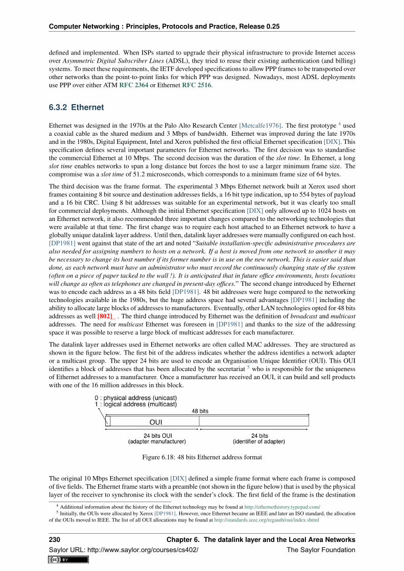
Computer Networking : Principles, Protocols and Practice, Release 0.25
defined and implemented. When ISPs started to upgrade their physical infrastructure to provide Internet accessover Asymmetric Digital Subscriber Lines (ADSL), they tried to reuse their existing authentication (and billing)systems. To meet these requirements, the IETF developed specifications to allow PPP frames to be transported overother networks than the point-to-point links for which PPP was designed. Nowadays, most ADSL deploymentsuse PPP over either ATM RFC 2364 or Ethernet RFC 2516.
6.3.2 Ethernet
Ethernet was designed in the 1970s at the Palo Alto Research Center [Metcalfe1976]. The first prototype 4 useda coaxial cable as the shared medium and 3 Mbps of bandwidth. Ethernet was improved during the late 1970sand in the 1980s, Digital Equipment, Intel and Xerox published the first official Ethernet specification [DIX]. Thisspecification defines several important parameters for Ethernet networks. The first decision was to standardisethe commercial Ethernet at 10 Mbps. The second decision was the duration of the slot time. In Ethernet, a longslot time enables networks to span a long distance but forces the host to use a larger minimum frame size. Thecompromise was a slot time of 51.2 microseconds, which corresponds to a minimum frame size of 64 bytes.
The third decision was the frame format. The experimental 3 Mbps Ethernet network built at Xerox used shortframes containing 8 bit source and destination addresses fields, a 16 bit type indication, up to 554 bytes of payloadand a 16 bit CRC. Using 8 bit addresses was suitable for an experimental network, but it was clearly too smallfor commercial deployments. Although the initial Ethernet specification [DIX] only allowed up to 1024 hosts onan Ethernet network, it also recommended three important changes compared to the networking technologies thatwere available at that time. The first change was to require each host attached to an Ethernet network to have aglobally unique datalink layer address. Until then, datalink layer addresses were manually configured on each host.[DP1981] went against that state of the art and noted “Suitable installation-specific administrative procedures arealso needed for assigning numbers to hosts on a network. If a host is moved from one network to another it maybe necessary to change its host number if its former number is in use on the new network. This is easier said thandone, as each network must have an administrator who must record the continuously changing state of the system(often on a piece of paper tacked to the wall !). It is anticipated that in future office environments, hosts locationswill change as often as telephones are changed in present-day offices.” The second change introduced by Ethernetwas to encode each address as a 48 bits field [DP1981]. 48 bit addresses were huge compared to the networkingtechnologies available in the 1980s, but the huge address space had several advantages [DP1981] including theability to allocate large blocks of addresses to manufacturers. Eventually, other LAN technologies opted for 48 bitsaddresses as well [802]_ . The third change introduced by Ethernet was the definition of broadcast and multicastaddresses. The need for multicast Ethernet was foreseen in [DP1981] and thanks to the size of the addressingspace it was possible to reserve a large block of multicast addresses for each manufacturer.
The datalink layer addresses used in Ethernet networks are often called MAC addresses. They are structured asshown in the figure below. The first bit of the address indicates whether the address identifies a network adapteror a multicast group. The upper 24 bits are used to encode an Organisation Unique Identifier (OUI). This OUIidentifies a block of addresses that has been allocated by the secretariat 5 who is responsible for the uniquenessof Ethernet addresses to a manufacturer. Once a manufacturer has received an OUI, it can build and sell productswith one of the 16 million addresses in this block.
Figure 6.18: 48 bits Ethernet address format
The original 10 Mbps Ethernet specification [DIX] defined a simple frame format where each frame is composedof five fields. The Ethernet frame starts with a preamble (not shown in the figure below) that is used by the physicallayer of the receiver to synchronise its clock with the sender’s clock. The first field of the frame is the destination
4 Additional information about the history of the Ethernet technology may be found at http://ethernethistory.typepad.com/5 Initially, the OUIs were allocated by Xerox [DP1981]. However, once Ethernet became an IEEE and later an ISO standard, the allocation
of the OUIs moved to IEEE. The list of all OUI allocations may be found at http://standards.ieee.org/regauth/oui/index.shtml
230 Chapter 6. The datalink layer and the Local Area NetworksSaylor URL: http://www.saylor.org/courses/cs402/ The Saylor Foundation

Computer Networking : Principles, Protocols and Practice, Release 0.25
address. As this address is placed at the beginning of the frame, an Ethernet interface can quickly verify whetherit is the frame recipient and if not, cancel the processing of the arriving frame. The second field is the sourceaddress. While the destination address can be either a unicast or a multicast/broadcast address, the source addressmust always be a unicast address. The third field is a 16 bits integer that indicates which type of network layerpacket is carried inside the frame. This field is often called the EtherType. Frequently used EtherType values 6
include 0x0800 for IPv4, 0x86DD for IPv6 7 and 0x806 for the Address Resolution Protocol (ARP).
The fourth part of the Ethernet frame is the payload. The minimum length of the payload is 46 bytes to ensure aminimum frame size, including the header of 512 bits. The Ethernet payload cannot be longer than 1500 bytes.This size was found reasonable when the first Ethernet specification was written. At that time, Xerox had beenusing its experimental 3 Mbps Ethernet that offered 554 bytes of payload and RFC 1122 required a minimumMTU of 572 bytes for IPv4. 1500 bytes was large enough to support these needs without forcing the networkadapters to contain overly large memories. Furthermore, simulations and measurement studies performed inEthernet networks revealed that CSMA/CD was able to achieve a very high utilization. This is illustrated in thefigure below based on [SH1980], which shows the channel utilization achieved in Ethernet networks containingdifferent numbers of hosts that are sending frames of different sizes.
Figure 6.19: Impact of the frame length on the maximum channel utilisation [SH1980]
The last field of the Ethernet frame is a 32 bit Cyclical Redundancy Check (CRC). This CRC is able to catch amuch larger number of transmission errors than the Internet checksum used by IP, UDP and TCP [SGP98]. Theformat of the Ethernet frame is shown below.
Note: Where should the CRC be located in a frame ?
The transport and datalink layers usually chose different strategies to place their CRCs or checksums. Transportlayer protocols usually place their CRCs or checksums in the segment header. Datalink layer protocols sometimesplace their CRC in the frame header, but often in a trailer at the end of the frame. This choice reflects implementa-tion assumptions, but also influences performance RFC 893. When the CRC is placed in the trailer, as in Ethernet,the datalink layer can compute it while transmitting the frame and insert it at the end of the transmission. All Eth-ernet interfaces use this optimisation today. When the checksum is placed in the header, as in a TCP segment,it is impossible for the network interface to compute it while transmitting the segment. Some network interfacesprovide hardware assistance to compute the TCP checksum, but this is more complex than if the TCP checksumwere placed in the trailer 8.
6 The official list of all assigned Ethernet type values is available from http://standards.ieee.org/regauth/ethertype/eth.txt7 The attentive reader may question the need for different EtherTypes for IPv4 and IPv6 while the IP header already contains a version
field that can be used to distinguish between IPv4 and IPv6 packets. Theoretically, IPv4 and IPv6 could have used the same EtherType.Unfortunately, developers of the early IPv6 implementations found that some devices did not check the version field of the IPv4 packets thatthey received and parsed frames whose EtherType was set to 0x0800 as IPv4 packets. Sending IPv6 packets to such devices would have causeddisruptions. To avoid this problem, the IETF decided to apply for a distinct EtherType value for IPv6.
8 These network interfaces compute the TCP checksum while a segment is transferred from the host memory to the network interface
6.3. Datalink layer technologies 231Saylor URL: http://www.saylor.org/courses/cs402/ The Saylor Foundation

Computer Networking : Principles, Protocols and Practice, Release 0.25
Figure 6.20: Ethernet DIX frame format
The Ethernet frame format shown above is specified in [DIX]. This is the format used to send both IPv4 RFC 894and IPv6 packets RFC 2464. After the publication of [DIX], the Institute of Electrical and Electronic Engineers(IEEE) began to standardise several Local Area Network technologies. IEEE worked on several LAN technolo-gies, starting with Ethernet, Token Ring and Token Bus. These three technologies were completely different, butthey all agreed to use the 48 bits MAC addresses specified initially for Ethernet [802]_ . While developing itsEthernet standard [802.3], the IEEE 802.3 working group was confronted with a problem. Ethernet mandated aminimum payload size of 46 bytes, while some companies were looking for a LAN technology that could trans-parently transport short frames containing only a few bytes of payload. Such a frame can be sent by an Ethernethost by padding it to ensure that the payload is at least 46 bytes long. However since the Ethernet header [DIX]does not contain a length field, it is impossible for the receiver to determine how many useful bytes were placedinside the payload field. To solve this problem, the IEEE decided to replace the Type field of the Ethernet [DIX]header with a length field 9. This Length field contains the number of useful bytes in the frame payload. The pay-load must still contain at least 46 bytes, but padding bytes are added by the sender and removed by the receiver.In order to add the Length field without significantly changing the frame format, IEEE had to remove the Typefield. Without this field, it is impossible for a receiving host to identify the type of network layer packet inside areceived frame. To solve this new problem, IEEE developed a completely new sublayer called the Logical LinkControl [802.2]. Several protocols were defined in this sublayer. One of them provided a slightly different versionof the Type field of the original Ethernet frame format. Another contained acknowledgements and retransmissionsto provide a reliable service... In practice, [802.2] is never used to support IP in Ethernet networks. The figurebelow shows the official [802.3] frame format.
Figure 6.21: Ethernet 802.3 frame format
Note: What is the Ethernet service ?
An Ethernet network provides an unreliable connectionless service. It supports three different transmission modes
[SH2004].9 Fortunately, IEEE was able to define the [802.3] frame format while maintaining backward compatibility with the Ethernet [DIX] frame
format. The trick was to only assign values above 1500 as EtherType values. When a host receives a frame, it can determine whether theframe’s format by checking its EtherType/Length field. A value lower smaller than 1501 is clearly a length indicator and thus an [802.3] frame.A value larger than 1501 can only be type and thus a [DIX] frame.
232 Chapter 6. The datalink layer and the Local Area NetworksSaylor URL: http://www.saylor.org/courses/cs402/ The Saylor Foundation

Computer Networking : Principles, Protocols and Practice, Release 0.25
[unicast, multicast and broadcast. While the Ethernet service is unreliable in theory, a good Ethernetnetwork should, in practice, provide a service that :]
• delivers frames to their destination with a very high probability of successful delivery
• does not reorder the transmitted frames
The first property is a consequence of the utilisation of CSMA/CD. The second property is a consequence ofthe physical organisation of the Ethernet network as a shared bus. These two properties are important and allevolutions of the Ethernet technology have preserved them.
Several physical layers have been defined for Ethernet networks. The first physical layer, usually called 10Base5,provided 10 Mbps over a thick coaxial cable. The characteristics of the cable and the transceivers that were usedthen enabled the utilisation of 500 meter long segments. A 10Base5 network can also include repeaters betweensegments.
The second physical layer was 10Base2. This physical layer used a thin coaxial cable that was easier to installthan the 10Base5 cable, but could not be longer than 185 meters. A 10BaseF physical layer was also definedto transport Ethernet over point-to-point optical links. The major change to the physical layer was the supportof twisted pairs in the 10BaseT specification. Twisted pair cables are traditionally used to support the telephoneservice in office buildings. Most office buildings today are equipped with structured cabling. Several twisted paircables are installed between any room and a central telecom closet per building or per floor in large buildings.These telecom closets act as concentration points for the telephone service but also for LANs.
The introduction of the twisted pairs led to two major changes to Ethernet. The first change concerns the physicaltopology of the network. 10Base2 and 10Base5 networks are shared buses, the coaxial cable typically passesthrough each room that contains a connected computer. A 10BaseT network is a star-shaped network. All thedevices connected to the network are attached to a twisted pair cable that ends in the telecom closet. Froma maintenance perspective, this is a major improvement. The cable is a weak point in 10Base2 and 10Base5networks. Any physical damage on the cable broke the entire network and when such a failure occurred, thenetwork administrator had to manually check the entire cable to detect where it was damaged. With 10BaseT,when one twisted pair is damaged, only the device connected to this twisted pair is affected and this does notaffect the other devices. The second major change introduced by 10BaseT was that is was impossible to build a10BaseT network by simply connecting all the twisted pairs together. All the twisted pairs must be connected toa relay that operates in the physical layer. This relay is called an Ethernet hub. A hub is thus a physical layerrelay that receives an electrical signal on one of its interfaces, regenerates the signal and transmits it over all itsother interfaces. Some hubs are also able to convert the electrical signal from one physical layer to another (e.g.10BaseT to 10Base2 conversion).
Figure 6.22: Ethernet hubs in the reference model
Computers can directly be attached to Ethernet hubs. Ethernet hubs themselves can be attached to other Ethernethubs to build a larger network. However, some important guidelines must be followed when building a complexnetwork with hubs. First, the network topology must be a tree. As hubs are relays in the physical layer, addinga link between Hub2 and Hub3 in the network below would create an electrical shortcut that would completelydisrupt the network. This implies that there cannot be any redundancy in a hub-based network. A failure of ahub or of a link between two hubs would partition the network into two isolated networks. Second, as hubs arerelays in the physical layer, collisions can happen and must be handled by CSMA/CD as in a 10Base5 network.This implies that the maximum delay between any pair of devices in the network cannot be longer than the 51.2
6.3. Datalink layer technologies 233Saylor URL: http://www.saylor.org/courses/cs402/ The Saylor Foundation

Computer Networking : Principles, Protocols and Practice, Release 0.25
microseconds slot time. If the delay is longer, collisions between short frames may not be correctly detected. Thisconstraint limits the geographical spread of 10BaseT networks containing hubs.
Figure 6.23: A hierarchical Ethernet network composed of hubs
In the late 1980s, 10 Mbps became too slow for some applications and network manufacturers developed severalLAN technologies that offered higher bandwidth, such as the 100 Mbps FDDI LAN that used optical fibers. As thedevelopment of 10Base5, 10Base2 and 10BaseT had shown that Ethernet could be adapted to different physicallayers, several manufacturers started to work on 100 Mbps Ethernet and convinced IEEE to standardise this newtechnology that was initially called Fast Ethernet. Fast Ethernet was designed under two constraints. First,Fast Ethernet had to support twisted pairs. Although it was easier from a physical layer perspective to supporthigher bandwidth on coaxial cables than on twisted pairs, coaxial cables were a nightmare from deploymentand maintenance perspectives. Second, Fast Ethernet had to be perfectly compatible with the existing 10 MbpsEthernets to allow Fast Ethernet technology to be used initially as a backbone technology to interconnect 10Mbps Ethernet networks. This forced Fast Ethernet to use exactly the same frame format as 10 Mbps Ethernet.This implied that the minimum Fast Ethernet frame size remained at 512 bits. To preserve CSMA/CD with thisminimum frame size and 100 Mbps instead of 10 Mbps, the duration of the slot time was decreased to 5.12microseconds.
The evolution of Ethernet did not stop. In 1998, the IEEE published a first standard to provide Gigabit Ethernetover optical fibers. Several other types of physical layers were added afterwards. The 10 Gigabit Ethernet standardappeared in 2002. Work is ongoing to develop standards for 40 Gigabit and 100 Gigabit Ethernet and some arethinking about Terabit Ethernet. The table below lists the main Ethernet standards. A more detailed list may befound at http://en.wikipedia.org/wiki/Ethernet_physical_layer
Standard Comments10Base5 Thick coaxial cable, 500m10Base2 Thin coaxial cable, 185m10BaseT Two pairs of category 3+ UTP10Base-F 10 Mb/s over optical fiber100Base-Tx Category 5 UTP or STP, 100 m maximum100Base-FX Two multimode optical fiber, 2 km maximum1000Base-CX Two pairs shielded twisted pair, 25m maximum1000Base-SX Two multimode or single mode optical fibers with lasers10 Gbps Optical fiber but also Category 6 UTP40-100 Gbps Being developed, standard expected in 2010
Ethernet Switches
Increasing the physical layer bandwidth as in Fast Ethernet was only one of the solutions to improve the perfor-mance of Ethernet LANs. A second solution was to replace the hubs with more intelligent devices. As Ethernethubs operate in the physical layer, they can only regenerate the electrical signal to extend the geographical reach
234 Chapter 6. The datalink layer and the Local Area NetworksSaylor URL: http://www.saylor.org/courses/cs402/ The Saylor Foundation

Computer Networking : Principles, Protocols and Practice, Release 0.25
of the network. From a performance perspective, it would be more interesting to have devices that operate in thedatalink layer and can analyse the destination address of each frame and forward the frames selectively on the linkthat leads to the destination. Such devices are usually called Ethernet switches 10. An Ethernet switch is a relaythat operates in the datalink layer as is illustrated in the figure below.
Figure 6.24: Ethernet switches and the reference model
An Ethernet switch understands the format of the Ethernet frames and can selectively forward frames over eachinterface. For this, each Ethernet switch maintains a MAC address table. This table contains, for each MACaddress known by the switch, the identifier of the switch’s port over which a frame sent towards this address mustbe forwarded to reach its destination. This is illustrated below with the MAC address table of the bottom switch.When the switch receives a frame destined to address B, it forwards the frame on its South port. If it receives aframe destined to address D, it forwards it only on its North port.
Figure 6.25: Operation of Ethernet switches
One of the selling points of Ethernet networks is that, thanks to the utilisation of 48 bits MAC addresses, anEthernet LAN is plug and play at the datalink layer. When two hosts are attached to the same Ethernet segmentor hub, they can immediately exchange Ethernet frames without requiring any configuration. It is important toretain this plug and play capability for Ethernet switches as well. This implies that Ethernet switches must beable to build their MAC address table automatically without requiring any manual configuration. This automaticconfiguration is performed by the the MAC address learning algorithm that runs on each Ethernet switch. Thisalgorithm extracts the source address of the received frames and remembers the port over which a frame from
10 The first Ethernet relays that operated in the datalink layers were called bridges. In practice, the main difference between switches andbridges is that bridges were usually implemented in software while switches are hardware-based devices. Throughout this text, we always useswitch when referring to a relay in the datalink layer, but you might still see the word bridge.
6.3. Datalink layer technologies 235Saylor URL: http://www.saylor.org/courses/cs402/ The Saylor Foundation

Computer Networking : Principles, Protocols and Practice, Release 0.25
each source Ethernet address has been received. This information is inserted into the MAC address table that theswitch uses to forward frames. This allows the switch to automatically learn the ports that it can use to reach eachdestination address, provided that this host has previously sent at least one frame. This is not a problem sincemost upper layer protocols use acknowledgements at some layer and thus even an Ethernet printer sends Ethernetframes as well.
The pseudo-code below details how an Ethernet switch forwards Ethernet frames. It first updates its MAC addresstable with the source address of the frame. The MAC address table used by some switches also contains atimestamp that is updated each time a frame is received from each known source address. This timestamp isused to remove from the MAC address table entries that have not been active during the last n minutes. This limitsthe growth of the MAC address table, but also allows hosts to move from one port to another. The switch uses itsMAC address table to forward the received unicast frame. If there is an entry for the frame’s destination addressin the MAC address table, the frame is forwarded selectively on the port listed in this entry. Otherwise, the switchdoes not know how to reach the destination address and it must forward the frame on all its ports except the portfrom which the frame has been received. This ensures that the frame will reach its destination, at the expense ofsome unnecessary transmissions. These unnecessary transmissions will only last until the destination has sent itsfirst frame. Multicast and Broadcast frames are also forwarded in a similar way.
# Arrival of frame F on port P# Table : MAC address table dictionary : addr->port# Ports : list of all ports on the switchsrc=F.SourceAddressdst=F.DestinationAddressTable[src]=P #src heard on port Pif isUnicast(dst) :
if dst in Table:ForwardFrame(F,Table[dst])
else:for o in Ports :
if o!= P : ForwardFrame(F,o)else:
# multicast or broadcast destinationfor o in Ports :
if o!= P : ForwardFrame(F,o)
Note: Security issues with Ethernet hubs and switches
From a security perspective, Ethernet hubs have the same drawbacks as the older coaxial cable. A host attached toa hub will be able to capture all the frames exchanged between any pair of hosts attached to the same hub. Ethernetswitches are much better from this perspective thanks to the selective forwarding, a host will usually only receivethe frames destined to itself as well as the multicast, broadcast and unknown frames. However, this does not implythat switches are completely secure. There are, unfortunately, attacks against Ethernet switches. From a securityperspective, the MAC address table is one of the fragile elements of an Ethernet switch. This table has a fixedsize. Some low-end switches can store a few tens or a few hundreds of addresses while higher-end switches canstore tens of thousands of addresses or more. From a security point of view, a limited resource can be the targetof Denial of Service attacks. Unfortunately, such attacks are also possible on Ethernet switches. A malicioushost could overflow the MAC address table of the switch by generating thousands of frames with random sourceaddresses. Once the MAC address table is full, the switch needs to broadcast all the frames that it receives. Atthis point, an attacker will receive unicast frames that are not destined to its address. The ARP attack discussed inthe previous chapter could also occur with Ethernet switches [Vyncke2007]. Recent switches implement severaltypes of defences against these attacks, but they need to be carefully configured by the network administrator. See[Vyncke2007] for a detailed discussion on security issues with Ethernet switches.
The MAC address learning algorithm combined with the forwarding algorithm work well in a tree-shaped networksuch as the one shown above. However, to deal with link and switch failures, network administrators often addredundant links to ensure that their network remains connected even after a failure. Let us consider what happensin the Ethernet network shown in the figure below.
When all switches boot, their MAC address table is empty. Assume that host A sends a frame towards host C.Upon reception of this frame, switch1 updates its MAC address table to remember that address A is reachable
236 Chapter 6. The datalink layer and the Local Area NetworksSaylor URL: http://www.saylor.org/courses/cs402/ The Saylor Foundation

Computer Networking : Principles, Protocols and Practice, Release 0.25
Figure 6.26: Ethernet switches in a loop
via its West port. As there is no entry for address C in switch1’s MAC address table, the frame is forwarded toboth switch2 and switch3. When switch2 receives the frame, its updates its MAC address table for address Aand forwards the frame to host C as well as to switch3. switch3 has thus received two copies of the same frame.As switch3 does not know how to reach the destination address, it forwards the frame received from switch1 toswitch2 and the frame received from switch2 to switch1... The single frame sent by host A will be continuouslyduplicated by the switches until their MAC address table contains an entry for address C. Quickly, all the availablelink bandwidth will be used to forward all the copies of this frame. As Ethernet does not contain any TTL orHopLimit, this loop will never stop.
The MAC address learning algorithm allows switches to be plug-and-play. Unfortunately, the loops that arisewhen the network topology is not a tree are a severe problem. Forcing the switches to only be used in tree-shapednetworks as hubs would be a severe limitation. To solve this problem, the inventors of Ethernet switches havedeveloped the Spanning Tree Protocol. This protocol allows switches to automatically disable ports on Ethernetswitches to ensure that the network does not contain any cycle that could cause frames to loop forever.
The Spanning Tree Protocol (802.1d)
The Spanning Tree Protocol (STP), proposed in [Perlman1985], is a distributed protocol that is used by switchesto reduce the network topology to a spanning tree, so that there are no cycles in the topology. For example,consider the network shown in the figure below. In this figure, each bold line corresponds to an Ethernet to whichtwo Ethernet switches are attached. This network contains several cycles that must be broken to allow Ethernetswitches that are using the MAC address learning algorithm to exchange frames.
In this network, the STP will compute the following spanning tree. Switch1 will be the root of the tree. All theinterfaces of Switch1, Switch2 and Switch7 are part of the spanning tree. Only the interface connected to LANBwill be active on Switch9. LANH will only be served by Switch7 and the port of Switch44 on LANG will bedisabled. A frame originating on LANB and destined for LANA will be forwarded by Switch7 on LANC, then bySwitch1 on LANE, then by Switch44 on LANF and eventually by Switch2 on LANA.
Switches running the Spanning Tree Protocol exchange BPDUs. These BPDUs are always sent as frames withdestination MAC address as the ALL_BRIDGES reserved multicast MAC address. Each switch has a unique 64bit identifier. To ensure uniqueness, the lower 48 bits of the identifier are set to the unique MAC address allocatedto the switch by its manufacturer. The high order 16 bits of the switch identifier can be configured by the networkadministrator to influence the topology of the spanning tree. The default value for these high order bits is 32768.
6.3. Datalink layer technologies 237Saylor URL: http://www.saylor.org/courses/cs402/ The Saylor Foundation

Computer Networking : Principles, Protocols and Practice, Release 0.25
Figure 6.27: Spanning tree computed in a switched Ethernet network
The switches exchange BPDUs to build the spanning tree. Intuitively, the spanning tree is built by first selectingthe switch with the smallest identifier as the root of the tree. The branches of the spanning tree are then composedof the shortest paths that allow all of the switches that compose the network to be reached. The BPDUs exchangedby the switches contain the following information :
• the identifier of the root switch (R)
• the cost of the shortest path between the switch that sent the BPDU and the root switch (c)
• the identifier of the switch that sent the BPDU (T)
• the number of the switch port over which the BPDU was sent (p)
We will use the notation <R,c,T,p> to represent a BPDU whose root identifier is R, cost is c and that was senton the port p of switch T. The construction of the spanning tree depends on an ordering relationship among theBPDUs. This ordering relationship could be implemented by the python function below.
# returns True if bpdu b1 is better than bpdu b2def better( b1, b2) :
return ( (b1.R < b2.R) or( (b1.R==b2.R) and (b1.c<b2.c) ) or( (b1.R==b2.R) and (b1.c==b2.c) and (b1.T<b2.T) ) or( (b1.R==b2.R) and (b1.c==b2.c) and (b1.T==b2.T) and (b1.p<b2.p) ) )
In addition to the identifier discussed above, the network administrator can also configure a cost to be associatedto each switch port. Usually, the cost of a port depends on its bandwidth and the [802.1d] standard recommendsthe values below. Of course, the network administrator may choose other values. We will use the notation cost[p]to indicate the cost associated to port p in this section.
Bandwidth Cost10 Mbps 2000000100 Mbps 2000001 Gbps 2000010 Gbps 2000100 Gbps 200
The Spanning Tree Protocol uses its own terminology that we illustrate in the figure above. A switch port can bein three different states : Root, Designated and Blocked. All the ports of the root switch are in the Designatedstate. The state of the ports on the other switches is determined based on the BPDU received on each port.
The Spanning Tree Protocol uses the ordering relationship to build the spanning tree. Each switch listens toBPDUs on its ports. When BPDU=<R,c,T,p> is received on port q, the switch computes the port’s priorityvector: V[q]=<R,c+cost[q],T,p,q> , where cost[q] is the cost associated to the port over which the BPDU was
238 Chapter 6. The datalink layer and the Local Area NetworksSaylor URL: http://www.saylor.org/courses/cs402/ The Saylor Foundation

Computer Networking : Principles, Protocols and Practice, Release 0.25
received. The switch stores in a table the last priority vector received on each port. The switch then compares itsown identifier with the smallest root identifier stored in this table. If its own identifier is smaller, then the switchis the root of the spanning tree and is, by definition, at a distance 0 of the root. The BPDU of the switch is then<R,0,R,p>, where R is the switch identifier and p will be set to the port number over which the BPDU is sent.Otherwise, the switch chooses the best priority vector from its table, bv=<R,c,T,p>. The port over which this bestpriority vector was learned is the switch port that is closest to the root switch. This port becomes the Root port ofthe switch. There is only one Root port per switch. The switch can then compute its BPDU as BPDU=<R,c,S,p>, where R is the root identifier, c the cost of the best priority vector, S the identifier of the switch and p will bereplaced by the number of the port over which the BPDU will be sent. The switch can then determine the stateof all its ports by comparing its own BPDU with the priority vector received on each port. If the switch’s BPDUis better than the priority vector of this port, the port becomes a Designated port. Otherwise, the port becomes aBlocked port.
The state of each port is important when considering the transmission of BPDUs. The root switch regularly sendsits own BPDU over all of its (Designated) ports. This BPDU is received on the Root port of all the switches thatare directly connected to the root switch. Each of these switches computes its own BPDU and sends this BPDUover all its Designated ports. These BPDUs are then received on the Root port of downstream switches, whichthen compute their own BPDU, etc. When the network topology is stable, switches send their own BPDU onall their Designated ports, once they receive a BPDU on their Root port. No BPDU is sent on a Blocked port.Switches listen for BPDUs on their Blocked and Designated ports, but no BPDU should be received over theseports when the topology is stable. The utilisation of the ports for both BPDUs and data frames is summarised inthe table below.
Port state Receives BPDUs Sends BPDU Handles data framesBlocked yes no noRoot yes no yesDesignated yes yes yes
To illustrate the operation of the Spanning Tree Protocol, let us consider the simple network topology in the figurebelow.
Figure 6.28: A simple Spanning tree computed in a switched Ethernet network
Assume that Switch4 is the first to boot. It sends its own BPDU=<4,0,4,?> on its two ports. When Switch1boots, it sends BPDU=<1,0,1,1>. This BPDU is received by Switch4, which updates its table and computes anew BPDU=<1,3,4,?>. Port 1 of Switch4 becomes the Root port while its second port is still in the Designatedstate.
Assume now that Switch9 boots and immediately receives Switch1 ‘s BPDU on port 1. Switch9 computes its ownBPDU=<1,1,9,?> and port 1 becomes the Root port of this switch. This BPDU is sent on port 2 of Switch9 and
6.3. Datalink layer technologies 239Saylor URL: http://www.saylor.org/courses/cs402/ The Saylor Foundation

Computer Networking : Principles, Protocols and Practice, Release 0.25
reaches Switch4. Switch4 compares the priority vector built from this BPDU (i.e. <1,2,9,2>) and notices that it isbetter than Switch4 ‘s BPDU=<1,3,4,2>. Thus, port 2 becomes a Blocked port on Switch4.
During the computation of the spanning tree, switches discard all received data frames, as at that time the networktopology is not guaranteed to be loop-free. Once that topology has been stable for some time, the switches againstart to use the MAC learning algorithm to forward data frames. Only the Root and Designated ports are usedto forward data frames. Switches discard all the data frames received on their Blocked ports and never forwardframes on these ports.
Switches, ports and links can fail in a switched Ethernet network. When a failure occurs, the switches must beable to recompute the spanning tree to recover from the failure. The Spanning Tree Protocol relies on regulartransmissions of the BPDUs to detect these failures. A BPDU contains two additional fields : the Age of theBPDU and the Maximum Age. The Age contains the amount of time that has passed since the root switch initiallyoriginated the BPDU. The root switch sends its BPDU with an Age of zero and each switch that computes its ownBPDU increments its Age by one. The Age of the BPDUs stored on a switch’s table is also incremented everysecond. A BPDU expires when its Age reaches the Maximum Age. When the network is stable, this does nothappen as BPDU s are regularly sent by the root switch and downstream switches. However, if the root fails orthe network becomes partitioned, BPDU will expire and switches will recompute their own BPDU and restart theSpanning Tree Protocol. Once a topology change has been detected, the forwarding of the data frames stops asthe topology is not guaranteed to be loop-free. Additional details about the reaction to failures may be found in[802.1d]
Virtual LANs
Another important advantage of Ethernet switches is the ability to create Virtual Local Area Networks (VLANs).A virtual LAN can be defined as a set of ports attached to one or more Ethernet switches. A switch can supportseveral VLANs and it runs one MAC learning algorithm for each Virtual LAN. When a switch receives a framewith an unknown or a multicast destination, it forwards it over all the ports that belong to the same Virtual LANbut not over the ports that belong to other Virtual LANs. Similarly, when a switch learns a source address on aport, it associates it to the Virtual LAN of this port and uses this information only when forwarding frames on thisVirtual LAN.
The figure below illustrates a switched Ethernet network with three Virtual LANs. VLAN2 and VLAN3 only requirea local configuration of switch S1. Host C can exchange frames with host D, but not with hosts that are outside ofits VLAN. VLAN1 is more complex as there are ports of this VLAN on several switches. To support such VLANs,local configuration is not sufficient anymore. When a switch receives a frame from another switch, it must be ableto determine the VLAN in which the frame originated to use the correct MAC table to forward the frame. Thisis done by assigning an identifier to each Virtual LAN and placing this identifier inside the headers of the framesthat are exchanged between switches.
Figure 6.29: Virtual Local Area Networks in a switched Ethernet network
IEEE defined in the [802.1q] standard a special header to encode the VLAN identifiers. This 32 bit headerincludes a 20 bit VLAN field that contains the VLAN identifier of each frame. The format of the [802.1q] headeris described below.
The [802.1q] header is inserted immediately after the source MAC address in the Ethernet frame (i.e. before theEtherType field). The maximum frame size is increased by 4 bytes. It is encoded in 32 bits and contains four
240 Chapter 6. The datalink layer and the Local Area NetworksSaylor URL: http://www.saylor.org/courses/cs402/ The Saylor Foundation

Computer Networking : Principles, Protocols and Practice, Release 0.25
Figure 6.30: Format of the 802.1q header
fields. The Tag Protocol Identifier is set to 0x8100 to allow the receiver to detect the presence of this additionalheader. The Priority Code Point (PCP) is a three bit field that is used to support different transmission prioritiesfor the frame. Value 0 is the lowest priority and value 7 the highest. Frames with a higher priority can expect tobe forwarded earlier than frames having a lower priority. The C bit is used for compatibility between Ethernet andToken Ring networks. The last 12 bits of the 802.1q header contain the VLAN identifier. Value 0 indicates thatthe frame does not belong to any VLAN while value 0xFFF is reserved. This implies that 4094 different VLANidentifiers can be used in an Ethernet network.
6.3.3 802.11 wireless networks
The radio spectrum is a limited resource that must be shared by everyone. During most of the twentieth century,governments and international organisations have regulated most of the radio spectrum. This regulation controlsthe utilisation of the radio spectrum, in order to ensure that there are no interferences between different users.A company that wants to use a frequency range in a given region must apply for a license from the regulator.Most regulators charge a fee for the utilisation of the radio spectrum and some governments have encouragedcompetition among companies bidding for the same frequency to increase the license fees.
In the 1970s, after the first experiments with ALOHANet, interest in wireless networks grew. Many experimentswere done on and outside the ARPANet. One of these experiments was the first mobile phone , which was de-veloped and tested in 1973. This experimental mobile phone was the starting point for the first generation analogmobile phones. Given the growing demand for mobile phones, it was clear that the analog mobile phone technol-ogy was not sufficient to support a large number of users. To support more users and new services, researchers inseveral countries worked on the development of digital mobile telephones. In 1987, several European countriesdecided to develop the standards for a common cellular telephone system across Europe : the Global System forMobile Communications (GSM). Since then, the standards have evolved and more than three billion users areconnected to GSM networks today.
While most of the frequency ranges of the radio spectrum are reserved for specific applications and require aspecial licence, there are a few exceptions. These exceptions are known as the Industrial, Scientific and Medical(ISM) radio bands. These bands can be used for industrial, scientific and medical applications without requiringa licence from the regulator. For example, some radio-controlled models use the 27 MHz ISM band and somecordless telephones operate in the 915 MHz ISM. In 1985, the 2.400-2.500 GHz band was added to the list ofISM bands. This frequency range corresponds to the frequencies that are emitted by microwave ovens. Sharingthis band with licensed applications would have likely caused interferences, given the large number of microwaveovens that are used. Despite the risk of interferences with microwave ovens, the opening of the 2.400-2.500 GHzallowed the networking industry to develop several wireless network techniques to allow computers to exchangedata without using cables. In this section, we discuss in more detail the most popular one, i.e. the WiFi [802.11]family of wireless networks. Other wireless networking techniques such as BlueTooth or HiperLAN use the samefrequency range.
Today, WiFi is a very popular wireless networking technology. There are more than several hundreds of millionsof WiFi devices. The development of this technology started in the late 1980s with the WaveLAN proprietarywireless network. WaveLAN operated at 2 Mbps and used different frequency bands in different regions of theworld. In the early 1990s, the IEEE created the 802.11 working group to standardise a family of wireless networktechnologies. This working group was very prolific and produced several wireless networking standards that usedifferent frequency ranges and different physical layers. The table below provides a summary of the main 802.11standards.
6.3. Datalink layer technologies 241Saylor URL: http://www.saylor.org/courses/cs402/ The Saylor Foundation

Computer Networking : Principles, Protocols and Practice, Release 0.25
Standard Frequency Typical throughput Max bandwidth Range (m) indoor/outdoor802.11 2.4 GHz 0.9 Mbps 2 Mbps 20/100802.11a 5 GHz 23 Mbps 54 Mbps 35/120802.11b 2.4 GHz 4.3 Mbps 11 Mbps 38/140802.11g 2.4 GHz 19 Mbps 54 Mbps 38/140802.11n 2.4/5 GHz 74 Mbps 150 Mbps 70/250
When developing its family of standards, the IEEE 802.11 working group took a similar approach as the IEEE802.3 working group that developed various types of physical layers for Ethernet networks. 802.11 networks usethe CSMA/CA Medium Access Control technique described earlier and they all assume the same architecture anduse the same frame format.
The architecture of WiFi networks is slightly different from the Local Area Networks that we have discussed untilnow. There are, in practice, two main types of WiFi networks : independent or adhoc networks and infrastructurenetworks 11. An independent or adhoc network is composed of a set of devices that communicate with each other.These devices play the same role and the adhoc network is usually not connected to the global Internet. Adhocnetworks are used when for example a few laptops need to exchange information or to connect a computer with aWiFi printer.
Figure 6.31: An 802.11 independent or adhoc network
Most WiFi networks are infrastructure networks. An infrastructure network contains one or more access pointsthat are attached to a fixed Local Area Network (usually an Ethernet network) that is connected to other networkssuch as the Internet. The figure below shows such a network with two access points and four WiFi devices. EachWiFi device is associated to one access point and uses this access point as a relay to exchange frames with thedevices that are associated to another access point or reachable through the LAN.
An 802.11 access point is a relay that operates in the datalink layer like switches. The figure below represents thelayers of the reference model that are involved when a WiFi host communicates with a host attached to an Ethernetnetwork through an access point.
802.11 devices exchange variable length frames, which have a slightly different structure than the simple frameformat used in Ethernet LANs. We review the key parts of the 802.11 frames. Additional details may be foundin [802.11] and [Gast2002] . An 802.11 frame contains a fixed length header, a variable length payload thatmay contain up 2324 bytes of user data and a 32 bits CRC. Although the payload can contain up to 2324 bytes,
11 The 802.11 working group defined the basic service set (BSS) as a group of devices that communicate with each other. We continue touse network when referring to a set of devices that communicate.
242 Chapter 6. The datalink layer and the Local Area NetworksSaylor URL: http://www.saylor.org/courses/cs402/ The Saylor Foundation

Computer Networking : Principles, Protocols and Practice, Release 0.25
Figure 6.32: An 802.11 infrastructure network
Figure 6.33: An 802.11 access point
6.3. Datalink layer technologies 243Saylor URL: http://www.saylor.org/courses/cs402/ The Saylor Foundation

Computer Networking : Principles, Protocols and Practice, Release 0.25
most 802.11 deployments use a maximum payload size of 1500 bytes as they are used in infrastructure networksattached to Ethernet LANs. An 802.11 data frame is shown below.
Figure 6.34: 802.11 data frame format
The first part of the 802.11 header is the 16 bit Frame Control field. This field contains flags that indicate thetype of frame (data frame, RTS/CTS, acknowledgement, management frames, etc), whether the frame is sent toor from a fixed LAN, etc [802.11]. The Duration is a 16 bit field that is used to reserve the transmission channel.In data frames, the Duration field is usually set to the time required to transmit one acknowledgement frame aftera SIFS delay. Note that the Duration field must be set to zero in multicast and broadcast frames. As these framesare not acknowledged, there is no need to reserve the transmission channel after their transmission. The Sequencecontrol field contains a 12 bits sequence number that is incremented for each data frame.
The astute reader may have noticed that the 802.11 data frames contain three 48-bits address fields 12 . This issurprising compared to other protocols in the network and datalink layers whose headers only contain a source anda destination address. The need for a third address in the 802.11 header comes from the infrastructure networks. Insuch a network, frames are usually exchanged between routers and servers attached to the LAN and WiFi devicesattached to one of the access points. The role of the three address fields is specified by bit flags in the FrameControl field.
When a frame is sent from a WiFi device to a server attached to the same LAN as the access point, the first addressof the frame is set to the MAC address of the access point, the second address is set to the MAC address of thesource WiFi device and the third address is the address of the final destination on the LAN. When the serverreplies, it sends an Ethernet frame whose source address is its MAC address and the destination address is theMAC address of the WiFi device. This frame is captured by the access point that converts the Ethernet header intoan 802.11 frame header. The 802.11 frame sent by the access point contains three addresses : the first address isthe MAC address of the destination WiFi device, the second address is the MAC address of the access point andthe third address the MAC address of the server that sent the frame.
802.11 control frames are simpler than data frames. They contain a Frame Control, a Duration field and one ortwo addresses. The acknowledgement frames are very small. They only contain the address of the destination ofthe acknowledgement. There is no source address and no Sequence Control field in the acknowledgement frames.This is because the acknowledgement frame can easily be associated to the previous frame that it acknowledges.Indeed, each unicast data frame contains a Duration field that is used to reserve the transmission channel to ensurethat no collision will affect the acknowledgement frame. The Sequence Control field is mainly used by the receiverto remove duplicate frames. Duplicate frames are detected as follows. Each data frame contains a 12 bits SequenceControl field and the Frame Control field contains the Retry bit flag that is set when a frame is transmitted. Each802.11 receiver stores the most recent sequence number received from each source address in frames whose Retrybit is reset. Upon reception of a frame with the Retry bit set, the receiver verifies its sequence number to determinewhether it is a duplicated frame or not.
802.11 RTS/CTS frames are used to reserve the transmission channel, in order to transmit one data frame and itsacknowledgement. The RTS frames contain a Duration and the transmitter and receiver addresses. The Duration
12 In fact, the [802.11] frame format contains a fourth optional address field. This fourth address is only used when an 802.11 wirelessnetwork is used to interconnect bridges attached to two classical LAN networks.
244 Chapter 6. The datalink layer and the Local Area NetworksSaylor URL: http://www.saylor.org/courses/cs402/ The Saylor Foundation
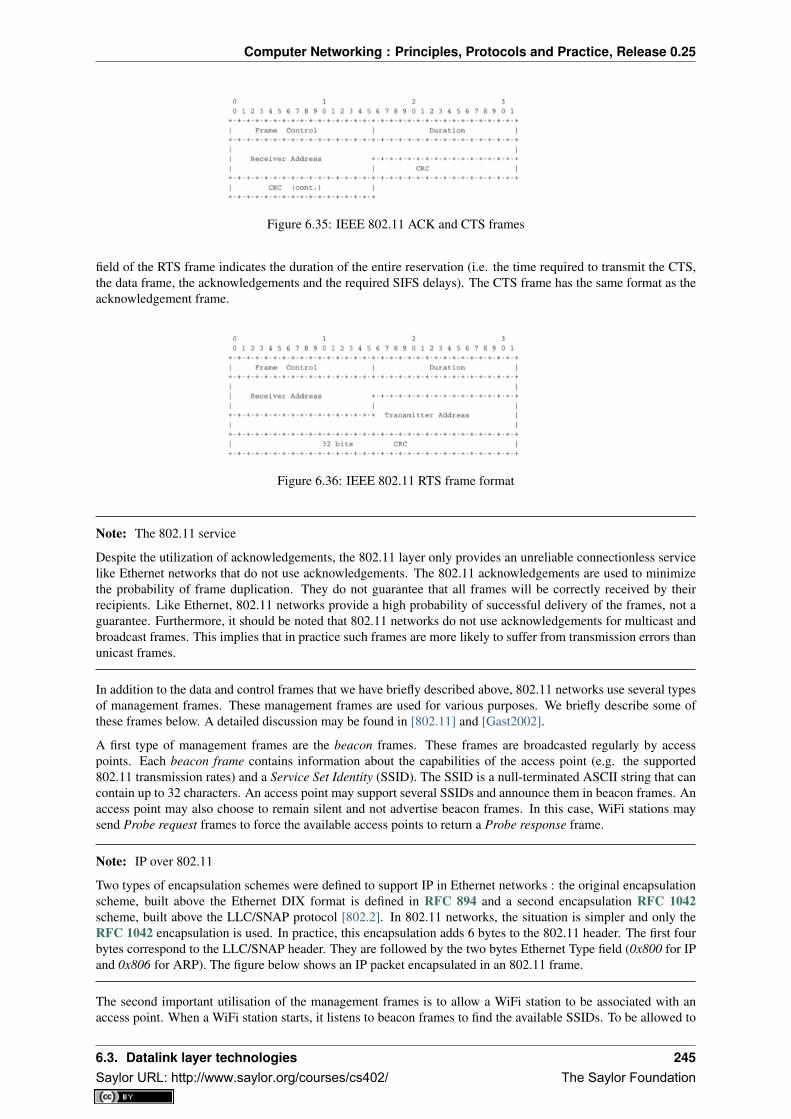
Computer Networking : Principles, Protocols and Practice, Release 0.25
Figure 6.35: IEEE 802.11 ACK and CTS frames
field of the RTS frame indicates the duration of the entire reservation (i.e. the time required to transmit the CTS,the data frame, the acknowledgements and the required SIFS delays). The CTS frame has the same format as theacknowledgement frame.
Figure 6.36: IEEE 802.11 RTS frame format
Note: The 802.11 service
Despite the utilization of acknowledgements, the 802.11 layer only provides an unreliable connectionless servicelike Ethernet networks that do not use acknowledgements. The 802.11 acknowledgements are used to minimizethe probability of frame duplication. They do not guarantee that all frames will be correctly received by theirrecipients. Like Ethernet, 802.11 networks provide a high probability of successful delivery of the frames, not aguarantee. Furthermore, it should be noted that 802.11 networks do not use acknowledgements for multicast andbroadcast frames. This implies that in practice such frames are more likely to suffer from transmission errors thanunicast frames.
In addition to the data and control frames that we have briefly described above, 802.11 networks use several typesof management frames. These management frames are used for various purposes. We briefly describe some ofthese frames below. A detailed discussion may be found in [802.11] and [Gast2002].
A first type of management frames are the beacon frames. These frames are broadcasted regularly by accesspoints. Each beacon frame contains information about the capabilities of the access point (e.g. the supported802.11 transmission rates) and a Service Set Identity (SSID). The SSID is a null-terminated ASCII string that cancontain up to 32 characters. An access point may support several SSIDs and announce them in beacon frames. Anaccess point may also choose to remain silent and not advertise beacon frames. In this case, WiFi stations maysend Probe request frames to force the available access points to return a Probe response frame.
Note: IP over 802.11
Two types of encapsulation schemes were defined to support IP in Ethernet networks : the original encapsulationscheme, built above the Ethernet DIX format is defined in RFC 894 and a second encapsulation RFC 1042scheme, built above the LLC/SNAP protocol [802.2]. In 802.11 networks, the situation is simpler and only theRFC 1042 encapsulation is used. In practice, this encapsulation adds 6 bytes to the 802.11 header. The first fourbytes correspond to the LLC/SNAP header. They are followed by the two bytes Ethernet Type field (0x800 for IPand 0x806 for ARP). The figure below shows an IP packet encapsulated in an 802.11 frame.
The second important utilisation of the management frames is to allow a WiFi station to be associated with anaccess point. When a WiFi station starts, it listens to beacon frames to find the available SSIDs. To be allowed to
6.3. Datalink layer technologies 245Saylor URL: http://www.saylor.org/courses/cs402/ The Saylor Foundation

Computer Networking : Principles, Protocols and Practice, Release 0.25
Figure 6.37: IP over IEEE 802.11
send and receive frames via an access point, a WiFi station must be associated to this access point. If the accesspoint does not use any security mechanism to secure the wireless transmission, the WiFi station simply sends anAssociation request frame to its preferred access point (usually the access point that it receives with the strongestradio signal). This frame contains some parameters chosen by the WiFi station and the SSID that it requests tojoin. The access point replies with an Association response frame if it accepts the WiFI station.
6.4 Summary
In this chapter, we first explained the principles of the datalink layer. There are two types of datalink layers : thoseused over point-to-point links and those used over Local Area Networks. On point-to-point links, the datalink layermust at least provide a framing technique, but some datalink layer protocols also include reliability mechanismssuch as those used in the transport layer. We have described the Point-to-Point Protocol that is often used overpoint-to-point links in the Internet.
Local Area Networks pose a different problem since several devices share the same transmission channel. In thiscase, a Medium Access Control algorithm is necessary to regulate the access to the transmission channel becausewhenever two devices transmit at the same time a collision occurs and none of these frames can be decodedby their recipients. There are two families of MAC algorithms. The statistical or optimistic MAC algorithmsreduce the probability of collisions but do not completely prevent them. With such algorithms, when a collisionoccurs, the collided frames must be retransmitted. We have described the operation of the ALOHA, CSMA,CSMA/CD and CSMA/CA MAC algorithms. Deterministic or pessimistic MAC algorithms avoid all collisions.We have described the Token Ring MAC where stations exchange a token to regulate the access to the transmissionchannel.
Finally, we have described in more detail two successful Local Area Network technologies : Ethernet and WiFi.Ethernet is now the de facto LAN technology. We have analysed the evolution of Ethernet including the operationof hubs and switches. We have also described the Spanning Tree Protocol that must be used when switchesare interconnected. For the last few years, WiFi became the de facto wireless technology at home and insideenterprises. We have explained the operation of WiFi networks and described the main 802.11 frames.
6.5 Exercises
1. Consider the switched network shown in the figure below. What is the spanning tree that will be computedby 802.1d in this network assuming that all links have a unit cost ? Indicate the state of each port.
2. Consider the switched network shown in the figure above. In this network, assume that the LAN betweenswitches 3 and 12 fails. How should the switches update their port/address tables after the link failure ?
3. Many enterprise networks are organized with a set of backbone devices interconnected by using a full meshof links as shown in the figure below. In this network, what are the benefits and drawbacks of using Ethernet
246 Chapter 6. The datalink layer and the Local Area NetworksSaylor URL: http://www.saylor.org/courses/cs402/ The Saylor Foundation

Computer Networking : Principles, Protocols and Practice, Release 0.25
Figure 6.38: A small network composed of Ethernet switches
switches and IP routers running OSPF ?
Figure 6.39: A typical enterprise backbone network
4. Most commercial Ethernet switches are able to run the Spanning tree protocol independently on eachVLAN. What are the benefits of using per-VLAN spanning trees ?
6.5. Exercises 247Saylor URL: http://www.saylor.org/courses/cs402/ The Saylor Foundation

Computer Networking : Principles, Protocols and Practice, Release 0.25
248 Chapter 6. The datalink layer and the Local Area NetworksSaylor URL: http://www.saylor.org/courses/cs402/ The Saylor Foundation

CHAPTER 7
Glossary
AIMD Additive Increase, Multiplicative Decrease. A rate adaption algorithm used notably by TCP where a hostadditively increases its transmission rate when the network is not congested and multiplicatively decreaseswhen congested is detected.
anycast a transmission mode where an information is sent from one source to one receiver that belongs to aspecified group
API Application Programming Interface
ARP The Address Resolution Protocol is a protocol used by IPv4 devices to obtain the datalink layer addressthat corresponds to an IPv4 address on the local area network. ARP is defined in RFC 826
ARPANET The Advanced Research Project Agency (ARPA) Network is a network that was built by networkscientists in USA with funding from the ARPA of the US Ministry of Defense. ARPANET is considered asthe grandfather of today’s Internet.
ascii The American Standard Code for Information Interchange (ASCII) is a character-encoding scheme thatdefines a binary representation for characters. The ASCII table contains both printable characters andcontrol characters. ASCII characters were encoded in 7 bits and only contained the characters required towrite text in English. Other character sets such as Unicode have been developed later to support all writtenlanguages.
ASN.1 The Abstract Syntax Notation One (ASN.1) was designed by ISO and ITU-T. It is a standard and flexiblenotation that can be used to describe data structures for representing, encoding, transmitting, and decodingdata between applications. It was designed to be used in the Presentation layer of the OSI reference modelbut is now used in other protocols such as SNMP.
ATM Asynchronous Transfer Mode
BGP The Border Gateway Protocol is the interdomain routing protocol used in the global Internet.
BNF A Backus-Naur Form (BNF) is a formal way to describe a language by using syntactic and lexical rules.BNFs are frequently used to define programming languages, but also to define the messages exchangedbetween networked applications. RFC 5234 explains how a BNF must be written to specify an Internetprotocol.
broadcast a transmission mode where is same information is sent to all nodes in the network
CIDR Classless Inter Domain Routing is the current address allocation architecture for IPv4. It was defined inRFC 1518 and RFC 4632.
dial-up line A synonym for a regular telephone line, i.e. a line that can be used to dial any telephone number.
DNS The Domain Name System is a distributed database that allows to map names on IP addresses.
DNS The Domain Name System is defined in RFC 1035
249Saylor URL: http://www.saylor.org/courses/cs402/ The Saylor Foundation

Computer Networking : Principles, Protocols and Practice, Release 0.25
DNS The Domain Name System is a distributed database that can be queried by hosts to map names onto IPaddresses
eBGP An eBGP session is a BGP session between two directly connected routers that belong to two differentAutonomous Systems. Also called an external BGP session.
EGP Exterior Gateway Protocol. Synonym of interdomain routing protocol
EIGRP The Enhanced Interior Gateway Routing Protocol (EIGRP) is a proprietary intradomain routing protocolthat is often used in enterprise networks. EIGRP uses the DUAL algorithm described in [Garcia1993].
frame a frame is the unit of information transfer in the datalink layer
Frame-Relay A wide area networking technology using virtual circuits that is deployed by telecom operators.
ftp The File Transfer Protocol defined in RFC 959 has been the de facto protocol to exchange files over theInternet before the widespread adoption of HTTP RFC 2616
FTP The File Transfer Protocol is defined in RFC 959
hosts.txt A file that initially contained the list of all Internet hosts with their IPv4 address. As the network grew,this file was replaced by the DNS, but each host still maintains a small hosts.txt file that can be used whenDNS is not available.
HTML The HyperText Markup Language specifies the structure and the syntax of the documents that are ex-changed on the world wide web. HTML is maintained by the HTML working group of the W3C
HTTP The HyperText Transport Protocol is defined in RFC 2616
hub A relay operating in the physical layer.
IANA The Internet Assigned Numbers Authority (IANA) is responsible for the coordination of the DNS Root,IP addressing, and other Internet protocol resources
iBGP An iBGP session is a BGP between two routers belonging to the same Autonomous System. Also calledan internal BGP session.
ICANN The Internet Corporation for Assigned Names and Numbers (ICANN) coordinates the allocation ofdomain names, IP addresses and AS numbers as well protocol parameters. It also coordinates the operationand the evolution of the DNS root name servers.
IETF The Internet Engineering Task Force is a non-profit organisation that develops the standards for the proto-cols used in the Internet. The IETF mainly covers the transport and network layers. Several application layerprotocols are also standardised within the IETF. The work in the IETF is organised in working groups. Mostof the work is performed by exchanging emails and there are three IETF meetings every year. Participationis open to anyone. See http://www.ietf.org
IGP Interior Gateway Protocol. Synonym of intradomain routing protocol
IGRP The Interior Gateway Routing Protocol (IGRP) is a proprietary intradomain routing protocol that usesdistance vector. IGRP supports multiple metrics for each route but has been replaced by EIGRP
IMAP The Internet Message Access Protocol is defined in RFC 3501
IMAP The Internet Message Access Protocol (IMAP), defined in RFC 3501, is an application-level protocolthat allows a client to access and manipulate the emails stored on a server. With IMAP, the email messagesremain on the server and are not downloaded on the client.
Internet a public internet, i.e. a network composed of different networks that are running IPv4 or IPv6
internet an internet is an internetwork, i.e. a network composed of different networks. The Internet is a verypopular internetwork, but other internets have been used in the path.
inverse query For DNS servers and resolvers, an inverse query is a query for the domain name that correspondsto a given IP address.
IP Internet Protocol is the generic term for the network layer protocol in the TCP/IP protocol suite. IPv4 iswidely used today and IPv6 is expected to replace IPv4
250 Chapter 7. GlossarySaylor URL: http://www.saylor.org/courses/cs402/ The Saylor Foundation

Computer Networking : Principles, Protocols and Practice, Release 0.25
IPv4 is the version 4 of the Internet Protocol, the connectionless network layer protocol used in most of theInternet today. IPv4 addresses are encoded as a 32 bits field.
IPv6 is the version 6 of the Internet Protocol, the connectionless network layer protocol which is intended toreplace IPv4 . IPv6 addresses are encoded as a 128 bits field.
IS-IS Intermediate System- Intermediate System. A link-state intradomain routing that was initially defined forthe ISO CLNP protocol but was extended to support IPv4 and IPv6. IS-IS is often used in ISP networks. Itis defined in [ISO10589]
ISN The Initial Sequence Number of a TCP connection is the sequence number chosen by the client ( resp. server)that is placed in the SYN (resp. SYN+ACK) segment during the establishment of the TCP connection.
ISO The International Standardization Organisation is an agency of the United Nations that is based in Genevaand develop standards on various topics. Within ISO, country representatives vote to approve or reject stan-dards. Most of the work on the development of ISO standards is done in expert working groups. Additionalinformation about ISO may be obtained from http://www.iso.int
ISO The International Standardization Organisation
ISO-3166 An ISO standard that defines codes to represent countries and their subdivisions. Seehttp://www.iso.org/iso/country_codes.htm
ISP An Internet Service Provider, i.e. a network that provides Internet access to its clients.
ITU The International Telecommunication Union is a United Nation’s agency whose purpose is to develop stan-dards for the telecommunication industry. It was initially created to standardise the basic telephone systembut expanded later towards data networks. The work within ITU is mainly done by network specialists fromthe telecommunication industry (operators and vendors). See http://www.itu.int for more information
IXP Internet eXchange Point. A location where routers belonging to different domains are attached to the sameLocal Area Network to establish peering sessions and exchange packets. See http://www.euro-ix.net/ orhttp://en.wikipedia.org/wiki/List_of_Internet_exchange_points_by_size for a partial list of IXPs.
LAN Local Area Network
leased line A telephone line that is permanently available between two endpoints.
MAN Metropolitan Area Network
MIME The Multipurpose Internet Mail Extensions (MIME) defined in RFC 2045 are a set of extensions to theformat of email messages that allow to use non-ASCII characters inside mail messages. A MIME messagecan be composed of several different parts each having a different format.
MIME document A MIME document is a document, encoded by using the MIME format.
minicomputer A minicomputer is a multi-user system that was typically used in the 1960s/1970sto serve departments. See the corresponding wikipedia article for additional information :http://en.wikipedia.org/wiki/Minicomputer
modem A modem (modulator-demodulator) is a device that encodes (resp. decodes) digital information by mod-ulating (resp. demodulating) an analog signal. Modems are frequently used to transmit digital informationover telephone lines and radio links. See http://en.wikipedia.org/wiki/Modem for a survey of various typesof modems
MSS A TCP option used by a TCP entity in SYN segments to indicate the Maximum Segment Size that it is ableto receive.
multicast a transmission mode where an information is sent efficiently to all the receivers that belong to a givengroup
nameserver A server that implements the DNS protocol and can answer queries for names inside its own domain.
NAT A Network Address Translator is a middlebox that translates IP packets.
NBMA A Non Broadcast Mode Multiple Access Network is a subnetwork that supports multiple hosts/routersbut does not provide an efficient way of sending broadcast frames to all devices attached to the subnetwork.ATM subnetworks are an example of NBMA networks.
251Saylor URL: http://www.saylor.org/courses/cs402/ The Saylor Foundation

Computer Networking : Principles, Protocols and Practice, Release 0.25
network-byte order Internet protocol allow to transport sequences of bytes. These sequences of bytes are suf-ficient to carry ASCII characters. The network-byte order refers to the Big-Endian encoding for 16 and 32bits integer. See http://en.wikipedia.org/wiki/Endianness
NFS The Network File System is defined in RFC 1094
NTP The Network Time Protocol is defined in RFC 1305
OSI Open Systems Interconnection. A set of networking standards developed by ISO including the 7 layers OSIreference model.
OSPF Open Shortest Path First. A link-state intradomain routing protocol that is often used in enterprise andISP networks. OSPF is defined in and RFC 2328 and RFC 5340
packet a packet is the unit of information transfer in the network layer
PBL Problem-based learning is a teaching approach that relies on problems.
POP The Post Office Protocol is defined in RFC 1939
POP The Post Office Protocol (POP), defined RFC 1939, is an application-level protocol that allows a client todownload email messages stored on a server.
resolver A server that implements the DNS protocol and can resolve queries. A resolver usually serves a setof clients (e.g. all hosts in campus or all clients of a given ISP). It sends DNS queries to nameserverseverywhere on behalf of its clients and stores the received answers in its cache. A resolver must know theIP addresses of the root nameservers.
RIP Routing Information Protocol. An intradomain routing protocol based on distance vectors that is sometimesused in enterprise networks. RIP is defined in RFC 2453.
RIR Regional Internet Registry. An organisation that manages IP addresses and AS numbers on behalf of IANA.
root nameserver A name server that is responsible for the root of the domain names hierarchy. There arecurrently a dozen root nameservers and each DNS resolver See http://www.root-servers.org/ for more infor-mation about the operation of these root servers.
round-trip-time The round-trip-time (RTT) is the delay between the transmission of a segment and the receptionof the corresponding acknowledgement in a transport protocol.
router A relay operating in the network layer.
RPC Several types of remote procedure calls have been defined. The RPC mechanism defined in RFC 5531 isused by applications such as NFS
SDU (Service Data Unit) a Service Data Unit is the unit information transferred between applications
segment a segment is the unit of information transfer in the transport layer
SMTP The Simple Mail Transfer Protocol is defined in RFC 821
SNMP The Simple Network Management Protocol is a management protocol defined for TCP/IP networks.
socket A low-level API originally defined on Berkeley Unix to allow programmers to develop clients and servers.
spoofed packet A packet is said to be spoofed when the sender of the packet has used as source address adifferent address than its own.
SSH The Secure Shell (SSH) Transport Layer Protocol is defined in RFC 4253
standard query For DNS servers and resolvers, a standard query is a query for a A or a AAAA record. Such aquery typically returns an IP address.
switch A relay operating in the datalink layer.
SYN cookie The SYN cookies is a technique used to compute the initial sequence number (ISN)
TCB The Transmission Control Block is the set of variables that are maintained for each established TCP con-nection by a TCP implementation.
TCP The Transmission Control Protocol is a protocol of the transport layer in the TCP/IP protocol suite thatprovides a reliable bytestream connection-oriented service on top of IP
252 Chapter 7. GlossarySaylor URL: http://www.saylor.org/courses/cs402/ The Saylor Foundation

Computer Networking : Principles, Protocols and Practice, Release 0.25
TCP/IP refers to the TCP and IP protocols
telnet The telnet protocol is defined in RFC 854
TLD A Top-level domain name. There are two types of TLDs. The ccTLD are the TLD that correspond to a twoletters ISO-3166 country code. The gTLD are the generic TLDs that are not assigned to a country.
TLS Transport Layer Security, defined in RFC 5246 is a cryptographic protocol that is used to provide commu-nication security for Internet applications. This protocol is used on top of the transport service but a detaileddescription is outside the scope of this book.
UDP User Datagram Protocol is a protocol of the transport layer in the TCP/IP protocol suite that provides anunreliable connectionless service that includes a mechanism to detect corruption
unicast a transmission mode where an information is sent from one source to one recipient
vnc A networked application that allows to remotely access a computer’s Graphical User Interface. Seehttp://en.wikipedia.org/wiki/Virtual_Network_Computing
W3C The world wide web consortium was created to standardise the protocols and mechanisms used in theglobal www. It is thus focused on a subset of the application layer. See http://www.w3c.org
WAN Wide Area Network
X.25 A wide area networking technology using virtual circuits that was deployed by telecom operators.
X11 The XWindow system and the associated protocols are defined in [SG1990]
XML The eXtensible Markup Language (XML) is a flexible text format derived from SGML. It was originallydesigned for the electronic publishing industry but is now used by a wide variety of applications that needto exchange structured data. The XML specifications are maintained by several working groups of the W3C
253Saylor URL: http://www.saylor.org/courses/cs402/ The Saylor Foundation

Computer Networking : Principles, Protocols and Practice, Release 0.25
254 Chapter 7. GlossarySaylor URL: http://www.saylor.org/courses/cs402/ The Saylor Foundation

CHAPTER 8
Bibliography
Whenever possible, the bibliography includes stable hypertext links to the references cited.
255Saylor URL: http://www.saylor.org/courses/cs402/ The Saylor Foundation

Computer Networking : Principles, Protocols and Practice, Release 0.25
256 Chapter 8. BibliographySaylor URL: http://www.saylor.org/courses/cs402/ The Saylor Foundation

CHAPTER 9
Indices and tables
• genindex
• search
257Saylor URL: http://www.saylor.org/courses/cs402/ The Saylor Foundation

Computer Networking : Principles, Protocols and Practice, Release 0.25
258 Chapter 9. Indices and tablesSaylor URL: http://www.saylor.org/courses/cs402/ The Saylor Foundation

Bibliography
[802.11] LAN/MAN Standards Committee of the IEEE Computer Society. IEEE Standard for Information Tech-nology - Telecommunications and information exchange between systems - local and metropolitan area net-works - specific requirements - Part 11 : Wireless LAN Medium Access Control (MAC) and Physical Layer(PHY) Specifications. IEEE, 1999.
[802.1d] LAN/MAN Standards Committee of the IEEE Computer Society, IEEE Standard for Local andmetropolitan area networks Media Access Control (MAC) Bridges , IEEE Std 802.1DTM-2004, 2004,
[802.1q] LAN/MAN Standards Committee of the IEEE Computer Society, IEEE Standard for Local andmetropolitan area networks— Virtual Bridged Local Area Networks, 2005,
[802.2] IEEE 802.2-1998 (ISO/IEC 8802-2:1998), IEEE Standard for Information technology–Telecommunications and information exchange between systems–Local and metropoli-tan area networks–Specific requirements–Part 2: Logical Link Control. Available fromhttp://standards.ieee.org/getieee802/802.2.html
[802.3] LAN/MAN Standards Committee of the IEEE Computer Society. IEEE Standard for InformationTechnology - Telecommunications and information exchange between systems - local and metropoli-tan area networks - specific requirements - Part 3 : Carrier Sense multiple access with collisiondetection (CSMA/CD) access method and physical layer specification. IEEE, 2000. Available fromhttp://standards.ieee.org/getieee802/802.3.html
[802.5] LAN/MAN Standards Committee of the IEEE Computer Society. IEEE Standard for Informationtechnology–Telecommunications and information exchange between systems–Local and metropolitan areanetworks–Specific requirements–Part 5: Token Ring Access Method and Physical Layer Specification. IEEE,1998. available from http://standards.ieee.org/getieee802
[ACO+2006] Augustin, B., Cuvellier, X., Orgogozo, B., Viger, F., Friedman, T., Latapy, M., Magnien, C., Teix-eira, R., Avoiding traceroute anomalies with Paris traceroute, Internet Measurement Conference, October2006, See also http://www.paris-traceroute.net/
[AS2004] Androutsellis-Theotokis, S. and Spinellis, D.. 2004. A survey of peer-to-peer content distribution tech-nologies. ACM Comput. Surv. 36, 4 (December 2004), 335-371.
[ATLAS2009] Labovitz, C., Iekel-Johnson, S., McPherson, D., Oberheide, J. and Jahanian, F., Internet inter-domain traffic. In Proceedings of the ACM SIGCOMM 2010 conference on SIGCOMM (SIGCOMM ‘10).ACM, New York, NY, USA, 75-86.
[AW05] Arlitt, M. and Williamson, C. 2005. An analysis of TCP reset behaviour on the internet. SIGCOMMComput. Commun. Rev. 35, 1 (Jan. 2005), 37-44.
259Saylor URL: http://www.saylor.org/courses/cs402/ The Saylor Foundation

Computer Networking : Principles, Protocols and Practice, Release 0.25
[Abramson1970] Abramson, N., THE ALOHA SYSTEM: another alternative for computer communications. InProceedings of the November 17-19, 1970, Fall Joint Computer Conference (Houston, Texas, November 17 -19, 1970). AFIPS ‘70 (Fall). ACM, New York, NY, 281-285.
[B1989] Berners-Lee, T., Information Management: A Proposal, March 1989
[Baran] Baran, P., On distributed communications series, http://www.rand.org/about/history/baran.list.html,
[BE2007] Biondi, P. and A. Ebalard, IPv6 Routing Header Security, CanSecWest Security Conference 2007,April 2007.
[BF1995] Bonomi, F. and Fendick, K.W., The rate-based flow control framework for the available bit rate ATMservice, IEEE Network, Mar/Apr 1995, Volume: 9, Issue: 2, pages : 25-39
[BG1992] Bertsekas, D., Gallager, G., Data networks, second edition, Prentice Hall, 1992
[BMO2006] Bhatia, M., Manral, V., Ohara, Y., IS-IS and OSPF Difference Discussions, work in progress, Internetdraft, Jan. 2006
[BMvB2009] Bagnulo, M., Matthews, P., van Beijnum, I., NAT64: Network Address and Protocol Translationfrom IPv6 Clients to IPv4 Servers, Internet draft, work in progress, October 2009,
[BNT1997] Beech, W., Nielsen, D., Taylor, J., AX.25 Link Access Protocol for Amateur Packet Radio, version‘2.2, Revision: July 1998
[BOP1994] Brakmo, L. S., O’Malley, S. W., and Peterson, L. L., TCP Vegas: new techniques for congestiondetection and avoidance. In Proceedings of the Conference on Communications Architectures, Protocols andApplications (London, United Kingdom, August 31 - September 02, 1994). SIGCOMM ‘94. ACM, New York,NY, 24-35.
[Benvenuti2005] Benvenuti, C., Understanding Linux Network Internals, O’Reilly Media, 2005
[Bush1945] Bush, V. As we may think The Atlantic Monthly 176 (July 1945), pp. 101–108
[Bush1993] Bush, R., FidoNet: technology, tools, and history. Commun. ACM 36, 8 (Aug. 1993), 31-35.
[Bux1989] Bux, W., Token-ring local-area networks and their performance, Proceedings of the IEEE, Vol 77, No2, p. 238-259, Feb. 1989
[BYL2008] Buford, J., Yu, H., Lua, E.K., P2P Networking and Applications, Morgan Kaufmann, 2008
[CB2003] Cheswick, William R., Bellovin, Steven M., Rubin, Aviel D., Firewalls and internet security - Secondedition - Repelling the Wily Hacker, Addison-Wesley 2003
[CD2008] Calvert, K., Donahoo, M., TCP/IP Sockets in Java : Practical Guide for Programmers, Morgan Kauf-man, 2008
[CJ1989] Chiu, D., Jain, R., Analysis of the Increase and Decrease Algorithms for Congestion Avoidance inComputer Networks, Computer Networks and ISDN Systems Vol 17, pp 1-14, 1989
[CK74] Cerf, V., Kahn, R., A Protocol for Packet Network Intercommunication, IEEE Transactions on Commu-nications, May 1974
[CNPI09] Gont, F., Security Assessment of the Transmission Control Protocol (TCP),Security Assessment of theTransmission Control Protocol (TCP), Internet draft, work in progress, Jan. 2011
[COZ2008] Chi, Y., Oliveira, R., Zhang, L., Cyclops: The Internet AS-level Observatory, ACM SIGCOMMComputer Communication Review (CCR), October 2008
[CSP2009] Carr, B., Sury, O., Palet Martinez, J., Davidson, A., Evans, R., Yilmaz, F., Wijte, Y., IPv6 AddressAllocation and Assignment Policy, RIPE document ripe-481, September 2009
[CT1980] Crane, R., Taft, E., Practical considerations in Ethernet local network design, Proc. of the 13th HawaiiInternational Conference on Systems Sciences, Honolulu, January, 1980, pp. 166–174
[Cheshire2010] Cheshire, S., Connect-By-Name for IPv6, presentation at IETF 79th, November 2010
[Cheswick1990] Cheswick, B., An Evening with Berferd In Which a Cracker is Lured, Endured, and Studied,Proc. Winter USENIX Conference, 1990, pp. 163-174
260 BibliographySaylor URL: http://www.saylor.org/courses/cs402/ The Saylor Foundation

Computer Networking : Principles, Protocols and Practice, Release 0.25
[Clark88] Clark D., The Design Philosophy of the DARPA Internet Protocols, Computer Communications Re-view 18:4, August 1988, pp. 106-114
[Comer1988] Comer, D., Internetworking with TCP/IP : principles, protocols & architecture, Prentice Hall, 1988
[Comer1991] Comer D., Internetworking With TCP/IP : Design Implementation and Internals, Prentice Hall,1991
[Cohen1980] Cohen, D., On Holy Wars and a Plea for Peace, IEN 137, April 1980,http://www.ietf.org/rfc/ien/ien137.txt
[DC2009] Donahoo, M., Calvert, K., TCP/IP Sockets in C: Practical Guide for Programmers , Morgan Kaufman,2009,
[DIX] Digital, Intel, Xerox, The Ethernet: a local area network: data link layer and physical layer specifications.SIGCOMM Comput. Commun. Rev. 11, 3 (Jul. 1981), 20-66.
[DKF+2007] Dimitropoulos, X., Krioukov, D., Fomenkov, M., Huffaker, B., Hyun, Y., Claffy, K., Riley, G., ASRelationships: Inference and Validation, ACM SIGCOMM Computer Communication Review (CCR), Jan.2007
[DP1981] Dalal, Y. K. and Printis, R. S., 48-bit absolute internet and Ethernet host numbers. In Proceedings ofthe Seventh Symposium on Data Communications (Mexico City, Mexico, October 27 - 29, 1981). SIGCOMM‘81. ACM, New York, NY, 240-245.
[Dunkels2003] Dunkels, A., Full TCP/IP for 8-Bit Architectures. In Proceedings of the first international confer-ence on mobile applications, systems and services (MOBISYS 2003), San Francisco, May 2003.
[DT2007] Donnet, B. and Friedman, T., Internet Topology Discovery: a Survey. IEEE Communications Surveysand Tutorials, 9(4):2-15, December 2007
[DYGU2004] Davik, F. Yilmaz, M. Gjessing, S. Uzun, N., IEEE 802.17 resilient packet ring tutorial, IEEECommunications Magazine, Mar 2004, Vol 42, N 3, p. 112-118
[Dijkstra1959] Dijkstra, E., A Note on Two Problems in Connection with Graphs. Numerische Mathematik,1:269- 271, 1959
[FDDI] ANSI. Information systems - Fiber Distributed Data Interface (FDDI) - token ring media access control(MAC). ANSI X3.139-1987 (R1997), 1997
[Fletcher1982] Fletcher, J., An Arithmetic Checksum for Serial Transmissions, Communications, IEEE Transac-tions on, Jan. 1982, Vol. 30, N. 1, pp. 247-252
[FFEB2005] Francois, P., Filsfils, C., Evans, J., and Bonaventure, O., Achieving sub-second IGP convergence inlarge IP networks. SIGCOMM Comput. Commun. Rev. 35, 3 (Jul. 2005), 35-44.
[FJ1994] Floyd, S., and Jacobson, V., The Synchronization of Periodic Routing Messages, IEEE/ACM Transac-tions on Networking, V.2 N.2, p. 122-136, April 1994
[FLM2008] Fuller, V., Lear, E., Meyer, D., Reclassifying 240/4 as usable unicast address space, Internet draft,March 2008, workin progress
[FRT2002] Fortz, B. Rexford, J. ,Thorup, M., Traffic engineering with traditional IP routing protocols, IEEECommunication Magazine, October 2002
[FTY99] Theodore Faber, Joe Touch, and Wei Yue, The TIME-WAIT state in TCP and Its Effect on Busy Servers,Proc. Infocom ‘99, pp. 1573
[Feldmeier95] Feldmeier, D. C., Fast software implementation of error detection codes. IEEE/ACM Trans. Netw.3, 6 (Dec. 1995), 640-651.
[GAVE1999] Govindan, R., Alaettinoglu, C., Varadhan, K., Estrin, D., An Architecture for Stable, AnalyzableInternet Routing, IEEE Network Magazine, Vol. 13, No. 1, pp. 29–35, January 1999
[GC2000] Grier, D., Campbell, M., A social history of Bitnet and Listserv, 1985-1991, Annals of the History ofComputing, IEEE, Volume 22, Issue 2, Apr-Jun 2000, pp. 32 - 41
[Genilloud1990] Genilloud, G., X.400 MHS: first steps towards an EDI communication standard. SIGCOMMComput. Commun. Rev. 20, 2 (Apr. 1990), 72-86.
Bibliography 261Saylor URL: http://www.saylor.org/courses/cs402/ The Saylor Foundation

Computer Networking : Principles, Protocols and Practice, Release 0.25
[GGR2001] Gao, L., Griffin, T., Rexford, J., Inherently safe backup routing with BGP, Proc. IEEE INFOCOM,April 2001
[GR2001] Gao, L., Rexford, J., Stable Internet routing without global coordination, IEEE/ACM Transactions onNetworking, December 2001, pp. 681-692
[GSW2002] Griffin, T. G., Shepherd, F. B., and Wilfong, G., The stable paths problem and interdomain routing.IEEE/ACM Trans. Netw. 10, 2 (Apr. 2002), 232-243
[GW1999] Griffin, T. G. and Wilfong, G., An analysis of BGP convergence properties. SIGCOMM Comput.Commun. Rev. 29, 4 (Oct. 1999), 277-288.
[GW2002] Griffin, T. and Wilfong, G. T., Analysis of the MED Oscillation Problem in BGP. In Proceedings of the10th IEEE international Conference on Network Protocols (November 12 - 15, 2002). ICNP. IEEE ComputerSociety, Washington, DC, 90-99
[Garcia1993] Garcia-Lunes-Aceves, J., Loop-Free Routing Using Diffusing Computations, IEEE/ACM Transac-tions on Networking, Vol. 1, No, 1, Feb. 1993
[Gast2002] Gast, M., 802.11 Wireless Networks : The Definitive Guide, O’Reilly, 2002
[Gill2004] Gill, V. , Lack of Priority Queuing Considered Harmful, ACM Queue, December 2004
[Goralski2009] Goralski, W., The Illustrated network : How TCP/IP works in a modern network, Morgan Kauf-mann, 2009
[HFPMC2002] Huffaker, B., Fomenkov, M., Plummer, D., Moore, D., Claffy, K., Distance Metrics in the Internet,Presented at the IEEE International Telecommunications Symposium (ITS) in 2002.
[HRX2008] Ha, S., Rhee, I., and Xu, L., CUBIC: a new TCP-friendly high-speed TCP variant. SIGOPS Oper.Syst. Rev. 42, 5 (Jul. 2008), 64-74.
[ISO10589] Information technology — Telecommunications and information exchange between systems — In-termediate System to Intermediate System intra-domain routeing information exchange protocol for use inconjunction with the protocol for providing the connectionless-mode network service (ISO 8473), 2002
[Jacobson1988] Jacobson, V., Congestion avoidance and control. In Symposium Proceedings on Communica-tions Architectures and Protocols (Stanford, California, United States, August 16 - 18, 1988). V. Cerf, Ed.SIGCOMM ‘88. ACM, New York, NY, 314-329.
[JSBM2002] Jung, J., Sit, E., Balakrishnan, H., and Morris, R. 2002. DNS performance and the effectiveness ofcaching. IEEE/ACM Trans. Netw. 10, 5 (Oct. 2002), 589-603.
[Kerrisk2010] Kerrisk, M., The Linux Programming Interface, No Starch Press, 2010
[KM1995] Kent, C. A. and Mogul, J. C., Fragmentation considered harmful. SIGCOMM Comput. Commun. Rev.25, 1 (Jan. 1995), 75-87.
[KP91] Karn, P. and Partridge, C., Improving round-trip time estimates in reliable transport protocols. ACMTrans. Comput. Syst. 9, 4 (Nov. 1991), 364-373.
[KPD1985] Karn, P., Price, H., Diersing, R., Packet radio in amateur service, IEEE Journal on Selected Areas inCommunications, 3, May, 1985
[KPS2003] Kaufman, C., Perlman, R., and Sommerfeld, B. DoS protection for UDP-based protocols. In Pro-ceedings of the 10th ACM Conference on Computer and Communications Security (Washington D.C., USA,October 27 - 30, 2003). CCS ‘03. ACM, New York, NY, 2-7.
[KR1995] Kung, N.T. Morris, R., Credit-based flow control for ATM networks, IEEE Network, Mar/Apr 1995,Volume: 9, Issue: 2, pages: 40-48
[KT1975] Kleinrock, L., Tobagi, F., Packet Switching in Radio Channels: Part I–Carrier Sense Multiple-AccessModes and their Throughput-Delay Characteristics, IEEE Transactions on Communications, Vol. COM-23,No. 12, pp. 1400-1416, December 1975.
[KW2009] Katz, D., Ward, D., Bidirectional Forwarding Detection, RFC 5880, June 2010
[KZ1989] Khanna, A. and Zinky, J. 1989. The revised ARPANET routing metric. SIGCOMM Comput. Commun.Rev. 19, 4 (Aug. 1989), 45-56.
262 BibliographySaylor URL: http://www.saylor.org/courses/cs402/ The Saylor Foundation

Computer Networking : Principles, Protocols and Practice, Release 0.25
[KuroseRoss09] Kurose J. and Ross K., Computer networking : a top-down approach featuring the Internet,Addison-Wesley, 2009
[Licklider1963] Licklider, J., Memorandum For Members and Affiliates of the Intergalactic Computer Network,1963
[LCCD09] Leiner, B. M., Cerf, V. G., Clark, D. D., Kahn, R. E., Kleinrock, L., Lynch, D. C., Postel, J., Roberts,L. G., and Wolff, S., A brief history of the internet. SIGCOMM Comput. Commun. Rev. 39, 5 (Oct. 2009),22-31.
[LCP2005] Eng Keong Lua, Crowcroft, J., Pias, M., Sharma, R., Lim, S., A survey and comparison of peer-to-peer overlay network schemes, Communications Surveys & Tutorials, IEEE, Volume: 7 , Issue: 2, 2005, pp.72-93
[LFJLMT] Leffler, S., Fabry, R., Joy, W., Lapsley, P., Miller, S., Torek, C., An Advanced 4.4BSD InterprocessCommunication Tutorial, 4.4 BSD Programmer’s Supplementary Documentation
[LSP1982] Lamport, L., Shostak, R., and Pease, M., The Byzantine Generals Problem. ACM Trans. Program.Lang. Syst. 4, 3 (Jul. 1982), 382-401.
[Leboudec2008] Leboudec, J.-Y., Rate Adaptation Congestion Control and Fairness : a tutorial, Dec. 2008
[Malamud1991] Malamud, C., Analyzing DECnet/OSI phase V, Van Nostrand Reinhold, 1991
[McFadyen1976] McFadyen, J., Systems Network Architecture: An overview, IBM Systems Journal, Vol. 15, N.1, pp. 4-23, 1976
[McKusick1999] McKusick, M., Twenty Years of Berkeley Unix : From AT&T-Owned to FreelyRedistributable, in Open Sources: Voices from the Open Source Revolution, Oreilly, 1999,http://oreilly.com/catalog/opensources/book/toc.html
[ML2011] Minei I. and Lucek J. ,‘MPLS-Enabled Applications: Emerging Developments and NewTechnologies <http://www.amazon.com/MPLS-Enabled-Applications-Developments-Technologies-Communications/dp/0470665459>‘_ (Wiley Series on Communications Networking & Distributed Systems),Wiley, 2011
[MRR1979] McQuillan, J. M., Richer, I., and Rosen, E. C., An overview of the new routing algorithm for theARPANET. In Proceedings of the Sixth Symposium on Data Communications (Pacific Grove, California,United States, November 27 - 29, 1979). SIGCOMM ‘79. ACM, New York, NY, 63-68.
[MSMO1997] Mathis, M., Semke, J., Mahdavi, J., and Ott, T. 1997. The macroscopic behavior of the TCPcongestion avoidance algorithm. SIGCOMM Comput. Commun. Rev. 27, 3 (Jul. 1997), 67-82.
[MSV1987] Molle, M., Sohraby, K., Venetsanopoulos, A., Space-Time Models of Asynchronous CSMA Proto-cols for Local Area Networks, IEEE Journal on Selected Areas in Communications, Volume: 5 Issue: 6, Jul1987 Page(s): 956 -96
[MUF+2007] Mühlbauer, W., Uhlig, S., Fu, B., Meulle, M., and Maennel, O., In search for an appropriate gran-ularity to model routing policies. In Proceedings of the 2007 Conference on Applications, Technologies, Ar-chitectures, and Protocols For Computer Communications (Kyoto, Japan, August 27 - 31, 2007). SIGCOMM‘07. ACM, New York, NY, 145-156.
[Malkin1999] Malkin, G., RIP: An Intra-Domain Routing Protocol, Addison Wesley, 1999
[Metcalfe1976] Metcalfe R., Boggs, D., Ethernet: Distributed packet-switching for local computer networks.Communications of the ACM, 19(7):395–404, 1976.
[Mills2006] Mills, D.L., Computer Network Time Synchronization: the Network Time Protocol. CRC Press,March 2006, 304 pp.
[Miyakawa2008] Miyakawa, S., From IPv4 only To v4/v6 Dual Stack, IETF72 IAB Technical Plenary, July 2008
[Mogul1995] Mogul, J. , The case for persistent-connection HTTP. In Proceedings of the Conference on Applica-tions, Technologies, Architectures, and Protocols For Computer Communication (Cambridge, Massachusetts,United States, August 28 - September 01, 1995). D. Oran, Ed. SIGCOMM ‘95. ACM, New York, NY, 299-313.
[Moore] Moore, R., Packet switching history, http://rogerdmoore.ca/PS/
Bibliography 263Saylor URL: http://www.saylor.org/courses/cs402/ The Saylor Foundation

Computer Networking : Principles, Protocols and Practice, Release 0.25
[Moy1998] Moy, J., OSPF: Anatomy of an Internet Routing Protocol, Addison Wesley, 1998
[Myers1998] Myers, B. A., A brief history of human-computer interaction technology. interactions 5, 2 (Mar.1998), 44-54.
[Nelson1965] Nelson, T. H., Complex information processing: a file structure for the complex, the changing andthe indeterminate. In Proceedings of the 1965 20th National Conference (Cleveland, Ohio, United States,August 24 - 26, 1965). L. Winner, Ed. ACM ‘65. ACM, New York, NY, 84-100.
[Paxson99] Paxson, V. , End-to-end Internet packet dynamics. SIGCOMM Comput. Commun. Rev. 27, 4 (Oct.1997), 139-152.
[Perlman1985] Perlman, R., An algorithm for distributed computation of a spanning tree in an extended LAN.SIGCOMM Comput. Commun. Rev. 15, 4 (Sep. 1985), 44-53.
[Perlman2000] Perlman, R., Interconnections : Bridges, routers, switches and internetworking protocols, 2ndedition, Addison Wesley, 2000
[Perlman2004] Perlman, R., RBridges: Transparent Routing, Proc. IEEE Infocom , March 2004.
[Pouzin1975] Pouzin, L., The CYCLADES Network - Present state and development trends, Symposium onComputer Networks, 1975 pp 8-13.
[Rago1993] Rago, S., UNIX System V network programming, Addison Wesley, 1993
[RE1989] Rochlis, J. A. and Eichin, M. W., With microscope and tweezers: the worm from MIT’s perspective.Commun. ACM 32, 6 (Jun. 1989), 689-698.
[RFC20] Cerf, V., ASCII format for network interchange, RFC 20, Oct. 1969
[RFC768] Postel, J., User Datagram Protocol, RFC 768, Aug. 1980
[RFC789] Rosen, E., Vulnerabilities of network control protocols: An example, RFC 789, July 1981
[RFC791] Postel, J., Internet Protocol, RFC 791, Sep. 1981
[RFC792] Postel, J., Internet Control Message Protocol, RFC 792, Sep. 1981
[RFC793] Postel, J., Transmission Control Protocol, RFC 793, Sept. 1981
[RFC813] Clark, D., Window and Acknowledgement Strategy in TCP, RFC 813, July 1982
[RFC819] Su, Z. and Postel, J., Domain naming convention for Internet user applications, RFC 819, Aug. 1982
[RFC821] Postel, J., Simple Mail Transfer Protocol, RFC 821, Aug. 1982
[RFC822] Crocker, D., Standard for the format of ARPA Internet text messages, :rfc:‘822, Aug. 1982
[RFC826] Plummer, D., ‘‘Ethernet Address Resolution Protocol: Or Converting Network Protocol Addresses to48.bit Ethernet Address for Transmission on Ethernet Hardware‘, RFC 826, Nov. 1982
[RFC879] Postel, J., TCP maximum segment size and related topics, RFC 879, Nov. 1983
[RFC893] Leffler, S. and Karels, M., Trailer encapsulations, RFC 893, April 1984
[RFC894] Hornig, C., A Standard for the Transmission of IP Datagrams over Ethernet Networks, RFC 894, April1984
[RFC896] Nagle, J., Congestion Control in IP/TCP Internetworks, RFC 896, Jan. 1984
[RFC952] Harrenstien, K. and Stahl, M. and Feinler, E., DoD Internet host table specification, RFC 952, Oct.1985
[RFC959] Postel, J. and Reynolds, J., File Transfer Protocol, RFC 959, Oct. 1985
[RFC974] Partridge, C., Mail routing and the domain system, RFC 974, Jan. 1986
[RFC1032] Stahl, M., Domain administrators guide, RFC 1032, Nov. 1987
[RFC1035] Mockapteris, P., Domain names - implementation and specification, RFC 1035, Nov. 1987
[RFC1042] Postel, J. and Reynolds, J., Standard for the transmission of IP datagrams over IEEE 802 networks,RFC 1042, Feb. 1988
264 BibliographySaylor URL: http://www.saylor.org/courses/cs402/ The Saylor Foundation

Computer Networking : Principles, Protocols and Practice, Release 0.25
[RFC1055] Romkey, J., Nonstandard for transmission of IP datagrams over serial lines: SLIP, RFC 1055, June1988
[RFC1071] Braden, R., Borman D. and Partridge, C., Computing the Internet checksum, RFC 1071, Sep. 1988
[RFC1122] Braden, R., Requirements for Internet Hosts - Communication Layers, RFC 1122, Oct. 1989
[RFC1144] Jacobson, V., Compressing TCP/IP Headers for Low-Speed Serial Links, RFC 1144, Feb. 1990
[RFC1149] Waitzman, D., Standard for the transmission of IP datagrams on avian carriers, RFC 1149, Apr.1990
[RFC1169] Cerf, V. and Mills, K., Explaining the role of GOSIP, RFC 1169, Aug. 1990
[RFC1191] Mogul, J. and Deering, S., Path MTU discovery, RFC 1191, Nov. 1990
[RFC1195] Callon, R., Use of OSI IS-IS for routing in TCP/IP and dual environments, RFC 1195, Dec. 1990
[RFC1258] Kantor, B., BSD Rlogin, RFC 1258, Sept. 1991
[RFC1321] Rivest, R., The MD5 Message-Digest Algorithm, RFC 1321, April 1992
[RFC1323] Jacobson, V., Braden R. and Borman, D., TCP Extensions for High Performance, RFC 1323, May1992
[RFC1347] Callon, R., TCP and UDP with Bigger Addresses (TUBA), A Simple Proposal for Internet Addressingand Routing, RFC 1347, June 1992
[RFC1518] Rekhter, Y. and Li, T., An Architecture for IP Address Allocation with CIDR, RFC 1518, Sept. 1993
[RFC1519] Fuller V., Li T., Yu J. and Varadhan, K., Classless Inter-Domain Routing (CIDR): an Address Assign-ment and Aggregation Strategy, RFC 1519, Sept. 1993
[RFC1542] Wimer, W., Clarifications and Extensions for the Bootstrap Protocol, RFC 1542, Oct. 1993
[RFC1548] Simpson, W., The Point-to-Point Protocol (PPP), RFC 1548, Dec. 1993
[RFC1550] Bradner, S. and Mankin, A., IP: Next Generation (IPng) White Paper Solicitation, RFC 1550, Dec.1993
[RFC1561] Piscitello, D., Use of ISO CLNP in TUBA Environments, RFC 1561, Dec. 1993
[RFC1621] Francis, P., PIP Near-term architecture, RFC 1621, May 1994
[RFC1624] Risjsighani, A., Computation of the Internet Checksum via Incremental Update, RFC 1624, May1994
[RFC1631] Egevang K. and Francis, P., The IP Network Address Translator (NAT), RFC 1631, May 1994
[RFC1661] Simpson, W., The Point-to-Point Protocol (PPP), RFC 1661, Jul. 1994
[RFC1662] Simpson, W., PPP in HDLC-like Framing, RFC 1662, July 1994
[RFC1710] Hinden, R., Simple Internet Protocol Plus White Paper, RFC 1710, Oct. 1994
[RFC1738] Berners-Lee, T., Masinter, L., and McCahill M., Uniform Resource Locators (URL), RFC 1738, Dec.1994
[RFC1752] Bradner, S. and Mankin, A., The Recommendation for the IP Next Generation Protocol, RFC 1752,Jan. 1995
[RFC1812] Baker, F., Requirements for IP Version 4 Routers, RFC 1812, June 1995
[RFC1819] Delgrossi, L., Berger, L., Internet Stream Protocol Version 2 (ST2) Protocol Specification - VersionST2+, RFC 1819, Aug. 1995
[RFC1889] Schulzrinne H., Casner S., Frederick, R. and Jacobson, V., RTP: A Transport Protocol for Real-TimeApplications, RFC 1889, Jan. 1996
[RFC1896] Resnick P., Walker A., The text/enriched MIME Content-type, RFC 1896, Feb. 1996
[RFC1918] Rekhter Y., Moskowitz B., Karrenberg D., de Groot G. and Lear, E., Address Allocation for PrivateInternets, RFC 1918, Feb. 1996
Bibliography 265Saylor URL: http://www.saylor.org/courses/cs402/ The Saylor Foundation

Computer Networking : Principles, Protocols and Practice, Release 0.25
[RFC1939] Myers, J. and Rose, M., Post Office Protocol - Version 3, RFC 1939, May 1996
[RFC1945] Berners-Lee, T., Fielding, R. and Frystyk, H., Hypertext Transfer Protocol – HTTP/1.0, RFC 1945,May 1996
[RFC1948] Bellovin, S., Defending Against Sequence Number Attacks, RFC 1948, May 1996
[RFC1951] Deutsch, P., DEFLATE Compressed Data Format Specification version 1.3, RFC 1951, May 1996
[RFC1981] McCann, J., Deering, S. and Mogul, J., Path MTU Discovery for IP version 6, RFC 1981, Aug. 1996
[RFC2003] Perkins, C., IP Encapsulation within IP, RFC 2003, Oct. 1996
[RFC2018] Mathis, M., Mahdavi, J., Floyd, S. and Romanow, A., TCP Selective Acknowledgment Options, RFC2018, Oct. 1996
[RFC2045] Freed, N. and Borenstein, N., Multipurpose Internet Mail Extensions (MIME) Part One: Format ofInternet Message Bodies, RFC 2045, Nov. 1996
[RFC2046] Freed, N. and Borenstein, N., Multipurpose Internet Mail Extensions (MIME) Part Two: Media Types,RFC 2046, Nov. 1996
[RFC2050] Hubbard, K. and Kosters, M. and Conrad, D. and Karrenberg, D. and Postel, J., Internet Registry IPAllocation Guidelines, RFC 2050, Nov. 1996
[RFC2080] Malkin, G. and Minnear, R., RIPng for IPv6, RFC 2080, Jan. 1997
[RFC2082] Baker, F. and Atkinson, R., RIP-2 MD5 Authentication, RFC 2082, Jan. 1997
[RFC2131] Droms, R., Dynamic Host Configuration Protocol, RFC 2131, March 1997
[RFC2140] Touch, J., TCP Control Block Interdependence, RFC 2140, April 1997
[RFC2225] Laubach, M., Halpern, J., Classical IP and ARP over ATM, RFC 2225, April 1998
[RFC2328] Moy, J., OSPF Version 2, RFC 2328, April 1998
[RFC2332] Luciani, J. and Katz, D. and Piscitello, D. and Cole, B. and Doraswamy, N., NBMA Next Hop Reso-lution Protocol (NHRP), RFC 2332, April 1998
[RFC2364] Gross, G. and Kaycee, M. and Li, A. and Malis, A. and Stephens, J., PPP Over AAL5, RFC 2364,July 1998
[RFC2368] Hoffman, P. and Masinter, L. and Zawinski, J., The mailto URL scheme, RFC 2368, July 1998
[RFC2453] Malkin, G., RIP Version 2, RFC 2453, Nov. 1998
[RFC2460] Deering S., Hinden, R., Internet Protocol, Version 6 (IPv6) Specification, RFC 2460, Dec. 1998
[RFC2464] Crawford, M., Transmission of IPv6 Packets over Ethernet Networks, RFC 2464, Dec. 1998
[RFC2507] Degermark, M. and Nordgren, B. and Pink, S., IP Header Compression, RFC 2507, Feb. 1999
[RFC2516] Mamakos, L. and Lidl, K. and Evarts, J. and Carrel, J. and Simone, D. and Wheeler, R., A Method forTransmitting PPP Over Ethernet (PPPoE), RFC 2516, Feb. 1999
[RFC2581] Allman, M. and Paxson, V. and Stevens, W., TCP Congestion Control, RFC 2581, April 1999
[RFC2616] Fielding, R. and Gettys, J. and Mogul, J. and Frystyk, H. and Masinter, L. and Leach, P. and Berners-Lee, T., Hypertext Transfer Protocol – HTTP/1.1, RFC 2616, June 1999
[RFC2617] Franks, J. and Hallam-Baker, P. and Hostetler, J. and Lawrence, S. and Leach, P. and Luotonen, A.and Stewart, L., HTTP Authentication: Basic and Digest Access Authentication, RFC 2617, June 1999
[RFC2622] Alaettinoglu, C. and Villamizar, C. and Gerich, E. and Kessens, D. and Meyer, D. and Bates, T. andKarrenberg, D. and Terpstra, M., Routing Policy Specification Language (RPSL), RFC 2622, June 1999
[RFC2675] Tsirtsis, G. and Srisuresh, P., Network Address Translation - Protocol Translation (NAT-PT), RFC2766, Feb. 2000
[RFC2854] Connolly, D. and Masinter, L., The ‘text/html’ Media Type, RFC 2854, June 2000
[RFC2965] Kristol, D. and Montulli, L., HTTP State Management Mechanism, RFC 2965, Oct. 2000
266 BibliographySaylor URL: http://www.saylor.org/courses/cs402/ The Saylor Foundation

Computer Networking : Principles, Protocols and Practice, Release 0.25
[RFC2988] Paxson, V. and Allman, M., Computing TCP’s Retransmission Timer, RFC 2988, Nov. 2000
[RFC2991] Thaler, D. and Hopps, C., Multipath Issues in Unicast and Multicast Next-Hop Selection, RFC 2991,Nov. 2000
[RFC3021] Retana, A. and White, R. and Fuller, V. and McPherson, D., Using 31-Bit Prefixes on IPv4 Point-to-Point Links, RFC 3021, Dec. 2000
[RFC3022] Srisuresh, P., Egevang, K., Traditional IP Network Address Translator (Traditional NAT), RFC 3022,Jan. 2001
[RFC3031] Rosen, E. and Viswanathan, A. and Callon, R., Multiprotocol Label Switching Architecture, RFC3031, Jan. 2001
[RFC3168] Ramakrishnan, K. and Floyd, S. and Black, D., The Addition of Explicit Congestion Notification(ECN) to IP, RFC 3168, Sept. 2001
[RFC3243] Carpenter, B. and Brim, S., Middleboxes: Taxonomy and Issues, RFC 3234, Feb. 2002
[RFC3235] Senie, D., Network Address Translator (NAT)-Friendly Application Design Guidelines, RFC 3235,Jan. 2002
[RFC3309] Stone, J. and Stewart, R. and Otis, D., Stream Control Transmission Protocol (SCTP) ChecksumChange, RFC 3309, Sept. 2002
[RFC3315] Droms, R. and Bound, J. and Volz, B. and Lemon, T. and Perkins, C. and Carney, M., Dynamic HostConfiguration Protocol for IPv6 (DHCPv6), RFC 3315, July 2003
[RFC3330] IANA, Special-Use IPv4 Addresses, RFC 3330, Sept. 2002
[RFC3360] Floyd, S., Inappropriate TCP Resets Considered Harmful, RFC 3360, Aug. 2002
[RFC3390] Allman, M. and Floyd, S. and Partridge, C., Increasing TCP’s Initial Window, RFC 3390, Oct. 2002
[RFC3490] Faltstrom, P. and Hoffman, P. and Costello, A., Internationalizing Domain Names in Applications(IDNA), RFC 3490, March 2003
[RFC3501] Crispin, M., Internet Message Access Protocol - Version 4 rev1, RFC 3501, March 2003
[RFC3513] Hinden, R. and Deering, S., Internet Protocol Version 6 (IPv6) Addressing Architecture, RFC 3513,April 2003
[RFC3596] Thomson, S. and Huitema, C. and Ksinant, V. and Souissi, M., DNS Extensions to Support IP Version6, RFC 3596, October 2003
[RFC3748] Aboba, B. and Blunk, L. and Vollbrecht, J. and Carlson, J. and Levkowetz, H., Extensible Authenti-cation Protocol (EAP), RFC 3748, June 2004
[RFC3819] Karn, P. and Bormann, C. and Fairhurst, G. and Grossman, D. and Ludwig, R. and Mahdavi, J. andMontenegro, G. and Touch, J. and Wood, L., Advice for Internet Subnetwork Designers, RFC 3819, July 2004
[RFC3828] Larzon, L-A. and Degermark, M. and Pink, S. and Jonsson, L-E. and Fairhurst, G., The LightweightUser Datagram Protocol (UDP-Lite), RFC 3828, July 2004
[RFC3927] Cheshire, S. and Aboba, B. and Guttman, E., Dynamic Configuration of IPv4 Link-Local Addresses,RFC 3927, May 2005
[RFC3931] Lau, J. and Townsley, M. and Goyret, I., Layer Two Tunneling Protocol - Version 3 (L2TPv3), RFC3931, March 2005
[RFC3971] Arkko, J. and Kempf, J. and Zill, B. and Nikander, P., SEcure Neighbor Discovery (SEND), RFC3971, March 2005
[RFC3972] Aura, T., Cryptographically Generated Addresses (CGA), RFC 3972, March 2005
[RFC3986] Berners-Lee, T. and Fielding, R. and Masinter, L., Uniform Resource Identifier (URI): Generic Syn-tax, RFC 3986, January 2005
[RFC4033] Arends, R. and Austein, R. and Larson, M. and Massey, D. and Rose, S., DNS Security Introductionand Requirements, RFC 4033, March 2005
Bibliography 267Saylor URL: http://www.saylor.org/courses/cs402/ The Saylor Foundation

Computer Networking : Principles, Protocols and Practice, Release 0.25
[RFC4193] Hinden, R. and Haberman, B., Unique Local IPv6 Unicast Addresses, RFC 4193, Oct. 2005
[RFC4251] Ylonen, T. and Lonvick, C., The Secure Shell (SSH) Protocol Architecture, RFC 4251, Jan. 2006
[RFC4264] Griffin, T. and Huston, G., BGP Wedgies, RFC 4264, Nov. 2005
[RFC4271] Rekhter, Y. and Li, T. and Hares, S., A Border Gateway Protocol 4 (BGP-4), RFC 4271, Jan. 2006
[RFC4291] Hinden, R. and Deering, S., IP Version 6 Addressing Architecture, RFC 4291, Feb. 2006
[RFC4301] Kent, S. and Seo, K., Security Architecture for the Internet Protocol, RFC 4301, Dec. 2005
[RFC4302] Kent, S., IP Authentication Header, RFC 4302, Dec. 2005
[RFC4303] Kent, S., IP Encapsulating Security Payload (ESP), RFC 4303, Dec. 2005
[RFC4340] Kohler, E. and Handley, M. and Floyd, S., Datagram Congestion Control Protocol (DCCP), RFC4340, March 2006
[RFC4443] Conta, A. and Deering, S. and Gupta, M., Internet Control Message Protocol (ICMPv6) for the Inter-net Protocol Version 6 (IPv6) Specification, RFC 4443, March 2006
[RFC4451] McPherson, D. and Gill, V., BGP MULTI_EXIT_DISC (MED) Considerations, RFC 4451, March2006
[RFC4456] Bates, T. and Chen, E. and Chandra, R., BGP Route Reflection: An Alternative to Full Mesh InternalBGP (IBGP), RFC 4456, April 2006
[RFC4614] Duke, M. and Braden, R. and Eddy, W. and Blanton, E., A Roadmap for Transmission Control Proto-col (TCP) Specification Documents, RFC 4614, Oct. 2006
[RFC4648] Josefsson, S., The Base16, Base32, and Base64 Data Encodings, RFC 4648, Oct. 2006
[RFC4822] Atkinson, R. and Fanto, M., RIPv2 Cryptographic Authentication, RFC 4822, Feb. 2007
[RFC4838] Cerf, V. and Burleigh, S. and Hooke, A. and Torgerson, L. and Durst, R. and Scott, K. and Fall, K.and Weiss, H., Delay-Tolerant Networking Architecture, RFC 4838, April 2007
[RFC4861] Narten, T. and Nordmark, E. and Simpson, W. and Soliman, H.,‘Neighbor Discovery for IP version 6(IPv6)‘, RFC 4861, Sept. 2007
[RFC4862] Thomson, S. and Narten, T. and Jinmei, T., IPv6 Stateless Address Autoconfiguration, RFC 4862,Sept. 2007
[RFC4870] Delany, M., Domain-Based Email Authentication Using Public Keys Advertised in the DNS (Do-mainKeys), RFC 4870, May 2007
[RFC4871] Allman, E. and Callas, J. and Delany, M. and Libbey, M. and Fenton, J. and Thomas, M., DomainKeysIdentified Mail (DKIM) Signatures, RFC 4871, May 2007
[RFC4941] Narten, T. and Draves, R. and Krishnan, S., Privacy Extensions for Stateless Address Autoconfigura-tion in IPv6, RFC 4941, Sept. 2007
[RFC4944] Montenegro, G. and Kushalnagar, N. and Hui, J. and Culler, D., Transmission of IPv6 Packets overIEEE 802.15.4 Networks, RFC 4944, Sept. 2007
[RFC4952] Klensin, J. and Ko, Y., Overview and Framework for Internationalized Email, RFC 4952, July 2007
[RFC4953] Touch, J., Defending TCP Against Spoofing Attacks, RFC 4953, July 2007
[RFC4954] Simeborski, R. and Melnikov, A., SMTP Service Extension for Authentication, RFC 4954, July 2007
[RFC4963] Heffner, J. and Mathis, M. and Chandler, B., IPv4 Reassembly Errors at High Data Rates, RFC 4963,July 2007
[RFC4966] Aoun, C. and Davies, E., Reasons to Move the Network Address Translator - Protocol Translator(NAT-PT) to Historic Status, RFC 4966, July 2007
[RFC4987] Eddy, W., TCP SYN Flooding Attacks and Common Mitigations, RFC 4987, Aug. 2007
[RFC5004] Chen, E. and Sangli, S., Avoid BGP Best Path Transitions from One External to Another, RFC 5004,Sept. 2007
268 BibliographySaylor URL: http://www.saylor.org/courses/cs402/ The Saylor Foundation

Computer Networking : Principles, Protocols and Practice, Release 0.25
[RFC5065] Traina, P. and McPherson, D. and Scudder, J., Autonomous System Confederations for BGP, RFC5065, Aug. 2007
[RFC5068] Hutzler, C. and Crocker, D. and Resnick, P. and Allman, E. and Finch, T., Email Submission Opera-tions: Access and Accountability Requirements, RFC 5068, Nov. 2007
[RFC5072] Varada, S. and Haskins, D. and Allen, E., IP Version 6 over PPP, RFC 5072, Sept. 2007
[RFC5095] Abley, J. and Savola, P. and Neville-Neil, G., Deprecation of Type 0 Routing Headers in IPv6, RFC5095, Dec. 2007
[RFC5227] Cheshire, S., IPv4 Address Conflict Detection, RFC 5227, July 2008
[RFC5234] Crocker, D. and Overell, P., Augmented BNF for Syntax Specifications: ABNF, RFC 5234, Jan. 2008
[RFC5321] Klensin, J., Simple Mail Transfer Protocol, RFC 5321, Oct. 2008
[RFC5322] Resnick, P., Internet Message Format, RFC 5322, Oct. 2008
[RFC5340] Coltun, R. and Ferguson, D. and Moy, J. and Lindem, A., OSPF for IPv6, RFC 5340, July 2008
[RFC5598] Crocker, D., Internet Mail Architecture, RFC 5598, July 2009
[RFC5646] Phillips, A. and Davis, M., Tags for Identifying Languages, RFC 5646, Sept. 2009
[RFC5681] Allman, M. and Paxson, V. and Blanton, E., TCP congestion control, RFC 5681, Sept. 2009
[RFC5735] Cotton, M. and Vegoda, L., Special Use IPv4 Addresses, RFC 5735, January 2010
[RFC5795] Sandlund, K. and Pelletier, G. and Jonsson, L-E., The RObust Header Compression (ROHC) Frame-work, RFC 5795, March 2010
[RFC6068] Duerst, M., Masinter, L. and Zawinski, J., The ‘mailto’ URI Scheme , RFC 6068, October 2010
[RFC6144] Baker, F. and Li, X. and Bao, X. and Yin, K., Framework for IPv4/IPv6 Translation, RFC 6144, April2011
[RFC6265] Barth, A., HTTP State Management Mechanism, RFC 6265, April 2011
[RFC6274] Gont, F., Security Assessment of the Internet Protocol Version 4, RFC 6274, July 2011
[RG2010] Rhodes, B. and Goerzen, J., Foundations of Python Network Programming: The Comprehensive Guideto Building Network Applications with Python, Second Edition, Academic Press, 2004
[RJ1995] Ramakrishnan, K. K. and Jain, R., A binary feedback scheme for congestion avoidance in computernetworks with a connectionless network layer. SIGCOMM Comput. Commun. Rev. 25, 1 (Jan. 1995), 138-156.
[RY1994] Ramakrishnan, K.K. and Henry Yang, The Ethernet Capture Effect: Analysis and Solution, Proceed-ings of IEEE 19th Conference on Local Computer Networks, MN, Oct. 1994.
[Roberts1975] Roberts, L., ALOHA packet system with and without slots and capture. SIGCOMM Comput.Commun. Rev. 5, 2 (Apr. 1975), 28-42.
[Ross1989] Ross, F., An overview of FDDI: The fiber distributed data interface, IEEE J. Selected Areas in Comm.,vol. 7, no. 7, pp. 1043-1051, Sept. 1989
[Russel06] Russell A., Rough Consensus and Running Code and the Internet-OSI Standards War, IEEE Annalsof the History of Computing, July-September 2006
[SAO1990] Sidhu, G., Andrews, R., Oppenheimer, A., Inside AppleTalk, Addison-Wesley, 1990
[SARK2002] Subramanian, L., Agarwal, S., Rexford, J., Katz, R.. Characterizing the Internet hierarchy frommultiple vantage points. In IEEE INFOCOM, 2002
[Sechrest] Sechrest, S., An Introductory 4.4BSD Interprocess Communication Tutorial, 4.4BSD Programmer’sSupplementary Documentation
[SG1990] Scheifler, R., Gettys, J., X Window System: The Complete Reference to Xlib, X Protocol, ICCCM,XLFD, X Version 11, Release 4, Digital Press
Bibliography 269Saylor URL: http://www.saylor.org/courses/cs402/ The Saylor Foundation

Computer Networking : Principles, Protocols and Practice, Release 0.25
[SGP98] Stone, J., Greenwald, M., Partridge, C., and Hughes, J., Performance of checksums and CRC’s over realdata. IEEE/ACM Trans. Netw. 6, 5 (Oct. 1998), 529-543.
[SH1980] Shoch, J. F. and Hupp, J. A., Measured performance of an Ethernet local network. Commun. ACM 23,12 (Dec. 1980), 711-721.
[SH2004] Senapathi, S., Hernandez, R., Introduction to TCP Offload Engines, March 2004
[SMKKB2001] Stoica, I., Morris, R., Karger, D., Kaashoek, F., and Balakrishnan, H., Chord: A scalable peer-to-peer lookup service for internet applications. In Proceedings of the 2001 conference on Applications, tech-nologies, architectures, and protocols for computer communications (SIGCOMM ‘01). ACM, New York, NY,USA, 149-160
[SMM1998] Semke, J., Mahdavi, J., and Mathis, M., Automatic TCP buffer tuning. SIGCOMM Comput. Com-mun. Rev. 28, 4 (Oct. 1998), 315-323.
[SPMR09] Stigge, M., Plotz, H., Muller, W., Redlich, J., Reversing CRC - Theory and Practice. Berlin: HumboldtUniversity Berlin. pp. 24.
[STBT2009] Sridharan, M., Tan, K., Bansal, D., Thaler, D., Compound TCP: A New TCP Congestion Controlfor High-Speed and Long Distance Networks, Internet draft, work in progress, April 2009
[Seifert2008] Seifert, R., Edwards, J., The All-New Switch Book : The complete guide to LAN switching tech-nology, Wiley, 2008
[Selinger] Selinger, P., MD5 collision demo, http://www.mscs.dal.ca/~selinger/md5collision/
[SFR2004] Stevens R. and Fenner, and Rudoff, A., UNIX Network Programming: The sockets networking API,Addison Wesley, 2004
[Sklower89] Sklower, K. 1989. Improving the efficiency of the OSI checksum calculation. SIGCOMM Comput.Commun. Rev. 19, 5 (Oct. 1989), 32-43.
[Smm98] Semke, J., Mahdavi, J., and Mathis, M., Automatic TCP buffer tuning. SIGCOMM Comput. Commun.Rev. 28, 4 (Oct. 1998), 315-323.
[Stevens1994] Stevens, R., TCP/IP Illustrated : the Protocols, Addison-Wesley, 1994
[Stevens1998] Stevens, R., UNIX Network Programming, Volume 1, Second Edition: Networking APIs: Socketsand XTI, Prentice Hall, 1998
[Stewart1998] Stewart, J., BGP4: Inter-Domain Routing In The Internet, Addison-Wesley, 1998
[Stoll1988] Stoll, C., Stalking the wily hacker, Commun. ACM 31, 5 (May. 1988), 484-497.
[TE1993] Tsuchiya, P. F. and Eng, T., Extending the IP internet through address reuse. SIGCOMM Comput.Commun. Rev. 23, 1 (Jan. 1993), 16-33.
[Thomborson1992] Thomborson, C., The V.42bis Standard for Data-Compressing Modems, IEEE Micro,September/October 1992 (vol. 12 no. 5), pp. 41-53
[Unicode] The Unicode Consortium. The Unicode Standard, Version 5.0.0, defined by: The Unicode Standard,Version 5.0 (Boston, MA, Addison-Wesley, 2007
[VPD2004] Vasseur, J., Pickavet, M., and Demeester, P., Network Recovery: Protection and Restoration of Opti-cal, SONET-SDH, IP, and MPLS. Morgan Kaufmann Publishers Inc., 2004
[Varghese2005] Varghese, G., Network Algorithmics: An Interdisciplinary Approach to Designing Fast Net-worked Devices, Morgan Kaufmann, 2005
[Vyncke2007] Vyncke, E., Paggen, C., LAN Switch Security: What Hackers Know About Your Switches, CiscoPress, 2007
[WB2008] Waserman, M., Baker, F., IPv6-to-IPv6 Network Address Translation (NAT66), Internet draft, Novem-ber 2008, http://tools.ietf.org/html/draft-mrw-behave-nat66-02
[WMH2008] Wilson, P., Michaelson, G., Huston, G., Redesignation of 240/4 from “Future Use” to “PrivateUse”, Internet draft, September 2008, work in progress, http://tools.ietf.org/html/draft-wilson-class-e-02
[WMS2004] White, R., Mc Pherson, D., Srihari, S., Practical BGP, Addison-Wesley, 2004
270 BibliographySaylor URL: http://www.saylor.org/courses/cs402/ The Saylor Foundation

Computer Networking : Principles, Protocols and Practice, Release 0.25
[Watson1981] Watson, R., Timer-Based Mechanisms in Reliable Transport Protocol Connection Management.Computer Networks 5: 47-56 (1981)
[Williams1993] Williams, R. A painless guide to CRC error detection algorithms, August 1993, unpublishedmanuscript, http://www.ross.net/crc/download/crc_v3.txt
[Winston2003] Winston, G., NetBIOS Specification, 2003
[WY2011] Wing, D. and Yourtchenko, A., Happy Eyeballs: Success with Dual-Stack Hosts, Internet draft, workin progress, July 2011, http://tools.ietf.org/html/draft-ietf-v6ops-happy-eyeballs-03
[X200] ITU-T, recommendation X.200, Open Systems Interconnection - Model and Notation, 1994
[X224] ITU-T, recommendation X.224, Information technology - Open Systems Interconnection - Protocol forproviding the connection-mode transport service, 1995
[XNS] Xerox, Xerox Network Systems Architecture, XNSG058504, 1985
[Zimmermann80] Zimmermann, H., OSI Reference Model - The ISO Model of Architecture for Open SystemsInterconnection, IEEE Transactions on Communications, vol. 28, no. 4, April 1980, pp. 425 - 432.
Bibliography 271Saylor URL: http://www.saylor.org/courses/cs402/ The Saylor Foundation

Computer Networking : Principles, Protocols and Practice, Release 0.25
272 BibliographySaylor URL: http://www.saylor.org/courses/cs402/ The Saylor Foundation

Index
Symbols::, 160::1, 1600.0.0.0, 146, 155100BaseTX, 23410Base2, 23310Base5, 23310BaseT, 233127.0.0.1, 146255.255.255.255, 155802.11 frame format, 242802.5 data frame, 227802.5 token frame, 227
Aabrupt connection release, 18, 86Additive Increase Multiplicative Decrease (AIMD), 109address, 11address learning, 235Address Resolution Protocol, 154adhoc network, 242AF_INET, 56AF_INET6, 56AF_UNSPEC, 56AIMD, 249ALG, 169ALOHA, 216Alternating Bit Protocol, 72anycast, 249API, 249Application layer, 23Application Level Gateway, 169ARP, 154, 249ARP cache, 154ARPANET, 249ascii, 249ASN.1, 249ATM, 249
BBase64 encoding, 41Basic Service Set (BSS), 242
beacon frame (802.11), 245BGP, 178, 249BGP Adj-RIB-In, 181BGP Adj-RIB-Out, 181BGP decision process, 187BGP KEEPALIVE, 180BGP local-preference, 187BGP nexthop, 183BGP NOTIFICATION, 180BGP OPEN, 180BGP peer, 179BGP RIB, 181BGP UPDATE, 180binary exponential back-off (CSMA/CD), 221bit stuffing, 212BNF, 249Border Gateway Protocol, 178bridge, 234broadcast, 249BSS, 242
CCarrier Sense Multiple Access, 217Carrier Sense Multiple Access with Collision Avoid-
ance, 222Carrier Sense Multiple Access with Collision Detec-
tion, 218character stuffing, 213Checksum computation, 88CIDR, 249Class A IPv4 address, 142Class B IPv4 address, 142Class C IPv4 address, 142Classless Interdomain Routing, 144Clear To Send, 225Cold potato routing, 191collision, 215collision detection, 219collision domain, 233confirmed connectionless service, 13congestion collapse, 107connection establishment, 16
273Saylor URL: http://www.saylor.org/courses/cs402/ The Saylor Foundation

Computer Networking : Principles, Protocols and Practice, Release 0.25
connection-oriented service, 16Connectionless service, 12connectionless service, 13count to infinity, 135CSMA, 217CSMA (non-persistent), 218CSMA (persistent), 217CSMA/CA, 222CSMA/CD, 218CTS, 225CTS frame (802.11), 244cumulative acknowledgements, 76customer-provider peering relationship, 177
Ddatagram, 129Datalink layer, 22delayed acknowledgements, 102Denial of Service, 93DHCP, 155DHCPv6, 166dial-up line, 249DIFS, 222Distance vector, 133Distributed Coordination Function Inter Frame Space,
222DNS, 249DNS message format, 34Dynamic Host Configuration Protocol, 155
EEAP, 229eBGP, 185, 250EGP, 250EIFS, 222EIGRP, 250electrical cable, 20email message format, 38Ending Delimiter (Token Ring), 227Ethernet bridge, 234Ethernet DIX frame format, 231Ethernet hub, 233Ethernet switch, 234Ethernet Type field, 230EtherType, 230exponential backoff, 102export policy, 178Extended Inter Frame Space, 222Extensible Authentication Protocol, 229
FFairness, 107Fast Ethernet, 234FDM, 215firewall, 166Five layers reference model, 20frame, 22, 250Frame-Relay, 250
framing, 212Frequency Division Multiplexing, 215FTP, 250ftp, 250
Ggetaddrinfo, 56go-back-n, 75graceful connection release, 19, 86
HHello message, 137hidden station problem, 225hop-by-hop forwarding, 129hosts.txt, 32, 250Hot potato routing, 190HTML, 250HTTP, 250hub, 250
IIANA, 250iBGP, 185, 250ICANN, 250ICMP, 150IETF, 250IGP, 250IGRP, 250IMAP, 250import policy, 178independent network, 242infrastructure network, 242interdomain routing policy, 178Internet, 250internet, 250Internet Control Message Protocol, 150inverse query, 250IP, 250IP options, 150IP prefix, 142IP subnet, 142IPv4, 250IPv4 fragmentation and reassembly, 149IPv6, 251IPv6 fragmentation, 163IS-IS, 251ISN, 251ISO, 251ISO-3166, 251ISP, 251ITU, 251IXP, 251
Jjamming, 219jumbogram, 162
274 IndexSaylor URL: http://www.saylor.org/courses/cs402/ The Saylor Foundation

Computer Networking : Principles, Protocols and Practice, Release 0.25
Llabel, 131LAN, 251large window, 99leased line, 251Link Local address, 160link local IPv4 addresses, 146link-state routing, 137LLC, 232Logical Link Control (LLC), 232loopback interface, 185
MMAC address learning, 235MAC address table (Ethernet switch), 235MAN, 251man-in-the-middle attack, 155Manchester encoding, 212max-min fairness, 107Maximum Segment Lifetime (MSL), 83maximum segment lifetime (MSL), 79Maximum Segment Size, 94Maximum Transmission Unit, 148Maximum Transmission Unit (MTU), 149message-mode data transfer, 17Middlebox, 166MIME, 251MIME document, 251minicomputer, 251modem, 251Monitor station, 228monomode optical fiber, 20MSS, 94, 251MTU, 148Multi-Exit Discriminator (MED), 191multicast, 251multihomed host, 142multihomed network, 145multimode optical fiber, 20
NNagle algorithm, 98nameserver, 251NAT, 168, 251NAT66, 169NBMA, 128, 251Neighbour Discovery Protocol, 166Network Address Translation, 168Network Information Center, 32Network layer, 22network-byte order, 251NFS, 252Non-Broadcast Multi-Access Networks, 128non-persistent CSMA, 218NTP, 252
OOpen Shortest Path First, 172
optical fiber, 20ordering of SDUs, 13Organisation Unique Identifier, 230OSI, 252OSI reference model, 23OSPF, 172, 252OSPF area, 172OSPF Designated Router, 173OUI, 230
Ppacket, 22, 252packet radio, 216packet size distribution, 99Path MTU discovery, 153PBL, 252peer-to-peer, 30persistence timer, 79persistent CSMA, 217Physical layer, 22piggybacking, 81ping, 152ping6, 165Point-to-Point Protocol, 228POP, 252Post Office Protocol, 45PPP, 228private IPv4 addresses, 146Provider Aggregatable address, 159Provider Independent address, 159provision of a byte stream service, 81
RReference models, 20reliable connectionless service, 13Request To Send, 225resolver, 252RFC
RFC 1032, 32, 264RFC 1035, 33–35, 249, 264RFC 1042, 245, 264RFC 1055, 229, 265RFC 1071, 88, 114, 265RFC 1094, 252RFC 1122, 23, 90, 91, 95, 103, 231, 265RFC 1144, 229, 265RFC 1149, 81, 265RFC 1169, 5, 265RFC 1191, 153, 265RFC 1195, 172, 265RFC 1258, 92, 265RFC 1305, 252RFC 1321, 114, 265RFC 1323, 95, 99–101, 105, 265RFC 1347, 158, 265RFC 1350, 116RFC 1518, 144, 249, 265RFC 1519, 143, 145, 265
Index 275Saylor URL: http://www.saylor.org/courses/cs402/ The Saylor Foundation

Computer Networking : Principles, Protocols and Practice, Release 0.25
RFC 1542, 11, 265RFC 1548, 229, 265RFC 1550, 158, 265RFC 1561, 158, 265RFC 1621, 158, 265RFC 1624, 157, 265RFC 1631, 158, 265RFC 1661, 127, 154, 265RFC 1662, 229, 265RFC 1710, 158, 161, 265RFC 1738, 48, 54, 265RFC 1752, 157, 158, 265RFC 1812, 110, 143, 265RFC 1819, 158, 265RFC 1889, 265RFC 1896, 41, 265RFC 1918, 147, 160, 168, 183, 265RFC 1939, 45, 46, 64, 252, 266RFC 1945, 50, 51, 64, 266RFC 1948, 92, 266RFC 1951, 162, 266RFC 1981, 165, 266RFC 20, 28, 41, 264RFC 2001, 117RFC 2003, 187, 266RFC 2018, 104, 266RFC 2045, 40, 41, 251, 266RFC 2046, 40, 41, 266RFC 2050, 144, 266RFC 2080, 171, 172, 266RFC 2082, 171, 266RFC 2131, 156, 266RFC 2140, 97, 101, 266RFC 2225, 156, 266RFC 2328, 172, 175, 252, 266RFC 2332, 156, 266RFC 2364, 230, 266RFC 2368, 266RFC 2453, 171, 252, 266RFC 2460, 161–163, 266RFC 2464, 232, 266RFC 2507, 162, 266RFC 2516, 230, 266RFC 2581, 104, 266RFC 2616, 44, 50–53, 65, 250, 266RFC 2617, 54, 266RFC 2622, 178, 266RFC 2675, 162RFC 2711, 163RFC 2766, 169, 266RFC 2821, 43RFC 2854, 41, 266RFC 2920, 114RFC 2965, 266RFC 2988, 94, 100–102, 267RFC 2991, 267RFC 3021, 143, 267RFC 3022, 168, 267
RFC 3031, 186, 267RFC 3168, 90, 110, 118, 267RFC 3187, 48RFC 3234, 166, 267RFC 3235, 169, 267RFC 3309, 71, 114, 267RFC 3315, 166, 267RFC 3330, 267RFC 3360, 95, 267RFC 3390, 112, 117, 267RFC 3490, 267RFC 3501, 45, 250, 267RFC 3513, 158, 267RFC 3596, 36, 267RFC 3748, 229, 267RFC 3782, 113, 125RFC 3819, 127, 267RFC 3828, 267RFC 3927, 147, 160, 267RFC 3931, 186, 267RFC 3971, 166, 267RFC 3972, 166, 267RFC 3986, 48, 54, 267RFC 4033, 35, 267RFC 4151, 48RFC 4193, 160, 268RFC 4251, 47, 268RFC 4253, 252RFC 4264, 192, 268RFC 4271, 178, 180, 268RFC 4287, 48RFC 4291, 160, 268RFC 4301, 164, 268RFC 4302, 164, 268RFC 4303, 164, 268RFC 4340, 268RFC 4443, 164, 165, 268RFC 4451, 191, 268RFC 4456, 185, 268RFC 4614, 89, 268RFC 4632, 249RFC 4634, 114RFC 4648, 41, 42, 268RFC 4822, 171, 268RFC 4838, 6, 268RFC 4861, 166, 268RFC 4862, 166, 268RFC 4870, 45, 268RFC 4871, 45, 268RFC 4941, 166, 268RFC 4944, 148, 162, 268RFC 4952, 41, 268RFC 4953, 95, 268RFC 4954, 43, 45, 268RFC 4963, 153, 157, 268RFC 4966, 169, 268RFC 4987, 94, 268RFC 5004, 191, 268
276 IndexSaylor URL: http://www.saylor.org/courses/cs402/ The Saylor Foundation

Computer Networking : Principles, Protocols and Practice, Release 0.25
RFC 5065, 185, 269RFC 5068, 45, 269RFC 5072, 229, 269RFC 5095, 163, 269RFC 5227, 155, 269RFC 5234, 29, 249, 269RFC 5246, 253RFC 5321, 43, 44, 63, 269RFC 5322, 38, 39, 43, 269RFC 5340, 172, 252, 269RFC 5531, 252RFC 5598, 38, 269RFC 5646, 65, 269RFC 5681, 110, 111, 125, 269RFC 5735, 146, 269RFC 5795, 229, 269RFC 5880, 262RFC 5890, 33, 41RFC 6068, 48, 269RFC 6144, 169, 269RFC 6265, 55, 269RFC 6274, 150, 269RFC 768, 87, 264RFC 789, 138, 264RFC 791, 29, 91, 107, 141, 142, 144, 147, 148,
150, 156, 264RFC 792, 151, 264RFC 793, 81, 89–91, 95, 97–99, 101, 102, 124,
264RFC 813, 103, 264RFC 819, 32, 264RFC 821, 63, 252, 264RFC 822, 40RFC 826, 154, 249, 264RFC 854, 253RFC 879, 94, 264RFC 893, 231, 264RFC 894, 232, 245, 264RFC 896, 98, 107, 264RFC 952, 32, 264RFC 959, 44, 46, 169, 250, 264RFC 974, 62, 264
RIP, 170, 252RIR, 252Robustness principle, 96root nameserver, 252round-trip-time, 252router, 252Routing Information Protocol, 170RPC, 252RTS, 225RTS frame (802.11), 244
SSDU, 12SDU (Service Data Unit), 252segment, 23, 252selective acknowledgements, 78
selective repeat, 77sendto, 56sequence number, 72Serial Line IP, 228service access point, 11Service Data Unit, 12service primitives, 12Service Set Identity (SSID), 245shared-cost peering relationship, 178Short Inter Frame Spacing, 222sibling peering relationship, 178SIFS, 222SLAC, 166slot time (Ethernet), 221slotted ALOHA, 217slotTime (CSMA/CA), 223SMTP, 252SNMP, 252SOCK_DGRAM, 56SOCK_STREAM, 56socket, 56, 252socket.bind, 59socket.close, 57socket.connect, 57socket.recv, 57socket.recvfrom, 59socket.send, 57socket.shutdown, 57source routing, 131speed of light, 218split horizon, 136split horizon with poison reverse, 136spoofed packet, 252SSH, 252SSID, 245standard query, 252Starting Delimiter (Token Ring), 227Stateless Address Configuration, 166stream-mode data transfer, 17stub domain, 175stuffing (bit), 212stuffing (character), 213subnet mask, 142switch, 234, 252SYN cookie, 252SYN cookies, 93
TTCB, 252TCP, 89, 252TCP Connection establishment, 90TCP connection release, 95TCP fast retransmit, 103TCP header, 89TCP Initial Sequence Number, 91TCP MSS, 94TCP Options, 94TCP RST, 92
Index 277Saylor URL: http://www.saylor.org/courses/cs402/ The Saylor Foundation

Computer Networking : Principles, Protocols and Practice, Release 0.25
TCP SACK, 104TCP selective acknowledgements, 104TCP self clocking, 105TCP SYN, 90TCP SYN+ACK, 90TCP/IP, 252TCP/IP reference model, 23telnet, 253Tier-1 ISP, 194Time Division Multiplexing, 216Time To Live (IP), 147time-sequence diagram, 12TLD, 253TLS, 253Token Holding Time, 228Token Ring data frame, 227Token Ring Monitor, 227Token Ring token frame, 227traceroute, 153traceroute6, 165transit domain, 175Transmission Control Block, 97transport clock, 83Transport layer, 23two-way connectivity, 140
UUDP, 86, 253UDP Checksum, 88UDP segment, 87unicast, 253Unique Local Unicast IPv6, 160unreliable connectionless service, 13
Vvirtual circuit, 129Virtual LAN, 240VLAN, 240vnc, 253
WW3C, 253WAN, 253Wavelength Division Multiplexing, 215WDM, 215WiFi, 241
XX.25, 253X11, 253XML, 253
278 IndexSaylor URL: http://www.saylor.org/courses/cs402/ The Saylor Foundation