Embed Size (px)
Citation preview

DOT HS 812 522 April 2018
Computer Modeling and Evaluation Of Side Underride Protective Device Designs

DISCLAIMER
This publication is distributed by the U.S. Department of Transportation, National Highway Traffic Safety Administration, in the interest of information exchange. The opinions, findings, and conclusions expressed in this publication are those of the authors and not necessarily those of the Department of Transportation or the National Highway Traffic Safety Administration. The United States Government assumes no liability for its contents or use thereof. If trade or manufacturers’ names or products are mentioned, it is because they are considered essential to the object of the publications and should not be construed as an endorsement. The United States Government does not endorse products or manufacturers.
Suggested APA Format Citation:
Bligh, R. P., Dobrovolny, C. S., Akram, S., Abu-Odeh, N., & Kovar, J. (2018, April). Computer modeling and evaluation of side underride protective device designs (Report No. DOT HS 812 522). Washington, DC: National Highway Traffic Safety Administration.

i
Technical Report Documentation Page 1. Report No. 2. Government Accession No. 3. Recipient’s Catalog No.
DOT HS 812 522 4. Title and Subtitle 5. Report Date
Computer Modeling and Evaluation of Side Underride Protective Device Designs
April 2018 6. Performing Organization Code
7. Authors 8. Performing Organization Report No. Roger P. Bligh, Chiara Silvestri Dobrovolny, Nauman Sheikh, Akram Abu-Odeh, Jim Kovar
9. Performing Organization Name and Address 10. Work Unit No. (TRAIS) Texas A&M Transportation Institute The Texas A&M University System College Station, Texas
11. Contract or Grant No.
Task Order No. DTFH61-14-D-00055/0002
12. Sponsoring Agency Name and Address 13. Type of Report and Period Covered National Highway Traffic Safety Administration 1200 New Jersey Avenue SE. Washington, DC 20590
Final Report 14. Sponsoring Agency Code
15. Supplementary Notes
The safety performance of side underride protection devices (SUPDs) were analyzed for oblique impacts with passenger cars through finite element impact simulations. SUPDs were designed for three oblique angle impacts. The simulated impact conditions involved a Toyota Camry passenger car impacting the SUPD at a speed of 50 mph and angles of 30, 22.5, and 15 degrees. Optimization methods were used to minimize weight while redirecting the impacting vehicle without passenger compartment intrusion. The minimum weight of the SUPD designs are a function of the design impact severity and material selection. The SUPDs were analyzed and designed for two different material types: an ASTM A500 Gr. B steel with a yield strength of 46 ksi, and 6061-T6 aluminum with a yield strength of 40 ksi. Both the steel and aluminum systems are comprised of readily available tubular components. The final steel SUPD system optimized for this set of impact conditions weighs 583, 543, and 515 lbs for the 30, 22.5 and 15-degree impact angles, respectively. The final optimized aluminum SUPD designs have total weights (both sides of the trailer) of 252, 231, and 213 lbs for the same 30, 22.5 and 15-degree impact angles. The aluminum systems offer superior strength-to-weight ratio, which makes them significantly lighter, but special consideration must be given to the connection to the steel trailer frame to avoid galvanic corrosion. 16. Abstract 17. Key Words 18. Distribution Statement
Side underride, Heavy truck, trailer impact This document is available to the public through the National Technical Information Service, www.ntis.gov.
19 Security Classif. (of this report) 20. Security Classif. (of this page) 21 No. of Pages 22. Price
Unclassified Unclassified 90
Form DOT F 1700.7 (8-72) Reproduction of completed page authorized

ii
TABLE OF CONTENTS Chapter 1. Introduction ................................................................................................................... 1
1.1 Introduction ........................................................................................................................... 1 1.2 Background ........................................................................................................................... 2 1.3 Objectives of Research ......................................................................................................... 4 1.4 Technical Plan ....................................................................................................................... 4
Chapter 2. Load Requirements and Design Constraints ................................................................. 6 2.1 Define Impact Conditions ..................................................................................................... 6
2.1.1 Passenger Vehicle Model ............................................................................................... 6 2.1.2 Support Vehicle: Tractor-Van-Trailer Model and SUPD Design Space ....................... 7 2.1.3 Impact Conditions .......................................................................................................... 8
2.2 Determine Impact Loads ....................................................................................................... 9 2.2.1 Rigidized SUPD ............................................................................................................. 9 2.2.2 Deformable SUPD With Springs ................................................................................... 9
Chapter 3. SUPD Design Concepts .............................................................................................. 12 3.1 SUPD Rail Shape ................................................................................................................ 12
3.1.1 HSS Tube ..................................................................................................................... 12 3.1.2 Hat Shape ..................................................................................................................... 12 3.1.3 W-Beam ....................................................................................................................... 14
3.2 SUPD Material .................................................................................................................... 15 3.2.1 Steel.............................................................................................................................. 15 3.2.2 Aluminum .................................................................................................................... 15
3.3 Summary ............................................................................................................................. 16 Chapter 4. Brace Optimization ..................................................................................................... 17
4.1 Topology Optimization ....................................................................................................... 18 4.2 Multi-Objective Optimization ............................................................................................. 22
4.2.1 Steel Channel Section Brace Design ............................................................................ 23 4.2.2 Tubular Steel Brace Design ......................................................................................... 25 4.2.3 Tubular Aluminum Brace Design ................................................................................ 27
Chapter 5. System Optimization ................................................................................................... 29 5.1 SUPD System Description .................................................................................................. 29
5.1.1 SUPD Design Space .................................................................................................... 29 5.1.2 SUPD Braces ............................................................................................................... 29 5.1.3 SUPD Rail .................................................................................................................... 30 5.1.4 SUPD Tension Rods .................................................................................................... 31 5.1.5 SUPD Brace connection stiffening .............................................................................. 31
5.2 SUPD System Optimization ............................................................................................... 32 5.3 SUPD Impact Performance Evaluation .............................................................................. 34 5.4 Steel SUPD System............................................................................................................. 38
5.4.1 Steel -- 50 mph Impact Speed and 30-Degree Impact Angle ...................................... 40 5.4.2 Steel -- 50 mph Impact Speed and 22.5-Degree Impact Angle ................................... 43 5.4.3 Steel -- 50 mph Impact Speed and 15-Degree Impact Angle ...................................... 46
5.5 Aluminum SUPD System ................................................................................................... 49 5.5.1 Aluminum -- 50 mph Impact Speed and 30-Degree Impact Angle ............................. 50 5.5.2 Aluminum -- 50 mph Impact Speed and 22.5-Degree Impact Angle .......................... 53
iii
5.5.3 Aluminum -- 50 mph Impact Speed and 15-Degree Impact Angle ............................. 57 Chapter 6. Evaluation of Impact Near SUPD Ends ...................................................................... 61
6.1 Impact Performance at End of Idealized SUPD ................................................................. 61 6.2 Impact Performance at End of Deformable SUPD ............................................................. 63 6.3 Conclusions ......................................................................................................................... 67
Chapter 7. Gap Impact Evaluation ................................................................................................ 68 7.1 Impact at Landing Gear Gap ............................................................................................... 68 7.2 Impact at Rear Trailer Tandem Gap ................................................................................... 70
Chapter 8. SUPD Design Relationships........................................................................................ 73 Chapter 9. Summary and Conclusions .......................................................................................... 77
9.1 Steel SUPD Systems ........................................................................................................... 77 9.2 Aluminum SUPD Systems .................................................................................................. 78
References ..................................................................................................................................... 79

iv
LIST OF FIGURES
Figure 1.1 Disparity in vehicle height between passenger car and tractor-trailer .......................... 1 Figure 1.2 Final SUPD design for attachment to tractor-trailer ...................................................... 2 Figure 1.3 Computer finite element representation of the impact of a passenger vehicle into the side of a tractor-trailer without SUPD (top) and with SUPD (bottom) - ....................................... 3 Figure 1.4 SUPD design for attachment to SUT. ........................................................................... 3 Figure 1.5 Finite element impact of a passenger vehicle into the Side of an SUT without SUPD
(top) and with SUPD (bottom) ............................................................................................... 4 Figure 1.6 Task-based research approach ....................................................................................... 5 Figure 2.1 Design space for the SUPD system ............................................................................... 8 Figure 2.2 Impact severity from proposed impact conditions ........................................................ 8 Figure 2.3 Simulation with rigid longitudinal member ................................................................... 9 Figure 2.4 Lateral and vertical loads calculated at the locations of the surrogate spring braces.
Locations A, B, C, D, and E are the brace locations as shown in Figure 2.4. ...................... 10 Figure 2.5 FE model with deformable tube and spring elements as SUPB braces ....................... 11 Figure 3.1 Open hat-shape cross section ....................................................................................... 13 Figure 3.2 Open Tubular cross section ......................................................................................... 13 Figure 3.3 W-beam cross section .................................................................................................. 14 Figure 4.1 Optimization approach followed in this project .......................................................... 17 Figure 4.2 A solid block representing design space underneath two trailer cross members ........ 18 Figure 4.3 Design space for two braces attachment concept ........................................................ 19 Figure 4.4 Design space under one trailer cross member ............................................................. 19 Figure 4.5 Optimized brace layout showing recommended material distribution for single
cross member mounting case ................................................................................................ 20 Figure 4.6 Optimized brace layout showing recommended material distribution for two cross
member mounting case ......................................................................................................... 21 Figure 4.7 Brace design with vertically oriented front member ................................................... 22 Figure 4.8 Brace design with diagonally oriented front member ................................................. 22 Figure 4.9 LS-OPT optimization setup with load histories applied at each brace ........................ 23 Figure 4.10 Localized buckling at the intersecting joint of the three channel sections of the brace
............................................................................................................................................... 24 Figure 4.11 Brace design with stiffening plate ............................................................................. 24 Figure 4.12 Tubular steel brace design with side gusset plate stiffener ....................................... 26 Figure 4.13 Layout of stiffened tubular steel braces within SUPD system .................................. 26 Figure 4.14 Tubular aluminum brace design with gusset plate stiffener ...................................... 28 Figure 5.1 Design space for the SUPD System ............................................................................ 29 Figure 5.2 SUPD braces design .................................................................................................... 29 Figure 5.3 SUPD Rail design ........................................................................................................ 30 Figure 5.4 SUPD Tension rod locations ....................................................................................... 31 Figure 5.5 SUPD Tension rod (zoomed image) ............................................................................ 31 Figure 5.6 SUPD brace connection stiffening locations ............................................................... 32 Figure 5.7 SUPD brace connection stiffening (zoomed image) ................................................... 32 Figure 5.8 SUPD system optimization process............................................................................. 33 Figure 5.10 Side view of steel SUPD system with 5ft - 5ft - 5ft - 5ft spacing (50-mph and
30-deg. impact conditions) .................................................................................................... 35
v
Figure 5.11 Deformation of left A-pillar resulting from 50-mph and 30-degree impact into steel SUPD system with 5ft - 5ft - 5ft - 5ft brace spacing and 6.0-in × 4.0-in × 1/8-in rail. ........ 36
Figure 5.12 No contact with left A-pillar during 50-mph and 30-degree impact into steel SUPD system with 5ft - 5ft - 5ft - 5ft brace spacing and 3.5-in × 3.5-in × 3/16-in rail. .................. 36
Figure 5.13 Illustration of SUPD system with 4ft - 6ft - 6ft - 4ft brace spacing .......................... 37 Figure 5.14 No contact with left A-pillar during 50-mph and 30-degree impact into steel SUPD
system with 4ft - 6ft - 6ft - 4ft brace spacing and 3.5-in × 3.5-in × 3/16-in rail. .................. 37 Figure 5.15 Illustration of SUPD system with 3ft - 7ft - 7ft - 3ft brace spacing .......................... 38 Figure 5.16 Slight contact with left A-pillar during 50-mph and 30-degree impact into steel
SUPD system with 3ft - 7ft - 7ft - 3ft brace spacing and 3.5-in × 3.5-in × 3/16-in rail. ...... 38 Figure 5.17 Side view of steel SUPD system with 3ft - 7ft - 7ft - 3ft brace spacing for 50-mph
and 30-degree impact condition ............................................................................................ 40 Figure 5.18 Top view of steel SUPD system with 3ft - 7ft - 7ft - 3ft brace spacing for 50-mph
and 30-degree impact condition ............................................................................................ 40 Figure 5.19 Perspective view of steel SUPD system with 3ft - 7ft - 7ft - 3ft brace spacing for
50- mph and 30-degree impact condition ............................................................................. 41 Figure 5.20 Perspective view of damage of steel SUPD system with 3ft - 7ft - 7ft - 3ft brace
spacing after 50-mph and 30-degree impact ......................................................................... 42 Figure 5.21 Slight contact damage of left A-pillar during 50-mph and 30-degree impact of steel
SUPD system with 3 ft - 7 ft - 7 ft - 3 ft brace spacing ........................................................ 42 Figure 5.22 Side view of steel SUPD system with 4 ft - 12 ft - 4 ft brace spacing for 50-mph
and 22.5-degree impact condition ......................................................................................... 43 Figure 5.23 Top view of steel SUPD system with 4 ft - 12 ft - 4 ft brace spacing for 50-mph
and 22.5-degree impact condition ......................................................................................... 43 Figure 5.24 Perspective view of steel SUPD system with 4 ft - 12 ft - 4 ft brace spacing for
50- mph and 22.5-degree impact condition .......................................................................... 44 Figure 5.25 Perspective view of damage of steel SUPD system with 4 ft - 12 ft - 4 ft brace
spacing after 50-mph and 22.5-degree impact ...................................................................... 45 Figure 5.26 Slight contact damage of left A-pillar during 50-mph and 22.5-degree impact of
steel SUPD system with the 4 ft - 12 ft - 4 ft brace spacing ................................................. 45 Figure 5.27 Side view of steel SUPD system with 10 ft - 10ft brace spacing for 50-mph and
15- deg impact condition ...................................................................................................... 46 Figure 5.28 Top view of steel SUPD system with 10 ft - 10ft brace spacing for 50-mph and
15- deg impact condition ...................................................................................................... 47 Figure 5.29 Perspective view of steel SUPD system with 10 ft - 10ft brace spacing for 50-mph
and 15-degree impact condition ............................................................................................ 47 Figure 5.30 Perspective view of damage of steel SUPD system with 10 ft - 10ft brace spacing
after 50-mph and 15-degree impact ...................................................................................... 48 Figure 5.31 No contact or damage of left A-pillar during 50-mph and 15-degree impact of steel
SUPD with 10 ft - 10ft brace spacing ................................................................................... 48 Figure 5.32 Side view of aluminum SUPD system with 5 ft brace spacing for 50-mph and
30-deg impact condition ....................................................................................................... 50

vi
Figure 5.33 Top view of aluminum SUPD system with 5 ft brace spacing for 50-mph and 30-deg impact condition ....................................................................................................... 51
Figure 5.34 Perspective view of aluminum SUPD system with 5 ft brace spacing for 50-mph and 30-degree impact condition ............................................................................................ 52
Figure 5.35 Perspective view of damage of aluminum SUPD system with 5 ft brace spacing for 50-mph and 30-degree impact condition ......................................................................... 52
Figure 5.36 No contact or damage of left A-pillar during 50-mph and 30-degree impact of aluminum SUPD with 5 ft brace spacing .............................................................................. 53
Figure 5.37 Side view of aluminum SUPD system with 6 ft - 8 ft - 6 ft spacing for 50-mph and 22.5-degree impact condition ......................................................................................... 54
Figure 5.38 Top view of aluminum SUPD system with 6 ft - 8 ft - 6 ft brace spacing for 50-mph and 22.5-degree impact condition ......................................................................................... 54
Figure 5.39 Perspective view of aluminum SUPD system with 6 ft - 8 ft - 6 ft spacing for 50-mph and 22.5-degree impact condition ........................................................................... 55
Figure 5.40 Perspective view of damage of aluminum SUPD system with 6 ft - 8 ft - 6 ft brace spacing for 50-mph and 22.5-deg. impact condition ............................................................ 56
Figure 5.41 Slight contact damage of left A-pillar during 50-mph and 22.5-degree impact of aluminum SUPD system with 6 ft - 8 ft - 6 ft brace spacing ................................................ 56
Figure 5.42 Side view of aluminum SUPD system with 10 ft brace spacing for 50-mph and 15- deg impact condition ...................................................................................................... 57
Figure 5.43 Top view of aluminum SUPD system with 10 ft brace spacing for 50-mph and 15- deg impact condition ...................................................................................................... 58
Figure 5.44 Perspective view of aluminum SUPD system with 10 ft brace spacing for 50-mph and 15-degree impact condition ............................................................................................ 58
Figure 5.45 Perspective view of damage of the SUPD system with 10 ft brace spacing (50-mph and 15-deg. impact conditions) .............................................................................. 59
Figure 5.46 No contact or damage of left A-pillar during 50-mph and 15-degree impact of aluminum SUPD with 10 ft brace spacing ............................................................................ 60
Figure 6.1 Top view of the impact with rigidized SUPD system near the end of the SUPD rail. (a) Vehicle shown at the time of impact with the SUPD, (b) vehicle at the time of maximum A-pillar deformation, and (c) vehicle at the end of the simulation. ..................... 62
Figure 6.2 Passenger car after 50 mph and 30 deg impact near end of rigidized SUPD .............. 63 Figure 6.3 Top view of the highest severity steel SUPD system for impact near the end of the
SUPD rail. (a) Vehicle shown at the time of impact with the SUPD, (b) vehicle at the time of maximum A-pillar deformation, and (c) vehicle at the end of the simulation. ........ 64
Figure 6.4 Contact damage of the left A-pillar from impact with highest severity steel SUPD system near end of SUPD rail ............................................................................................... 65
Figure 6.5 Deformed state of highest severity steel SUPD system after impact near end of SUPD rail .............................................................................................................................. 65
Figure 6.6 Top view of the lowest severity steel SUPD system for impact near the end of the SUPD rail. (a) Vehicle shown at the time of impact with the SUPD, (b) vehicle at the time of maximum A-pillar deformation, and (c) vehicle at the end of the simulation. ................ 66
Figure 6.7 Slight contact damage of the driver-side A-pillar for impact near the end of the lowest severity steel SUPD rail ............................................................................................. 67
Figure 6.8 Deformed state of lowest severity steel SUPD system after impact near end of SUPD rail .............................................................................................................................. 67

vii
Figure 7.1 Four impact points shown for the gap impact evaluation. Various parts of the model are not shown to highlight the relative locations of the SUPD rail, landing gear, and rear tandem bogie ......................................................................................................................... 68
Figure 7.2 Passenger car underriding trailer after impacting the landing gear region while traveling toward the front of the tractor-trailer ..................................................................... 69
Figure 7.3 Dmage to the passenger car after impacting the landing gear region of the trailer while traveling toward the front of the tractor-trailer ........................................................... 69
Figure 7.4 Passenger car underneath the trailer after impacting the landing gear region while traveling toward the rear of the tractor-trailer ....................................................................... 70
Figure 7.5 Damage to the passenger car after impacting the landing gear region while traveling toward the rear of the tractor-trailer ...................................................................................... 70
Figure 7.6 Passenger car impact with the tractor-trailer in the rear tandem region while traveling toward the front of the tractor-trailer ..................................................................... 71
Figure 7.7 Damage to the passenger car after impacting the rear tandem region while traveling toward the front of the tractor-trailer .................................................................................... 71
Figure 7.8 Passenger car impact with the tractor-trailer in the rear tandem region while traveling toward the rear of the tractor-trailer ....................................................................... 72
Figure 7.9 Damage to the passenger car after impacting the rear tandem region while traveling toward the rear of the tractor-trailer ....................................................................... 72
Figure 8.1 Relationship between SUPD weight and impact severity ........................................... 74 Figure 8.2 SUPD weight versus impact severity – steel system ................................................... 74 Figure 8.3 SUPD weight versus impact severity – aluminum system .......................................... 75 Figure 8.4 Lateral design load versus impact severity relationship .............................................. 76
viii
LIST OF TABLES
Table 2.1 Brace lateral design impact loads for 50 mph impact speed and impact angles of 30, 22.5 and 15 degrees............................................................................................................... 10
Table 5.1 Finite element impact simulations– Steel SUPD systems ............................................ 39 Table 5.2 Summary and results for 50-mph and 30-degree impact into steel SUPD system
with 3 ft - 7 ft - 7 ft - 3 ft brace spacing ................................................................................ 42 Table 5.3 Summary and results for 50-mph and 22.5-degree impact into steel SUPD system with
4 ft - 12 ft - 4 ft brace spacing .............................................................................................. 46 Table 5.4 Summary and results for 50-mph and 15-degree impact into steel SUPD system
with 10 ft - 10ft brace spacing ............................................................................................... 49 Table 5.5 Finite element impact simulations – Aluminum SUPD systems .................................. 50 Table 5.6 Summary and results for 50-mph and 30-degree impact into aluminum SUPD
system with 5 ft brace spacing .............................................................................................. 53 Table 5.7 Summary and results for 50-mph and 22.5-degree impact into aluminum SUPD
system with 6 ft - 8 ft - 6 ft brace spacing ............................................................................ 57 Table 5.8 Summary and results for 50-mph and 15-degree impact into aluminum SUPD
system with 3 braces and 10 ft brace spacing ....................................................................... 60
1
CHAPTER 1. INTRODUCTION 1.1 INTRODUCTION
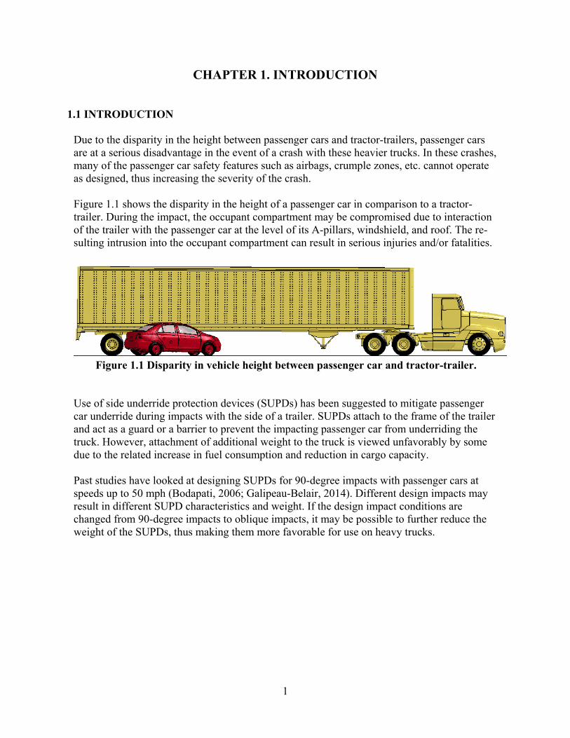
Due to the disparity in the height between passenger cars and tractor-trailers, passenger cars are at a serious disadvantage in the event of a crash with these heavier trucks. In these crashes, many of the passenger car safety features such as airbags, crumple zones, etc. cannot operate as designed, thus increasing the severity of the crash.
Figure 1.1 shows the disparity in the height of a passenger car in comparison to a tractor-trailer. During the impact, the occupant compartment may be compromised due to interaction of the trailer with the passenger car at the level of its A-pillars, windshield, and roof. The re-sulting intrusion into the occupant compartment can result in serious injuries and/or fatalities.
Figure 1.1 Disparity in vehicle height between passenger car and tractor-trailer.
Use of side underride protection devices (SUPDs) has been suggested to mitigate passenger car underride during impacts with the side of a trailer. SUPDs attach to the frame of the trailer and act as a guard or a barrier to prevent the impacting passenger car from underriding the truck. However, attachment of additional weight to the truck is viewed unfavorably by some due to the related increase in fuel consumption and reduction in cargo capacity.
Past studies have looked at designing SUPDs for 90-degree impacts with passenger cars at speeds up to 50 mph (Bodapati, 2006; Galipeau-Belair, 2014). Different design impacts may result in different SUPD characteristics and weight. If the design impact conditions are changed from 90-degree impacts to oblique impacts, it may be possible to further reduce the weight of the SUPDs, thus making them more favorable for use on heavy trucks.

2
1.2 BACKGROUND Blower and Woodrooffe (2013) conducted a heavy-vehicle crash data collection study in which they also analyzed side underride in fatal truck crashes. They analyzed a total of 411 valid colli-sions between a light vehicle and the front or side of a truck. The data was obtained from the Federal Motor Carrier Safety Administration and NHTSA’s large-truck crash causation study (LTCCS), whose cases are based on a sample of fatal and serious injury truck crashes. Out of these 411 cases, there were a total of 165 collisions recorded between a light vehicle and the side of a truck. It was observed that some portion of the light vehicle went under the truck in about 54 percent of the crashes, and that some level of passenger compartment intrusion (PCI) was rec-orded for about 49 percent of the light vehicles involved in the collisions.
Blower and Woodrooffe noted that underride in side impact crashes represents a more complex problem than rear underride. This is primarily due to the different crash modes associated with side impacts, which include perpendicular impacts on the truck side at intersections, shallow approach angles from opposite direction vehicle with a high closing speed, and shallow approach angles from same direction (e.g., vehicle drifting into the side of the truck, or truck changes lanes into the other vehicle). This study concluded that “with respect to side im-pacts, some crash geometries such as same direction sideswipes may be mitigated by side un-derride guards if closing speeds are low enough to be managed by practical structures.”
Galipeau-Belair, Ghantae, Critchley, Ramachandra, and El-Gindy (2014) proposed designs for side underride protection devices (SUPD) for attachment to tractor-trailers and straight trucks. The objective was to reduce the geometric incompatibility between small passenger vehicles and larger trucks, and to minimize occupant risk and PCI. The study included topology and multi-objective optimization design processes and used finite element impact simulations using the LS-DYNA code (Hallquist, 2016) to assist with the development and evaluation of the SUPD designs. The SUPD design for attachment to a tractor-trailer consisted of a thrie-beam rail design supported by tubular steel braces connected to the I-beams of the truck floor as de-picted in Figure 1.2. ASTM A653/A653M structural quality grade 80 steel was used for all of the parts of the SUPD. The width of the brackets is that of the structural I-beams to which they attach. The final design included 7 brackets spaced out evenly across the device. The two end brackets had a larger thickness compared to the other brackets. The width of the brackets matched the width of the trailer floor beams to which they were attached. The SUPD had a ground clearance of 15.7 in. The total mass of the SUPD system on both sides of the trailer was 853 lbs.
Figure 1.2 Final SUPD design for attachment to tractor-trailer (Galipeau-Belair, Ghantae,
Critchley, Ramachandra, & El-Gindy, 2014).
3
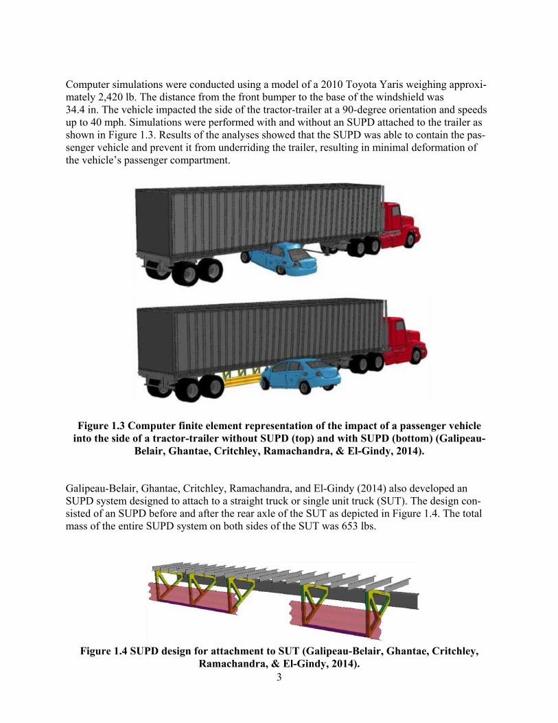
Computer simulations were conducted using a model of a 2010 Toyota Yaris weighing approxi-mately 2,420 lb. The distance from the front bumper to the base of the windshield was 34.4 in. The vehicle impacted the side of the tractor-trailer at a 90-degree orientation and speeds up to 40 mph. Simulations were performed with and without an SUPD attached to the trailer as shown in Figure 1.3. Results of the analyses showed that the SUPD was able to contain the pas-senger vehicle and prevent it from underriding the trailer, resulting in minimal deformation of the vehicle’s passenger compartment.
Figure 1.3 Computer finite element representation of the impact of a passenger vehicle into the side of a tractor-trailer without SUPD (top) and with SUPD (bottom) (Galipeau-
Belair, Ghantae, Critchley, Ramachandra, & El-Gindy, 2014). Galipeau-Belair, Ghantae, Critchley, Ramachandra, and El-Gindy (2014) also developed an SUPD system designed to attach to a straight truck or single unit truck (SUT). The design con-sisted of an SUPD before and after the rear axle of the SUT as depicted in Figure 1.4. The total mass of the entire SUPD system on both sides of the SUT was 653 lbs.
Figure 1.4 SUPD design for attachment to SUT (Galipeau-Belair, Ghantae, Critchley,
Ramachandra, & El-Gindy, 2014).

4
Computer simulations were conducted with a model of a Toyota Yaris to replicate a passenger vehicle impacting the side of the SUT at a 90-degree orientation and speeds up to 40 mph. Simulations were performed with and without an SUPD attached to the SUT as shown in Figure 1.5. Results of the analyses showed that some intrusion of the A-pillar occurred before the ve-hicle came to a complete stop.
Figure 1.5 Finite element impact of a passenger vehicle into the side of an SUT without SUPD (top) and with SUPD (bottom) (Galipeau-Belair, Ghantae, Critchley, Ramachan-
dra, & El-Gindy, 2014). 1.3 OBJECTIVES OF RESEARCH
The objective of this research study was to evaluate the design requirements and safety perfor-mance of SUPDs) subject to oblique impacts with passenger cars using finite element impact simulations. The SUPDs were designed for attachment to a tractor-trailer with the goal of re-ducing passenger car underride, occupant compartment intrusion, and injury severity. The goal was to minimize weight while safely accommodating oblique passenger vehicle impacts into the side of the trailer. The required weight of the SUPD is a function of the design impact con-ditions. Results of this simulation study provide relationships between SUPD weight, impact conditions, and lateral loading.
1.4 TECHNICAL PLAN
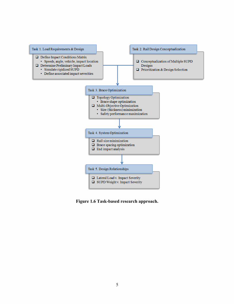
The flow chart presented in Figure 1.6 provides an overview of the research approach executed to accommodate the performance requirements and objectives outlined above. Details and re-sults of these tasks are presented in the following chapters of this report.
5
Figure 1.6 Task-based research approach.

6
CHAPTER 2. LOAD REQUIREMENTS & DESIGN CONSTRAINTS
2.1 DEFINE IMPACT CONDITIONS This section defines the impact conditions used for design and evaluation of the SUPD concepts under this project. The impact conditions include consideration of vehicle type, impact speed, impact angle, and impact location on the SUPD. The SUPDs developed under this project were designed for attachment to a tractor-trailer. SUPD designs for attachment to a single unit truck were not explicitly considered.
2.1.1 Passenger Vehicle Model
Finite element impact simulations were used to design and evaluate the performance of various SUPD concepts. The development of detailed finite element vehicle models is a substantial ef-fort beyond the scope of this project. Consequently, it was necessary to select a passenger car for which an appropriate finite element model was available. Available finite element passenger vehicle models include the 2001 Ford Taurus, 2012 Toyota Camry, and 2010 Toyota Yaris. The researchers reviewed key characteristics of these vehicles including front profile, bumper height, and weight. The bumper height is similar for all three vehicles. Therefore, other dimensions and factors were used as the basis vehicle model comparison and selection.
The curb weight for the Ford Taurus (3,331 lb) and Toyota Camry (3,215 lb) are similar, while the curb weight for the Toyota Yaris (2,309 lb) is significantly less. Both the Ford Taurus and Toyota Camry are grouped in the same NHTSA vehicle classification as medium passenger cars, while the Toyota Yaris is considered a light passenger car. The heavier class of passenger cars is considered more critical from an SUPD design standpoint because a heavier vehicle will impart more load on the device for a prescribed set of impact conditions.
Further comparison was conducted between the Toyota Camry and Ford Taurus models to make the final design vehicle selection. The distance from the front bumper to the base of the wind-shield is shorter for the Toyota Camry (45 inches) than the Ford Taurus (49 inches), which makes the Toyota Camry a more critical design vehicle in terms of underride propensity. In addi-tion, the finite element model of the Toyota Camry is a more recent model year vehicle, incorpo-rates more detail, and has a much finer finite element mesh (approximately 2 million elements). These enhancements enable the Toyota Camry model to provide more accurate deformation, loading, and impact response compared to the Ford Taurus model.
Based on this review, the Toyota Camry was selected as the design vehicle model for evaluation of the SUPD designs. This vehicle model, which was developed by researchers at George Mason University under a contract with the FHWA (Center for Collision Safety and Analysis 2016), is believed to represent a practical worst case for design and evaluation of the SUPDs while also providing the desired level of modeling detail. The model has an engine block height of 34.3 in.

7
2.1.2 Support Vehicle: Tractor-Van-Trailer Model and SUPD Design Space Similar to the design passenger vehicle, it was also necessary to select a design support vehicle with an existing finite element model. Evaluation of the SUPD attached to a trailer helps ensure acceptable impact performance by properly accounting for the mass, compliance, and stiffness of the tractor-trailer. The researchers used a finite element model of a tractor-van-trailer that was originally developed by National Crash Analysis Center (NCAC) and subsequently improved by Battelle under FHWA sponsorship. The tractor-van trailer that was modeled is considered repre-sentative of a large segment of the fleet. This model has subsequently been revised and im-proved by TTI researchers over the course of various research projects to enhance accuracy and robustness. The total weight of the ballasted tractor-van-trailer is 80,000 lb. The length of the trailer is 48 ft. This model of a tractor and dry van trailer is considered representative of a large segment of the fleet.
The design space for the SUPD system was 20 ft long as indicated by variable “L” in Figure 2.1. This length spanned a distance from aft of the landing gear to the front of the moveable rear bo-gie tandem in its most forward position. This range was selected to avoid interfering with access to the landing gear and functioning of the moveable rear bogie tandem.
The height of the SUPD system was selected with consideration of trailer ground clearance and interaction with impacting passenger vehicles. Federal Motor Vehicle Safety Standard (FMVSS) 581 has a bumper test zone of 16 to 20 inches. Although this standard involves a low-speed bumper test, it is reasonable to assume that interacting with the vehicle in this zone will provide good interaction between the vehicle bumper structure and SUPD. A distance of 18 inches from the ground to the bottom of the SUPD system was selected. This represents the middle of the Part 581 bumper standard test zone. The resulting design space for the SUPD is shown in Figure 2.1.
Figure 2.1 Design space for the SUPD system. It was also decided to align the traffic face of the SUPD with the outer edge of the trailer. When an aerodynamic side skirt is used, the SUPD would be directly behind the thin skirt material. Any additional offset of the SUPD provides free penetration distance of the vehicle prior to ve-hicle engagement. This is a disadvantage when designing an SUPD to redirect an impacting

8
vehicle with little or no occupant compartment intrusion because it may lead to a system that is stronger, stiffer, and heavier than would otherwise be required.
2.1.3 Impact Conditions
The ability to define impact conditions for design of SUPDs is limited by available crash data. The selection of design impact conditions for oblique impacts requires determination of both impact speed and impact angle. Different design impact conditions can result in different SUPD designs with different features and weight.
For purposes of this project, three different sets of impact conditions were defined in consulta-tion with NHTSA personnel. These three sets of design impact conditions were defined by one impact speed in combination with three different impact angles. The selected impact speed is 50 mph, and the selected impact angles are 15, 22.5, and 30 degrees.
During an oblique impact with an SUPD, the objective is to contain and redirect the impacting vehicle. The redirected vehicle has an exit velocity and, thus, not all of the energy of the vehicle must be dissipated by the SUPD. The lateral energy that must be managed by the SUPD is re-ferred to as the impact severity. Impact severity is defined as the lateral energy of the vehicle during an oblique impact with the SUPD and is a function of vehicle weight, speed, and angle as defined below:
Impact Severity (I.S.) = ½ M [V Sin(θ)]2
where M = vehicle mass, V = impact speed, and θ = impact angle. The three speed and angle combinations selected for this project define three impact severities as depicted in Figure 2.2. The design process considered impacts near mid-span and at the ends of the SUPD de-vice.
Figure 2.2 Impact severity from proposed impact conditions

9
2.2 DETERMINE IMPACT LOADS 2.2.1 Rigidized SUPD
The objective of this task was to determine the load requirements for designing the SUPD brac-es. A full-scale simulation was performed with the Toyota Camry impacting a rigidized longitu-dinal member that had a 4-inch wide impact face and was located 18 inches above the ground level. A 50-mph impact speed and 30 degree impact angle were used for this simulation. These impact conditions represent the maximum impact severity defined under the project.
The results of the simulation (see Figure 2.1) were used to evaluate the acceptability of a 4-inch wide contact interface and the 18-inch vertical ground clearance of the SUPD longitudinal rail member. The simulation was also used to determine the maximum loads resulting from a vehicle impact on a narrow longitudinal member. The vehicle was successfully contained and redirected by the 4-inch wide contact surface. The vehicle did not show potential for underriding the rail member, which indicated that the 18-inch ground clearance of the rail was acceptable.
2.2.2 Deformable SUPD with Springs
An additional impact simulation was performed to estimate the distribution of load in the braces along the length of the SUPD. This was accomplished by replacing the rigidized beam with a deformable 4-inch x 4-inch x 1/4-inch tubular steel beam. The tubular steel beam was supported by lateral and vertical springs at discrete locations representing an assumed brace spacing. A sliding constraint was modeled at the free ends of the beam to compensate for the lack of tor-sional stiffness in the springs. The model concept is shown in Figure 2.3.
Figure 2.3 Simulation with rigid longitudinal member.
Based on testing experience with roadside barrier systems and the relative stiffness considered necessary for successful containment and redirection of vehicles by the SUPD, the research team selected an initial brace spacing of 5 ft. This provides a total of 5 braces along the 20-ft design length of the SUPD. The lateral and vertical load distributions calculated from the simulation with the highest impact severity (i.e., 50 mph impact at 30 degrees) are shown in Figure 2.4.

10
The researchers performed similar impact simulations for the 22.5-degree and 15-degree impact angles to determine the load distributions for the other impact severities selected for the SUPD design. The maximum lateral brace design loads obtained for each design impact severity are shown in Table 2.1. These loads occur at the first brace downstream of the impact point (i.e., lo-cation C shown in Figure 2.5). These loads were used in design and optimization of the SUPD braces as described in Chapter 4.
braces. Locations A, B, C, D, and E are the brace locations as shown in Figure 2.4.
Lateral and Vertical Loads in Spring Elements at Brace Locations Figure 2.4 Lateral and vertical loads calculated at the locations of the surrogate spring
Table 2.1 Brace lateral design impact loads for 50-mph impact speed and impact angles of
30, 22.5 and 15 degrees.
Impact Angle (degrees)
Peak Lateral Load kips
30 40.5 22.5 32.6 15 22.9

11
Figure 2.5 FE model with deformable tube and spring elements as SUPB braces.
12
CHAPTER 3. SUPD DESIGN CONCEPTS
Several different SUPD rail concepts were explored, and the two best candidates were selected for further detailed design and development. Each of the concepts was reviewed with considera-tion of strength, weight, cost, and attachment requirements to the trailer undercarriage. Three different shapes were identified as possible rail elements: a closed tubular shape, a bent plate hatshape, and a standard W-beam guardrail shape. Two different materials were selected for in-vestigation: steel and aluminum. The objective was to find combinations of shape and material that provided a high bending strength-to-weight ratio and were practical to fabricate at reasona-ble cost. It was desired to achieve a rail system that was strong enough to contain and redirect a passenger car without occupant compartment intrusion yet light enough for practical implemen-tation. The following sections describe the selection process used to select preliminary SUPD rail concepts with input from NHTSA and FHWA.
3.1 SUPD RAIL SHAPE
3.1.1 HSS Tube
Tubular members were identified as a leading candidate for both steel and aluminum rail mem-bers. Closed tubular members have a large flexural strength and stiffness combined with a high torsional resistance. Another benefit of using a rectangular tube as the longitudinal rail is its wide availability. These shapes are easily attained in a variety of sizes and thicknesses, and they are often used in the roadside safety industry as guardrail or bridge rail members. Furthermore, the closed section offers the opportunity for a simple welded connection of the rail to the braces without the addition of special connection plates or brackets.
Researchers initially identified an HSS 4” x 4” x 3/16” steel tube as a starting point for evalua-tion and optimization through preliminary impact simulations. These simulations indicated that an HSS 4” x 4” x 3/16” tube exhibited good impact performance and, therefore, this shape was selected for further refinement in the system optimization analyses presented in Chapter 5.
3.1.2 Hat Shape
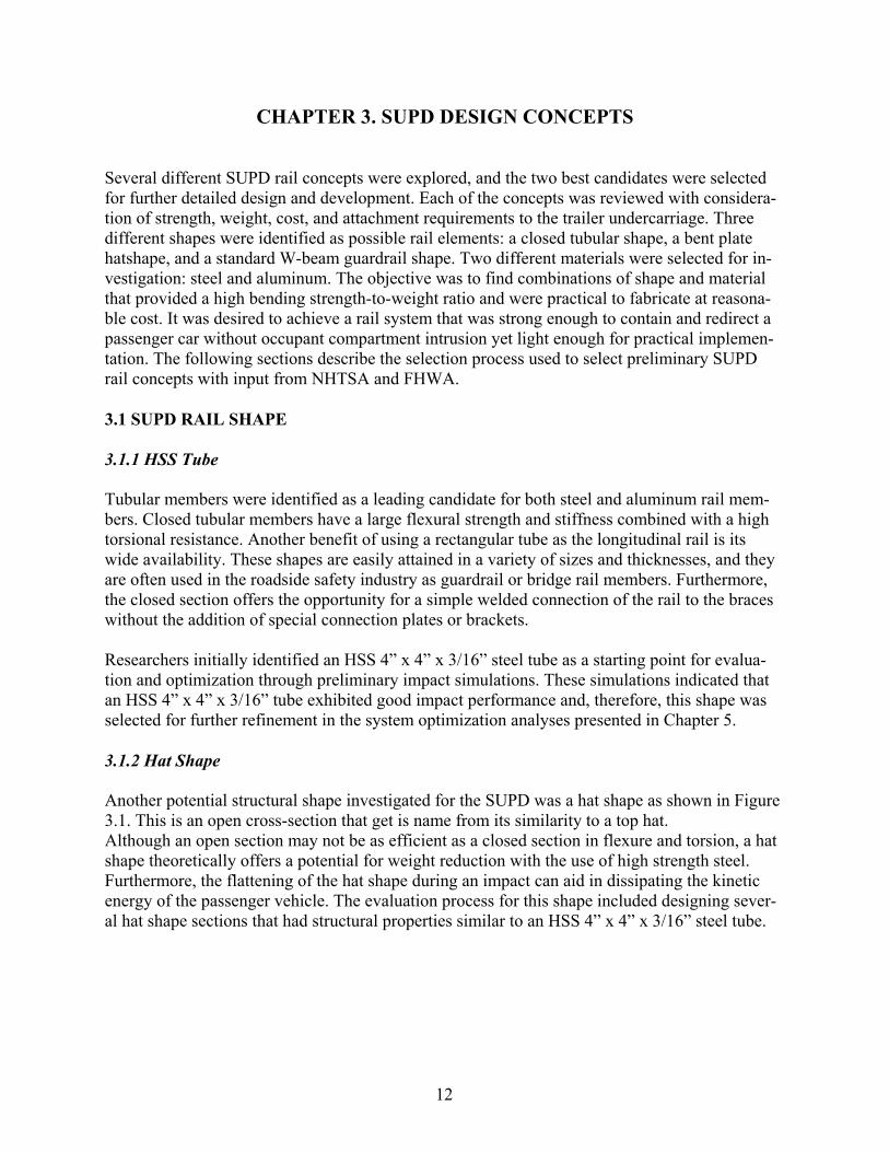
Another potential structural shape investigated for the SUPD was a hat shape as shown in Figure 3.1. This is an open cross-section that get is name from its similarity to a top hat. Although an open section may not be as efficient as a closed section in flexure and torsion, a hat shape theoretically offers a potential for weight reduction with the use of high strength steel. Furthermore, the flattening of the hat shape during an impact can aid in dissipating the kinetic energy of the passenger vehicle. The evaluation process for this shape included designing sever-al hat shape sections that had structural properties similar to an HSS 4” x 4” x 3/16” steel tube.

13
Figure 3.1 Open hat-shape cross section Unlike the tubular members, the open hat shape section has two wings that extend outward from the centroid of the shape. This open shape design caused buckling and torsional deformation modes to arise during the preliminary impact simulations. Furthermore, the connection to the braces is more complicated for this open cross section. A strap or plate is needed across the back of the rail to enable connection to the braces. Depending on the span length between brac-es, additional intermediate stiffener straps were required to help the open hat rail retain its shape during impact and more effectively use its flexural strength when redirecting a vehicle. This added fabrication cost and complexity as well as additional weight to the rail. Furthermore, the high strength material (e.g., 100 ksi yield) required to make this an efficient design from a strength standpoint was significantly more expensive than standard steel material grades used for the closed tubular sections.
In an effort to overcome some of the issues and limitations of the hat section, an open tubular section was considered as shown in Figure 3.2. This section provides a larger torsional resistance and stiffness for the same amount of steel compared to the open hat shape. However, discussions with steel fabricators raised concerns regarding the constructability of this rail shape. The inward facing “wings” prevented steel fabricators from being able to readily bend this shape. Thus, this shape was also abandoned for this project.
Figure 3.2 Open tubular cross section

14
3.1.3 W-Beam A corrugated W-beam guardrail section was also selected for evaluation as an open rail element for the SUPD (see Figure 3.3). This is a common cross section used in roadside guardrail sys-tems. The shape is nominally 12 inches tall, 3 ¼ inches wide, and 0.105 inches (12 gauge) thick, and has a weight of about 6.7 lb/ft. It was theorized that the increased height of this rail could engage more of the vehicle and potentially improve the interaction between the vehicle and the SUPD.
Because of the similarities between the desired vehicle redirection performance of the SUPD and a roadside guardrail installation, the W-beam rail element was evaluated through prelimi-nary impact simulations. In a roadside guardrail impact, the W-beam guardrail redirects the ve-hicle by developing tension in the W-beam rail member and absorbing vehicle energy through post deflection and flattening of the W-beam corrugations. To avoid the need for strong, heavy end braces, tension members were added that connected the ends of the W-beam rail to the trail-er to aid in developing tension in the rail member. However, even with the addition of the ten-sion members, the open W-beam section had large deflections and vehicle pocketing rather than smooth redirection. Significantly reduced brace spacing would be required to improve the im-pact performance of the W-beam rail. Since this would negate any potential weight savings as-sociated with the rail element, this design concept was abandoned for this project.
Figure 3.3 W-beam cross section
15
3.2 SUPD MATERIAL 3.2.1 Steel
Steel is often used in roadside safety barriers because of its high strength and stiffness. Fur-thermore, it is a relatively inexpensive and widely available construction material. However, steel is a heavy material, which was a concern for this research project.
HSS rectangular tubing is readily available in ASTM A500 Grade B steel, which has a yield strength of 46 ksi. Therefore, this specification was used for the tubular steel rail concept.
Higher strength steels are available and offer promise for reducing SUPD weight due to their greater strength to weight ratio. As an example, ASTM A514 steel plate has a yield strength of 100 ksi. The use of this high-strength steel specification was considered for the hat section rail concept as a possible means of reducing weight. The hat-shaped rail sections were sized to match the flexural strength of the closed tubular rail section.
It was confirmed that the hat sections could be fabricated using high-strength steel. However, the fabricated cost of this material was approximately 13 times more expensive than standard steel grades such as ASTM A500, and the weight savings was not as significant as initially en-visioned. During impact, the open hat section lost its shape due to flexural and torsional defor-mation. The loss of shape reduced the strength of the section and led to larger than desired rail deflections. Efforts to mitigate this behavior included the addition of intermediate stiffener plates and thicker rail cross section. While these design strategies were effective in improving impact performance, they increased the weight of the system. The addition of connection plates at the brace locations further incrementally increased the weight. Consequently, the research team abandoned the use of the high-strength steel, and focused on a closed tubular rail section fabricated from the readily available and less expensive ASTM A500 Grade B steel.
3.2.2 Aluminum
Aluminum was considered an ideal candidate for designing a lightweight SUPD due to its high strength-to-weight ratio. The density of aluminum (170 lb/ft3) is one third the density of mild steel 495 lb/ft3). Despite the weight benefits, there are drawbacks associated with using an alu-minum SUPD system. When two dissimilar metals are in contact, such as the connection of an aluminum SUPD to a steel trailer frame, precautions need to be taken to prevent accelerated galvanic corrosion from occurring. However, such issues are not uncommon and can be ad-dressed through various means such as application of corrosion-inhibiting coatings and use of plastic washers, gaskets, and sleeves under the head of bolts and nuts at the connection points between the dissimilar metals.
An aluminum SUPD system can also be more expensive in terms of both material and fabrica-tion compared to a tubular steel system. In this instance, the fabricated cost of the aluminum rail is about 1.5 times that of a steel rail of comparable strength. However, the considerable weight savings can make an aluminum system cost effective from a life-cycle cost standpoint.

16
3.3 SUMMARY Several concepts were considered for the design of SUPDs for oblique impacts. After preliminary investigations and consideration of factors such as strength, weight, cost, and availability, it was decided to demonstrate design feasibility with rail shapes and ma-terials that are readily available in a variety of sizes and functionally efficient in terms of weight-to-strength ratio. More specifically, the rail concepts that were selected for fur-ther development and analysis in the SUPD system were closed tubular sections fabri-cated from ASTM A500 Grade B mild steel and 6061-T6 aluminum.

17
CHAPTER 4. BRACE OPTIMIZATION
The design optimization approach followed in this study consists of three key processes, a to-pology optimization process, a concept extraction process, and a multi-objective optimization process. Figure 4.1 shows these three key processes along with the input for the topology op-timization process.
Design Space and Loading Requirements
Topology Optimization
Concept Extraction
Multi-objective Optimization
Optimizied SUPD Design
Figure 4.1 Optimization approach followed in this pro-ject
The SUPD has two distinct sub-assemblies: the outside longitudinal rail that acts as the interface with an impacting passenger vehicle, and the inside support structure that transfers load between the outside rail interface and the trailer to which the SUPD is attached. The outside rail is ex-pected to have uniform cross section along its length since the vehicle can impact anywhere along its length. However, the inside support structure does not have to be continuous along the length of the rail member and is more efficiently prescribed by discrete components (i.e., brac-es) spaced as needed to accommodate impact loads and meet safety performance requirements. These support components are generally connected to the outside interface at one end and to mounting positions on the trailer cross members on the other end.
Topology optimization was used to optimize the shape of the inside support system to efficiently transfer load to the trailer. Multi-objective optimization was subsequently used to optimize the size and weight of both the optimized brace shape and the longitudinal rail member.

18
4.1 TOPOLOGY OPTIMIZATION The research team used topology optimization to define an initial brace configuration for the SUPD braces for the prescribed impact forces defined in Chapter 2. The initial design space se-lected for a brace is a three dimensional volume beneath the trailer cross members extending down to a height of 18-inches above the ground. This space is constrained laterally by the lon-gitudinal edge of the trailer on the outside and the longitudinal trailer centerline on the inside. Finally, this volume is bounded along the length of the trailer based on the number of trailer cross members being considered for the brace mounting. In this project, two different mount-ing cases were considered: (1) mounting to a single trailer cross member, and (2) mounting to two adjacent trailer cross members. It was theorized that a brace attached to two cross mem-bers could provide better internal stability against longitudinal sway of the SUPD and, there-fore, be lighter in weight. Figure 4.2 shows the design space for the topology optimization of the braces for the case of mounting to two trailer cross members.
Figure 4.2 A solid block representing design space underneath two trailer cross members.
The research team used boundary conditions to represent the attachment of the design space to the trailer cross members and the longitudinal rail element. The use of boundary conditions sig-nificantly reduces the complexity and the computational time associated with the topology op-timization. The design space volume and related boundary conditions for the two cross member attachment case is shown in Figure 4.3. Similarly, the design space volume and boundary condi-tions for a single cross member attachment case is shown in Figure 4.4.

19
Figure 4.3 Design space for two braces attachment concept
Figure 4.4 Design space under one trailer cross member
The highest impact loads determined from the spring brace system model described in Chapter 2 were applied to the brace design space. The loads for the highest impact severity:
• Lateral load = 41.7 kips • Longitudinal load = 2.7 kips • Vertical load = 5.8 kips
The loads were applied to the lower front edge of the brace design space volume over a 4 inch x 4 inch area that represented the contact area of the SUPD rail.

20
Once the setup for the brace topology analysis was completed, the topology optimization was performed using LS-TaSC (Roux et al., 2016). The topology optimization iteratively and sys-tematically removes unneeded mass from the design space based on state of stress in the ele-ments. The objective is to obtain optimal distribution and utilization of mass subject to the pre-scribed loads. The resulting mass distribution has to be contiguous to be a viable design. In other words, there are no isolated or separate material parts.
Figure 4.5 Optimized brace layout showing recommended material distribution for single
cross member mounting case The topologically optimized material layouts for the single cross member mounting and two- cross member mounting cases are shown in Figure 4.5 and Figure 4.6, respectively. As can be noted from these figures, significant material was removed from the initial design space blocks. The resulting mass distribution represents the best material utilization for resisting the applied loads. The topology optimization essentially defines an optimal shape or load path for transmitting forces from the SUPD rail to the supporting trailer structure. The fringes shown in these figures are a gradation of material utilization. With reference to Figure 4.5, the highest range of the fringe scale (1.0) represents 100 percent utilization of the element. Mass elements with less than 100 percent utilization indicate an opportunity for further optimization. Collec-tively, the cross-sectional area along with the percent utilization of those elements indicates the optimal material required to resist the applied loads.
21
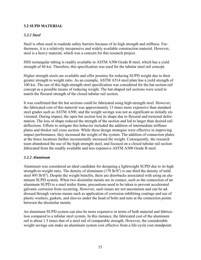
Figure 4.6 Optimized brace layout showing recommended material distribution for two
cross member mounting case
The two cases of topology optimization presented above suggest two key points. First, the shape of the material distribution for the two cross member mounting case is very similar to the shape of the material distribution for the single cross member mounting case. Thus, there is no distinct benefit derived from the two cross member mounting case. The dual members shown in Figure 4.6 are essentially parallel distinct members and do not provide an alternative shape compared to the single cross member mounting case. Thus, rather than use two parallel members, it is simpler and more direct to use a single brace member that connects to a single trailer cross member.
Second, the results indicate that the front brace member can be slanted to make it carry load in tension. This reduces the applied bending moment resulting from the impact loads on the rail section, which can help reduce the required size and weight of the front brace member.
The research team extracted brace design concepts from the topology optimization results. The initial engineering concept was a brace system comprised of channel sections. The percent ma-terial utilization for the smallest cross section for each brace member was used to provide the initial engineered design.
The channel brace concept with vertically oriented front member is shown in Figure 4.7. The channel brace concept with diagonally oriented front member is shown in Figure 4.8. Both shapes were considered in the initial optimization analyses. The brace design with the diago-nally oriented from member was found to be more efficient in accommodating the impact loads because its orientation enabled it to act more as a tension member rather than a purely flexural member in bending. Additionally, the diagonal or slanted orientation of the front member further reduced potential for interaction with an impacting vehicle, which could

22
compromise the brace strength and reduce the redirection efficiency of the SUPD system. The shape, size, and thickness of the individual members of the brace system were further analyzed and refined through the multi-objective optimization process described below.
Figure 4.7 Brace design with vertically oriented front member
Figure 4.8 Brace design with diagonally oriented front member
4.2 MULTI-OBJECTIVE OPTIMIZATION The overall brace geometry was derived from the previously performed topology optimization. Data from the topology optimization was also used to initially size the channel sections that served as the braces structural components. The brace geometry consisted of a front vertical member and a rear diagonal member that extend down from the trailer floor, and a short hori-zontal member that extends from the intersection of the front and rear members to the main longitudinal rail of the SUPD. The horizontal member offsets the rail element from the brace components, which reduces the potential for vehicle contact with the braces.

23
The LS-OPT multi-objective optimization program (Stander, Roux, Basudhar, Eggleston, Goel, & Craig, 2015) was used to optimize the thickness of the brace members subject to an imposed deflection constraint. A deflection constraint of 4 inches was enforced on the maxi-mum lateral deflection of the SUPD system. This value was initially selected to help mini-mize contact between the trailer floor and vehicle A-pillar during vehicle redirection and, thereby, minimize potential for occupant compartment intrusion.
The optimization iterations applied the full force-time history for the lateral, vertical, and longi-tudinal impact loads for each brace as defined in Chapter 2. LS-DYNA is the solver that per-forms the finite element analysis for a given design iteration (Hallquist, 2016). LS-OPT calls LS-DYNA to build response surfaces of the total mass and the maximum rail deflection so it can perform optimization using these surfaces.
4.2.1 Steel Channel Section brace Design
A total of 5 braces were modeled along the length of the 20-ft rail member. For purposes of the multi-objective optimization, the rail member was modeled as a 4-inch x 4-inch x 3/16-inch tubular steel section. The setup of this optimization case is shown in Figure 4.9.
The channels were initially modeled with 1 ½-inch legs and 5-inch deep web using a mild steel with a yield stress of approximately 50 ksi. The starting thickness of the channel members was 0.375 inches. The initial optimization analysis resulted in a reduction in channel thickness from 0.375 inches to 0.205 inches, which equated to a weight of 30 lb/brace.
The deformed shape of the braces is shown in Figure 4.10. It was noted that buckling was the limiting factor that controlled the thickness of the channel sections. Thus, the material strength was not being fully used. Various strategies for stiffening the channel sections to increase the buckling load were considered, including gusset plates and stiffener plates. It was decided to add an interior stiffener plate between the channel flanges at the location where buckling occurred in the brace during the initial optimization analysis. This design detail is shown in Figure 4.11.
Figure 4.9 LS-OPT optimization setup with load histories applied at each brace

24
Figure 4.10 Localized buckling at the intersecting joint of the three channel sections of the brace
Figure 4.11 Brace design with stiffening plate A subsequent optimization analysis with the stiffened braces resulted in a further reduction in material thickness to 0.166 inches, which resulted in a weight of 24 lb/brace. The addition of the stiffener plate delayed the buckling of the brace member to a higher load state but did not eliminate it. The fact that the size and thickness of the channel sections were being controlled by buckling and twisting modes of deformation rather than bending indicated that the material utilization and, hence weight of the braces, was not being fully optimized. The use of open channel sections for the brace components was, therefore, abandoned in favor of closed, tubu-lar-shaped members that possess improved and more efficient torsional and buckling capaci-ty.

25
4.2.2 Tubular Steel Brace Design Engineering analysis was performed to estimate an initial size for the tubular brace members based on the last design iteration of the channel section. Since closed tubular cross sections have higher buckling forces than their mass equivalent open sections, a better mass utilization is ex-pected from braces comprised of tubular members. Thus, the resulting weight of the braces will be reduced.
A 3-inch x 3-inch tubular steel section with the properties of ASTM A500 Grade B steel was initially selected for the revised brace design. LS-OPT was again used to optimize the material thickness of the support braces comprised of the tubular steel components subject to the same lateral, vertical, and longitudinal design impact load distributions. The design was also con-strained to have the same maximum lateral deflection limit of 4 inches. Additionally, a mini-mum material thickness of 14 gauge (0.075 inches) was selected based on fabrication practicali-ty.
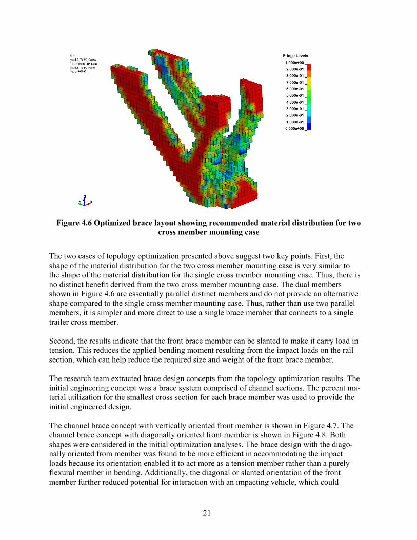
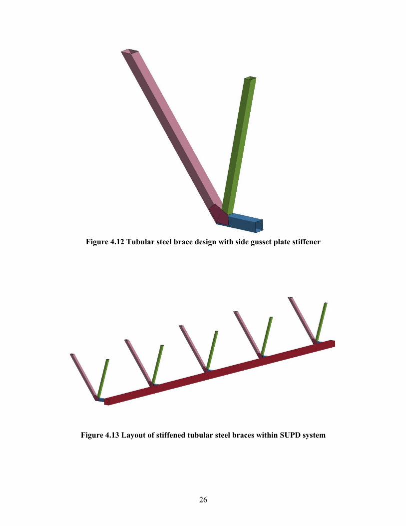
The tubular steel section was found to be much more efficient than the open channel section. However, buckling was still the controlling mode of deformation. A 12-gauge gusset plate was added at the junction of the diagonal and horizontal members to increase effective strength and determine if further reduction in weight can be achieved. Figure 4.12 shows the tubular steel brace design with the gusset plate at the joint of the three brace components. The addition of the gusset plate changed the mode of failure from buckling of the rear brace member at or near the joint to flexure of the rear brace member. This indicated that the stiffened tubular steel brace de-sign had efficient mass utilization. An optimal steel brace design was then achieved through it-eration of the size and thickness of the brace members. The layout of the five braces with the rail is shown in Figure 4.13.
The optimization analysis of the stiffened brace design indicated that the minimum specified material thickness for the 3-inch x 3-inch tubular steel sections was acceptable. Consequently, the size of the tubular section comprising the braces was decreased to 2 inches x 2 inches. Once again, the optimization indicated that the minimum specified 14-gauge material thickness would satisfy the 100 mm deflection constraint.
The size of the front diagonal member, which acts more as a tension member, was further re-duced to 1 ½ inches x 1 ½ inches. The optimization indicated the minimum 14-gauge thickness for the front 1 ½ inch x 1 ½ inch diagonal member and a 12-gauge (0.105 inch) thickness for the rear 2 inch x 2 inch diagonal member.
26
Figure 4.12 Tubular steel brace design with side gusset plate stiffener
Figure 4.13 Layout of stiffened tubular steel braces within SUPD system

27
The resulting final optimized tubular steel brace design was as follows.
• 2 inch x 2 inch x 12-gauge (0.105 inch) thick rear diagonal member, • 1 ½ inch x 1 ½ inch x 14-gauge thick front diagonal member, • 2 inch x 2 inch x 12-gauge (0.105 inch) front horizontal member, and • 12-gauge gusset plate
The resulting brace weight was 14.4 lb/brace. The total weight of 5 braces was, therefore, 72 lb.
4.2.3 Tubular Aluminum Brace Design
A similar process was used for the optimization of a tubular aluminum brace design. Aluminum 6061-T6 specifications were used for the material properties. The initial size of the three brace members was based on the member strength in the optimized tubular steel brace design. This re-sulted in brace members of similar size as the final tubular steel brace design but with increased thickness. The thickness of the aluminum members was then optimized using LS-OPT in an iter-ative manner similar to that followed for the tubular steel brace design.
This analysis resulted in optimized aluminum braces that met the specified deflection constraint that are considerably lighter than the steel system. The tubular aluminum brace weight is 8.4 lb/ft compared to 14.4 lb/ft for the tubular steel brace design, thus representing a significant weight savings.
The resulting final optimized tubular aluminum brace design is shown in Figure 4.14. The de-sign is comprised of the following parts and members
• 2 inch x 2 inch x 3/16-inch thick rear diagonal member • 1 ½ inch x 1 ½ inch x 1/8-inch thick front diagonal member • 2 inch x 2 inch x ¼-inch front horizontal member • ¼-inch gusset plate
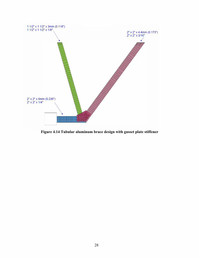
28
Figure 4.14 Tubular aluminum brace design with gusset plate stiffener

29
CHAPTER 5. SYSTEM OPTIMIZATION
5.1 SUPD SYSTEM DESCRIPTION The optimized SUPD brace designs were incorporated into a detailed finite element model of a tractor-van trailer vehicle. Impact simulations were performed to further design and optimize other components of the steel and aluminum SUPD systems. Below are discussed the compo-nents of the designed and evaluated SUPD concepts, which include metal braces (steel or alumi-num), close-shaped steel rail, steel tension rods, and brace stiffening connections (achieved with inclusion of wood blocks).
5.1.1 SUPD Design Space
The design space for the SUPD system consisted of 20 ft of length, spanning be-tween the landing gear and the rear bogie tandem. The SUPD system has a ground clearance of approximately 18 inches to the bottom of the rail. Figure 5.1 shows the SUPD design space for attachment to the tractor-van-trailer.
Figure 5.1 Design space for the SUPD system.
5.1.2 SUPD Braces Two brace designs were developed and optimized for the SUPD system. When integrated into the tractor-van trailer model, the brace components were rigidly attached to the lateral I-beams of the trailer floor. The number and spacing of the SUPD brace varies for each system and each im-pact severity level based on the results of an optimization process described later in this report. Figure 5.2 depicts the basic SUPD brace design after attachment to the tractor-van trailer model.
The steel brace design consists of the follow-ing components.
• 2-in x 2-in x 12 gauge rear slanted member that attaches to the trailer floor beams
• 1 ½-in x 1 ½-in x 14 gauge front slanted mem-ber that attaches to the trailer floor beams
• 2-in x 2-in x 12 gauge anterior horizontal member that con-nects to the rail and offsets the rail
Figure 5.2 SUPD braces design.

30
from the other brace members • 12 gauge gusset plate at the intersection of the three brace members
The aluminum brace design consists of the following components:
• 2-in x 2-in x 3/16-in posterior slanted member that attaches to the trailer floor beams, • 1 ½-in x 1 ½-in x 1/8-in anterior slanted member that attaches to the trailer floor beams,
and • 2-in x 2-in x ¼-in anterior horizontal member that connects to the rail and offsets the rail
from the other brace members, and • ¼-inch gusset plate at the intersection of the three brace members.
5.1.3 SUPD Rail The SUPD system includes a closed, tubu-lar rail component. The rail was rigidly connected to the horizontal member of the braces. Each end of the rail tapers inward under the trailer at a 45 degree angle to achieve a 9 inch setback. This end detail is designed to help mitigate vehicle snagging potential on the rail ends when the SUPD is impacted near the end. The size and thickness of the rail member was the result of an optimization process described later in this report. Figure 5.3 depicts the SUPD rail design.
Figure 5.3 SUPD rail design
.

31
5.1.4 SUPD Tension Rods
The SUPD system incorporates steel tension rods that connect the ends of the rail member to the trailer floor beams. The tension rods were added to provide longitudinal stability to the SUPD system. A vehicle impact imparts lateral, vertical, and longitudinal forces to the SUPD system.
Preliminary design simulations indicated that the longitudinal impact forces had a tendency to cause the SUPD system to shift and displace in the longitudinal direction. This compromised the strength of the braces and increased dynamic deflection of the SUPD system. Rather than sub-stantially increase the size and weight of the end braces or provide additional bracing between the braces, it was determined that this mode of deformation could be mitigated through the addi-tion of 3/8-inch diameter tension rods on each end of the rail. Figures 5.4 and 5.5 show the SUPD tension rods deployed for stability of the SUPD system.
Figure 5.4 SUPD tension rod locations. Figure 5.5 SUPD tension rod (zoomed image).
5.1.5 SUPD Brace Connection Stiffening
The SUPD system included stiffened connections at the attachment of the posterior diagonal brace member to the lateral trailer floor I-beams. This was achieved by bolting a 6-in long piece of 2x4 lumber (1.5-in x 3.5-in actual dressed dimension) to the floor I-beam just above the brace connection location. The inclusion of the wood blocks addressed localized deformation of floor I-beams that was identified during preliminary design simulations. The localized buckling of the floor beams permitted rotation of the braces and compromised the strength of the SUPD system. The wood blocks provide a simple, low cost solution to this problem. Figures 5.6 and 5.7 show the SUPD brace connection stiffening blocks incorporated into the SUPD system.

32
Figure 5.6 SUPD brace connection stiffening Locations.
Figure 5.7 SUPD brace connection stiffening (zoomed image).
5.2 SUPD SYSTEM OPTIMIZATION
Both the steel and aluminum SUPD systems were further optimized following a specific multi- objective optimization process illustrated in Figure 5.8. This iterative process consisted of four primary steps:
1. For a given impact severity, an initial number of braces and brace spacing is chosen. 2. Size and thickness of the closed, rectangular, tubular rail are optimized through iterative
selection and evaluation of available rails. The objective is to minimize the weight of the rail member subject to impact performance requirements (which are described in the next section).
3. Once the rail dimensions are optimized for the initial number of braces, the number of braces is minimized through additional impact simulations.
4. Finally, the brace spacing is optimized to accommodate impacts along the full length of the SUPD system. This process involves increasing the brace spacing in the middle of the SUPD and correspondingly decreasing the brace spacing near the ends of the system. Impacts near the end of the system are more critical than midspan impacts due to the lack of continuity of the rail member at the free ends. Thus, the brace spacing is de-creased to avoid the need to add additional braces near the ends, which would increase both the cost and weight of the SUPD system. The brace spacing was iteratively in-creased in the middle of the SUPD until the performance requirements were exceeded. Note that the brace spacing had to be varied in 1 ft increments to conform to the spacing of the trailer floor beams.
Steps 2 through 4 all involved iterative impact simulations of the SUPD system subject to the prescribed set of impact conditions (i.e., impact severity). at each step, the design element (e.g., rail, number of braces, or brace spacing) was iterated to further decrease weight or increase brace spacing in the middle of the SUPD system. The process was continued until performance re-quirements were exceeded.
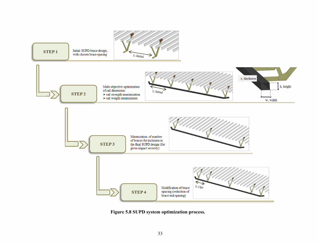
33
Figure 5.8 SUPD system optimization process.

34
As the brace spacing was modified in Step 4, the impact location for the passenger car was also modified to account for the change in stiffness in the middle of the SUPD system. The intent was to select a critical impact location for each bracing span length to maximize the dynamic de-flection of the SUPD system for the prescribed impact conditions. If acceptable impact perfor-mance is obtained at the critical impact location along the length of the SUPD, acceptable im-pact performance should result when the SUPD is impacted at other, less critical locations. Note that the impacts near the end of the system were separately evaluated. The results of these simulations are documented in Chapter 6 of this report.
This process was followed for each of the three impact severity levels for both the steel and aluminum SUPD systems. Details of the final recommended SUPD designs for each im-pact severity and material type are described in subsequent sections of this chapter.
5.3 SUPD IMPACT PERFORMANCE EVALUATION
Results of each simulation were analyzed to evaluate the impact performance of the various SUPD design variations. Several performance metrics were assessed, including the following:
Structural Adequacy: The SUPD system had to demonstrate ability to contain and redi-
rect the impacting vehicle under the prescribed impact conditions. SUPD Deflection and Deformation: Maximum dynamic deflection of the SUPD system
was obtained and reported. Although the extent of system damage and deformation was not a pass/fail criterion, it provided useful information regarding the performance limits of the sys-tem and whether or not additional optimization could be achieved.
Passenger Compartment Intrusion: Passenger compartment intrusion (PCI) was the prima-
ry acceptance criteria for the SUPD system evaluation. Deformation of or intrusion into the passenger compartment of a vehicle involved in a crash has been correlated with occupant injury. The probability and severity of injury can be related to the location and magnitude of the PCI. In regard to SUPD systems, the primary concern is vehicle underride of the trailer and any contact with and deformation of the A-pillar. Thus, the researchers established a performance criterion associated with A-pillar deformation and intrusion on the impact side of the vehicle. Slight deformation of the A-pillar was considered acceptable. Slight defor-mation was defined as exterior-only deformation of the A-pillar without resulting in any cor-responding passenger compartment deformation or intrusion. This scenario is depicted in Figure 5.9(a). Unacceptable deformation consisted of any inward buckling or deformation of the A-pillar that caused any degree of deformation or intrusion into the passenger compart-ment. An example of unacceptable A-pillar deformation is provided in Figure 5.9(b). Alt-hough this criterion may be viewed as somewhat conservative in nature, it was considered appropriate given that the evaluation was based solely on finite element simulation without any validation testing.

35
(a) Acceptable – Zero PCI (b) Unacceptable PCI
Figure 5.9 Passenger compartment intrusion safety performance evaluation criteria. An abbreviated example of the iterative design optimization process described in Section 5.2 is provided below.
Given: Steel SUPD system subject to impact at a speed of 50 mph and angle of 30 degrees.
Step 1. Choice of initial number and spacing of steel braces. The initial design configuration includes five (5) steel braces with four equal 5-ft spans (i.e., spacing of 5ft -5ft - 5ft - 5ft) as shown in Figure 5.10.
Figure 5.10 Side view of steel SUPD system with 5ft - 5ft - 5ft - 5ft spacing (50-mph and 30-deg. impact conditions).
Step 2. Optimization of rail dimensions. Rail dimensions (height, width, and thickness) are optimized through iterative selection of pro-gressively lighter (or heavier) tubular steel rail sections that are readily available. A 6.0-in (high) x 4.0-in (wide) x 1/8-in (thick) steel tubular rail with a weight of 8.16 lb/ft was initially selected for evaluation. The simulation results indicated that the Toyota Camry was contained and redirected by the SUPD. The vehicle interaction with the side of the trailer resulted in de-formation of the left A-pillar shown in Figure 5.11. This deformation resulted in intrusion of the passenger compartment and, therefore, was considered unacceptable.

36
Figure 5.11 Deformation of left A-pillar resulting from 50-mph and 30-degree impact into steel SUPD system with 5ft - 5ft - 5ft - 5ft brace spacing and 6.0-in × 4.0-in × 1/8-in rail.
The results indicated the need for a stronger rail member that would further limit the deformation of the SUPD system while limiting the increase in weight. A 3.5-in (high) x 3.5-in (wide) x 3/16-in (thick) steel tubular rail with a weight of 8.15 lb/ft was chosen. The Toyota Camry was contained and redirected. As shown in Figure 5.12, there was no contact between the trailer and vehicle A-pillar and, thus, no passenger compartment intrusion. The impact performance of this SUPD configuration was considered acceptable.
Figure 5.12 No contact with left A-pillar during 50-mph and 30-degree impact into steel SUPD system with 5ft - 5ft - 5ft - 5ft brace spacing and 3.5-in × 3.5-in × 3/16-in rail.
Step 3. Minimize number of braces. Following the optimization of the rail dimensions, the number of braces was minimized. For this specific example, which involves the highest impact severity, there was no further reduc-tion in the number of braces. When the number of braces was reduced from five (5) to four (4), the impact simulation indicated A-pillar deformation that resulted in PCI.

37
Step 4. Optimize brace spacing. An iterative process was followed to optimize the spacing of the five braces. The primary objec-tive was to determine the minimum end span that would still result in acceptable impact perfor-mance in the middle of the SUPD. As the brace spacing was modified, the critical impact loca-tion for the passenger car was also modified to account for the change in stiffness in the middle of the SUPD system. The first brace spacing pattern evaluated was 4 ft - 6ft - 6ft - 4ft as depicted in Figure 5.13.
Figure 5.13 Illustration of SUPD system with 4ft - 6ft - 6ft - 4ft brace spacing. The Toyota Camry was contained and redirected. During the impact, there was no interaction be-tween the A-pillar of the vehicle and the trailer and, thus, no A-pillar deformation as shown in Figure 5.14. Since there was no PCI, this SUPD configuration had acceptable impact perfor-mance.
Figure 5.14 No contact with left A-pillar during 50-mph and 30-degree impact into steel SUPD system with 4ft - 6ft - 6ft - 4ft brace spacing and 3.5-in × 3.5-in × 3/16-in rail.
Therefore, the brace spacing in the middle of the SUPD was further increased to 7 ft, which re-duced the brace spacing at the ends of the SUPD to 3 ft. This brace spacing of 3ft - 7ft - 7ft - 3ft is depicted in Figure 5.15.

38
Figure 5.15 Illustration of SUPD system with 3ft - 7ft - 7ft - 3ft brace spacing. The Toyota Camry was contained and redirected. During the impact, the Toyota Camry vehicle model sustained slight external deformation of the left A-pillar due to interaction with the side of the trailer as shown in Figure 5.16. However, this A-pillar deformation did not result in any pas-senger compartment intrusion and the impact performance of this SUPD configuration was ac-ceptable.
Figure 5.16 Slight contact with left A-pillar during 50-mph and 30-degree impact into steel SUPD system with 3ft - 7ft - 7ft - 3ft brace spacing and 3.5-in × 3.5-in × 3/16-in rail.
Although there was no passenger compartment intrusion, the deformation of the A-pillar is an in-dication that the SUPD with the 3ft - 7ft - 7ft - 3ft brace spacing is near its performance limit. Any further modification to the post spacing of the SUPD system would increase the A-pillar defor-mation and would likely result in PCI. Therefore, the researchers considered the 3.5-in ×3.5-in ×3/16-in steel rail with five braces spaced at 3ft - 7ft - 7ft - 3ft as the final recommended steel SUPD system design for a 50-mph impact speed and 30-degree impact angle.
5.4 STEEL SUPD SYSTEM
Following the system optimization process described above, the researchers iterated system design details to achieve steel SUPD systems that met impact performance criteria for the prescribed im-pact conditions with minimum weight. This was accomplished for all three impact severities de-fined by impact angles of 30, 22.5, and 15 degrees.
Multiple finite element impact simulations were performed on various SUPD configurations with different component sizes and design characteristics. This primarily involved iteration of rail size and thickness, number of braces, and brace spacing. A list of the simulations conducted forthe steel SUPD design variations is reported in Table 5.1. The table includes system configuration

39
details and corresponding simulation results categorized by impact severity. Systems in Table 5.1 that are highlighted in yellow represent the final recommended steel designs for each impact se-verity. The following sections present details and simulation results for these final recommended designs.
Table 5.1 Finite element impact simulations– Steel SUPD systems.

40
5.4.1 Steel -- 50 mph Impact Speed and 30-Degree Impact Angle SUPD System Description and Configuration
The SUPD system consisted of a 3.5-in (high) x 3.5-in (wide) x 3/16-in (thick) steel tubular rail supported by five steel braces spaced at 3 ft, 7 ft, 7 ft, and 3 ft, respectively, as shown in Figure 5.17. The Toyota Camry passenger vehicle impacted the SUPD system 4 ft upstream of the SUPD midspan location at a speed of 50 mph and an angle of 30 degrees.
Figure 5.17 Side view of steel SUPD system with 3ft - 7ft - 7ft - 3ft brace spacing for 50- mph and 30-degree impact condition
SUPD System Impact Event Description
The SUPD system contained and redirected the impacting passenger vehicle. Maximum deflec-tion of the SUPD during impact was 6.8 inches. The interaction of the vehicle with the SUPD system at time of maximum SUPD system deflection is shown in Figures 5.18 and 5.19.
Figure 5.18 Top view of steel SUPD system with 3ft - 7ft - 7ft - 3ft brace spacing for 50-mph
and 30-degree impact condition
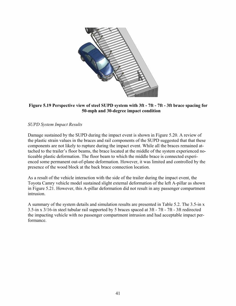
41
Figure 5.19 Perspective view of steel SUPD system with 3ft - 7ft - 7ft - 3ft brace spacing for 50-mph and 30-degree impact condition
SUPD System Impact Results Damage sustained by the SUPD during the impact event is shown in Figure 5.20. A review of the plastic strain values in the braces and rail components of the SUPD suggested that that these components are not likely to rupture during the impact event. While all the braces remained at-tached to the trailer’s floor beams, the brace located at the middle of the system experienced no-ticeable plastic deformation. The floor beam to which the middle brace is connected experi-enced some permanent out-of-plane deformation. However, it was limited and controlled by the presence of the wood block at the back brace connection location.
As a result of the vehicle interaction with the side of the trailer during the impact event, the Toyota Camry vehicle model sustained slight external deformation of the left A-pillar as shown in Figure 5.21. However, this A-pillar deformation did not result in any passenger compartment intrusion.
A summary of the system details and simulation results are presented in Table 5.2. The 3.5-in x 3.5-in x 3/16-in steel tubular rail supported by 5 braces spaced at 3ft - 7ft - 7ft - 3ft redirected the impacting vehicle with no passenger compartment intrusion and had acceptable impact per-formance.

42
Figure 5.20 Perspective view of damage of steel SUPD system with 3ft - 7ft - 7ft - 3ft
brace spacing after 50-mph and 30-degree impact
Figure 5.21 Slight contact damage of left A-pillar during 50-mph and 30-degree impact of steel SUPD system with 3 ft - 7 ft - 7 ft - 3 ft brace spacing
Table 5.2 Summary and results for 50-mph and 30-degree impact into steel SUPD system with 3 ft - 7 ft - 7 ft - 3 ft brace spacing
Material Steel
Rail Cross-Section 3.5-in ×3.5-in ×3/16-in Number of Braces
(Spacing) 5 (3 ft -7 ft -7 ft - 3ft)
Impact Location 4 ft upstream of SUPD mid-span
Result Slight contact with A-pillar; No PCI
Total Weight of SUPD (both sides) 583 lb

43
5.4.2 Steel -- 50 mph Impact Speed and 22.5 deg Impact Angle SUPD System Description and Configuration
The SUPD system consisted of a 3.5-in (high) x 3.5-in (wide) x 3/16-in (thick) steel tubular rail supported by four steel braces spaced at 4 ft, 12 ft, 4 ft, respectively, as shown in Figure 5.22. The Toyota Camry passenger vehicle impacted the SUPD system 3 ft upstream of the SUPD midspan location at a speed of 50 mph and an angle of 22.5 degrees.
Figure 5.22 Side view of steel SUPD system with 4 ft - 12 ft - 4 ft brace spacing for 50-mph
and 22.5-degree impact condition
SUPD System Impact Event Description The SUPD system contained and redirected the impacting passenger vehicle. Maximum deflec-tion of the SUPD during impact was 7.0 inches. The interaction of the vehicle with the SUPD system at time of maximum SUPD system deflection is shown in Figures 5.23 and 5.24.
Figure 5.23 Top view of steel SUPD system with 4 ft - 12 ft - 4 ft brace spacing for 50-mph and 22.5-degree impact condition
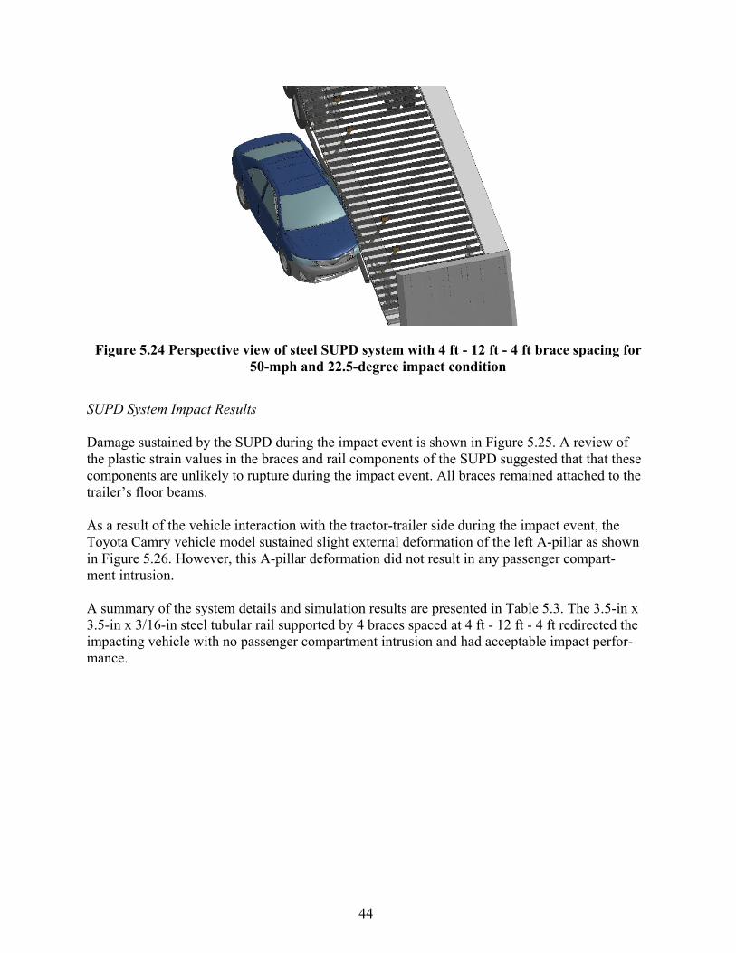
44
Figure 5.24 Perspective view of steel SUPD system with 4 ft - 12 ft - 4 ft brace spacing for 50-mph and 22.5-degree impact condition
SUPD System Impact Results Damage sustained by the SUPD during the impact event is shown in Figure 5.25. A review of the plastic strain values in the braces and rail components of the SUPD suggested that that these components are unlikely to rupture during the impact event. All braces remained attached to the trailer’s floor beams.
As a result of the vehicle interaction with the tractor-trailer side during the impact event, the Toyota Camry vehicle model sustained slight external deformation of the left A-pillar as shown in Figure 5.26. However, this A-pillar deformation did not result in any passenger compart-ment intrusion.
A summary of the system details and simulation results are presented in Table 5.3. The 3.5-in x 3.5-in x 3/16-in steel tubular rail supported by 4 braces spaced at 4 ft - 12 ft - 4 ft redirected the impacting vehicle with no passenger compartment intrusion and had acceptable impact perfor-mance.

45
Figure 5.25 Perspective view of damage of steel SUPD system with 4 ft - 12 ft - 4 ft brace spacing after 50-mph and 22.5-degree impact
Figure 5.26 Slight contact damage of left A-pillar during 50-mph and 22.5-degree im-pact of steel SUPD system with the 4 ft - 12 ft - 4 ft brace spacing
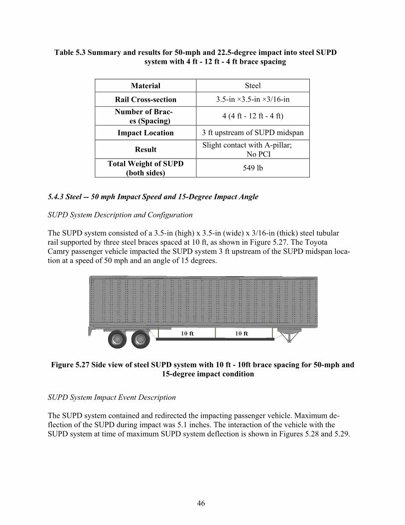
46
Table 5.3 Summary and results for 50-mph and 22.5-degree impact into steel SUPD system with 4 ft - 12 ft - 4 ft brace spacing
Material Steel
Rail Cross-section 3.5-in ×3.5-in ×3/16-in Number of Brac-
es (Spacing) 4 (4 ft - 12 ft - 4 ft)
Impact Location 3 ft upstream of SUPD midspan
Result Slight contact with A-pillar; No PCI
Total Weight of SUPD (both sides) 549 lb
5.4.3 Steel -- 50 mph Impact Speed and 15-Degree Impact Angle SUPD System Description and Configuration
The SUPD system consisted of a 3.5-in (high) x 3.5-in (wide) x 3/16-in (thick) steel tubular rail supported by three steel braces spaced at 10 ft, as shown in Figure 5.27. The Toyota Camry passenger vehicle impacted the SUPD system 3 ft upstream of the SUPD midspan loca-tion at a speed of 50 mph and an angle of 15 degrees.
Figure 5.27 Side view of steel SUPD system with 10 ft - 10ft brace spacing for 50-mph and 15-degree impact condition
SUPD System Impact Event Description The SUPD system contained and redirected the impacting passenger vehicle. Maximum de-flection of the SUPD during impact was 5.1 inches. The interaction of the vehicle with the SUPD system at time of maximum SUPD system deflection is shown in Figures 5.28 and 5.29.

47
Figure 5.28 Top view of steel SUPD system with 10 ft - 10ft brace spacing for 50-mph and 15-degree impact condition
Figure 5.29 Perspective view of steel SUPD system with 10 ft - 10ft brace spacing for 50- mph and 15-degree impact condition
SUPD System Impact Results Damaged sustained by the SUPD during the impact event is shown in Figure 5.30. A review of the plastic strain values in the braces and rail components of the SUPD suggested that that these components are unlikely to rupture during the impact event. All the braces remained attached to the trailer’s floor beams.
The Toyota Camry did not interact with the side of the trailer during the impact event and there was no deformation of the A-pillar as shown in Figure 5.31. Consequently, there was no defor-mation or intrusion into the passenger compartment.

48
A summary of system details and simulation results are presented in Table 5.4. The 3.5-in x 3.5- in x 3/16-in steel tubular rail supported by 3 braces spaced at 10 ft - 10ft redirected the impacting vehicle with no passenger compartment intrusion and had acceptable impact performance.
Figure 5.30 Perspective view of damage of steel SUPD system with 10 ft - 10ft brace spacing
after 50-mph and 15-degree impact
Figure 5.31 No contact or damage of left A-pillar during 50-mph and 15-degree impact of steel SUPD with 10 ft - 10ft brace spacing

49
Table 5.4 Summary and results for 50-mph and 15-degree impact into steel SUPD system with 10 ft - 10ft brace spacing
Material Steel
Rail Cross-section 3.5-in ×3.5-in ×3/16-in Number of Brac-
es (Spacing) 3 (10 ft -10 ft)
Impact Location 3 ft upstream of SUPD mid-span
Result No contact with A-pillar; No PCI
Total Weight of SUPD (both sides) 515 lb
5.5 ALUMINUM SUPD SYSTEM
A system optimization process similar to that described for the steel systems was followed for the aluminum SUPD systems. The researchers iterated system design details to achieve mini-mum weight aluminum SUPD systems that met impact performance criteria for the prescribed impact conditions. This was accomplished for all three impact severities defined by impact an-gles of 30, 22.5, and 15 degrees.
Multiple finite element impact simulations were performed on various SUPD configurations with different component sizes and design characteristics. This primarily involved iteration of rail size and thickness, number of braces, and brace spacing. A list of the simulations conducted for the aluminum SUPD design variations is presented in Table 5.5. The table includes system configuration details and corresponding simulation results categorized by impact severity. Systems in Table 5.5 that are highlighted in yellow represent the final recommended aluminum designs for each impact severity.
With reference to Table 5.5, and using the 30-degree impact angle as an example, the aluminum SUPD system was initially simulated with five equally spaced braces and a 6 in x 6 in x 3/16 in tubular rail member with a weight of 5.11 lb/ft. This system redirected the impacting passenger car without contact or deformation of the A-pillar. The next iteration involved reducing the size of the tubular rail member to 4 in x 6 in x 3/16 in with a weight of 4.24 lb/ft. This configuration also redirected the passenger vehicle without damage to the A-pillar. In the third iteration, the rail size was further reduced to 4 in x 4 in x 3/16 in with a weight of 3.36 lb/ft. This design once again redirected the passenger car without damaging the A-pillar. The next iteration evaluated retained the 4 in x 4 in x 3/16 rail, but reduced the number of supporting braces from five to four. The passenger vehicle penetrated under the trailer and the system performed unacceptably. Therefore, the research team selected the 4 in x 4 in x 3/16 in rail member with 5 braces as the final design for the 30 degree impact condition. The optimization of the aluminum SUPDs for the 22.5 degree and 15 degree impact angles followed a similar iterative process to obtain the

50
final recommended designs. The following sections present details and simulation results for these final recommended designs.
Table 5.5 Finite element impact simulations – Aluminum SUPD systems.
Syste m Details Results
Rail Size
Mate rial
Angle
Numbe
r of Brace s
Span Le ngth (ft)
Impact Location
(ft upstre am midpoint)
Weight (Two Side s, lbs)
A Pillar Contact
Redire ction
4"x4"x3/16" Alumi-
30.0 4 5',10',5' 3 231 Severe None 4"x4"x3/16" Alumi-
30.0 5 5', 5', 5', 5' 3 252 None Yes
4"x4"x3/16" Alumi-
30.0 5 3', 7' ,7', 3' 4 252 Severe Yes 4"x6"x3/16" Alumi-
30.0 4 5',10',5' 3 267 Severe None
4"x6"x3/16" Alumi-
30.0 5 5', 5', 5', 5' 1 288 None Yes 4"x6"x3/16" Alumi-
30.0 5 5', 5', 5', 5' 3 288 None Yes
6"x6"x3/16" Alumi-
30.0 5 5', 5', 5', 5' 1 325 None Yes 6"x6"x3/16" Alumi-
30.0 5 5', 5', 5', 5' 3 325 None Yes
4"x4"x3/16" Alumi-
22.5 4 6', 8', 6' 3 231 Slight Yes 4"x6"x3/16" Alumi-
22.5 4 5',10',5' 3 267 Severe Yes
4"x6"x3/16" Alumi-
22.5 4 6', 8', 6' 3 267 Slight Yes 4"x4"x3/16" Alumi-
15.0 3 10', 10' 5 213 None Yes
4"x4"x3/16" Alumi-
15.0 4 4', 12', 4' 3 231 Slight Yes 4"x6"x3/16" Alumi-
15.0 4 5',10',5' 3 267 None Yes
4"x6"x3/16" Alumi-
15.0 4 5',10',5' 3 267 None Yes
5.5.1 Aluminum -- 50 mph Impact Speed and 30-Degree Impact Angle SUPD System Description and Configuration
The aluminum SUPD system consisted of a 4-in (high) x 4-in (wide) x 3/16-in (thick) aluminum tubular rail supported by five aluminum braces spaced at 5 ft as shown in Figure 5.32. The Toyota Camry passenger vehicle impacted the SUPD system 3 ft upstream of the SUPD mid-span location at a speed of 50 mph and an angle of 30 degrees.
Figure 5.32 Side view of aluminum SUPD system with 5 ft brace spacing for 50-mph and
30-degree impact condition
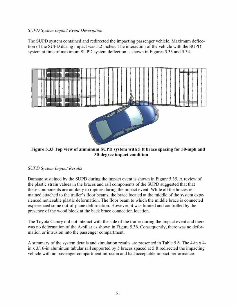
51
SUPD System Impact Event Description The SUPD system contained and redirected the impacting passenger vehicle. Maximum deflec-tion of the SUPD during impact was 5.2 inches. The interaction of the vehicle with the SUPD system at time of maximum SUPD system deflection is shown in Figures 5.33 and 5.34.
Figure 5.33 Top view of aluminum SUPD system with 5 ft brace spacing for 50-mph and
30-degree impact condition
SUPD System Impact Results Damage sustained by the SUPD during the impact event is shown in Figure 5.35. A review of the plastic strain values in the braces and rail components of the SUPD suggested that that these components are unlikely to rupture during the impact event. While all the braces re-mained attached to the trailer’s floor beams, the brace located at the middle of the system expe-rienced noticeable plastic deformation. The floor beam to which the middle brace is connected experienced some out-of-plane deformation. However, it was limited and controlled by the presence of the wood block at the back brace connection location.
The Toyota Camry did not interact with the side of the trailer during the impact event and there was no deformation of the A-pillar as shown in Figure 5.36. Consequently, there was no defor-mation or intrusion into the passenger compartment.
A summary of the system details and simulation results are presented in Table 5.6. The 4-in x 4- in x 3/16-in aluminum tubular rail supported by 5 braces spaced at 5 ft redirected the impacting vehicle with no passenger compartment intrusion and had acceptable impact performance.
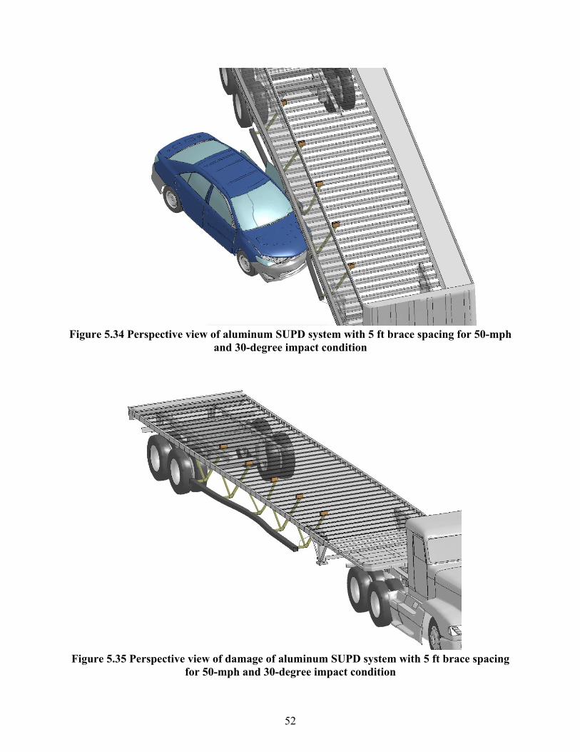
52
Figure 5.34 Perspective view of aluminum SUPD system with 5 ft brace spacing for 50-mph
and 30-degree impact condition
Figure 5.35 Perspective view of damage of aluminum SUPD system with 5 ft brace spacing
for 50-mph and 30-degree impact condition

53
Figure 5.36 No contact or damage of left A-pillar during 50-mph and 30-degree im-pact of aluminum SUPD with 5 ft brace spacing
Table 5.6 Summary and results for 50-mph and 30-degree impact into aluminum SUPD system with 5 ft brace spacing
Material Aluminum
Rail Cross-section 4-in ×4-in ×3/16-in Number of Brac-
es (Spacing) 5 (5 ft -5 ft -5 ft -5 ft)
Impact Location 3 ft upstream of SUPD mid-span
Result No contact with A-pillar; No PCI
Total Weight of SUPD (both sides) 252 lb
5.5.2 Aluminum -- 50 mph Impact Speed and 22.5-Degree Impact Angle SUPD System Description and Configuration
The SUPD system consisted of a 4-in (high) x 4-in (wide) x 3/16-in (thick) aluminum tubular rail supported by four aluminum braces spaced at 6 ft, 8 ft, and 6 ft, respectively, as shown in Figure 5.37. The Toyota Camry passenger vehicle impacted the SUPD system 3 ft upstream of the SUPD midspan location at a speed of 50 mph and an angle of 22.5 degrees.

54
Figure 5.37 Side view of aluminum SUPD system with 6 ft - 8 ft - 6 ft spacing for 50-mph
and 22.5-degree impact condition
SUPD System Impact Event Description The SUPD system contained and redirected the impacting passenger vehicle. Maximum deflec-tion of the SUPD during impact was 9.0 inches. The interaction of the vehicle with the SUPD system at time of maximum SUPD system deflection is shown in Figures 5.38 and 5.39.
Figure 5.38 Top view of aluminum SUPD system with 6 ft - 8 ft - 6 ft brace spacing for
50- mph and 22.5-degree impact condition

55
Figure 5.39 Perspective view of aluminum SUPD system with 6 ft - 8 ft - 6 ft spacing for 50-
mph and 22.5-degree impact condition
SUPD System Impact Results Damage sustained by the SUPD during the impact event is shown in Figure 5.40. A review of the plastic strain values in the braces and rail components of the SUPD suggested that that these components are unlikely to rupture during the impact event. While all the braces remained at-tached to the trailer’s floor beams, some of the braces experienced some plastic deformation. The floor beams to which the braces are connected experienced some out-of-plane deformation. However, it was limited and controlled by the presence of the wood blocks at the back brace connection locations.
As a result of the vehicle interaction with the tractor-trailer side during the impact event, the Toyota Camry vehicle model sustained slight external deformation of the left A-pillar as shown in Figure 5.41. However, this A-pillar deformation did not result in any passenger compartment intrusion.
A summary of the system details and simulation results are presented in Table 5.7. The 4-in x 4- in x 3/16-in aluminum tubular rail supported by 4 braces spaced at 6 ft - 8 ft - 6 ft redirected the impacting vehicle with no passenger compartment intrusion and had acceptable impact perfor-mance.

56
Figure 5.40 Perspective view of damage of aluminum SUPD system with 6 ft - 8 ft - 6
ft brace spacing for 50-mph and 22.5-deg. impact condition
Figure 5.41 Slight contact damage of left A-pillar during 50-mph and 22.5-degree im-pact of aluminum SUPD system with 6 ft - 8 ft - 6 ft brace spacing

57
Table 5.7 Summary and results for 50-mph and 22.5-degree impact into aluminum SUPD system with 6 ft - 8 ft - 6 ft brace spacing
Material Aluminum
Rail Cross-section 4-in ×4-in ×3/16-in Number of Brac-
es (Spacing) 4 (6 ft -8 ft -6 ft)
Impact Location 3 ft upstream of SUPD mid-span
Result Slight contact with A-pillar; No PCI
Total Weight of SUPD (both sides) 231 lb
5.5.3 Aluminum -- 50 mph Impact Speed and 15 deg Impact Angle SUPD System Description and Configuration
The SUPD system consisted of a 4-in (high) x 4-in (wide) x 3/16-in (thick) aluminum tubular rail supported by three aluminum braces spaced at 10 ft as shown in Figure 5.42. The Toyota Camry passenger vehicle impacted the SUPD system 5 ft upstream of the SUPD midspan location at a speed of 50 mph and an angle of 15 degrees.
Figure 5.42 Side view of aluminum SUPD system with 10 ft brace spacing for 50-mph and
15-degree impact condition
SUPD System Impact Event Description The SUPD system contained and redirected the impacting passenger vehicle. Maximum deflec-tion of the SUPD during impact was 5.0 inches. The interaction of the vehicle with the SUPD system at time of maximum SUPD system deflection is shown in Figures 5.43 and 5.44.

58
Figure 5.43 Top view of aluminum SUPD system with 10 ft brace spacing for 50-mph and
15-degree impact condition
Figure 5.44 Perspective view of aluminum SUPD system with 10 ft brace spacing for 50- mph and 15-degree impact condition

59
SUPD System Impact Results Damaged sustained by the SUPD during the impact event is shown in Figure 5.45. A review of the plastic strain values in the braces and rail components of the SUPD suggested that that these components are unlikely to rupture during the impact event. While all the braces remained at-tached to the trailer’s floor beams, the brace located at the middle of the system experienced mi-nor plastic deformation.
The Toyota Camry did not interact with the side of the trailer during the impact event and there was no deformation of the A-pillar as shown in Figure 5.46. Consequently, there was no defor-mation or intrusion into the passenger compartment.
A summary of the system details and simulation results are presented in Table 5.8. The 4-in x 4- in x 3/16-in aluminum tubular rail supported by 3 braces spaced at 10 ft redirected the impacting vehicle with no passenger compartment intrusion and had acceptable impact performance.
Figure 5.45 Perspective view of damage of the SUPD system with 10 ft brace spacing (50- mph and 15-degree impact conditions)

60
Figure 5.46 No contact or damage of left A-pillar during 50-mph and 15-degree im-pact of aluminum SUPD with 10 ft brace spacing
Table 5.8 Summary and results for 50-mph and 15-degree impact into aluminum SUPD system with 3 braces and 10 ft brace spacing
Material Aluminum
Rail Cross-section 4-in ×4-in ×3/16-in Number of Brac-
es (Spacing) 3 (10 ft)
Impact Location 5 ft upstream of SUPD mid-span
Result No contact with A-pillar; No PCI
Total Weight of SUPD (both sides) 213 lb
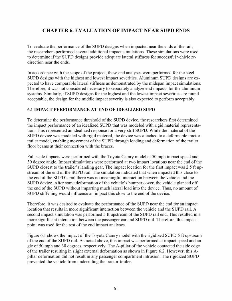
61
CHAPTER 6. EVALUATION OF IMPACT NEAR SUPD ENDS
To evaluate the performance of the SUPD designs when impacted near the ends of the rail, the researchers performed several additional impact simulations. These simulations were used to determine if the SUPD designs provide adequate lateral stiffness for successful vehicle re-direction near the ends.
In accordance with the scope of the project, these end analyses were performed for the steel SUPD designs with the highest and lowest impact severities. Aluminum SUPD designs are ex-pected to have comparable lateral stiffness as demonstrated by the midspan impact simulations. Therefore, it was not considered necessary to separately analyze end impacts for the aluminum systems. Similarly, if SUPD designs for the highest and the lowest impact severities are found acceptable, the design for the middle impact severity is also expected to perform acceptably.
6.1 IMPACT PERFORMANCE AT END OF IDEALIZED SUPD
To determine the performance threshold of the SUPD device, the researchers first determined the impact performance of an idealized SUPD that was modeled with rigid material representa-tion. This represented an idealized response for a very stiff SUPD. While the material of the SUPD device was modeled with rigid material, the device was attached to a deformable tractor-trailer model, enabling movement of the SUPD through loading and deformation of the trailer floor beams at their connection with the braces.
Full scale impacts were performed with the Toyota Camry model at 50 mph impact speed and 30 degree angle. Impact simulations were performed at two impact locations near the end of the SUPD closest to the trailer’s landing gear. The impact location for the first impact was 2.5 ft up-stream of the end of the SUPD rail. The simulation indicated that when impacted this close to the end of the SUPD’s rail there was no meaningful interaction between the vehicle and the SUPD device. After some deformation of the vehicle’s bumper cover, the vehicle glanced off the end of the SUPD without imparting much lateral load into the device. Thus, no amount of SUPD stiffening would influence an impact this close to the end of the device.
Therefore, it was desired to evaluate the performance of the SUPD near the end for an impact location that results in more significant interaction between the vehicle and the SUPD rail. A second impact simulation was performed 5 ft upstream of the SUPD rail end. This resulted in a more significant interaction between the passenger car and SUPD rail. Therefore, this impact point was used for the rest of the end impact analyses.
Figure 6.1 shows the impact of the Toyota Camry model with the rigidized SUPD 5 ft upstream of the end of the SUPD rail. As noted above, this impact was performed at impact speed and an-gle of 50 mph and 30 degrees, respectively. The A-pillar of the vehicle contacted the side edge of the trailer resulting in slight external deformation as shown in Figure 6.2. However, this A- pillar deformation did not result in any passenger compartment intrusion. The rigidized SUPD prevented the vehicle from underriding the tractor-trailer.

62
(a)
(b)
(c)
Figure 6.1 Top view of the impact with rigidized SUPD system near the end of the
SUPD rail. (a) Vehicle shown at the time of impact with the SUPD, (b) vehicle at the time of maximum A-pillar deformation, and (c) vehicle at the end of the simulation.

63
Figure 6.2 Passenger car after 50 mph and 30-degree impact near end of rigidized SUPD 6.2 IMPACT PERFORMANCE AT END OF DEFORMABLE SUPD
The researchers performed impact analyses near the end of the SUPD rail for both the highest (30 degree) and lowest (15 degree) impact severity steel SUPD designs. The impact location was 5 ft upstream of the SUPD end nearest to the landing gear. The Toyota Camry model im-pacted the SUPD systems at a speed of 50 mph.
Figure 6.3 shows the impact of the Toyota Camry model with the highest severity SUPD design. This system has five braces spaced at 3-ft, 7-ft, 7-ft, and 3-ft. As discussed in Chapter 5, the brace spacing at the end of the SUPD system was reduced to help accommodate impacts near the end of the rail. In this impact simulation, the A-pillar of the vehicle contacted the side edge of the trailer, resulting in external deformation as shown in Figure 6.4. This A-pillar deformation resulted in a small internal occupant compartment deformation of 2.2 inches laterally inward toward the passenger-side A-Pillar, and approximately 0.5 inch longitudinally toward the driver- side C-pillar. The deformed state of the SUPD is shown in Figure 6.5. The SUPD design suc-cessfully prevented the impacting vehicle from wedging underneath the tractor-trailer.
Figure 6.6 shows the impact of the Toyota Camry model with the lowest severity steel SUPD de-sign. This system has three braces spaced at 10 ft. In this impact simulation, the A-pillar of the vehicle contacted the side edge of the trailer, resulting in slight external deformation as shown in Figure 6.7. However, this A-pillar deformation did not result in passenger compartment intru-sion. The damage to the vehicle after the impact is shown in Figure 6.7. The deformed state of the SUPD is shown in Figure 6.8. The SUPD design successfully prevented the impacting vehi-cle from wedging underneath the tractor-trailer.

64
(a)
(b)
(c)
Figure 6.3 Top view of the highest severity steel SUPD system for impact near the end of the SUPD rail. (a) Vehicle shown at the time of impact with the SUPD, (b) vehicle at the
time of maximum A-pillar deformation, and (c) vehicle at the end of the simulation.
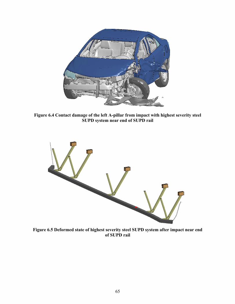
65
Figure 6.4 Contact damage of the left A-pillar from impact with highest severity steel SUPD system near end of SUPD rail
Figure 6.5 Deformed state of highest severity steel SUPD system after impact near end
of SUPD rail
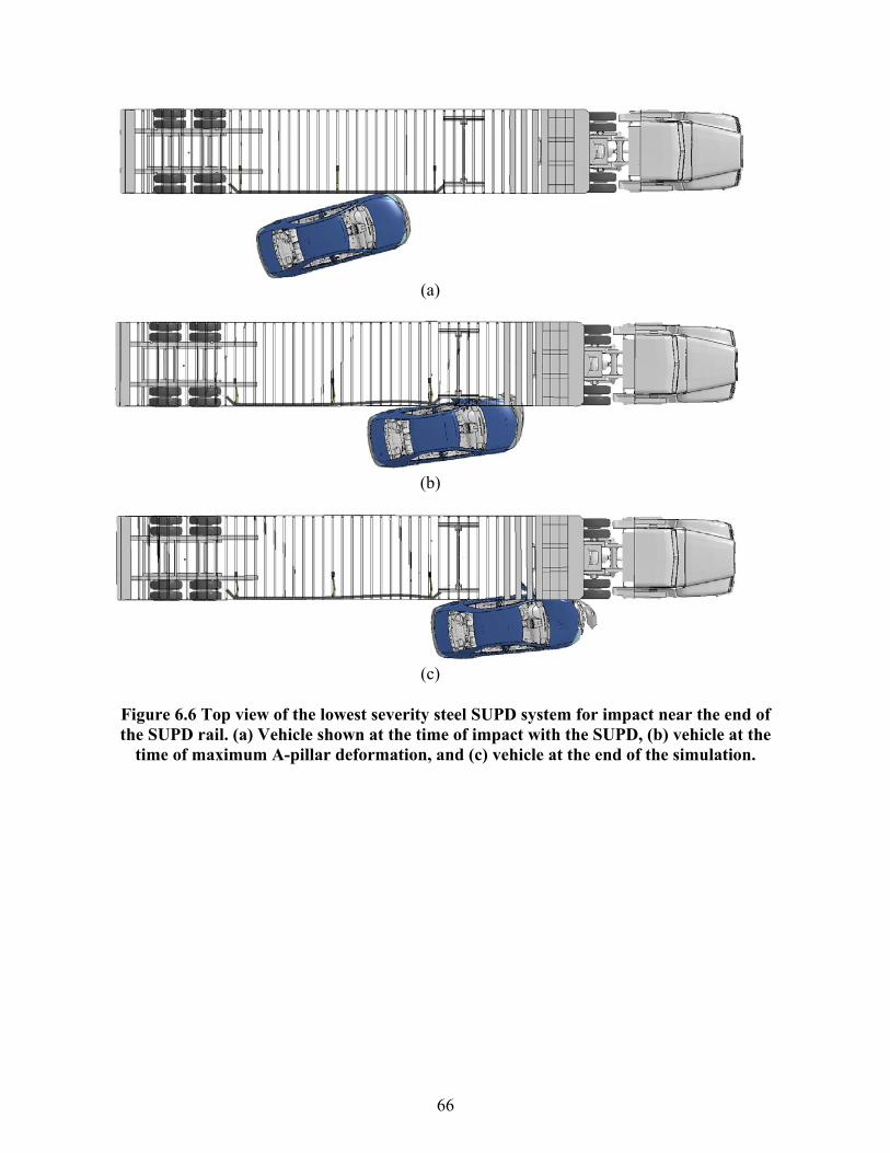
66
(a)
(b)
(c)
Figure 6.6 Top view of the lowest severity steel SUPD system for impact near the end of the SUPD rail. (a) Vehicle shown at the time of impact with the SUPD, (b) vehicle at the
time of maximum A-pillar deformation, and (c) vehicle at the end of the simulation.

67
Figure 6.7 Slight contact damage of the driver-side A-pillar for impact near the end of the
lowest severity steel SUPD rail.
Figure 6.8 Deformed state of lowest severity steel SUPD system after impact near end of
SUPD rail 6.3 CONCLUSIONS
Based on the results of the impact simulations described in this chapter, it can be concluded that the SUPD designs are expected to perform acceptably for impacts near the ends of the SUPD. Some internal occupant compartment deformation of the impact side A-pillar was observed for the highest severity impact system, but the injury risk associated with this level of deformation in this area is considered low. In the case of the lowest severity design, there was no internal occu-pant deformation of the A-pillar. In both cases, the vehicle was successfully prevented from wedging under the tractor-trailer vehicle. While the middle impact severity design (i.e. impact at 22.5 degree angle) was not simulated, its performance is expected to be bracketed by the highest and lowest severity designs and, thus, should also have acceptable impact performance

68
CHAPTER 7. GAP IMPACT EVALUATION
In this project, the SUPD designs have been developed around the functional constraints of a typical tractor-trailer vehicle. While most of the hazardous region on the sides of a tractor-trailer is shielded by the SUPD designs, there are gaps around the landing gear and the rear tan-dem bogie that are still unshielded. These gaps are needed to accommodate movement of the rear bogie tandem and to provide access to the landing gear.
The research team performed four additional simulations to evaluate the interaction between the trailer and a passenger car into these unshielded regions. As shown in Figure 7.1, two impact simulations (one in each direction of travel) were performed for the gap at the landing gear area of the tractor-trailer. Two additional impact simulations (one in each direction) were performed for the gap at the rear tandem bogie of the trailer. All impacts were performed for the highest severity conditions, i.e., impact speed of 50 mph and impact angle of 30 degrees.
Figure 7.1 Four impact points shown for the gap impact evaluation. Various parts of the model are not shown to highlight the relative locations of the SUPD rail, landing gear, and
rear tandem bogie. These impacts were expected to result in significant material failure and metal tearing due to underride of the passenger car. Since the finite element models of the passenger car and the tractor-trailer do not have such material failure modes built into most parts, the simulations were performed up to a time that the computations terminated due to numerical instabilities. The results can be considered valid up to the point of termination.
7.1 IMPACT AT LANDING GEAR GAP
The two impacts into the side of the trailer at the landing gear were performed with the passenger car traveling in both directions as depicted in Figure 7.1. The impact directed toward the front of the trailer was performed such that the impacting passenger car just missed the end of the SUPD rail.
Figure 7.2 shows the passenger car underneath the trailer at the time the simulation terminated. As shown in Figure 7.3, the damage to the passenger car is severe. The results show that the ve-hicle wedges underneath the trailer, impacting first the landing gear and then the rear tandem of the tractor.
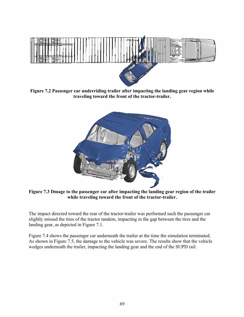
69
Figure 7.2 Passenger car underriding trailer after impacting the landing gear region while
traveling toward the front of the tractor-trailer.
Figure 7.3 Dmage to the passenger car after impacting the landing gear region of the trailer
while traveling toward the front of the tractor-trailer. The impact directed toward the rear of the tractor-trailer was performed such the passenger car slightly missed the tires of the tractor tandem, impacting in the gap between the tires and the landing gear, as depicted in Figure 7.1.
Figure 7.4 shows the passenger car underneath the trailer at the time the simulation terminated. As shown in Figure 7.5, the damage to the vehicle was severe. The results show that the vehicle wedges underneath the trailer, impacting the landing gear and the end of the SUPD rail.

70
Figure 7.4 Passenger car underneath the trailer after impacting the landing gear region
while traveling toward the rear of the tractor-trailer.
Figure 7.5 Damage to the passenger car after impacting the landing gear region while travel-
ing toward the rear of the tractor-trailer. 7.2 IMPACT AT REAR TRAILER TANDEM GAP
The two impacts in the rear tandem bogie region of the trailer were performed in both directions as illustrated in Figure 7.1. The impact directed toward the front of the trailer was performed such that the impacting passenger car slightly missed the tires of the rear trailer tandem, targeting the gap between the tires and the SUPD rail.
Figure 7.6 shows the results of the simulation at the time the simulation terminated due to ele-ment distortion. Figure 7.7 shows the damage to the vehicle at the time of simulation termina-tion. Although the simulation results are not conclusive at the time the run terminated, they indi-cate that deformation of the A-pillar is likely to occur due to the impact of the passenger car with the edge of the trailer.

71
Figure 7.6 Passenger car impact with the tractor-trailer in the rear tandem region while traveling toward the front of the tractor-trailer
Figure 7.7 Damage to the passenger car after impacting the rear tandem region while traveling toward the front of the tractor-trailer.
The impact directed toward the rear of the trailer was performed such that the impacting pas-senger car slightly missed the end of the SUPD rail, targeting the gap between the tires and the SUPD system.
Figure 7.8 shows the results of the simulation at the time of maximum lateral movement of the trailer’s rear trailer tandem. The vehicle engaged the wheels and tires of the rear trailer tandem and yawed clockwise. There was no measurable deformation of the A-pillar due to the impact. Figure 7.9 shows the deformed state of the vehicle after the impact.

72
Figure 7.8 Passenger car impact with the tractor-trailer in the rear tandem region while traveling toward the rear of the tractor-trailer
Figure 7.9 Damage to the passenger car after impacting the rear tandem region while traveling toward the rear of the tractor-trailer.

73
CHAPTER 8. SUPD DESIGN RELATIONSHIPS
The optimization studies described in this report have resulted in recommended SUPD systems that are designed to accommodate a specified level of impact severity. For an oblique impact, the impact severity is prescribed by the vehicle weight, impact speed, and impact angle as de-fined below:
Impact Severity (I.S.) = ½ M [V Sin(θ)]2
where M = vehicle mass, V = impact speed, and θ = impact angle. It is essentially, the lateral energy that must be managed by the SUPD.
A given impact severity defines an associated dynamic impact load that dictates the required strength of the SUPD to meet performance requirements. For each impact severity, the weight of the SUPD was minimized subject to acceptable impact performance. Acceptable impact perfor-mance was defined as containment and redirection of the impacting vehicle without passenger compartment intrusion. This was accomplished for two different common materials (steel and aluminum) for three different impact severities. Since the different sets of impact conditions all involved a 3,215-lb Toyota Camry impacting at a speed of 50 mph, they were differentiated by three chosen impact angles – 30, 22.5, and 15 degrees.
It is anticipated that as more crash data becomes available and the characteristics of vehicle im-pacts into the sides of trailers are better quantified and understood, the design impact conditions that are ultimately prescribed may differ from those used under this project. The results of this project have been used to develop relationships between SUPD weight, impact severity, and lateral force to assist with the extension and application of this work to other impact scenarios.
Figure 8.1 presents the relationship between total optimized weight of the SUPD (both sides) and the impact severity it can accommodate. Separate plots are provided for the steel and alumi-num systems. These plots are shown on a smaller y-axis scale in Figure 8.2 and Figure 8.3 for the steel and aluminum systems, respectively. These relationships can be used to estimate the weight of an SUPD for a prescribed set of impact conditions or, conversely, to understand the impact severity that can be accommodated by a given SUPD weight.
For example, what is the estimated weight of a steel SUPD system designed to accommodate an impact with a 3,215-lb Toyota Camry at a speed of 60 mph and an angle of 20 degrees? The im-pact severity associated with the given set of impact conditions is 45 kip-ft. With reference to Figure 8.2, for an impact severity of 45 kip-ft, the estimated weight of a steel SUPD system (both sides) would be approximately 555 lb.
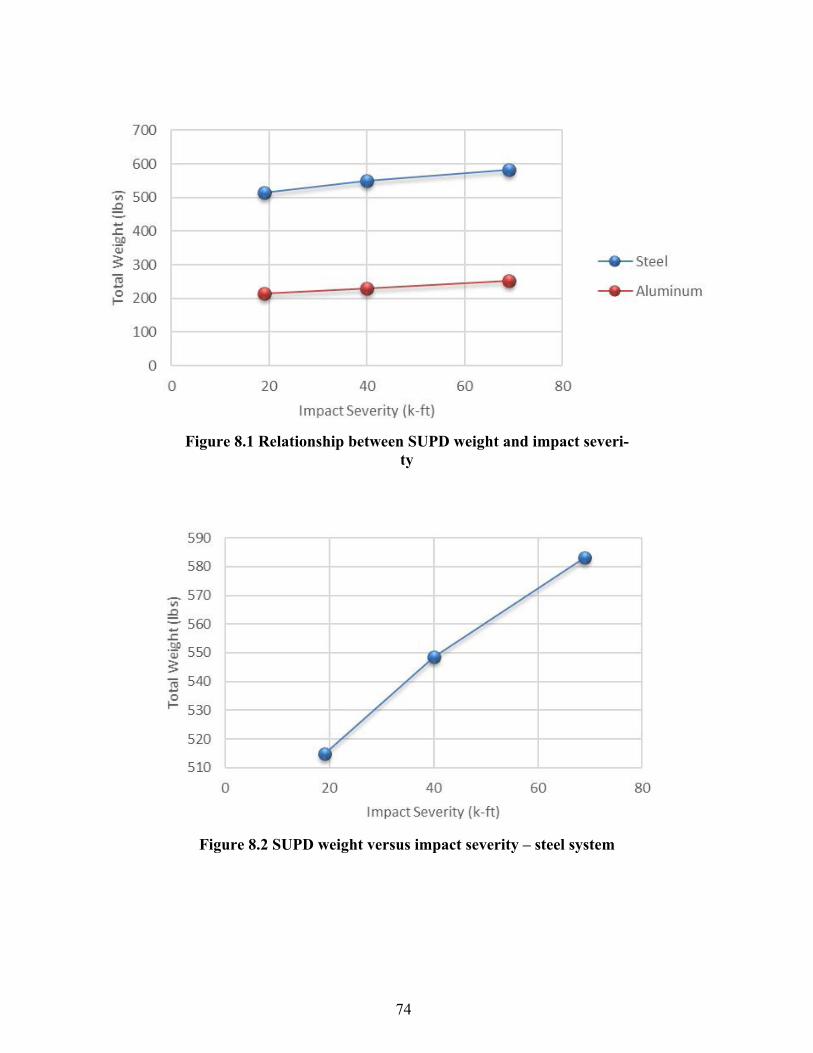
74
Figure 8.1 Relationship between SUPD weight and impact severi-
ty
Figure 8.2 SUPD weight versus impact severity – steel system

75
Figure 8.3 SUPD weight versus impact severity – aluminum system
As another example, for an aluminum SUPD system with a total weight (both sides) of 245 lb, what is the impact speed that can be accommodated if a 3,215-lb Toyota Camry impacts at 25 degrees? With reference to Figure 8.3, the impact severity corresponding to a 245-lb aluminum SUPD is approximately 60 kip-ft. Setting the impact severity equation to 60 kip-ft and solving for velocity, the maximum impact speed that can be accommodated by the aluminum SUPD for the prescribed vehicle weight and impact angle is approximately 56 mph.
Figure 8.4 presents a relationship between lateral design load and impact severity. This relation-ship was developed by plotting the impact forces obtained for each of the three impact severi-ties used in this project for the design of the SUPD systems. If a maximum design weight for the SUPD is selected, an impact severity that defines its performance limits can be determined from Figure 8.1. The impact severity, which establishes the range of impact conditions that can be safely accommodated by the device, can then be used in Figure 8.4 to select a corresponding lateral impact load that the SUPD should be designed to withstand.
Given that SUPD design criteria have not yet been established, the design relationships present-ed herein, in addition to the various optimized SUPD designs, will enhance the value of this re-search. The design guidance is intended to provide a greater understanding of how various im-pact speed and angle combinations (i.e. impact severities) influence the weight and performance of the SUPD. Similarly, it provides insight on the range of impact conditions accommodated by an SUPD with a prescribed weight.

76
Figure 8.4 Lateral design load versus impact severity relationship
77
CHAPTER 9. SUMMARY AND CONCLUSIONS
Use of SUPDs has been suggested to mitigate passenger car underride severity during im-pacts with the side of a tractor-van trailer. Past studies have focused on designing SUPDs for 90-degree impacts with passenger cars. The limited data that is available suggests that some impacts with the side of a trailer occur at angles less than 90 degrees. If an SUPD is designed for oblique angle impacts, it is possible to further reduce the weight of the SUPDs, thus mak-ing them more favorable for use on heavy trucks. This project examined the interaction be-tween impact angle and side underride guard weight. The impact angles were chosen to study the sensitivity of the optimum design weight versus impact requirements.
The objective of this research study was to evaluate the design requirements and safety per-formance of SUPDs subjected to oblique impacts with passenger cars through finite element impact simulations. SUPDs were successfully designed for oblique angle impacts of different severity. The impact conditions involved a Toyota Camry passenger car impacting the SUPD at a speed of 50 mph and angles of 30, 22.5, and 15 degrees. Impact simulations were used to evaluate the performance of the SUPDs for impacts along the length and near the ends of the systems.
The research approach included optimization methods intended to minimize weight while re-directing the impacting vehicle without passenger compartment intrusion. It was found that the minimum weight of the SUPD is a function of the design impact severity. Higher impact severities, which are associated with higher impact angles, require an SUPD that is stronger and stiffer than an SUPD designed for lower impact severities. Results of this project provide relationships between SUPD weight, impact conditions, and lateral loading. This information provides both decision makers and designers with a greater understanding of the requirements of SUPDs designed for oblique angle impacts. For example, the minimum weight or lateral design load can be estimated for a selected impact severity. Similarly, the relationships can be used to determine the range of impact conditions that can be accommodated by an SUPD of a selected weight.
The SUPDs were analyzed and designed for two different material types: an ASTM A500 Gr. B steel with a yield strength of 46 ksi, and 6061-T6 aluminum with a yield strength of 40 ksi. Both the steel and aluminum systems are comprised of readily available tubular components. The steel systems are easier to fabricate and attach to the steel frame of the trailer. The aluminum systems offer superior strength-to-weight ratio, which makes them significantly lighter, but spe-cial consideration must be given to the connection to the steel trailer frame to avoid galvanic corrosion.
9.1 STEEL SUPD SYSTEMS
The highest impact severity evaluated under the project included an impact speed of 50 mph and an impact angle of 30 degrees. The final steel SUPD system optimized for this set of impact conditions weighs 583 lb. Note that this weight is the total for all SUPD components deployed

78
on both sides of the trailer. The system details include a 3.5-in ×3.5-in ×3/16-in tubular steel rail element supported by five tubular steel braces spaced at 3 ft -7 ft -7 ft - 3ft along the 20-ft length of the SUPD. The tubular steel braces are comprised of the following parts and members.
• 2 inch x 2 inch x 12-gauge (0.105 inch) thick rear diagonal member, • 1 ½ inch x 1 ½ inch x 14-gauge thick front diagonal member, • 2 inch x 2 inch x 12-gauge (0.105 inch) front horizontal member, and • 12-gauge gusset plate
The steel system for the 22.5 degree impact angle weighs 549 lb. It incorporates the same rail element and braces, but has only four braces at spacing of 4 ft - 12 ft - 4 ft. Finally, the steel sys-tem for the 15 degree impact angle weighs 515 lb. It also incorporates the same rail element and braces, but has only three braces spaced at 10 ft increments.
9.2 ALUMINUM SUPD SYSTEMS
The final optimized aluminum SUPD designed for a 30 degree impact angle has a total weight (both sides of the trailer) of 252 lb. The system includes a 4-in ×4-in ×3/16-in tubular aluminum rail element supported by five tubular steel braces spaced at equal 5 ft increments along the 20-ft length of the SUPD. The tubular steel braces are comprised of the following parts and members.
• 2 inch x 2 inch x 3/16-inch thick rear diagonal member, • 1 ½ inch x 1 ½ inch x 1/8-inch thick front diagonal member, • 2 inch x 2 inch x ¼-inch front horizontal member, and • ¼-inch gusset plate
The aluminum SUPD system for the 22.5 degree impact angle weighs 231 lb. It incorporates the same rail element and braces, but has only four braces at spacing of 6 ft -8 ft -6 ft. Finally, the steel system for the 15 degree impact angle weighs 213 lb. It also incorporates the same rail el-ement and braces, but has only three braces spaced at 10 ft increments.

79
REFERENCES
Blower, D., & Woodrooffe, J. (2013). Heavy-vehicle crash data collection and analysis to charac-terize rear and side underride and front override in fatal truck crashes (Report No. DOT HS 811 725). Washington, DC: National Highway Traffic Safety Administration. Available at www.nhtsa.gov/sites/nhtsa.dot.gov/files/811725.pdf
Bodapati, V. K. K. (2006). Evaluation of energy absorbing pliers underride guard for rear and
side of large trucks (master’s degree thesis). Kansas: Wichita State University. Available at https://soar.wichita.edu/bitstream/handle/10057/617/t06116.pdf?sequence=3&isAllowed=y
Center for Collision Safety and Analysis. (2016, May). Development & Validation of a Finite Ele-
ment Model for the 2012 Toyota Camry Passenger Sedan (Tech summary). Fairfax, VA: George Mason University. doi:10.13021/G8N889. Retrieved from www.ccsa.gmu.edu/wp-content/uploads/2016/06/2012-toyota-camry-tech-summary-v5.pdf
Galipeau-Bélair, P. (2014) Design and development of side underride protection devices (supd) for
heavy vehicles (master’s degree thesis) Canada: University of Ontario Institute of Technol-ogy.
Galipeau-Belair, P., Ghantae, S., Critchley, D., Ramachandra, S., & El-Gindy, M. (2014). Opti-
mized rigid side underride protection device designs for tractor-trailers and straight trucks (SAE Technical Paper 2014-01-0565). Warrendale, PA: SAE International.
Hallquist, J. O. (2016). LS-DYNA keyword user’s manual Livermore, CA: Livermore Software
Technology Corporation. Roux, W., Nagy, A., Gandikota, I., Witowski, K., Svedin, Å, Ho, P., & Zhao, Y. (2016, Novem-
ber). LS-TaSC user's manual, Version 3.2. Livermore, CA: Livermore Software Technology Corporation. Available at www.lsoptsupport.com/documents/manuals/ls-tasc/ls-tasc-3.2-manuals/User_Manual.0.pdf
Stander, N., Roux, W., Basudhar, A., Eggleston, T., Goel, T., & Craig, K. (2015, December). LS-
OPT user's manual, Version 5.2. Livermore, CA: Livermore Software Technology Corpo-ration. Available at www.lsoptsupport.com/documents/manuals/ls-opt/ls-opt-5.2-manual/at_download/file

DOT HS 812 522 April 2018