Embed Size (px)
Citation preview
242 JOHNS HOPKINS APL TECHNICAL DIGEST, VOLUME 25, NUMBER 3 (2004)
M. ARMAND ET AL.
T
Computer-Aided Orthopedic Surgery with Near-Real-Time Biomechanical Feedback
Mehran Armand, Jyri V. S. Lepistö, Andrew C. Merkle, Kaj Tallroth, Xiaofeng Liu, Russell H. Taylor, and James Wenz
his article describes our ongoing efforts in computer-aided surgery. We are develop-ing and testing a biomechanical guidance system that will interact with the surgeon and report the biomechanical state of the joint during hip surgery. The system uses informa-tion from the imagery of a computer-assisted navigation system and displays the contact pressure distribution in the hip joint as the joint realignment is modifi ed intraoperatively. We describe the use of the presented technique for preoperative planning, assessment of surgical outcome, and validation of results as well as intraoperative applications. Although the focus of this work is on periacetabular hip osteotomy, applications of this research can be extended to other types of hip osteotomies, joint osteotomies, and total joint replace-ment techniques.
INTRODUCTION Computer-aided surgery (CAS) systems provide
a broad range of technologies to surgeons before and during surgical procedures. Examples of these tech-nologies include navigation systems, computer models, robotic assisted tools, and visualization devices. CAS systems can be used as both training and research tools and in routine clinical practice. CAS enables the sur-geon to develop new, more accurate, and less invasive surgical techniques. In orthopedic surgery, CAS sys-tems combining preoperative modeling and planning with navigational or robotic intraoperative assistance are becoming increasingly accepted among surgeons. The individual applications may differ, but the funda-mental paradigm of these systems is as follows:
• Patient-specifi c preoperative planning through cre-ation of three-dimensional (3D) virtual environ-ments using medical imagery
• Intraoperative registration of the virtual environ-ment (which includes the patient model and the surgical plan) to the actual patient and the interven-tional system
• Computer-assisted execution of the plan using a vari-ety of technologies
This paradigm—combining preoperative planning, registration, and execution—has been discussed exten-sively by various authors,1–4 including a co-author of this article.5–8
JOHNS HOPKINS APL TECHNICAL DIGEST, VOLUME 25, NUMBER 3 (2004) 243
COMPUTER-AIDED ORTHOPEDIC SURGERY
Patient-Specifi c Planning Computer-aided preoperative planning for orthope-
dic surgery aims at creating virtual environments using 3D reconstructed computed tomography (CT) images and radiographs. In orthopedic applications for the hip, preoperative planning is commonly developed for oste-otomies9–12 and total hip replacements.13–17 Many stud-ies have demonstrated the importance of biomechanical analyses for preoperative planning environments.18–22 Few preoperative environments, however, include detailed biomechanical planning. Rather, they are com-monly based on the kinematics and geometrical analysis of the patient’s anatomy. One reason is that the devel-opment of high-quality patient-specifi c biomechanical models, such as fi nite element models (FEMs), obtained from 3D images is not an automated process, and simu-lations take a considerable amount of time. These tech-niques are less desirable for the structural optimization scheme usually required for surgical planning.
Computer-Assisted Registration and Execution of the Plan
The most common systems for CAS execution use some sort of 3D tracking device to sense the relative positions of the surgical instruments in the surgical fi eld. The coordinate system of the tracking device is registered to the patient and to the preoperative images. Interactive displays are often used to provide informa-tion that helps the surgeon perform the surgery. These types of systems have been applied extensively in ortho-pedics,23–28 neurosurgery, and craniofacial and maxil-lofacial surgery. To our knowledge, the available systems do not provide intraoperative biomechanical informa-tion to the surgeon. Therefore, any modifi cation to the surgical plan during the surgery would deal only with geometrical constraints.
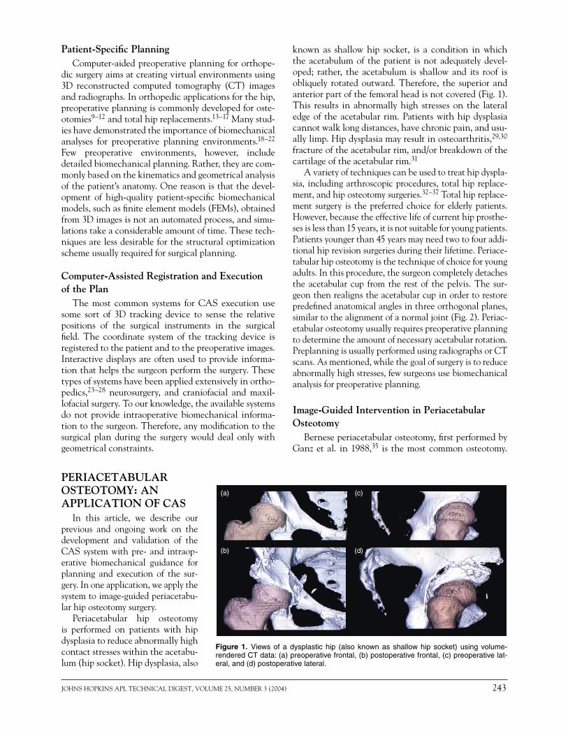
known as shallow hip socket, is a condition in which the acetabulum of the patient is not adequately devel-oped; rather, the acetabulum is shallow and its roof is obliquely rotated outward. Therefore, the superior and anterior part of the femoral head is not covered (Fig. 1). This results in abnormally high stresses on the lateral edge of the acetabular rim. Patients with hip dysplasia cannot walk long distances, have chronic pain, and usu-ally limp. Hip dysplasia may result in osteoarthritis,29,30 fracture of the acetabular rim, and/or breakdown of the cartilage of the acetabular rim.31
A variety of techniques can be used to treat hip dyspla-sia, including arthroscopic procedures, total hip replace-ment, and hip osteotomy surgeries.32–37 Total hip replace-ment surgery is the preferred choice for elderly patients. However, because the effective life of current hip prosthe-ses is less than 15 years, it is not suitable for young patients. Patients younger than 45 years may need two to four addi-tional hip revision surgeries during their lifetime. Periace-tabular hip osteotomy is the technique of choice for young adults. In this procedure, the surgeon completely detaches the acetabular cup from the rest of the pelvis. The sur-geon then realigns the acetabular cup in order to restore predefi ned anatomical angles in three orthogonal planes, similar to the alignment of a normal joint (Fig. 2). Periac-etabular osteotomy usually requires preoperative planning to determine the amount of necessary acetabular rotation. Preplanning is usually performed using radiographs or CT scans. As mentioned, while the goal of surgery is to reduce abnormally high stresses, few surgeons use biomechanical analysis for preoperative planning.
Image-Guided Intervention in Periacetabular Osteotomy
Bernese periacetabular osteotomy, fi rst performed by Ganz et al. in 1988,35 is the most common osteotomy.
Figure 1. Views of a dysplastic hip (also known as shallow hip socket) using volume-rendered CT data: (a) preoperative frontal, (b) postoperative frontal, (c) preoperative lat-eral, and (d) postoperative lateral.
PERIACETABULAR OSTEOTOMY: AN APPLICATION OF CAS
In this article, we describe our previous and ongoing work on the development and validation of the CAS system with pre- and intraop-erative biomechanical guidance for planning and execution of the sur-gery. In one application, we apply the system to image-guided periacetabu-lar hip osteotomy surgery.
Periacetabular hip osteotomy is performed on patients with hip dysplasia to reduce abnormally high contact stresses within the acetabu-lum (hip socket). Hip dysplasia, also
244 JOHNS HOPKINS APL TECHNICAL DIGEST, VOLUME 25, NUMBER 3 (2004)
M. ARMAND ET AL.
This technically challenging technique consists of a sequence of cuts through the ischium, pubis, and ilium using various surgical instruments. The procedure com-pletely detaches the acetabular cup from the rest of the pelvis. The cup is then realigned and fi xed to the pelvis to improve the femoral head coverage and contact pres-sure distribution in the hip joint (Fig. 1). During surgery, the surgeon must perform some of the chiseling without having a clear view of the surgical instruments. In addi-tion, there is always a potential to damage the neural and vascular structures near the site of surgical activ-ity.35 Therefore, this surgery can benefi t greatly from the use of image-guided navigation systems, which are more widely used for total joint replacement surgeries. Langlotz et al.38 reported on the fi rst 12 cases of the use of free-hand navigation for periacetabular osteotomy. They found no intraoperative or postoperative compli-cations. Other recent examples include intraoperative navigation for the Kingston periacetabular osteotomy.39 The Kingston osteotomy has been reported on eight patients, with successful results in seven of the cases. This technique offers a less challenging approach; how-ever, it requires an extra step of detachment of the femo-ral head.
Few other surgeons in the world use image-guided navigation for periacetabular osteotomy surgeries. Per-haps the broad clinical application is hindered by high costs, additional time required during the intervention, problems regarding the surgeon/machine interface, and space constraints in the operating room. Never-theless, we feel the benefi ts regarding the added safety and precision of the surgery, and the possibility of integrating preoperative planning with intraoperative
navigation, remain attractive. Currently a co-author of this article, Dr. Lepistö, is one of the few surgeons who perform image-guided periacetabular osteotomies.
Intraoperative Revision of the Preoperative PlanThe current state of research has shown the advan-
tages and importance of using biomechanics and joint contact pressure calculations in planning the periac-etabular osteotomy.9,19,21 For the following reasons a signifi cant improvement can be obtained if the surgeon can intraoperatively access and visualize the biome-chanical state of the surgery:
• There is a degree of unpredictability in the fi nal fi xation of the bone fragment because of variations in quality, the thickness of cortical structures, and the fi nal shape of the cut of the bone fragment. Because of concerns regarding secure fi xation and bone healing, trade-offs in alignment are often necessary. The interactive biomechanical guidance system (BGS), therefore, can help the surgeon to revise the plan in real time and fi nd the new optimal fi xation.
• Bone or soft tissue impingement may become evi-dent during surgery, requiring the surgeon to revise the plan and consider an alternative alignment.
• If the realignment strategy is modifi ed as a result of either of the above conditions, the joint congruency needs to be re-checked. Simultaneous femoral oste-otomy may have to be considered in order to improve congruency.
• Conducting an intraoperative range-of-motion test of the hip provides a better assessment of joint stability.
Desired Characteristics of a Biomechanical Guidance System
To perform near-real-time contact pressure calcula-tions and biomechanical analysis, a fast and accurate algorithm is required. In addition, since the technique will be used in a surgical environment, the biomechani-cal model should work with minimal free parameters to promote ease of use. FEMs are the most detailed and accurate modeling technique used to calculate the stress distribution in bones and around joints; however, they have a signifi cantly long run time. When contact sur-faces and dynamic loadings (time-dependent loads) are presented in the FEM, the simulation may take several hours. Thus, it is prohibitive to apply detailed FEMs for individually based functional data.
The discrete element analysis (DEA) technique,20,40,41 in contrast, is extremely fast. A typical simulation that may take days to perform using FEMs can be completed in a few seconds with the DEA technique. It is espe-cially suitable when there is a drastic difference among the stiffness properties of the materials used in simu-lation (e.g., bone and cartilage). In addition, the tech-nique is fault tolerant and forgiving of inaccuracies when
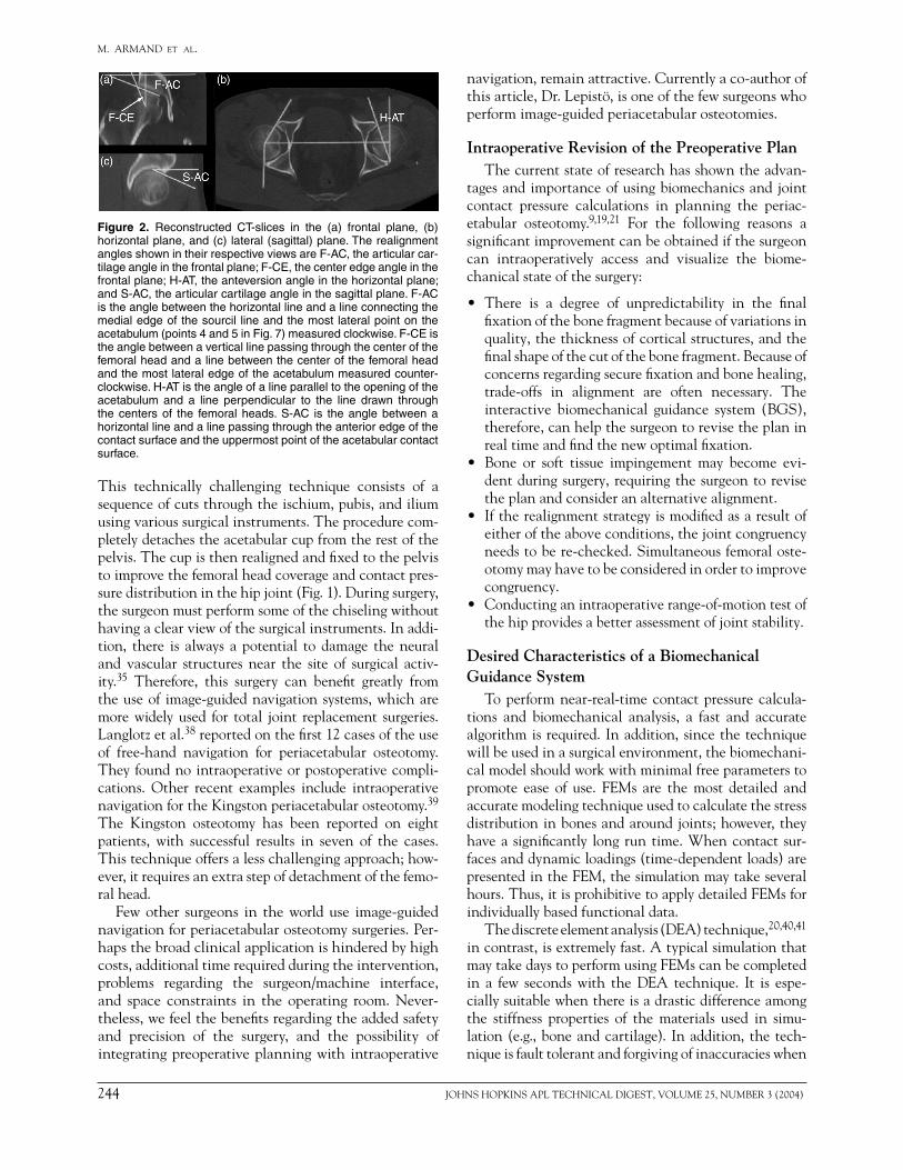
Figure 2. Reconstructed CT-slices in the (a) frontal plane, (b) horizontal plane, and (c) lateral (sagittal) plane. The realignment angles shown in their respective views are F-AC, the articular car-tilage angle in the frontal plane; F-CE, the center edge angle in the frontal plane; H-AT, the anteversion angle in the horizontal plane; and S-AC, the articular cartilage angle in the sagittal plane. F-AC is the angle between the horizontal line and a line connecting the medial edge of the sourcil line and the most lateral point on the acetabulum (points 4 and 5 in Fig. 7) measured clockwise. F-CE is the angle between a vertical line passing through the center of the femoral head and a line between the center of the femoral head and the most lateral edge of the acetabulum measured counter-clockwise. H-AT is the angle of a line parallel to the opening of the acetabulum and a line perpendicular to the line drawn through the centers of the femoral heads. S-AC is the angle between a horizontal line and a line passing through the anterior edge of the contact surface and the uppermost point of the acetabular contact surface.
JOHNS HOPKINS APL TECHNICAL DIGEST, VOLUME 25, NUMBER 3 (2004) 245
COMPUTER-AIDED ORTHOPEDIC SURGERY
defi ning the contact area. Also, in contrast to FEMs, running DEA algorithms requires defi ning very few parameters. Later, we discuss our preliminary results for experimental validation of the DEA technique for approximating the pressure distribution and location of maximum stress in the hip joint.
In the following sections we present an overview of the architecture of image-guided hip osteotomy with the intraoperative BGS and its components. We discuss the algorithms for 3D reconstruction of the acetabular car-tilage and femur for preoperative planning and intraop-erative biomechanical guidance of the surgery. Next, we describe our computer-aided preoperative planning and postoperative results for 12 patients who have under-gone periacetabular hip osteotomy. Finally, we present our experimental validation studies for contact pressure distribution of the hip.
SYSTEM OVERVIEWThe overview of the image-guided system with bio-
Intraoperative Registration In the operating room, an optical tracking camera is
used to detect the coordinates of the anatomical land-marks on the pelvis using infrared markers (attached to the reference screws) and a digitizing probe. The 3D image and the 3D biomechanical model of the pelvis are registered to the pelvis of the patient using anatomical landmarks and surface-matching algorithms. Details of the registration technique are described in the Intraop-erative Navigation section.
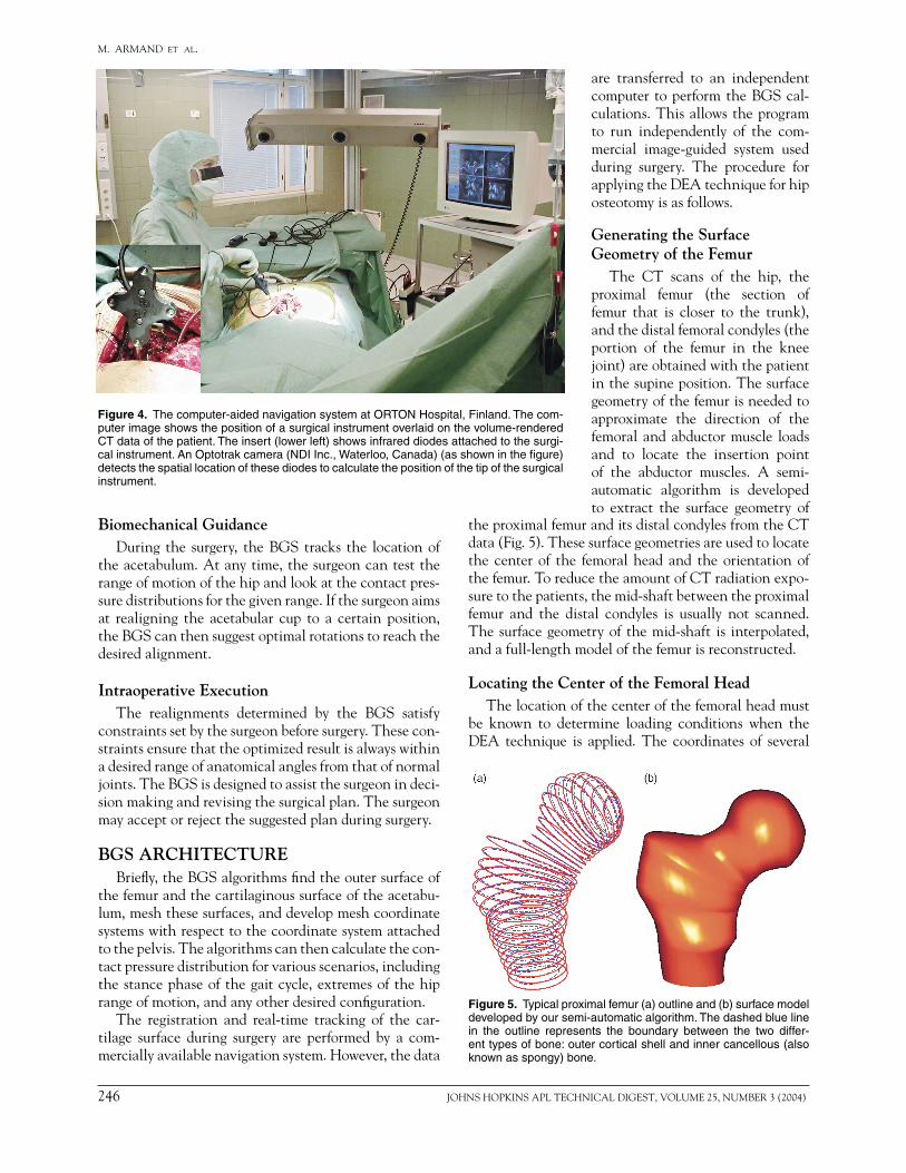
Intraoperative TrackingInfrared diodes are attached to the pelvis to refer-
ence its position. They are also attached to surgical instruments (Fig. 4). During the surgery their loca-tion and trajectory are overlaid on the referenced 3D image of the pelvis to help the surgeon chisel the bone without a clear view. The camera system also tracks the acetabulum after it is detached from the pelvis.
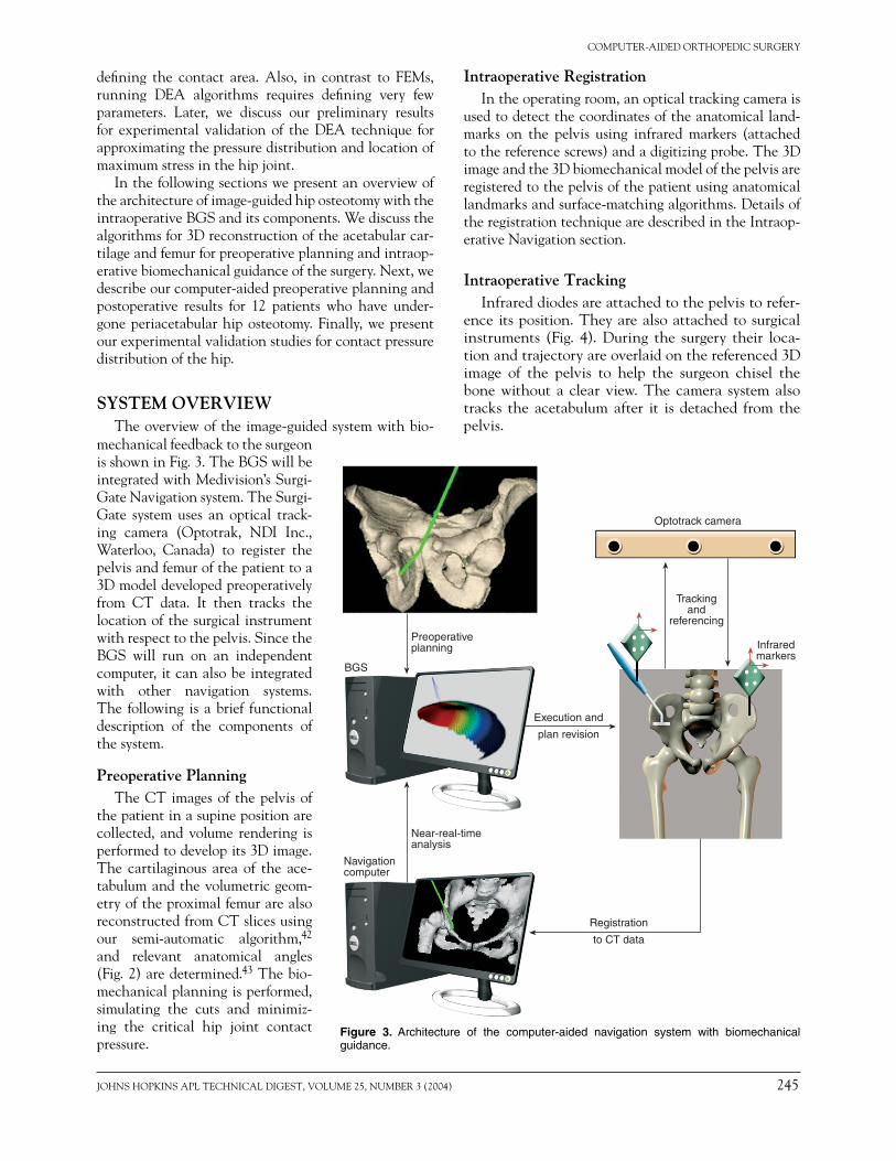
Figure 3. Architecture of the computer-aided navigation system with biomechanical guidance.
mechanical feedback to the surgeon is shown in Fig. 3. The BGS will be integrated with Medivision’s Surgi-Gate Navigation system. The Surgi-Gate system uses an optical track-ing camera (Optotrak, NDI Inc., Waterloo, Canada) to register the pelvis and femur of the patient to a 3D model developed preoperatively from CT data. It then tracks the location of the surgical instrument with respect to the pelvis. Since the BGS will run on an independent computer, it can also be integrated with other navigation systems. The following is a brief functional description of the components of the system.
Preoperative Planning The CT images of the pelvis of
the patient in a supine position are collected, and volume rendering is performed to develop its 3D image. The cartilaginous area of the ace-tabulum and the volumetric geom-etry of the proximal femur are also reconstructed from CT slices using our semi-automatic algorithm,42 and relevant anatomical angles (Fig. 2) are determined.43 The bio-mechanical planning is performed, simulating the cuts and minimiz-ing the critical hip joint contact pressure.
Navigationcomputer
BGS
Preoperativeplanning
Near-real-timeanalysis
Trackingand
referencing
Infraredmarkers
Optotrack camera
Registration
to CT data
Execution and
plan revision
246 JOHNS HOPKINS APL TECHNICAL DIGEST, VOLUME 25, NUMBER 3 (2004)
M. ARMAND ET AL.
Biomechanical GuidanceDuring the surgery, the BGS tracks the location of
the acetabulum. At any time, the surgeon can test the range of motion of the hip and look at the contact pres-sure distributions for the given range. If the surgeon aims at realigning the acetabular cup to a certain position, the BGS can then suggest optimal rotations to reach the desired alignment.
Intraoperative ExecutionThe realignments determined by the BGS satisfy
constraints set by the surgeon before surgery. These con-straints ensure that the optimized result is always within a desired range of anatomical angles from that of normal joints. The BGS is designed to assist the surgeon in deci-sion making and revising the surgical plan. The surgeon may accept or reject the suggested plan during surgery.
BGS ARCHITECTUREBriefl y, the BGS algorithms fi nd the outer surface of
the femur and the cartilaginous surface of the acetabu-lum, mesh these surfaces, and develop mesh coordinate systems with respect to the coordinate system attached to the pelvis. The algorithms can then calculate the con-tact pressure distribution for various scenarios, including the stance phase of the gait cycle, extremes of the hip range of motion, and any other desired confi guration.
The registration and real-time tracking of the car-tilage surface during surgery are performed by a com-mercially available navigation system. However, the data
are transferred to an independent computer to perform the BGS cal-culations. This allows the program to run independently of the com-mercial image-guided system used during surgery. The procedure for applying the DEA technique for hip osteotomy is as follows.
Generating the Surface Geometry of the Femur
The CT scans of the hip, the proximal femur (the section of femur that is closer to the trunk), and the distal femoral condyles (the portion of the femur in the knee joint) are obtained with the patient in the supine position. The surface geometry of the femur is needed to approximate the direction of the femoral and abductor muscle loads and to locate the insertion point of the abductor muscles. A semi-automatic algorithm is developed to extract the surface geometry of
Figure 4. The computer-aided navigation system at ORTON Hospital, Finland. The com-puter image shows the position of a surgical instrument overlaid on the volume-rendered CT data of the patient. The insert (lower left) shows infrared diodes attached to the surgi-cal instrument. An Optotrak camera (NDI Inc., Waterloo, Canada) (as shown in the fi gure) detects the spatial location of these diodes to calculate the position of the tip of the surgical instrument.
the proximal femur and its distal condyles from the CT data (Fig. 5). These surface geometries are used to locate the center of the femoral head and the orientation of the femur. To reduce the amount of CT radiation expo-sure to the patients, the mid-shaft between the proximal femur and the distal condyles is usually not scanned. The surface geometry of the mid-shaft is interpolated, and a full-length model of the femur is reconstructed.
Locating the Center of the Femoral HeadThe location of the center of the femoral head must
be known to determine loading conditions when the DEA technique is applied. The coordinates of several
Figure 5. Typical proximal femur (a) outline and (b) surface model developed by our semi-automatic algorithm. The dashed blue line in the outline represents the boundary between the two differ-ent types of bone: outer cortical shell and inner cancellous (also known as spongy) bone.
JOHNS HOPKINS APL TECHNICAL DIGEST, VOLUME 25, NUMBER 3 (2004) 247
COMPUTER-AIDED ORTHOPEDIC SURGERY
points on the surface of the femoral head are selected. The center of the femoral head is approximated by per-forming an ellipsoidal fi t of the selected points on the surface of the femoral head.
Extracting the Surface Geometry of the Acetabular Cartilage
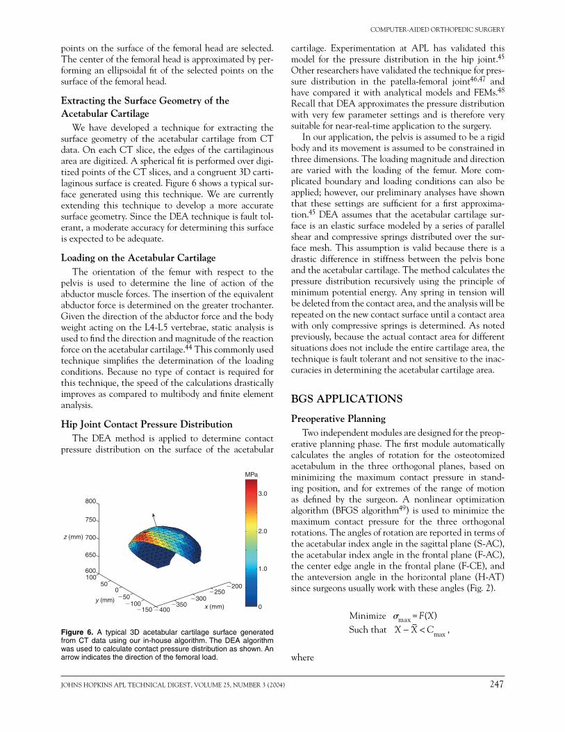
We have developed a technique for extracting the surface geometry of the acetabular cartilage from CT data. On each CT slice, the edges of the cartilaginous area are digitized. A spherical fi t is performed over digi-tized points of the CT slices, and a congruent 3D carti-laginous surface is created. Figure 6 shows a typical sur-face generated using this technique. We are currently extending this technique to develop a more accurate surface geometry. Since the DEA technique is fault tol-erant, a moderate accuracy for determining this surface is expected to be adequate.
Loading on the Acetabular Cartilage The orientation of the femur with respect to the
pelvis is used to determine the line of action of the abductor muscle forces. The insertion of the equivalent abductor force is determined on the greater trochanter. Given the direction of the abductor force and the body weight acting on the L4-L5 vertebrae, static analysis is used to fi nd the direction and magnitude of the reaction force on the acetabular cartilage.44 This commonly used technique simplifi es the determination of the loading conditions. Because no type of contact is required for this technique, the speed of the calculations drastically improves as compared to multibody and fi nite element analysis.
Hip Joint Contact Pressure Distribution The DEA method is applied to determine contact
pressure distribution on the surface of the acetabular
cartilage. Experimentation at APL has validated this model for the pressure distribution in the hip joint.45 Other researchers have validated the technique for pres-sure distribution in the patella-femoral joint46,47 and have compared it with analytical models and FEMs.48 Recall that DEA approximates the pressure distribution with very few parameter settings and is therefore very suitable for near-real-time application to the surgery.
In our application, the pelvis is assumed to be a rigid body and its movement is assumed to be constrained in three dimensions. The loading magnitude and direction are varied with the loading of the femur. More com-plicated boundary and loading conditions can also be applied; however, our preliminary analyses have shown that these settings are suffi cient for a fi rst approxima-tion.45 DEA assumes that the acetabular cartilage sur-face is an elastic surface modeled by a series of parallel shear and compressive springs distributed over the sur-face mesh. This assumption is valid because there is a drastic difference in stiffness between the pelvis bone and the acetabular cartilage. The method calculates the pressure distribution recursively using the principle of minimum potential energy. Any spring in tension will be deleted from the contact area, and the analysis will be repeated on the new contact surface until a contact area with only compressive springs is determined. As noted previously, because the actual contact area for different situations does not include the entire cartilage area, the technique is fault tolerant and not sensitive to the inac-curacies in determining the acetabular cartilage area.
BGS APPLICATIONS
Preoperative Planning Two independent modules are designed for the preop-
erative planning phase. The fi rst module automatically calculates the angles of rotation for the osteotomized acetabulum in the three orthogonal planes, based on minimizing the maximum contact pressure in stand-ing position, and for extremes of the range of motion as defi ned by the surgeon. A nonlinear optimization algorithm (BFGS algorithm49) is used to minimize the maximum contact pressure for the three orthogonal rotations. The angles of rotation are reported in terms of the acetabular index angle in the sagittal plane (S-AC), the acetabular index angle in the frontal plane (F-AC), the center edge angle in the frontal plane (F-CE), and the anteversion angle in the horizontal plane (H-AT) since surgeons usually work with these angles (Fig. 2).
Minimize �max = F(X) Such that X X C− < max ,
where
�200
x (mm)y (mm)
z (mm)
3.0
MPa
2.0
1.0
0�400�150
100600
800
700
�3000
50
�100�50
�250
�350
650
750
Figure 6. A typical 3D acetabular cartilage surface generated from CT data using our in-house algorithm. The DEA algorithm was used to calculate contact pressure distribution as shown. An arrow indicates the direction of the femoral load.
248 JOHNS HOPKINS APL TECHNICAL DIGEST, VOLUME 25, NUMBER 3 (2004)
M. ARMAND ET AL.
�max = the maximum contact pressure in the standing position,
X = the desired vector of three anatomical angles, S-AC, F-AC, and H-AT,
X = the vector of the above three anatomical angles measured in the normal joint of the patient, and
Cmax = the vector of maximum permissible deviation from X as obtained from the literature.
Several initial conditions in the neighborhood of X are used during the optimization to ensure the existence of a unique solution (global minimum). The second module enables the surgeon to select the change of angle in the three orthogonal planes or based on selecting S-AC, F-AC, and H-AT angles.
Intraoperative Navigation During surgery the registration of the pelvis follows
the protocol designed for Medivision’s SurgiGate system as follows. Three or four pairs of points on the bony frag-ment of the pelvis are registered by a digitizing pointer. Next, 12 or 13 points on the surface of the bone near the line of the osteotomy are digitized (bone surface registra-tion). An additional registration step is performed for the BGS: three small screws or pins are attached to the bony fragment of the pelvis that is relocated during the oste-otomy. Before the bone is osteotomized, the coordinates of these screws are digitized using the digitizing pointer. After the osteotomy is performed, at any time during the surgery, the surgeon can digitize the new coordinates of these screws. The new coordinates are the input to the BGS used to calculate the new orientation of the oste-otomized fragment using both Euler angles and the sur-gical reference angles (S-AC, F-CE, F-AC, and H-AT). The BGS then fi nds the contact pressure distribution, the location and magnitude of the maximum contact pressure, and the centroid of contact pressure.
Finally, the BGS performs optimization to determine whether there is any orientation in the neighborhood of the existing orientation that would minimize the maximum contact pressure for the stance phase and the extremes of the range of motion. For the new set point, the surgeon checks the new range of motion, and the calculations are updated.
PRELIMINARY RESULTSThe following describes our preliminary results,
which include (1) the validation of the biomechanical technique as the core of the BGS architecture, and (2) the application of the DEA to preoperative planning. These studies demonstrate the importance of biome-chanical analysis in the successful performance of the periacetabular osteotomy and present original surgical outcome data that can be compared to the results of the application of the BGS architecture.
Signifi cance of Biomechanical Analysis We analyzed the effect of periacetabular osteotomy
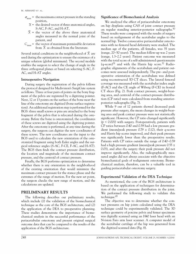
on hip dysplasia using CAS of joint contact pressure on regular standing anterior-posterior radiographs.50 These results were compared with the results of surgery based on realignment of the acetabular angles to the normal hip. Twelve consecutive periacetabular osteoto-mies with no femoral head deformity were studied. The median age of the patients, all females, was 35 years (range, 20−50 years). The median follow-up was 2 years (range, 1.3−2.2 years). Patient outcome was measured with the total score of a self-administered questionnaire (q-score)51 and with the Harris hip score.52 Radio-graphic alignments of the acetabulum and patient out-comes were assessed independently. The pre- and post-operative orientation of the acetabulum was defi ned using reconstructed 3D CT slices. The lateral femoral coverage was measured with the acetabular index angle (F-AC) and the CE angle of Wiberg (F-CE) in frontal CT slices (Fig. 2). Peak contact pressure, weight-bear-ing area, and centroid of the contact-pressure distribu-tion (CP ratio) were calculated from standing anterior-posterior radiographs (Fig. 7).
While 9 out of 12 patients showed decreased peak pressure after surgery, the mean changes in weight-bear-ing area and peak contact pressure were not statistically signifi cant. However, the CP ratio changed signifi cantly (p < 0.001) with surgery. Postoperatively, patients with CP ratios between 0.40 and 0.59 had a low pressure gra-dient (mean/peak pressure 0.79 ± 0.12), their q-scores and Harris hip scores improved, and their peak pressure was signifi cantly lower than the preoperative results. Patients with CP ratios outside the range of 0.40−0.59 had a high pressure gradient (mean/peak pressure 0.55 ± 0.03), and after the surgery their peak pressure did not improve signifi cantly. Also, the radiographically mea-sured angles did not always associate with the objective biomechanical goals of realignment osteotomy. Biome-chanical analysis, therefore, can be a valuable tool in guiding periacetabular osteotomy surgery.
Experimental Validation of the DEA TechniqueAs mentioned, the core of the BGS architecture is
based on the application of techniques for determina-tion of the contact pressure distribution in the joint. We performed the following study to validate this technique.45
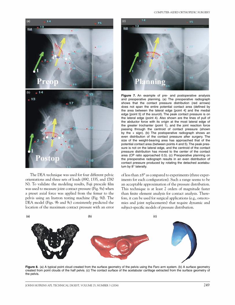
The objective was to determine whether the con-tact pressures on hip joints calculated using the DEA technique could be experimentally validated. The 3D surface geometry of porcine pelvis and femur specimens was digitally scanned using an H40 laser head with an Nvision Faro arm laser scanner. A computer model of the acetabular cartilage of the hip was generated from the digitized scanned data (Fig. 8).
JOHNS HOPKINS APL TECHNICAL DIGEST, VOLUME 25, NUMBER 3 (2004) 249
COMPUTER-AIDED ORTHOPEDIC SURGERY
Figure 7. An example of pre- and postoperative analysis and preoperative planning. (a) The preoperative radiograph shows that the contact pressure distribution (red arrows) does not span the entire potential contact area (defi ned by the area between the lateral edge [point 4] and the medial edge [point 5] of the sourcil). The peak contact pressure is on the lateral edge (point 4). Also shown are the lines of pull of the abductor force with its origin at the most lateral edge of the greater trochanter (point 1), and the joint reaction force passing through the centroid of contact pressure (shown by the + sign). (b) The postoperative radiograph shows an even distribution of the contact pressure after surgery. The size of the weight-bearing area has approached that of the potential contact area (between points 4 and 5). The peak pres-sure is not on the lateral edge, and the centroid of the contact pressure distribution has moved to the center of the contact area (CP ratio approached 0.5). (c) Preoperative planning on the preoperative radiograph results in an even distribution of contact pressure produced by rotating the detached acetabu-lum by 8° laterally.
Figure 8. (a) A typical point cloud created from the surface geometry of the pelvis using the Faro arm system. (b) A surface geometry created from point clouds of the half pelvis. (c) The contact surface of the acetabular cartilage extracted from the surface geometry of the pelvis.
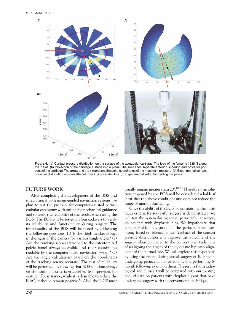
The DEA technique was used for four different pelvic orientations and three sets of loads (890, 1335, and 1780 N). To validate the modeling results, Fuji prescale fi lm was used to measure joint contact pressure (Fig. 9a) when a preset axial force was applied from the femur to the pelvis using an Instron testing machine (Fig. 9d). The DEA model (Figs. 9b and 9c) consistently predicted the location of the maximum contact pressure with an error
of less than ±8° as compared to experiments (three exper-iments for each confi guration). Such a range seems to be an acceptable approximation of the pressure distribution. This technique is at least 2 orders of magnitude faster than fi nite element analysis for contact analysis. There-fore, it can be used for surgical applications (e.g., osteoto-mies and joint replacements) that require dynamic and subject-specifi c models of pressure distribution.
250 JOHNS HOPKINS APL TECHNICAL DIGEST, VOLUME 25, NUMBER 3 (2004)
M. ARMAND ET AL.
FUTURE WORKAfter completing the development of the BGS and
integrating it with image-guided navigation systems, we plan to test the protocol for computer-assisted periac-etabular osteotomy with online biomechanical guidance and to study the reliability of the results when using the BGS. The BGS will be tested on four cadavers to verify its reliability and functionality during surgery. The functionality of the BGS will be tested by addressing the following questions. (1) Is the thigh marker always in the sight of the camera for various thigh angles? (2) Are the tracking screws (attached to the osteotomized pelvic bone) always accessible and their coordinates readable by the computer-aided navigation system? (3) Are the angle calculations based on the coordinates of the tracking screws accurate? The test of reliability will be performed by showing that BGS solutions always satisfy minimum criteria established from previous lit-erature. For instance, while it is desirable to reduce the F-AC, it should remain positive.53 Also, the F-CE must
Figure 9. (a) Contact pressure distribution on the surface of the acetabular cartilage. The load of the femur is 1335 N along the z axis. (b) Projection of the cartilage surface into a plane. The solid lines separate anterior, superior, and posterior por-tions of the cartilage. The arrow and the x represent the polar coordinates of the maximum pressure. (c) Experimental contact pressure distribution on a rosette cut from Fuji prescale fi lms. (d) Experimental setup for loading the pelvis.
usually remain greater than 20°.10,20 Therefore, the solu-tion proposed by the BGS will be considered reliable if it satisfi es the above conditions and does not reduce the range of motion drastically.
Once the ability of the BGS for maintaining the mini-mum criteria for successful surgery is demonstrated, we will test the system during actual periacetabular surgery on patients with dysplastic hips. We hypothesize that computer-aided navigation of the periacetabular oste-otomy based on biomechanical feedback of the contact pressure distribution will improve the outcome of the surgery when compared to the conventional technique of realigning the angles of the dysplastic hip with align-ment of the normal side. We will explore this hypothesis by using the system during actual surgery of 10 patients undergoing periacetabular osteotomy and performing 6-month follow-up exams on them. The results (both radio-logical and clinical) will be compared with our existing pool of data on patients with dysplastic joint that have undergone surgery with the conventional technique.
JOHNS HOPKINS APL TECHNICAL DIGEST, VOLUME 25, NUMBER 3 (2004) 251
COMPUTER-AIDED ORTHOPEDIC SURGERY
REFERENCES 1DiGioia, A. M., Jaramaz, B., and O’Toole, R. V., “An Integrated
Approach to Medical Robotics and Computer Assisted Surgery in Orthopaedics,” in Proc. 1st Int. Symp. on Medical Robotics and Com-puter Assisted Surgery, Pittsburgh, PA, pp. 106−111 (1994).
2Cinquin, P., and Lavellée, S., “IGOR: Image Guided Operating Robot,” Innov. Technol. Biol. Med. [French] 13(4), 374−394 (1992).
3Lavallée, S., Troccaz, J., Sautot, P., Mazier, B., Cinquin, P., et al., “Computer-Assisted Spinal Surgery Using Anatomy-Based Registra-tion,” in Computer-Integrated Surgery, R. H. Taylor et al. (eds.), MIT Press, Cambridge, MA, pp. 425−449 (1996).
4Nolte, L. P., and Ganz, R. (eds.), Computer Assisted Orthopaedic Sur-gery (CAOS), Hogrefe and Huber, Seattle, WA (1999).
5Taylor, R. H., Lavallée, S., Burdea, G. C., and Mosges, R. (eds.), Com-puter-Integrated Surgery, MIT Press, Cambridge, MA (1996).
6Taylor, R. H., Funda, J., Joskowicz, L., Kalvin, A. D., Gomory, S. H., et al., “An Overview of Computer-Integrated Surgery Research at the IBM T. J. Watson Research Center,” IBM J. Res. Dev. 40(2), 163 (Mar 1996).
7Taylor, R. H., “Robotics in Orthopaedic Surgery,” in Computer Assisted Orthopaedic Surgery (CAOS), L. P. Nolte and R. Ganz (eds.), Hogrefe and Huber, Seattle, WA, pp. 35−41 (1999).
8Taylor, R., “Computer-Integrated Surgery: Coupling Information to Action in 21st Century Medicine,” in Proc. HiCare 2000, Dusseldorf, p. 13 (2000).
9Murphy, S. B., Kuewski, K. P., Millis, M. B., Hall, J. E., Sheldon, R. S., and Chandler, H. P., “The Planning of Orthopaedic Reconstructive Surgery Using Computer-Aided Simulation and Design,” Comput. Med. Imag. Graph. 12(1), 33−45 (1988).
10Millis, M. B., and Murphy, M. S., “Use of Computed Tomographic Reconstruction in Planning Osteotomies of the Hip,” Clin. Orthop. 274, 154−159 (1992).
11Langlotz, F., Stucki, S. M., Bachler, R., Scheer, C., Ganz, R., et al., “The First Twelve Cases of Computer Assisted Periacetabular Oste-otomy,” Comput. Aided Surg. 7(3), 317−326 (1997).
12Mayman, D. J., Rudan, R. J., Yach, J., and Ellis, R., “The Kingston Periacetabular Osteotomy Utilizing Computer Enhancement: A New Technique,” Comput. Aided Surg. 7(3), 179−186 (2002).
13Bargar, W., DiGioia, A., Turner, R., Taylor, J., McCarthy, J., et al., “Robodoc Multi-Center Trial: An Interim Report,” in Proc. 2nd Int. Symp. on Medical Robotics and Computer Assisted Surgery, Baltimore, MD, pp. 208−214, Pittsburgh, PA (1995).
14Bauer, A., Börner, M., and Lahmer, A., “Robodoc - Animal Evalua-tion and Clinical Evaluation,” in Proc. First Joint Conf. of CVRMed and MRCAS, J. Troccas et al. (eds.), Grenoble, France, pp. 561–564 (1997).
15Wiesel, U., Lahmer, A. L., Börner, M., and Skibbe, H., “ROBODOC(R) at BGU Frankfurt—Experiences with the Pinless System,” in Proc. Computer Assisted Orthopaedic Surgery (CAOS)/USA, Pittsburgh, PA (1999).
16Lahmer, A. L., Wiesel, U., Tenbusch, M., and Börner, M., “Total Knee Replacement Using the Robodoc System,” in Proc. First Ann. Mtg. of CAOS Int., Davos, Switzerland (2001).
17Mai, S., and Siebert, W., “Planning and Technique Using the Robot-System ‘CASPAR’ for TKR,” in Proc. CAOS USA 2001, CAOS International, Pittsburgh, PA (2001).
18DiGioia, A. M., Jarmaz, J. B., and Colgan, B. D., “Computer Assisted Orthopaedic Surgery: Image Guided and Robotic Assistive Technol-ogy,” Clin. Orthop. 354, 8−16 (1998).
19Chao, E. Y. C., Armand, M., Lepistö, J., Genda, E., Nakamura, M., et al., “Computer-Aided Hip Osteotomy Preoperative Planning,” in Proc. Orthopaedic Res. Soc. Mtg., Orlando, FL (2000).
20Genda, E., Konishi, K. N., Hasegawa, N., and Mirua, T., “A Computer Simulation Study of Normal and Abnormal Hip Joint Contact Pres-sures,” Arch. Orthop. Trauma Surg. 364, 114−202 (1995).
21Hipp, J. A., Sugano, S. N., Millis, M. B., and Murphy, S. B., “Planning Acetabular Redirection Osteotomies Based on Joint Contact Pres-sures,” Clin. Orthop. 364, 134−143 (1999).
22Merloz, P., Tonetti, J., Eid, A., Faure, C., Pittet, L., et al., “Computer-Assisted Versus Manual Spine Surgery: Clinical Report,” in Proc. First Joint Conf. of CVRMed and MRCAS, Grenoble, France, pp. 541−544 (1997).
23Nolte, L. P., Zamorano, L. J., Jiang, Z., Wang, Q., Langlotz, F., et al., “A Novel Approach to Computer Assisted Spine Surgery,” in Proc.
First Int. Symp. on Medical Robotics and Computer Assisted Surgery, MRCAS, Pittsburgh, PA, pp. 323−328 (1994).
24vanHellenMondt, G., deKleuver, M., and Pavlov. P., “Computer Assisted Pelvic Osteotomies; Clinical Experience in 25 Cases,” in Proc. First Ann. Mtg. of CAOS Int., Davos, Switzerland (2001).
25Joskowicz, L., Milgrom, C., Simkin, A., Tockus, L., and Yaniv, Z., “FRACAS: A System for Computer-Aided Image-Guided Long Bone Fracture Surgery,” J. Comput. Assist. Surg. 3(6), 271−288 (1999).
26DiGioia, A. M., Simon, D. A., Jaramaz, B., Colgan, B. D., Black-well, M., et al., “HipNav: Pre-operative Planning and Intra-operative Navigational Guidance for Acetabular Implant Placement in Total Hip Replacement Surgery,” in Computer Assisted Orthopedic Surgery (CAOS), L. P. Nolte and R. Ganz (eds.), Hofgrefe and Huber, Seattle, WA, pp. 230–251 (1999).
27Kunz, M., Langlotz, F., Strauss, J. M., Ruther, W., and Nolte, L. P., “Development and Verifi cation of a Non-CT Based Total Knee Arthroplasty System for the LCS Prosthesis,” in Proc. First Ann. Mtg. of CAOS Int., Davos, Switzerland (2001).
28Kunz, M., Strauss, M., Langlotz, F., Deuretzbacher, G., Ruther, W., et al., “A Non-CT Based Total Knee Arthroplasty System Featur-ing Complete Soft-Tissue Balancing,” in Proc. Medical Image Com-puting and Computer-Assisted Intervention—MICCAI 2001, Springer, Utrecht, The Netherlands, pp. 409−415 (2001).
29Wiberg, G., “Studies on Dysplastic Acetabula and Congenital Sublux-ation of the Hip Joint with Special Reference to the Complication of Osteoarthritis,” Acta Chir. Scand. 83(suppl.), 58 (1939).
30Cooperman, D. R., Wallensten, R., and Stulberg, S. D., “Acetabular Dysplasia in the Adult,” Clin. Orthop. 175, 79−85 (May 1983).
31Matta, J. M., Stover, M. D., and Siebenrock, K., “Periacetabular Oste-otomy Through the Smith-Peterson Approach,” Clin. Orthop. Rel. Res. 363, 2−32 (1999).
32Anwar, M. M., Sugano, N., Matsui, M., Takaoka, K., and Ono, K., “Dome Osteotomy of the Pelvis for Orthoarthritis Secondary to Hip Dysplasia. An over Five-Year Follow-up Study,” J. Bone Joint Surg. 75B, 222−227 (1993).
33Eppright, R. H., “Dual Osteotomy of the Acetabulum in the Treat-ment of Dysplasia of the Hip,” J. Bone Joint Surg. 58A, 726 (1976).
34Tönnis, D., Behrens, K., and Tscharani, F., “A Modifi ed Technique of the Triple Pelvic Osteotomy,” J. Pediatr. Orthop. 1, 241–249 (1981).
35Ganz, R., Klaue, K., Vinh, T. S., and Mast, J. W., “A New Periac-etabular Osteotomy for the Treatment of Hip Dysplasias: Technique and Preliminary Results,” Clin. Orthop. 232, 26−36 (1988).
36Millis, M. B., Murphy, S. B., and Poss, R., “Osteotomies About the Hip for Prevention and Treatment of Osteoarthritis,” J. Bone Joint Surg. 77A, 626−647 (1995).
37Reichel, H., and Hein, W., “Dega Acetabuloplasty Combined with Intertrochanteric Osteotomies: Long Term Results,” Clin. Orthop. 323, 234−242 (1996).
38Langlotz, F., Stucki, M., Bachler, R., Scheer, C., Ganz, R., et al., “The First Twelve Cases of Computer Assisted Periacetabular Osteotomy,” Comput. Aided Surg. 2(6), 317−26 (1997).
39Mayman, D. J., Rudan, J., Yach, J., and Ellis, R., “The Kingston Peri-acetabular Osteotomy Utilizing Computer Enhancement: A New Technique,” Comput. Aided Surg. 7(3), 179−186 (2002).
40Kawai, T., and Toi, Y., “A Discrete Method of Limit Analysis with Simplifi ed Elements,” in Selected Papers of Emeritus Professor Dr. Tada-hiko Kawai, Japan (1986).
41An, K. N., Himeno, S., Tsumura, T., and Chao, E. Y. C., “Pressure Distribution on Articular Surfaces: Application of Joint Stability Evaluation,” J. Biomech. 23(10), 1013–1020 (1990).
42Armand, M., Beck, T. J., Boyle, M., Oden, M. Z., Voo, L., and Shapiro, J., “A Semi-automatic Technique for Generating a Parametric Finite Element Model of the Femur from Imaging Modalities,”in Proc. ASME Summer Bioengineering Conf., Key Biscane, FL, p. 29 (Jun 2003).
43Lepistö, J., Tallroth, K., and Alho, A., “Three-Dimensional Measures of Acetabulum in Periacetabular Osteotomy,” in Trans. Orthopaedic Res. Soc. 44th Ann. Mtg. (1998).
44Ninomiya, S., Tagawa, H., Miyanaga, Y., and Seki, N., “The Relation-ship Between the Position of the Artifi cial Joint and Resultant Force Acting on the Femoral Head,” J. Jpn. Orthop. Assoc. 50(1), 12−20 (1975).
45Armand, M., Merkle, A., Sukal, T., and Kleinberger, M., “Experimen-tal Evaluation of a Model of Contact Pressure Distribution in the Hip
252 JOHNS HOPKINS APL TECHNICAL DIGEST, VOLUME 25, NUMBER 3 (2004)
M. ARMAND ET AL.
Joint,” in Proc. 4th World Congress on Biomechanics, Calgary, Alberta (Aug 2002).
46Elias, J., Cosgarea, A., Armand, M., and Chao, E., “Computational Quantifi cation of the Infl uence of the Q-Angle on the Patellofemoral Contact Pressure Distribution,” in Proc. Am. Soc. Biomechanics, San Diego, CA (Jun 2001).
47Elias, J. J., Wilson, D. R., Adamson, R., and Cosgarea, A. J., “Evaluation of a Computational Model Used to Predict the Patellofemoral Contact Pressure Distribution,” J. Biomech. 37(3), 295−302 (Mar 2004).
48Li, G., Sakamoto, M., and Chao, E. Y. S., “A Comparison of Differ-ent Methods in Predicting Static Pressure Distribution in Articulating Joints,” J. Biomech. 30(6), 635–638 (1997).
49Gill, P. E., Murray, W., and Wright, M. H., Chaps. 7 and 8, in Numerical Linear Algebra and Optimization, Vol. 1, Addison-Wesley, Redwood City, CA (1991).
50Lepistö, J., Armand, M., Elias, J., and Chao, E. Y. C., “Outcomes of Periacetabular Osteotomy – Joint Contact Pressure Calculation Using Standing AP Radiographs: 12 Patients Followed for an Average of 2
Years,” Acta Orthop. Scand., in press (2004).51Johanson, N. A., Charlson, M. E., Szatrowski, T. P., and Ranawat,
C. S., “A Self-Administered Hip-Rating Questionnaire for the Assess-ment of Outcome After Total Hip Replacement,” J. Bone Joint Surg. 74-A, 587−597 (1992).
52Harris, W. H., “Traumatic Arthritis of the Hip after Dislocation and Acetabular Fractures: Treatment by Mold Arthroplasty,” J. Bone Joint Surg. 51A, 737−755 (1969).
53Siebenrock, K. A., Schöll, E., Lottenbach, M., and Ganz, R., “Bernese Periacetabular Osteotomy,” Clin. Orthop. 363, 9−20 (1999).
ACKNOWLEDGMENTS: This work is supported by grant number R21 EB002881-01 from the National Institute of Biomedical Imaging and Bioengi-neering (NIH/NIBIB). We dedicate this work to the memory of Dr. James Wenz, Chair of Johns Hopkins Orthopaedic Surgery, Bayview Center. Dr. Wenz passed away in a tragic car accident on 15 January 2004. He was a co-investigator on this grant and provided clinical expertise in the development and initial execution of the research plan.
THE AUTHORS
James Wenz
Russell H. Taylor
Xiaofeng Liu
Kaj Tallroth
Andrew C. Merkle
Mehran Armand
Jyri V. S. Lepistö
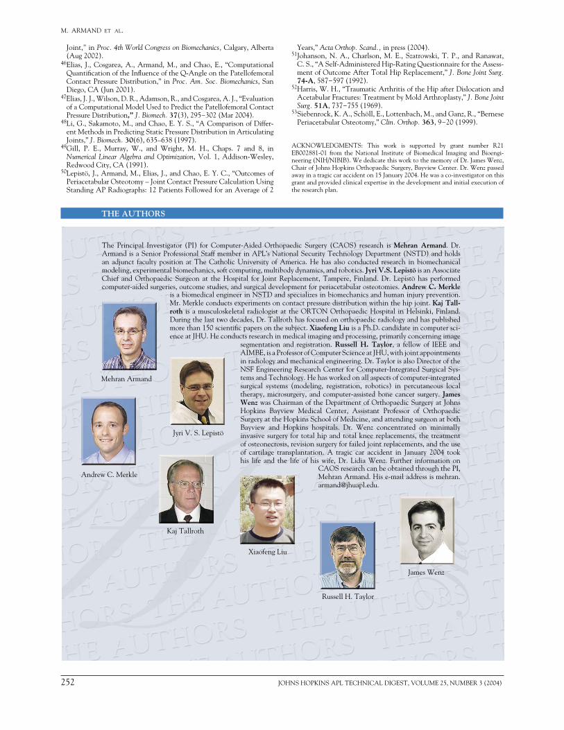
The Principal Investigator (PI) for Computer-Aided Orthopaedic Surgery (CAOS) research is Mehran Armand. Dr. Armand is a Senior Professional Staff member in APL’s National Security Technology Department (NSTD) and holds an adjunct faculty position at The Catholic University of America. He has also conducted research in biomechanical modeling, experimental biomechanics, soft computing, multibody dynamics, and robotics. Jyri V.S. Lepistö is an Associate Chief and Orthopaedic Surgeon at the Hospital for Joint Replacement, Tampere, Finland. Dr. Lepistö has performed computer-aided surgeries, outcome studies, and surgical development for periacetabular osteotomies. Andrew C. Merkle
is a biomedical engineer in NSTD and specializes in biomechanics and human injury prevention. Mr. Merkle conducts experiments on contact pressure distribution within the hip joint. Kaj Tall-roth is a musculoskeletal radiologist at the ORTON Orthopaedic Hospital in Helsinki, Finland. During the last two decades, Dr. Tallroth has focused on orthopaedic radiology and has published more than 150 scientifi c papers on the subject. Xiaofeng Liu is a Ph.D. candidate in computer sci-ence at JHU. He conducts research in medical imaging and processing, primarily concerning image
segmentation and registration. Russell H. Taylor, a fellow of IEEE and AIMBE, is a Professor of Computer Science at JHU, with joint appointments in radiology and mechanical engineering. Dr. Taylor is also Director of the NSF Engineering Research Center for Computer-Integrated Surgical Sys-tems and Technology. He has worked on all aspects of computer-integrated surgical systems (modeling, registration, robotics) in percutaneous local therapy, microsurgery, and computer-assisted bone cancer surgery. James Wenz was Chairman of the Department of Orthopaedic Surgery at Johns Hopkins Bayview Medical Center, Assistant Professor of Orthopaedic Surgery at the Hopkins School of Medicine, and attending surgeon at both Bayview and Hopkins hospitals. Dr. Wenz concentrated on minimally invasive surgery for total hip and total knee replacements, the treatment of osteonecrosis, revision surgery for failed joint replacements, and the use of cartilage transplantation. A tragic car accident in January 2004 took his life and the life of his wife, Dr. Lidia Wenz. Further information on
CAOS research can be obtained through the PI, Mehran Armand. His e-mail address is [email protected].


![[Print] - eMedicine Orthopedic Surgery](https://img.pdfslide.us/doc/110x75/5514008a4a7959df028b4dd8/print-emedicine-orthopedic-surgery.jpg)