Embed Size (px)
Citation preview

Computer Aided Design and Manufacturing

2.1 INTRODUCTION2.1 INTRODUCTION2.2 CONVENTIONAL APPROACH TO 2.2 CONVENTIONAL APPROACH TO DESIGNDESIGN 2.3 DESCRIPTION OF THE DESIGN 2.3 DESCRIPTION OF THE DESIGN PROCESSPROCESS
1.1. Problem definitionProblem definition
2.2. ConceptualizationConceptualization
3.3. SynthesisSynthesis
4.4. AnalysisAnalysis
5. Manufacturing5. Manufacturing

The steps in design

2.3.1 Problem Definition
The problem definition should include the following: The problem definition should include the following:
(1) A statement of objectives and goals to be achieved
(2) A definition of constraints imposed on the design
(3) Criteria for evaluating the design
A well-defined problem is the key to a successful A well-defined problem is the key to a successful design solution. The design process involves many design solution. The design process involves many stages requiring careful thinking; the problem stages requiring careful thinking; the problem definition helps everyone focus on the objectives of definition helps everyone focus on the objectives of the problem and the things that must be the problem and the things that must be accomplished.accomplished.

Conceptualization is the process whereby a preliminary design satisfying the problem definition is formulated. This brings into play the engineer’s knowledge, ingenuity, and experience.
2.3.2 Conceptualization
2.3.3 Synthesis
This is one of the most challenging tasks an engineer faces. At this stage, the information required for the proposed conceptualization is organized and a plan is devised for achieving that design. To achieve a viable synthesis decision, all the elements affecting the design, including product configuration, cost, and labor, must be considered.
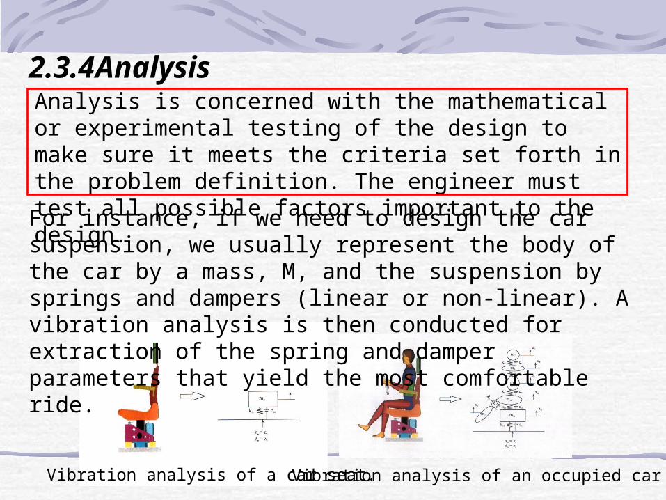
2.3.4 Analysis Analysis is concerned with the mathematical or experimental testing of the design to make sure it meets the criteria set forth in the problem definition. The engineer must test all possible factors important to the design.
Vibration analysis of an occupied car seat Vibration analysis of a car seat.
For instance, if we need to design the car suspension, we usually represent the body of the car by a mass, M, and the suspension by springs and dampers (linear or non-linear). A vibration analysis is then conducted for extraction of the spring and damper parameters that yield the most comfortable ride.

Examples of structural testing
Experimentation in analysis is another critical step in design.
For instance, one might use a lumped mass model representing a car and analyze its behavior with different vibration stimulus or conduct a modal analysis experiment in which a real automobile is tested in the laboratory making use of shakers, transducers, and Fourier analyses.

2.3.1 Problem Definition The assignments, to design a prosthetic leg or arm or an automatic sorting mechanism, serves as the “identification of a need.” The purpose of the conveyer mechanism is to separate defective parts from those that meet the products’ specs. In the case of the prosthetics, the goal of the examples given here is to achieve a design that would allow all the activities that would be possible with real limbs.
Example: ENGINEERING DESIGN PROCESS

2.3.2 Conceptualization
Defining the range of human motion aids the engineer in conceptualizing possible design
Configuration of the components and the choice of materials begins at this stage.

The complex movements of the foot are broken down into a group of simple movements
The mental model begins to take shape at the conceptualization stage.

2.3.3 Synthesis
Assemble view

2.3.4 Analysis
The engineer would determine (either mathematically or through testing) whether the goals set forth in the problem definition step had been reached. If they had, the project would proceed toward a final design and manufacture. If those goals were not reached satisfactorily the engineer would return to the early stages of the process either to modify the problem definition or fine-tune the conceptualization facet of the design process.

2.4 COMPUTER-AIDED DESIGN
Characteristics of CAD

Interaction with various sources of information

2.4.1 Drafting and Design2.4.2 Wireframe Modeling
A Wireframe model.
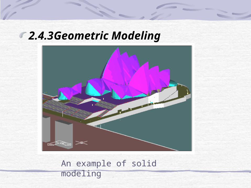
2.4.3 Geometric Modeling
An example of solid modeling

2.5 PARAMETRIC AND VARIATIONAL DESIGNS
2.5.1 Parametric Design Systems In a parametric design, the engineer selects a set of geometric constraints that can be applied for creating the geometry of the component. The geometric elements include lines, arcs, circles, and splines. A set of engineering equations can also be used to define the dimensions of the component. This simple concept of a parametric system can be explained using the following illustrations.
Parametric design of a block

Geometric Constraints1.Solve P1 (origin)2.Solve L1 (horizontal line from origin)3.Solve P2 (known distance on line from P1)4.Solve L2 (vertical line at 90º from P2)5.Solve P2 (known distance on line)6.Solve L3 (horizontal line at -90º from P3)7.Solve P4 (known distance on line from P3)8.Solve L4 (vertical line from P4 at -90º)9.Solve P5 (point at distance from P1 at 45º)10.Solve arc (known radius, start, and endpoint)
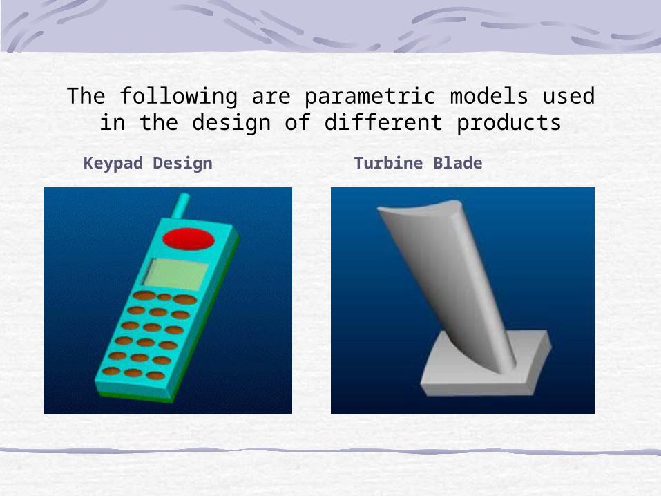
The following are parametric models used in the design of different products
Keypad Design Turbine Blade

Belt Drive Design

2.5.2 Variational Design Systems Unlike the parametric approach, a variational system is able to determine the positions of geometric elements and constraints. In addition, it is structured to handle the coupling between parameters in the geometric con straints and the engineering equations. The variational design concept helps the en gineer evaluate the design of a component in depth instead of considering only the geometric aspects to satisfy the design relationships.

RCDgear vR =⋅ω
Parametric design

222
BB xyAB +=
222
BCBC xyBC +=
222
DCDC xyDC +=
0=++ CDBCB yyy
ADxxx CDBCB =++
The velocity of point B is:
The velocity of the point C is:
ABABAB rvv ×+= ω
DCCDDC rvv ×+= ω
B C
DA

BCBCBC rvv ×+= ω
the velocity is expressed in terms of the velocity of B
jxiyjxiyjxiy BCBCBCBCABBABBCDDCCDDC ωωωωωω +−−=−
( ) 0,,,,, =BCBDCBCABCD yyyf ωωω
( ) 0,,,,, =BCBDCBCABCD xxxg ωωω
222
BB xyAB +=222
BCBC xyBC +=
222
DCDC xyDC +=
0=++ CDBCB yyy
ADxxx CDBCB =++Given that

Airship Design
⎟⎟
⎠
⎞
⎜⎜
⎝
⎛ −
−+=
⋅⋅=
−
c
ac
ac
acaA
caV
221
22
22
2
sin2
2
3
4
ππ
π
( )1,0∈
⋅=
q
aqc
Free body diagram of airship.
a
Ec
L+S+G

From the equilibrium conditions we have
GSLE
F
++=↓
=∑ 0
The density of the airship gas g the density of the atmosphere a the area density of the shell confining the dirigible gas . Therefore we define the corresponding forces:
€
E =V ⋅ρ ag
S =σ ⋅A
G =V ⋅ρ gg
( ) ( ) ( ) ag qaVqaALqaV ρσρ ⋅+⋅+=⋅ ,,,
( ) 0,, =Lqaf

Load necessary for the airship.

Pendulum Pendulum Design:
Movement of Pendulum
0)sin( =⋅+ θθ MglI &&
0=+ θθ MglI &&
I
Mgl=2ω
βα
βα
eb
ea
I
ebeaM
44
2
1
2
1
44
22
−=
−=

22
33
2
1
2
12
sin2
cos3
2
2sin
2cos
3
2
ba
baX
αα
ββαα
+
⎟⎠
⎞⎜⎝
⎛⎟⎠
⎞⎜⎝
⎛+⎟⎠
⎞⎜⎝
⎛⎟⎠
⎞⎜⎝
⎛
=
22
2323
2
1
2
12
sin3
2
2sin
3
2
ba
ba
Yαα
βα
+
⎟⎠
⎞⎜⎝
⎛+⎟⎠
⎞⎜⎝
⎛
=
22 YXl +=
αβ << ab
( )( )1,0
1,0
∈
∈
⋅=
⋅=
q
p
aqb
p αβ
( )qpafI
Mgl,,,αω ==
057.29581
1
==
=
Rad
a
α
( )qpfI
Mgl,==ω
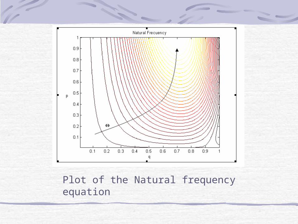
Plot of the Natural frequency equation

Design model to be optimized
Optimized design

2.6 ENGINEERING ANALYSIS AND CAD
Process of engineering analysis in design
Interfacing analysis functions with CAD

2.6.1 Analytical Methods
Finite-Element Analysis.
Kinematics and Synthesis
Static Analysis and Dynamic Analysis.

2.6.2 Experimental Testing EXAMPLE : USING CAD IN STEEL FRAME DESIGN
Steps followed in the design process A CAD flowchart

Terms used in crane construction (courtesy SDRC, Milford, Ohio)
Force and stress diagrams, deforma- tion plot (courtesy SDRC, Milford, Ohio)

2.7 COMPUTER-AIDED ENGINEERING (CAE)
CAE structure as described in reference

The new CAE approach attempts to integrate and automate various engineering functions in the entire product development process:
1. Design2. Analysis3. Testing4. Drafting5. Documentation6. Project Management7. Data Management8. Process Planning9. Tool Design10. Numerical control11. Quality assurance

2.8 INTEGRATED DATABASE MANAGEMENT SYSTEMS IN
CAE
Database management system as described in reference
2.9 CAE PRODUCT DEVELOPMENT 2.10 CAE IMPLEMENTATION
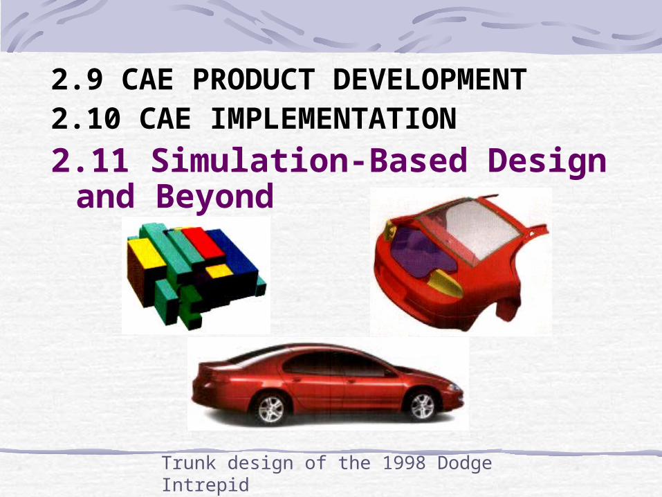
2.11 Simulation-Based Design and Beyond
Trunk design of the 1998 Dodge Intrepid

ISE allowed coordination of as many as 238 design & build teams working on the Boeing 777 simultaneously.
ISE facilitates simulation of entire space missions

With ISE, engineering teams will enjoy unprecedented freedom at every stage of a system’s design.