Embed Size (px)
Citation preview

Computer-Aided Design, Analysis and Load Rating of Precast-PrestressedSpliced Girder Bridges
Western Bridge Engineers’ SeminarReno, NV September 2015
Lynn PetersonSecretary of Transportation
Richard Brice, PESoftware Applications Engineer

Outline
• LRFD Requirements for Spliced Girder Bridges• Overview of Spliced Girder Analysis• Computer Aided Design, Analysis, and Load Rating

Design, Analysis, and Rating of Spliced Girder Bridges
• Basic requirements of conventional precast-prestressed girder bridges – Service stress limitations, ultimate strength
requirements, etc.• LRFD 5.14.1.3 – Spliced Precast Girders
– Additional requirements for contract documents – Additional service stress limitations– Additional analysis requirements

LRFD Requirement for Time-Step Analysis
LRFD 5.9.5.4.1For segmental construction and post-tensioned spliced precast girders, other than during preliminary design, prestress losses shall be determined by the time-step method... including consideration of the time-dependent construction stages and schedule shown in the contract documents.
For components with combined pretensioning and post-tensioning, and where post-tensioning is applied in more that one stage, the effects of subsequent prestressing on the creep loss of previous prestressing shall be considered.
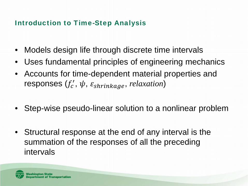
Introduction to Time-Step Analysis
• Models design life through discrete time intervals• Uses fundamental principles of engineering mechanics• Accounts for time-dependent material properties and
responses (𝑓𝑓𝑐𝑐′, 𝜓𝜓, 𝜀𝜀𝑠𝑠𝑠𝑟𝑟𝑟𝑟𝑟𝑟𝑟𝑟𝑟𝑟𝑟𝑟𝑟𝑟, relaxation)
• Step-wise pseudo-linear solution to a nonlinear problem
• Structural response at the end of any interval is the summation of the responses of all the preceding intervals

Challenge of Time-Step Analysis
• Sheer quantity of computations that must be performed– Deformations are computed at many locations– Deformations are computed in every piece of the spliced girder– Deformations are computed for the design life of the structure– Transformed section properties change with time and location
• Non-prismatic segments (haunches, varying tendon locations)• 𝐸𝐸𝑐𝑐 and thus the modular ratios vary with time
– Loading conditions change with time• Staged application of superimposed loads• Multi-staged post-tensioning
– Statical structural system changes with time• Composite closure joints• Composite deck• Temporary support removal

Composition of Spliced Girders
• Precast concrete segments
• CIP concrete closure joints and deck
• Prestressing Strands and Tendons
• Non-prestressedreinforcement

Time Variation of Material Properties
• Three distinct materials• Concrete
– Strength (𝑓𝑓𝑐𝑐′) and stiffness (𝐸𝐸𝑐𝑐) vary with time– Creep rate varies with time and time of loading– Shrinkage rate varies with time
• Prestressing steel– Relaxation rate varies with time and loading
• Non-prestressed Reinforcement– Constant with time. Obeys Hooke’s Law

Timeline Modeling
• Modeled as a sequence of discrete intervals– Begins when segments are constructed– Ends at conclusion of design life
• Interval duration is based on changes in loading and the statical structural system
• Intervals are sub-divided to capture time-dependent material responses immediately following a change in forces

Typical Timeline
Construction Event Day of Occurrence
Construct Segments 0Erect Segments 28Cast Closure Joints and Deck 35Install tendons 42Install traffic barrier 60Open to traffic 70

Incremental Deformations
• Time-step analysis is simply computing incremental deformations during each interval
• Axial strain and curvature– Computed for every part of the girder– Caused by
• externally applied loads• change in statical structural system• creep and shrinkage of concrete• relaxation of prestressing strands and tendons

Computing Incremental Deformations
∆𝜀𝜀𝑐𝑐 𝑖𝑖𝑟𝑟 , 𝑖𝑖𝑏𝑏 =∆𝑃𝑃𝑐𝑐 𝑖𝑖𝑚𝑚𝐴𝐴𝑐𝑐𝐸𝐸𝑐𝑐 𝑖𝑖𝑚𝑚
1 + 𝜓𝜓 𝑖𝑖𝑟𝑟 , 𝑖𝑖𝑚𝑚 + �𝑗𝑗=1
𝑟𝑟−1∆𝑃𝑃𝑐𝑐 𝑗𝑗𝑚𝑚𝐴𝐴𝑐𝑐𝐸𝐸𝑐𝑐 𝑗𝑗𝑚𝑚
𝜓𝜓 𝑖𝑖𝑟𝑟 , 𝑗𝑗𝑚𝑚 − 𝜓𝜓 𝑖𝑖𝑏𝑏, 𝑗𝑗𝑚𝑚 + ∆𝜀𝜀𝑠𝑠𝑠 𝑖𝑖𝑟𝑟 , 𝑖𝑖𝑏𝑏
∆𝜑𝜑𝑐𝑐 𝑖𝑖𝑟𝑟 , 𝑖𝑖𝑏𝑏 =∆𝑀𝑀𝑐𝑐 𝑗𝑗𝑚𝑚𝐼𝐼𝑐𝑐𝐸𝐸𝑐𝑐 𝑗𝑗𝑚𝑚
1 + 𝜓𝜓 𝑖𝑖𝑟𝑟 , 𝑖𝑖𝑚𝑚 + �𝑗𝑗=1
𝑟𝑟−1∆𝑀𝑀𝑐𝑐 𝑗𝑗𝑚𝑚𝐼𝐼𝑐𝑐𝐸𝐸𝑐𝑐 𝑗𝑗𝑚𝑚
𝜓𝜓 𝑖𝑖𝑟𝑟 , 𝑗𝑗𝑚𝑚 − 𝜓𝜓 𝑖𝑖𝑟𝑟 , 𝑗𝑗𝑚𝑚
∆𝜀𝜀𝑝𝑝𝑠𝑠 𝑖𝑖𝑟𝑟 , 𝑖𝑖𝑏𝑏 = ∆𝑃𝑃𝑝𝑝𝑝𝑝 𝑟𝑟𝑚𝑚𝐴𝐴𝑝𝑝𝑝𝑝𝐸𝐸𝑝𝑝𝑝𝑝
+ −∆𝑓𝑓𝑟𝑟 𝑟𝑟𝑒𝑒,𝑟𝑟𝑏𝑏𝐸𝐸𝑝𝑝𝑝𝑝
∆𝜀𝜀𝑟𝑟𝑠𝑠 𝑖𝑖𝑟𝑟 , 𝑖𝑖𝑏𝑏 = ∆𝑃𝑃𝑛𝑛𝑝𝑝(𝑟𝑟𝑚𝑚)𝐴𝐴𝑛𝑛𝑝𝑝𝐸𝐸𝑛𝑛𝑝𝑝
∆𝑃𝑃𝑟𝑟 = ∆𝑃𝑃𝐴𝐴𝑡𝑡𝑟𝑟𝐸𝐸𝑡𝑡𝑟𝑟
+ ∆𝑀𝑀 𝑌𝑌𝑡𝑡𝑟𝑟−𝑌𝑌𝑘𝑘𝐼𝐼𝑡𝑡𝑟𝑟𝐸𝐸𝑡𝑡𝑟𝑟
𝐴𝐴𝑟𝑟𝐸𝐸𝑟𝑟, ∆𝑀𝑀𝑟𝑟 = ∆𝑀𝑀 𝐼𝐼𝑘𝑘𝐸𝐸𝑘𝑘𝐼𝐼𝑡𝑡𝑟𝑟𝐸𝐸𝑡𝑡𝑟𝑟
�𝑃𝑃𝑟𝑟 = −𝐸𝐸𝑟𝑟𝐴𝐴𝑟𝑟𝜀𝜀𝑟𝑟, �𝑀𝑀𝑟𝑟 = −𝐸𝐸𝑟𝑟𝐼𝐼𝑟𝑟𝜑𝜑𝑟𝑟�𝑃𝑃 = ∑𝑟𝑟=1𝑟𝑟 �𝑃𝑃𝑟𝑟, �𝑀𝑀 = ∑𝑟𝑟=1𝑟𝑟 �𝑀𝑀𝑟𝑟 + �𝑃𝑃𝑟𝑟 𝑌𝑌𝑡𝑡𝑟𝑟 − 𝑌𝑌𝑟𝑟̅𝜀𝜀 =
�𝑃𝑃𝐸𝐸𝑡𝑡𝑟𝑟𝐴𝐴𝑡𝑡𝑟𝑟
, �𝜑𝜑 =�𝑀𝑀
𝐸𝐸𝑡𝑡𝑟𝑟𝐼𝐼𝑡𝑡𝑟𝑟
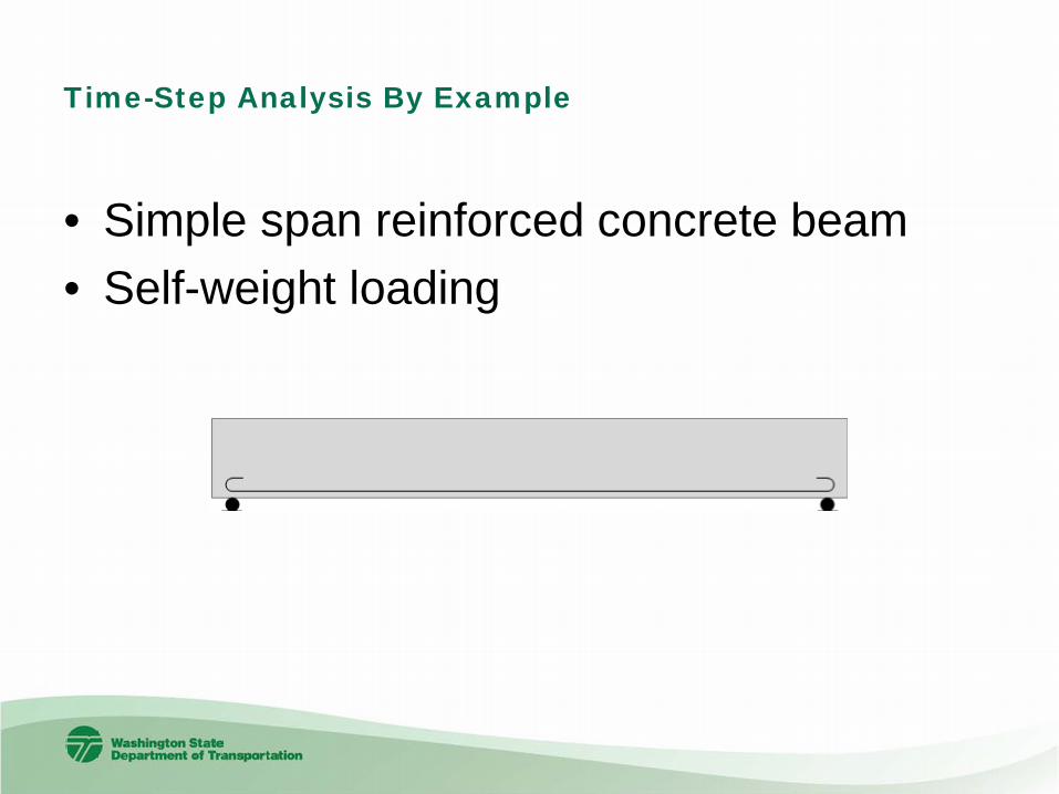
Time-Step Analysis By Example
• Simple span reinforced concrete beam• Self-weight loading

Time Variation of Material Properties
0
1
2
3
4
5
6
7
1 10 100 1000 10000
f'c (k
si)
Time (days)
Time Variation of Concrete Strength
0
1000
2000
3000
4000
5000
6000
1 10 100 1000 10000
Ec (k
si)
Time (days)
Time Variation of Concrete Modulus
0
1
2
3
4
5
1 10 100 1000 10000
Cre
ep C
oeffi
cien
t
Time (days)
Time Variation of Creep Coefficient
Day 1
Day 2
Day 3
0
0.2
0.4
0.6
0.8
1
1.2
1 10 100 1000 10000
Shrin
kage
Str
ain
X 10
00
Time (days)
Time Variation of Shrinkage Strain

Time Step 1 – Analyze Loading Condition
• Moment due to self-weight (external force)• Use transformed section analysis
– Neglect bending stiffness of reinforcement
�𝑃𝑃 = 0 = 𝑃𝑃𝑐𝑐 − 𝑃𝑃𝑟𝑟 �𝑀𝑀 = 𝑀𝑀 = 𝑀𝑀𝑐𝑐 + 𝑃𝑃𝑐𝑐𝑌𝑌𝑐𝑐 − 𝑃𝑃𝑟𝑟𝑌𝑌𝑟𝑟

Time Step 1 – Incremental Deformations
• Incremental forces on the various parts of the cross section are determined by a transformed section analysis– ∆𝑃𝑃𝑐𝑐1 = 𝑃𝑃𝑐𝑐 ,∆𝑀𝑀𝑐𝑐1 = 𝑀𝑀𝑐𝑐 ,∆𝑃𝑃𝑟𝑟1 = 𝑃𝑃𝑟𝑟
• Incremental Deformations– Computed using modulus at time of loading and net
section properties
– ∆𝜀𝜀𝑐𝑐1 = ∆𝑃𝑃𝑐𝑐𝑐𝐸𝐸𝑐𝑐𝑐𝐴𝐴𝑐𝑐𝑛𝑛
,∆𝜑𝜑𝑐𝑐1 = Δ𝑀𝑀𝑐𝑐𝑐𝐸𝐸𝑐𝑐𝑐𝐼𝐼𝑐𝑐𝑛𝑛
– Δ𝜀𝜀𝑟𝑟1 = Δ𝑃𝑃𝑟𝑟𝑐𝐸𝐸𝑝𝑝𝐴𝐴𝑝𝑝

Time Step 1 – End of Interval
0
0.2
0.4
0.6
0.8
1
1.2
1 2 3 4 5
Nor
mal
ized
Axi
al S
trai
n
Time Step
Incremental Axial Deformation in Concrete
∆εc1

Time Step 2 – Time-Dependent Effects
• Only Time Passes• Time-dependent response of materials
– Unrestrained Creep of Concrete• Δ𝜀𝜀𝑐𝑐𝑟𝑟 = Δ𝑃𝑃𝑐𝑐𝑐
𝐸𝐸𝑐𝐴𝐴𝑐𝑐𝜓𝜓(𝑡𝑡2, 𝑡𝑡1)
• Δ𝜑𝜑𝑐𝑐𝑟𝑟 = Δ𝑀𝑀𝑐𝑐𝑐𝐸𝐸𝑐𝐼𝐼𝑐𝑐
𝜓𝜓(𝑡𝑡2, 𝑡𝑡1)
– Unrestrained Shrinkage• Δ𝜀𝜀𝑠𝑠𝑠(𝑡𝑡2, 𝑡𝑡1)

Time Step 2 – Initial Strain Analysis
• Reinforcing causing internal restraint• Compute restrained deformations and
internal restraining forces, Δ𝜀𝜀𝑐𝑐2,Δ𝜑𝜑𝑐𝑐2,Δ𝜀𝜀𝑟𝑟2, Δ𝑃𝑃𝑐𝑐2,Δ𝑀𝑀𝑐𝑐2,Δ𝑃𝑃𝑟𝑟2

Time Step 2 – End of Interval
0
0.2
0.4
0.6
0.8
1
1.2
1.4
1.6
1 2 3 4 5
Nor
mal
ized
Axi
al S
trai
n
Time Step
Incremental Axial Deformation in Concrete
∆εc1
∆εc2
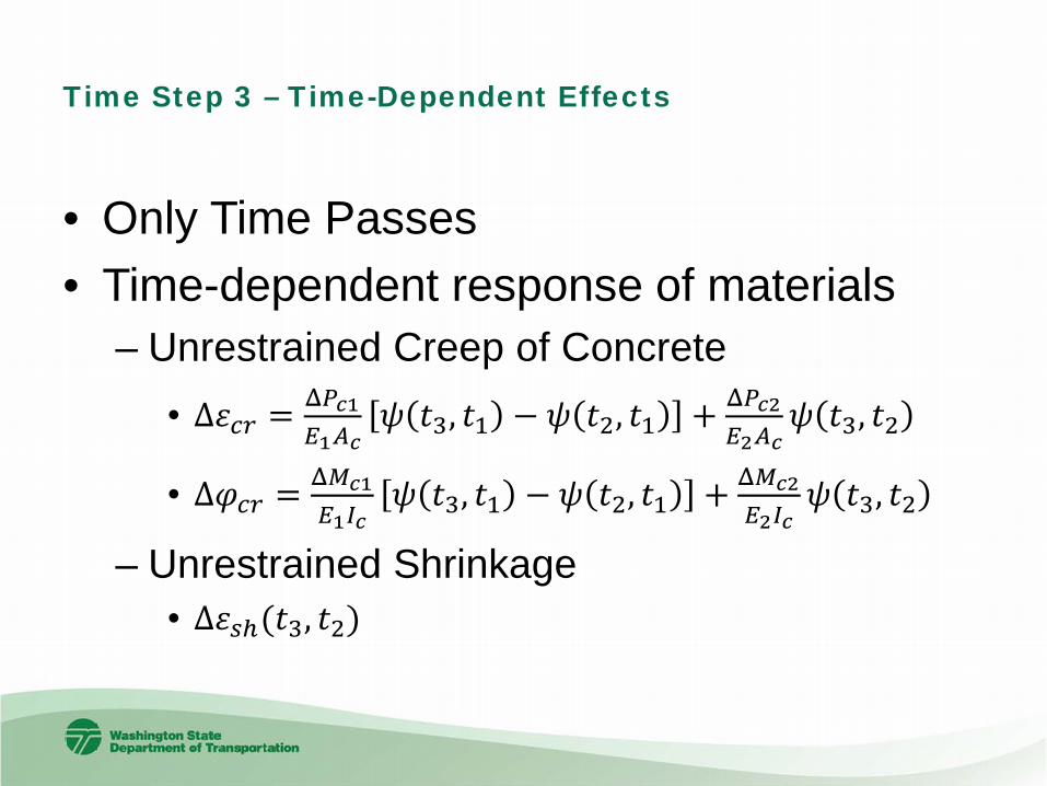
Time Step 3 – Time-Dependent Effects
• Only Time Passes• Time-dependent response of materials
– Unrestrained Creep of Concrete• Δ𝜀𝜀𝑐𝑐𝑟𝑟 = Δ𝑃𝑃𝑐𝑐𝑐
𝐸𝐸𝑐𝐴𝐴𝑐𝑐𝜓𝜓 𝑡𝑡3, 𝑡𝑡1 − 𝜓𝜓 𝑡𝑡2, 𝑡𝑡1 + Δ𝑃𝑃𝑐𝑐𝑐
𝐸𝐸𝑐𝐴𝐴𝑐𝑐𝜓𝜓 𝑡𝑡3, 𝑡𝑡2
• Δ𝜑𝜑𝑐𝑐𝑟𝑟 = Δ𝑀𝑀𝑐𝑐𝑐𝐸𝐸𝑐𝐼𝐼𝑐𝑐
𝜓𝜓 𝑡𝑡3, 𝑡𝑡1 − 𝜓𝜓 𝑡𝑡2, 𝑡𝑡1 + Δ𝑀𝑀𝑐𝑐𝑐𝐸𝐸𝑐𝐼𝐼𝑐𝑐
𝜓𝜓 𝑡𝑡3, 𝑡𝑡2
– Unrestrained Shrinkage• Δ𝜀𝜀𝑠𝑠𝑠(𝑡𝑡3, 𝑡𝑡2)

Time Step 3 – Incremental Unrestrained Deformations
0
0.05
0.1
0.15
0.2
0.25
0.3
0.35
0.4
1 2 3 4 5 6Time Step
Unrestrained Axial Creep Strain
𝜀𝜀1 𝑡𝑡 =𝑃𝑃𝑐𝑐1
𝐸𝐸𝑐𝑐1𝐴𝐴𝑐𝑐𝑟𝑟𝜓𝜓(𝑡𝑡, 𝑡𝑡1)
𝜀𝜀2 𝑡𝑡 =𝑃𝑃𝑐𝑐2
𝐸𝐸𝑐𝑐2𝐴𝐴𝑐𝑐𝑟𝑟𝜓𝜓(𝑡𝑡, 𝑡𝑡2)
Δ𝜀𝜀 𝑡𝑡3, 𝑡𝑡2 = 𝜀𝜀 𝑡𝑡3 − 𝜀𝜀(𝑡𝑡2)

Time Step 3 – Initial Strain Analysis
• Reinforcing causing internal restraint• Compute restrained deformations and
internal restraining forces, Δ𝜀𝜀𝑐𝑐3,Δ𝜑𝜑𝑐𝑐3,Δ𝜀𝜀𝑟𝑟3, Δ𝑃𝑃𝑐𝑐3,Δ𝑀𝑀𝑐𝑐3,Δ𝑃𝑃𝑟𝑟3 If reinforcement were
prestressed, this would be the change in prestress force (aka loss)

Time Step 3 – End of Interval
0
0.2
0.4
0.6
0.8
1
1.2
1.4
1.6
1.8
1 2 3 4 5
Nor
mal
ized
Axi
al S
trai
n
Incremental Axial Deformation in Concrete
∆εc1
∆εc2
∆εc3
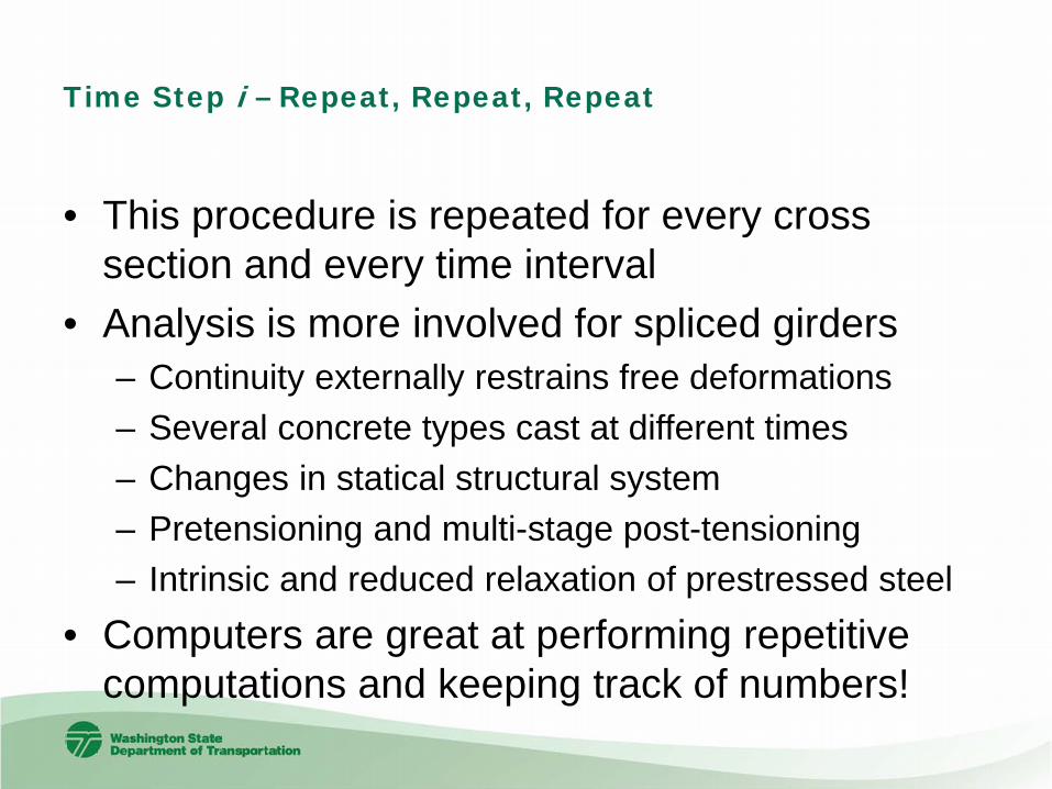
Time Step i – Repeat, Repeat, Repeat
• This procedure is repeated for every cross section and every time interval
• Analysis is more involved for spliced girders– Continuity externally restrains free deformations– Several concrete types cast at different times– Changes in statical structural system– Pretensioning and multi-stage post-tensioning– Intrinsic and reduced relaxation of prestressed steel
• Computers are great at performing repetitive computations and keeping track of numbers!

Computer Aided Design of Spliced Girders
• NCHRP Report 517 – Extending Spans– Suggests DOT produced software was a
significant contributing factor for wide-spread use of PT Box Girder technology
– Implies same will be true for adoption of spliced girder technology
– Notes the lack of a preferred industry standard– Recommends owner agencies and industry
pursue development of high quality software tools for spliced girder bridges

PGSplice™
• Part of the new WSDOT BridgeLink™ suite of software• Design, analyze, and load rate continuous precast-prestressed spliced
girder bridges• Modeling
– Cantilever pier segments– Drop-in field segments– Temporary erection towers– Strong back hangers– Multi-stage post-tensioning
• Analysis– Non-linear time step analysis– AASHTO, ACI 209 and CEB-FIP Model Code
• User interface, modeling, graphing and reporting features are very similar to PGSuper™

Bridge Configurations4 Span Variable Depth Girder with Cantilever Piers Segments and Drop In Field Segments
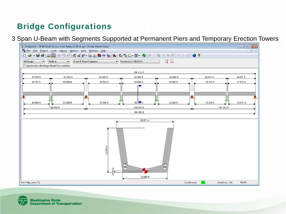
Bridge Configurations3 Span U-Beam with Segments Supported at Permanent Piers and Temporary Erection Towers

Bridge ConfigurationsEnd Spans are pretensioned girders - center span three segment spliced girder

Graphical Results
• Visualize Complex Results with Simple Graphical Representations

Detailed Reporting
• Transparent – eliminate frustration with “black boxes”

Case Study
• Two Span Continuous Spliced Girder Bridge• Presented in PCI State-of-the-Art of Spliced-
Girders report

PGSplice™ Models

Baseline Comparison
-2.5
-2
-1.5
-1
-0.5
01 10 100 1000 10000
Stre
ss (K
SI)
Time (Days)
Top of Girder Stress at 0.4L in Span 1 without Time Dependent Effects
Abdel-Karim
PGSplice

Comparison including Time-Dependent Effects
-2.5
-2
-1.5
-1
-0.5
01 10 100 1000 10000
Stre
ss (K
SI)
Time (Days)
Top of Girder Stress at 0.4L in Span 1 with Time Dependent Effects
Abdel-Karim
PGSplice

Software Availability
• Free download from WSDOT• http://www.wsdot.wa.gov/eesc/bridge/software
• Open Source• BridgeLink™ v1.0
– PGSuper™ v3.0 (Beta)– PGSplice™ v3.0 (Beta)– BEToolbox™ v3.0

http://www.wsdot.wa.gov/eesc/bridge/software