Embed Size (px)
Citation preview

Computational Modeling of Hall Thrusters
Justin W. KooDepartment of Aerospace Engineering
University of MichiganAnn Arbor, Michigan 48109
Overview
• Motivation• Hall Thruster Background• Computational Modeling• Results• Acknowledgements

Rocket Equation
• Force balance on a spacecraft
• Neglect gravity and drag forces and integrate
Exit gravity drag
dv dmM U F Fdt dt
expfinal initialExit
VM M
U
Mission V Requirement
Earth to LEO 7600 m/s
LEO to GEO 4200 m/s
LEO Escape 3200 m/s
LEO to Moon 3900 m/s
LEO to Mars 5700 m/s
Table from Mechanics and Thermodynamics of Propulsion, 2nd Edition, Peterson and Hill, 1992

Specific Impulse
• Thrust per unit mass propellant (measured in s)
• Put this into the rocket equation
exitsp
propellant e e
Tdt UI
m g g
expfinal initialsp e
VM M
I g
Chemical vs EP
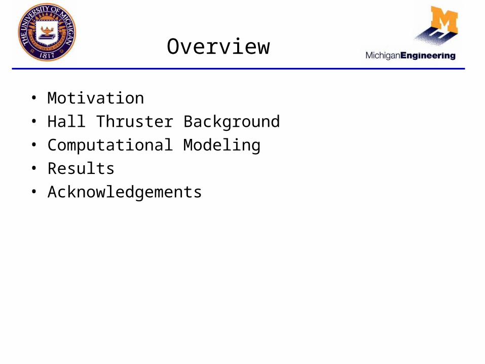
• Chemical Propulsion– Limits on propellant exit velocity are based on thermodynamic
properties of propellant and material properties of combustion systems
– Typical Isp between 150 s and 450 s
– High thrust applications (especially Earth to LEO)
• Electric Propulsion (EP)– Limits on propellant exit velocity are based on power supply
mass and lifetime issues– For Hall thrusters typically between 1500 s and 2500 s– Low thrust applications (LEO to GEO and beyond)
– Tradeoff between thrust and Isp

LEO to Mars
• Suppose v = 5700 m/s is required• With typical bipropellant chemical propulsion
– Isp = 250 s– Ideal Payload Fraction = 9.8%
• With EP (Hall Thruster)– Isp = 1600 s– Ideal Payload Fraction = 69.5%
• Primary present application is to satellite stationkeeping which requires small V corrections over a number of years with savings of hundreds of pounds on satellites that weigh thousands of pounds

Hall Thruster Performance
• UM/AFRL P5: 3 kW, 300 V, 10 A operating condition with a thrust of 180 mN, Isp of 1650 s, and efficiency of 51%
• NASA-457 M: >50 kW operating condition with thrust of nearly 3 N, Isp of 1750s - 3250 s, and efficiencies of 46% - 65%
UM/AFRL P5 Photo courtesy of PEPL

Hall Thruster Schematic
Schematic courtesy of PEPL
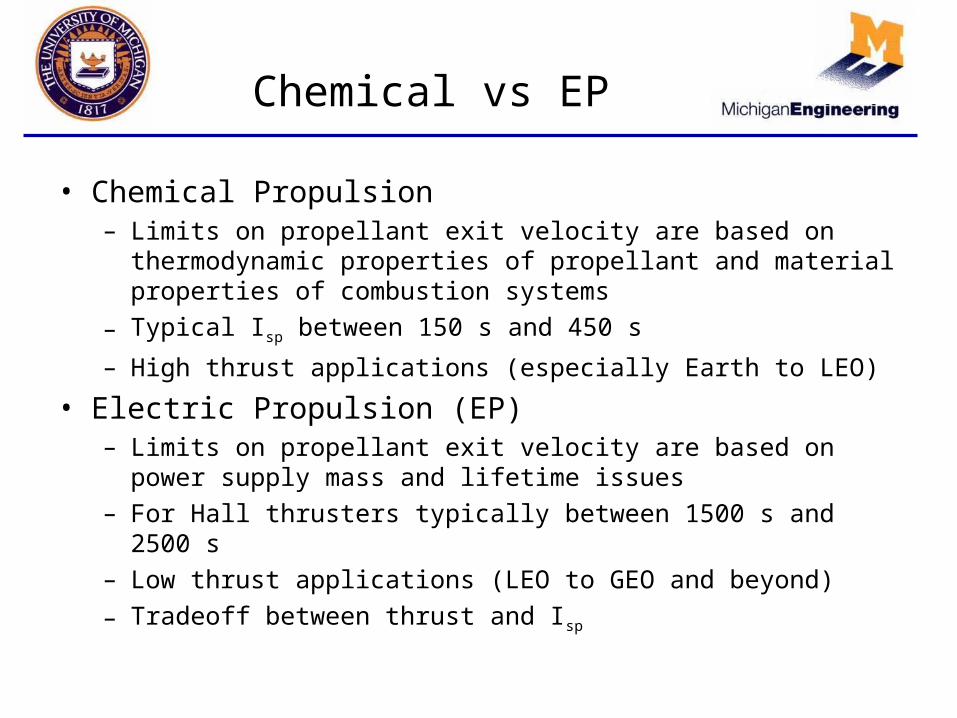
UM/AFRL P5
UM/AFRL P5 Video courtesy of PEPL

Modeling Benefits
• Many good reasons to develop computational Hall thruster models– Spacecraft Integration
• Existing plume models need better boundary conditions at the device exit
• Contamination of solar panels and sensitive instruments
– Quantify chamber effects• Vacuum chamber performance of Hall thrusters is affected by finite
neutral background density
– Virtual life tests• Thruster lifetimes (>8,000 hours) require erosion modeling to
determine lifetime limiting design characteristics
– Understand physics relevant to thruster operation • Experimental measurements inside device are limited by probe
dimensions, probe lifetime and other (optical, RF) access issues
Computational Model
• 2-D axisymmetric hybrid PIC-MCC• Domain includes acceleration channel and near-field of
dielectric wall-type Hall thruster• Based on a quasi-neutral plasma description• Heavy particles (Xe, Xe+, Xe++ ) are treated with a PIC-
MCC model• 1-D energy model assumes isothermal maxwellian
electron distribution along magnetic field lines• Plasma potential based on Ohm’s Law formulation• Anode region potential model based on generalized
analytic Bohm criterion

Computational Schematic

SPT-100 Plasma Density

SPT-100 Potential

Mobility Modeling
• Calculated from classical transverse electron mobility form:
• Electron momentum transfer frequency is supplemented by a modeled bohm mobility term or wall-collision term
2
,
1
1
emom B e
mom
e
m

P5 Mean Plasma Density
Experimental Computational

P5 Mean Potential
Experimental Computational
Acknowledgements
• Department of Energy Computational Science Graduate Fellowship