Embed Size (px)
Citation preview

Computational Model of AquacultureFin-Fish Net-Pens
H. GignouxL.D. Thompson
and
R.H. Messier
Department of Mechanical Engineering, University of MaineOrono, Maine
Introduction
This work is sponsored by Sea Grant, the School ofMarine Sciences at the University of Maine and DefenseAdvanced Research Project Agency DARPA! and wascompleted at the University of Maine, Orono, Maine fromSeptember 1996 to May 1997. This work is an outgrowth ofwork done by Messier and Thompson [1] for DARPA inmodeling Very Large Floating Structures VLFS!. The dynamicstructural response of a VLFS and typical floating net-pendesigns are similar, though of vastly different scales. With afew notable exceptions, net-pens are typically made up ofstructural beam elements assembled to form a buoyant framethat supports the net pen.
In the last 10 years aquaculture of salmonids hasexpanded from 5.7% �985! to 34.5% �994! share ofworldwide production. Originally developed in the Norwegianfjords, the industry has expanded to protected and exposedlocations in Canada, Ireland, Peru, and the United States toname a few major salmon producers. With the collapse of manytraditional fisheries worldwide, market forces are pressingdevelopment of the aquaculture of market species such as cod,fluke, and halibut. Recent developments in the New Englandarea show promising startup projects of these species with thebacking of both public and private capital. Similar projects areoccurring elsewhere in the world. Due to environmental,regulatory, and user conflict constraints, future expansion offish farming will be in more exposed, high energy locations.
107

This shift requires improved analysis of net-pens to determinetheir performance and survivability in a high energy locations.
To provide an additional tool to evaluate the performanceof net-pens, computational models using Finite ElementAnalysis FEA! method were developed and applied to net-pendesigns used in salt water aquaculture. A commercial FEAsoftware package, ABAQUS AQUA", was used in developingthese models. The objective of this research is to identifyfailure modes and predict estimated life cycles of net-pendesigns in different ocean environments. Successful applicationof this analysis will provide aquaculture managers, operatorsand regulators with increased understanding of the performanceand survivability of a particular net-pen design under theapplied sea state. This paper describes the development andapplication of this tool on two different net-pen designs.
Theoretical Considerations
The theoretically important aspects of this research arediscussed below. They include: nonlinear dynamic finiteelement method, Airy wave theory and its application throughMorison's equation, and the mapping technique used to modelthe containment nets.
Nonlinear Dynamic Finite Element Method
When studying the dynamic response of a structure usingthe finite element method, a determination of the appropriatesolution algorithm, implicit or explicit, is required. Belytschko[2] suggests that the problem be classified as either an inertia orwave propagation problem. Wave propagation problems requirean accurate reproduction of the wave front e.g. the response ofan impact! and are best solved using an explicit time integrationscheme. Inertia problems, or structural dynamic problems, arelow frequency response problems such as large displacement.These are best solved using an implicit time integrationscheme. Clearly the structural response of net-pen in an oceanenvironment is of an inertia type requiring an implicit solutiontechnique. Due to the large deformations of the netting and
108

M "uI�+ I+<! I I,�, P" � I�! � < I" I, P" � I,!+ L'I�. = 0[Eq. 1]
id�~ = ul, +M[� � ygl, +Ml�~] [Eq. 2]
Lll f ~~ ltd + hl tltlg +At P gl I +ptt li++ i [Fq 3 ]1
2
where: � � CX 0; P; g = � � u;3 4 2
The consistent mass matrix is defined as:
M = P.N N dV. �l4!V,
[Eq. 4!
The internal force vector is defined as:
N t tieI = J P . odV� note gg p!V�
[Eq. 5]
The external force vector is defined as:
P = N tdS+ N FdV [Eq. 6]
The Lagrange multipliers are defined as: L~ = XLagrange Multiplier Forces.
The parameter, tx, controls the numerical damping of thesystem. Hibbitt and Karlsson [4] have empirically found the
109
relatively large wave heights to be modeled, nonlinear, non-symmetrical analysis was selected. This allows the stiffnessmatrix to be reconstructed at each time step to account for thegeometric changes in the structure. The finite element solutionalgorithm uses a modified Newmark family of equations as thebasis of the implicit nonlinear solution algorithm. The nodalequations are:

most effective value for o to be -0.05. This reduces the
"ringing" caused by the automatic time stepping and gives goodagreement with analytical solutions.
Airy Wave Theory
Airy wave theory is a linearized adaptation of the flowpotential, P. This method allows multiple wave trains to besuperimposed over each other to build a good approximation oftypical sea state spectrum found at any particular site. Thismethod was used in the analysis presented here. Airy wavetheory makes the incompressible, inviscid, irrotational flowassumption over a flat bottom. It further assumes that the wavesare planar and the wave amplitude is "small" compared thewater depth. This allows the flow potential, P, to be defined as:
V P = 0, with the fluid particle velocities define as:
dpv = . Solving for equilibrium yields:
o!'P dv 86 opPp � + �.v = � p � ��
&Bf A W ck [Eq. 7]
where
P Fluid densityP Pressure
Gravity constantG = g z � z ! Potential energy per unit mass
Applying the boundary conditions and throwing out thehigher order terms to linearize the theory yields the followingset of equations that define the fluid particle attributes.
Horizontal fluid displacements;
g 0 'r cosh[�x/1 ! z � z,!] I s I 0Sill 2K � � � +
omprinern ~N ~0~~[�+ ~ ~N ! z, zg ! ] N N[Eq. 8]
110

Vertical fluid displacements;
a�r", sinh[�tr I l ! z � �!] s t 0cos2tt � � � +-
< Imeoiienfs g cosh[�tt 1 ~g ! , rb!] N rN[Eq. 9]
For these equations to be valid, the following inequalitiesmust be true:
H d� 0.03, � ! 20, and the Ursell parameter,d
«1
where H is the wave height, k is the wavelength, and d isthe water depth. Figure l portrays the nomenclature for a singlewave train.
Figure 1. Wave Train Nomenclature.
By superimposing multiple Airy wave functions, themodel can replicate the wave spectra of a particular net-pensite. The wave history of a typical Sea State 5 is shown inFigure 2. Additionally, the FEA code allows constant velocitycurrents to be modeled variable with position as well.
111

72 m
ettl 0
Amplitude l
2 m0 20 40 60 ttu IUUt 1200 I
1tme tutti
Figure 2. Generic Sea State 5 Time History.
Morison's Equation
The FEA code uses Morison's equation Morison et al.1950! to apply the wave and current forces to the structure.This is an uncoupled scheme that applies the buoyancy, drag,and inertia forces, due to the fluid, to the immersed beamelements of the structure. Morison's equation for a verticallyaligned cylinder of differential length, dz, that is displaced ahorizontal distance, tl, is:
pCd D i i pC~ttD a ptlDdF = � 4 u � rj! u � tl~+ 4 � C � l!re
2 4 4 m
[Eq. 10]
where:
112
a
C,C
dF
D
dz
u
Horizontal fluid acceleration
Drag coefficientAdded mass coefficient
Horizontal force per unit length of the cylinderEffective cylinder diameterUnit length of the cylinderHorizontal fluid velocityHorizontal velocity of the cylinder
Horizontal acceleration of the cylinderWater density

F, = � ftp,r,' � f,p,r,'!tg [I � tt]dx dn, dx dn, 1
*~"" ''~' ~f' ~[ 'd5 45 'd5 d5JdS
[Eq. 11]
where
f~ = [ 0 if the elevation is above �'1 otherwise
f;=[ 0 if the elevation is above z,,1 otherwise
and
g gravitational accelerationn, first normal of beam cross-sectionn, second normal of beam cross-sectionr outside radius of the pipe sectionr, inside of pipe sectionS distance along beam centerlinez free surface elevation of fluid outside of pipez, free surface elevation of fluid inside of pipep, mass density of fluid inside of pipep mass density of fluid outside of pipe
Drag forces on immersed beams is broken into thetransverse and tangential drag forces to the beam element. Thetransverse drag force per unit length is calculated as:
F�= ~pCnDftv�~kv, Av�. [Eq. 11]
113
The program determines whether a beam element isimmersed, and then applies the appropriate buoyancy, drag, andinertia forces as defined below. Buoyancy forces are appliedonly to vertically aligned cylindrical beam elements. To applybuoyancy forces to a beam element that is not verticallyaligned, fictitious vertical beam elements are added to themodel as appropriate. The buoyancy force per unit length of abeam element is calculated as:

For tangential drag forces, the force per unit length isgiven by;
F, = ,'�pC,aDAv,gv,~ [Eq. 12]The inertia force per unit length for a submerged beam
element is given by;
F, = vp aD' [C� a, � a z tt! + C, a, � a, tt ! ][Eq. 13]
where
a Acceleration of a point on a beamP
a, Fluid particle accelerationC Transverse added mass coefficient
C Transverse drag coefficientC Transverse inertia coefficient
C Tangential drag coefficienth Tangential drag exponentt Unit vector defining the axial direction at a
point in a beamAv = dv � hv Relative transverse velocity of the fluidhv, = hv ~ t!t Relative tangential velocity of the fluidv, Fluid particle velocityv Velocity of a point on a beam
Phv vf QR v Rel ative fluid velocityct, Structural velocity factor
The specific coefficients for drag and inertia of a beamelement are determined experimentally, or analytically forcertain shapes.
Net Mapping Equations
Typically a net mesh panel subjected to uniformdistributed force acts like a two dimensional catenary, i.e. thenet strands have little or no bending stiffness, but havemeasurable axial stiffness in tension. The FEA code appliesdrag and inertia forces due to a fluid to be applied to beamelements. To remove the artificial stiffness in beam elements
114
and to reduce the number of elements required to model thecontainment net, a net mapping algorithm was devised.
The individual net mesh strands are collapsed into acoarser net mesh. Figure 3 shows the process and theterminology used. Typically for grow out of salmonids, 63.5mm �.5 inch! nets are used. This gives an average strandlength of 31.7 mm. The mapped strand length is typically in theone meter range.
Figure 3. Nel Mapping Terminology.
mappedThis yields a mapping ratio,
orp[Eq. 15|
For the structural response, the key parameter is the crosssectional area.
omapped org ort, [Eq. 16]
For the drag forces, the key parameter is the effectivediameter:
[Eq. 17]mapped org
115

To reduce the structural response due to bending, themoment of inertia for the strands are set near zero.
To validate this method, a test panel of the actual meshand the mapped mesh was inodeled and run under differentcurrent scenarios. The reaction forces from these tests were
compared to the test results of actual nets is a test tankconducted by Mannuzza [3j. These validation checks showedexcellent correlation, less than 5% difference.
Model Development
Development of the FEA net-pen models was divided intothree tasks for each model:
~ Structural frame development,~ Containment net mapping and development,~ Sea state and current extraction.
Both FEA models use the metric MKS! system of units.All information that is in non MKS system units was convertedto MKS to assure consistency. The structural framedevelopment was performed using ABAQUS Pre"preprocessor software. This software provides the basic inputfile that ABAQUS AQUA" uses to define the initialgeometric, structural, and material properties of the FEA model.MathCad 6.0+" was used to develop the net mappingalgorithm and sea state properties. This information was used torevise the input file as required.
Model One Development
Model One is an octagonal floating net-pen design that is20 m across with a pen depth of 10 m. Figure 4 shows thelayout excluding the moorings. The floating support ring is asteel box fabrication, one meter m! wide by m deep. 1tprovides the structural rigidity and attachment points for themooring system and containment net.
The mooring system cnnsists nf eight mooring blocksconnected to the mooring buoys by chain. Poly-steel cable�.038 m. diameter! connect the mooring buoys to the corners
lie
Figure 4. Model One.
of the frame. The net-pen is moored in 30 m of water. Tosimplify the model, the mooring chain is modeled as a non-linear spring that mimics the response of an actual mooringchain acting as a catenary connector.
The containment net is made up of eight, 8 m by 10 mpanels hung square from the frame. The net mesh modeled is63.5 mm �.5 in! square, knotless nylon mesh. A steel octagonalring is fastened to the bottom edge of the containment net tostabilize the containment net in high currents. The bottom ofthe containment net was not modeled to reduce the effects ofnumerical buckling. The mapped containment net has a strandlength of one m yielding an a ratio of 31.
Model Two Development
Model Two, designated the Pull Up Pen PUP!, is aprototype submersible design being developed by the OceanEngineering Center of the University of New Hampshire. It isdesigned for deployment in an open ocean environment withwater depths in the 60 to 120 m range. It consists of a 20 m

long by m diameter spar buoy moored to the bottom in atension leg conhguration, A 4.5 m long aluminum frame slidesover the spar buoy. The frame can be raised and lowered fromthc surface to the ocean bottom. Attached to thc frame are four,
3 m diameter by 3 rn deep cy]indrical net pens arrangedsynunetrically around the sleeve. Figure 5 shows the layout.
Figurc 5, Mocl l Tev~ lxv!out,
Each containment net is ntade up of three parts, afloatation collar at the top, a steel ballast collar at thc bottom,and the containment net connecting the two. The floatationcollar is made up of two, 76 tnm � inch! diameter high densitypolyethylene HDPE! tubes formed into 4 m diameter ringsseparated vertically by a rn. Trawl floats are attached to thecontainment net between the HDPE rings to provide positivebuoyancy to thc containment net. The upper ring is shackled 1.othe frame. A steel ring forms the bottom perimeter of thecontainment net to stabilize the containment net shape. Steelcables secure thc bottom ring to the lower frame, The net meshmodeled is 63.S rnm �.5 inch! square, knotless nylon mesh.
118
The mapped containment net has a strand length of 0.3 myielding an a of 9.5.
Results and Conclusions
The FEA models provide nodal displacement and stressand strain information at the element integration points for eachtime step. The wealth ol data available can be overwhelming.What will be discussed here are the significant data for theelements that are key to visualizing its response and predictingits life cycle.
To predict the expected life cycle of a net-pen, theendurance limit or fatigue strength of its materials need to bedetermined. If a material is subjected to cyclical stresses greaterthan its endurance limit, the material will eventually fail due tofatigue. To determine the endurance limit of a material, thetensile strength of that material is modified by a number offactors that take into account the method of manufacture,environmental effects, and size to name a few. With acalculated endurance limit, a factor of safety can be calculatedfor those elements.
Model One Results
Model One was subjected to three different runs orscenarios. During Run One, the model was subjected to asteady 1.5 m/s � knot! current. During Run Two, the modelwas subjected to 0.05 m/s current and Sea State Five SS5!waves. During Run Three, the model was subjected to a steady1.5 m current and SS5. All currents and wave trains flowed inthe positive 1 x! direction
For Model One, the critical member analyzed is the mainsteel frame. The endurance limit for the steel in the structurewas determined to be 67.2 MPa which is 16.8% of its tensilestrength �00 MPa! or 26.9% of its yield strength.
Comparison of net-pen deformations
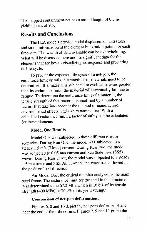
Figures 6, 8 and 10 depict the net-pens deformed shapenear the end of their three runs. Figures 7, 9 and 11 graph the
119

vertical motion of the main frame as a function of time. Nodes
1, 5, 9 and l3 are in the center of the right, bottom, left and topsides of the frame respectively.
Figure 6. Run j Deformed Shape.
QS gS 4aa, Q U I
, SS~ SSS SSI I I 92 ~ s ll
~ If
SSI ~-~ sm l.Sill~ I S.I SSI ~ SSSSS S.S ~ II IS
Figure 7. Vertical Displacetnents.
120
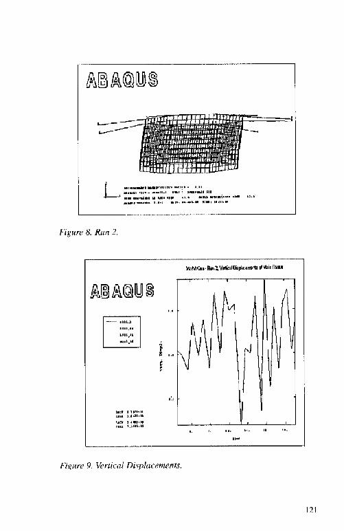
Figure 8. Run 2,
Figure 9. Vertical Displar:ements,

Figure 10. Rutt 3.
Figure 11. Vertical Displacements.
The loads are ramped up over the first two seconds, Thestrong current in Runs l and 3 cause a large deforination of thecontainment net even with the weighted net ring. Without it, themodel fails dne to Euler buckling in the net mesh when runwith a 1.5 rn/s current.
t22
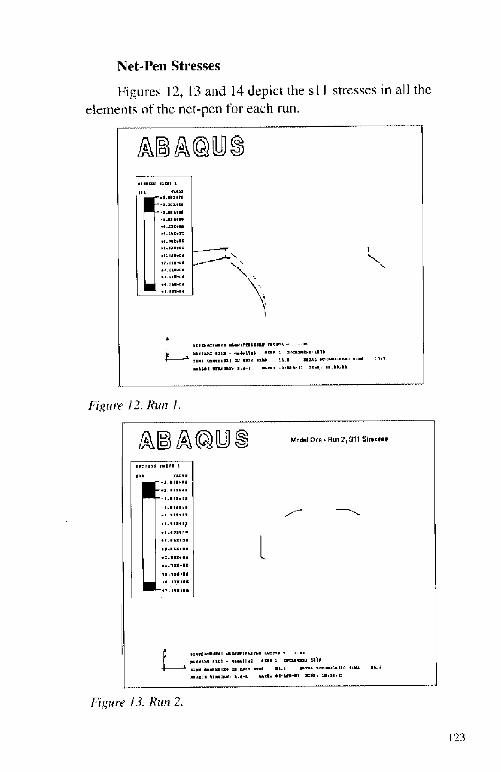
Net-Pert stresses
Figures l2, 13 and 14 depict the s 1 1 stresses in all theeletnents of the net-pen for each run.
I 'I I & WhL I t ~t lllI Ql
Figure i2. Run l,
Figure l3. Run 2,
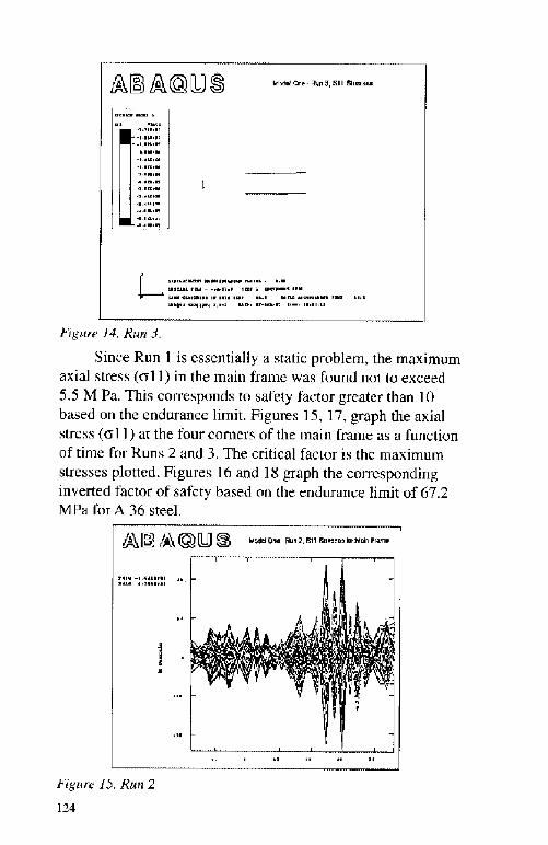
M>dd Cee- Rgn 3,811 Sires
~ ~acg t ll5.I tll14 4RI B1 ~ 1LI-Jt1- ~ 'I 92 I ~ Kl ll
Figure I4, Run 3.
Since Run 1 is essentially a static problem, the maximumaxial stress al 1! in the main frame was found not to exceed
5,5 M Pa. This corresponds to safety lactor greater than 10based on the endurance limit. Figures 15, 17, graph the axialstress a1] ! at the four corners of the main Irame as a function
of time for Runs 2 and 3. The critical factor i» the maximum
stresses plotted. Figures 16 and 18 graph the correspondinginverted factor of safety based on the endurance limit of 67.2MPa for A 36 steel.
Figure IS. Run 2
124

Figure 16.
Figure l7, Run 3
Figure l8.

Model Two
The PUP is designed for operations in both .r surfaced andsubmerged mode. The primary objective of this analysi» i» topredict the rnaxirnum sca states the model can be operated atboth the surface and subnrerged at 10 m. A secondary objectiveis to predict failure points and modes in the structure. Thi»information will alhrw thc developers to adjust the constructiondetail» to improve the survivability of thc PUP.
Surface Mode
To find the member» that were most likely to fail, thcmodel was subjected to Sea State 5 in its surface mode. Asexpected, both the containment net support frame and theHDPE rings failed due to Euler buckling and plastic strain ducto bcndirrg, The other rnembcr», piling, netting. lower ring, ctc.,arc not critically loaded. Thc following results details thedisplacements and stresses of the support frame and HDPErings for both operational modes. The model was subjected todecreasing sca states until the model ran well, In its presentconfiguration, the rnaxirnurn sea state that the PUP should bcexposed while at thc»urfacc is Sea State 2 H < 0.5 rn, X > 3,5rn!. Expo»cd to SS2, the critically poaded members are theconnectors between the upper frame and the HDPE rings andthe lower 1'rar»e. Figure I9 details thc displacement» of thcPUP, Figure 20 portrays thc rrI I stresse» for the entire franre.
Fig>rr re l<!. PUP Sar j<r e Mode.
126

MR<~ <% < ~ << 92 I ILf I -92'I Nl
I'i <,»ate 20. F<ru»e .S't!esse.<,
The maximum stresses in both the nct connectors and the
lower frante exceeded the yield strength �50 M Pa! of thcmaterial as modeled. Adjusting the cross-scctiona] shape shouldreduce the stress levels in these members. Future v ork will
concentrate on improving these elements,
Submerged Mode
Thc PUP was suhtncrgcd to a depth of 10 m, A point massof 2000 kg was added to thc bottom of thc frame to balance thebuoyancy of thc trawl floats. A spring was added between thcpile and lrame to keep the net-pen from sinking or surfacin< .The trarne is sti]l allowed to slide along the piling. As anode]ed,the PUP perfor<ns well up to SS4 H < 1.8 m. k > 15.5 tn!, It i»cxpccted tha . improvements to thc surf <ce mode tnt']e] willimprove its pertormancc when submerged.
Figure 21 detail» the displacements of he nct-pcn. Rcddepicts thc model in its initial, undeforincd shape, Figurc 22portrays the s11 stresses in the frame,

Figure 21. PUP submerged,
Figure 22. Frame Stresses.
t28

Final Thoughts
An important aspect of this work that is not yet completedis to validate this technique with experimental results.
Individual parts of the models have been validated e.g.the net mapping, and the structural response of the frame!, butthe response of the entire model needs to be validated. Asfunding becomes available, researchers at the University ofMaine plan to complete this portion of this project.
With the validation completed, these models will start alibrary of FEA net-pen models. Additional models will beadded to this library as needed. Aquaculture researchers,designers, and operators will have a useful tool to evaluate theperformance and response of these designs under the appliedconditions.
References
Messier, R.H. and L.D. Thompson. 1996. A Nonlinear Finite ElementAnalysis Technique for Semi-submersible Platforms Under Wave andCurrent Excitation, University of Maine.
Belytschko, T. 1986. Overview of Semidiscretization, Computational Methodsfor Transient Analysis, Ed. Belytschko T., Elsevier Science PublishersB.V., Amsterdam, pp. 55-59.
Mannuzza, M. Hydrodynamic Forces on Floating Off-Shore AquacultureCages, Thesis, University of Maine, 1995
Hibbitt and Karlsson. 1994. ABAQUSIStandard Users Manual I, Hibbitt,Karlsson & Sorensen Inc.
Hibbitt and Karlsson. 1994. ABAQUSIStandard Users Manual II, Hibbitt,Karlsson & Sorensen Inc.
Hibbitt and Karlsson. 1994. ABACUS Theory Manual, Hibbitt, Karlsson &Sorensen Inc.
Berteax, H. 1976. Buoy Engineering, John Wiley & Sons, New York.
Sarpkaya, T. and M. Isaacson. 1981. Met hanics of Wave Forces on OffshoreStructures, Van Nostrand Reinhold Co., New York.
Shigley, J.E. and C.R. Mischke. 1989. Mechanical Fngineering Design - 5thEd., McGraw-Hill Inc., New York.
129


The Effect of Currents and Waves on SeveralClasses of Offshore Sea Cages
Gary F. Loverichand
L ingley GaceOcean Spar Technologies, OSTBainbridge Island, Wa»hington
The primary characteristic of concern in sea cage designis that "water in the ocean moves." We don't w;int to belaborpoints we all understand, but the major water motions resultfrom waves, tidal cycles, general ocean circulation, wind shearand storm surges. At any oceanic site. water will move due toone or more of the»e causes. This will always happen and it isnot a question of if, but when�how often, and of what natureand magnitude?
Some sea farming takes place in areas of minimal watermotion and these sites were initially the most sought afterlocations. Sea cage usage i» based upon models thought to workwell at these still water sites. However, now it is generallyaccepted that water motion i» a benefit because it is needed tocarry fresh oxygen to the fish and to distribute their wasteproducts over an area broad enough for natural decomposition.When water moves, it is clean and free to the farmer and theenvironmental costs are very low because waste is reducedwithin the marine system. Within practical limits more watermotion is better for sea farming Ref. I !. As we go offshore, wehave no choice but to accept that sea farming will take place inmoving water, so we must accept the next truth, that the seacages best serve their purpose if the motions and deformationsof the cages are minimized or, at least, optimized. Acceptingthese facts, our primary design philosophy at OST can then bestated as follows:
I! We believe that the good health of the fish requires astable and fixed growing volume. Consistent, repetitive,natural and predictable fish behavior patterns can only beestablished within sea cages of stable shape and volume.
13l

2! We believe that the sea farmer is best served in his
business and operation when the growing volume isfixed, definable and effective.
3! We believe that the further evolution of the sea farmingindustry, both inshore and offshore, requires, at least, ataut netting foundation upon which new equipmentand techniques can be developed.
4! We believe that the future sea farming industry musthave available cage designs which experience minimalmotion, distortions and stresses caused by waves.
5! The industry must have these sea cages designed as ahealthy and safe system integrated into the largermarine habitat.
6! Finally, these sea cages must be provided at a cost thatpromises an attractive return on investment.
The sea farming industry is daily exposed to "new cage"designs or "improved" cage designs which promise oceanperformance. In order to make sense of this marketing and salesbombardment and to predict the performance of the many cagedesigns, it is necessary for someone to classify the differentdesigns according to expected and achievable performance.Based upon the fish habitat requirements and engineering needsfor a stable and well defined geometry, we have chosen toestablish sea cage classifications based upon the structuralmeans used to fix the growing volume. This approach isabsolutely essential if we are to accurately assess our risksgauge the potentials and answer the tough questions beingasked by the critical public.
We have defined four sea cage classes:
Class 1 gravity cages rely on buoyancy and weight to holdthe cage shape and volume against externally applied forces.Figure 1 illustrates the typical configuration.
132


Class 2, Anchor Tensioned Cages such as Ocean Spar ScaCage shown in Figure 3, rely on anchor tension to hold theirshape, If' these cages are placed in a zero gravity situation theywill still retain their full shape and voluntc. Thc application ofoutside water forces to the netting enclosure will cause theanchor line tensions to increase which resists cage deformation.
C ~Q
Figure 3. Class 2 A uh >r T usi >ued .S 'a C q> � 0 > .S > a.
However, they will not retain shape unless anchor tensionis provided. This nteans that anchor tensioned cages need to bcfixed at the site and. thus. they are stationary or immobileca<es,O
Class 3 sc > cages arc self tensioned and self supportingcages such as Sca Station. shown in Figure 4. These cage~ willhold their shape in the absence of gravity but v ill also do sowithout any anchor linc tensions, The sell tensioning structureresists stet de form atH!ns.
Jig«re 4. Cl ss 3 5'emi-Rigid Se t Statian.

1 of beams and columnse is made entire y ob 1 d''dt a a . nl ~b ropesandnot ycoi
'dit o id � bere, ', . biht and ngi i y1buoy which in turn is connec
.a es are characterize y"b 1 dpp ' res made up of jointe earns, .
tandin compressiore 5 illustrates one possi e .'blbending loads. Figure 5 i ustra
Figure . 'a. ', . t C.it i.5. Class 4 Rigiil 5ett C.itge.
sha e in zero gr;ivity aand netpre, ' ternal structurare resisted by inte . 't
s characterized by several o ' t e ah t several vearsd with in the pas s
. ea ca e classes, we can
n th class of sea cage.pe or nce ba , . .. . e.sedu,on c ... e.ca e selection or pa
i ' b
ost important of a,os ' ' all, those involve in . e na ' nein' the technology an p " ' ' ed rofitability once
h '1genera per '1 formance can be . p; ro

presented by the differing designs within the same sea cageclass. With this as our guide�we can now discuss the generalbehavior of each sea cage class in moving water.
General Performance in Currents
Currents cause the greatest loads on any of our sea cageclasses and yet because netting is mostly made of holes, thedrag forces need not be extreme for properly sized netting. Thegravity cages are too compliant, and like a window curtain or aflag in a strong breeze, deform and flap in the water with thenet result being a severe reduction in growing volume and somereduction in hydrodynamic drag. The deformations causeunpredictable, high loads on individual twines, with theresulting higher potential of failure. On the other hand, the seacages class 2 through class 4 resist current deformations, butcan experience greater drag forces as a result. The three higherclass sea cages have a similar response to the currents, so thesecan be compared as a group against the gravity cage.
For a comparison, in moderate currents a typical sea cagenet panel, normal to the current experiences a drag on the orderof 2500 kg. The shape response of this net panel can beapproximated by knowing the material elasticity, the drag forceand the forces resisting deformations. Figure 6 shows anidealized cross section of a two dimensional net paneluniformly loaded to 42 kg/M2 and analyzed using a non linearfinite element technique.
Here the collapse of a gravity net cross section is shownfor different suspended weights and compared with theexpected and observed deformation in the higher class cages,which are minimal. The volume efficiency of the gravity cagesis considerably less than that of the higher class cages. Withouttaking into account three dimensional deformations, the totalvolumetric efficiency of the gravity cage can be estimated bythe depth efficiency percentages shown at the bottom of eachsection. The maximum tensions in the individual twines are
also illustrated in this figure and shown at mid sections. In eachof the gravity net panels a buoyancy force, shown by the
l36

REQUIRED BUOYANCYT5 KGIM
OEFORMATIONSILQA ~ ING OF NETTING STRIP1 0 M IONG 2 10 6 DEEPSVSJECTTO CURRENT LOADINO = 10 60 KGIM2NFTTING MAI RIAL-NVLQNGSEE FEA FK F-NETSl RIP DEN 19 KGIM
t
2 68 GJTWINE
2 82 KGITVIIINF
4255 3 27 KG/TWINE15 5 KGIM
5P" ' I
NOSVQXANCVRFOUI RED
4 46 KGIT WINE' $~"55'- 55
< J33 3 KG/M 815
667 KG/M
OCEAN SPARRECIV I RED WE I GI4T
NET SHAPES AND LOADINGIN APPROXIMATELY 50 CIVI/SEC CURRENT
Figure 6. JVetiing Cross Ser u'onL
vertical arrows, is needed to oppose the suspended weights andthe net section drag. In order to get an approximation of theweight and buoyancy required for an entire cage, the valuesgiven need be multiplied by the length of the cage in meters,There are few gravity cages in existence that have the weightand buoyancy required to give depth efficiencies greater thanthe 42% shown in the figure. Add to this the fact that inostoceanic sites will at some time experience higher currents than50 cm/ sec, and it is easy to see why gravity cage~ have littlefuture in the ocean.
137
In general, the higher class cages exhibit predictable andwell distributed netting stresses when compared to gravitycages. The floating collar structures used with gravity cages areusually flexible or hinged, so they move with the waves'surface. The strong currents can deform the waterplane area ofthese cages and compound the deformations of the nettingenclosing the fish, Figure 7 is taken from reference 1 showingdeformation in a moderate 50 crn/sec current.

FLOAT DEFORMATION/OFFSET IN CURRENTD H SLAATTELID 1990
ENGINEERING FOR QFFSFIQREFISW FARMING
F'/g//re 7. D%~rmarion of' Graviry Cage Fl//ar Circle.
Thi» causes a very complex, 3-dimensional netdeformation with severe netting stress points causing high loadson individual twines. A proof of this fact is seen by the steadyincrease of twine sizes used f' or thc gravity cages and theincreasing complexity of nets which employ double netting,twin nets, shock absorbers, more strengthening ropes, morcfloats, etc. For gravity cages. this attempt to compensate fordeformation» by increasing net strength is a spiral, eventuallyclosing to failure, The nets deform in the current and thenbreak. The response i» to build heavier and more complex netswhich require more weights and more floats to stabilizevolume, they then cause higher drag and more deformation,which requires heavier net», ctc,
Our experiences with Ocean Spar and Sea Station areshowing that lighter nets with higher safety factors can bc used

for the job offshore. As an example, Sea Station uses twines oll inm diameter while Gravity cages in the same conditions usetwine as hcavy as 3,17 mm diameter. Gravity cages off thecoast of ireland have evolved in complexity and material sizesso that a single 12,000 cubic meter sea cage weighs 4.5 to 5.0tons. Whereas a 15,500 cubic meter cage made of 100 %Spectra fiber for Ocean Spar weighs 0.90 tons. Based upon theweight only, the complexity ot operation with the Ocean Sparnet is greatly reduced over that of the gravity cage.
Sea Cage Submergence � Risk Reduction
A risk reducing behavior of sea cages is their automaticsubmergence as flow rates increase above a given threshold.Both Ocean Spar Sea cages and Sea Station sea cage» arerigged to take advantage of this behavior as illustrated in Figure8,
CURRENT = 0 cURRENT = 5II cM/sEc cuRRENT 0 CM/sEG
Figure 8, Autamati< Submergen< e irf,Sea Statist.
For example, a sea station can bc buoyancy adjusted sothat it normally floats on the surface for currents up to 50 cmisec. Any storm driven currents above this value caudle it toautomatically sink. This can be an excellent strategy for puttingthe fish out of harms way until a storm has passed and requiresno human intervention. Fish cannot escape because in bothOcean Spar and Sea Station sea cages the top netting is thesatne as the sides and bottom and completely scaled. Thesinking behavior i» difficult to achieve with gravity cages thatare surface oriented. One of their major selling points is theircompliance with the water's surface. This requires significant
139

reserve buoyancy and low structural rigidity. This is confirmedby the use of hinged platforms in the case of Wave Mastercages, flexible Polyethylene pipe with Polar Cirkles, or flexiblerubber pipe used in the Bridgestone cages. Flexibility andreserve buoyancy work against automatic submergence. Excessreserve buoyancy requires high drag loads to causesubmergence and low structural rigidity means the floatingstructure will easily bend in the vertical direction! once it issubmerged. Of the gravity cages, only the Tension Leg Cageeasily exhibits this automatic sinking property, but in highercurrents, anchoring loads and deformations become extremelyhigh.
Motion in a Seaway � Risk Reduction
The criteria of minimizing sea cage motion in a sea wayalso reduces risk of failure. Our approach has been to usestructures with low reserve buoyancy compared to the mass ofthe system. This puts the sea cage mostly underwater wherewave induced water motions are quickly attenuated with depth.Both Ocean Spar Cages and Sea Station cages exhibit excellentperformance in a sea way while floating on the surface. Thelow waterplane area of the spar buoys means that motioninducing forces remain minimal. Short period waves passthrough without causing sea cage or fish motions, while bothsea cages become wave surface followers for large periodwaves. For long period waves the surface followingcharacteristic means relative motions between fish and cage areminimized and nearly zero. The relatively high drag of thenetting enclosure damps any resonant response that might beexpected.
The typical gravity cage floats on the surface and shockloading in the netting and ropes of the sea cage transfercontinually between surface float and suspended weights. If ithappens that waves are superimposed on the cages floating incurrents, it is obvious that the gravity cages will experiencevery high additional loading on the twines. Because the netdeformations are extreme, the high loads can and will occur
140
anywhere in the net. The result is that the entire net must bemade heavier to compensate for this. This is part of theexplanation for the increasing complexity seen in the offshoregravity cage nets being used in the salmon industry.
The higher class cages will be relatively unaffected bycombined waves and currents since the top and bottom of thenet panel, being connected to rigid vertical structures will movein phase. Being rigidly connected to the supporting structure,the stresses in the netting vary gradually and are verypredictable. Thus the high stress areas of the fish enclosure canbe reinforced and supported without increasing the strength andweight of the entire net. This explains why the higher classcages can have nets that are much lighter and yet significantlymore reliable than gravity cage designs. And all of this at nearly100% volumetric efficiency.
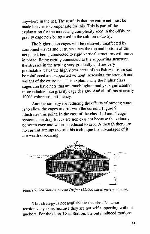
Another strategy for reducing the effects of moving wateris to allow the cages to drift with the current. Figure 9illustrates this point. In the case of the class 1, 3 and 4 cagesystems, the drag forces are non existent because the velocitybetween cage and water is reduced to zero. Although there areno current attempts to use this technique the advantages of itare worth discussing.
Figure 9. Sea Station-Ocean Drifter �5,000 cubic meters volume!.
This strategy is not available to the class 2 anchortensioned systems because they are not self supporting withoutanchors. For the class 3 Sea Station, the only induced motions

are then from its response to waves, which tend to be very Ios'or negligible. Although this strategy sounds idealistic, there areareas, such as the Straits of Juan de Fuca, where the water
motion cycles will allow this tactic and will keep the sea cageswithin a bounded area. In this case, divers could work the
system 24 hours per day because current is no longer a factor,and waves do not affect the cage. In the version shown in thedrawing, it is possible to have a simple diver lock out door wellbeneath the water surface to make diving even easier. Fishwaste would be distributed over a large area for naturaldecomposition and the fish would experience only minimalwater motions. The structural design would be simplifiedbecause the water motion forces will be greatly reduced whencompared to systems that are anchored. The behavior of themodel Sca Station has been investigated under this free driftingmode and it is technically achievable with present technology.
Where Do We Go From Here?
We must concentrate on the class 2 and the class 3 sea
cage designs because gravity cages do not meet any of ourbasic design criteria when applied in opened water. Gravitycage deformations in currents are the culprit. If we insist ontaking Class l gravity cages to oceanic sites, their performancedef'iciencies will he compounded and the development of theindustry will be greatly hindered. These are strong words, butthey can be supported by theory, experience and the growingevidence of operational and environmental problems expresseddaily in our publications. We believe the present stagnant stateof development in the sea farming industry is a direct result ofgravity cage application to sea farming, We believe that everyproblem confronting the gravity cage industry can be solved byusing the higher class sea cages reference 2!. For example,some fish health issues and high stress levels, feed dispersioninefficiencies, operational incfficiencies and predation bymarine mammals can all be traced directly to gravity cageenclosures. And think about this, what other animal besides
farmed fish are raised in gravity cages that continually change

shape, trapping the creatures in fold» of netting, as the growingvolumes approach near zero'.i Can we»ay that we are treatingour final product well".
Since water simulates an anti-gravity environment,stability must be provided by structural rigidity or membranetensions in the netting enclosure. For an example, without astable and firm foundation, the development of machines,instrumentation and techniques for improving sea farming isgreatly hindered. Class 2 through class 4 cages provide thisstable base for sea farming evolution. We need;i betterunderstanding of the advantages of each cage class and itspotential application. To encourage investment anddevelopment, risks mu»t be evaluated based on the higher classsea cage» and not on gravity cages. After studying the sea cagedesigns I'or nearly 10 years, I have come to the conclusion thatgravity cages have no place in the ocean, and there is a growingbody of evidence that they,ire even a poor cage class to u»e atsheltered water sites.
Summation
After attending almost every off»hore sea farmingconference since 1989, we have decided it i» necessary to standup and talk down to the gravity cage mentality, il. is the wrongtechnology for the 'ipplication. The oce;m doe» not grantwishes, it doesn't tolerate the untit. I would like to end with ananalogy describing the gravity cage fixation of our industry.
Imagine that in tiont of u» lie» a large pile of rocks�perhaps IO tons. We a»k that each one of you go out to Itnd avehicle that can haul these rocks away. We will bet that all ofyou will look for a truck and that none of you come back with apassenger car to do the job. The passenger car represents theclass I vehicle and the truck», higher class vehicles. Yes, wecan haul the rocks with the passenger c.ir. but not very well.And yes, we can all cite situations were gravity cages havewith»tood the raging wind, wave and current, but statisticallythey are bound to fail. And yes, wc can modify the passengercar to do the job a bit better, but normal performance of the
143
vehicle and the sea cages must be matched to the job ifstatistically low failure rates and efficient, profitable operationsare our goals. We all know each vehicle class and itscapabilities with hardly a second thought. That is where wehave to be in our understanding of sea cages if offshore seafarming is to become an industry in our lifetime. And higherclass sea cages must be applied in the sheltered wateraquaculture industry if its problems are to be solved and thechallenge of continuing lower salmon prices are to be met. Ifthis sounds too good to be true, it is not. It is the reality of thesituation. Question us, challenge us, the industry needs toaddress these issues.
References
Loverich, G.F., K. Swanson, and L. Gace. 1996. Onshore AquacultureHarvest and Transport Concept; Feasibility and Development.Appendix, Final Report Sea Grant NAS6FD0071.
Morimura, S. 1993. Influences of the Environment on 1'ish Farming. FirstInternational Conference-Fish Farming Technology, Trondheim,Norway. 160 pp.
Slaattelid, O.H. Engineering for Oflshore Fish Farming. 98 pp.
Proceedings of the conference organized by the Institution of Civil Engineers,Glasgow, Scotland, Oct 1990.
144