Embed Size (px)
Citation preview
COMPUTATIONAL FRACTURE MECHANICS FOR COMPOSITES
STATE OF THE ART AND CHALLENGES
Ronald KruegerNIA - Senior Staff Scientist
CAA/FAA Workshop on Adhesive Bonding, Gatwick, UK, October 2004

ACKNOWLEDGEMENTS
T. Kevin O’Brien, ARL/VTD at NASA LaRCJames Reeder, NASA LaRCIsabelle Paris, Composites Innovations Inc. - MontrealJames Ratcliffe, NRC at NASA LaRCPierre Minguet, The Boeing Company - PhiladelphiaD.M. Hoyt, NSE Composite, SeattleGerald Mabson, The Boeing Company - SeattleJeff Schaff, Sikorsky AircraftCatherine Ferrie, Bell Helicopter Textron Inc. - Fort WorthLarry Ilcewicz, FAA - SeattleCurtis Davies, FAA - Atlantic City

OUTLINE
• Delamination sources at geometric and material discontinuities• History of skin-stiffener debonding testing and analysis
• Fracture mechanics methodology for delamination onset prediction• Experiments to determine fracture toughness• Finite element analysis to compute mixed-mode energy release rate
• Past studies on skin/stringer debonding• A shell/3D modeling technique• Application of Fracture Mechanics Methodology
• Summary
• Outlook
• Summary of FAA/ASTM D30 Workshop
• Remaining challenges

DELAMINATION SOURCES AT GEOMETRIC AND MATERIAL DISCONTINUITIES
Skin stiffener interaction
Corner
Solid-sandwich transition
Internal ply drop
Straight free edgeExternal ply drop
InterlaminarStresses
τxz
σzz

HISTORY OF SKIN/STIFFENER DEBONDING PRESSURIZED COMPOSITE FUSELAGE
• Composite Fuselage Technology Development*
Crown panelframe bonded onto skin to
reduce manufacturing costs
Out-of-plane loading dueto pressurization
deformed shape
*L.B. Ilcewicz, Composite Technology Development for Commercial Airframe Structures

HISTORY OF SKIN/STIFFENER DEBONDING POST-BUCKLED THIN-SKIN ROTORCRAFT FUSELAGE
Post-buckling behavior drives weight in thin-skin rotorcraft fuselage
Buckling generates severe stresses on the bondline between skin and stiffeners
Composite fuselage stiffened skin*
V-22 Osprey Tiltrotor aircraft
*Pierre Minguet, Boeing

HISTORY OF SKIN/STIFFENER DEBONDING POST-BUCKLED THIN-SKIN ROTORCRAFT FUSELAGE
Testing of Stiffened Shear Panel Debonding MechanismBoeing, Philadelphia*
Qxy
Mxx
N xx
Failure initiation
SkinFlange
Bondline
Frame or stiffener
Tip of flange
Simplified Specimen
Skin
Stiffener flange
*Pierre Minguet, Boeing
CURRENTLY USED FAILURE METHODOLOGIES
• Stress-Based Failure Criteria• Damage Mechanics
– Decohesion element (interface elements) Carlos Davila, Pedro Camanho, to be implemented in ABAQUS 6.5 released in December 2004
• Linear Elastic Fracture Mechanics– Captures discontinuity of interlaminar disbonds or delaminations– Stress singularities not an issue– Characteristic material data can be generated using simple specimens
and tests

FRACTURE MECHANICS METHODOLOGY
Energy Release Rate
crack opening in plane shear tearingmode I mode II mode III
Failure occurs if local mixed mode energy release rate exceeds a critical value !
G=GI+GII+GIII
G =
dWdA
−dUdA

EXPERIMENTS TO DETERMINE FRACTURE TOUGHNESS
Mode I - DCB Specimen
• ASTM D5528 - static• ASTM D6615 - fatigue
crack openingmode I
Mode II - 4ENF Specimen*
• Standard in development
in plane shear mode II
*Rod Martin, MERL - Barry Davidson, Syracuse University
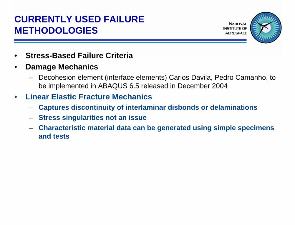
EXPERIMENTS TO DETERMINE FRACTURE TOUGHNESS - continued
Mixed Mode I/II - MMB Specimen*
+
crack opening + in plane shear mode I mode II
• ASTM D6671
*James Reeder, NASA Langley Research Center

2D MIXED MODE FRACTURE CRITERION IS STATE OF THE ART
0 0.2 0.4 0.6 0.8 1Mixed Mode Ratio GII/GT
GC,
J/m2
DCB, Mode I 4ENF, Mode IIMMB, Mode I and II
curve fit

3D MIXED MODE FRACTURE CRITERION IS MISSING TODAY
0
GIII/GT
GIIIc
1.0
GII/GT
GIIc
1.0
GIc
GT
Mode III - ECT Specimen* Failure surface Gc =Gc(GIc, GIIc, GIIIc)**
tearingmode III
• Standard in development*James Ratcliffe,NRC at NASA Langley Research Center **James Reeder, NASA Langley Research Center

STATUS OF FRACTURE TOUGHNESS TESTINGFATIGUE ONSET VALUES
0
50
100
150
200
250
300
350
400
100 101 102 103 104 105 106 107
GImax, J/m2
N, cycles to delamination onset
DCB fatigue datacurve fit to datacurve fit ± one standard deviation
Fatigue Delamination Onset in S2/E7T1 DCB Specimens
GImax=cNd
ASTM Standard D6115
Isabelle Paris, Composites Innovations Inc. - Montreal
Kevin O’Brien, ARL/VTD at NASA LaRC

STATUS OF FRACTURE TOUGHNESS TESTINGFATIGUE PROPAGATION VALUES
Proposed Fatigue Delamination Growth Characterization: Normalizing by the Static R-Curve*
GR a
aStatic delamination R-curve
N
da/dN
dadN
= AGmax a( )GR a( )
⎛
⎝ ⎜ ⎜
⎞
⎠ ⎟ ⎟
n
Gmax/GR*Isabelle Paris, Kevin O’Brien, Rod Martin

ANALYSIS TOOLSOVERVIEW
Analytical Closed Form Solutions for Simple ConfigurationsEdge delamination - Kevin O’Brien
SUBLAM– Georgia Tech, Erian Armanios
– Developed by Material Science Corporation under SBIR contract with the FAA for use with General Aviation bonded joints - Gerald Flanagan
– Can be used to calculate SERR as a function of disbond length
Single-Step SERR Calculation
Bonded Joint Crack Propagation
Co-Cured Structural Elements Curved Beam
Shear Loading Tapered Elements
Closed-form solutions for complex geometries
z
Concentrated lineforce T3
Distributedtractions p(y)
w+
w-
1
2
y, n

ANALYSIS TOOLSOVERVIEW - continued
“Crack Tip Element” - Barry Davidson – Closed-form linear-elastic solution aimed at overcoming computational
difficulties in determining strain energy release rate and mode mix.– Obviates need for locally detailed 2D and 3D FEMs– Limited to linear analysis
Post-buckled delaminations

ANALYSIS TOOLSVIRTUAL CRACK CLOSURE TECHNIQUE (VCCT)
Virtual Crack Closure Technique (VCCT)– Two and three-dimensional analysis
– Nonlinear analysis
– Arbitrarily shaped delamination front
GI = 12∆a
⋅ ′ Y ⋅ ∆ ′ v
GII = 12∆a
⋅ ′ X ⋅ ∆ ′ u
GT = GI + GII
∆a∆a
∆v’∆u’
Y’
X’
y’ ,v’,Y’
x’ ,u’,X’
undeformed outline
deformed elements

ANALYSIS TOOLSBoeing 2D VCCT Interface Element - Formulation
• Interface Element for Mixed Mode Fracture Analysis*
Fv,2,5 crit
Node numbers are shown
t=0
6 5 4
1 2 3
dL dR
x,u
y,v
• Node pair 2,5 are initially bound together• Node pairs 1,6 and 3,4 are unconstrained
and act to sense approaching crack
Nodes 2 and 5 will start to release when:12
v1,6Fv,2,5bdL
= GI ≥ GIC
GI = mode I energy release rateGIC = Critical mode I energy release rate
Mode II treatedsimilarly
Fv,2,5
LoadPure Mode I
V2,5 crit
V2,5
Area = GICdRbModified VCCT
2,5 3,46
v1,6
1 Displacement
x,u
y,vNode numbersare shown
* G. Mabson, Boeing, Patent Pending

ANALYSIS TOOLSBoeing 2D VCCT Interface Element - Propagation
• Fracture Interface Elements Along Crack Plane*
• By using a series of overlapping interface elements, delaminations can be propagated along a predefined path.
• Direction of propagation is not pre-specified.
• Propagation is integral part of the analysis.
• 3D VCCT interface element for delamination available.
• ABAQUS implementation expected for December 2004.
Fracture mechanics interfaceelements control growth ofdelamination into new material
Interface Elements locatedalong plane of delamination
* G. Mabson, Boeing, Patent Pending