Embed Size (px)
Citation preview
Computation of Primary Tunnel Support
LIDIJA FRGI�, MARKO HRANILOVI�* AND KREŠIMIR TOR Faculty of Mining, Geology and Petroleum Engineering)
University of Zagreb Pierottijeva 6, HR-10000 Zagreb
CROATIA http://www.rgn.hr
* Civil Engineering Institute of Croatia
*J. Rakuše 1, HR-10000 Zagreb * http://www.igh.hr
Abstract: - The computation of stress and strain conditions for tunnel profile excavation is performed by the Boundary Element Method (BEM). It is a numerical method performed in geotechnics for resolving of the stress and strain distribution in a rock massif where the change of stress condition occurs during some operations. The method is timesaving procedure for the problem definition in design process, it offers flexibility in assumptions on input parameters characterising the massif, and in observing the influence of changes on the stress and strain conditions. A computer programme has been developed for the purpose. This programme facilitates computation to the influence of different primary support systems on the stress and strain condition. In this paper, the stress and strain conditions for a tunnel profile excavation are compared with the stress and strain conditions for shotcrete lining supported excavation profile. Analogously to the treatment of reinforced concrete, the ultimate bearing capacity of the concrete and steel are considered. The flexibility of the primary support structure is important. The shotcrete lining shall be slender in order to avoid bending moments. Key-Words: Tunnel, Primary support, Bearing capacity, Rock mass, Boundary element method 1 Introduction The most important tunnel excavation method is the New Austrian Tunnel Method (NATM). The method is highly adaptable to daily changes in geologic conditions on the excavation face when the primary support is used with simultaneous monitoring of rock mass deformations.
The whole tunnel profile can be opened in the rock mass at the same time. The tunnel excavation changes the primary state of stresses σv
o and σh
o into a considerably more unsuitable secondary state of stresses σv and σh. Vertical and horizontal stresses (σv
°, σh
°)
depend on the depth under the field surface. Stress condition in the tunnel opening surrounding
depends on the mass´s own weight and on direct loading of the opening boundary with the forces occurring due to the action of the primary supporting system. The primary stresses in the rock mass in the vicinity of the opening decrease with increase in convergence. In most cases some initial rock mass convergence before the primary support is placed is desirable because it results is some relaxation of stresses in the rock mass. When the rock mass mechanical characteristics are known from the in situ measurement results, the initial convergence, support stiffness and time-dependant increase in stiffness and support plasticity is relevant for the stresses in the
support. The NATM represents a method, in which the
surrounding geological formation is included into supporting ring-shaped structure. To simplify, this means that the rock itself becomes a part of the supporting construction. “The bearing rock arch” implies the zones round the tunnel in which most of the time-depending processes of stress distribution occur. “The rock arch activating” implies the treatments by which rock bearing force is maintained or increased in order to exploit this bearing force and to influence the proper development of the stress secondary state σv and σh. The arch effect results in decrease in tensile stresses caused by bending and increase in compressive stresses which are more readily accepted by the shotcrete lining and the rock mass. By its good adhesion to the rock mass, the primary shotcrete support creates the protective lining, which prevents falling of rock mass blocks from the larger and deeper cracks (discontinuities). Continuous monitoring of the rock mass enables fast protection of tunnel top heading and sidewalls, so that plastic and viscous deformations of the rock mass are reduced to minimum. The support must be deformable, but still has to firmly adhere to the excavation edge interacting with the underground rock mass. This firm bond increases mechanical characteristics in the excavation
Proceedings of the 5th WSEAS/IASME Int. Conf. on SYSTEMS THEORY and SCIENTIFIC COMPUTATION, Malta, September 15-17, 2005 (pp278-282)
surroundings and creates protection against the rock mass cracking which could cause loosening and discontinuities in the excavation edge in the rock mass depth direction, namely the bond stabilizes the rock mass, which assumes the supporting role. The primary support made of shotcrete of a given thickness applied immediately after excavation of the underground room forms a shell that bonds all the rough parts of the excavation edge with corresponding surface cracks into a compact unit. 2 Failure criterion For computation of stresses and strains around a tunnel opening supported by primary support, a computer programme has been developed. Hoek-Brown´s programme as a basic tool used for computation of stresses and strains around tunnel opening, developed on the principles of the Boundary Element Method (BEM) for the state of plane strains [2, 3]. The most general form of the Hoek-Brown criterion which incorporates both the original and the modified [9, 10] form is given by the equation
a
c
3bc31 s�
�m�� � ��
�
����
�+⋅+= (1)
Where: σ1 and σ3 – the axial and confirming principal stresses
respectively σc – uniaxial compressive strength of the intact
rock pieces mb – value of the constant m for the rock mass s and a – constans which depend upon the
characteristic of the rock mass. Coefficient a is usually equal 1/2.
This relationship of stress conditions for failure of intact rock graphically is represented in Fig. 1.
Fig. 1 Hoek-Brown failure criterion
3 Computation of stress condition The computation of the influences of primary support systems on the state of stresses and strains around tunnel opening have been added to the main programme.
The elements of the primary support systems in computation could be included, for example bolts, shotcrete lining, reinforced shotcrete lining and steel arches.
A rock-support system is a statically undefined system. The problem is complex, and it is difficult to define the real interaction between the rock mass and primary support, because the shotcrete and reinforced shotcrete of the support begin to function during hardening.
The ultimate state of stresses and strains has been adopted as a basic for the primary support computation. The rock deformations (convergation) will progress until collapsing of the support in ultimate state. This situation corresponds to the case C in the Eurocode 7 – Geotechnics [5].
Therefore, the ultimate reactive support forces need to be included and the rock properties decreased by the safety coefficient. An alternative is to use the conditions of the case B, with real rock properties and the reactive support pressures decreased by the safety coefficient for standing forces.
As an introduction into the stress and strain analysis of the primary support carrying capacity, the Eurocode 2 [4] and Eurocode 7 will be used which define the method for proving stability of concrete and geotechnical structures. The limit state of action Sd (design values of actions) must be less or equal to the ultimate limit state (design resistance) of a structure Rd:
dd RS ≤ (2)
The bolts are the elements of the primary support.
The bolt action is defined by two equal opposite forces, one on the boundary of the opening and the other in the mass (Fig. 2). Bearing capacity of the bolt Sb is ultimate force
m
ykbb
�
fA� S
⋅⋅= (3)
Where: Αb – area of the bolt cross-section (m2) fyk – yield stress of steel (kN/m2) γ – partial safety factor for the action γm – partial safety factor for material property (steel).
In the programme, the length of bolt L and direction angle ϕ need to be defined.
The support with the shotcrete lining is placed along the curved boundary of the opening (Fig. 2 - Detail A).
Proceedings of the 5th WSEAS/IASME Int. Conf. on SYSTEMS THEORY and SCIENTIFIC COMPUTATION, Malta, September 15-17, 2005 (pp278-282)

The shotcrete layer is an essential element of the primary support and the ultimate bearing capacity is
1m
ck
�
0.1df�� N
⋅⋅⋅⋅= (4)
Where: α − coefficient fck – compressive strength of shotcrete (kN/m2) d – thickness of shotcrete lining (m) γm1 – partial safety factor for material property
(shotcrete).
Fig. 2 Interaction of primary support and rock mass
The unfavourable effect of a long-term loading and dynamics effects are taken into the account with coefficient α.
The internal loading of the tunnel opening causes reactive pressure of the primary support. The reactive pressure of a chosen system has to keep the rock in stable equilibrium. Rock deformations are increasing until the state of stresses in the rock and reactive pressure of the support are in equilibrium. The created equilibrium prevents further rock mass movements and makes it stable.
The primary support arch made of shotcrete has normally no bending moments, because the loading occurs during hardening process when the concrete has great relaxation and adaptation possibilities. As a structural element the primary support arch is usually relatively thin so it can be treated as a shell without bending.
The loading of the support arch increases gradually and the definite state occurs when the shotcrete reaches the final stiffness. The young shotcrete is very ductile, so an uniform distribution of stresses including the normal force in the support arch is not far from reality. The relation between the thickness of the shotcrete lining and radius is the same as in very thin structures that are treated as shells, where the influence of bending is usually completely neglected.
Similar to schemes of stress distribution in plastified cross-sections of reinforced beams, an idealised stress distribution in the shotcrete cross-section can be assumed. The linear diagram of the strains has as result the parabolic diagram of the stresses.
If the influence of bending is neglected, the pressure on the arch surface ps will be
RN
p s = (5)
Where: R – radius of support arch (m).
Assuming the ultimate parabolic form of stress diagram the ultimate reactive pressure of the shotcrete support arch is
0.1d�
f��
32
R1
p1m
cks ⋅⋅
⋅⋅⋅⋅= (6)
The ultimate bearing capacity of the reinforced
shotcrete lining is
���
����
� ⋅+⋅⋅⋅⋅=
m
yk
1m
ck
�
Af
�
0.1df�� N (7)
Where: A – cross-section of wire mesh for one meter of the
tunnel (m2/m).
The bearing capacity of steel arches support can be calculated in the same way
e�
fA� N
m
ykaa ⋅
⋅⋅= (8)
Where: A – cross-section of steel arches (m2). e – distance between arches (m).
The stress and strain analysis for the area by the tunnel opening is conducted by the boundary elements method [11]. The boundary element program for two-dimensional stress displacement and failure analysis, assumed from E. Hoek and E. Z. Brown was upgraded by specifying ultimate carrying capacities for the support elements [12, 15, 16]. Pretprocessor with interactive input and postprocessor for graphic presentation of the results have been added to the program. In the main program the influences of various support systems for underground rooms were added especially: shotcrete layers, steel arches and rock bolts. The BEM is faster than other numerical method and represents an efficient supplementation to them. The input data include tunnel opening geometry, properties of the rock mass, and loads. The opening edge is segmented into strength sections or circle/ellipse sections. The boundary elements method is time-saving when it comes to
Proceedings of the 5th WSEAS/IASME Int. Conf. on SYSTEMS THEORY and SCIENTIFIC COMPUTATION, Malta, September 15-17, 2005 (pp278-282)
specifying i.e. defining the problem during a design process, flexibility in setting input parameters characteristic for the underground rock mass and observing effect their changes have on the stress and strain states.
This method is also adopted by the International Tunnelling Association (ITA) guidelines [13] as equal to the finite elements method and finite differences method for use in computations.
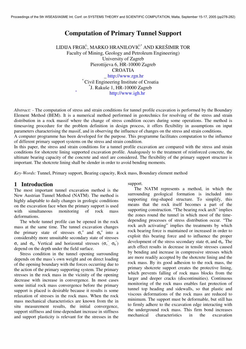
The boundary element method with Hoek-Brown`s failure criteria was used in computations for a road tunnel case.
The diagram of circular stress σ� along the opening boundary is shown in Fig. 3 for the case the of reinforced shotcrete lining as the primary support (20 cm thick layer of shotcrete with wire meshes Q-257). It shows stress concentrations in the corner of a profile. That could cause certain plastification.
Fig. 3 Diagram of normal circular stresses σ�
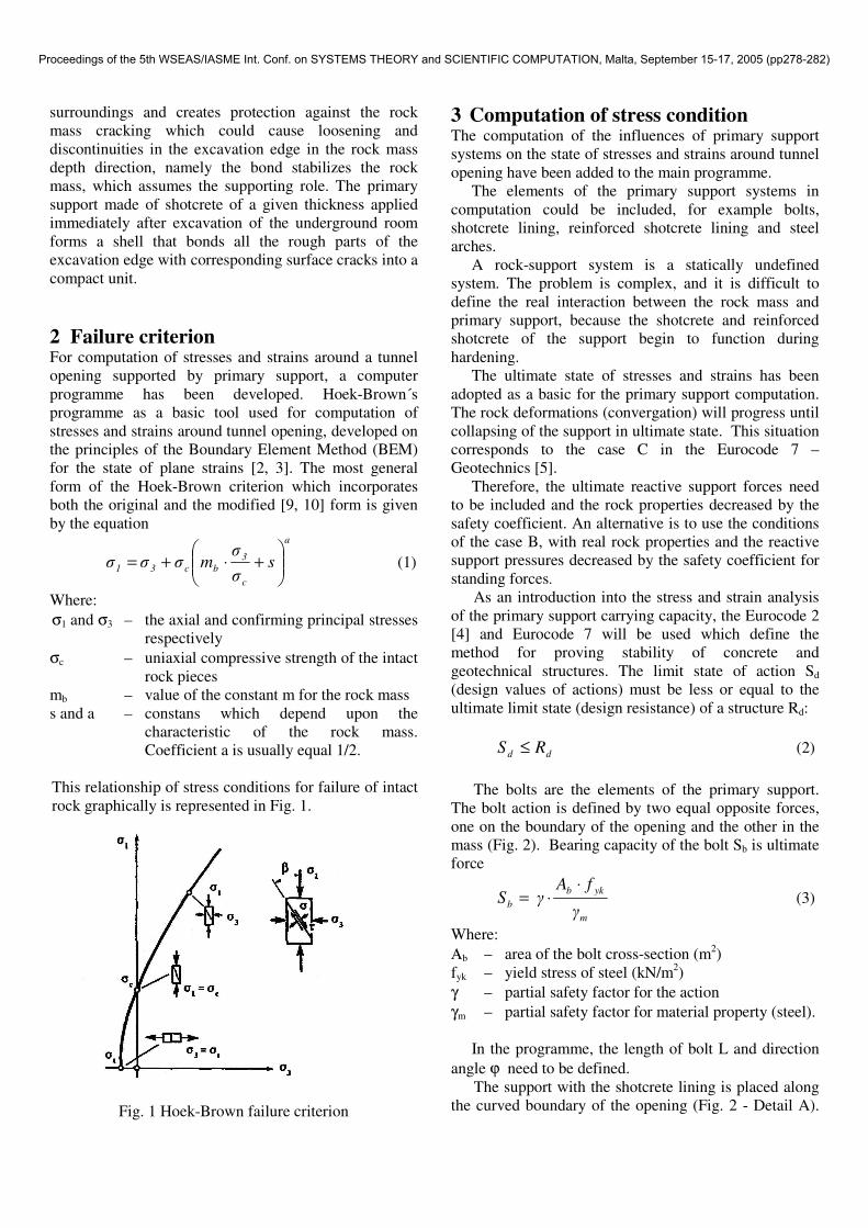
The Fig. 4 represents the relation between the critical
circular stress σcr and the actual stress� σ� as the safety coefficient for so supported profile. Doted line marks ratio of 1.0 of these stresses.
Fig. 4 Diagram of safety coefficients along the opening
boundary support by shotcrete lining
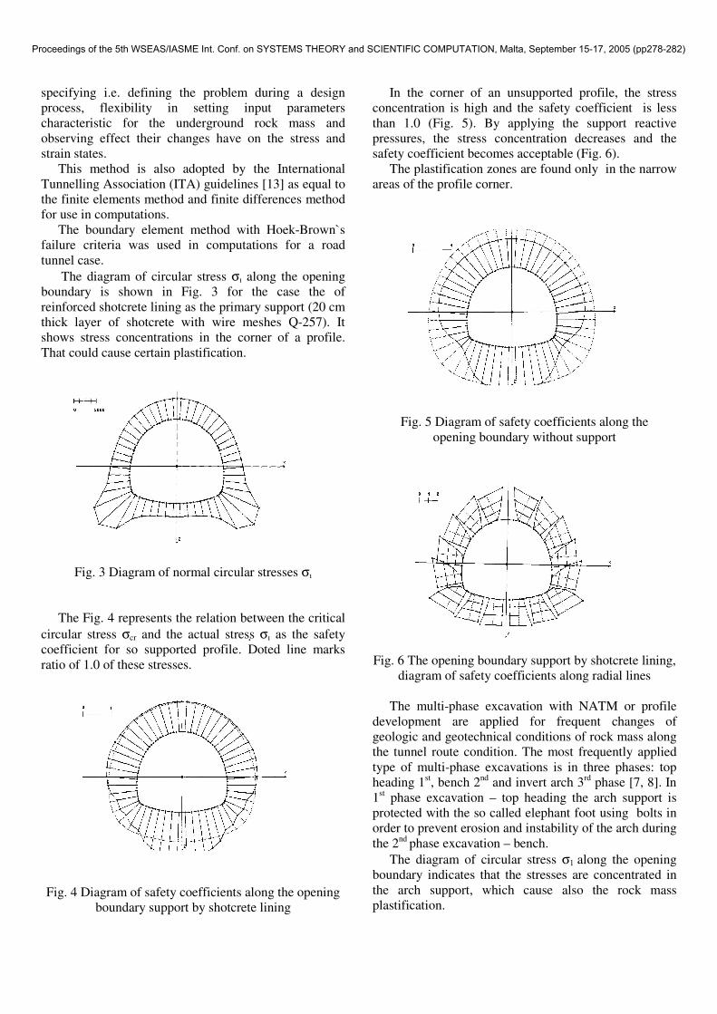
In the corner of an unsupported profile, the stress concentration is high and the safety coefficient is less than 1.0 (Fig. 5). By applying the support reactive pressures, the stress concentration decreases and the safety coefficient becomes acceptable (Fig. 6).
The plastification zones are found only in the narrow areas of the profile corner.
Fig. 5 Diagram of safety coefficients along the opening boundary without support
Fig. 6 The opening boundary support by shotcrete lining,
diagram of safety coefficients along radial lines
The multi-phase excavation with NATM or profile development are applied for frequent changes of geologic and geotechnical conditions of rock mass along the tunnel route condition. The most frequently applied type of multi-phase excavations is in three phases: top heading 1st, bench 2nd and invert arch 3rd phase [7, 8]. In 1st phase excavation – top heading the arch support is protected with the so called elephant foot using bolts in order to prevent erosion and instability of the arch during the 2nd phase excavation – bench.
The diagram of circular stress σ1 along the opening boundary indicates that the stresses are concentrated in the arch support, which cause also the rock mass plastification.
Proceedings of the 5th WSEAS/IASME Int. Conf. on SYSTEMS THEORY and SCIENTIFIC COMPUTATION, Malta, September 15-17, 2005 (pp278-282)
4 Conclusion The stress and strain analysis and foreseeing of the rock mass behaviour during tunnel excavation is a complex engineering problem.
For a design process, it is important to evaluate the stability conditions in excavation and after the acceptance of suitable breaking out methods, the acceptance of supporting in order to stabilise the opening.
The computation was done of the stress condition in whole profile excavation supported with the shotcrete layer due to the essential impact on the stress and strain condition near the tunnel openings. After the excavation, the supporting system is placed causing loading of an opening boundary with the reactive support pressure on rock e.g. shotcrete lining, bolts and steel arches.
The essential problem is to assume and estimate the possible ultimate reactions depending on tre form of opening, dimensions and properties of the suuport and performances of the structural static system.
To estimate the stability conditions near the excavation circular stresses σ1 along the contour are compared.
This paper represents the continuation of many years of research, design and development of software at the Faculty of Mining, Geology and Petroleum Engineering. References: [1] Bieniawski, Z.T., Rock Mechanics Design in Mining
and Tunnelling, Wiley, Rotterdam, 1984 [2] Brebia, C. A., Boundary Elements, an introductory
course, Tempus – ACEM, Maribor, 1992 [3] Brebia, C. A.; Dominguez, J., Boundary Elements,
Mc. Graw Hill, London, 1992 [4] Eurocode No. 2 Design of Concrete Structures,
Commission of the European Communities, 1990 [5] Eurocode No. 7 Geotechnics, Commission of the
European Communities, 1989 [6] Frgi�, L., Tor, K., Jaguljnjak-Lazarevi�, A., Stress
Analysis in Homogeneous Medium During Tunnel Excavation, Proceedings of the 3rd International Congress of Croatian Society of Mechanics, Cavtat, Croatia, 2000, pp. 201-208
[7] Frgi�, L., Tor, K., Jaguljnjak-Lazarevi�, A., Comparison of Stresses in Multi-phase Excavations by the New Austrian Tunnel Method, Proceedings of 6th Symposium on Tunnel Construction and Under-ground Structures, Ljubljana, Slovenia, 2002, pp. 28-36
[8] Frgi�, L., Tor, K., Hrestak, T., Stresses in Multy-phase Excavations of Tunnel, The Mining-Geological-Petroleum Engineering Bulletin, Zagreb, Vol. 15, 2003 pp. 63-70 (in Croatian)
[9] Hoek, E., Kaiser, P.K., Bawden; W.F. Support of
Underground Excavations in Hard Rock, Balkema, Rotterdam, 215 pp. 1997
[10] Hoek, E.: Rock Engineering, course notes, Internet, Vancouver, 1999
[11] Hudec, M.; Frgi�, L. Boundary Element Method, The Mining-Geological-Petroleum Engineering Bulletin, Zagreb, Vol. 5, Zagreb, 1993, pp. 109-118 (in Croatian)
[12] Hudec, M., Frgi�, L., Tor, K., The ultimate state concept applied to tunnel support, The Mining-Geological-Petroleum Engineering Bulletin, Vol. 12, Zagreb, 2000, pp. 67-75 (in Croatian)
[13International Tunnelling Association ITA, Guidelines for the Design of Tunnels, Pergamon Press PLC, G. Britain,1988
[14] Tor, K., Frgi�, L., Jaguljnjak-Lazarevi�, A., Stress and strain analysis around underground room, The Mining-Geological-Petroleum Engineering Bulletin, Zagreb, Vol. 12, 2000, pp. 59-66 (in Croatian)
[15] Tor, K., Jaguljnjak-Lazarevi�, A., Frgi�, L., The Influence of the Primary Support in Tunnel Design, Proceedings CD-ROM of the 1st International Conference "From Scientific Computing to Computational Engineering, Patras Grece, 2004, 1-7
[16] Tor K., Frgi�, L., Jaguljnjak-Lazarevi�, A., Another Way to Compute the Underground Room Support, Proceedings CD-ROM of the 6th World Conference of Computational Mechanics, Beijing Chine, 2004, pp. 1-10
Proceedings of the 5th WSEAS/IASME Int. Conf. on SYSTEMS THEORY and SCIENTIFIC COMPUTATION, Malta, September 15-17, 2005 (pp278-282)