Embed Size (px)
Citation preview

HINTS FOR HOMEBUILDERS . ; : • .<• ; , or,'1!'rrs KB 3v•'-.•?. ;•
COMPRESSION TESTER- . . .KJ , ; - : . B Y EDSEL FORD, J R , . O'Jll.
Differential compression tester is atool used for everyday engine mainte-nance and inspection. So how do theywork? Is it smoke and mirrors or arethe roots based deeper in Physics? Ac-tually, the roots are Physical in nature.When studying gas laws, one finds thatpressure dropped across a fixed orificewill be an indication of flow rate. Thegreater the difference of the pressurechange, the higher the flow. When youhear someone quote compression fig-ures such as 75 over 80 or 55 over 80,the person is talking about cylinderleak rate; and the 75 over 80 is a lowerleak rate than the 55 over 80. There isnothing magic about the number of 80as a reference pressure. The cylindertest pressure and the orifice size isstated in A.C. 43.13, Acceptable Meth-ods, Techniques, and Practices ofAircraft Inspection and Repair, Change3, Chapter 14, Section 1, page 272,paragraph 692. In fact, this includes anice schematic of the tester and the ori-fices to be constructed and used. As anexample, for engines under 1000 cubicinches, you would use a .040 inch ori-fice; and on engines over 1000 cubicinches, you would use a .060 inch ori-fice. The largest Pratt & Whitneyengine I have used the .040 orifice withis the R-985; for the Pratt & WhitneyR-1340 I would use the .060 orifice.
I wonder how many 1340 ownershave overhauled cylinders because thetester was the wrong size? The .040orifice will give a bigger leak indica-tion than would be normal for thatsize engine. Normally, homebuildersuse engines of under the 1000 cu. in.size such as the Lycoming O-360 orthe Continental O-470. The bigger en-gine operators could be buying morecylinders than needed and smaller en-gine operators may be flying anengine with excessive leakage if the.040 and .060 sizes are used on thewrong size engine.
The tester that is included in the fol-lowing drawings is dimensioned for106 JULY 1996
ease of construction. The only criticalsizes are the orifice size length and ap-proach angle. Also, the workingpressures of the regulator and gageshave been chosen to give a wider scaleto allow easier reading. If you followthe drawings, you will produce a veryfunctional tester that also looks good. If
you are like me, you have a lot of thesupplies already (JUNK). You need tomatch the orifice size and shape; thenincorporate the things you already have.You will save more money and, finally,use some of the stuff that just lookedtoo good to pass up or throw away.
The heart and soul of the tester (Figure
FIGURE 1
DRILL * TAP1/4" NPT
L—— DRILL* TAP 1/8" NPT ORIFICE 1/4" LONG.040" DIA. 160 DRILL
0-IOOpsi.GAGE
FIGURE 2
1/8 MALE MALERPE COUPLING
L 1/4 MALE FITTINGTO FIT SHOP AIR
CYLINDERCONNECRTORSEE DETAIL
COMPRESSIONTEST BLOCKPER DRAWING
AIR HOSE 3' T04'1/4 MALE PIPE ENDS
AIR LINE QUICK CONNECT
1) is a piece of aluminum 1" x 1" x 2" (arefugee from the scrap barrel). The holeswere sized to fit the common mini regula-tors. The common regulator has 4 ports —2 are 1/4 pipe, and 2 are 1/8 pipe. Gagesare easier to find with 1/4 pipe fittingsand saves you from having to find differ-ent gages with identical scales. The 1/4pipe air fitting is the most common type.
The .040 x .250 inch orifice is shownsince this is the most common size enginefor the homebuilder. If you are going totest the larger engines, the hole needs tobe .060 x .250 inch (same length, just abigger hole). The 60° approach angle maylook exotic but if you will study a nor-mally ground drill bit you will find it willbe ground to a 59° angle. Given normaltolerances, ±1° will work.
The system is laid out in Figure 2.One suggestion that I might add (notincluded on the drawing) is the incor-poration of a 90° valve between theblock and cylinder hose to make thetool easier to use. During assemblyyou might use thread sealer or Teflon™tape. A word of caut ion — be ex-tremely careful of any stray sealer ortape that might make its way into anypassage. This could make the tester in-accurate or introduce foreign objectsinto the cylinder. If you want to checkthe tester against specifications, Tele-dyne Continental Service Bul le t inM84-15 states, "A properly calibratedtester with a .040 orifice should flow120±5 cubic feet per hour at 30 psiwith a regulated pressure of 80 psi."
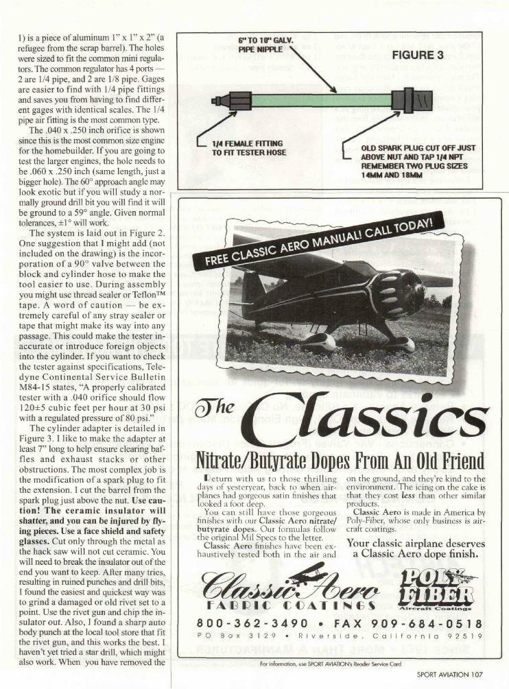
The cylinder adapter is detailed inFigure 3. I like to make the adapter atleast 7" long to help ensure clearing baf-fles and exhaust stacks or otherobstructions. The most complex job isthe modification of a spark plug to fitthe extension. I cut the barrel from thespark plug just above the nut. Use cau-tion! The ceramic insulator wil lshatter, and you can be injured by fly-ing pieces. Use a face shield and safetyglasses. Cut only through the metal asthe hack saw will not cut ceramic. Youwill need to break the insulator out of theend you want to keep. After many tries,resulting in ruined punches and drill bits,I found the easiest and quickest way wasto grind a damaged or old rivet set to apoint. Use the rivet gun and chip the in-sulator out. Also, I found a sharp autobody punch at the local tool store that fitthe rivet gun, and this works the best. Ihaven't yet tried a star drill, which mightalso work. When you have removed the
6"T010"GALV.PIPE NIPPLE FIGURE 3
1/4 FEMALE FITTINGTO FIT TESTER HOSE OLD SPARK PLUG CUT OFF JUST
ABOVE NUT AND TAP 1/4 NPTREMEMBER TWO PLUG SIZES14MMAND18MM
^ CfassicsNitrate/Butyrate Dopes From An Old Friend
L'eturn with us to those thr i l l ingdays of yesteryear, hack to when air-planes had gorgeous satin finishes thatlooked a foot deep.
You can still have those gorgeousfinishes with our Classic Aero nitrate/butyrate dopes. Our formulas followthe original Mil Specs to the letter.
Classic Aero finishes have been ex-haustively tested both in the air and
on the ground, and they're kind to theenvironment. The icing on the cake isthat they cost less than other similarproducts.
Classic Aero is made in America byPoly-Fiber, whose only business is air-craft coatings. t«Your classic airplane deserves
a Classic Aero dope finish.
PA E R I C CC/tl* I NeS8 0 0 - 3 6 2 - 3 4 9 0 • F A X 9 0 9 - 6 8 4 - 0 5 1 8P O B o x 3 1 2 9 • R i v e r s i d e , C a l i f o r n i a 9 2 5 1 9
For information, use SPORT AVIATION'S Reader Service Card
SPORT AVIATION 107

insulator and remaining junk in the endof the plug, drill and tap 1/4 npt to ac-cept the nipple. Remember that there aretwo sizes of plugs in aircraft engines.The most common is 18mm and 14mmwhich is less common. If you are run-ning a converted auto engine or otherpowerplant that uses a spark plug of adifferent size, then use a plug from thatengine. I use a new copper spark plugwasher or a Teflon™ hydraulic seal forthe adapter to cylinder seal. The O-ringssometimes used seem to work out fromunder the adapter and cause leaks.
Following is a list of materials tocomplete the project as drawn.
1 ea. aluminum block 1" x 1" x 2"1 ea. mini air regulator 0-100 psi
working pressure2 ea. gages 2" 0-100 psi 1/4" npt con-
nection2 ea. 1/4" male barbed hose connector2 ea. hose clamps1 ea. air connector 1/4" npt male1 ea. air connector 1/4" npt female1 ea. coupler 1/8" male pipe to 1/8"
male pipe1 ea. 1/4" x 6" pipe nipple
1 ea. 4' air hose 1/4" dia.1 ea. air hose quick connect1 ea. 90° on/off valve 1/4" male to
1/4" female pipe (optional valve)
(This hint was sumitted by Edsel Ford,Jr., EAA 87466, 11613 S. LinnAve.,Oklahoma City, OK 73170-2642.)
FLUKE.
Readers are invited to submit entries to EAA's Hints For Homebuilders, Att: Golda Cox, P.O. Box3086, Oshkosh, WI 54903-3086. Entries will be reviewed by a panel of EAA judges. Readerswhose hints are published in SPORT AVIATION will be awarded a 7-piece Combination WrenchSet from Snap-on Tools, a $25 gift certificate plus a current catalog from Aircraft Spruce & Spe-cialty, a Lenox 4012 Hacksaw Frame from American Saw & Mfg. Co. and a Pro 360 DigitalProtractor from Macklanburg-Duncan. Members are also invited to submit hints of an electrical na-ture. Any hint used will receive a Fluke Model 23-2 Multimeter with Holster from the John FlukeMfg. Co., Inc. The contest will run from August through July of each year with a Grand Prize beingpresented by Snap-on Tools, Aircraft Spruce & Specialty ($250 gift certificate), American Saw &Mfg. Co. (Lenox VBKMA-6 Van-Bit Kit) and Macklanburg-Duncan ($250 cash). A Grand Prizewill also be awarded by the John Fluke Mfg. Co. These awards will be presented during the EAAConvention. Our thanks go to our sponsors for these awards.
VACUUM BAGGING & COMPOSITE TOOLING MATERIALSVacuum Bagging,Films to eliminate voidsEmbosslon - Embossed nylon for quick air evacuation & UV curing resins.Peel-Plies to eliminate sandingRelease Agents - No Silicone, No CFC's, Low VOC's, Air dryRelease Films - Low Cost, High Elongation, Many perforations to choose fromSealant Tapes and BreathersConnections - Vac Valves (Frogs!) Quick Disconnect & Vacuum HoseRepair Kits - Small quantity Kit of Vacuum Bagging materialsEpoxy and Polyester Quick Setting Filler Pastes and Putties
LOW TEMPERATURE RE-USABLECURING PREPREGS SILICONE RUBBER
• 140°F(55°C) Curing Graphiteor Fiberglass Structural Prepregs
• 140°F (55°C) Curing Prepregs for Tooling
AIRTF.CHINTERNATIONAL INC.2542 East Del Amo BoulevardPost Office Box 6207Carson, California 90749-6207(310) 603-9683 FAX: (310) 603-9040 INTERNET
http://www.airtechintl.com
SINCE 1973 • MORE THAN A MANUFACTURER
• Custom Pre-fit Vacuum Bags• Clear Rubber Available to Assist
U.V. Curing Resins
AIRTF.CHEUROPE S.A.Zone Industrielle HaneboeschL-4562 Differdange , , j a-.•..<,LUXEMBOURG(352) 582282 FAX: (352) 584935
A TECHNICAL PARTNERFor information, use SPORT AVIATION'S Reader Service Card
108 JULY 1996