Embed Size (px)
Citation preview
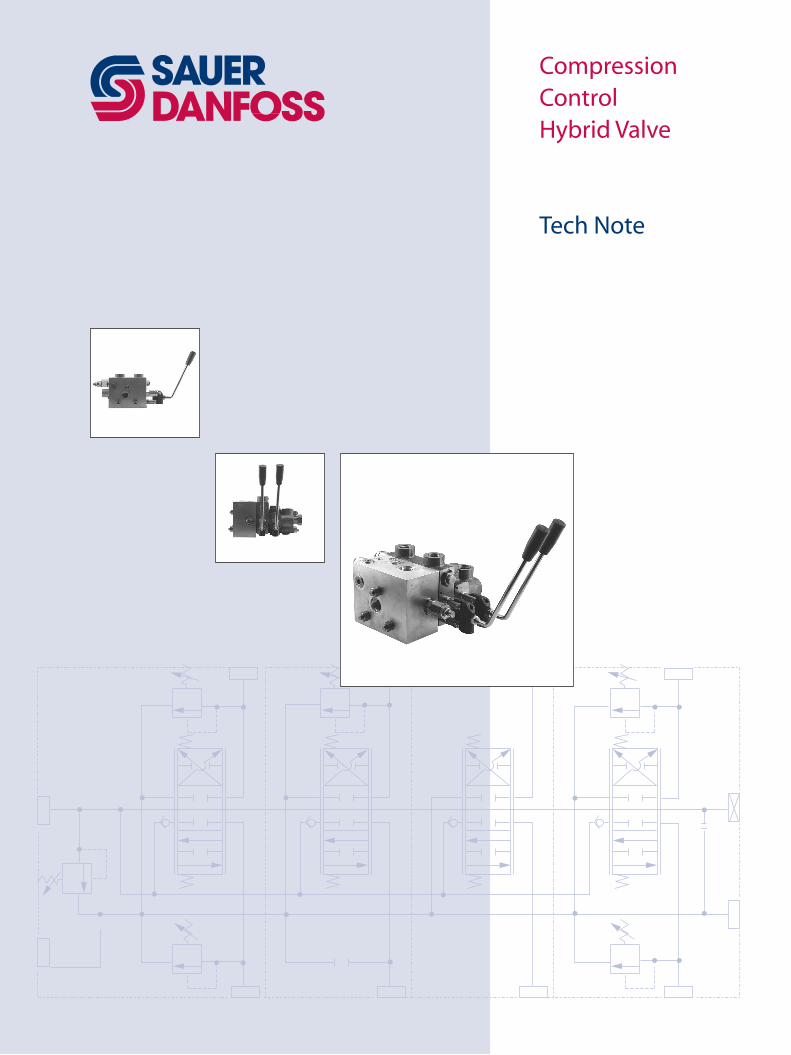
Compression Control Hybrid Valve
Tech Note
� 110��635 • Revision AA • May 2007
Compression Control Hybrid ValveTech Note
© 2007 Sauer-Danfoss. All rights reserved.
Sauer-Danfoss accepts no responsibility for possible errors in catalogs, brochures and other printed material. Sauer-Danfoss reserves the right to alter its products without prior notice. This also applies to products already ordered provided that such alterations aren’t in conflict with agreed specifications. All trademarks in this material are properties of their respective owners. Sauer-Danfoss and the Sauer-Danfoss logotype are trademarks of the Sauer-Danfoss Group.
Revisions
Table of RevisionsDate Page Changed Rev.
May 2007 - First edition AA
HistoRy of Revisions
3110��635 • Revision AA • May 2007
Compression Control Hybrid ValveTech NoteContents
GeneRal DesCRiPtion
system DesiGn PaRameteRs
teCHniCal sPeCifiCations
moDel CoDe
installation DRawinGs
sCHematiCs
Overview ........................................................................................................................................................... 4Typical applications ....................................................................................................................................... 4Standard features ........................................................................................................................................... 4
Fluids ................................................................................................................................................................... 5Filtration............................................................................................................................................................. 5
Base stock and additives ........................................................................................................................ 5Viscosity........................................................................................................................................................ 5For more information .............................................................................................................................. 5Return line filtration ................................................................................................................................. 5Cleanliness................................................................................................................................................... 5
Specifications ................................................................................................................................................... 6Typical performance ..................................................................................................................................... 6
HIC inlet or outlet ........................................................................................................................................... 7Truck Schematic .............................................................................................................................................. 7Max load telescopic section ....................................................................................................................... 8
Dimensions Inlet Hybrid Valve - 11027345 ........................................................................................... 9Dimensions Outlet Hybrid Valve - 11027346 .....................................................................................10
Compression Control Hybrid Valve Schematics ................................................................................11
� 110��635 • Revision AA • May 2007
Compression Control Hybrid ValveTech NoteGeneral Description
tyPiCal aPPliCations
ComPRession ContRol HybRiD valve
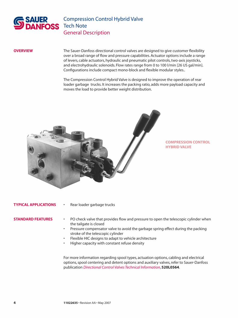
oveRview The Sauer-Danfoss directional control valves are designed to give customer flexibility over a broad range of flow and pressure capabilities. Actuator options include a range of levers, cable actuators, hydraulic and pneumatic pilot controls, two-axis joysticks, and electrohydraulic solenoids. Flow rates range from 0 to 100 l/min [26 US gal/min]. Configurations include compact mono-block and flexible modular styles..
The Compression Control Hybrid Valve is designed to improve the operation of rear loader garbage trucks. It increases the packing ratio, adds more payload capacity and moves the load to provide better weight distribution.
• Rear loader garbage trucks
stanDaRD featuRes • PO check valve that provides flow and pressure to open the telescopic cylinder when the tailgate is closed
• Pressure compensator valve to avoid the garbage spring effect during the packing stroke of the telescopic cylinder
• Flexible HIC designs to adapt to vehicle architecture• Higher capacity with constant refuse density
For more information regarding spool types, actuation options, cabling and electrical options, spool centering and detent options and auxiliary valves, refer to Sauer-Danfoss publication Directional Control Valves Technical Information, 5�0l056�.
5110��635 • Revision AA • May 2007
Compression Control Hybrid ValveTech NoteSystem Design Parameters
filtRation Effective filtration is critical to a hydraulic system’s performance and working life. Employ system filtration capable of meeting the published requirements in each valve section. Be aware that other components in the system may have more stringent requirements. Design your filtration system to satisfy the requirements of the most sensitive component.
Return line filtrationReturn line filtration is generally adequate for Sauer-Danfoss valves. We recommend a 10 micron nominal (20 micron absolute) or finer filter. Insure the filter in your system is properly sized and maintained. To facilitate proper filter maintenance, use a pressure gauge or other indicator to signal when it is necessary to change the filter. Never allow filter to reach its bypass condition. Follow the filter manufacturer’s maintenance recommendations.
CleanlinessHydraulic system contamination must not exceed the limits published for each valve. Limits are specified per ISO 4406 (1999). When measuring system contamination, calibrate test equipment in accordance with the ACFTD method.
For more informationFor more information on system filtration, refer to Sauer-Danfoss publication Design Guidelines for hydraulic fluid cleanliness, 5�0l0�67.
fluiDs Hydraulic fluid performs three basic functions in a hydraulic system: It transfers energy, lubricates moving components, and transports heat and contaminants out of the system.
base stock and additivesSauer-Danfoss valves are designed to operate with mineral-based fluids containing oxidation, rust, and foam inhibitors, compatible with fluoroelastomer seals. Consult your fluid supplier for information on seal compatibility.
viscosityViscosity is the most important property of a hydraulic fluid. It is a measurement of how the fluid resists flow. Low viscosity fluids increase internal leakage; high viscosity fluids increase pressure drop through the valve. Use a fluid that meets the viscosity limits published in this catalog. For specific requirements, see technical data in each section.
temperatureTemperature affects a fluid’s viscosity. Higher temperature fluid has lower viscosity. Operating at excessive temperatures may have other detrimental effects on your hydraulic fluid. Design your hydraulic system to operate within the specified temperature range. Specific requirements are published in each section.
for more informationFor more information on hydraulic fluid selection refer to Sauer-Danfoss publication Hydraulic Fluids and Lubricants Technical Information, 5�0l0�63.
6 110��635 • Revision AA • May 2007
Compression Control Hybrid ValveTech NoteTechnical Specifications
tyPiCal PeRfoRmanCe
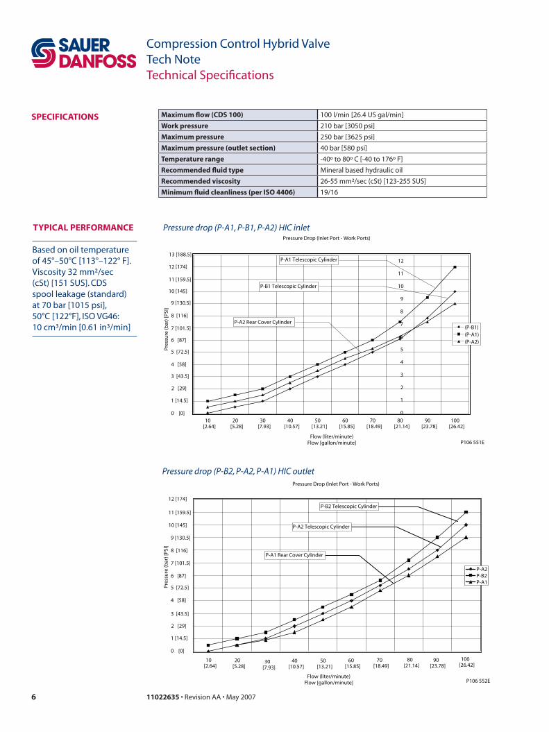
Based on oil temperature of 45°–50°C [113°–122° F]. Viscosity 32 mm²/sec (cSt) [151 SUS]. CDS spool leakage (standard) at 70 bar [1015 psi], 50°C [122°F], ISO VG46: 10 cm³/min [0.61 in³/min]
sPeCifiCations maximum flow (CDs 100) 100 l/min [26.4 US gal/min]
work pressure 210 bar [3050 psi]
maximum pressure 250 bar [3625 psi]
maximum pressure (outlet section) 40 bar [580 psi]
temperature range -40º to 80º C [-40 to 176º F]
Recommended fluid type Mineral based hydraulic oil
Recommended viscosity 26-55 mm²/sec (cSt) [123-255 SUS]
minimum fluid cleanliness (per iso ��06) 19/16
Pressure drop (P-B2, P-A2, P-A1) HIC outlet
Pressure drop (P-A1, P-B1, P-A2) HIC inletPressure Drop (Inlet Port - Work Ports)
10 20 30 40 50 60 70 80 90 100[2.64] [5.28] [7.93] [10.57] [13.21] [15.85] [18.49] [21.14] [23.78] [26.42]
Flow (liter/minute)Flow [gallon/minute]
Pres
sure
(bar
) [PS
I]
(P-B1)(P-A1)(P-A2)
P-A1 Telescopic Cylinder
P-B1 Telescopic Cylinder
P-A2 Rear Cover Cylinder
P106 551E
0
1
2
3
4
5
6
7
8
9
10
11
12
0 [0]
1 [14.5]
2 [29]
3 [43.5]
4 [58]
5 [72.5]
6 [87]
7 [101.5]
8 [116]
9 [130.5]
10 [145]
11 [159.5]
12 [174]
13 [188.5]
Pressure Drop (Inlet Port - Work Ports)
P-A2P-B2P-A1
P-B2 Telescopic Cylinder
P-A2 Telescopic Cylinder
P-A1 Rear Cover Cylinder
P106 552E
Pres
sure
(bar
) [PS
I]
0 [0]
1 [14.5]
2 [29]
3 [43.5]
4 [58]
5 [72.5]
6 [87]
7 [101.5]
8 [116]
9 [130.5]
10 [145]
11 [159.5]
12 [174]
10 20 30 40 50 60 70 80 90 100[2.64] [5.28] [7.93] [10.57] [13.21] [15.85] [18.49] [21.14] [23.78] [26.42]
Flow (liter/minute)Flow [gallon/minute]
7110��635 • Revision AA • May 2007
Compression Control Hybrid ValveTech NoteModel Code
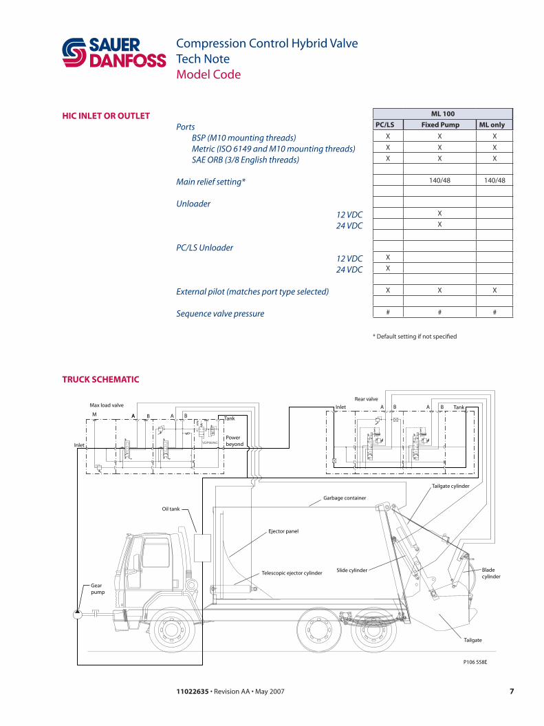
HiC inlet oR outletPorts BSP (M10 mounting threads) Metric (ISO 6149 and M10 mounting threads) SAE ORB (3/8 English threads)
Main relief setting*
Unloader 12 VDC24 VDC
PC/LS Unloader12 VDC24 VDC
External pilot (matches port type selected)
Sequence valve pressure
ml 100
PC/ls fixed Pump ml only
X X X
X X X
X X X
140/48 140/48
X
X
X
X
X X X
# # #
* Default setting if not specified
tRuCk sCHematiC
VDP06/NC
2 31
ATM
M M
Gearpump
P106 558E
Max load valve
M
Inlet
Oil tank
Bladecylinder
Tailgate
Tailgate cylinder
Garbage container
Slide cylinder
Ejector panel
Telescopic ejector cylinder
Powerbeyond
TankAA B A B
Rear valve
Inlet A AB B Tank
� 110��635 • Revision AA • May 2007
Compression Control Hybrid ValveTech NoteModel Code
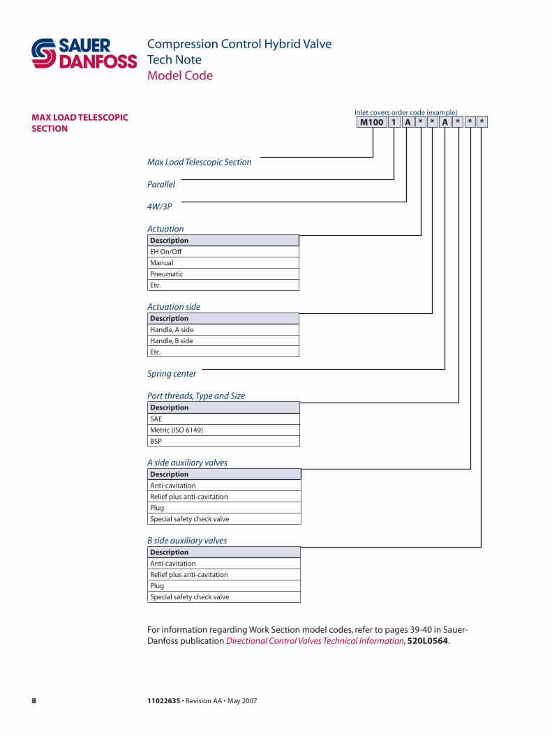
Max Load Telescopic Section
Parallel
4W/3P
ActuationDescription
EH On/Off
Manual
Pneumatic
Etc.
Actuation sideDescription
Handle, A side
Handle, B side
Etc.
max loaD telesCoPiC seCtion
m100 1Inlet covers order code (example)
a * * a * * *
Spring center
Port threads, Type and SizeDescription
SAE
Metric (ISO 6149)
BSP
A side auxiliary valvesDescription
Anti-cavitation
Relief plus anti-cavitation
Plug
Special safety check valve
B side auxiliary valvesDescription
Anti-cavitation
Relief plus anti-cavitation
Plug
Special safety check valve
For information regarding Work Section model codes, refer to pages 39-40 in Sauer-Danfoss publication Directional Control Valves Technical Information, 5�0l056�.
�110��635 • Revision AA • May 2007
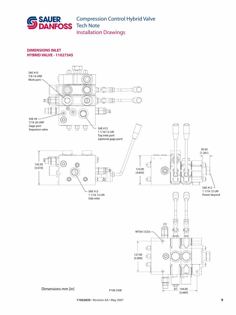
Compression Control Hybrid ValveTech NoteInstallation Drawings
142.50[5.610]
SAE #121 1/16 12-UNSide inlet
123.00[4.843]
SAE #121 1/16 12-UNTop inlet port(optional gage port)
SAE #47/16 20-UNFGage portSequence valve
SAE #107/8 14-UNFWork port
SAE #121 1/16 12-UNPower beyond
30.50[1.201]
144.00[5.669]
M10x1.5(2x)
127.00[5.000]
Dimensions mm [in] P106 550E
Dimensions inlet HybRiD valve - 110�73�5
10 110��635 • Revision AA • May 2007
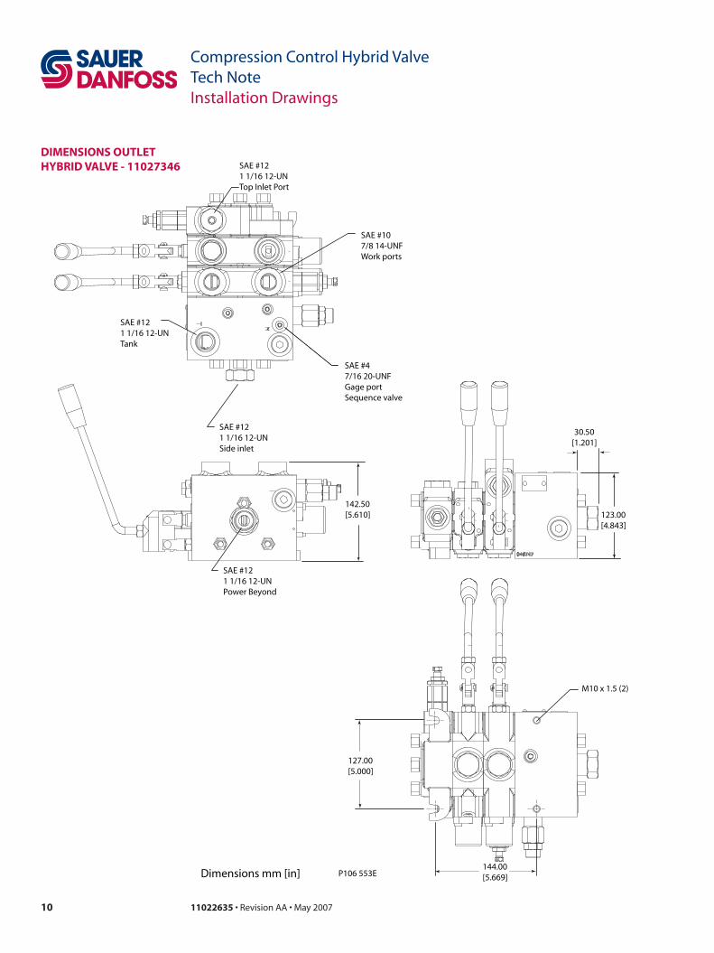
Compression Control Hybrid ValveTech NoteInstallation Drawings
Dimensions outlet HybRiD valve - 110�73�6
142.50[5.610] 123.00
[4.843]
SAE #121 1/16 12-UNTank
SAE #47/16 20-UNFGage portSequence valve
SAE #107/8 14-UNFWork ports
30.50[1.201]
144.00[5.669]
127.00[5.000]
Dimensions mm [in] P106 553E
SAE #121 1/16 12-UNTop Inlet Port
SAE #121 1/16 12-UNPower Beyond
M10 x 1.5 (2)
SAE #121 1/16 12-UNSide inlet
11110��635 • Revision AA • May 2007
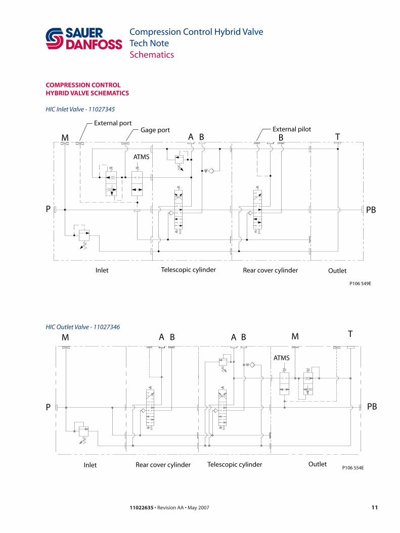
Compression Control Hybrid ValveTech NoteSchematics
HIC Inlet Valve - 11027345
HIC Outlet Valve - 11027346
ComPRession ContRol HybRiD valve sCHematiCs
PBP
Gage portExternal port
M A B BExternal pilot
T
ATMS
Inlet Telescopic cylinder Rear cover cylinder Outlet
P106 549E
P106 554E
PBP
MA B B T
ATMS
Inlet Telescopic cylinderRear cover cylinder Outlet
AM
ouR PRoDuCts
Hydrostatic transmissions
Hydraulic power steering
Electric power steering
Electrohydraulic power steering
Closed and open circuit axial piston pumps and motors
Gear pumps and motors
Bent axis motors
Orbital motors
Transit mixer drives
Planetary compact gears
Proportional valves
Directional spool valves
Cartridge valves
Hydraulic integrated circuits
Hydrostatic transaxles
Integrated systems
Fan drive systems
Electrohydraulics
Microcontrollers and software
Electric motors and inverters
Joysticks and control handles
Displays
Sensors
sauer-Danfoss mobile Power and Control systems– market leaders worldwide
Sauer-Danfoss is a comprehensive supplier providing complete systems to the global mobile market.
Sauer-Danfoss serves markets such as agriculture, construction, road building, material handling, municipal, forestry, turf care, and many others.
We offer our customers optimum solutions for their needs and develop new products and systems in close cooperation and partnership with them.
Sauer-Danfoss specializes in integrating a full range of system components to provide vehicle designers with the most advanced total system design.
Sauer-Danfoss provides comprehensive worldwide service for its products through an extensive network of Global Service Partners strategically located in all parts of the world.
Local address:
Sauer-Danfoss (US) Company2800 East 13th StreetAmes, IA 50010, USAPhone: +1 515 239-6000Fax: +1 515 239-6618
Sauer-Danfoss ApSDK-6430 Nordborg, DenmarkPhone: +45 7488 4444Fax: +45 7488 4400
Sauer-Danfoss-Daikin LTDSannomiya Grand Bldg. 8F2-2-21 Isogami-dori, Chuo-kuKobe, Hyogo 651-0086, JapanPhone: +81 78 231 5001Fax: +81 78 231 5004
Sauer-Danfoss GmbH & Co. OHGPostfach 2460, D-24531 NeumünsterKrokamp 35, D-24539 Neumünster, GermanyPhone: +49 4321 871-0Fax: +49 4321 871 122
www.sauer-danfoss.com110��635 • Revision AA • May 2007