Embed Size (px)
Citation preview
Compressed Natural Gas (CNG) Filters
www.xebecinc.com
FILTRATION for CNG• Dryers• Compressors• Storage Cascades• Dispensers

We understand what service means to you
Products Designed for CNG • Practical solutions developed from 40 years of experience
• Full range of products for one-stop shopping
• Proven quality on a global scale
Exceptional Technical Support• Flexible, fully trained technical team
• Expert advice and simple solutions for the right product, every time
Customers First• Direct line, live support
• Products in stock, ready to ship
• Uncomplicated visual catalogue
XEBEC MISSION
To provide customers with innovative solutions which transform raw natural gas into marketable sources of clean energy.
Expert Problem Solvers on a Global Scale
Founded in 1967, Xebec has over 40 years of experience in adsorption technology, the foundation of all of Xebec’s systems. To date, Xebec has supplied more than 9000 adsorption systems, built to ASME, National Code or PED specifications, to more than 1500 customers worldwide. With major installations throughout North America, China, Russia, Australia, South America, Indonesia and the Middle East, Xebec offers worldwide service and support through a dedicated CNG team, providing design services, installation expertise and systems development for end-to-end solutions.
2 3
The ApplicationWhat is Compressed Natural Gas (CNG)?
CNG is natural gas that is highly compressed and stored in thick-walled steel, aluminum, or composite high-pressure storage containers. CNG is a clear and non-corrosive alternative transportation fuel for automobiles, trucks and buses. Its use is becoming more and more popular because it is less expensive than gasoline and it is far more friendly to the environment with reductions of CO2, nitrous-oxide, and particulate emissions. As a result, many governments financially encourage the conversion and use of this alternative fuel as an energy source.
The Problem
In NGV Fueling Stations, natural gas is taken from a pipeline and compressed to pressures ranging from 2000 psig up to 6000 psig. The resulting CNG is then stored in large tanks before making its way to a gas dispenser where it is ready for use in vehicles.
CNG, like all fuels, experiences contamination as it travels from pipeline to dispenser. Like traditional fuels, solids collect during handling, water condenses in tanks, and compressor lube oils carry over into the CNG stream. Contaminants are also present within the delivery system that can lead to compressor fouling, vehicle fuel system repair, liquids in storage tanks, and gas dispenser replacement.
The Solution
Filters are essential for compressed natural gas treatment and are present throughout the treatment chain. CNG filters remove all types of solid and liquid contaminants in stages — large amounts of condensate and coarse contamination particles such as rust, abrasion particles, oil droplets, and dust in the first stages; fine oil mist and fine dust particles in subsequent stages. Compressed gas filters containing activated carbon also remove oil and oil vapour.
CNG Filters – Design and Accessories
• Filter Elements: The core of a compressed gas filter separates levels of contaminants from the compressed gas, depending on the filter media and grade. The element permanently captures the solid particles. It then requires periodic replacement dependent on the level of contamination.
• Filter Housings: Pressure housings with a method for supporting the filter element, a compressed gas inlet and outlet with the flow paths to and from the filter element, a condensate outlet for discharging separated liquids, and connections for monitoring the differential pressure across the filter element.
• Differential Pressure Gauges: Measure the differential pressure across the filter element. They indicate when a filter element needs to be replaced, either because it has reached the end of its useful life, or large amount of contamination has been discharged upstream.
• Manual Condensate Drains: Used for manually discharging the separated liquids and for pressure relief of the filter.
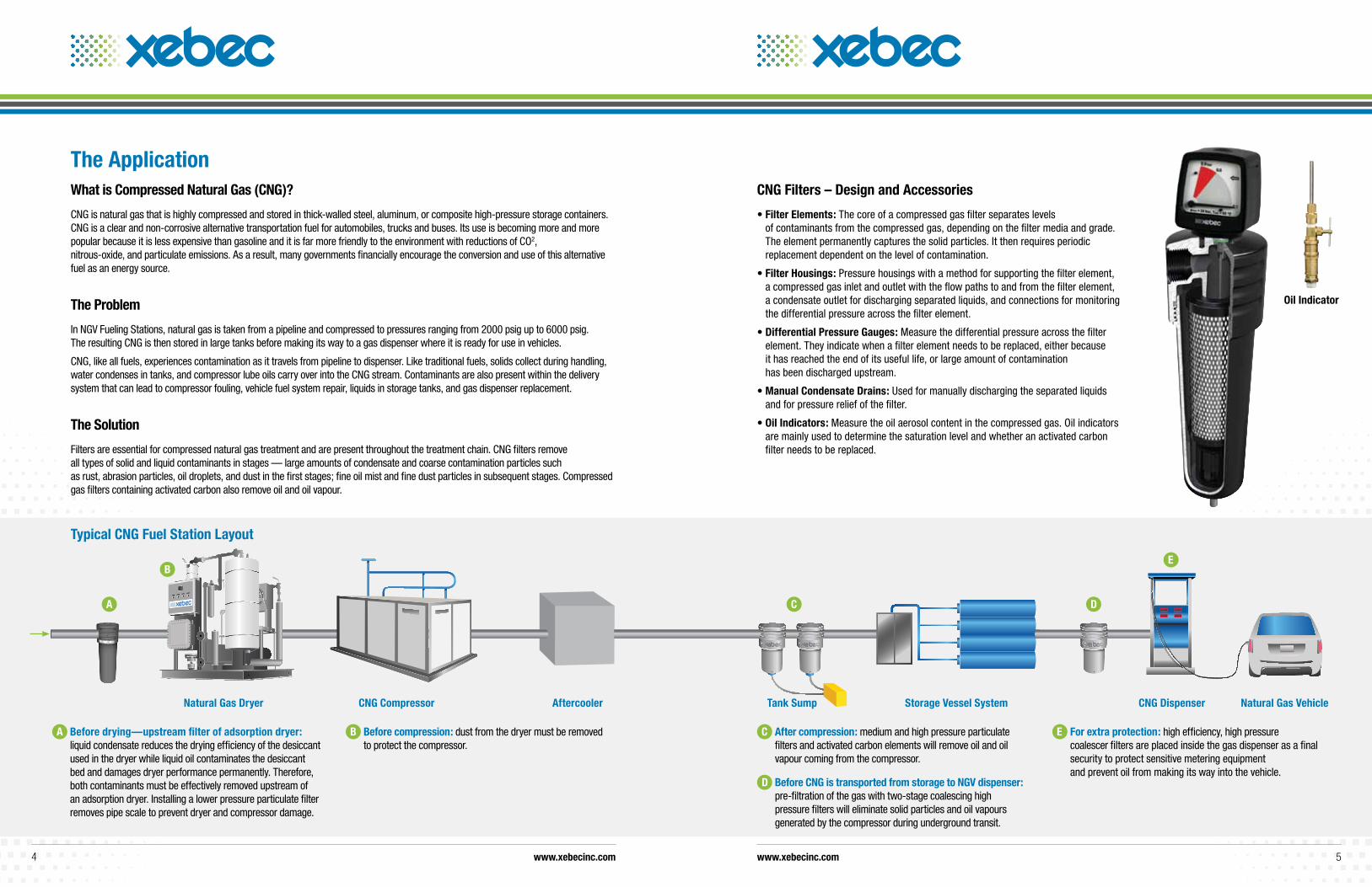
• Oil Indicators: Measure the oil aerosol content in the compressed gas. Oil indicators are mainly used to determine the saturation level and whether an activated carbon filter needs to be replaced.
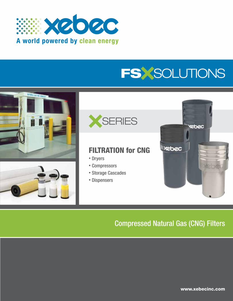
Typical CNG Fuel Station Layout
A Before drying—upstream filter of adsorption dryer: liquid condensate reduces the drying efficiency of the desiccant used in the dryer while liquid oil contaminates the desiccant bed and damages dryer performance permanently. Therefore, both contaminants must be effectively removed upstream of an adsorption dryer. Installing a lower pressure particulate filter removes pipe scale to prevent dryer and compressor damage.
C After compression: medium and high pressure particulate filters and activated carbon elements will remove oil and oil vapour coming from the compressor.
D Before CNG is transported from storage to NGV dispenser: pre-filtration of the gas with two-stage coalescing high pressure filters will eliminate solid particles and oil vapours generated by the compressor during underground transit.
B Before compression: dust from the dryer must be removed to protect the compressor.
E For extra protection: high efficiency, high pressure coalescer filters are placed inside the gas dispenser as a final security to protect sensitive metering equipment and prevent oil from making its way into the vehicle.
Oil Indicator
Natural Gas Dryer CNG Compressor Aftercooler Tank Sump Storage Vessel System CNG Dispenser Natural Gas Vehicle
A
B
C D
E
www.xebecinc.com www.xebecinc.com4 5
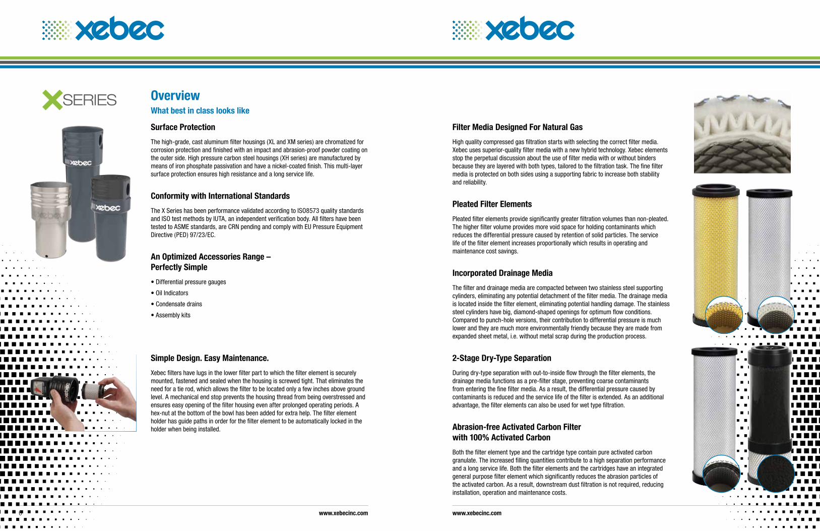
Filter Media Designed For Natural Gas
High quality compressed gas filtration starts with selecting the correct filter media. Xebec uses superior-quality filter media with a new hybrid technology. Xebec elements stop the perpetual discussion about the use of filter media with or without binders because they are layered with both types, tailored to the filtration task. The fine filter media is protected on both sides using a supporting fabric to increase both stability and reliability.
Pleated Filter Elements
Pleated filter elements provide significantly greater filtration volumes than non-pleated. The higher filter volume provides more void space for holding contaminants which reduces the differential pressure caused by retention of solid particles. The service life of the filter element increases proportionally which results in operating and maintenance cost savings.
Incorporated Drainage Media
The filter and drainage media are compacted between two stainless steel supporting cylinders, eliminating any potential detachment of the filter media. The drainage media is located inside the filter element, eliminating potential handling damage. The stainless steel cylinders have big, diamond-shaped openings for optimum flow conditions. Compared to punch-hole versions, their contribution to differential pressure is much lower and they are much more environmentally friendly because they are made from expanded sheet metal, i.e. without metal scrap during the production process.
2-Stage Dry-Type Separation
During dry-type separation with out-to-inside flow through the filter elements, the drainage media functions as a pre-filter stage, preventing coarse contaminants from entering the fine filter media. As a result, the differential pressure caused by contaminants is reduced and the service life of the filter is extended. As an additional advantage, the filter elements can also be used for wet type filtration.
Abrasion-free Activated Carbon Filter with 100% Activated Carbon
Both the filter element type and the cartridge type contain pure activated carbon granulate. The increased filling quantities contribute to a high separation performance and a long service life. Both the filter elements and the cartridges have an integrated general purpose filter element which significantly reduces the abrasion particles of the activated carbon. As a result, downstream dust filtration is not required, reducing installation, operation and maintenance costs.
OverviewWhat best in class looks like
Surface Protection
The high-grade, cast aluminum filter housings (XL and XM series) are chromatized for corrosion protection and finished with an impact and abrasion-proof powder coating on the outer side. High pressure carbon steel housings (XH series) are manufactured by means of iron phosphate passivation and have a nickel-coated finish. This multi-layer surface protection ensures high resistance and a long service life.
Conformity with International Standards
The X Series has been performance validated according to ISO8573 quality standards and ISO test methods by IUTA, an independent verification body. All filters have been tested to ASME standards, are CRN pending and comply with EU Pressure Equipment Directive (PED) 97/23/EC.
An Optimized Accessories Range – Perfectly Simple
• Differential pressure gauges
• Oil Indicators
• Condensate drains
• Assembly kits
Simple Design. Easy Maintenance.
Xebec filters have lugs in the lower filter part to which the filter element is securely mounted, fastened and sealed when the housing is screwed tight. That eliminates the need for a tie rod, which allows the filter to be located only a few inches above ground level. A mechanical end stop prevents the housing thread from being overstressed and ensures easy opening of the filter housing even after prolonged operating periods. A hex-nut at the bottom of the bowl has been added for extra help. The filter element holder has guide paths in order for the filter element to be automatically locked in the holder when being installed.
www.xebecinc.com www.xebecinc.com6 7
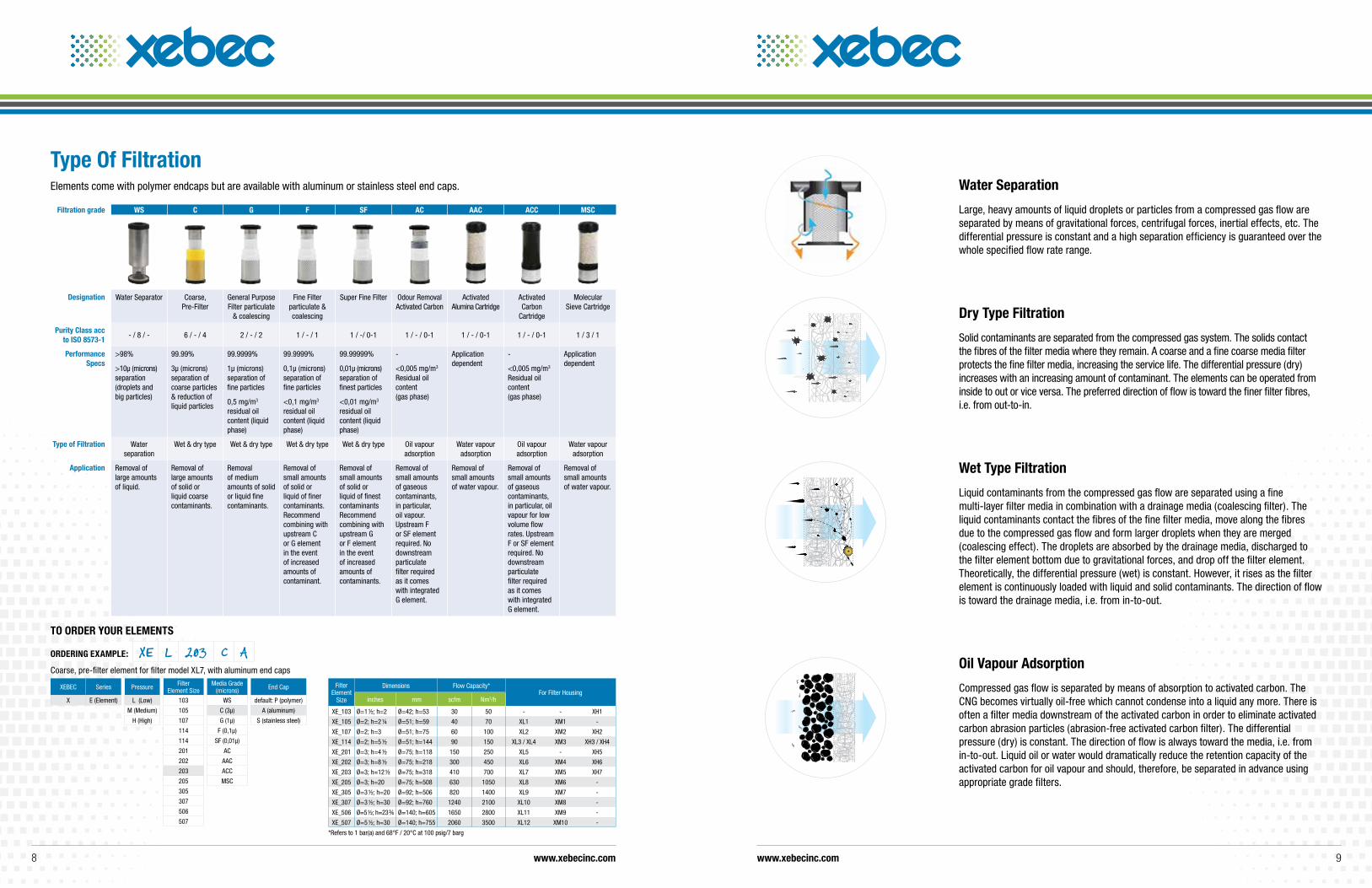
Water Separation
Large, heavy amounts of liquid droplets or particles from a compressed gas flow are separated by means of gravitational forces, centrifugal forces, inertial effects, etc. The differential pressure is constant and a high separation efficiency is guaranteed over the whole specified flow rate range.
Filtration grade WS C G F SF AC AAC ACC MSC
Designation Water Separator Coarse, Pre-Filter
General Purpose Filter particulate
& coalescing
Fine Filter particulate & coalescing
Super Fine Filter Odour Removal Activated Carbon
Activated Alumina Cartridge
Activated Carbon
Cartridge
Molecular Sieve Cartridge
Purity Class acc to ISO 8573-1
- / 8 / - 6 / - / 4 2 / - / 2 1 / - / 1 1 / -/ 0-1 1 / - / 0-1 1 / - / 0-1 1 / - / 0-1 1 / 3 / 1
Performance Specs
>98%
>10µ (microns) separation (droplets and big particles)
99.99%
3µ (microns) separation of coarse particles & reduction of liquid particles
99.9999%
1µ (microns) separation of fine particles
0,5 mg/m3 residual oil content (liquid phase)
99.9999%
0,1µ (microns)separation of fine particles
<0,1 mg/m3 residual oil content (liquid phase)
99.99999%
0,01µ (microns)separation of finest particles
<0,01 mg/m3 residual oil content (liquid phase)
-
<0,005 mg/m3 Residual oil content (gas phase)
Application dependent
-
<0,005 mg/m3 Residual oil content (gas phase)
Application dependent
Type of Filtration Water separation
Wet & dry type Wet & dry type Wet & dry type Wet & dry type Oil vapour adsorption
Water vapour adsorption
Oil vapour adsorption
Water vapour adsorption
Application Removal of large amounts of liquid.
Removal of large amounts of solid or liquid coarse contaminants.
Removal of medium amounts of solid or liquid fine contaminants.
Removal of small amounts of solid or liquid of finer contaminants. Recommend combining with upstream C or G element in the event of increased amounts of contaminant.
Removal of small amounts of solid or liquid of finest contaminants Recommend combining with upstream G or F element in the event of increased amounts of contaminants.
Removal of small amounts of gaseous contaminants, in particular, oil vapour. Upstream F or SF element required. No downstream particulate filter required as it comes with integrated G element.
Removal of small amounts of water vapour.
Removal of small amounts of gaseous contaminants, in particular, oil vapour for low volume flow rates. Upstream F or SF element required. No downstream particulate filter required as it comes with integrated G element.
Removal of small amounts of water vapour.
Type Of FiltrationElements come with polymer endcaps but are available with aluminum or stainless steel end caps.
XEBEC Series Pressure Filter Element Size
Media Grade (microns) End Cap
X E (Element) L (Low) 103 WS default: P (polymer)
M (Medium) 105 C (3µ) A (aluminum)
H (High) 107 G (1µ) S (stainless steel)
114 F (0,1µ)
114 SF (0,01µ)
201 AC
202 AAC
203 ACC
205 MSC
305
307
506
507
TO ORDER yOuR ELEMENTS
ORDERING EXAMPLE: XE L 203 C ACoarse, pre-filter element for filter model XL7, with aluminum end caps
Filter Element
Size
Dimensions Flow Capacity*For Filter Housing
inches mm scfm Nm3/h
XE_103 Ø=1 ½; h=2 Ø=42; h=53 30 50 - - XH1
XE_105 Ø=2; h=2 ¼ Ø=51; h=59 40 70 XL1 XM1 -
XE_107 Ø=2; h=3 Ø=51; h=75 60 100 XL2 XM2 XH2
XE_114 Ø=2; h=5 ½ Ø=51; h=144 90 150 XL3 / XL4 XM3 XH3 / XH4
XE_201 Ø=3; h=4 ½ Ø=75; h=118 150 250 XL5 - XH5
XE_202 Ø=3; h=8 ½ Ø=75; h=218 300 450 XL6 XM4 XH6
XE_203 Ø=3; h=12 ½ Ø=75; h=318 410 700 XL7 XM5 XH7
XE_205 Ø=3; h=20 Ø=75; h=508 630 1050 XL8 XM6 -
XE_305 Ø=3 ½; h=20 Ø=92; h=506 820 1400 XL9 XM7 -
XE_307 Ø=3 ½; h=30 Ø=92; h=760 1240 2100 XL10 XM8 -
XE_506 Ø=5 ½; h=23 ¾ Ø=140; h=605 1650 2800 XL11 XM9 -
XE_507 Ø=5 ½; h=30 Ø=140; h=755 2060 3500 XL12 XM10 -
*Refers to 1 bar(a) and 68°F / 20°C at 100 psig/7 barg
Dry Type Filtration
Solid contaminants are separated from the compressed gas system. The solids contact the fibres of the filter media where they remain. A coarse and a fine coarse media filter protects the fine filter media, increasing the service life. The differential pressure (dry) increases with an increasing amount of contaminant. The elements can be operated from inside to out or vice versa. The preferred direction of flow is toward the finer filter fibres, i.e. from out-to-in.
Wet Type Filtration
Liquid contaminants from the compressed gas flow are separated using a fine multi-layer filter media in combination with a drainage media (coalescing filter). The liquid contaminants contact the fibres of the fine filter media, move along the fibres due to the compressed gas flow and form larger droplets when they are merged (coalescing effect). The droplets are absorbed by the drainage media, discharged to the filter element bottom due to gravitational forces, and drop off the filter element. Theoretically, the differential pressure (wet) is constant. However, it rises as the filter element is continuously loaded with liquid and solid contaminants. The direction of flow is toward the drainage media, i.e. from in-to-out.
Oil Vapour Adsorption
Compressed gas flow is separated by means of absorption to activated carbon. The CNG becomes virtually oil-free which cannot condense into a liquid any more. There is often a filter media downstream of the activated carbon in order to eliminate activated carbon abrasion particles (abrasion-free activated carbon filter). The differential pressure (dry) is constant. The direction of flow is always toward the media, i.e. from in-to-out. Liquid oil or water would dramatically reduce the retention capacity of the activated carbon for oil vapour and should, therefore, be separated in advance using appropriate grade filters.
www.xebecinc.com www.xebecinc.com8 9
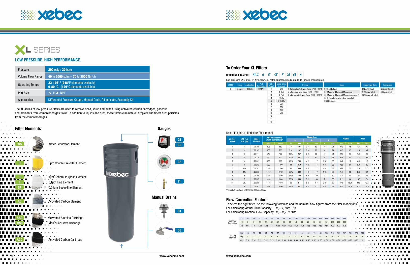
Pressure 290 psig / 20 barg
Volume Flow Range 40 to 2060 scfm – 70 to 3500 Nm3/h
Operating Temps 32-176°F (248°F elements available) 0-80 °C (120°C elements available)
Port Size ¼" to 3" NPT
Accessories Differential Pressure Gauge, Manual Drain, Oil Indicator, Assembly Kit
The XL series of low pressure filters are used to remove solid, liquid and, when using activated carbon cartridges, gaseous contaminants from compressed gas flows. In addition to liquids and dust, these filters eliminate oil droplets and finest dust particles from the compressed gas.
Filter Elements
3µm Coarse Pre-filter Element
1µm General Purpose ElementG
0,1µm Fine ElementF
0,01µm Super-fine ElementSF
Activated Carbon ElementAC
Activated Alumina Cartridge
Molecular Sieve Cartridge
Activated Carbon Cartridge
AAC
MSC
ACC
LOW PRESSuRE. HIGH PERFORMANCE.
Water Separator ElementWS
C
Operating Temperature
°F 32 41 50 59 68 77 86 95 104 122 140 158 176 194 221 230 248
°C 0 5 10 15 20 25 30 35 40 50 60 70 80 90 100 110 120
Cft 1.07 1.1 1.04 1.02 1 0.98 0.97 0.95 0.94 0.91 0.88 0.85 0.83 0.81 0.79 0.77 0.75
Operating Pressure
psig 15 29 44 58 73 87 100 116 131 145 160 174 189 203 218 232 247 261 276 290
barg 1 2 3 4 5 6 7 8 9 10 11 12 13 14 15 16 17 18 19 20
Cfp 0.10 0.14 0.19 0.24 0.29 0.34 0.38 0.43 0.48 0.52 0.57 0.62 0.67 0.71 0.76 0.81 0.85 0.90 0.96 1
Flow Correction Factors To select the right filter use the following formulas and the nominal flow figures from the filter model table: For calculating Actual Flow Capacity: Va= Vn *Cft *Cfp For calculating Nominal Flow Capacity: Vn = Va / Cft / Cfp
XEBEC Series Application Port Connection
Filter Model
Media Grade (microns) End Cap Gauge Condensate Drain Accessories
X L (Low) C (CNG) N (NPT) 1 WS P (Polymer) default Max. Temp. 176°F / 80°C N (None) Default N (None) Default N (None) Default
2 C (3µ) A (aluminum) Max. Temp. 248°F / 120°C G1 (Magnetic Differential Manometer) D1 (Manual valve) AK (assembly kit)
3 G (1µ) S (stainless steel) Max. Temp. 248°F / 120°C G2 (Magnetic Differential Manometer w/alarm) D3 (Manual ball valve)
4 F (0,1µ) G3 (Differential pressure drop indicator)
5 SF (0,01µ) I1 (Oil Indicator)
6 AC
7 AAC
8 ACC
9 MSC
10
11
12
To Order your XL Filters
ORDERING EXAMPLE: XLC N 5 SF P G1 D1 NLow pressure CNG filter, ¾" NPT, flow 400 scfm, superfine media grade, DP gauge, manual drain.
Use this table to find your filter model.
XL Filter Model
NPT Port Size (in)
Filter Element
CNG flow capacity at 290 psig/20 barg*
DimensionsVolume Mass
A B C
scfm Nm3/h in mm in mm in mm gals liters lbs kgs
1 ¼ XEL105 105 180 7 ¾ 197 3 ¼ 80 ¾ 21 0.13 0,5 1.5 0,7
2 3⁄8 XEL107 160 260 7 ¾ 197 3 ¼ 80 ¾ 21 0.13 0,5 1.5 0,7
3 ½ XEL114 240 400 10 ½ 267 3 ¼ 80 ¾ 21 0.18 0,7 1.8 0,8
4 ¾ XEL114 240 400 10 ½ 267 3 ¼ 80 ¾ 21 0.18 0,7 1.8 0,8
5 ¾ XEL201 400 660 10 ¼ 259 4 ½ 117 1 ¼ 33 0.42 1,6 4.0 1,8
6 1 XEL202 780 1200 14 359 4 ½ 117 1 ¼ 33 0.55 2,1 5.0 2,2
7 1 ½ XEL203 1080 1850 18 459 4 ½ 117 1 ¼ 33 0.71 2,7 5.5 2,5
8 1 ½ XEL205 1660 2760 25 ¼ 639 4 ½ 117 1 ¼ 33 1.0 3,8 6.8 3,1
9 2 XEL305 2160 3700 27 ½ 700 5 ½ 140 2 50 1.6 6,1 12.1 5,5
10 2 XEL307 3260 5500 37 ¼ 950 5 ½ 140 2 50 2.2 8,4 16.3 7,4
11 2 ½ XEL506 4340 7370 32 811 8 ½ 217 2 ¾ 69 4.46 16,9 30.0 13,6
12 3 XEL507 5400 9200 39 ½ 1003 8 ½ 217 2 ¾ 69 5.52 20,9 37.3 16,9
*Refers to 1 bar(a) and 68°F/20°C at 290 psig/20barg
A
B
C
Gauges
Manual Drains
G1
G2
D1
D3
I1
G3
www.xebecinc.com www.xebecinc.com10 11
D3
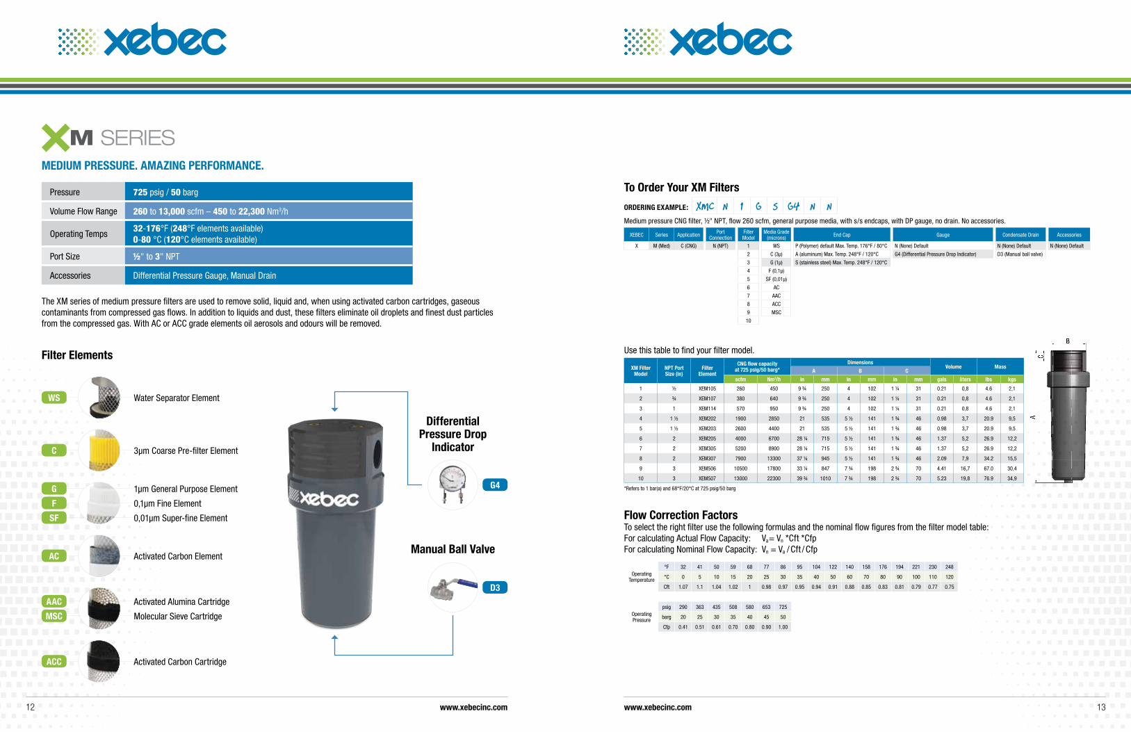
Pressure 725 psig / 50 barg
Volume Flow Range 260 to 13,000 scfm – 450 to 22,300 Nm3/h
Operating Temps 32-176°F (248°F elements available) 0-80 °C (120°C elements available)
Port Size ½" to 3" NPT
Accessories Differential Pressure Gauge, Manual Drain
The XM series of medium pressure filters are used to remove solid, liquid and, when using activated carbon cartridges, gaseous contaminants from compressed gas flows. In addition to liquids and dust, these filters eliminate oil droplets and finest dust particles from the compressed gas. With AC or ACC grade elements oil aerosols and odours will be removed.
MEDIuM PRESSuRE. AMAzING PERFORMANCE.
Filter Elements
3µm Coarse Pre-filter Element
1µm General Purpose Element
0,1µm Fine Element
0,01µm Super-fine Element
Activated Carbon Element
Activated Alumina Cartridge
Molecular Sieve Cartridge
Activated Carbon Cartridge
Water Separator Element
Differential Pressure Drop
Indicator
Manual Ball Valve
G4
Use this table to find your filter model.
XM Filter Model
NPT Port Size (in)
Filter Element
CNG flow capacity at 725 psig/50 barg*
DimensionsVolume Mass
A B C
scfm Nm3/h in mm in mm in mm gals liters lbs kgs
1 ½ XEM105 260 450 9 ¾ 250 4 102 1 ¼ 31 0.21 0,8 4.6 2,1
2 ¾ XEM107 380 640 9 ¾ 250 4 102 1 ¼ 31 0.21 0,8 4.6 2,1
3 1 XEM114 570 950 9 ¾ 250 4 102 1 ¼ 31 0.21 0,8 4.6 2,1
4 1 ½ XEM202 1900 2850 21 535 5 ½ 141 1 ¾ 46 0.98 3,7 20.9 9,5
5 1 ½ XEM203 2600 4400 21 535 5 ½ 141 1 ¾ 46 0.98 3,7 20.9 9,5
6 2 XEM205 4000 6700 28 ¼ 715 5 ½ 141 1 ¾ 46 1.37 5,2 26.9 12,2
7 2 XEM305 5200 8900 28 ¼ 715 5 ½ 141 1 ¾ 46 1.37 5,2 26.9 12,2
8 2 XEM307 7900 13300 37 ¼ 945 5 ½ 141 1 ¾ 46 2.09 7,9 34.2 15,5
9 3 XEM506 10500 17800 33 ¼ 847 7 ¾ 198 2 ¾ 70 4.41 16,7 67.0 30,4
10 3 XEM507 13000 22300 39 ¾ 1010 7 ¾ 198 2 ¾ 70 5.23 19,8 76.9 34,9
*Refers to 1 bar(a) and 68°F/20°C at 725 psig/50 bargG
F
SF
AC
AAC
MSC
ACC
WS
C
XEBEC Series Application Port Connection
Filter Model
Media Grade (microns) End Cap Gauge Condensate Drain Accessories
X M (Med) C (CNG) N (NPT) 1 WS P (Polymer) default Max. Temp. 176°F / 80°C N (None) Default N (None) Default N (None) Default
2 C (3µ) A (aluminum) Max. Temp. 248°F / 120°C G4 (Differential Pressure Drop Indicator) D3 (Manual ball valve)
3 G (1µ) S (stainless steel) Max. Temp. 248°F / 120°C
4 F (0,1µ)
5 SF (0,01µ)
6 AC
7 AAC
8 ACC
9 MSC
10
To Order your XM Filters
ORDERING EXAMPLE: XMC N 1 G S G4 N NMedium pressure CNG filter, ½" NPT, flow 260 scfm, general purpose media, with s/s endcaps, with DP gauge, no drain. No accessories.
A
B
C
Operating Pressure
psig 290 363 435 508 580 653 725
barg 20 25 30 35 40 45 50
Cfp 0.41 0.51 0.61 0.70 0.80 0.90 1.00
Operating Temperature
°F 32 41 50 59 68 77 86 95 104 122 140 158 176 194 221 230 248
°C 0 5 10 15 20 25 30 35 40 50 60 70 80 90 100 110 120
Cft 1.07 1.1 1.04 1.02 1 0.98 0.97 0.95 0.94 0.91 0.88 0.85 0.83 0.81 0.79 0.77 0.75
Flow Correction Factors To select the right filter use the following formulas and the nominal flow figures from the filter model table: For calculating Actual Flow Capacity: Va= Vn *Cft *Cfp For calculating Nominal Flow Capacity: Vn = Va / Cft / Cfp
www.xebecinc.com www.xebecinc.com12 13
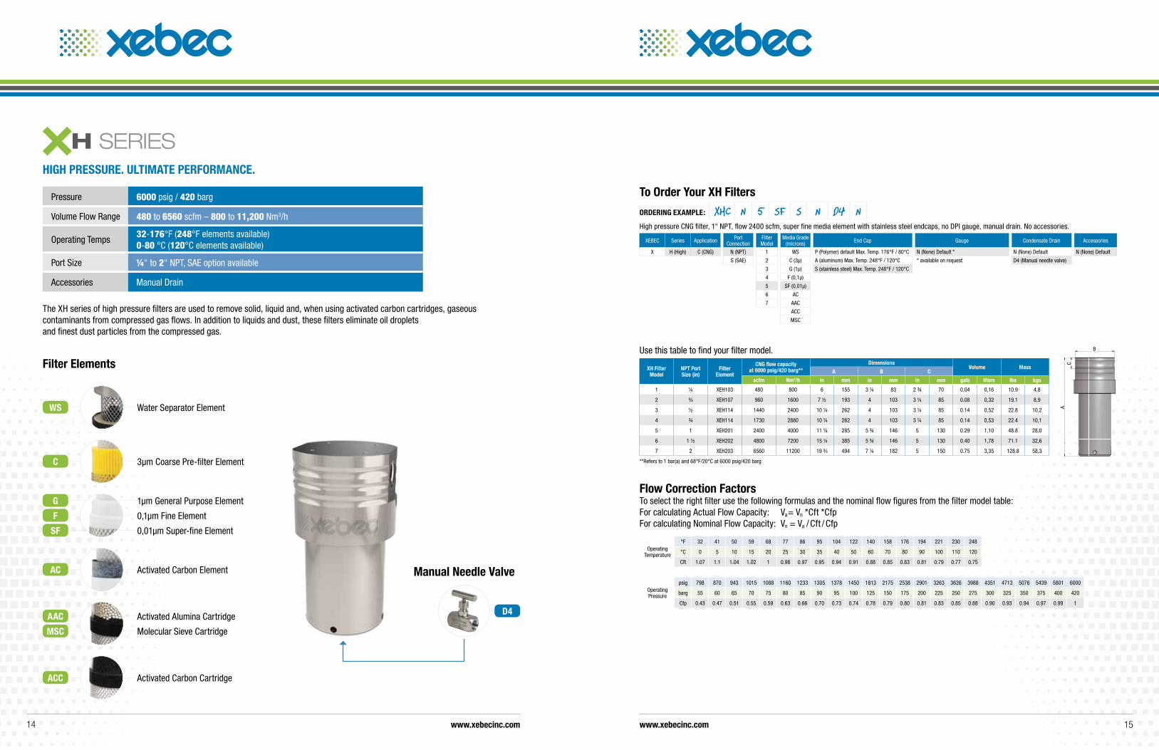
Pressure 6000 psig / 420 barg
Volume Flow Range 480 to 6560 scfm – 800 to 11,200 Nm3/h
Operating Temps 32-176°F (248°F elements available) 0-80 °C (120°C elements available)
Port Size ¼" to 2" NPT, SAE option available
Accessories Manual Drain
The XH series of high pressure filters are used to remove solid, liquid and, when using activated carbon cartridges, gaseous contaminants from compressed gas flows. In addition to liquids and dust, these filters eliminate oil droplets and finest dust particles from the compressed gas.
Filter Elements
D4
Manual Needle Valve
XEBEC Series Application Port Connection
Filter Model
Media Grade (microns) End Cap Gauge Condensate Drain Accessories
X H (High) C (CNG) N (NPT) 1 WS P (Polymer) default Max. Temp. 176°F / 80°C N (None) Default * N (None) Default N (None) Default
S (SAE) 2 C (3µ) A (aluminum) Max. Temp. 248°F / 120°C * available on request D4 (Manual needle valve)
3 G (1µ) S (stainless steel) Max. Temp. 248°F / 120°C
4 F (0,1µ)
5 SF (0,01µ)
6 AC
7 AAC
ACC
MSC
To Order your XH Filters
ORDERING EXAMPLE: XHC N 5 SF S N D4 NHigh pressure CNG filter, 1" NPT, flow 2400 scfm, super fine media element with stainless steel endcaps, no DPI gauge, manual drain. No accessories.
Use this table to find your filter model.
XH Filter Model
NPT Port Size (in)
Filter Element
CNG flow capacity at 6000 psig/420 barg**
DimensionsVolume Mass
A B C
scfm Nm3/h in mm in mm in mm gals liters lbs kgs
1 ¼ XEH103 480 800 6 155 3 ¼ 83 2 ¾ 70 0.04 0,16 10.9 4,8
2 ³⁄8 XEH107 960 1600 7 ½ 193 4 103 3 ¼ 85 0.08 0,32 19.1 8,9
3 ½ XEH114 1440 2400 10 ¼ 262 4 103 3 ¼ 85 0.14 0,52 22.8 10,2
4 ¾ XEH114 1730 2880 10 ¼ 262 4 103 3 ¼ 85 0.14 0,53 22.4 10,1
5 1 XEH201 2400 4000 11 ¼ 285 5 ¾ 146 5 130 0.29 1,10 48.8 28,0
6 1 ½ XEH202 4800 7200 15 ¼ 385 5 ¾ 146 5 130 0.40 1,78 71.1 32,6
7 2 XEH203 6560 11200 19 ³⁄8 494 7 ¼ 182 5 150 0.75 3,35 128.8 58,3
**Refers to 1 bar(a) and 68°F/20°C at 6000 psig/420 barg
A
B
C
HIGH PRESSuRE. uLTIMATE PERFORMANCE.
Operating Pressure
psig 798 870 943 1015 1088 1160 1233 1305 1378 1450 1813 2175 2538 2901 3263 3626 3988 4351 4713 5076 5439 5801 6000
barg 55 60 65 70 75 80 85 90 95 100 125 150 175 200 225 250 275 300 325 350 375 400 420
Cfp 0.43 0.47 0.51 0.55 0.59 0.63 0.66 0.70 0.73 0.74 0.78 0.79 0.80 0.81 0.83 0.85 0.88 0.90 0.93 0.94 0.97 0.99 1
Operating Temperature
°F 32 41 50 59 68 77 86 95 104 122 140 158 176 194 221 230 248
°C 0 5 10 15 20 25 30 35 40 50 60 70 80 90 100 110 120
Cft 1.07 1.1 1.04 1.02 1 0.98 0.97 0.95 0.94 0.91 0.88 0.85 0.83 0.81 0.79 0.77 0.75
Flow Correction Factors To select the right filter use the following formulas and the nominal flow figures from the filter model table: For calculating Actual Flow Capacity: Va= Vn *Cft *Cfp For calculating Nominal Flow Capacity: Vn = Va / Cft / Cfp
www.xebecinc.com www.xebecinc.com14 15
3µm Coarse Pre-filter Element
1µm General Purpose Element
0,1µm Fine Element
0,01µm Super-fine Element
Activated Carbon Element
Activated Alumina Cartridge
Molecular Sieve Cartridge
Activated Carbon Cartridge
Water Separator Element
G
F
SF
AC
AAC
MSC
ACC
WS
C
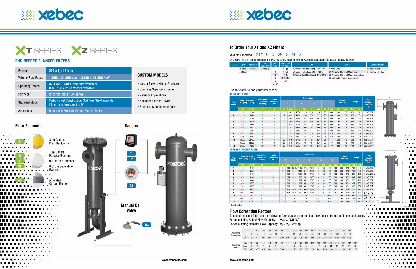
CuSTOM MODELS
• Larger Flows / Higher Pressures
• Stainless Steel Construction
• Vacuum Applications
• Activated Carbon Tower
• Stainless Steel Internal Parts
Use this table to find your filter model.XT INLINE FILTER
Filter Model
Flow Capacity @ 100 psig / 7 bar g
Inlet/Outlet Connection
150# Flg
Drain Connection
NPT
DimensionsDesign
Pressure WeightFilter
Element Quantity/
TypeA B C D
scfm Nm³/hr in in in mm in mm in mm in mm psig bar g lbs kg
1 1250 2100 2 ½ 15 381 47 7⁄8 1216 8 ½ 216 26 660 260 17.9 120 54 1 x XEL307
2 2100 3550 3 ½ 17 432 49 1⁄8 1248 8 ¾ 222 26 660 260 17.9 176 80 1 x XEL507
3 2450 4150 4 ½ 20 508 52 5⁄8 1337 9 7⁄8 251 26 660 260 17.9 238 108 2 x XEL307
4 3700 6280 4 ½ 20 508 52 5⁄8 1337 9 7⁄8 251 26 660 260 17.9 242 110 3 x XEL307
5 5100 8660 6 ½ 25 635 57 3⁄8 1457 11 ¾ 298 26 660 260 17.9 330 150 4 x XEL307
6 6280 10650 6 1 31 787 59 ¼ 1505 14 356 26 660 260 17.9 452 205 5 x XEL307
7 7450 12650 6 1 31 787 59 ¼ 1505 14 356 26 660 260 17.9 456 207 6 x XEL307
8 9800 16650 8 1 31 787 62 ¼ 1581 14 ½ 368 24 610 260 17.9 511 232 8 x XEL307
9 12350 20980 8 1 33 838 62 3⁄8 1584 14 ½ 368 24 610 260 17.9 794 360 10 x XEL307
10 15000 25400 10 1 37 940 67 ¾ 1721 18 457 28 711 260 17.9 992 450 12 x XEL307
11 19300 32800 10 1 37 940 67 ¾ 1721 18 457 28 711 260 17.9 1036 470 16 x XEL307
12 24300 41280 12 1 37 940 65 7⁄8 1673 18 457 28 711 260 17.9 1168 530 20 x XEL307
A
B
C
D
D
B
AE
C
Xz FREE STANDING FILTER
Filter Model
Flow Capacity @ 100 psig / 7 bar g
Inlet/Outlet Connection
150# Flg
Drain Connection
NPT
DimensionsDesign
Pressure WeightFilter
Element Quantity/
TypeA B C D E
scfm Nm³/hr in in in mm in mm in mm in mm in mm psig bar g lbs kg
1 1250 2100 2 ½ 8 203 57 3⁄8 1457 50 3⁄8 1280 6 152 30 762 260 17.9 120 54 1 x XEL307
2 2100 3550 3 ½ 9 229 61 ½ 1562 54 ½ 1384 6 152 30 762 260 17.9 176 80 1 x XEL507
3 2450 4150 4 ½ 10 254 67 ¼ 1708 56 5⁄8 1438 6 152 30 762 260 17.9 238 108 2 x XEL307
4 3700 6280 4 ½ 10 254 67 ¼ 1708 56 5⁄8 1438 6 152 30 762 260 17.9 242 110 3 x XEL307
5 5100 8660 6 ½ 13 330 73 ½ 1867 60 7⁄8 1546 8 203 30 762 260 17.9 330 150 4 x XEL307
6 6280 10650 6 1 13 330 73 ½ 1867 60 7⁄8 1546 8 203 30 762 260 17.9 452 205 5 x XEL307
7 7450 12650 6 1 13 330 73 ½ 1867 60 7⁄8 1546 8 203 30 762 260 17.9 456 207 6 x XEL307
8 9800 16650 8 1 16 406 80 ½ 2045 66 ½ 1689 8 203 30 762 260 17.9 511 232 8 x XEL307
9 12350 20980 8 1 16 406 80 ½ 2045 66 ½ 1689 8 203 30 762 260 17.9 794 360 10 x XEL307
10 15000 25400 10 1 C/F* C/F* C/F* C/F* C/F* 260 17.9 992 450 12 x XEL307
11 19300 32800 10 1 C/F* C/F* C/F* C/F* C/F* 260 17.9 1036 470 16 x XEL307
12 24300 41280 12 1 C/F* C/F* C/F* C/F* C/F* 260 17.9 1168 530 20 x XEL307
* Consult factory
ENGINEERED FLANGED FILTERS
Pressure 260 psig / 18 barg
Volume Flow Range 1,250 to 24,300 scfm – 2,100 to 41,280 Nm3/h
Operating Temps 32-176°F (248°F elements available) 0-80 °C (120°C elements available)
Port Size 2" to 12" class 150 Flange
Standard ModelCarbon Steel Construction, Stainless Steel Internals, Inline (T) or Freestanding (Z)
Accessories Differential Pressure Gauge, Manual Drain
Filter Elements
1µm General Purpose Element
0,1µm Fine Element
0,01µm Super-fine Element
G
F
SF
Activated Carbon Element
AC
3µm Coarse Pre-filter ElementC
D3
Manual Ball Valve
Gauges
G1
G2
G3
XEBEC Series Application Port Connection
Filter Model
Media Grade (microns) End Cap Gauge Condensate Drain
X T (Inline) C (CNG) F (flanged) 1 C (3µ) P (Polymer) default Max. Temp. 176°F / 80°C N (None) Default N (None) Default
Z (FStand) 2 G (1µ) A (aluminum) Max. Temp. 248°F / 120°C G1 (Magnetic Differential Manometer) D3 (Manual ball valve)
3 F (0,1µ) S (stainless steel) Max. Temp. 248°F / 120°C G2 (Magnetic Differential Manometer w/alarm)
4 SF (0,01µ) G3 (Differential Pressure Drop Indicator)
5 AC
6 ... 12
To Order your XT and Xz Filters
ORDERING EXAMPLE: XTC F 3 SF S G1 NCNG inline filter, 4" flange connection, flow 2450 scfm, super fine media with stainless steel endcaps, DP gauge, no drain.
Operating Pressure
psig 15 30 45 58 73 87 100 116 130 145 160 176 188 203 218 232 247 261
barg 1 2 3 4 5 6 7 8 9 10 11 12 13 14 15 16 17 18
Cfp 0.25 0.38 0.5 0.65 0.75 0.88 1 1.13 1.25 1.38 1.5 1.63 1.75 1.88 2 2.13 2.25 2.38
Operating Temperature
°F 32 41 50 59 68 77 86 95 104 122 140 158 176 194 221 230 248
°C 0 5 10 15 20 25 30 35 40 50 60 70 80 90 100 110 120
Cft 1.07 1.1 1.04 1.02 1 0.98 0.97 0.95 0.94 0.91 0.88 0.85 0.83 0.81 0.79 0.77 0.75
Flow Correction Factors To select the right filter use the following formulas and the nominal flow figures from the filter model table: For calculating Actual Flow Capacity: Va= Vn *Cft *Cfp For calculating Nominal Flow Capacity: Vn = Va / Cft / Cfp
www.xebecinc.com www.xebecinc.com16 17
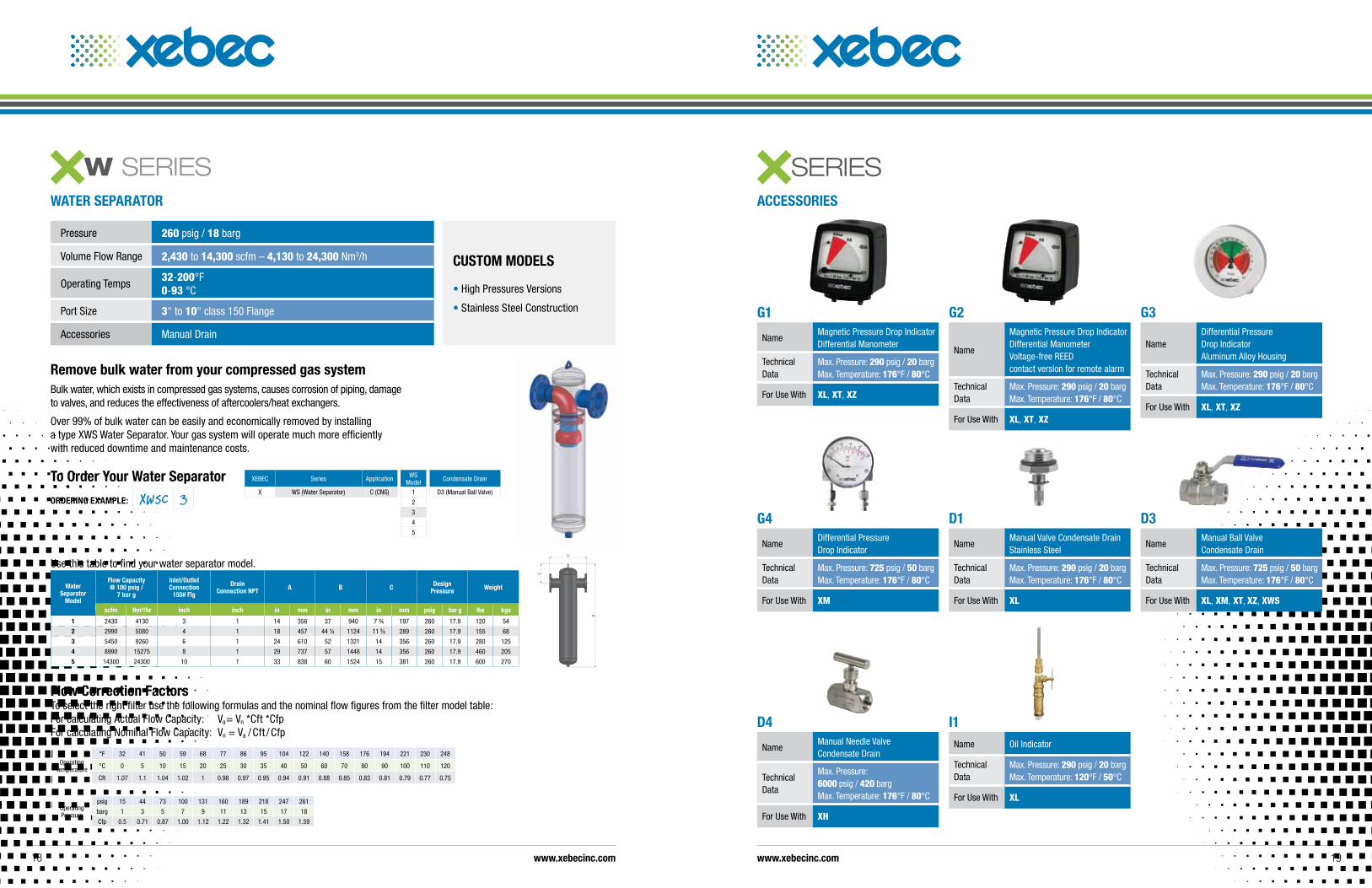
Remove bulk water from your compressed gas systemBulk water, which exists in compressed gas systems, causes corrosion of piping, damage to valves, and reduces the effectiveness of aftercoolers/heat exchangers.
Over 99% of bulk water can be easily and economically removed by installing a type XWS Water Separator. Your gas system will operate much more efficiently with reduced downtime and maintenance costs.
WATER SEPARATOR
ACCESSORIES
Pressure 260 psig / 18 barg
Volume Flow Range 2,430 to 14,300 scfm – 4,130 to 24,300 Nm3/h
Operating Temps 32-200°F 0-93 °C
Port Size 3" to 10" class 150 Flange
Accessories Manual Drain
CuSTOM MODELS
• High Pressures Versions
• Stainless Steel Construction
To Order your Water Separator
ORDERING EXAMPLE: XWSC 3XEBEC Series Application WS
Model Condensate Drain
X WS (Water Separator) C (CNG) 1 D3 (Manual Ball Valve)
2
3
4
5
Use this table to find your water separator model.
Water Separator
Model
Flow Capacity @ 100 psig /
7 bar g
Inlet/Outlet Connection
150# Flg
Drain Connection NPT A B C Design
Pressure Weight
scfm Nm³/hr inch inch in mm in mm in mm psig bar g lbs kgs
1 2430 4130 3 1 14 356 37 940 7 ¾ 197 260 17.9 120 54
2 2990 5080 4 1 18 457 44 ¼ 1124 11 3⁄8 289 260 17.9 155 68
3 5450 9260 6 1 24 610 52 1321 14 356 260 17.9 280 125
4 8990 15275 8 1 29 737 57 1448 14 356 260 17.9 460 205
5 14300 24300 10 1 33 838 60 1524 15 381 260 17.9 600 270
D4
NameManual Needle Valve Condensate Drain
Technical Data
Max. Pressure: 6000 psig / 420 barg Max. Temperature: 176°F / 80°C
For Use With XH
I1Name Oil Indicator
Technical Data
Max. Pressure: 290 psig / 20 barg Max. Temperature: 120°F / 50°C
For Use With XL
G1
NameMagnetic Pressure Drop Indicator Differential Manometer
Technical Data
Max. Pressure: 290 psig / 20 barg Max. Temperature: 176°F / 80°C
For Use With XL, XT, XZ
G2
Name
Magnetic Pressure Drop Indicator Differential Manometer Voltage-free REED contact version for remote alarm
Technical Data
Max. Pressure: 290 psig / 20 barg Max. Temperature: 176°F / 80°C
For Use With XL, XT, XZ
G3
NameDifferential Pressure Drop Indicator Aluminum Alloy Housing
Technical Data
Max. Pressure: 290 psig / 20 barg Max. Temperature: 176°F / 80°C
For Use With XL, XT, XZ
G4
NameDifferential Pressure Drop Indicator
Technical Data
Max. Pressure: 725 psig / 50 barg Max. Temperature: 176°F / 80°C
For Use With XM
D1
NameManual Valve Condensate Drain Stainless Steel
Technical Data
Max. Pressure: 290 psig / 20 barg Max. Temperature: 176°F / 80°C
For Use With XL
D3
NameManual Ball Valve Condensate Drain
Technical Data
Max. Pressure: 725 psig / 50 barg Max. Temperature: 176°F / 80°C
For Use With XL, XM, XT, XZ, XWS
Operating Pressure
psig 15 44 73 100 131 160 189 218 247 261
barg 1 3 5 7 9 11 13 15 17 18
Cfp 0.5 0.71 0.87 1.00 1.12 1.22 1.32 1.41 1.50 1.59
Operating Temperature
°F 32 41 50 59 68 77 86 95 104 122 140 158 176 194 221 230 248
°C 0 5 10 15 20 25 30 35 40 50 60 70 80 90 100 110 120
Cft 1.07 1.1 1.04 1.02 1 0.98 0.97 0.95 0.94 0.91 0.88 0.85 0.83 0.81 0.79 0.77 0.75
Flow Correction Factors To select the right filter use the following formulas and the nominal flow figures from the filter model table: For calculating Actual Flow Capacity: Va= Vn *Cft *Cfp For calculating Nominal Flow Capacity: Vn = Va / Cft / Cfp
www.xebecinc.com www.xebecinc.com18 19
www.xebecinc.com
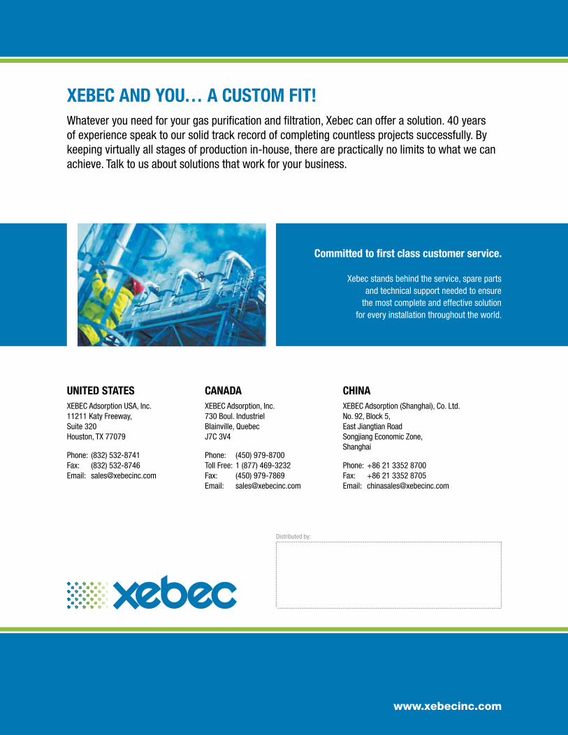
Committed to first class customer service.
Xebec stands behind the service, spare parts and technical support needed to ensure
the most complete and effective solution for every installation throughout the world.
XEBEC AND yOu… A CuSTOM FIT!Whatever you need for your gas purification and filtration, Xebec can offer a solution. 40 years of experience speak to our solid track record of completing countless projects successfully. By keeping virtually all stages of production in-house, there are practically no limits to what we can achieve. Talk to us about solutions that work for your business.
Distributed by:
CANADAXEBEC Adsorption, Inc. 730 Boul. Industriel Blainville, Quebec J7C 3V4
Phone: (450) 979-8700 Toll Free: 1 (877) 469-3232 Fax: (450) 979-7869 Email: [email protected]
CHINAXEBEC Adsorption (Shanghai), Co. Ltd. No. 92, Block 5, East Jiangtian Road Songjiang Economic Zone, Shanghai
Phone: +86 21 3352 8700 Fax: +86 21 3352 8705 Email: [email protected]
uNITED STATESXEBEC Adsorption USA, Inc. 11211 Katy Freeway, Suite 320 Houston, TX 77079
Phone: (832) 532-8741 Fax: (832) 532-8746 Email: [email protected]