Embed Size (px)
Citation preview
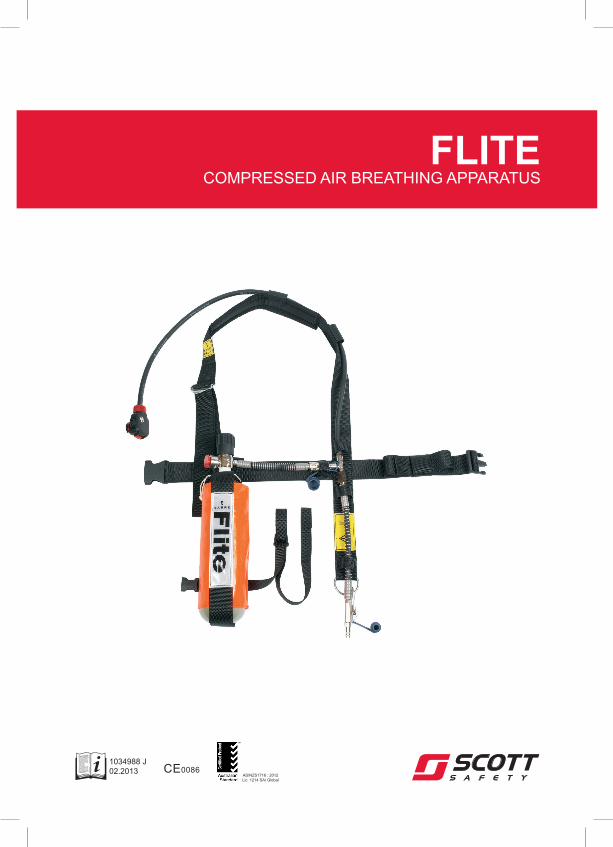
FLITECOMPRESSED AIR BREATHING APPARATUS
1034988 J02.2013 CE0086
AS/NZS1716 : 2012Lic. 1214 SAI Global

i
Contents
WARNINGS ...................................................................................................................................................... II 1. INTRODUCTION .................................................................................................................................... 1
1.1 ABBREVIATIONS USED IN THIS MANUAL ................................................................................ 1 1.2 LIMITATIONS OF USE ................................................................................................................. 1 1.3 BREATHABLE AIR ....................................................................................................................... 1 1.4 COMPRESSED AIR AIRLINE SUPPLIES ................................................................................... 2 1.5 TRAINING .................................................................................................................................... 2 1.6 SERVICING .................................................................................................................................. 2 1.7 PARTS IDENTIFICATION ............................................................................................................ 2 1.8 ORDERING PARTS AND ACCESSORIES ................................................................................. 3 1.9 WARRANTY ................................................................................................................................. 3 1.10 SELECTING APPARATUS FOR RESPIRATORY PROTECTION .............................................. 3
2. TECHNICAL DESCRIPTION ................................................................................................................. 4
2.1 GENERAL .................................................................................................................................... 4 2.2 FILTERS ....................................................................................................................................... 4 2.3 DEMAND VALVE ......................................................................................................................... 5 2.4 FACEMASKS ............................................................................................................................... 5
2.5 REDUCER/CYLINDER VALVE .................................................................................................... 5 2.6 CYLINDERS ................................................................................................................................. 5 2.7 QUALITY ATTRIBUTES............................................................................................................... 6 2.8 NOTIFIED BODIES ...................................................................................................................... 6
3. PRE-USE CHECKS................................................................................................................................ 7
3.1 FACEMASK .................................................................................................................................. 7 3.2 BANDOLIER................................................................................................................................. 8
4. DONNING AND OPERATING PROCEDURES ..................................................................................... 8 4.1 BANDOLIER................................................................................................................................. 8 4.2 FACEMASK .................................................................................................................................. 9 4.3 POSITIVE PRESSURE TEST ...................................................................................................... 9 4.4 FACE SEAL TEST ........................................................................................................................ 9 4.5 NEGATIVE PRESSURE TEST (FLITE WITH FILTER) .............................................................. 10 4.6 CHANGING FROM FILTER CANISTER TO AIRLINE ............................................................... 10 4.7 CHANGING FROM AIRLINE TO FILTER CANISTER ............................................................... 10
4.8 CHANGING FROM AIRLINE TO CYLINDER ............................................................................ 11 4.9 CHANGING FROM CYLINDER TO AIRLINE ............................................................................ 11
5. DOFFING THE APPARATUS .............................................................................................................. 11 6. CLEANING AND SCHEDULED MAINTENANCE............................................................................... 12
6.1 FACEMASK ................................................................................................................................ 12 6.2 DEMAND VALVE ....................................................................................................................... 13 6.3 BANDOLIER............................................................................................................................... 13
6.4 REDUCER, GAUGE AND CYLINDER ....................................................................................... 13 6.5 CHECK APPARATUS ................................................................................................................ 13 6.6 DEMAND VALVE ....................................................................................................................... 13 6.7 RECORD DETAILS OF CHECKS .............................................................................................. 14 6.8 STORAGE .................................................................................................................................. 14 6.9 MONTHLY MAINTENANCE....................................................................................................... 14 6.10 ANNUAL MAINTENANCE.......................................................................................................... 14
Registered Office: Scott Safety, Pimbo Road, West Pimbo, Skelmersdale, Lancashire, WN8 9RA, United Kingdom.
ii
WARNINGS
Please Read Carefully and Fully Understand
This manual is for use by personnel trained in the use and care of compressed air breathing apparatus (BA) and MUST NOT be used as a self-teaching guide by untrained users. Failure to understand or adhere to these instructions may result in injury or death.
Scott Safety have taken great care to ensure that the information contained within this manual is accurate, complete and clear. However, Training and Technical Support
Services will be pleased to clarify any points in the manual and answer any questions on Scott Safety breathing apparatus.
The following warnings are in accordance with certifying authority requirements and apply to the use of breathing apparatus in general:
Breathing apparatus users must be fully trained in the use and care of airline and self-contained,
compressed air breathing apparatus.
Ensure that the selection of the apparatus type is sufficient for the tasks being undertaken and the
hazards likely to be encountered. Please refer to National Regulations for guidance.
Adequate protection may not be provided in certain highly hazardous atmospheres.
The wearer must be aware of the length of time of the duration of the apparatus to ensure that they
have sufficient time to escape in the event of airline failure.
For potentially flammable or explosive atmospheres, anti-static hoses MUST be used.
Prior to use, check that the facemask is a good fit and that a good face seal can be achieved by the wearer. The wearing of beards, side-burns or spectacles may adversely affect the sealing of a
facemask to the wearer's face.
If the apparatus fails any of the pre-use checks it must be withdrawn from service and returned for
repair.
The quality of air used to supply and charge breathing apparatus must meet the requirements of EN
12021 : 1999 or AS/NZS1715 : 1994.
In Australia and New Zealand, ensure that your selection of respiratory protective devices conform
to the requirements of AS/NZS1715 : 1994.
The apparatus is not designed for use underwater.
Where FLITE has been contaminated by anything that may pose a threat to life or health, local statutes, health and safety guidance, site operating procedures or specialist advice for: doffing, de-contamination, cleaning or disposal of FLITE or its filters must be obtained and adhered to.
The harness must not be used as a vehicle seat restraint.
FLITE can be used at temperatures down to -6°C and stored between -30°C and +60°C.
Compressed air for use with BA must have a dew-point sufficiently low to prevent internal freezing.
DISCLAIMER
Failure to comply with these instructions or misuse of the apparatus may result in death, injury or material damage and invalidate any resulting warranty or insurance
claims.
COPYRIGHT
This manual must not be copied in part or in whole, or used for purposes other than its intended purpose without the written permission of Scott Safety.
FLITE
1
1. INTRODUCTION
1.1 ABBREVIATIONS USED IN THIS MANUAL
BA Breathing Apparatus
DV Demand Valve
kg Kilograms
HP High-pressure
mg Milligrams
ml Millilitres
m Metres
NRV Non Return Valve
ppm Parts per million
psi Pounds per Square Inch
1.2 LIMITATIONS OF USE
FLITE must only be used with Scott
Safety breathing apparatus facemasks.
FLITE must only be used by competent
personnel trained by Scott Safety or their approved agents.
FLITE must not be used with spectacle side arms, beards (or other facial hair), or clothing that may prevent the facemask
forming a good seal with the face.
1.3 BREATHABLE AIR
Air for compressed air BA may be natural
or synthetic. The composition of breathable air is given in EN 12021 : 1999 or AS/NZS1715 : 1994. The data
given or required in EN 12021 are valid for normal atmospheric pressure (one bar absolute, 20
oC). All percentage
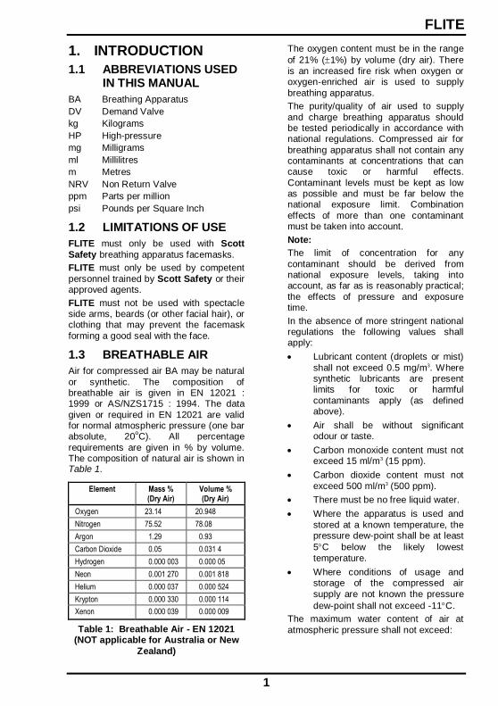
requirements are given in % by volume. The composition of natural air is shown in Table 1.
Element Mass % (Dry Air)
Volume % (Dry Air)
Oxygen 23.14 20.948
Nitrogen 75.52 78.08
Argon 1.29 0.93
Carbon Dioxide 0.05 0.031 4
Hydrogen 0.000 003 0.000 05
Neon 0.001 270 0.001 818
Helium 0.000 037 0.000 524
Krypton 0.000 330 0.000 114
Xenon 0.000 039 0.000 009
Table 1: Breathable Air - EN 12021 (NOT applicable for Australia or New
Zealand)
The oxygen content must be in the range
of 21% (1%) by volume (dry air). There
is an increased fire risk when oxygen or oxygen-enriched air is used to supply
breathing apparatus.
The purity/quality of air used to supply
and charge breathing apparatus should be tested periodically in accordance with national regulations. Compressed air for
breathing apparatus shall not contain any contaminants at concentrations that can cause toxic or harmful effects.
Contaminant levels must be kept as low as possible and must be far below the national exposure limit. Combination
effects of more than one contaminant must be taken into account.
Note:
The limit of concentration for any
contaminant should be derived from national exposure levels, taking into account, as far as is reasonably practical;
the effects of pressure and exposure time.
In the absence of more stringent national regulations the following values shall apply:
Lubricant content (droplets or mist)
shall not exceed 0.5 mg/m3. Where synthetic lubricants are present limits for toxic or harmful
contaminants apply (as defined above).
Air shall be without significant odour or taste.
Carbon monoxide content must not exceed 15 ml/m3 (15 ppm).
Carbon dioxide content must not
exceed 500 ml/m3 (500 ppm).
There must be no free liquid water.
Where the apparatus is used and
stored at a known temperature, the pressure dew-point shall be at least
5C below the likely lowest
temperature.
Where conditions of usage and storage of the compressed air
supply are not known the pressure
dew-point shall not exceed -11C.
The maximum water content of air at
atmospheric pressure shall not exceed:
FLITE
2
50 mg/m3 for 207 bar apparatus
35 mg/m3 for 300 bar apparatus
Note:
The water content of air supplied by a
compressor must not exceed 35 mg/m3.
Contaminants must be kept to a minimum
and must not exceed permissible exposure levels. Air filters must be suitable for the quality of air used and the
air must be tested periodically to ensure that the supply reaches these standards. The air must be free from the odour of oil
(odour threshold is 0.3 mg/m3).
The dew-point of air for compressed
airline BA must be sufficiently low to prevent internal freezing.
National regulations for compressed airline BA must be observed.
1.4 COMPRESSED AIR AIRLINE SUPPLIES
Air for use with compressed air airlines must conform to EN 12021 : 1999 or AS/NZS1715 : 1994.
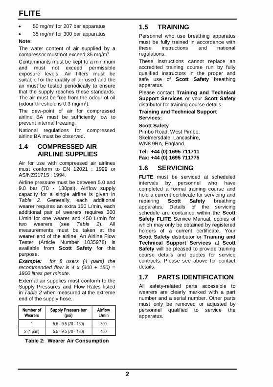
Airline pressure must be between 5.0 and 9.0 bar (70 - 130psi). Airflow supply capacity for a single airline is given in Table 2. Generally, each additional
wearer requires an extra 150 L/min, each additional pair of wearers requires 300
L/min for one wearer and 450 L/min for two wearers (see Table 2). All
measurements must be taken at the
wearer end of the airline. An Airline Flow Tester (Article Number 1035978) is available from Scott Safety for this
purpose.
Example: for 8 users (4 pairs) the
recommended flow is 4 x (300 + 150) = 1800 litres per minute.
External air supplies must conform to the Supply Pressures and Flow Rates listed in Table 2 when measured at the extreme
end of the supply hose.
Number of Wearers
Supply Pressure bar (psi)
Airflow L/min
1 5.5 - 9.5 (70 - 130) 300
2 (1 pair) 5.5 - 9.5 (70 - 130) 450
Table 2: Wearer Air Consumption
1.5 TRAINING
Personnel who use breathing apparatus
must be fully trained in accordance with these instructions and national regulations.
These instructions cannot replace an accredited training course run by fully
qualified instructors in the proper and safe use of Scott Safety breathing apparatus.
Please contact Training and Technical Support Services or your Scott Safety
distributor for training course details.
Training and Technical Support
Services:
Scott Safety
Pimbo Road, West Pimbo, Skelmersdale, Lancashire, WN8 9RA, England.
Tel: +44 (0) 1695 711711
Fax: +44 (0) 1695 711775
1.6 SERVICING
FLITE must be serviced at scheduled
intervals by personnel who have completed a formal training course and hold a current certificate for servicing and
repairing Scott Safety breathing apparatus. Details of the servicing schedule are contained within the Scott
Safety FLITE Service Manual, copies of which may only be obtained by registered holders of a current certificate. Your
Scott Safety distributor or Training and Technical Support Services at Scott Safety will be pleased to provide training
course details and quotes for service contracts. Please see above for contact details.
1.7 PARTS IDENTIFICATION
All safety-related parts accessible to wearers are clearly marked with a part
number and a serial number. Other parts must only be removed or adjusted by personnel qualified to service the
apparatus.
FLITE
3
1.8 ORDERING PARTS AND ACCESSORIES
Customer Services provide an efficient,
friendly customer contact point for ordering new apparatus, spare parts and accessories.
Customer Services:
Scott Safety
Pimbo Road, West Pimbo, Skelmersdale, Lancashire,
WN8 9RA, England.
Tel: +44 (0) 1695 711711
Fax: +44 (0) 1695 711775
1.9 WARRANTY
The products manufactured at our factories in Skelmersdale and Vaasa carry a warranty of 12 months (unless
stated otherwise) for parts, labour and return to site. The warranty period runs from the date of purchase by the end
user.
These products are warranted to be free
from defects in materials and workmanship at the time of delivery. Scott Safety will be under no liability for
any defect arising from wilful damage, negligence, abnormal working conditions, failure to follow the original
manufacturer’s instructions, misuse or unauthorised alteration or repair.
Evidence of purchase date will need to be provided for any claims arising during the warranty period. All warranty claims must
be directed through Scott Safety Customer Services and in accordance with our sales return procedure.
1.10 SELECTING APPARATUS FOR RESPIRATORY PROTECTION
When selecting respiratory protective equipment the following factors must be
considered:
Hazards likely to be encountered
and their effect on the wearer.
Physical and emotional stress and their effect on wearer breathing
rate.
The type of respiratory protection
required.
The oxygen level may fall below
19%.
There are high levels of toxic hazard.
Where any of the above are present, a higher level of respiratory protection
should be selected.
When selecting respiratory protective
apparatus, refer to EN 529 : 2005 or AS/NZS1715 : 1994.
FLITE
4
2. TECHNICAL DESCRIPTION
2.1 GENERAL
FLITE is a positive pressure compressed air, airline, breathing apparatus (BA). It
can be used with either:
(a) A compressed air cylinder to
enable wearers to leave hazardous areas safely in the event of airline failure, or
(b) A facemask that can be fitted with a suitable Scott Safety particulate
filter, to be used when entering or leaving the hazard area with the airline disconnected.
In the latter mode the facemask functions as a negative pressure device.
The supply airline hose connects to a CEN connector that supplies the
facemask-mounted demand valve via a length of medium pressure air hose.
WARNING:
FLITE must not be used in oxygen
deficient atmospheres whilst disconnected from the airline supply and with the cylinder not in use.
Non Return Valves (NRV) in the pneumatics seal the air inlet from the
airline and the cylinder when either are not in use. The apparatus MUST be used with a cylinder, or an airline, or both.
The apparatus comprises a full facemask, a Demand Valve (DV), and a pigtail with
CEN coupling for attaching the supply airline.
There are three cylinder options that can be provided with the apparatus.
The air supply specification for FLITE is detailed below:
Maximum Cylinder Duration 10, 13 or 15 minutes
Maximum Airline Length 90 metres
Air Supply Specification
The flame-resistant bandolier relieves the pull of the airline hose and when a
compressed air cylinder is fitted, supports the cylinder bag.
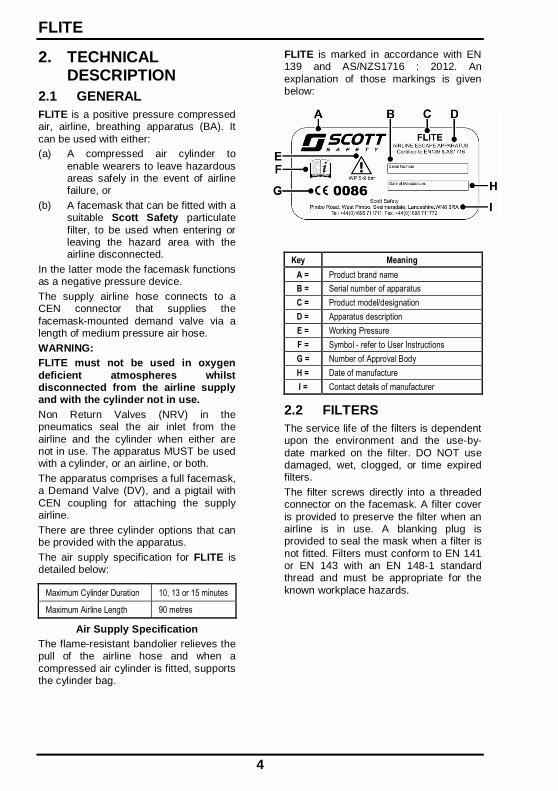
FLITE is marked in accordance with EN 139 and AS/NZS1716 : 2012. An
explanation of those markings is given below:
Key Meaning
A = Product brand name
B = Serial number of apparatus
C = Product model/designation
D = Apparatus description
E = Working Pressure
F = Symbol - refer to User Instructions
G = Number of Approval Body
H = Date of manufacture
I = Contact details of manufacturer
2.2 FILTERS
The service life of the filters is dependent upon the environment and the use-by-
date marked on the filter. DO NOT use damaged, wet, clogged, or time expired filters.
The filter screws directly into a threaded connector on the facemask. A filter cover
is provided to preserve the filter when an airline is in use. A blanking plug is provided to seal the mask when a filter is
not fitted. Filters must conform to EN 141 or EN 143 with an EN 148-1 standard thread and must be appropriate for the
known workplace hazards.

FLITE
5
2.3 DEMAND VALVE
Airflow into the facemask is controlled by the DV, which is attached to the facemask by a quick-fit connection. The
DV can be closed by a reset button to enable the facemask to be removed without loss of air to the atmosphere.
When the DV is next used the first breath taken by the wearer opens the DV automatically.
The bypass knob enables the wearer to open an unregulated flow of air into the
facemask.
2.4 FACEMASKS
FLITE is approved for use with
PanaSeal, PanaVisor, Vision 3 and Promask PP full facemasks.
All of which have the following features:
Conformance with EN 136 and
AS/NZS1716 : 2012.
Speech diaphragm.
Ori-nasal inner mask to minimise the carbon dioxide dead space and
prevent visor misting.
Polycarbonate visor.
Fully adjustable, five-point web, or
net head harness options.
Left quick fit DV connector.
Reflex face seal.
PanaSeal is the standard facemask. It is available in non-dermatitic silicone or
neoprene and may be fitted with a microphone for a personal radio.
PanaVisor is similar to PanaSeal, but its larger size makes it more suitable for larger face sizes.
Vision 3 is available in non-dermatitic silicone. It has a large visor, which
provides the wearer with a wider range of vision.
Promask PP is moulded in hypo-allergenic, black ProcompTM with a soft silicone inner mask.
2.5 REDUCER/CYLINDER VALVE
The reducer/cylinder valve is a combined cylinder valve and pressure reducer.
When the handwheel is opened, air flows from the cylinder, through the reducer to the facemask demand valve.
The reducer is a spring and piston device with an integral Pressure Relief Valve
(PRV) that protects the medium pressure circuit from over-pressurisation.
The pressure gauge indicates the current cylinder pressure.
2.6 CYLINDERS
When cylinders are provided they may be:
10 minute cylinder (CYL-FLITE-10):
Free air capacity: 400 litres
Charging pressure: 207 bar
Material: Alloy Steel
Specification: CE
Duration at 40 L/min: 10 minutes
Weight (charged): 3.8Kg
10 minute cylinder (CYL-FLITE-10-AUS/NZ):
Free air capacity: 440 litres
Charging pressure: 207 bar
Material: Alloy Steel
Specification: Work Cover
Duration at 40 L/min: 10 minutes
Weight (charged): 4.2Kg
10 minute cylinder (CYL-FLITE-SL):
Free air capacity: 540 litres
Charging pressure: 300 bar
Material: Carbon Fibre / Aluminium
Specification: HSE-AL-FW2 & TUV
Duration at 40 L/min: 13 minutes
Weight (charged): 4.3Kg

FLITE
6
15 minute cylinder (CYL-FLITE-15):
Free air capacity: 600 litres
Charging pressure: 207 bar
Material: Alloy Steel
Specification: CE
Duration at 40 L/min: 15 minutes
Weight (charged): 4.7Kg
15 minute cylinder (CYL-FLITE-15-AUS/NZ):
Free air capacity: 660 litres
Charging pressure: 207 bar
Material: Alloy Steel
Specification: Work Cover
Duration at 40 L/min: 15 minutes
Weight (charged): 5.1Kg
Carbon fibre/aluminium cylinders should be used with apparatus that is to be used for full shift periods. Steel cylinders
should NOT be used for full shift working.
When changing from airline to cylinder supply, the non-return valve in the supply
airline protects the airline from contamination, while a second, in the FLITE air hose prevents cylinder air loss.
2.7 QUALITY ATTRIBUTES
FLITE is 'CE' marked in accordance with EEC Directive EC/686/1986.
It is approved to European Standard EN 139 : 1993 (Respiratory Protective
Devices - Compressed Airline Breathing Apparatus). AS/NZS 1716 : 2012 (Respiratory Protective Devices).
Facemasks are approved to EN 136 and AS/NZS1716 : 2012.
Scott Safety is quality assurance approved to ISO 9001 : 2000.
2.8 NOTIFIED BODIES
Inspec International Limited (No. 0194)
56 Leslie Hough Way, Salford, Greater Manchester,
M6 6AJ, England.
BSI (0086) Kitemark Court,
Davy Ave, Knowlhill, Milton Keynes,
MK5 8PP. England.
SAI Global 286 Sussex Street,
Sydney, NSW 2000, Australia.
Lic. No 1214.
FLITE
7
3. PRE-USE CHECKS
3.1 FACEMASK
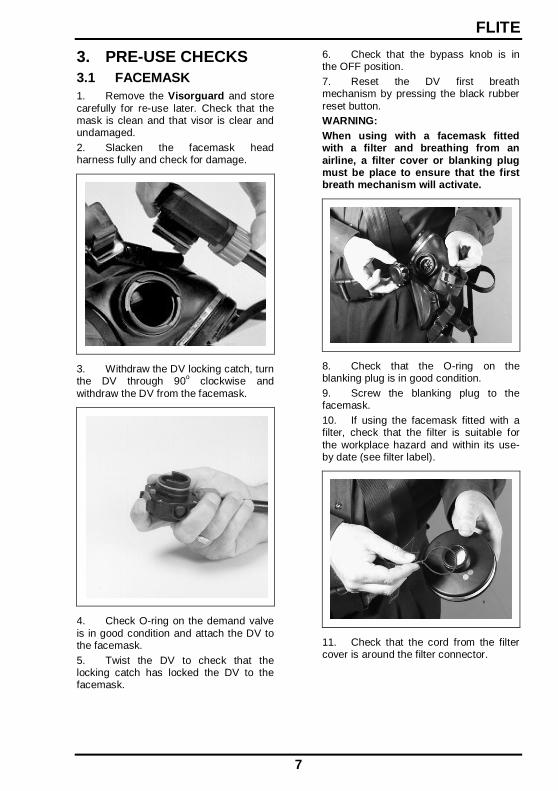
1. Remove the Visorguard and store
carefully for re-use later. Check that the mask is clean and that visor is clear and undamaged.
2. Slacken the facemask head harness fully and check for damage.
3. Withdraw the DV locking catch, turn the DV through 90
o clockwise and
withdraw the DV from the facemask.
4. Check O-ring on the demand valve
is in good condition and attach the DV to the facemask.
5. Twist the DV to check that the locking catch has locked the DV to the facemask.
6. Check that the bypass knob is in the OFF position.
7. Reset the DV first breath mechanism by pressing the black rubber
reset button.
WARNING:
When using with a facemask fitted with a filter and breathing from an
airline, a filter cover or blanking plug must be place to ensure that the first breath mechanism will activate.
8. Check that the O-ring on the blanking plug is in good condition.
9. Screw the blanking plug to the facemask.
10. If using the facemask fitted with a filter, check that the filter is suitable for
the workplace hazard and within its use-by date (see filter label).
11. Check that the cord from the filter cover is around the filter connector.
FLITE
8
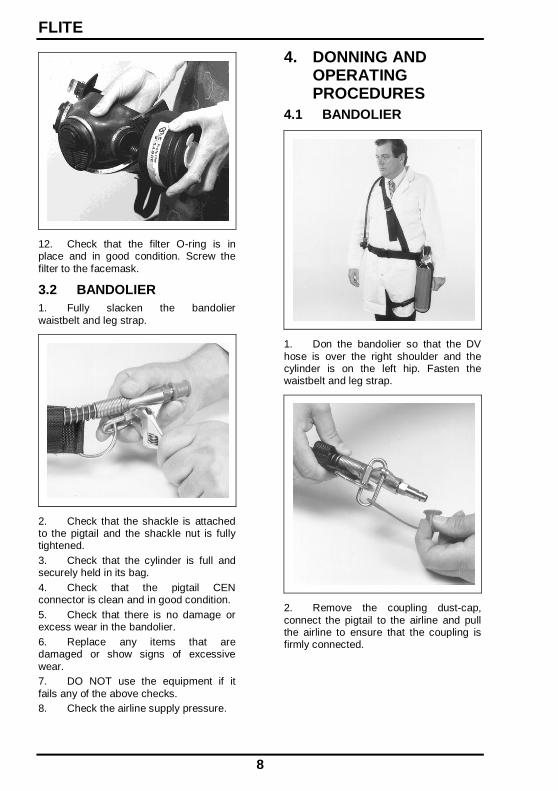
12. Check that the filter O-ring is in place and in good condition. Screw the
filter to the facemask.
3.2 BANDOLIER
1. Fully slacken the bandolier
waistbelt and leg strap.
2. Check that the shackle is attached to the pigtail and the shackle nut is fully tightened.
3. Check that the cylinder is full and securely held in its bag.
4. Check that the pigtail CEN connector is clean and in good condition.
5. Check that there is no damage or excess wear in the bandolier.
6. Replace any items that are damaged or show signs of excessive
wear.
7. DO NOT use the equipment if it
fails any of the above checks.
8. Check the airline supply pressure.
4. DONNING AND OPERATING PROCEDURES
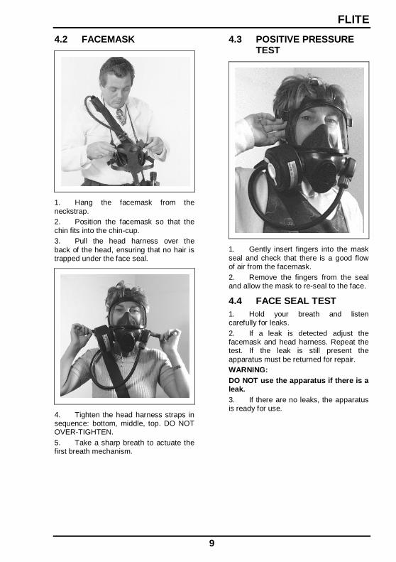
4.1 BANDOLIER
1. Don the bandolier so that the DV
hose is over the right shoulder and the cylinder is on the left hip. Fasten the waistbelt and leg strap.
2. Remove the coupling dust-cap,
connect the pigtail to the airline and pull the airline to ensure that the coupling is firmly connected.
FLITE
9
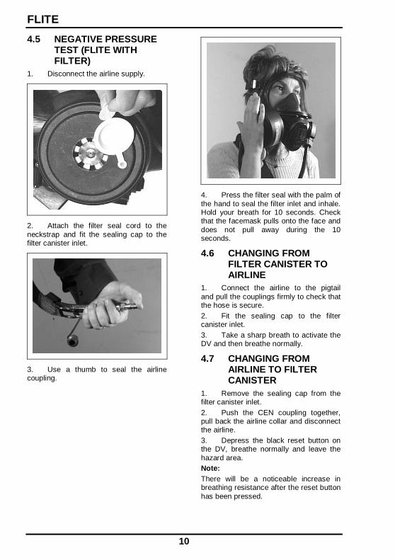
4.2 FACEMASK
1. Hang the facemask from the
neckstrap.
2. Position the facemask so that the
chin fits into the chin-cup.
3. Pull the head harness over the
back of the head, ensuring that no hair is trapped under the face seal.
4. Tighten the head harness straps in sequence: bottom, middle, top. DO NOT OVER-TIGHTEN.
5. Take a sharp breath to actuate the first breath mechanism.
4.3 POSITIVE PRESSURE TEST
1. Gently insert fingers into the mask
seal and check that there is a good flow of air from the facemask.
2. Remove the fingers from the seal and allow the mask to re-seal to the face.
4.4 FACE SEAL TEST
1. Hold your breath and listen carefully for leaks.
2. If a leak is detected adjust the facemask and head harness. Repeat the test. If the leak is still present the
apparatus must be returned for repair.
WARNING:
DO NOT use the apparatus if there is a leak.
3. If there are no leaks, the apparatus is ready for use.
FLITE
10
4.5 NEGATIVE PRESSURE TEST (FLITE WITH FILTER)
1. Disconnect the airline supply.
2. Attach the filter seal cord to the
neckstrap and fit the sealing cap to the filter canister inlet.
3. Use a thumb to seal the airline coupling.
4. Press the filter seal with the palm of
the hand to seal the filter inlet and inhale. Hold your breath for 10 seconds. Check that the facemask pulls onto the face and
does not pull away during the 10 seconds.
4.6 CHANGING FROM FILTER CANISTER TO AIRLINE
1. Connect the airline to the pigtail
and pull the couplings firmly to check that the hose is secure.
2. Fit the sealing cap to the filter canister inlet.
3. Take a sharp breath to activate the DV and then breathe normally.
4.7 CHANGING FROM AIRLINE TO FILTER CANISTER
1. Remove the sealing cap from the filter canister inlet.
2. Push the CEN coupling together, pull back the airline collar and disconnect the airline.
3. Depress the black reset button on the DV, breathe normally and leave the
hazard area.
Note:
There will be a noticeable increase in breathing resistance after the reset button
has been pressed.
FLITE
11
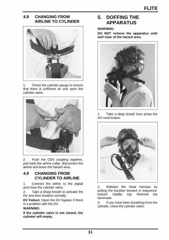
4.8 CHANGING FROM AIRLINE TO CYLINDER
1. Check the cylinder gauge to ensure that there is sufficient air and open the
cylinder valve.
2. Push the CEN coupling together,
pull back the airline collar, disconnect the airline and leave the hazard area.
4.9 CHANGING FROM CYLINDER TO AIRLINE
1. Connect the airline to the pigtail and close the cylinder valve.
2. Take a sharp breath to activate the
DV and then breathe normally.
DV Failure: Open the DV bypass if there
is a problem with the DV.
WARNING:
If the cylinder valve is not closed, the cylinder will empty.
5. DOFFING THE APPARATUS
WARNING:
DO NOT remove the apparatus until well clear of the hazard area.
1. Take a deep breath then press the
DV reset button.
2. Release the head harness by
pulling the buckles forward in sequence: bottom, middle, top. Remove the facemask.
3. If you have been breathing from the cylinder, close the cylinder valve.
FLITE
12
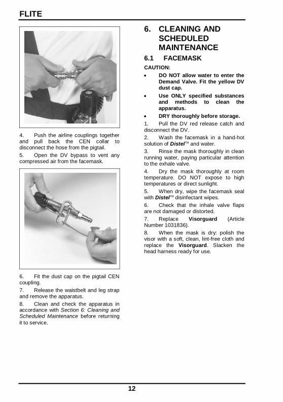
4. Push the airline couplings together and pull back the CEN collar to disconnect the hose from the pigtail.
5. Open the DV bypass to vent any compressed air from the facemask.
6. Fit the dust cap on the pigtail CEN coupling.
7. Release the waistbelt and leg strap and remove the apparatus.
8. Clean and check the apparatus in accordance with Section 6: Cleaning and Scheduled Maintenance before returning
it to service.
6. CLEANING AND SCHEDULED MAINTENANCE
6.1 FACEMASK
CAUTION:
DO NOT allow water to enter the
Demand Valve. Fit the yellow DV dust cap.
Use ONLY specified substances and methods to clean the
apparatus.
DRY thoroughly before storage.
1. Pull the DV red release catch and
disconnect the DV.
2. Wash the facemask in a hand-hot
solution of DistelTM and water.
3. Rinse the mask thoroughly in clean
running water, paying particular attention to the exhale valve.
4. Dry the mask thoroughly at room temperature. DO NOT expose to high temperatures or direct sunlight.
5. When dry, wipe the facemask seal with DistelTM disinfectant wipes.
6. Check that the inhale valve flaps are not damaged or distorted.
7. Replace Visorguard (Article Number 1031836).
8. When the mask is dry: polish the visor with a soft, clean, lint-free cloth and
replace the Visorguard. Slacken the head harness ready for use.

FLITE
13
6.2 DEMAND VALVE
1. Fit the yellow DV dustcap (Article Number 1033545) over the DV inlet, immerse the bypass knob in running
water and operate the bypass knob several times.
2. Clean the outer surfaces with a clean, lint-free cloth. Persistent marks can be removed with a clean, lint-free cloth
moistened with a solution of DistelTM and warm water.
3. Check that both the locking catch and bypass knob move freely. If either does not move freely, the DV must be
serviced.
6.3 BANDOLIER
1. Brush dirt from the bandolier using a stiff brush.
2. If heavily soiled, the bandolier can be soaked in a solution of DistelTM and warm water for one hour and then
scrubbed with a stiff brush.
3. Dry the bandolier thoroughly in a
well-ventilated room away from direct heat and sunlight.
6.4 REDUCER, GAUGE AND CYLINDER
1. Dust the exterior of the equipment
with a clean lint-free cloth.
2. Use a lint-free cloth moistened in
DistelTM to clean off persistent marks.
Note:
DistelTM cleansing and disinfecting solution is available from Scott Safety in
both 1 litre and 5 litre containers under Article Numbers 2008247 and 2008248 respectively.
Suitable pump dispensers are also available under Article Numbers 1017672
(1 litre) and 1017670 (5 litres).
DistelTM disinfecting wipes are available
from Scott Safety in packs of 20 sachets, (Article Number 2004225), or drums of 100 wipes, (Article Number 1017652).
6.5 CHECK APPARATUS
1. Check the apparatus thoroughly for signs of damage and wear. If any of the
components are damaged, the apparatus must be returned, with an explanatory note, for servicing.
2. Check that the cylinder valve handwheel turns smoothly and does not
stick.
3. Check that the cylinder is full. If it is
not, withdraw FLITE from service and recharge the cylinder.
6.6 DEMAND VALVE
1. Operate the locking catch several times to check that it does not stick. The locking catch should spring back to its
original position without sticking.
FLITE
14
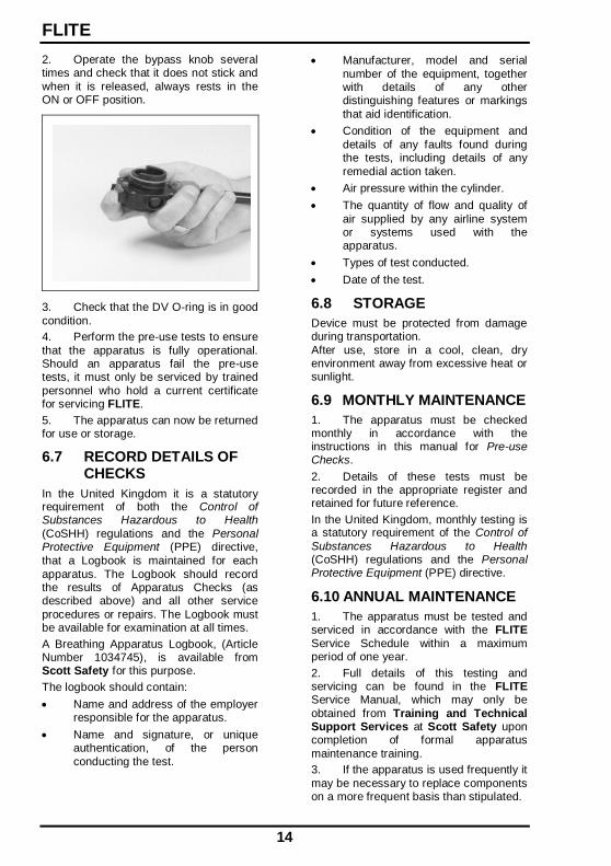
2. Operate the bypass knob several times and check that it does not stick and
when it is released, always rests in the ON or OFF position.
3. Check that the DV O-ring is in good
condition.
4. Perform the pre-use tests to ensure
that the apparatus is fully operational. Should an apparatus fail the pre-use tests, it must only be serviced by trained
personnel who hold a current certificate for servicing FLITE.
5. The apparatus can now be returned for use or storage.
6.7 RECORD DETAILS OF CHECKS
In the United Kingdom it is a statutory requirement of both the Control of Substances Hazardous to Health
(CoSHH) regulations and the Personal Protective Equipment (PPE) directive,
that a Logbook is maintained for each
apparatus. The Logbook should record the results of Apparatus Checks (as described above) and all other service
procedures or repairs. The Logbook must be available for examination at all times.
A Breathing Apparatus Logbook, (Article Number 1034745), is available from Scott Safety for this purpose.
The logbook should contain:
Name and address of the employer responsible for the apparatus.
Name and signature, or unique authentication, of the person
conducting the test.
Manufacturer, model and serial
number of the equipment, together with details of any other distinguishing features or markings
that aid identification.
Condition of the equipment and
details of any faults found during the tests, including details of any
remedial action taken.
Air pressure within the cylinder.
The quantity of flow and quality of
air supplied by any airline system or systems used with the apparatus.
Types of test conducted.
Date of the test.
6.8 STORAGE
Device must be protected from damage during transportation.
After use, store in a cool, clean, dry environment away from excessive heat or sunlight.
6.9 MONTHLY MAINTENANCE
1. The apparatus must be checked monthly in accordance with the instructions in this manual for Pre-use Checks.
2. Details of these tests must be recorded in the appropriate register and retained for future reference.
In the United Kingdom, monthly testing is a statutory requirement of the Control of
Substances Hazardous to Health (CoSHH) regulations and the Personal Protective Equipment (PPE) directive.
6.10 ANNUAL MAINTENANCE
1. The apparatus must be tested and serviced in accordance with the FLITE
Service Schedule within a maximum period of one year.
2. Full details of this testing and servicing can be found in the FLITE Service Manual, which may only be
obtained from Training and Technical Support Services at Scott Safety upon completion of formal apparatus
maintenance training.
3. If the apparatus is used frequently it
may be necessary to replace components on a more frequent basis than stipulated.


Tel: +44 (0) 1695 711711Fax: +44 (0) 1695 711775
Scott SafetyPimbo Road, West Pimbo,Skelmersdale, Lancashire,
WN8 9RA, England
© 2011 Scott Safety. All rights reserved. SCOTT, the SCOTT SAFETY Logo, Scott Health and Safety, Flite are registered and/or unregistered marks of Scott Technologies, Inc. or its affiliates.English (GB)