Embed Size (px)
Citation preview
INDIANA DEPARTMENT OF TRANSPORTATION—2013 DESIGN MANUAL
CHAPTER 304
Comprehensive Pavement Analyses
Design
Memorandum Revision
Date Sections Affected
13-01 Jan. 2013 52-11.01 13-18 Oct. 2013 52-8.03 & 52-8.03(01) 14-06 Apr. 2014 Ch. 52 superseded by Ch. 304 16-25 Jun. 2016 Figure 304-15A & 304-15B 16-26 Jun. 2016 Figure 304-18A 18-01 Feb. 2018 304-5.02
Page 2 2013 Indiana Design Manual, Ch. 304
TABLE OF CONTENTS
TABLE OF CONTENTS ................................................................................................................ 2
LIST OF FIGURES ........................................................................................................................ 6
304-1.0 INTRODUCTION ............................................................................................................ 8
304-2.0 HISTORY ......................................................................................................................... 8
304-3.0 ABBREVIATIONS .......................................................................................................... 9
304-4.0 INDOT PAVEMENT ANALYSES PHILOSOPHY ..................................................... 11
304-5.0 PAVEMENT DESIGN DEVELOPMENT .................................................................... 12 304-5.01 INDOT Pavement Design Process ........................................................................... 13
304-5.01(01) INDOT Preliminary Pavement Proposal ....................................................... 14 304-5.01(02) INDOT Final Pavement Design ..................................................................... 15
304-5.02 Local Public Agency (LPA) Pavement Design Process [Rev. Feb. 2018] ................ 17 304-5.02(01) LPA Final Pavement Design [Rev. Feb. 2018] ............................................... 17 304-5.02(02) LPA Final Pavement Design for State and NHS Routes [Rev. Feb. 2018] .... 17 304-5.02(03) Std Pavement Designs for Low Vol. Roads and Trails [Rev. Feb. 2018] ...... 18 304-5.02(04) Notification of Pavement Design Approval [Rev. Feb. 2018] ........................ 18
304-6.0 PAVEMENT PROJECT CATEGORIES ....................................................................... 18 304-6.01 New Alignment ........................................................................................................ 19 304-6.02 Pavement Reconstruction ......................................................................................... 19 304-6.03 Pavement Rehabilitation ........................................................................................... 19
304-6.03(01) Structural Overlay .......................................................................................... 20 304-6.03(02) PCCP Rubblization and HMA Overlay ......................................................... 20 304-6.03(03) PCCP Cracking and Seating and HMA Overlay ........................................... 20 304-6.03(04) Unbonded PCCP Overlay over Old PCCP .................................................... 21 304-6.03(05) Full Depth Pavement Reclamation ................................................................ 21
304-6.04 Preventive Maintenance ........................................................................................... 23 304-6.04(01) Surface Treatment .......................................................................................... 23 304-6.04(02) Mill and Fill Overlay Treatment .................................................................... 23 304-6.04(03) In-Place Recycling ......................................................................................... 24
304-7.0 PAVEMENT TYPE SELECTION ................................................................................. 25
304-8.0 PAVEMENT TYPES ..................................................................................................... 26 304-8.01 Aggregate Pavement ................................................................................................. 26 304-8.02 Asphalt Pavement ..................................................................................................... 26
304-8.02(01) HMA / SMA Surface ..................................................................................... 29 304-8.02(02) HMA Intermediate ......................................................................................... 29
2013 Indiana Design Manual, Ch. 304 Page 3
304-8.02(03) HMA Base...................................................................................................... 29 304-8.02(04) HMA Open Graded Drainage Layer .............................................................. 29 304-8.02(05) Compacted Aggregate Base ........................................................................... 30
304-8.03 Portland Cement Concrete Pavement ....................................................................... 30 304-8.04 Composite Pavement ................................................................................................ 31
304-9.0 PAVEMENT DISTRESSES .......................................................................................... 31
304-10.0 PAVEMENT MILLING............................................................................................... 33 304-10.01 Asphalt or PCCP Scarification Milling .................................................................. 33 304-10.02 Asphalt or PCCP Profile Milling ............................................................................ 34 304-10.03 Approach Milling ................................................................................................... 34 304-10.04 Asphalt or PCCP Milling ........................................................................................ 34 304-10.05 Asphalt Overlay Removal ...................................................................................... 35 304-10.06 Transition Milling ................................................................................................... 35
304-11.0 PAVEMENT PATCHING ........................................................................................... 35 304-11.01 PCCP Patching, Full Depth .................................................................................... 35 304-11.02 HMA Patching ........................................................................................................ 38 304-11.03 Composite Patching ................................................................................................ 38
304-12.0 PAVEMENT WIDENING ........................................................................................... 38 304-12.01 Widening with HMA .............................................................................................. 39 304-12.02 Widening with PCC Base ....................................................................................... 39 304-12.03 Widening for Composite Pavements ...................................................................... 40
304-13.0 PAVEMENT TESTING ............................................................................................... 40 304-13.01 Falling-Weight-Deflectometer (FWD) Testing ...................................................... 40 304-13.02 Ground Penetrating Radar (GPR) Testing .............................................................. 41 304-13.03 Pavement Coring .................................................................................................... 41 304-13.04 Pavement Friction ................................................................................................... 42
304-14.0 MECHANISTIC EMPERICAL PAVEMENT DESIGN GUIDE ............................... 42 304-14.01 MEPDG General Inputs Using AASHTOWare Pavement ME Design software .. 43 304-14.02 Flexible Pavement Layer Design ............................................................................ 47 304-14.03 Rigid Pavement Layer Design ................................................................................ 49 304-14.04 Non-Stabilized Base Pavement Layer Design ........................................................ 52 304-14.05 Subgrade Treatment Layer Design ......................................................................... 54 304-14.06 Aggregate Subgrade Treatment Layer Design ....................................................... 56 304-14.07 Chemically Stabilized Pavement Layer Design ..................................................... 56 304-14.08 Overlay Design ....................................................................................................... 58
304-15.0 HMA PAVEMENTS AND PAY ITEMS .................................................................... 61 304-15.01 Performance Grade (PG) Binder ............................................................................ 62
Page 4 2013 Indiana Design Manual, Ch. 304
304-15.02 HMA Shoulders ...................................................................................................... 63 304-15.03 HMA for Approaches ............................................................................................. 63 304-15.04 Composite Pavement Rehabilitation ...................................................................... 64
304-16.0 PCC PAVEMENT AND PAY ITEMS ........................................................................ 64 304-16.01 PCCP Preventive Maintenance Treatment (CPR) .................................................. 65 304-16.02 Continuously Reinforced Concrete Pavement (CRCP) .......................................... 66
304-16.02(01) CRCP Design ............................................................................................... 66 304-16.02(02) CRCP Reinforcement ................................................................................... 67 304-16.02(03) CRCP Edge Support/Shoulders ................................................................... 69 304-16.02(04) CRCP End Treatments ................................................................................. 69 304-16.02(05) CRCP Concrete Curing ................................................................................ 69
304-17.0 MISCELLANEOUS PAVEMENT PROJECT ELEMENTS ...................................... 70 304-17.01 Subgrade ................................................................................................................. 70 304-17.02 Temporary Pavement .............................................................................................. 70 304-17.03 Driveways ............................................................................................................... 71 304-17.04 U-Turn Median Opening ........................................................................................ 71 304-17.05 Public Road Approach ............................................................................................ 71 304-17.06 Bridge Deck Overlay .............................................................................................. 71 304-17.07 Seal Coat ................................................................................................................. 71 304-17.08 Prime Coat .............................................................................................................. 71 304-17.09 Tack Coat ................................................................................................................ 72 304-17.10 Base Seal ................................................................................................................ 72 304-17.11 Curbs and Shoulders ............................................................................................... 72 304-17.12 Reinforced-Concrete Bridge Approach (RCBA) ................................................... 72
304-18.0 UNDERDRAINS.......................................................................................................... 73 304-18.01 Definitions .............................................................................................................. 73 304-18.02 Existing Underdrain Perpetuation .......................................................................... 75 304-18.03 Underdrain Warrants .............................................................................................. 75 304-18.04 Design Criteria ........................................................................................................ 76
304-18.04(01) Slope ............................................................................................................ 76 304-18.04(02) Size ............................................................................................................... 76 304-18.04(03) Outlet Spacing .............................................................................................. 76 304-18.04(04) Location ....................................................................................................... 77 304-18.04(05) Backfill ......................................................................................................... 78 304-18.04(06) Outlet Protector ............................................................................................ 78 304-18.04(07) Geotextiles for Underdrain........................................................................... 78 304-18.04(08) Video Inspection .......................................................................................... 79
304-18.05 Contract Document Preparation ............................................................................. 79
2013 Indiana Design Manual, Ch. 304 Page 5
304-18.05(01) Plans ............................................................................................................. 79 304-18.05(02) Specifications ............................................................................................... 80 304-18.05(03) Standard Drawings ....................................................................................... 80 304-18.05(04) Pay Items ...................................................................................................... 81
304-19.0 PREVENTIVE MAINTENANCE ............................................................................... 81 304-19.01 HMA Pavement PM Treatments ............................................................................. 82 304-19.02 PCCP PM Treatments ............................................................................................. 89
304-20.0 LIFE-CYCLE COST ANALYSIS (LCCA) ................................................................. 91 304-20.01 General Requirements ............................................................................................ 91 304-20.02 Definitions .............................................................................................................. 92
304-20.02(01) Analysis Period ............................................................................................ 92 304-20.02(02) Discount Rate ............................................................................................... 92 304-20.02(03) Equivalent Uniform Annual Cost (EUAC) .................................................. 92 304-20.02(04) LCCA Design Life ....................................................................................... 93 304-20.02(05) Life-Cycle Cost ............................................................................................ 93 304-20.02(06) Present Worth (PW) ..................................................................................... 94 304-20.02(07) Salvage Value (SV) ...................................................................................... 95
304-20.03 Analysis Steps ........................................................................................................ 95 304-20.03(01) HMA Pavement............................................................................................ 95 304-20.03(02) PCCP ............................................................................................................ 96
304-21.0 TYPICAL PAVEMENT SECTIONS .......................................................................... 97 304-21.01 HMA Pavement ...................................................................................................... 97 304-21.02 PCC Pavement ........................................................................................................ 97 304-21.03 Miscellaneous Pavement Sections and Details ....................................................... 97
304-22.0 PAVEMENT DESIGN REQUEST AND INSTRUCTIONS ...................................... 98
FIGURES ...................................................................................................................................... 99
Page 6 2013 Indiana Design Manual, Ch. 304
LIST OF FIGURES Figure Title 304-14A Pavement Design Life 304-14B Performance Criteria for New or Rehabilitation HMA Pavement 304-14C Performance Criteria for New or Rehabilitation Concrete Pavement 304-14D MEPDG General Input Values for Asphalt Pavement 304-15A ESAL Category for QC/QA-HMA Mixtures [Rev. Jun. 2016] 304-15B Mixture Type for HMA Mixtures [Rev. Jun. 2016] 304-18A Outlet Protector Slope Limits [Rev. Jun. 2016] 304-18B Video Inspection Contract Quantities 304-19A HMA Preventive Maintenance Treatments 304-19B PCCP Preventive Maintenance Treatments 304-21A Full-Depth HMA Pavement with Full-Depth Shoulder with Underdrain 304-21B Full-Depth HMA Pavement with Full-Depth Shoulder without Underdrain 304-21C Full-Depth HMA Pavement with HMA on Compacted Aggregate Shoulder with
Underdrain 304-21D Typical Full-Depth HMA Pavement with Shoulder 304-21E Full-Depth HMA Pavement with HMA on Compacted Aggregate Shoulder without
Underdrain 304-21F HMA on Compacted Aggregate Pavement 304-21G Typical HMA Pavement on Compacted Aggregate 304-21H Full-Depth HMA Ramp 304-21 I Underdrain for HMA Pavement with Full-Depth HMA Shoulder 304-21J Underdrain for Full-Depth HMA Pavement with HMA on Compacted Aggregate
Shoulder 304-21K Concrete Curb and Gutter Section for HMA Pavement with Underdrain 304-21L Concrete Curb and Gutter Section for HMA Pavement without Underdrain 304-21M Concrete Curb and Gutter Section for HMA or PCCP Pavement without Underdrain 304-21N Modified Concrete Curb and Gutter Section for HMA or PCCP Pavement on
Compacted Aggregate without Underdrain 304-21 O Modified Concrete Curb and Gutter Section for HMA or PCCP Pavement with
Underdrain 304-21P PCCP Section with PCC Shoulder 304-21Q PCCP Section with HMA Outside Shoulder 304-21R PCCP with Concrete Curb 304-21S PCCP Ramp 304-21T Underdrain for PCCP 304-21U Underdrain for PCCP with HMA Shoulder
2013 Indiana Design Manual, Ch. 304 Page 7
304-21V Underdrain for Curbed PCCP 304-21W Median Edge of Concrete Pavement Longitudinal Joint Options 304-21X Safety Edge 304-21Y Retrofit Underdrain 304-21Z HMA Pavement with Concrete Curb and no Underdrain 304-21AA Aggregate Pavement 304-21BB Parking Lot Pavement Sections 304-21CC Partial-Depth HMA Patch 304-21DD Full-Depth Concrete Patch in Composite Pavement 304-21EE Full-Depth Composite Patch, Inverted T 304-21FF Full-Depth Concrete Patch for Cracked and Seated Pavement or CRCP
Page 8 2013 Indiana Design Manual, Ch. 304
CHAPTER 304
COMPREHENSIVE PAVEMENT ANALYSES 304-1.0 INTRODUCTION This chapter provides guidance for the investigation, evaluation, and analyses of pavements for the public roadway system in Indiana. The pavement analyses shall be based on, but not limited to, sound pavement engineering principles, concepts, and economics, as well as geotechnical conditions, environmental conditions, pavement material properties, and traffic loadings. 304-2.0 HISTORY The history of pavements in Indiana has transcended a number of types and configurations from surfaces using bricks, aggregates, and Kentucky rock asphalt, to the most modern Superpave Asphalt Binders. Kentucky rock asphalt is naturally occurring asphalt that has not been used in recent years but can be found within an existing pavement structure when coring the roadway. Sand surfaces were used extensively on asphalt pavements in the 1970’s and 1980’s. Both sand surfaces and Kentucky rock asphalts appear as a relatively thin black dense layer in the core, typically less than an inch thick. Most of the initial interstate pavement constructed in the 1960’s and early 1970’s was either continuously reinforce concrete (CRC) or jointed reinforced concrete pavement (JRCP) with 40-ft joint spacing. In the early 1980’s these concrete pavements were undersealed and overlaid with at least two lifts of HMA as a first rehabilitation measure. In the 1990’s the HMA was milled or removed and new HMA applied as a rehabilitation measure. Also in the 1990’s the HMA was removed and the concrete pavements on the interstates were either cracked and seated, or rubblized as a new method of slab reduction emerged, these concrete pavements were then resurfaced with at least two lifts of HMA. INDOT did not get good performance from the cracked and seated pavements as the technology in equipment used to crack the concrete had not advanced enough. The National Highway System (NHS) routes were also constructed with different typical cross-sections; such as variable thickness 9”-7”-9” from edge to center to edge with portland cement concrete. These NHS routes were also typically 18’-20’ wide. Tilt sections were also common in the early interstate and NHS pavements. As the tilt section pavements reached the point of rehabilitation INDOT converted them to crown sections by milling and applying variable thickness of HMA overlays.
2013 Indiana Design Manual, Ch. 304 Page 9
Pavements on most state routes were initially 9-ft lanes, with little to no shoulders. Some of these routes were initially county roads that were given to the State. Asphalt pavements used sand surfaces, hot asphalt emulsions (HAE), Bituminous coated aggregate (BCA) or Greasy 5’s on these routes in the early days. The majority of all pavements today have been widened to at least 10-ft, 11-ft, or 12-ft lanes, with or without shoulders depending on the available right-of-way. Beginning in about 1992, SuperPave Performance Grade (PG) binders were being used and replaced the old Marshall Method of HMA binder design. Beginning in 2011 all new HMA pavement applied to these state routes with aggregate or earth shoulders had the safety edge incorporated. Underdrains have been utilized since the 1950’s. Transverse underdrains were some of the first underdrains installed. Beginning in the 1960’s, longitudinal pipes were constructed along the edges of the pavement and outlet to the side ditches. Geocomposite edge drains were used as retrofit underdrains from the mid 1980’s to the mid 1990’s. From the mid 1990’s to present retrofit underdrains consist of open graded material and 4-in. pipe along the pavement’s edge. Little or no maintenance has been performed on the underdrain systems and studies show that poor performance of the underdrain systems is a primary cause of failures of pavement structures. INDOT has also improved on the design of underdrain systems since the mid 1990’s to facilitate better maintenance. This includes 45º elbows to facilitate video logging, paved outlet protector pads, and rodent screens. INDOT district maintenance now has underdrain maintenance as an activity on the Work Management System (WMS). 304-3.0 ABBREVIATIONS AADT Average Annual Daily Traffic AADTT Average Annual Daily Truck Traffic AASHTO American Association of State Highway and Transportation Officials AC Asphaltic Concrete ACPA American Concrete Pavement Association ADA Americans with Disabilities Act APAI Asphalt Pavement Association of Indiana ASR Alkali-Silica Reactivity ASTM American Society for Testing and Materials CAB Compacted Aggregate Base CAP Compacted Aggregate Pavement CBR California Bearing Ratio CCPR Cold Central Plant Recycling CIR Cold In-Place Recycling CPR Concrete-Pavement Restoration
Page 10 2013 Indiana Design Manual, Ch. 304
CR Cold Recycling CRCP Continuously Reinforced Concrete Pavement CTE Coefficient of Thermal Expansion DARWin Design Analysis Rehabilitation for Windows DARWinME Design Analysis Rehabilitation for Windows Mechanistic and Empirical DMF Design Mix Formula (for HMA) ESAL Equivalent Single Axle Load (18-kip) EUAC Equivalent Uniform Annual Cost FDR Full Depth Reclamation FHWA Federal Highway Administration FN Friction Number FWD Falling Weight Deflectometer GPR Ground Penetrating Radar HIR Hot In-Place Recycling HMA Hot Mix Asphalt ICM Integrated Climatic Module ID Identification INDOT Indiana Department of Transportation IRI International Roughness Index JMF Job Mix Formula (for HMA) JPCP Jointed Plain Concrete Pavement LCC Life-Cycle Cost LCCA Life-Cycle Cost Analysis LPA Local Public Agency LTE Load Transfer Efficiency LTPP Long-Term Pavement Performance MEPDG Mechanistic Empirical Pavement Design Guide MOT Maintenance Of Traffic NCHRP National Cooperative Highway Research Program NDT Non-Destructive Testing NMAS Nominal Maximum Aggregate Size NWS National Weather Service OG Open-Graded PCC Portland Cement Concrete PCCP Portland Cement Concrete Pavement PG Binder Performance-Graded Binder PM Preventive Maintenance PMS Pavement Management System PPG Pavement Peer Group PPI Pavement Preservation Initiative
2013 Indiana Design Manual, Ch. 304 Page 11
PV Present Value PW Present Worth QC/QA-HMA Quality Control / Quality Assurance Hot Mix Asphalt QC/QA-PCCP Quality Control / Quality Assurance Portland Cement Concrete Pavement RCBA Reinforced-Concrete Bridge Approach RFC Ready For Contract RH Relative Humidity SMA Stone Matrix Asphalt SUPERPAVE Superior Performing Asphalt Pavements SV Salvage Value TWRG Truck Weight Road Group UBWC Ultrathin Bonded Wearing Course USCS Unified Soil Classification System WMS Work Management System (INDOT Maintenance) 304-4.0 INDOT PAVEMENT ANALYSES PHILOSOPHY INDOT pavement analyses and design philosophy are based on the least cost of ownership, represented by cost/lane mile/year of life. INDOT pavements should be investigated, evaluated, analyzed, and designed to cost the least amount of money over the design life of the treatment, and constructed using Quality Control/Quality Assurance (QC/QA) materials to be durable and be structurally and functionally sound through that entire period. This pavement design process includes, but is not limited to: 1. Investigation
a. History, age b. Falling Weight Deflectometer (FWD) c. Coring d. Geotechnical e. Pavement data f. Traffic data
2. Evaluation a. Identify types of distresses b. Causes of distresses c. Functional versus structural distress
3. Analyses a. Alternate pavement treatments b. Mechanistic-Empirical Pavement Design Guide (MEPDG), AASHTOWare
Pavement ME Design Software

Page 12 2013 Indiana Design Manual, Ch. 304
c. Life-Cycle Cost Analysis (LCCA). An LCCA example is available on the Pavement Engineering section of Standards and Specifications webpage, http://www.in.gov/dot/div/contracts/standards/.
d. Maintenance considerations 304-5.0 PAVEMENT DESIGN DEVELOPMENT The pavement design process should be a continuous development flow as data is collected and alternatives are considered. However, there are milestones to be considered during the process, The milestones include Preliminary Pavement Proposal (0%-30% of overall project development), Final Pavement Design (by 60% of overall project development), and Pavement Design Validation (by 90% of overall project development). The Pavement Design Engineer will recommend the pavement type and thickness of the pavement layers of the pavement structure based on subgrade conditions, materials, traffic, environment, economic, and other considerations. A Pavement Design Engineer is a qualified licensed engineer who has been trained in pavement design analysis. Throughout this chapter the Pavement Design Engineer will be referred to as the pavement designer. A pavement designer may be a consultant, a district Pavement Engineer, or Central Office Pavement Engineer. For consultant pavement designers, there is a required pre-qualification process, which includes certain prerequisite courses. Courses are available through the National Highway Institute (NHI) and listed on the Pavement Engineering Section of the Standards and Specifications webpage, http://www.in.gov/dot/div/contracts/standards/. Comparable university or Department-led courses may be substituted for NHI courses with the approval of the Pavement Division director. The Pavement Division Office of Pavement Engineering should be contacted to initiate the process. A pavement designer is responsible for the following: 1. Identification of the extent and severity of distresses, 2. Selection of proposed pavement treatment alternatives based on these distresses, 3. Collection of pavement history 4. Determination of estimated cost of proposed pavement treatment alternatives, 5. Requests that other data be obtained, including the following:
a. Falling Weight Deflectometer (FWD)
2013 Indiana Design Manual, Ch. 304 Page 13
b. Cores c. Geotechnical d. Traffic data from appropriate source, with % truck e. Ground Penetrating Radar (GPR)
6. Analyses
a. At a minimum, one optimal design and one failure iteration in accordance with the Mechanistic-Empirical Pavement Design Guide (MEPDG) methodology utilizing AASHTOWare Pavement ME Design software
b. Life-Cycle Cost Analysis (LCCA) c. Alternate Pavement Types Determination
i. HMA ii. PCCP
d. Specifying HMA mixture properties including ESAL, PG, course and mix designation of a project
7. Maintenance Considerations 8. Pavement Design Validation by 60%-90% overall project development 9. Pavement Design Life
304-5.01 INDOT Pavement Design Process Every INDOT proposed pavement project must be evaluated for proper treatment prior to being added to a construction and funding program as a project in the Call for Projects. The project intent and its impacts on the existing or new pavement structure should be understood prior to developing the pavement treatment recommendation. Pavement replacement over culvert/pipe replacement or utility projects that result in small cuts of no more than 100’ wide or long, shall match the type and thickness of the existing pavement and may not require a computer iteration; however, the pavement designer shall check the structural adequacy of the existing pavement to carry the current and future projected traffic loads. This may also include small projects to address isolated rutting issues in a single lane or ramp only issues. This minimal pavement design will include pavement history or cores, pavement condition assessment, and appropriate drainage and subsurface drainage provisions. The pavement designer will specify HMA or PCCP thickness, HMA mixture designation (based on AADTT), and a
Page 14 2013 Indiana Design Manual, Ch. 304
minimum subgrade treatment requirement. Use Figure 304-15B for HMA mixture designations. See INDOT Standard Specifications Section 400 or 500 for Pay Items. 304-5.01(01) INDOT Preliminary Pavement Proposal The project intent is not always driven by the pavement design, e.g., improved safety, addition of travel lanes, interchange construction, improved sight distance, ADA compliance, correction of deficient drainage, or correction of geometric deficiencies. The project manager must communicate and collaborate with the pavement designer to determine and overcome critical project challenges such as maintenance of traffic (MOT), pavement widening, over-all geometrics, temporary pavements, pavement patching, or drainage. Pavement distresses are the first characteristics that should be determined and described in consideration of the appropriate treatment for the project. See the Distress Identification Manual for the Long-Term Pavement Performance Program, Publication Number: FHWA-RD-03-031, latest edition for additional information. The preliminary proposed pavement treatment or scope will identify pavement alternatives to correct pavement structural or functional problems at the start of a project. The preliminary pavement scope for INDOT projects will come from the data produced from Department’s Pavement Management System, such as International Roughness Index (IRI), rut depth, Friction Number (FN), cracking, as well as any additional data that is available. It may not include FWD data, cores and geotechnical investigation. The preliminary pavement scope will fall into one of the following four project categories: 1. New Alignment, 2. Pavement Reconstruction, 3. Pavement Rehabilitation
a. Structural Overlay (PCCP > 4 in. or 2 or more HMA layers (surface and intermediate) b. PCCP Rubblization and HMA Overlay c. PCCP Cracking and Seating and HMA Overlay d. Unbonded PCCP overlay over old PCCP e. Full Depth Reclamation
4. Preventive Maintenance
a. Surface Treatment
2013 Indiana Design Manual, Ch. 304 Page 15
b. HMA Mill and Fill Overlay c. In-Place Recycling d. Pavement Preservation Initiative (PPI) e. Crack Seal/Fill
Each category has numerous alternative treatments to be considered to accomplish the intent of the project. Added travel lanes projects may be included in Pavement Reconstruction, Pavement Rehabilitation or Preventive Maintenance (Mill and Fill) Projects. The pavement designer in collaboration with Pavement Area Engineer shall submit a preliminary pavement proposal for review at 0-30% of overall project development to the Director of Pavement Division. The preliminary pavement proposal scope should consist of the following: 1. clear identification of pavement type, extent, and severity of distresses; 2. core report, if available, with core photographs to determine pavement structure; 3. site visit findings and recommendations with photographs; 4. other pavement history and data, such as original construction and all rehabilitations; 5. selected proposed pavement treatment alternatives based on distresses; 6. structural capacity of the pavement treatment alternatives based on initial AASHTOWare
Pavement ME software iterations; 7. determination of estimated cost of proposed pavement treatment alternatives; and 8. traffic data, with % truck. The preliminary pavement proposal shall state what subsequent additional activities or testing must be obtained, i.e., a geotechnical investigation, FWD data, cores, projected construction year traffic data, and/or other testing data. The subsequent activities should be as appropriate to further identify the causes of distress and obtain necessary data to help select the appropriate alternative and to finalize the design to achieve the most effective solution at least cost of ownership. 304-5.01(02) INDOT Final Pavement Design Final pavement design should by the 60% overall project development. Consideration for the use of underdrains in the pavement section must be in accordance with Section 304-18.0. Pavement design completed by the district or central office pavement designer should be routed through the Central Office Area Pavement Engineer, Pavement Engineering Manager, and Pavement Division Director for review and approval. The approved final pavement design is then returned to the designer.
Page 16 2013 Indiana Design Manual, Ch. 304
This process assures that all pavement designs are checked by a qualified peer. The final pavement design shall be signed, dated, and sealed with an active Professional Engineering stamp by the pavement designer responsible for the design. The final pavement design memorandum should include the intent of the project, existing pavement type, history of the pavement from initial construction through the last treatment, thickness of all layers, site visit findings and recommendations, testing data findings and recommendations, table of design data, pavement design recommendations, patching summary table, and other pertinent information like utilities or constructability issues. Constructability issues may include temporary widening, temporary runarounds, temporary ramps, rubblization, and other challenges. A patching summary table definitely needs to be finalized by the district Pavement Engineer and the design engineer and included in the contract documents before the letting. A consultant pavement designer contracted by INDOT shall submit the final pavement design by memorandum on their letterhead including a report with the following information. The submittal shall provide evidence that all pavement designs are checked and signed by a qualified peer. 1. Executive Summary; 2. Project Description; 3. Pavement History; 4. Methodology for selecting preferred pavement strategy; 5. Assessment of Current Pavement Condition with photographs; 6. Pavement Design and Recommendations, including no less than three Alternate Pavement
types; 7. Life Cycle Cost Analysis (LCCA) for projects equal to or greater than 10,000 yd²; 8. Construction and Maintenance; and 9. Appendices as follows:
a. Traffic Data; b. Geotechnical Investigation Report; c. Pavement Cores with Photographs; d. Non-Destructive Testing Results, such as FWD; e. HMA Binder Selection using LTPPBind; f. Typical Sections; g. AASHTOWare Pavement ME Design input Summary; h. AASHTOWare Pavement ME Design output, at least the optimal design and then
one failure iteration; and i. LCCA Results.
2013 Indiana Design Manual, Ch. 304 Page 17
304-5.02 Local Public Agency (LPA) Pavement Design Process [Rev. Feb. 2018] The qualifications of the pavement designer noted in Section 304-5.0 apply to LPA projects. The project intent and its impacts on the pavement structure should be understood prior to developing the pavement treatment recommendation. LPA pavement designs will be reviewed and approved by INDOT as noted in the following sections.
304-5.02(01) LPA Final Pavement Design for Locally-Owned, Non-NHS Routes [Rev. Feb. 2018] Projects that include work on a locally-owned, non-NHS route do not require review and approval by INDOT.
The LPA may follow the INDOT pavement design process (Section 304-5.01), or choose to use their own pavement design criteria.
Where an LPA choses to use their own pavement design criteria, the following will apply:
• The LPA is responsible for the design and performance of the pavement section.
• A life-cycle cost analysis in accordance with Section 304-20.0 is not required.
• It is the LPA’s responsibility to ensure that the pavement pay items are compatible with the INDOT Standard Specifications.
• If the LPA uses a standard typical pavement section, it must be included in the final pavement design report.
• The final pavement design report must be initialed by the Employee in Responsible Charge (ERC) sealed, signed, and dated by a licensed Indiana Professional Engineer and uploaded to ERMS as the Final Pavement Design.
304-5.02(02) LPA Final Pavement Design for State and NHS Routes [Rev. Feb. 2018] Projects that include work on a State route or NHS route must be reviewed and approved by a Central Office pavement design engineer and follow the INDOT pavement design process. See Section 304-5.01.
Page 18 2013 Indiana Design Manual, Ch. 304
304-5.02(03) Standard Pavement Designs for Low Volume Roads and Trails [Rev. Feb. 2018] Standard pavement sections may be used in lieu of project-specific pavement designs for low volume roads and trails as follows:
1. Aggregate Pavement on Low Volume Roads, AADTT ≤ 50 trucks. The pavement section will consist of:
4” Compacted Aggregate No. 73, on 6” Compacted Aggregate No. 53, on Subgrade Treatment, Type III, or as specified in the geotechnical report
See Typical Section on Figure 304-21AA.
2. Trails and other Non-Vehicular Use Facilities. The pavement sections will consist of the
section as shown on the INDOT Standard Drawings series 502-NVUF for concrete pavement and 604-NVUF for HMA pavement.
304-5.02(04) Notification of Pavement Design Approval [Rev. Feb. 2018] For projects reviewed and approved by INDOT, the Central Office pavement engineer will send a Letter of Pavement Analysis/Design Acceptance (acceptance letter) to the ERC, INDOT project manager, and the LPA pavement designer.
The acceptance letter should be initialed by the ERC, combined with the final pavement design report, and uploaded into ERMS as the Final Pavement Design. Preferably, the file should be upload within two weeks of receiving the acceptance letter. The pavement designer should notify the district coordinator, INDOT project manager, INDOT Central Office pavement design coordinator, and the ERC when the file has been uploaded. 304-6.0 PAVEMENT PROJECT CATEGORIES INDOT pavement projects will fall in one of the following four project categories: 1. New Alignment; 2. Pavement Reconstruction; 3. Pavement Rehabilitation; or
2013 Indiana Design Manual, Ch. 304 Page 19
a. Structural Overlay b. PCCP Rubblization and HMA Overlay c. PCCP Cracking and Seating and HMA Overlay d. Unbonded PCCP overlay over old PCCP e. Full Depth Reclamation
4. Preventive Maintenance.
a. Surface Treatment b. HMA Mill and Fill c. In-Place Recycling Technologies
The pavement should be designed in accordance with Section 304-14.0, MEPDG using AASHTOWare Pavement ME Design software, formerly DARWin ME. 304-6.01 New Alignment New Alignment projects include pavement designs that include recommendations for preparation of the subgrade prior to placing the new pavement structure. Recommendations for New Alignment projects typically include a pavement thickness for both asphalt and concrete pavement. New Alignment is (4R) work, resurfacing, restoration, rehabilitation, and reconstruction. 304-6.02 Pavement Reconstruction Pavement reconstruction is defined as the replacement or reestablishment of the original pavement structural capacity by the placement of the equivalent or increased pavement structure on the existing alignment. Pavement replacement projects include removal of the existing pavement structure, including subbase, and preparation of the foundation soil and subgrade prior to placing a new pavement structure. Pavement damaged due to structural deficiencies should be considered for replacement. Pavement reconstruction may utilize either new or recycled materials for the reconstruction of the complete pavement structure. Pavement reconstruction is (4R) work, resurfacing, restoration, rehabilitation, and reconstruction. 304-6.03 Pavement Rehabilitation Pavement Rehabilitation is defined as resurfacing, restoration, and rehabilitation (3R) work consisting of structural enhancements that extend the life of an existing pavement and/or improve its structural capacity. A widening component may be included with a rehabilitation or structural
Page 20 2013 Indiana Design Manual, Ch. 304
overlay project. Rehabilitation techniques include restoration treatments and/or structural overlays. A pavement that is currently structurally insufficient or will be insufficient based on future traffic is a candidate for a rehabilitation type project. 304-6.03(01) Structural Overlay The majority of Pavement Rehabilitation projects add pavement structure with an overlay. This may include partial recycling of the existing pavement, placement of additional surface materials, and/or other work necessary to return an existing pavement to a condition of structural adequacy. A pavement structural overlay will be by design, but may generally be: 1. 2 layer HMA overlay, or thin PCCP (4”-6”), also known as minor structural treatment; or 2. ≥ 3 layers of HMA overlay, or PCCP ≥ 6”, also known as major structural treatment. 304-6.03(02) PCCP Rubblization and HMA Overlay An effective way to rehabilitate a PCCP that has lost structural capacity is to rubblize the existing PCCP and overlay with HMA (2 or 3 layers by design). Rubblizing consists of breaking the concrete into particles ranging from sand size to pieces not exceeding 6 in. in the largest dimension, with the majority being a nominal 1 to 2 in. in size. The concrete from the surface to the top of the reinforcements shall be reduced to the 1 to 2 in. size to the fullest extent possible. INDOT Standard Specifications, Section 305.04(d). Underdrains shall be designed and placed along the edges of the pavement prior to rubblization. Prior to placing the HMA overlay, the complete width of the rubblized pavement shall be compacted by means of vibratory steel wheel and pneumatic-tired rollers in accordance with 409.03(b). A prime coat shall be applied after rolling and before overlay, see section 304-17.08. Traffic will not be allowed on the rubblized pavement before the HMA base or intermediate courses are placed. The initial HMA course shall be placed within 48 hours of rubblizing. In the event of rain prior to placing the overlay, the 48 hour time limitation shall be waived to allow sufficient time for the rubblized pavement to dry. 304-6.03(03) PCCP Cracking and Seating and HMA Overlay
2013 Indiana Design Manual, Ch. 304 Page 21
Another effective way to rehabilitate a PCCP that has lost structural capacity is to crack and seat the existing PCCP and overlay with HMA (2 or 3 layers by design). Cracking and seating consists of cracking the existing PCCP pavement and requires a unique special provision. Underdrains shall be designed and placed along the edges of the pavement prior to crack-and-seating. Prior to placing the HMA overlay, the complete width of the cracking and seated pavement shall be compacted by means of vibratory steel wheel and pneumatic-tired rollers in accordance with 409.03(b). A prime coat shall be applied after rolling and before overlay, see section 304-17.08. Traffic will not be allowed on the cracking and seated pavement before the HMA base or intermediate courses are placed. The initial HMA course shall be placed within 48 hours of cracking and seating. In the event of rain prior to placing the overlay, the 48 hour time limitation shall be waived to allow sufficient time for the cracking and seated pavement to dry. 304-6.03(04) Unbonded PCCP Overlay over Old PCCP Another effective way to rehabilitate a PCCP that has lost structural capacity is to overlay the existing PCCP with an unbonded PCCP. To create an unbonded PCCP a thin single layer, typically 1”, of HMA is placed on the existing PCCP. Prior to placing the QC/QA HMA, 5, 64, Intermediate, OG 9.5mm, a hydrated lime slurry for whitewashing shall be applied to the old PCCP. The use of Unbonded PCCP Overlay will require a unique special provision, in which case, the designer should contact the Pavement Engineering Manager. Underdrains shall be designed and placed along the edges of the pavement prior to the overlay. 304-6.03(05) Full Depth Pavement Reclamation Full Depth Reclamation (FDR) is the a rehabilitation technique in which the full thickness of the asphalt pavement and a predetermined portion of the underlying materials (base, subbase and/or subgrade) is uniformly pulverized/reclaimed and blended to provide an upgraded, homogenous base material. The base materials are shaped, compacted, bladed, and prepared for the surface course. FDR depths vary depending on the thickness of the existing pavement structure, but generally range between 4 to 12 in. (100 to 300 mm). The INDOT Office of Geotechnical Services must investigate, evaluate, and make recommendation on the moisture content and Loss of Ignition (LOI), to determine the suitability of the pavement subbase and subgrade materials for FDR. The
Page 22 2013 Indiana Design Manual, Ch. 304
INDOT Geotechnical Report data shall be used to develop a mix design with appropriate additives. FWD is also required to determine subbase and subgrade strength. Pavements that have extensive subgrade or drainage problems are candidates for FDR only when additional work is undertaken to correct the deficiencies. In areas where the required treatment is too deep for single pass FDR or due to vertical constraints adjustments in the construction process can be made to address the constraints, such as a two-pass technique. Reclamation of the existing asphalt bound pavement layers with the underlying materials produces a “granular” pavement layer which can be used as is, or additional stabilization can be achieved with the use of additional granular materials or chemical stabilizers. Pavement distresses which can be treated by FDR include: 1. all forms of cracking including age, fatigue, edge, slippage, block, longitudinal, reflection,
or discontinuity; 2. reduced ride quality due to swells, bumps, sags, patches, or depressions; 3. permanent deformations in the form of rutting, corrugations, or shoving; 4. loss of bonding between pavement layers; 5. moisture damage (stripping); 6. loss of surface integrity due to raveling, potholes or bleeding; 7. excessive shoulder drop off; or 8. inadequate structural capacity, The expected design life, performance requirements during the design life, and acceptable future maintenance requirements are related to treatment depth of the FDR, types and amount of stabilizer used, subgrade type and conditions. For FDR projects, an existing roadway assessment, structural capacity assessment, materials properties assessment, geometric assessment of the existing and proposed sections, traffic assessment, constructability assessment, and an economic assessment needs to be conducted. The expected service lives of the various FDR rehabilitation techniques, when undertaking a life-cycle economic analysis, generally fall within the following ranges: 1. FDR with surface treatment . . . . . . . . 7 years 2. FDR with HMA overlay . . . . . . . . . . . 7 - 15 years*
*MEPDG design analysis is necessary to determine the exact design life.
2013 Indiana Design Manual, Ch. 304 Page 23
Additional information on the FDR process including project analysis, mix designs, construction requirements, and recommended specifications are included in the Basic Asphalt Recycling Manual (BARM) dated 2001, located on the Asphalt Recycling and Reclaiming Association (ARRA) webpage at: www.arra.org. The 2001 BARM recommended specifications, or Concrete Pavement Tech Center Guide, or other state’s specifications may be used to produce a Unique Special Provision in accordance with INDOT standard practice. 304-6.04 Preventive Maintenance A Preventive Maintenance (PM) pavement treatment is intended to preserve and extend the service life of an existing good pavement. A PM project shall be considered as cost effective treatment to an existing roadway system and its appurtenances that preserves the system, retards future deterioration, and maintains or improves the functional condition of the system without increasing structural capacity. The proper time for a PM is before the pavement experiences severe distress, structural problems, and moisture or aging-related damage. Projects that address deficiencies in the pavement structure or increase the structural capacity of the facility are not considered preventive maintenance. PM work includes surface treatments as described in Section 304-19.0, and mill and fill single layer HMA overlays. 304-6.04(01) Surface Treatment Surface treatments are intended to preserve and extend the life of an existing good pavement. The pavement work on a surface treatment project extends the surface life, thus the functional life of the pavement. A surface treatment is intended to arrest light surface deterioration, retard progressive damage, improve friction, and reduce the need for routine maintenance. The proper time for a surface treatment is before the pavement experiences severe distress, structural problems, and moisture or aging-related damage. Surface treatments are as described in Section 304-19.0. 304-6.04(02) Mill and Fill Overlay Treatment A mill and fill single layer HMA overlay treatment is to preserve and extend the life of an existing good pavement. INDOT’s typical mill and fill single layer HMA overlay consists of a surface course comprised of 1½” (165 lb/yd²) of a 9.5mm Mixture Designation, or a 2” thickness (220 lb/yd²) of a 12.5mm Mixture Designation. Prior to the overlay, the existing surface is removed using Milling, Asphalt to a required depth for the overlay. This treatment is used to replace a
Page 24 2013 Indiana Design Manual, Ch. 304
deteriorated surface and retard progressive damage to lower layers in the pavement structure and reduce the need for routine maintenance. 304-6.04(03) In-Place Recycling Reusing the existing materials and renewing the pavements through pavement recycling and reclaiming meets current social goals of providing safe and efficient roadways, while at the same time drastically reducing both the environmental impact and energy consumption specific to conventional pavement reconstruction. In-place recycling consists of two broad categories including Hot In-Place Recycling (HIR) or Cold Recycling (CR) which includes both Cold In-Place (CIR) or Cold Central Plant Recycling (CCPR). Additional information on HIR and CR processes including project analysis, mix designs, construction requirements and recommended specifications are included in the Basic Asphalt Recycling Manual (BARM) dated 2001 located on the Asphalt Recycling and Reclaiming Association (ARRA) webpage at: www.arra.org. The 2001 BARM recommended specification or other State’s specifications may be used to produce a unique special provision in accordance with INDOT standard practice. Hot In-Place Recycling Hot In-Place Recycling (HIR) is the process of heating and softening the existing asphalt pavement for processing. HIR is limited in depth to less than 2 in. (50 mm) and will address oxidation (aging) and most surface related distresses, i.e., cracking confined to the surface of the pavement. After heating, the asphalt material is picked up and remixed with admixtures and then spread back onto the surface of the roadway and compacted, all in one operation. An HMA surface shall be placed after the HIR process. Pavements with structural distresses are not good candidates for HIR. Cold Recycling Cold recycling (CR) reuses the existing asphalt pavement by milling to a depth of 3 to 4 in. (75-100 mm), mixing the millings with a recycling agent (asphalt emulsion) and paving and compacting the cold-recycled mix. CR has been successfully used on pavements with a higher degree of cracking that would normally require removal of the cracked surface and a thick overlay. Instead, the top portion of the existing pavement is recycled and a thin overlay is applied over the cold recycled asphalt pavement. Cold Recycling, which includes both Cold In-Place Recycling (CIR) and Cold Central Plant Recycling (CCPR), is applicable for urban or rural roadways with
2013 Indiana Design Manual, Ch. 304 Page 25
high or low volumes of traffic. The CIR process requires milling the existing pavement, mixing various recycling agents into the mixture, and then spreading the material across the pavement width for compacting. The CCPR process is the same except the material is transported to a Central Plant location for mixing and then is transported back to the site for placement and compaction. CR can be used to rehabilitate pavement by addressing most types of pavement distresses. Cracked pavements which are structurally sound and have well-drained bases are the best candidates. The CR process destroys existing crack patterns and produces a crack-free layer for the new surface course such as an HMA or an asphalt surface treatment. For CR to be effective in mitigating cracking, as much of the existing asphalt pavement layer should be treated as possible. For CR projects, an existing roadway assessment, structural capacity assessment, materials properties assessment, geometric assessment of the existing and proposed sections, traffic assessment, constructability assessment, and an economic assessment must be conducted. 304-7.0 PAVEMENT TYPE SELECTION The pavement type for a project will be selected based on specific project considerations which include but are not limited to the project scope, the geotechnical engineering report, the project design traffic, LCCA, and the area of mainline pavement and shoulders that will be constructed. 1. If an LCCA between most effective HMA and PCCP alternatives shows that the present
value of the more expensive of the options is more than 10% greater than that of the less expensive alternative, then the pavement type with the lower LCCA cost will be selected. That is the only pavement type to advance further on the project development/design process.
2. If the difference in LCCA present values of the HMA and PCCP alternatives is 10% or
less, then an alternate bidding process will be used if the project is equal to or greater than 10,000 yd² of pavement area. There may be exceptions to this criterion if the Geotechnical Report recommends one type of pavement over the other due to in situ soil conditions or other considerations. The Designer must submit the total square yards of the mainline and shoulder pavement area at least three weeks prior to letting date to Central Office, Senior Pavement Engineer. This is to provide enough time to determine the factor in the alternate bidding process prior to letting date.
Page 26 2013 Indiana Design Manual, Ch. 304
3. An LPA or its representative can present an argument and justification to the Pavement Type Selection Panel for using one type of pavement over the other, HMA or PCCP, if requested. The Department will make the determination based on the argument and supporting documentation. The Pavement Type Selection Panel will be composed of the:
a. Pavement Division Director; b. Capital Program Management Deputy Commissioner; c. Engineering and Asset Management Deputy Commissioner; d. Pavement Engineering Manager; and e. FHWA Pavement and Materials Engineer as a non-voting participant.
For LCCA unit costs of pavement pay items see the Pavement Engineering section on the Standards and Specifications webpage: http://www.in.gov/dot/div/contracts/standards/. 304-8.0 PAVEMENT TYPES The types of pavement used in Indiana are aggregate, asphalt, Portland cement concrete, or composite (asphalt over concrete, or concrete over asphalt). A pavement designer should have a thorough understanding of these pavement types and their uses from pavement design courses, experience, and text books. 304-8.01 Aggregate Pavement An aggregate pavement consists of a dense-graded compacted aggregate placed on a prepared subgrade. The pavement is typically composed of 4” compacted aggregate No. 73, on 6” compacted aggregate No. 53, on Subgrade Treatment, Type III or IIIA or as specified in Geotechnical Report, with appropriate drainage measures. Aggregate pavements are used on county roads, low-volume roads, and State Parks in Indiana. Aggregate pavements and bases located in Section 300 of the Standard Specifications. 304-8.02 Asphalt Pavement A new asphalt pavement typically consists of a HMA surface course, on a HMA intermediate course, on either HMA base or a compacted aggregate base, directly on a prepared subgrade. An asphalt pavement overlay may consist of a surface course or a surface course on an intermediate course on the existing pavement. A drainage layer may be utilized near the bottom of a new asphalt
2013 Indiana Design Manual, Ch. 304 Page 27
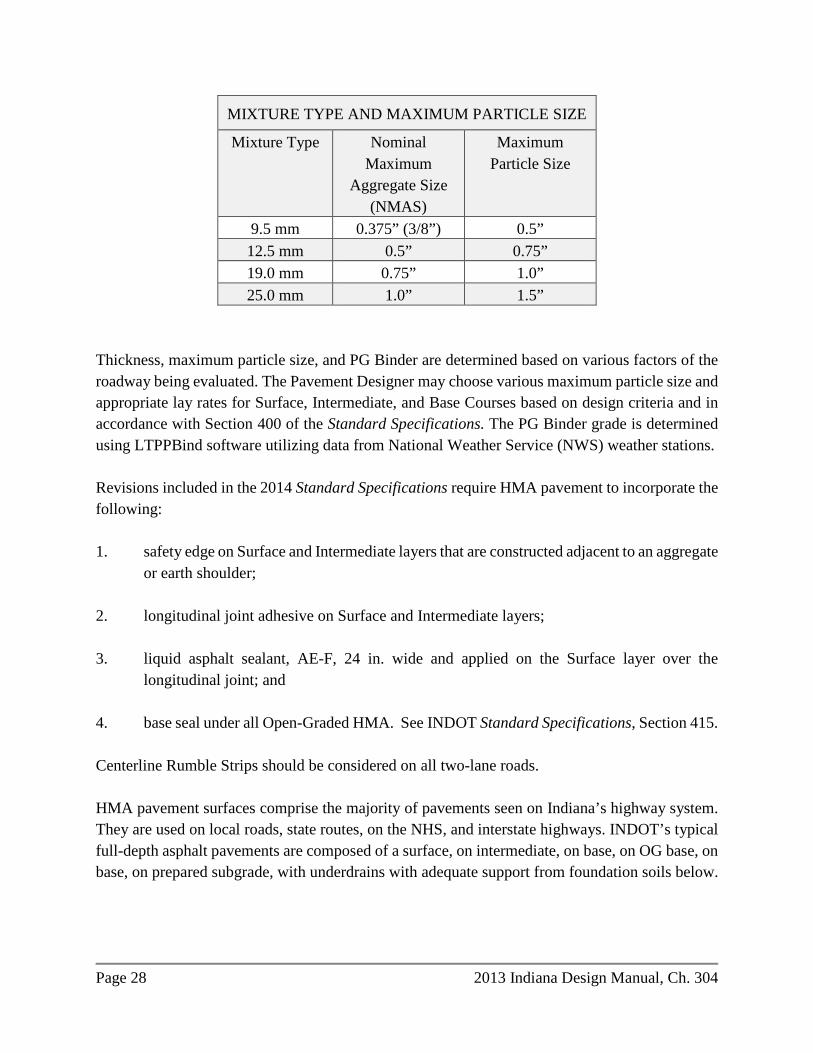
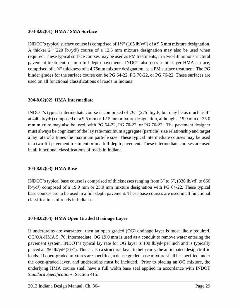
pavement if confined between two base layers or between an intermediate and base layer. Typical sections for HMA pavements are included in Section 304-21. Lay or layer thicknesses are determined by the Nominal Maximum Aggregate Size, (NMAS) used in each mixture designation. Reference the table below entitled, Mixture Type and Maximum Particle Size. A layer thickness is what a pavement design engineer designs for a certain mixture designation. A layer may have to be divided into two or more lifts to accomplish proper construction and compaction. So a pavement designer must consider both the layer thickness and whether it needs to be divided into multiple lifts, and can these lifts be constructed and compacted accordingly. Lay thicknesses play an important role in HMA construction quality control. Neither high lift thickness nor low lift thickness is desirable to achieve good compaction results. From a mechanistic point of view, the compaction pressure applied to the HMA layer is the highest at the top surface of the lift where the HMA materials directly contact the compacting roller. This compaction pressure decreases with depth, which means that if the lift thickness is too high, the required compaction pressure may not be applied to the materials at the bottom of the lift. On the other hand, since compaction is significantly affected by the lay down temperature and the temperature decreases more quickly with thin HMA lifts, good compaction result cannot be achieved either if the lift thickness is too low. In addition, there are many other factors that affect HMA compaction. Some of these factors are the nominal maximum aggregate size, aggregate gradation, and types of the asphalt binders. The Standard Specifications require that the finished thickness of any course shall be at least 2 times but not more than 4 times the maximum particle size as shown on the Design Mix Formula (DMF). This requirement applies during construction; however, the pavement designer should design the lay thickness according to the research findings from NCHRP – 531. NCHRP - 531 indicated that the HMA pavement density that can be obtained under normal rolling conditions is clearly related to the ratio of thickness/NMAS of the HMA. To achieve proper compaction, the thickness/NMAS ratio should be 4, or the thickness/Maximum Particle Size should be 3. The pavement designer should target lifts of 3 times the Maximum Particle Size and avoid designing to the minimum or maximum. Likewise the pavement design should specify the smaller aggregate size for intermediate and base mixtures where given the choice. While this will require more binder, this makes for a more desirable pavement structure: better density, better stability, and less permeability. If the design layer thickness of a specific layer exceeds 4 times the Maximum Particle Size, then that specific layer should be laid in two lifts, e.g., 770 lb./yd² of Base, 19.0 mm shall be laid in two lifts of 385 lb./yd² each lift.
Page 28 2013 Indiana Design Manual, Ch. 304
MIXTURE TYPE AND MAXIMUM PARTICLE SIZE
Mixture Type Nominal Maximum
Aggregate Size (NMAS)
Maximum Particle Size
9.5 mm 0.375” (3/8”) 0.5” 12.5 mm 0.5” 0.75” 19.0 mm 0.75” 1.0” 25.0 mm 1.0” 1.5”
Thickness, maximum particle size, and PG Binder are determined based on various factors of the roadway being evaluated. The Pavement Designer may choose various maximum particle size and appropriate lay rates for Surface, Intermediate, and Base Courses based on design criteria and in accordance with Section 400 of the Standard Specifications. The PG Binder grade is determined using LTPPBind software utilizing data from National Weather Service (NWS) weather stations. Revisions included in the 2014 Standard Specifications require HMA pavement to incorporate the following: 1. safety edge on Surface and Intermediate layers that are constructed adjacent to an aggregate
or earth shoulder; 2. longitudinal joint adhesive on Surface and Intermediate layers; 3. liquid asphalt sealant, AE-F, 24 in. wide and applied on the Surface layer over the
longitudinal joint; and 4. base seal under all Open-Graded HMA. See INDOT Standard Specifications, Section 415. Centerline Rumble Strips should be considered on all two-lane roads. HMA pavement surfaces comprise the majority of pavements seen on Indiana’s highway system. They are used on local roads, state routes, on the NHS, and interstate highways. INDOT’s typical full-depth asphalt pavements are composed of a surface, on intermediate, on base, on OG base, on base, on prepared subgrade, with underdrains with adequate support from foundation soils below.
2013 Indiana Design Manual, Ch. 304 Page 29
304-8.02(01) HMA / SMA Surface INDOT’s typical surface course is comprised of 1½” (165 lb/yd²) of a 9.5 mm mixture designation. A thicker 2” (220 lb./yd²) course of a 12.5 mm mixture designation may also be used when required. These typical surface courses may be used as PM treatments, in a two-lift minor structural pavement treatment, or in a full-depth pavement. INDOT also uses a thin-layer HMA surface, comprised of a ¾” thickness of a 4.75mm mixture designation, as a PM surface treatment. The PG binder grades for the surface course can be PG 64-22, PG 70-22, or PG 76-22. These surfaces are used on all functional classifications of roads in Indiana. 304-8.02(02) HMA Intermediate INDOT’s typical intermediate course is comprised of 2½” (275 lb/yd², but may be as much as 4” at 440 lb/yd²) composed of a 9.5 mm or 12.5 mm mixture designation, although a 19.0 mm or 25.0 mm mixture may also be used, with PG 64-22, PG 70-22, or PG 76-22. The pavement designer must always be cognizant of the lay rate/maximum aggregate (particle) size relationship and target a lay rate of 3 times the maximum particle size. These typical intermediate courses may be used in a two-lift pavement treatment or in a full-depth pavement. These intermediate courses are used in all functional classifications of roads in Indiana. 304-8.02(03) HMA Base INDOT’s typical base course is comprised of thicknesses ranging from 3” to 6”, (330 lb/yd² to 660 lb/yd²) composed of a 19.0 mm or 25.0 mm mixture designation with PG 64-22. These typical base courses are to be used in a full-depth pavement. These base courses are used in all functional classifications of roads in Indiana. 304-8.02(04) HMA Open Graded Drainage Layer If underdrains are warranted, then an open graded (OG) drainage layer is most likely required. QC/QA-HMA 5, 76, Intermediate, OG 19.0 mm is used as a conduit to remove water entering the pavement system. INDOT’s typical lay rate for OG layer is 100 lb/yd² per inch and is typically placed at 250 lb/yd² (2½”). This is also a structural layer to help carry the anticipated design traffic loads. If open-graded mixtures are specified, a dense graded base mixture shall be specified under the open-graded layer, and underdrains must be included. Prior to placing an OG mixture, the underlying HMA course shall have a full width base seal applied in accordance with INDOT Standard Specifications, Section 415.
Page 30 2013 Indiana Design Manual, Ch. 304
304-8.02(05) Compacted Aggregate Base HMA over compacted aggregate pavement will be designed as flexible pavement. See Figures 304-21F, 304-21G, 304-21M, and 304-21N for specific details. The project designer should use the appropriate mixture designations shown for QC/QA-HMA or HMA mixtures in accordance with Section 304-15.0. The compacted aggregate should be as designed within the limits shown in the 304-21 series of figures. The compacted aggregate base functions as a structural layer while economically increasing the pavement thickness to help protect the pavement from the effects of frost action. Compacted aggregate bases are used under aggregate, HMA, or PCC pavements. See INDOT Standard Specifications, Section 301, including any recurring special provisions for aggregate bases. A compacted aggregate is typically used on shoulders; see INDOT Standard Specifications, Section 303, for aggregate pavements or shoulders. 304-8.03 Portland Cement Concrete Pavement Portland cement concrete pavement (PCCP) consists of concrete materials on Subbase for PCCP, or on Dense Graded Subbase, on a treated subgrade. PCCP is composed of portland cement, pozzolanic materials (such as fly ash), coarse and fine aggregates, water, and chemical admixtures. Dowels are constructed at transverse planned joints to provide load transfer between adjacent panels, and tie bars are placed along longitudinal joints to provide lateral support, tying two lanes together. Safety edge shall be constructed where the pavement is constructed adjacent to earth or aggregate shoulder. PCCP is typically used on the Interstate system and the NHS, particularly where there are high volumes of traffic, especially trucks. PCCP is also used on state routes and in urban areas. INDOT has exclusively constructed Jointed Plain Concrete Pavements (JPCP) in the last three decades. Continuously Reinforced Concrete (CRC) Pavements were initially constructed on the Interstate system in Indiana in the 1960’s and1970’s. However, CRC Pavements in Indiana were constructed without drainable subbases and without underdrain systems and had inherent subgrade problems and began pumping and consequently “punch-outs” occurred. There are very few bare CRC Pavements remaining; most CRC pavements have been covered with HMA or PCCP. Use of CRC pavement can still be considered if traffic and economic considerations show it is the best alternative for a project. See Section 304-16.02 for CRC. See INDOT Standard Specifications, Section 500, including any recurring special provisions, for concrete pavement.
2013 Indiana Design Manual, Ch. 304 Page 31
Subbase for PCCP consists of two layers of aggregate placed under PCCP to prevent pumping of erodible subgrade material and to provide support for the pavement. The two layers are composed of a 3” OG aggregate, No. 8 on 6” dense graded compacted aggregate No. 53. A drainable subbase provides a conduit to remove water that enters the pavement system and should be used for pavement where underdrains are required. Dense Graded Subbase is used under PCCP where underdrains are not used. A dense graded subbase provides for a stable working platform together with support for the pavement without drainage layers. See INDOT Standard Specifications, Section 302, including any recurring special provisions, for subbase. 304-8.04 Composite Pavement A composite pavement consists of multiple pavement types, i.e., HMA over PCCP or PCCP over asphalt. A composite pavement should be designed in accordance with MEPDG using AASHTOWare Pavement ME software. The majority of INDOT pavements today are composite pavements. Special attention should be used when patching, widening, overlaying, or otherwise rehabilitating composite pavements. A pavement designer should match the existing pavement composition, if possible when patching and widening composite pavements. Additional testing is usually required to determine the strength parameters of a composite pavement. Cores are always required to define the composition of a composite pavement. 304-9.0 PAVEMENT DISTRESSES The strengths and limitations of each pavement system must be understood prior to designing a pavement. The type, extent, and severity of pavement distresses and their causes and recommended treatments should be well known. See Distress Identification Guide, LTPP, FHWA Publication Number: FHWA-RD-03-031, latest version, for additional information. Types of distresses related to aggregate pavement are as follows: 1. Dusting 2. Potholing 3. Rutting 4. Washboarding Types of distresses related to asphalt pavement are as follows: 1. Block Cracking 2. Bleeding
Page 32 2013 Indiana Design Manual, Ch. 304
3. Blowup – On Composite Pavement with Concrete below HMA 4. Edge Cracking 5. Fatigue Cracking 6. Frost Heave 7. Longitudinal Cracking 8. Longitudinal Joints Open 9. Potholes 10. Polishing 11. Raveling 12. Reflective Cracking 13. Rutting 14. Shoulder Drop-off 15. Shoving 16. Stripping 17. Thermal Cracking 18. Transverse Cracking – Top-Down or Bottom-Up 19. Weathering. Types of distresses associated with concrete pavement are as follows: 1. Alkali-Silica Reactivity (ASR) 2. Blowup 3. Corner Break 4. Durability Cracking ("D" Cracking) 5. Faulting 6. Joint Failure (including Longitudinal Joint related to De-Icing Chemicals) 7. Longitudinal Cracking 8. PCCP Joint-Seal Failure 9. Polishing 10. Poor Rideability 11. Pop-out 12. Pumping 13. Punch-out 14. Transverse Cracking 15. Scaling 16. Spalling 17. Structural Failure
2013 Indiana Design Manual, Ch. 304 Page 33
304-10.0 PAVEMENT MILLING An asphalt or concrete pavement may be milled to remove distressed layers of material, make crown corrections, maintain curb height or vertical clearance, scarify existing surface, surface profiling, removal of asphalt overlay, or to provide a pavement transition. See INDOT Standard Specifications, Section 306, including any recurring special provisions, for milling. The types of pavement milling and their applications are as follows: 1. Asphalt or PCCP Scarification Milling. Scarification milling is used to roughen the surface
or remove excessive crack sealant prior to placing an HMA overlay. 2. Asphalt or PCCP Profile Milling. Profile milling is used to correct a cross-slope (crown)
deficiency. 3. Approach Milling. Approach milling is used to provide a smooth connection between an
overlay and driveways, commercial or public-road approach, and mailbox approaches. 4. Asphalt or PCCP Milling. Asphalt or PCCP milling is used to remove distresses near the
surface of the pavement or prior to placing an HMA inlay. 5. Asphalt Overlay Removal. Asphalt overlay removal is used to remove asphalt materials
down to a concrete or brick base. 6. Transition Milling. Transition milling is used to provide a transition to an adjoining
section. 304-10.01 Asphalt or PCCP Scarification Milling Asphalt or PCCP scarification milling is used to provide a roughened texture to an existing surface. Asphalt or PCCP scarification milling will remove crack sealant to prevent slippage of the overlay materials or roughen the existing surface that has polished due to traffic. Milling operations to correct pavement conditions that require deeper milling should be in accordance with Section 304-10.04. Asphalt or PCCP scarification milling is generally used to prepare an existing pavement for a single-course HMA overlay. Asphalt or PCCP scarification milling is used to prepare an existing pavement for a functional overlay if the existing pavement has excessive crack sealant or requires minor profile corrections.
Page 34 2013 Indiana Design Manual, Ch. 304
304-10.02 Asphalt or PCCP Profile Milling Asphalt or PCCP profile milling is used to correct minor profile or cross-slope (crown) deficiencies. 304-10.03 Approach Milling The application of approach milling is used to provide a connection between an overlay and driveways, commercial or public-road approach, and mailbox approaches. The transition slope and notch depth in the existing asphalt or concrete pavement will be in accordance with the INDOT Standard Drawings. Approach milling is not to be performed at driveways unless it is required to meet a paved surface that continues beyond the construction limit. If the driveway is other than HMA or PCC beyond the construction limits, the approach milling is not required. 304-10.04 Asphalt or PCCP Milling Asphalt or PCCP milling is intended to remove material from an existing pavement to a specified average depth by milling the surface and creating a uniform profile. An average depth of milling should be specified depending on the condition of the pavement or project requirements. Asphalt and PCCP milling maybe used in the following cases: 1. prior to placing an HMA or PCCP inlay; 2. to correct substandard cross slope or crown condition; 3. profile correction; or 4. to maintain vertical clearance or curb height. In addition to the cases listed above, Asphalt milling may be used for the removal of stripped or distressed asphalt. The average milling depth specified will be sufficient to accommodate the HMA inlay, or the removal of distressed materials, and to achieve the desired cross slope. For a variable milling depth to correct a cross-slope deficiency, the limits and associated milling depths must be shown on the typical cross sections in accordance with the series of Figures 304-21.
2013 Indiana Design Manual, Ch. 304 Page 35
304-10.05 Asphalt Overlay Removal Asphalt overlay removal consists of milling to remove an entire asphalt overlay from a concrete or brick base. The designer will designate the approximate existing asphalt thickness on the typical cross sections. The designer should be aware that milling can dislodge or loosen bricks and result in construction challenges. To avoid construction issues associated with bricks, it is recommended to allow a sufficient amount, at least 2 in. or more, of existing asphalt pavement to remain in-place to keep the bricks stable. 304-10.06 Transition Milling Transition milling is used to provide a connection between an HMA overlay and an adjoining pavement, paving exception, or at the beginning and end of the paving project. The transition slope and notch depth in the existing asphalt or concrete pavement will be in accordance with the INDOT Standard Drawings. 304-11.0 PAVEMENT PATCHING The project manager and the pavement designer to determine and overcome critical project challenges such as maintenance of traffic (MOT), pavement patching, temporary pavements, drainage (underdrains), etc. The pavement designer must be aware of the requirements and follow the Lane Closure Policy of the Department, or request an exception with adequate justification. The Pavement Designer is responsible for specifying the composition, depth, and location of various patch types. The Pavement Designer shall produce a Patching Table to assist in the proper design and construction of the patches on the project. A Patching Table including start station locations and end station locations of the patches, lane (travel, passing, mainline, shoulder, approach, etc.), direction (NB, SB, etc.), length (ft), width (ft), and area (yd²) shall be shown on the Plans. Separate tables shall be produced for partial depth patches and full depth patches. See Typical Patch Sections Figures 304-21CC, 304-21DD, 304-21EE, and 304-21FF. 304-11.01 PCCP Patching, Full Depth
Page 36 2013 Indiana Design Manual, Ch. 304
The Pavement Designer must coordinate with the roadway designer to determine MOT with consideration of how long a lane can be closed during the patching operation. See Chapter 82 for work zone traffic control considerations. All PCCP patches shall be doweled to the existing remaining concrete pavement. A 6-ft minimum and 15-ft maximum spacing shall be between two D-1 joints. If a 20-ft panel is replaced, a D-1 joint shall be installed at 10 ft. Whenever possible, match the transverse joints with adjacent lanes. Patches less than one panel in length do not need to be tied to the existing concrete pavement. For a 20-ft original concrete joint spacing, the slab movement will be about 1/12 ft. So for every 60 ft of patching length (intermittent or continuous patching), ¼-in foam should be placed. PCCP Patching using 502 mixture can be opened to traffic as follows: 1. Construction vehicles and equipment after 10 days or when test beams indicate a modulus
of rupture (flexural strength) of at least 550 psi. 2. Non-construction traffic after 14 days or when test beams indicate a modulus of rupture
(flexural strength) of at least 550 psi. All cracks and joints must be sealed. The 550 psi strength can typically be reached in 2 days (48 hours), when using 502.04(b) High Early Strength (HES) concrete. This allows for a 12-hour curing time. It is recommended to use 502 HES concrete on long patches (> 16’). The designer should only use 506 PCCP Patching mix when a lane must be open during the daylight hours and the contractor only has from 6:00 p.m. to 6:00 a.m. for night construction. 506 mixes should only be used on maximum 16-ft long patches. See INDOT Standard Specifications, 506.11 Opening to Traffic. The integrity of the underdrains should be maintained in the patching process. The designer should incorporate the underdrain details in the design; including sequencing of the patching process in conjunction with underdrain installation. Patching should not disturb or block/clog underdrain. A minimum of 6 years of service life should be expected for a patching project. For a PCCP structural pavement treatment project if the patching is over 8%, an LCCA should be completed to compare a PCCP overlay or slab-reduction technique, e.g., PCCP rubblization with an HMA overlay. Also if patching is at or above 30%, a reconstruction project should be considered as an alternate treatment based on economic analysis. Use inverted-T patches where dowels cannot be drilled into the old slab. Dowels cannot be secured into an old PCCP concrete slab if it has been cracked and seated, rubblized, or cores indicate it has significant deterioration. See Figures 304-21EE and 304-21FF for typical sections.

2013 Indiana Design Manual, Ch. 304 Page 37
Page 38 2013 Indiana Design Manual, Ch. 304
304-11.02 HMA Patching HMA partial-depth patch may be used where the deterioration is only in the upper one or two layers of existing HMA. A partial depth patch has been historically referred to as “drop the drum”, since the removal process is accomplished by the milling machine dropping the milling drum deeper in the location of the patch, typically to a 3” to 6” depth. Then the hole is filled with new HMA (HMA Patching, Type ), as this process is usually included in an overlay project. After the final milling is accomplished the HMA surface is applied. Longitudinal patching is usually required in a widened area, where the existing asphalt surface has an open longitudinal crack or joint at the mainline/widened interface. A longitudinal patch should be placed by milling or otherwise removing the upper one or two layers of HMA and installing new HMA. Depth and width of the patch is critical to assuring that the new HMA can be installed with proper density. Reference INDOT Standard Specifications, Section 304. Patch width is critical in order to obtain proper compaction. A vibratory roller is typically 8’ wide. There are smaller non-vibratory rollers as small as 4’ wide, and even smaller hand-controlled “jumping jack” compactors. Only the vibratory roller can definitively compact the HMA to the desired density. The Pavement Designer should avoid designing small patches having a width less than 2’. The integrity of the underdrains should be maintained in the patching process. The designer should incorporate the underdrain details in the design; including sequencing of the patching process in conjunction with underdrain installation. Patching should not disturb or block/clog underdrain. The pay item is “HMA Patching, Type____,” per INDOT Standard Specifications, Section 304. 304-11.03 Composite Patching Composite patches should always match existing pavement composition and depths where practical. The Pavement Designer will determine the most appropriate patch composition and depth. Patch width is very critical for achieving the proper compaction. The integrity of the underdrains should be maintained in the patching process. The designer should incorporate the underdrain details in the design; including sequencing of the patching process in conjunction with underdrain installation. Patching should not disturb or block/clog underdrain. See Figure 304-21EE for typical section. 304-12.0 PAVEMENT WIDENING
2013 Indiana Design Manual, Ch. 304 Page 39
Where pavements are being widened in an overlay project the widening is brought up to the elevation of the existing pavement and an overlay is constructed over the widened area and the existing pavement simultaneously for continuity. The depth of the widened area must be at least that of the adjacent pavement so that the subgrade is not stepped. In excessively thick sections compacted aggregate may be substituted for a portion of the HMA. Prior to overlay the area of the existing pavement and new widening are scarification/profile milled to make a smooth plane for the overlay. All costs for widening pavements 5 ft or less are included in INDOT Standard Specifications Section 304 Widening with HMA or Section 305 Widening with PCCP Base. All costs for widening pavements 5 ft or more are determined based on the individual components of the work. 304-12.01 Widening with HMA An existing pavement may be widened to 5 ft or less on each side if widening with HMA. However, the minimum width of widening with HMA specified is 2 ft for constructability purposes. This minimum width of widening may result in extra lane width or may require removal of existing pavement to satisfy the 2-ft minimum-width requirement. The longitudinal joint of the widened pavement should not be located in the wheel path of the driving lane. The pay-item designation for this work will be in accordance with Section 304 of INDOT Standard Specifications, Widening with HMA, of the type required, regardless of the quantity involved. If specific project widening requirements exceed 5 ft, the widened pavement area will not be specified as HMA widening, but will be identified as HMA pavement. The pay items specified will be QC/QA-HMA in accordance with Section 401, and the excavation and subgrade treatment will be as described in the INDOT Standard Specifications, Section 207. If the existing pavement has underdrains and OG layer, the widening design shall perpetuate the underdrain system. 304-12.02 Widening with PCC Base If widening of the pavement is needed and the existing subbase is open graded, the widened PCC base will utilize Subbase for PCCP. If the existing subbase is dense graded, the widened PCC base will utilize Dense Graded Subbase. The width of PCC base widening is limited to pavement widening of less than or equal to 5 ft. An existing pavement may be widened up to 5 ft on both sides with PCC base. The pay item designation of this work will be Widening with PCC Base, ___ in., in accordance with the INDOT Standard Specifications, Section 305.
Page 40 2013 Indiana Design Manual, Ch. 304
304-12.03 Widening for Composite Pavements Widening of asphalt over PCC (composite) pavement will be designed to match the existing pavement. If widening of the pavement is needed and the existing subbase is open graded, the widened PCC base will utilize Subbase for PCCP. If the existing subbase is dense graded, the widened PCC base will utilize Dense Graded Subbase. See INDOT Standard Specifications, Section 302. It may not be cost effective or practical to widen a composite pavement by 2’ to 5’ for one or two miles. Also the old concrete may not be in suitable condition to install tie bars. There must be good engineering analysis to determine the cost effectiveness or practicality of the widening. In situations such as this, widening with HMA should be considered. 304-13.0 PAVEMENT TESTING INDOT does pavement testing to determine strength, cause of failures, and basic forensics. These tests include, but are not limited to: 1. Falling Weight Deflectometer (FWD) 2. Ground Penetrating Radar (GPR) 3. Coring 4. Friction 304-13.01 Falling-Weight-Deflectometer (FWD) Testing The pavement designer should evaluate the need for FWD testing pertaining to concrete, asphalt, or composite pavement. The FWD data is used, but not limited to, evaluating the structural adequacy of an existing pavement section, evaluating pavement shoulder adequacy for temporary traffic, or providing an estimated quantity of underseal to be included in the plans for an existing PCCP over dense graded subbase. The INDOT Deflection Testing Request Form is available on the Department’s website at www.indotresearch.org. FWD testing must be requested at no later than the 30% stage of plan development (Stage 1). FWD testing cannot be performed during the winter months, typically between late October and late April. This must be taken into account when requesting the testing. The district should coordinate traffic-control activities for the FWD testing.
2013 Indiana Design Manual, Ch. 304 Page 41
304-13.02 Ground Penetrating Radar (GPR) Testing The pavement designer should evaluate the need for GPR testing pertaining to concrete, asphalt, or composite pavement. The GPR data is used to detect anomalies and moisture under the pavement structure and also to detect the drainage system and reinforcing steel locations. GPR works best where moisture is present. The INDOT GPR Request Form is available on the Department’s website at www.indotresearch.org. 304-13.03 Pavement Coring The pavement designer should evaluate the need for pavement coring. Cores are required for all pavement rehabilitation projects and the information should be requested in advance of the date it is required for project selection. Cores are used to verify the thickness, composition, structural condition, and forensic evaluation of the existing pavement. Forensic cores may need to be tested by INDOT Materials Management for material quality, and these tests are to be arranged by the district or Central Office Pavement Engineer. Cores for history or thickness verification should be taken in locations of sound pavement. Cores must be obtained during non-freezing temperature periods due to equipment and safety concerns. The District should coordinate traffic-control activities for the coring, as much as possible. For an LPA project, the LPA shall be responsible for coring and traffic control. A Core Report should be produced that discusses the findings of the cores and core photographs should be included. Cores should be located as follows: 1. at least every ½ mile in each lane; 2. at select joints with distresses; 3. in existing widened areas where it is obvious there is a different pavement structure than
the mainline; 4. at cracks to determine top-down or bottom-up cracking; and 5. at predominant distress locations.
Page 42 2013 Indiana Design Manual, Ch. 304
304-13.04 Pavement Friction Wet weather pavement friction is one of the most important components providing safety on the nation’s highways. Pavement friction is provided through two primary characteristics of the pavement surface; microtexture and macrotexture.
“The microtexture is the fine scale texture of the aggregate particles themselves, usually defined as less than 0.5 mm. Microtexture determines the friction of the pavement surface at low speeds. Macrotexture is large scale texture, on the order of 0.5 to 50 mm, provided between the aggregate particles. Macrotexture provides channels through which surface water can flow, providing surface drainage and improving the contact between vehicle tires and the pavement. This texture helps to decrease the chances for a vehicle to hydroplane in wet weather. In general, as the speed of the vehicle increases, the friction decreases, but the rate at which it decreases depends on the pavement macrotexture and how quickly water can be forced out of the tire-pavement interface. Higher macrotexture allows for more rapid drainage of the water and therefore a higher friction value.” (McDaniel, R. S., Investigating the Feasibility of Integrating Pavement Friction and Texture Depth Data in Modeling for INDOT PMS, JTRP SPR-2936, October 2012, p.2.)
The INDOT Research Division annually conducts approximately 6,700 lane-miles of friction testing using ASTM E274 Standard Test Method for Skid Resistance of Paved Surfaces Using a Full-Scale Tire, (towed friction trailer). The towed friction trailer uses smooth tires and applies water just in front of the tires as the test progresses at a constant speed, 30, 40, and 50 mph. When the friction number (FN) is below a so-called friction flag value, the District is informed and the site is visited to determine if remediation is needed. Friction testing may be requested of the INDOT Research Division if the district Pavement Engineer or district Maintenance personnel deem it necessary to help evaluate the pavement for proper treatment. See www.indotresearch.org for more information. 304-14.0 MECHANISTIC EMPERICAL PAVEMENT DESIGN GUIDE The Mechanistic Emperical Pavement Design Guide (MEPDG), AASHTO's pavement design guide, shall be used for the design of each pavement structure. The design process is based on the predictive performance of a pavement section to be designed to predefined parameters identified as failing. The pavement design itself is an iterative process where the pavement designer selects a cross section for the pavement based on economic benefits, performance, maintenance, and constructability. The objective of pavement design using the MEPDG process is to make iterative
2013 Indiana Design Manual, Ch. 304 Page 43
inputs to the input parameters identified as important and critical, process the inputs to determine the pavement performance prediction, and compare the pavement-performance prediction with a preset performance requirement. Therefore, more than one design may satisfy the preset performance requirement. The final design must satisfy the performance-indicator criteria (threshold value) and design reliability level for the project and be economically justified. This section discusses the typical factors and inputs to be used with the MEPDG using AASHTOWare Pavement ME Design software formerly known as DARWinME. The organization of the factors and inputs is based on the various sections of the software. 304-14.01 MEPDG General Inputs Using AASHTOWare Pavement ME Design software 1. General Information.
a. Design Type. Select from one of three options; New Pavement, Overlay and Restoration. If performing alternative analyses, save the project with a different name before changing it to a different design type.
b. Pavement Type. When analyzing a new pavement, choices are Flexible Pavement,
Jointed Plain Concrete Pavement (JPCP), and Continuously Reinforced Concrete Pavement (CRCP). When analyzing an overlay, choices are Asphalt Concrete (AC) over AC, AC over JPCP, AC over CRCP, various bonded concrete overlays, and unbounded concrete overlays over AC, JPCP and CRCP. The Restoration design type is for JPCP restoration analysis. The software is only capable of analyzing for one existing pavement type, so when looking at an overlay of an existing HMA over concrete pavement, there are two ways to set up the analysis as either AC over AC with concrete being seen as crushed stone with the resilient modulus shown from the FWD results, or AC over the concrete pavement representing the existing AC as new AC with the properties of the existing pavement.
c. Design Life, Years. See Figure 304-14A, Pavement Design Life, for pavement
performance periods. The design life can also be set to a higher value that insures failure to determine the actual mode and time of failure.
d. Base Construction/Existing Construction. This is the month and year of the
scheduled construction of the granular base or prepared subgrade for new pavements or the existing pavement construction year for overlays or restorations. The base construction input is only for a new HMA pavement and is an important
Page 44 2013 Indiana Design Manual, Ch. 304
parameter used to calculate the predictive performance of the pavement. For an INDOT project, it is to be assumed that the base or subgrade will be constructed in May. The existing construction month and year would be based upon the initial construction date for concrete pavements or the date for the construction of the layer that is at the bottom of the proposed mill for an HMA pavement.
e. Pavement Construction Month. This is the month and year of the scheduled
placement of the HMA or PCCP. This input is an important parameter used to calculate the predictive performance of the pavement. For an INDOT project, it is to be assumed that the pavement will be constructed in July.
f. Traffic Open Month: This is the month and year of the scheduled opening to traffic
upon completion of the project. This input is an important parameter used to calculate the predictive performance of the pavement. For an INDOT project, it is to be assumed that the pavement will be opened to traffic in September. Traffic Open Month must be more than one month after Pavement Construction Month.
2. Analysis Parameter. The inputs in this section are important and sensitive to the analysis
and the final design of the project.
a. Initial IRI (in./mi). This is the predictive International Roughness Index for newly-constructed pavement. A typical value is 70 in./mi for both HMA and PCCP surfaces.
b. Performance Criteria for Pavement Design. These are the performance criteria used
for acceptability of the iterative trials. These are the most important inputs that the trial design must achieve or exceed. Performance criteria for asphalt pavement is shown in Figure 304-14B. Performance criteria for concrete pavement is shown in Figure 304-14C. The failure modes of top-down cracking and total deformation are not to be considered for INDOT pavement design and should be ignored in the analysis.
3. Traffic Inputs. Determine Traffic Group A, B, C, or D from Item 4.a. below. Prior to
importing the AADTT and other inputs such as the number of lanes in the design direction, import the site-specific traffic group data from the traffic input files. See Item 4 for more information related to traffic. Check to make sure the value from the import is correct for the specific project.
2013 Indiana Design Manual, Ch. 304 Page 45
4. INDOT Default Traffic-Distribution Input Files. These are available to an INDOT designer within the Citrix drive location for the software through a shortcut under the user name of each designer. The information is also available to a pavement designer outside of INDOT on the Department’s website. The user of the software will be able to import the Traffic Volume Adjustment, Axle Load Distribution Factor, and the General Traffic Inputs.
a. Initial Two-Way AADTT. This value is the Average Annual Daily Truck Traffic
(AADTT) after the roadway is opened to traffic or the rehabilitation has been completed. It represents both directions and all lanes. For ramps and one way roads double the AADTT input. Traffic is divided into four Truck Weight Road Groups (TWRG), based on the AADTT, as follows:
1) Traffic Group A, AADTT ≤ 3,000 2) Traffic Group B, 3,000 < AADTT ≤ 6,000 3) Traffic Group C, 6,000 < AADTT ≤ 20,000 AADTT 4) Traffic Group D, AADTT > 20,000 The TWRG traffic import should be made before any actual traffic information
is entered because it will be overwritten at the time of the import.
b. Number of Lanes in Design Direction. This is the number of traveled main lanes in the design direction, not including the acceleration, deceleration, or turn lanes.
Example: 4-lane road with 2 lanes east bound and 2 lanes west bound. The input
is 2. Check to make sure the value from the import is correct for the specific project.
c. Percent of Trucks in the Design Direction. This value represents the percentage of trucks in the design direction relative to all trucks using the roadway in both directions. The recommended values are as follows:
1) 2-Lane Road, 52% 2) 4-Lane Road, 55% 3) 6-Lane Road, 55% 4) 8-Lane Road, 57% 5) 10-Lane Road, 55% 6) 12-Lane Road, 54% Check to make sure the value from the import is correct for the specific project.
Page 46 2013 Indiana Design Manual, Ch. 304
d. Percent of Trucks in the Design Lane. This value represents the percent of trucks
of FHWA Class 4 and above in the design lane in the design direction relative to all trucks using the roadway in both directions.
1) 2-Lane Road, 100% 2) 4-Lane Road, 90% 3) 6-Lane Road, 60% 4) 8-Lane Road, 45% 5) 10-Lane Road, 40% 6) 12-Lane Road, 40% 7) 1-Lane Ramp or Street, 100% 8) Multi-Lane Ramp, 90% 9) Multi-Lane One-Way Street, 90% Check to make sure the value from the import is correct for the specific project.
e. Operational Speed. This value represents the posted truck speed limit. The posted
speed limit should be used for all traffic groups.
f. Growth Rate. This value represents the growth of truck traffic during the pavement life. Assuming that the growth rate is uniform over time, the rate of increase remains the same throughout the design period.
The recommended growth method is linear growth. The project-specific Traffic Growth Factor should be used. If the growth rate from the import does not match the given growth rate for the project, the corrected growth rate must be entered for each class of truck.
g. Design Lane Width. This value represents the width of the through lane. The input
entry is in the Lateral Wander section of the traffic inputs. The default lane width is set to 12 ft. If the lane width for a specific project is less than 12 ft, enter the correct width. If the lane width is more than 12 ft, e.g., on a single lane ramp, then leave this entry as 12 ft.
h. Mean Wheel Location. This value represents the distance for the outer edge of the
wheel to the edge travel lane. The change in design lane width requires changes to the mean wheel location. If the design lane width is 10 ft then the mean wheel location would be 6 in. If the design lane width is 11 ft, then the mean wheel
2013 Indiana Design Manual, Ch. 304 Page 47
location would be 12 in. The default value for the mean wheel location in a 12-ft lane is 18 in.
i. Axle Distributions. Single, tandem, tridem and quad-axle distributions are available
for each TRWG and must be imported. 5. Climate. The climate inputs in the AASHTOWare Pavement ME Design software are
based on the project location. A climatic data file must be generated for each pavement design project . There are 7 specific climate inputs from 7 weather stations in Indiana, and most are in major cities. There are also weather stations in surrounding states that might be closer to a project. Virtual weather stations can be created. When the latitude and longitude of the project are entered, the software will present the closest weather stations. If a weather station has missing data, this can be corrected. Specific climate data has to be imported from a file.
6. Depth of Water Table. Use the water table depth as shown in the soil boring logs,
appropriately adjusted for soil types whose capillary action may raise the water table and climactic conditions. An example of climactic conditions would be if soil boring was taken during a drought which would not accurately represent the typical water table.
304-14.02 Flexible Pavement Layer Design A flexible pavement system consists of HMA, i.e., Surface, Intermediate, or Base, on an un-stabilized base layer or prepared subgrade. A final pavement structure design in the AASHTOWare Pavement ME Design software should include all of the layers shown in the series of Figures 304-21 typical pavement sections. Iterations should be conducted to minimize the HMA thickness while satisfying the pavement performance prediction for the design life. Optimal design and then one failure iteration must be submitted for review for each design. Each flexible pavement structure design using the software should be performed using the specific imports for the District that the project is within, the PG grade and the mixture type being used on each layer which is available to an INDOT designer within the Citrix drive location for the software with a shortcut to it under the user name of each designer. The information is also available to a pavement designer outside of INDOT on the Department’s website. 1. Structure.
a. Surface Shortwave Absorptivity. Use the software default value of 0.85.
Page 48 2013 Indiana Design Manual, Ch. 304
b. Layers. The layer inputs should be based on the INDOT Standard Specifications and Figures 304-21B, 304-21E, 304-21F, and 304-21G. A maximum of 6 input layers is supported. The maximum number of input layers that can be asphalt layers is 3. If the trial design includes a drainage layer, the bottom Base layer and drainage layer should be input as one dense graded Base layer, or if there is a Base layer on top and bottom of drainage layer, combine all three as one dense graded Base layer. The layer thicknesses should be in accordance with Figures 304-21A, 304-21C, 304-21D, and 304-21H.
1) Type, Material, and Thickness. These are determined based on the INDOT
Standard Specifications and Figures 304-21B, 304-21E, 304-21F, and 304-21G for the trial design.
2) In HMA pavement with OG layer, the bottom most HMA layer (between
OG and subgrade treatment) must be 3 in. thick. 3) The thickness of any HMA layer should not be at the minimum or maximum
lay rate for that material. The designer should target the total thickness of each layer in increments of 2 to 4 times the maximum particle size, preferably 3 times (4 times the nominal maximum aggregate size).
4) If the pavement design differs from typical sections shown in this chapter,
approval is required from the Pavement Engineering Manager. Include a sketch or modified drawing with the pavement design and justification for the change.
5) Bedrock. This can be ignored where the depth to it is greater than 20 ft.
6) Filter Fabrics. INDOT does not consider filter fabric to be a drainage layer.
For drainage purposes in the pavement structure, these should be ignored in the software design.
2. Material Properties. The Division of Pavement will maintain input files associated with
material properties. The input files will be available to an INDOT designer within the Citrix drive location for software with a shortcut to it under the user name of each designer. The information is also available to a pavement designer outside of INDOT on the Department’s website. The user of the software will be able to import the following from each file:
2013 Indiana Design Manual, Ch. 304 Page 49
a. dynamic modulus;
b. SuperPave Asphalt Binder Test data; and
c. asphalt general inputs. For 25.0 mm, 19.0 mm, 12.5 mm, 9.5 mm NMAS, or SMA 9.5 mm NMAS, values are provided in Figure 304-14D.
3. Thermal Cracking. For aggregate coefficient of thermal contraction, the range is from
4×10⁻⁶ to 8×10⁻⁶. Typically the value for limestone is 6.05×10⁻⁶. 304-14.03 Rigid Pavement Layer Design A rigid pavement system consists of portland cement concrete pavement on granular subbase on prepared subgrade. A final pavement structure design using the AASHTOWare Pavement ME Design software should include all the layers described in the typical sections shown in the series of Figures 304-21. Iterations should be conducted to minimize the structural thicknesses while satisfying the pavement performance prediction for the design life. Optimal design and then one failure iteration must be submitted for review for each design. If the optimization functionality in the software is used then a screenshot of the optimization results must be submitted with the optimized result. The optimization option only optimizes the PCCP thickness, so separate optimized designs should be created for varying joint spacing or dowel bar sizes. A new rigid-pavement trial should be started by first creating a template identifying all subgrade and pavement layers. 1. Design Features. The design feature inputs in the software should be based on the INDOT
Standard Specifications and Standard Drawings.
a. Surface Short-Wave Absorptivity, which is the concrete surface absorptivity value from sunlight. The typical value is 0.85.
b. Joint Spacing. This is the parameter in the design that determines the pavement
performance predictions as a requirement for the design. A typical range for the joint spacing is 15 to 18 ft. The most economical design has the longest joint spacing that satisfies the performance criteria. Ramps pose a unique challenge due to the potential for shorter joint spacing than slab width.
c. Sealant Type. Use the most predominant transverse sealant type, which is silicone
sealant for the transverse joints.
Page 50 2013 Indiana Design Manual, Ch. 304
d. Random Joint Spacing. This technique is no longer used.
e. Doweled Transverse Joint. This option should always be selected, except for thin
PCCP overlays less than 7”.
f. Dowel Diameter. These should be as specified by the designer. It is not recommended to use 1½” dowel diameter for PCCP less than or equal to 9” thick. All other combinations may be tried. The dowel diameter is limited to 1”, 1 ¼”, and 1 ½”.
g. Dowel Bar Spacing. Dowel bar spacing must be 12in. See Standard Drawings. h. Widened Slab. This option should be used if the pavement slab is wider than the
travel lane width, such as 14 ft and striped at a 12-ft width. This is typically used on divided highways without tied shoulders. For monolithically poured PCC pavement with concrete shoulder, the maximum slab width between longitudinal joint and the pavement edge or between two longitudinal joints should not exceed 14 ft. The slab width should be input into the software.
i. Tied PCC Shoulder or Curb. This is a project-specific input. For a curb with a
minimum 2-ft tie width, analyze in the software as “tied shoulder” if the curb is tied to the adjacent concrete pavement.
j. Long Term LTE (Load Transfer Efficiency). This should be 50% to 70% for a
sawed longitudinal joint with tie bar, 30% to 50% for a longitudinal construction joint with tie bar, or 0% for no tie bar. Use 60% as the typical value. For curb LTE use 50%.
k. PCC-Base Interface. Unless specified otherwise, the interface is full-friction
contact.
l. Erodebility Index. The value for a drainable No. 8 granular base is Very Erosion Resistant (2). The value for a No. 53 granular base is Erosion Resistant (3). The value for cement or asphalt stabilized base is Extremely Resistant (1).
m. Loss of Full Friction. Use 600 as the typical value (50-year life cycle times 12
months per year).
2013 Indiana Design Manual, Ch. 304 Page 51
2. PCC Material Properties. This section requires inputs for the thickness, thermal and mix properties of concrete.
a. Layer Thickness. This is the thickness of the concrete layer for trial design. The
pavement designer should select a trial design thickness based on experience from past projects. The minimum thickness shall be 8”. The selected trial design thickness should be in 0.5-in. increments. If pavement design differs from the typical sections shown in this chapter, approval is required from the Pavement Engineering Manager. Include a sketch or modified drawing with the pavement design and justification for the change. If optimization is used the range of analysis must also be presented. A screen shot of the optimization panel works as sufficient documentation.
b. Unit Weight. This is the dry unit weight of concrete based on AASHTO T 121. A
typical value is 145 lb/ft3.
c. Poisson Ratio. This is based on samples tested using AASHTO C 469. A typical value is 0.20.
d. Coefficient of Thermal Expansion (CTE). This is the coefficient based on samples
tested using AASHTO TP 60 (for AASHTOWare Pavement ME Design software). A typical range of Indiana CTE for the concrete mix varies from 4.7 x 10⁻⁶ to 6.1 x 10⁻⁶. A typical value for concrete mix is 5.4 x 10⁻⁶.
e. Thermal Conductivity. This is for concrete samples tested using ASTM E 1952. A
typical value is 1.25 BTU/h-ft-°F.
f. Heat Capacity. This is for concrete samples tested using ASTM D 2766. A typical value is 0.28 BTU/lb.-°F.
g. Cement Type. Select the appropriate cement type that is expected to be used in the
project. A recommended selection is Type I cement.
h. Cementitious Material Content. This value is from a typical mix design in accordance with the INDOT Standard Specifications. A typical value of Portland cement content is 400 lb/yd3, the minimum value per Standard Specifications. The minimum total cementitious is typically 510 lb/yd3 which includes supplemental cementitious materials such as fly ash.
Page 52 2013 Indiana Design Manual, Ch. 304
i. Water/Cement Ratio. This value is from a typical mix design from a previous concrete pavement project in accordance with the INDOT Standard Specifications. A typical value is 0.42 including supplemental cementitious materials such as fly ash.
j. Aggregate Type. Select the type of aggregate to be potentially used in the project
limits. Limestone is the most common type of aggregate.
k. PCC Zero-Stress Temperature. This value depends on the Mean Monthly Temperature and Cement content to determine the temperature of PCC zero stress during concrete hardening. The software provides a calculator option to calculate the typical temperature which should be set to True.
l. Ultimate Shrinkage at 40% Relative Humidity. This value represents the ultimate
shrinkage of a concrete sample in 40% relative humidity. The typical value is 483 microstrain.
m. Reversible Shrinkage. This value represents the reversible shrinkage of a concrete
sample as a percentage of the ultimate shrinkage. The typical value is 50%.
n. Time to Develop 50% of Ultimate Shrinkage. This value represents the time to develop 50% of the ultimate shrinkage. The typical value is 35 days.
o. Curing Method. This option depends on the curing method during construction of
the concrete pavement. The typical option is Curing Compound.
p. PCC Strength Properties. This section requires input based on the hierarchical inputs from Level 3 (lowest) to Level 1 (highest). The strength input for Level 3 is Modulus of Rupture. The value for 28-day Modulus of Rupture is 700 psi. The box should not be checked because the software calculates the elastic modulus internally.
304-14.04 Non-Stabilized Base Pavement Layer Design 1. Non-Stabilized – Drainage Layer. The purpose of this pavement layer is to move water
from underneath the pavement surface and to provide a platform on which to construct the subsequent PCCP. The typical material for this layer is coarse aggregate No. 8.
2013 Indiana Design Manual, Ch. 304 Page 53
a. Non-Stabilized Material. This input is related to the type of granular material to be used in the drainage layer. The typical option is crushed stone, although other materials also can be utilized based on geographical area and availability.
b. Coefficient of Lateral Pressure, Ko. This is for a representative sample of crushed
stone. The typical value is 0.5. c. Thickness. This is the thickness of the drainable granular layer only. The typical
value is 3 in.
d. Poisson ratio. This is for a representative sample of crushed stone. The typical value is 0.35.
e. Resilient Modulus.
1) Input Level. This option requires input based on the hierarchical inputs
from Level 3 (lowest) to Level 1 (highest). The typical value is Level 2. 2) Analysis Type – Annual Representative Value. This is an option to select a
representative sample value for the resilient modulus in this unbound layer. Select this option and input the value shown.
3) Material Property – Resilient Modulus. This is the average resilient
modulus for the expected in-place granular material based on representative samples. The typical value for Level 2 is 25,000 psi.
2. Non-Stabilized Base – Separation Layer. The purpose of this pavement layer is to provide
a separation layer, typically compacted aggregate No. 53, between the drainage layer and the subgrade soil to eliminate migration of fine particles from the subgrade soil if the subbase includes a drainage layer, coarse aggregate No. 8, or to seal off the subgrade from moisture if using a dense graded subbase.
a. Non-Stabilized Material. This input is related to the type of granular material to be
used in the separation layer. The typical option is crushed stone.
b. Coefficient of Lateral Pressure, Ko. This is for a representative sample of crushed stone. The typical value is 0.5.
Page 54 2013 Indiana Design Manual, Ch. 304
c. Thickness. This is the thickness of the separation layer only. The typical thickness is 6 in.
d. Poisson Ratio. This is for a representative sample of crushed stone. The typical
value is 0.35.
e. Resilient Modulus.
1) Input Level. This option requires input based on the hierarchical inputs from Level 3 (lowest) to Level 1 (highest). The typical value is Level 2.
2) Analysis Type – Annual Representative Value. This is an option to select
a representative sample value for the resilient modulus in this unbound layer. Select this option and input the value shown.
3) Material Property – Resilient Modulus. This is the average resilient
modulus for the expected in-place granular material based on representative samples. The typical value for Level 2 is 30,000 psi. There should be no adjustment of the modulus due to the addition of geotextile or geogrid in the soil, subbase, or base layers.
f. Gradation and other engineering properties. The check box indicating that this layer
is compacted shall be checked. 304-14.05 Subgrade Treatment Layer Design 1. Subgrade Material – Prepared Subgrade Layer and Natural Subgrade Layer. These
pavement layers are the bottom layers in the MEPDG pavement design. The function of these layers is to provide a foundation for the subsequent pavement layers. The natural subgrade layer is the untreated in-situ material beneath the fill and subgrade treatment. For chemically modified materials, such as lime or cement modification, these materials are not classified as stabilized materials in the MEPDG, rather such materials are treated as compacted subgrade soil with increased modulus values that comes from the Geotechnical Report. If an A-7-6 soil is lime modified, it shall be entered as an A-6 in the prepared subgrade layer to approximate the chemical change. The following are the guidelines for inputs in the AASHTOWare Pavement ME Design software.
2013 Indiana Design Manual, Ch. 304 Page 55
a. Subgrade Material. This option is related to the type of expected soil in the project limits. The type of soil can be obtained from the Geotechnical Investigation Report. The typical type is based on AASHTO classification.
b. Coefficient of Lateral Pressure, Ko. This is for a representative sample of crushed
stone. The typical value is 0.5.
c. Thickness. For compacted subgrade layer the input value should be in accordance with the Geotechnical Report recommendation and the corresponding section in INDOT Standard Specifications. The natural subgrade is always the bottom most layer and shown with infinite thickness regardless of any entry for thickness.
d. Poisson Ratio. This is for a representative sample of crushed stone. The typical
value is 0.35.
e. Resilient Modulus. For seasonal input values, input the resilient modulus values of the soil, Optimum Moisture Content (OMC) for Summer and Fall, 1.2 OMC Mr
value for Winter, and 0.8 OMC Mr value for Spring.
1) Input Level. This option requires input based on the hierarchical inputs from Level 3 (lowest) to Level 1 (highest). If using data from Geotechnical Report, use Level 2 first. If data is not available then use Level 3 as default.
2) Analysis Type – Annual Representative Value. This is an option to select
a representative sample value for the resilient modulus in this subgrade layer. Select this option and input the value shown.
3) Material Property – Resilient Modulus. This is the average resilient
modulus for the expected in-place subgrade soil based on representative samples. The default values for Level 3 are based on the selection of the AASHTO or USCS soil classification. By selecting the type of soil, the software will provide a default value. For compacted subgrade and natural subgrade layers use Level 2 input, and use the values from the Geotechnical Report. There should be no adjustment of the modulus due to addition of geotextile or geogrid in the soil, subbase, or base layers.
f. Gradation and other engineering properties. If the Geotechnical Report is available,
the gradation of the given soil type at the project shall be used. Also the check box indicating that this layer is compacted shall be checked for prepared subgrade.
Page 56 2013 Indiana Design Manual, Ch. 304
304-14.06 Aggregate Subgrade Treatment Layer Design
Non-Stabilized Base. If the Geotechnical Report specifically calls for an aggregate-only prepared subgrade treatment, then the layer is input as a crushed stone but with the modulus from the Geotechnical Report. The check box indicating that the layer is compacted in the Gradation & Other Engineering Properties shall be checked.
304-14.07 Chemically Stabilized Pavement Layer Design 1. Chemical Stabilization. This type of stabilization is considered stabilized base in the
AASHTOWare Pavement ME Design software. INDOT specifies this as chemical modification which should not be confused with the chemical modification described in the prepared subgrade treatment in Section 304-14.05. However, it is not typically used unless it is specifically required by the Geotechnical Report. The purpose of this pavement layer is to support the subsequent upper pavement structural layers. The strength and properties of the stabilized materials are based on the mix design of the materials. For moderately stabilized materials, such as cement or asphalt stabilizations, these materials should be tested for their strength and physical properties. See INDOT Standard Specifications, Section 215.
The following are the guidelines for inputs in the software and are for information purposes only.
a. Material Type. This option is related to the type of expected stabilized material to
be used in the project.
b. Layer Thickness. This is the thickness of the stabilized material only, as it is based on trial design. A preliminary value is based on the Geotechnical Report.
c. Unit Weight. This is the unit weight of the stabilized material. This value is a result
of the laboratory testing.
d. Elastic/Resilient Modulus. This is the modulus of elasticity or the resilient modulus of the stabilized material and specified in the Geotechnical Report.
2013 Indiana Design Manual, Ch. 304 Page 57
e. Thermal Conductivity. This is the thermal conductivity of stabilized material. This value is a result of the laboratory testing.
f. Heat Capacity. This is the heat capacity of the stabilized material. This value is a
result of the laboratory testing. 2. Stabilized Drainage Layer for Concrete Pavements. Stabilized drainage layers are not
normally specified. The purpose of this pavement layer is to provide a durable pavement drainage layer to remove water from the body of the pavement. The strength and properties of the stabilized materials are based on the mix design of the materials. For fully-stabilized materials such as cement or asphalt stabilizations, these materials should be tested for their strength and physical properties. For a cement-stabilized drainage layer, the following are the guidelines for inputs. The designer is responsible for justifying all of the follow inputs.
a. Material Type. This is the cement stabilized type only.
b. Layer Thickness. This is the thickness of the cement stabilized drainage layer.
c. Unit Weight. This is the unit weight of the cement stabilized drainage layer. This
value is a result of the laboratory testing.
d. Elastic/Resilient Modulus. This is the modulus of elasticity or the resilient modulus of the cement-stabilized drainage layer.
e. Modulus of Rupture. This is the flexural strength from the mix design. This value
is obtained from the trial batch.
f. Thermal Conductivity. This is the thermal conductivity of stabilized material.
g. Heat Capacity. This is the heat capacity of the stabilized material.
For an asphalt-stabilized drainage layer, the following are the guidelines for the software inputs. An asphalt-stabilized drainage layer would need to be entered as a flexible layer, not as a chemically stabilized layer. This layer would have the HMA properties of an open graded HMA layer. These values are the results of the laboratory testing. The designer is responsible for justifying all of the HMA inputs.
Page 58 2013 Indiana Design Manual, Ch. 304
304-14.08 Overlay Design An overlay pavement system will be constructed on: 1. Flexible (HMA); 2. Rigid (PCCP); or 3. Composite (typically HMA over PCCP). The existing pavement needs to be evaluated structurally before designing the pavement rehabilitation. A final pavement structure design using the AASHTOWare Pavement ME Design software should include all of the layers shown in the typical sections shown in the series of Figures 304-21. Iterations should be conducted to minimize the overlay thickness while satisfying the pavement performance prediction for the design life. An HMA overlay should be treated as a flexible pavement structure design with the design performed using the specific inputs for the District within which the project resides, the PG grade, and the mixture type being used on each layer. This data is available to an INDOT designer within the Citrix drive location for the software with a shortcut to it under the user name of each designer. The information is also available to a pavement designer outside of INDOT on the Department’s website. General Instructions to the Designer in Overlay Design Analysis 1. For an asphalt overlay over an existing asphalt layer on an existing severely cracked
concrete layer, the existing concrete layer should be defined as a non-stabilized crushed stone layer. The Resilient Modulus of the crushed stone layer should be determined from FWD test using the average elastic modulus value. There are times when this shows an AC only permanent deformation that is not witnessed in the existing pavements. In this case, it should be looked at as existing concrete with new HMA representing the existing HMA with the existing pavement properties, but that must be proven to be necessary. Typical modulus range for severely cracked concrete pavement varies from 40,000 to 200,000 psi. For the Resilient Modulus input for PCCP Cracking and Seating use 500,000 psi, and for PCCP Rubblization use 50,000 psi.
2. Date of Existing Pavement Construction is the date of construction of the existing layer at
the bottom of the proposed mill.
2013 Indiana Design Manual, Ch. 304 Page 59
3. The Level chosen is based on how much data is available. Required inputs for each Flexible Rehabilitation Level as follows:
a. Rehabilitation Level 1. milled thickness, interface condition, rut (existing AC)
through pavement condition survey, and FWD, e.g., modulus, frequency (30 Hz), and temperature (77⁰ F).
b. Rehabilitation Level 2, milled thickness, interface condition, rut (existing AC) through pavement condition survey, and cracking (%).
c. Rehabilitation Level 3, milled thickness, interface condition, and pavement rating through pavement condition survey, e.g., excellent, good, fair, poor, or very poor.
4. All interfaces should be fully bonded, i.e., full friction interface value = 1. 5. A FWD test should be requested on the existing pavement. 6. The reflective cracking performance is presented in a chart of total cracking, but does not
influence MEPDG overlay design. 7. Input Level 3 should be used for asphalt material properties of existing asphalt layer. 8. Existing asphalt layers should be combined and input as one existing intermediate or base
layer depending upon the thickness of the existing pavement. 9. In existing asphalt layer, if measured aggregate gradation in mix is not available, use
recommended gradation information found in the file sphalt concrete (existing).xls, available to an INDOT designer within the Citrix drive location for AASHTOWare Pavement ME Design software with a shortcut to it under the user name of each designer. The information is also available to a pavement designer outside of INDOT on the Department’s website. Cumulative percent passing should be used for aggregate gradation inputs with ¾-in, 3/8-in, No. 4 and No. 200 sieve sizes.
10. SuperPave Performance Grade (PG) should be used for asphalt binder inputs of existing
asphalt layer constructed after 1996. Prior to that, asphaltic cement grade (AC) should be used.
11. For unbonded JCP over existing composite pavement, remove all existing asphalt overlays
and place a minimum 1-in. bond breaker HMA layer on existing concrete. All existing pavement layers must be structurally analyzed before selecting the pavement treatment. For PCCP over existing HMA pavement, profile milling is needed to smooth out the
Page 60 2013 Indiana Design Manual, Ch. 304
surface of the existing HMA pavement. Model the pavement cross section as JPCP on existing asphalt pavement. These existing asphalt pavement properties have to follow the cross sectional properties in the original pavement. Prior to 1996 use AC properties and after 1996 use SuperPave.
PCCP overlay over existing full depth HMA, minimum of 7 in. for 15 year design life. Or PCCP overlay over composite pavement with low truck traffic as per the following table:
Two Way AADTT Thickness Joint Spacing*
125 6 in. 4 - 6 ft 100 5 in. 4 - 6 ft 55 4 in. 4 - 6 ft
*Longitudinal and transverse, no dowel bars in joints 12. When entering the non-destructive testing (NDT) information about an existing HMA
layer, the average resilient modulus from the FWD report should be used. Do not subtract one standard deviation.
13. The resilient modulus of the subgrade layers should be taken from the FWD report and be
equal to the average modulus of resilience of the subgrade soil. Do not subtract one standard deviation. The two subgrade layers required below the pavement should have the same value for the modulus.
14. When performing an overlay on existing JPCP, the Foundation Support input is required.
The modulus of subgrade reaction is measured if you have an FWD report. Enter the number of the month , e.g., 5 for May, 9 for August, etc. in which the FWD was completed. This is found on the first page of the FWD report. The modulus of subgrade reaction is called the Dynamic K-Value of Pavement Support in the FWD report. The average value should be entered. Do not subtract one standard deviation.
15. Crack spacing on existing cracked CRCP INDOT pavements is generally 24 in. 16. If pavement design differs from the typical sections shown in this chapter, include a sketch
or modified drawing with the pavement design and justification for the change for the design exception.
17. For PCC overlay over PCC pavement, the existing PCC pavement must be structurally
analyzed when selecting the pavement. The existing PCC pavement should be structurally sound or the localized pavement deteriorated areas must be repaired first in order to avoid
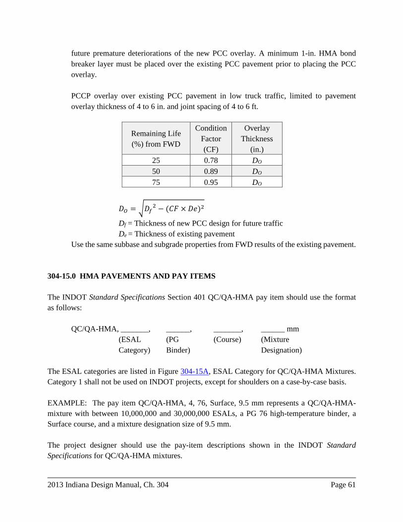
2013 Indiana Design Manual, Ch. 304 Page 61
future premature deteriorations of the new PCC overlay. A minimum 1-in. HMA bond breaker layer must be placed over the existing PCC pavement prior to placing the PCC overlay. PCCP overlay over existing PCC pavement in low truck traffic, limited to pavement overlay thickness of 4 to 6 in. and joint spacing of 4 to 6 ft.
Remaining Life (%) from FWD
Condition Factor (CF)
Overlay Thickness
(in.) 25 0.78 DO 50 0.89 DO 75 0.95 DO
𝐷𝐷𝑂𝑂 = �𝐷𝐷𝑓𝑓2 − (𝐶𝐶𝐶𝐶 × 𝐷𝐷𝐷𝐷)2
Df = Thickness of new PCC design for future traffic De = Thickness of existing pavement
Use the same subbase and subgrade properties from FWD results of the existing pavement. 304-15.0 HMA PAVEMENTS AND PAY ITEMS The INDOT Standard Specifications Section 401 QC/QA-HMA pay item should use the format as follows: QC/QA-HMA, _______, ______, _______, ______ mm (ESAL (PG (Course) (Mixture Category) Binder) Designation) The ESAL categories are listed in Figure 304-15A, ESAL Category for QC/QA-HMA Mixtures. Category 1 shall not be used on INDOT projects, except for shoulders on a case-by-case basis. EXAMPLE: The pay item QC/QA-HMA, 4, 76, Surface, 9.5 mm represents a QC/QA-HMA-mixture with between 10,000,000 and 30,000,000 ESALs, a PG 76 high-temperature binder, a Surface course, and a mixture designation size of 9.5 mm. The project designer should use the pay-item descriptions shown in the INDOT Standard Specifications for QC/QA-HMA mixtures.
Page 62 2013 Indiana Design Manual, Ch. 304
Standard Specifications Section 402 HMA is specified for a small-quantities project or where construction constraints require that the material be placed in narrow widths, non-uniform widths, or drive approaches where density and samples are difficult to obtain. No Section 402 HMA will be specified on mainline or shoulders when the original contract pay item quantities are greater than or equal to 300 tons. For miscellaneous mixtures (Section 402) such as HMA Rumble Strips, HMA for Approaches, HMA for Temporary Pavement, Widening with HMA, the project designer should specify the applicable pay item and mixtures as listed in the INDOT Standard Specifications. An HMA pay item should use the following format: Widening with HMA, Type _______ (Type) The mixture type is determined from ESALs calculated for the project’s pavement design. The type categories for HMA mixtures are listed in Figure 304-15B, Mixture Type for HMA Mixtures. EXAMPLE: The pay item HMA Patching, Type B represents a HMA mixture for the range of 0.3 million ≤ ESAL < 3 million, and Patching. The project designer should use the pay item descriptions shown for HMA mixtures in the INDOT Standard Specifications, Section 401. 304-15.01 Performance Grade (PG) Binder Performance Graded (PG) Binders for QC/QA mixtures are designed based on their performance-related properties determined for the project’s climate (temperature) and location within the pavement structure. A program developed by FHWA’s Long-Term Pavement Performance (LTPP) program, LTPPBind ™ should be used to select the grades of the PG Binder for a specific project. Information related to this software is available at http://www.fhwa.dot.gov/pavement/ltpp/ltppbind.cfm. Base mixtures are designed for a lower high-temperature than the surface and intermediate mixtures. The PG binder is determined using the LTPP Bind program with inputs based on the speed and amount of traffic for the project. For an HMA overlay, the type and condition of the existing pavement should also be considered. For intersections and roundabouts with traffic of more than 3 million ESALs, it is recommended to bump the PG binder grade one grade up, e.g., , if LTPPBIND determines PG 64, then use PG 70.
2013 Indiana Design Manual, Ch. 304 Page 63
PG binders are identified with high and low Celsius temperature values. For example, PG 70-22 identifies 70°C as the high-temperature design value and -22°C as the low-temperature design value. The high-temperature value is the average seven-day maximum pavement temperature. The low-temperature value is the lowest air temperature recorded at the weather station(s) nearest the project site. The binder selection reliability is used to indicate the probability that the design high and low temperatures will not be exceeded during the design life. A value of 64, 70, or 76 should be used for the high-temperature design and a value of -22 will be used for the low-temperature design. The value selected for design high temperature should be evaluated for 98% reliability. However, a design high-temperature value satisfying 90% reliability may be considered for a Traffic Group A roadway (TWRG). The PG binder for a QC/QA project will be identified in the pay item designation in accordance with INDOT Standard Specifications. 304-15.02 HMA Shoulders For an HMA paved shoulder of 4 ft or narrower, the project designer should specify the same HMA pay item designations and thicknesses as those used for the adjacent travel lane. For an HMA paved shoulder wider than 4 ft, the project designer should specify the thicknesses and HMA pay item designations for the appropriate typical section identified in the series of Figures 304-21. Shoulder corrugations should be in accordance with INDOT Standard Specifications Section 302. 304-15.03 HMA for Approaches HMA for Approaches is a mixture designated for a drive, public-road approach, crossover, turn lane, acceleration or deceleration lane, mailbox approach on a non-paved shoulder, etc. It should be used for a short project where the HMA quantity is less than 300 tons and where the paving involves a large amount of handwork or non-paving movement of the paver and rollers. The limits and the pavement section for HMA for Approaches are shown in the INDOT Standard Drawings for drives, public-road approaches, and crossovers. Where the AADT exceeds the amount shown on the Standard Drawings, the HMA pavement section must be determined in accordance with Section 304-14. See INDOT Standard Specifications, Section 610 and 611.
Page 64 2013 Indiana Design Manual, Ch. 304
For a public-road approach, the limits for HMA mixtures for approaches may be extended to include up to an additional 100 ft of pavement to satisfy project requirements. If the project requires more than 100 ft of additional pavement the entire public approach section will be designed based on MEPDG. For an HMA turn lane, HMA acceleration or deceleration lane, HMA wedges for a bridge deck overlay project, or HMA approaches for a bridge-replacement project that require less than 300 tons of HMA material, the pavement will be designed in accordance with Section 304-14 as HMA for Approaches of the type required. For a mailbox approach on a non-stabilized shoulder, HMA for Approaches of the type required, should be used as specified on the INDOT Standard Drawings. 304-15.04 Composite Pavement Rehabilitation HMA over asphalt and PCC composite pavement will be designed to match the existing pavement. If there is existing excessive reflective cracking, the designer needs to obtain enough information to determine where partial depth patching and full depth patching is required. FWD is recommended on composite pavements to determine the structural integrity and the need for undersealing. The longitudinal joint of the widened composite pavement should not be placed in a wheel path of a travel lane. If the existing pavement has open-graded subbase with underdrains, the existing longitudinal underdrain system will be perpetuated with additional outlets added in accordance with Section 304-18. If the existing pavement has dense-graded subbase, underdrains are typically not added. The existing asphalt over PCC composite pavement should be milled in accordance with Section 304-10, and prepared in accordance with the INDOT Standard Specifications, Section 306. 304-16.0 PCC PAVEMENT AND PAY ITEMS The requirements for Portland Cement Concrete Pavement (PCCP) are given in the INDOT Standard Specifications, Section 500. PCCP is constructed on subbase for PCCP (drainable subbase), or dense graded subbase on a prepared subgrade. The subgrade should be designed in accordance with the Geotechnical Report. The geotechnical recommendations may include a soil modification or stabilization process, subgrade-treatment type, or a compacted-aggregate stabilization layer.
2013 Indiana Design Manual, Ch. 304 Page 65
Subbase for PCCP is placed on the prepared subgrade and is composed of 3 in. of coarse aggregate No. 8 on 6 in. of compacted aggregate No. 53. The coarse aggregate No. 8 is a permeable layer that collects and removes water entering the pavement subbase system. The compacted aggregate No. 53 is a dense layer that separates the subgrade from water entering the pavement subbase system. Underdrains must be included where Subbase for PCCP is specified. Dense Graded Subbase is used under miscellaneous PCCP such as a drive, reinforced-concrete bridge approach, etc., or may be used where underdrains are not warranted although in the case where Dense Graded Subbase is used the design life may be reduced to 20 years. Dense Graded Subbase is composed of 6 in. of compacted aggregate No. 53, but is paid for as “Subgrade Treatment, Type IIIA” under driveway pavement. The designed thickness of PCCP determined by the AASHTOware Pavement ME Design software is placed on Subbase for PCCP. The minimum PCCP thickness is 7 in. The transverse joint spacing and dowel bar diameter in the concrete pavement joints are designed in accordance with the MEPDG and are constructed as contraction joints type D-1. The joint spacing should be shortened where necessary to meet a drive, inlet, adjacent lane, etc., so that all joints are continuous across the entire width of pavement including shoulders. The additional D-1 joints should be included in the contract quantities. Non-standard joints are not to be used in a pavement without approval of the Department’s Director of Pavement Division. If a project designer desires to utilize non-standard pavement joints in an individual contract, a submittal should be made to the Director of Pavement Division. Quality Control/Quality Assurance (QC/QA) PCCP pay items and PCCP pay items, as described in the INDOT Standard Specifications, Section 500 are used for a project specifying PCCP. The criteria for using QC/QA-PCCP or PCCP are based on the area of PCC pavement specified. For a project PCCP quantity of 7200 yd2 (one lot) or greater, the pay item should be “QC/QA-PCCP, ___ in.” For a project PCCP quantity of less than 7200 yd2, the pay item should be “PCCP, ___ in.” 304-16.01 PCCP Preventive Maintenance Treatment (CPR) The pavement work on a PCCP overlay project may include milling of the existing pavement, the placement of an overlay, or a combination of these elements. Concrete Pavement Restoration (CPR), of a PCCP may be used where the existing PCCP is considered to be structurally sufficient but has reduced serviceability. CPR alternatives are full or partial depth patching, PCCP profiling, joint resealing, retrofit load transfer, shoulder restoration, slab stabilization (undersealing), longitudinal crack and joint repair, or combinations of these alternatives.
Page 66 2013 Indiana Design Manual, Ch. 304
The condition of the driving lane of PCCP is an indicator of the project’s suitability for CPR. FWD testing and core investigation for “D” cracking at joints should be completed. A PCCP investigation where cores indicate a “D” cracking distress is not a candidate for CPR or PM treatment. Undersealing consists of a localized activity where a fluid material is pumped under the concrete slab to add support and to fill voids under the pavement. PCCP or asphalt over PCC composite pavement should be tested with a FWD as described in Section 304-13.01 to determine size and limits of voids underlying the pavement. PCCP on open graded subbase should not be undersealed. In urban areas utilities may be an issue that prohibits undersealing as this will fill old cracked storm drainage systems and may damage other buried utilities. Pavement designers need to ascertain whether utilities can be avoided during an undersealing operation in urban areas. The cost of the recommended rehabilitation should be compared to the cost of replacing the existing pavement or an alternate rehabilitation technique using life-cycle cost analysis. 304-16.02 Continuously Reinforced Concrete Pavement (CRCP) 304-16.02(01) CRCP Design CRCP has the potential to provide a long-term, zero-maintenance, service life under heavy traffic loadings and challenging environmental conditions, provided proper design and quality construction practices are utilized. See FHWA–HIF-12-039 TechBrief. The AASHTOWare Pavement ME Design software (formerly DARWinME) should be utilized to design a CRCP. The best source for a national overview of CRCP performance is the Long-Term Pavement Performance (LTPP) Program. General Pavement Study (GPS) 5, included 85 CRCP experimental sections in 29 states. CRCP differs from other concrete pavements as follows: 1. CRCP has no active transverse contraction joints, except at ends. 2. Continuous longitudinal reinforcement is provided that results in tight cracks in the
concrete at about 2-ft to 8-ft spacing. Sufficient reinforcement is necessary to keep the cracks tight.
3. CRCP can extend, joint free, for many miles with breaks provided only at structures, such
as bridges.
2013 Indiana Design Manual, Ch. 304 Page 67
CRCP design focuses on managing the cracking that develops so as to reduce the structural distress that may develop as a result of traffic and environmental loadings. These distresses include punchouts, steel rupture, and crack spalling. CRCP design involves determining the proper combination of the following: 1. slab thickness; 2. concrete mixture constituents and properties; and 3. steel reinforcement content and location (critical element). Other important features that a designer must require for a good CRCP design are as follows: 1. provide for sufficient slab edge support (critical element); 2. strengthen or treatment of the subgrade; and 3. provide non-erodible bases that also provide friction that leads to desirable transverse
cracking patterns. Most transverse cracks form at very early ages before a pavement is open to traffic, and cracking may continue for several years after concrete placement. Transverse cracks occur when and where the tensile stress, due to the restrained volume changes in the concrete, exceeds the concrete’s developing tensile strength. New transverse cracks occur roughly at the midpoint between two previously formed cracks, where the maximum concrete stress occurs. Crack formation continues until concrete strength exceeds the stresses due to the restrained volume change. Recognizing that the tensile strength of the concrete and the tensile stresses vary along the length of the slab, the transverse crack spacing pattern is never uniform, but the majority of cracks should be spaced within the desired range of 2 ft to 8 ft. 304-16.02(02) CRCP Reinforcement The use of longitudinal steel reinforcement, typically Grade 60 bars, results in a series of closely spaced transverse cracks. The steel reinforcement is used to control cracking and is spaced, typically between 2 ft and 8 ft, and the amount of opening at the cracks and to maintain high levels of load transfer across them. CRCP should be built with longitudinal reinforcing steel percentages in the range of 0.65 to 0.80 percent; lower in milder climates and higher in harsher climates. Equally important as the percentage of steel content is the bond area between the concrete and the bars, which the Federal Highway Administration recommends at a minimum of 0.030 square inch per cubic inch of concrete (FHWA 1990). Design steel content provides a balance between crack width (< 0.02 in. at surface over design life), crack spacing, and crack load transfer capability.
Page 68 2013 Indiana Design Manual, Ch. 304
Vertical placement of the bars also affects performance--placed too high, the bars may corrode due to inadequate cover; placed too low, the bars are too far away to keep the cracks tight at the surface. The common position of the reinforcement is between ⅓ and ½ the slab thickness measured from the pavement surface (CRSI 2009). Steel bars normally come in standard lengths of 60 ft and must be lap-spliced to form a continuous longitudinal mat. The lap-splicing patterns should be staggered. Transverse bars are always used to support longitudinal reinforcement. The transverse bars are placed on bar supports. The bars also keep tight any longitudinal cracking that may develop. The vertical position of the bars is set by the supports and diameters of the transverse and the longitudinal bars, and the tolerance is usually up 0.50 in. and down 1.0 in. The chairs or bar supports must be stable and should not sink into the base prior to paving. Horizontal spacing tolerances are less stringent, but it is important that longitudinal bar placement does not impede placement or consolidation of the concrete. The horizontal bar spacing tolerance should be 1.0 in. The development of continuous bar supports, commonly known as transverse bar assemblies (TBAs), has led to speedier placement of the steel mat. A TBA is a transverse bar to which are welded steel supports which serve as chairs, and U-shaped clips. The spacing of the clips along the bar matches that required of the longitudinal bars. When the longitudinal bars are installed into the clips, the clips hold them in position vertically and keep them from moving transversely, while allowing a bit of longitudinal movement.
2013 Indiana Design Manual, Ch. 304 Page 69
304-16.02(03) CRCP Edge Support/Shoulders Proper edge support (tied concrete shoulder) adjacent to mainline CRCP reduces wheel load stresses and deflections and the occurrence of punchouts, reduces longitudinal joint maintenance issues; reduces shoulder maintenance needs, and provides support for traffic detours. To be considered a “widened slab”, research indicates that the slab needs to have a minimum width of 13 ft to minimize longitudinal cracking (INDOT uses 14 ft), and be striped to 12 ft to significantly reduce the stresses and deflections due to heavy truck traffic near the pavement edge. Current best practice to improve the edge support is to use a tied-concrete shoulder or a widened outside lane, a “widened slab” with an asphalt shoulder. 304-16.02(04) CRCP End Treatments
Two types of end treatments at structures are used for CRCP: 1. Wide flange beam joint. This treatment serves as an expansion joint and allows the end to
move freely as the concrete expands and contracts with changing temperature. 2. Anchor lugs. This treatment, consisting of several lugs below the slab and tied unto the
slab end, attempts to restrain any movement from taking place at the ends. A simple conventional doweled expansion joint may be used as part of the approach slabs at a structure. 304-16.02(05) CRCP Concrete Curing CRCP can be placed both during the daytime and nighttime hours. Paving at night when daytime temperatures would be very hot has been shown to result in better performing CRCP because the development of heat of hydration and high ambient daytime temperatures due to solar radiation do not coincide. Better temperature specifications and temperature management during paving are leading to better performing CRCP. Specifications limit the concrete temperature to a range of 50° F to 90° F. Other measures to reduce heat may include changing the concrete mixture constituents and proportions for lower heat of hydration, specifying wetting of the base and steel bars just in front of the paver, and whitewashing the asphalt base prior to placement of the reinforcement, as long as it does not reduce bonding and friction with the CRCP, as this will greatly affect crack spacing and width. The use of HIPERPAV® software at the construction site can provide relative information regarding expected CRCP cracking patterns if there are drastic
Page 70 2013 Indiana Design Manual, Ch. 304
temperature changes so that various remediation measures, e.g., changes in concrete mixture, curing techniques, etc. can be implemented. 304-17.0 MISCELLANEOUS PAVEMENT PROJECT ELEMENTS 304-17.01 Subgrade A prepared subgrade is required before construction of the pavement. Subgrade is the upper portion of the natural ground or constructed embankment upon which the pavement structure and shoulders are to be constructed. A geotechnical investigation is required for new pavement, reconstructed pavement, rubblized concrete, cracked and seated concrete, or widening (mainline or shoulder). The geotechnical investigation may not be required for a one- or two-layer overlay, PM, or surface preservation treatment projects. The geotechnical investigation should be requested by the district Pavement Engineer, project manager, or the consultant’s pavement designer or project engineer. A full geotechnical investigation usually takes 120 calendar days. Specified subgrade treatments shall be in accordance with recommendations in the Geotechnical Report and INDOT Standard Specifications Section 207. 304-17.02 Temporary Pavement Temporary pavement is used for maintenance of traffic (MOT) and will take the form of: 1. temporary cross-over; 2. temporary run-around, see Standard Drawings 713-TCTR-01 and -04; 3. temporary widening (auxiliary lane); or 4. temporary ramp. Temporary pavement should be designed using AASHTOWare Pavement ME Design software considering 95% reliability and minimum 2 construction seasons or as specified in the pavement design request. The temporary pavement should be designed with the proper geometric and design speed considerations, i.e., cross slope, superelevation, profile grade, etc. The subgrade should be prepared based on Geotechnical Report recommendation. If the Geotechnical Report is not available, use Resilient Modulus of 3000 psi for prepared subgrade, 1500 psi for the natural subgrade and Type IIIA subgrade treatment. If a temporary pavement is to be used as a permanent shoulder, pay items should not be temporary pavement, but should be QC/QA HMA.

2013 Indiana Design Manual, Ch. 304 Page 71
304-17.03 Driveways Standard Drawings E 610-DRIV-01 through -07. 304-17.04 U-Turn Median Opening Standard Drawing E 610-UTMO-01. 304-17.05 Public Road Approach The pavement design for a public-road-approach pavement should be in accordance with the INDOT Standard Drawings. An individual pavement recommendation for a public road approach is required only where the AADTT exceed the values listed in the INDOT Standard Drawings. 304-17.06 Bridge Deck Overlay An individual pavement design is not required for a bridge deck overlay project when the maintenance of traffic does not utilize the shoulder. If the shoulder is utilized for maintenance of traffic a pavement design is required. For both cases, the district Pavement Engineer will provide the pavement design recommendations. 304-17.07 Seal Coat Seal coat, or chip seal, is used to seal a shoulder, to seal a very low-traffic-volume roadway, or during construction to bond loose material to allow construction traffic to use the surface. The requirements for seal coat are shown in the INDOT Standard Specifications, Section 404. 304-17.08 Prime Coat Prime coat is only required for a rubblized base that is to be overlaid. The prime coat binds the top portion of the rubblized base with the first HMA layer so that the HMA material will not slide relative to the base material during compaction of the HMA. Prime coat shall not be specified to be placed on a compacted aggregate before an HMA Base or Intermediate is laid on subgrade. Prime coat should be specified on chemically modified soil or soil compacted to density and moisture requirements before an HMA Base or Intermediate is laid on subgrade. This must be
Page 72 2013 Indiana Design Manual, Ch. 304
specified in the Pavement Design Memorandum. The requirements for prime coat are shown in the INDOT Standard Specifications, Section 405. 304-17.09 Tack Coat Tack coat is required beneath each course of HMA material that is placed on an existing pavement or newly-constructed HMA course. The tack coat binds the new HMA material to the material already in place. HMA or PCCP is to be tacked prior to placement of an HMA mixture. The requirements for tack coat are shown in the INDOT Standard Specifications, Section 406. 304-17.10 Base Seal Base seal is used to help maintain the integrity of the OG layer. Prior to placing an open-graded mixture, the underlying HMA course (HMA Base) shall have a full width base seal applied in accordance with INDOT Standard Specifications, Section 415. The base seal materials are applied to the pavement surface uniformly with a distributor at a relatively high application rate of 0.22 ± 0.02 gal/sq yd. The base seal materials also must cure a minimum of two hours after application before resuming paving operations. 304-17.11 Curbs and Shoulders PCCP is constructed with curb and gutter sections, integral concrete curbs, a widened outside lane with HMA shoulder, or tied full-depth concrete shoulders. The curb and gutter sections, integral curbs, widened outside lane, or tied shoulders stiffen the outside edge of pavement to reduce deflections. D-1 joints are required across the entire PCCP mainline. Compacted aggregate or geotextile should be specified alongside PCCP curbs or shoulders to prevent erodible material from infiltrating the underdrain system. The typical sections for PCCP shoulders are included in the series of Figures 304-21. 304-17.12 Reinforced-Concrete Bridge Approach (RCBA) The requirements for an RCBA are shown in the INDOT Standard Specifications, Section 609. The RCBA is constructed on dense-graded subbase on prepared subgrade. An RCBA is used at a bridge to transition from PCC or HMA pavement to the bridge deck or mudwall. For PCCP, the RCBA spans from the sleeper slab to the pavement ledge on the mudwall.
2013 Indiana Design Manual, Ch. 304 Page 73
For HMA pavement, the RCBA spans from the end of the HMA pavement to the pavement ledge on the mudwall. The RCBA is reinforced to account for unsupported conditions due to settlement at the end bent or abutment. The RCBA and reinforcing-steel details are shown on the INDOT Standard Drawings. 304-18.0 UNDERDRAINS An underdrain is a system of perforated pipe and coarse aggregate installed longitudinally in the vicinity of a pavement edge. The purpose of an underdrain is to remove water from the subgrade and the pavement structure. An Underdrain Table is required in the plans. The designer should consult the Geotechnical Investigation Report for the need for subsurface drains. The pavement designer must determine whether underdrains are a benefit to the life of the pavement and are cost effective. See INDOT Standard Specifications, Section 718. It is possible that underdrains may not be warranted; however, subsurface drains may be required on a project to remove ground water as required by the Geotechnical Investigation Report. 304-18.01 Definitions Aggregate for Underdrains. Coarse aggregate No. 8 or coarse aggregate, No. 9 used to backfill an underdrain pipe trench. Dual-Access Underdrain. A run of underdrain that features outlet pipes connected to both ends of the underdrain pipe. The dual-access outlet pipes are installed to provide access to the underdrain pipe for inspection and maintenance purposes. Geotextiles for Underdrain. An engineered geotextile fabric used to prevent soil particles from contaminating an underdrain pipe and aggregate for underdrains. See INDOT Standard Specifications, Section 900 for geotextile materials. HMA for Underdrains. An open-graded HMA used to patch an existing asphalt shoulder over a retrofitted underdrain pipe or an outlet pipe. Intercept Elevation. The invert elevation at the connection between an underdrain pipe and a PVC connection at a drainage structure or outlet pipe. Intercept Station. The station at which the connection between an underdrain pipe and a Polyvinyl Chloride (PVC) connection at a drainage structure or outlet pipe occurs.
Page 74 2013 Indiana Design Manual, Ch. 304
Obstacle. A project feature, such as a paving exception or bridge, culvert, that prevents the continuous installation of underdrain pipe. Outlet Elevation. The invert elevation of an outlet pipe or PVC pipe connection where the collected water leaves the outlet pipe. Outlet Pipe. A non-perforated pipe that conveys water collected by the underdrain pipe to a side ditch, median ditch, or drainage structure. An outlet pipe may also be installed at the high end of an underdrain pipe to create a dual-access underdrain. Outlet Protector. A concrete slab constructed on a sideslope to protect the outlet-pipe end. Outlet Station. The station where an outlet pipe discharges to the sideslope or is connected to a drainage structure. Retrofit Underdrain. An underdrain pipe installed along an existing pavement edge in conjunction with a pavement rehabilitation operation, such as rubblization, cracked and seated, or overlaying. Rodent Screen. Metal mesh screen fabricated in accordance with the specifications that fits inside the outlet pipe to prevent rodents and debris from entering the underdrain system. Single-Access Underdrain. A run of underdrain that features an outlet pipe connected to the low end of the underdrain pipe only. Special Underdrain. An underdrain pipe installed at a specified slope that is not parallel to the pavement profile or a constant depth that differs from that shown in the series of Figures 304-21. Tangent Grade. The specified grade between two adjacent points of vertical inflection (PVIs) on the vertical alignment of the proposed pavement. Underdrain Pipe. A perforated pipe installed at the bottom of a longitudinal or transverse underdrain trench. Underdrain Run. An individual segment of underdrain pipe and its associated outlet pipe or pipes. Underdrain System. The system that collects water from the subgrade and pavement structure and conveys it to the drainage system. Underdrain-system elements include the underdrain trench, underdrain pipe, aggregate for underdrains, geotextiles for underdrain, outlet pipe, rodent screen, outlet protector etc.
2013 Indiana Design Manual, Ch. 304 Page 75
Video Inspection. The process of inspecting an individual underdrain run after installation using a video camera. Video inspection can also be performed on existing underdrains to find damaged portions that need repaired. 304-18.02 Existing Underdrain Perpetuation A roadway with existing underdrains should have all outlet pipes perpetuated as part of the work. The project designer should determine if any existing underdrains, longitudinal or transverse, are present, and locate all existing outlet pipes to evaluate them for needed maintenance or repair. Required repair or maintenance, such as unearthing and replacing an outlet pipe or reconstructing an outlet protector, should be included in the proposed work. If there are retro-fit underdrains on a project, the designer should determine if any existing underdrains are present and locate all existing outlet pipes to coordinate them with any new outlets proposed. 304-18.03 Underdrain Warrants Underdrains are required for each project, including a LPA project that satisfies any of the conditions as follows: 1. new pavement or reconstructed pavement with a design-year Average Annual Daily Truck
Traffic (AADTT) volume of 100 per day or greater, and a length of at least 1 center lane mile; or
2. the pavement sections adjacent to the project area have existing underdrains; or 3. where specific geotechnical conditions are identified that require subsurface drains as
stated in the Geotechnical Investigation Report. Underdrains are also required when using Subbase for PCCP, HMA class OG mixture QC/QA-HMA 5, 76, Intermediate, OG 19.0 mm, or where an existing PCCP is to be cracked and seated or rubblized. Underdrains are not typically constructed on a functional or preventive maintenance treatment project, except where existing underdrains are not performing adequately.
Page 76 2013 Indiana Design Manual, Ch. 304
304-18.04 Design Criteria Proper design of the underdrains is critical for the life of the pavement. The following items shall be addressed in the design of underdrains. 304-18.04(01) Slope 1. Underdrain Pipe. Where the tangent grade is 0.2% or steeper, the underdrain pipe will be
installed at a fixed depth below the pavement. Where the tangent grade is flatter than 0.2% or if the Geotechnical Report indicates that the underdrain pipe should be installed at a depth other than that shown in the series of Figures 304-21, special underdrains are required. The special underdrain slope should be 0.2% or steeper.
2. Outlet Pipe. The flattest outlet pipe slope permitted is 0.3%. 304-18.04(02) Size 1. Underdrain Pipe. Construction of new pavement requires underdrain pipe of 6-in.
diameter. Rehabilitation of existing pavement may utilize underdrain pipe of 4-in. diameter.
2. Outlet Pipe. Outlet pipe of 6-in. diameter is required. If underdrain pipe of 4-in. diameter
must be used, outlet pipe fittings will be utilized to increase the outlet pipe size to 6-in. 304-18.04(03) Outlet Spacing An outlet pipe is required at the low point of a sag vertical curve. It is also required at other low points encountered along the vertical alignment, such as the project beginning or ending point, or at an obstacle location. Additional outlet pipes are likely to be required throughout the project limits. The maximum underdrain-pipe length should not exceed 600 ft. If the proposed underdrain-pipe length is greater than 400 ft, a dual-access underdrain is required. If the outlet spacing results in an underdrain-pipe length that is 400 ft or less, a single-access underdrain should be utilized.
2013 Indiana Design Manual, Ch. 304 Page 77
304-18.04(04) Location An underdrain, where warranted in accordance with Section 304-18.03, should be constructed along each pavement edge. The underdrain should be continuous through each intersection, ramp, turn lane, taper, etc., and should be located in the pavement section as shown in the series of Figures 304-21. For an approach where an underdrain is warranted in accordance with Section 304-18.03, the underdrain should extend from the mainline underdrain to the limit of the new approach pavement. 1. Underdrain Pipe. The underdrain-pipe location within each proposed cross section should
be as shown in the series of Figures 304-21.
If an inlet, catch basin, manhole, or similar structure is located along the alignment of an underdrain pipe, the underdrain pipe may be connected directly to the drainage structure. The connection should be at least 6 in. above the structure invert elevation and a rodent screen should be placed on the outlet end of the underdrain pipe.
A direct connection of an underdrain pipe to a pipe culvert or a precast-concrete culvert should be avoided.
2. Outlet Pipe. The connection between an outlet pipe and an underdrain pipe should be as
shown on the INDOT Standard Drawings. 90-deg elbows or tees should not be utilized in these connections.
One of the 45-deg elbows may be omitted if necessary to provide a satisfactory outlet.
Separate outlet pipes should be provided for each underdrain pipe. Outlet pipes for adjacent underdrain pipes at a sag-vertical-curve low point or for adjacent dual-access underdrains should be installed in a common trench as shown on the INDOT Standard Drawings. Outlet pipes installed in a common trench should outlet at the same elevation. The outlet elevation should be at least 2 ft above the flowline elevation of a side ditch, 1 ft above the flowline elevation of a median ditch, or 0.5 ft above the invert elevation of an inlet, catch basin, manhole, or similar structure. If an underdrain pipe has no suitable outlet available at an adjacent ditch line or drainage structure, the outlet pipe may be installed under the pavement to an acceptable outlet on the opposite side of the roadway. The outlet-pipe installation should be designed so as not to conflict with the underdrain-pipe installation along the opposite pavement edge.
Page 78 2013 Indiana Design Manual, Ch. 304
304-18.04(05) Backfill 1. Underdrain Pipe. Aggregate for underdrains is used to backfill an underdrain pipe trench.
A retrofit underdrain requires HMA for underdrains for patching an existing asphalt shoulder above the underdrain-pipe trench as shown on the INDOT Standard Drawings.
2. Outlet Pipe. Outlet-pipe backfill includes structure backfill and suitable material placed as
shown on the INDOT Standard Drawings. HMA for underdrains is required for patching an existing asphalt shoulder above the outlet-pipe trench associated with a retrofit underdrain as shown on the INDOT Standard Drawings.
304-18.04(06) Outlet Protector An outlet protector is required at each location where an outlet pipe intersects a median or side slope. An outlet protector may contain two outlet pipes. The INDOT Standard Drawings series E718-UNDR includes details for each available protector type. Figure 304-18A, Outlet Protector Slope Limits, includes acceptable slopes for construction of each outlet-protector type. The outlet protector selected should be the largest protector appropriate for the proposed slope that can be constructed considering all conflicts to the outlet location. Type 1 outlet protectors should typically be used on new alignment projects for the side slope outlets. The smaller Type 2 and Type 3 outlet protectors should only be used for median outlets and in limited applications on these type projects. 304-18.04(07) Geotextiles for Underdrain There are two applications where geotextiles are used in conjunction with underdrain-pipe installation. The first application is as an underdrain-pipe trench liner. Trench lining should be used only if the Geotechnical Investigation Report recommends such an installation. The second application for geotextile is to prevent the contamination of the underdrain-pipe backfill during the construction of embankment behind a concrete curb. Installation of the geotextile should be as shown in the series of Figures 304-21, and is required in conjunction with curb construction above an underdrain pipe. Geotextile should be required everywhere an open graded drainage material is
2013 Indiana Design Manual, Ch. 304 Page 79
in contact with an in situ soil, compacted aggregate shoulder wedge, or other material that has fine grain particles with the ability to infiltrate and clog the drainage layer. 304-18.04(08) Video Inspection Video inspection of an underdrain system should be included in each new construction as well as rehabilitation project with at least 3,000 ft of underdrain pipe. The contract quantity should be as shown in Figure 304-18B, Video Inspection Contract Quantities. 304-18.05 Contract Document Preparation 304-18.05(01) Plans Information related to underdrains should be shown on the plans as follows: 1. Typical Cross Sections Sheet.
a. The underdrain pipe location as illustrated in the series of Figures 304-21.
b. Underdrain-pipe trench and backfill details. 2. Plan and Profile Sheet. Special-underdrain limits and slopes should be shown on the profile
portion of the sheet. 3. Detail Sheets. All project-specific details should be shown on these sheets. 4. Underdrain Table.
a. Underdrain Pipe.
1) Beginning and ending stations 2) Flowline elevations at beginning and ending stations 3) Pipe size 4) Special-underdrain grade, if applicable 5) Pipe quantity 6) Aggregate for underdrains quantity 7) HMA for underdrains quantity, if applicable
Page 80 2013 Indiana Design Manual, Ch. 304
8) Geotextiles for underdrains quantity, if applicable
b. Outlet Pipe.
1) Outlet station 2) Outlet elevation 3) Intercept station 4) Intercept elevation 5) Outlet protector or structure number at outfall 6) Outlet ditch or drainage structure invert elevation at outfall 7) Pipe quantity 8) Structure-backfill quantity 9) HMA for underdrains quantity
c. Outlet Protectors.
1) Type 2) Location 3) Quantity
304-18.05(02) Specifications Requirements for underdrains are shown in INDOT Standard Specifications, Sections 700 and 900. 304-18.05(03) Standard Drawings Details for underdrains and outlet protectors are shown on the INDOT Standard Drawings series E718-UNDR.
2013 Indiana Design Manual, Ch. 304 Page 81
304-18.05(04) Pay Items The designer should determine the contract quantities for the appropriate pay items associated with the underdrain construction. See Chapter 17. 304-19.0 PREVENTIVE MAINTENANCE Preventive Maintenance (PM) treatments are part of the overall pavement preservation program. A PM project is intended to arrest light deterioration, retard progressive damage, and reduce the need for routine maintenance. A PM treatment typically does not add structural strength to the pavement. The proper time for PM is before the pavement experiences severe distress, structural problems, moisture, or aging-related damage. These activities can be cyclical in nature and may correct minor deficiencies as a secondary benefit. For PM treatment service life, see Figure 304-14A, Pavement Design Life. In considering a PM treatment, the overall program schedule of the pavement section should be considered. To achieve the optimal benefit of the PM treatment, it should not be applied if rehabilitation is planned within the service life of the PM treatment. A PM treatment is not used where the purpose of the project is to correct pavement cross slope, horizontal alignment, vertical alignment, superelevation problems, placement of a turn lane or auxiliary lane, improvement of public-road approach or drive, or guardrail adjustment or repair. A PM project may include incidental enhancements or combinations at an isolated location in accordance with Chapter 56. Regardless of the pavement type, proper drainage is essential to the performance of the pavement. Drainage inspection and cleaning consists of the inspection of drainage structures, e.g., underdrain outlets, ditches, catch basins, inlets, and the cleaning of these structures to maintain or restore the flow of water. The locations of underdrains should be identified and the outlets periodically cleaned. The INDOT Field Operations Handbook provides for drainage inspection and cleaning details. The most commonly used PM treatments are described below. See Figure 304-19A for HMA pavement treatments or Figure 304-19B for PCCP treatments. Further descriptions of available Pavement Preservation Treatments can be found in the INDOT SPR-3114 Treatment Guidelines for Pavement Preservation. A least cost of ownership analysis as described in Section 304-4.0, should be done for each PM project to determine the most economical treatment.
Page 82 2013 Indiana Design Manual, Ch. 304
304-19.01 HMA Pavement PM Treatments A certain amount of partial-depth or full-depth patching may be required in conjunction with HMA PM Treatments. Partial-depth or full-depth patching will consist of complete removal of a deteriorated section of the HMA pavement and patching it with HMA. 1. Crack Sealing and Filling. Crack sealing and filling is the cleaning and sealing or filling
of open cracks or joints in asphalt pavement and shoulders to prevent the entry of moisture and debris. The selection of sealing or filling is based on crack movement and crack deterioration. Moving or working cracks, e.g. transverse crack or reflective crack, is defined as an annual crack opening that moves greater than 0.1 in. vertically or horizontally due to thermal expansion and contraction or stress concentration at pavement overlaying joints. Those types of cracks should be considered for crack sealing. Cracks with an annual crack opening with movement of < 0.1 in. or no annual movement, e.g. longitudinal or longitudinal reflective, should be considered for crack filling. Cracks must be clean and dry and may be routed prior to sealing or filling. The major objective of routing is to provide a uniform and smooth edged rectangular reservoir to let the sealant material adhere better with the asphalt pavement and for allowing the sealant level to remain below the pavement surface, which protects the sealant from traffic and snowplow damage. Therefore, routing is strongly recommended for any crack sealing activity as well as crack filling longitudinal joints. This technique may be used for sealing cracks on a newer composite pavement where reflective cracks have developed. This PM treatment may be periodic once more cracks develop as the pavement ages.
Guidelines for selecting a pavement section for crack sealing and filling are as follows:
a. AADT. Crack sealing and filling may be performed on any roadway regardless of
traffic volume, provided adequate traffic control is provided.
b. Pavement Distresses. Crack sealing and filling may be used to correct low to medium severity surface cracks.
c. Rutting. Crack sealing and filling does not correct rutting.
d. Roughness. Crack sealing and filling does not affect roughness. Roughness is
typically not a consideration for crack sealing.
e. Friction. Friction is typically not a consideration for crack sealing and filling. However, overband crack sealing may lower the friction number (FN).
2013 Indiana Design Manual, Ch. 304 Page 83
f. Surface Aging. Crack sealing and filling does not correct surface aging
deficiencies. 2. Fog Sealing. A fog seal is a method of adding asphalt to an existing pavement surface to
improve sealing or waterproofing, prevent further stone loss by holding aggregate in place, retarding the age hardening of the asphalt, and improve the surface appearance. However, inappropriate use can result in a slick pavement and tracking of excess material. The pavement section should show no structural deficiencies prior to fog sealing. Fog sealing is generally recommended for shoulders or chip sealed surfaces.
Guidelines for selecting a pavement section for fog sealing are as follows:
a. AADT. Typically less than 5,000. However, fog sealing may be considered on a
higher volume road if traffic can be controlled.
b. Pavement Distresses. Low severity environmental-related surface cracks.
c. Rutting. Fog sealing does not correct rutting.
d. Roughness. Fog sealing does not improve roughness.
e. Friction. Fog seal should not be applied to a road with a low FN. Fog seal will reduce FN for a period until the material fully cures.
f. Surface Aging. A fog seal may be used to restore an aged, oxidized, or raveled
surface.
g. Longitudinal joint. Fog seal is required on surface layer over longitudinal joint 24-in. in width per Recurring Special Provision 401-R-581.
3. Seal Coat. Seal coat is the treatment of the pavement surface with liquid asphalt material
and coarse aggregate to prevent deterioration of the surface. Seal coat is often called chip sealing. It provides waterproofing, low-severity crack sealing, and improved friction. The pavement section should show no structural deficiencies prior to chip sealing. Isolated areas with structural deficiencies shall be repaired prior to chip sealing. A previously seal-coated surface may be sealed again.
Page 84 2013 Indiana Design Manual, Ch. 304
Guidelines for selecting a pavement section for seal coat are as follows:
a. AADT. Typically used if less than 5,000. A seal coat may be considered on a higher-volume road if traffic can be controlled, i.e. total road closure, extended lane closures. A seal coat may be specified for the shoulders of any road regardless of AADT.
b. Pavement Distresses. A seal coat will mitigate low to medium severity surface
cracking.
c. Rutting. Seal coat does not correct rutting and should not be used where existing ruts are greater than 0.25 in. Seal coating a road with more than 0.25-in. ruts may lead to wheel path flushing.
d. Roughness. A seal coat will not improve the International Roughness Index (IRI).
e. Friction. A pavement with a low FN may be considered for a chip seal surface
treatment. A seal coat will restore surface friction.
f. Surface Aging. A seal coat may be used to stop future deterioration of an asphalt pavement due to age hardening, oxidation, or minor raveling.
For mainline pavement with AADT over 1,000, asphalt for seal coat type P should be specified.
The type of seal coat should be specified as follows:
a. Type 2, 3, 2P or 3P. These are single-course seal coats appropriate for paved
mainline or shoulders. The P designation indicates that polymer modified asphalt is specified.
b. Type 5, 6, 7, 5P, 6P or 7P. These are double-course seal coats appropriate for
unpaved mainline or unpaved shoulders. The P designation indicates that polymer modified asphalt is specified.
4. Microsurfacing. Microsurfacing is a thin, polymer-modified asphalt emulsion mixture.
Microsurfacing may be used to provide a new wearing course to arrest the oxidation of asphalt pavement, improve friction, or fill ruts. An existing pavement should not have excessive cracking or surface irregularities such as shoving. Cores should be taken to
2013 Indiana Design Manual, Ch. 304 Page 85
determine the thickness and investigate if a stripping condition exists. Core data and life-cycle cost data should be reviewed with the Pavement Division for specific recommendations.
All pavement markings and raised pavement markers must be removed prior to placement of a microsurface. This should be included in the appropriate pavement-marking-removal pay items.
If a pavement cross section has irregularities that will require a leveling course, or ruts greater than 0.25 in. that will require a rut fill course, a multiple course microsurface should be specified. The designer should typically specify a multiple course microsurface. A single course microsurface may be specified in unique situations, such as a nearly new road in excellent condition where the only purpose of the microsurface is to restore friction.
Guidelines for selecting a pavement section for microsurfacing are as follows:
a. AADT. Microsurface may be used without regard to traffic volume.
b. Pavement Distresses. A microsurface may be used on a road with low severity
surface cracks. Cracks will typically reflect through the microsurface in a short time period. Cracks should be sealed prior to the application of microsurface. Cracks wider than ¼ in. may need to be routed prior to sealing.
c. Rutting. Microsurface may be used to correct rutting.
d. Roughness. The IRI should be 130 or less. The pavement should not have severe
distresses indicative of a pavement nearing the end of its life. Microsurfacing will not significantly improve surface roughness.
e. Friction. A pavement with a low FN should be considered for microsurface
treatment. A microsurface will restore surface friction.
f. Surface Aging. A microsurface may be used to stop future deterioration of an asphalt pavement due to age hardening, oxidation, or minor raveling.
5. Ultrathin Bonded Wearing Course. Ultrathin bonded wearing course (UBWC) is a gap-
graded, ultrathin hot-mix asphalt mixture applied over a thick polymer-modified asphalt emulsion membrane. The emulsion membrane seals the existing surface and produces high binder content at the interface of the existing roadway surface. The gap-graded mix is
Page 86 2013 Indiana Design Manual, Ch. 304
placed with the emulsion membrane in one pass. Core data and life cycle cost data should be reviewed with the Director of Pavements for specific recommendations.
All thermoplastic pavement markings and raised pavement markers are to be removed prior to placement of a UBWC. The removal quantities should be included in the appropriate pavement-marking-removal pay-items quantities.
The pay item for UBWC should specify the gradation size as 4.75 mm, 9.5 mm, or 12.5 mm. In most applications, the 9.5mm gradation should be specified.
Guidelines for selecting a pavement section for UBWC are as follows:
a. AADT. UBWC may be used without regard to traffic volume.
b. Pavement Distresses. A UBWC may be used on a road with low to moderate
severity surface cracks. Cracks should be sealed prior to the application of a UBWC. Cracks wider than ¼ in. may require routing prior to sealing.
c. Rutting. UBWC does not significantly correct rutting and should not be specified
where existing ruts are greater than 0.25 in.
d. Roughness. The IRI should be 140 or less. The pavement should not have severe distresses indicative of a pavement nearing the end of its life. UBWC will moderately improve surface roughness.
e. Friction. A pavement with a low FN may be considered for a surface treatment. A
UBWC will restore surface friction.
f. Surface Aging. A UBWC may be used to stop future deterioration of an asphalt pavement due to age hardening, oxidation, or moderate raveling.
6. HMA Inlay or Overlay. A thin HMA inlay (4.75 mm), or milling and filling (up to 2 in.),
consists of milling the existing surface and replacing it with a new asphalt surface to the original surface elevation. A thin HMA overlay (4.75 mm) consists of profile milling or scarifying the existing surface and overlaying it with a new asphalt surface. For PM, the surface condition may have minor defects but should not have significant potholes, depressed cracks, or major distresses. Criteria to be used in considering a thin HMA inlay or overlay are as follows:
2013 Indiana Design Manual, Ch. 304 Page 87
a. AADT. An HMA inlay or overlay may be used without regard to traffic volume.
b. Pavement Distresses. An HMA inlay or overlay will correct low to moderate
severity surface cracks that may be associated with surface corrugations or washboarding.
c. Rutting. An HMA inlay or overlay will correct rutting.
d. Roughness. The IRI must be 150 or less. An HMA inlay or overlay will
significantly improve the surface roughness. The designer should evaluate the condition of the existing pavement and adjust the design life accordingly.
e. Friction. A pavement with a low FN may be considered for an HMA inlay or
overlay surface treatment. An HMA inlay or overlay will restore surface friction.
f. Surface Aging. An HMA inlay or overlay may be used to replace an aged, oxidized, or raveled surface.
7. Hot In-Place Recycling (HIR) is the process of heating and softening the existing asphalt
pavement for processing. HIR is limited in depth to less than 2 in. (50 mm). After heating, the asphalt material is picked up and remixed with admixtures, spread back onto the surface of the roadway, and then compacted, all in one operation. Pavements with structural distresses are not good candidates for HIR. The expected service lives of the various HIR rehabilitation techniques, when undertaking a life-cycle economic analysis, generally fall within the following ranges:
HIR with surface treatment . . . . . . . . 4 - 6 years HIR with HMA overlay . . . . . . . . . . . 7 - 10 years
Criteria to be used in considering a thin HMA inlay or overlay are as follows:
a. AADT. HIR may be used without regard to traffic volume.
b. Pavement Distresses. HIR will address oxidation (aging) and most surface related
distresses, i.e., cracking confined to the surface of the pavement.
c. Rutting. HIR will correct surface rutting.
Page 88 2013 Indiana Design Manual, Ch. 304
d. Roughness. The IRI must be 150 or less. HIR will significantly improve the surface roughness. The designer should evaluate the condition of the existing pavement and adjust the design life accordingly.
e. Friction. A pavement with a low FN may be considered for a HIR surface
treatment. HIR will restore surface friction.
f. Surface Aging. HIR may be used to replace an aged, oxidized, or raveled surface.
8. Cold recycling (CR) reuses the existing asphalt pavement by milling to a depth of 3 to 4 in. (75-100 mm), mixing the millings with a recycling agent (asphalt emulsion), and paving and compacting the cold-recycled mix. CR has been successfully used on pavements with a higher degree of cracking that would normally required removal of the cracked surface and a thick overlay. Instead, the top portion of the existing pavement is recycled, cracks are discontinued and a thin overlay is usually applied over the cold recycled asphalt pavement. Cold recycling which includes both Cold In-Place Recycling (CIR) and Cold Central Plant Recycling (CCPR) is applicable for urban or rural roadways with high or low volumes of traffic. The CIR process calls for milling the existing pavement, mixing various recycling agents into the mixture, and then spreading the material across the pavement width for compacting. The CCPR process is the same except the material is transported to a central plant location for mixing and then is transported back to the site for placement and compaction.
For CR projects, an existing roadway assessment, structural capacity assessment, materials properties assessment, geometric assessment of the existing and proposed sections, constructability assessment, and an economic assessment must be conducted.
The expected service lives of various CR rehabilitation techniques, when undertaking a life-cycle economic analysis, generally fall within the following ranges:
CIR with surface treatment . . . . . . . . . 6 - 10 years CIR with HMA overlay . . . . . . . . . . . . 7 - 20 years CCPR with surface treatment . . . . . . . . 6 - 10 years CCPR with HMA overlay . . . . . . . . . . 12 - 20 years
2013 Indiana Design Manual, Ch. 304 Page 89
Criteria to be used in considering a thin HMA inlay or overlay are as follows: a. AADT. CR may be used without regard to traffic volume; however, maintenance
of traffic (MOT) will have to be considered. A traffic assessment should be performed.
b. Pavement Distresses. CR can rehabilitate cracked pavements which are structurally
sound and have well-drained bases. The CR process destroys existing crack patterns and produces a crack free layer for the new surface course such as an HMA or an asphalt surface treatment. For CR to be effective in mitigating cracking, as much of the existing asphalt pavement layer should be treated as possible. Typically, at least 70 percent of the existing asphalt pavement thickness needs to be treated in order to mitigate the reflection cracking. Treatment depth is also affected by the maximum depth that can be treated at one time.
c. Rutting. CR will correct surface rutting. d. Roughness. The IRI must be 150 or less. CR will significantly improve the surface
roughness. The designer should evaluate the condition of the existing pavement and adjust the design life accordingly.
e. Friction. A pavement with a low FN may be considered for CR and surface
treatment. CR with an overlay will restore surface friction. f. Surface Aging. CR with an overlay may be used to replace an aged, oxidized, or
raveled surface. 304-19.02 PCCP PM Treatments 1. Crack Sealing. Crack sealing consists of the cleaning and sealing of open cracks or joints
in PCCP to minimize the entry of moisture and debris. Cracks must be clean and dry and may be routed prior to sealing. This PM treatment may be periodic once more cracks develop as the pavement ages.
2. PCCP Sawing and Sealing Joints. Contraction joints and longitudinal joints should be
inspected periodically and cleaned and resealed as required. For PM, timely sealing of the joints minimize dirt and moisture from entering the joints. Rigid pavement, 8 to 10 years old, should be inspected. If, on inspection, 10% of the joints have loose, missing, or
Page 90 2013 Indiana Design Manual, Ch. 304
depressed sealant, sawing and sealing of the joints should be considered. The joints should be sawed to remove old sealant and to reshape the joint-seal reservoir.
3. Retrofit Load Transfer. This consists of retrofitting of dowels in jointed PCCP to re-
establish load transfer across random cracks. The pavement performance is improved by keeping the elevation of adjacent panels at the same elevation and stops increases in the IRI due to faulting. This work consists of the cutting of slots, placing new dowels or reinforcing bars, then cementing them into place. The pavement may be profiled to improve smoothness after the retrofit load transfer is complete.
4. Surface Profiling. This is a procedure used to restore or improve pavement rideability by
removing surface defects that develop from traffic loading and environmental conditions. Surface profiling enhances surface friction of an existing pavement surface. The resulting corduroy-like surface provides ample channels for water to escape the surface. Surface profiling is recommended to restore rideability if faulting causes the IRI to exceed 150. A faulted pavement must be repaired with retrofit load transfer prior to surface profiling.
5. Partial-Depth Patching. This is primarily used to improve ride quality. It should be limited
to the upper one third of the concrete-pavement depth. The area to be patched should be sawed, and all unsound material removed prior to placement of patch material.
6. Full-Depth Patching. This consists of complete removal of a deteriorated section of
concrete pavement for a full lane width and patching it with new concrete. Full-depth patching may be used to restore pavement rideability and to replace deteriorated joints and cracks. Full-depth patching details are shown on the INDOT Standard Drawings. Isolated cracked D-joints that have spalled out may be patched; however, patching would be considered a short term fix since the remainder of the joints will soon become distressed . If a pavement is D-joint cracked, a slab-reduction technique and overlay should be used.
7. Underseal. This consists of pumping flowable asphalt or cement material into voids under
concrete pavement. This will stabilize the slab and minimize rocking and pumping, and extend the life of the pavement. Pavements with open-graded subbase should not be undersealed. Falling weight deflectometer (FWD) testing must be done in advance of undersealing to determine locations and material quantities.
8. Slab Jacking. This consists of raising a settled slab to its original profile grade by pumping
flowable material underneath. This technique may be used on one or several panels to restore rideability. Panels should be intact with no mid-panel cracking.
2013 Indiana Design Manual, Ch. 304 Page 91
9. Stitching. This treatment involves drilling and inserting reinforcing steel at approximately 45-deg angles across longitudinal cracks and joints in accordance with the specifications. This technique is used to prevent longitudinal cracks or joints from faulting.
304-20.0 LIFE-CYCLE COST ANALYSIS (LCCA) Life-Cycle Cost Analysis is an economic evaluation technique that builds on the principles of economic analysis to evaluate the overall long-term solutions for each type of project. LCCA considers initial and future agency, user, and other relevant costs over the life of alternatives discounted to provide comparative costs. This technique allows a project’s cost to be compared over a specified time period. The selection of design alternatives should be made based on an LCCA sensitivity analysis for pavement life costs. This section provides the methodology to perform an LCCA for a pavement project. Resources are available for further explanation of LCCA, such as FHWA SA-98-079, Life-Cycle Cost Analysis in Pavement Designs. 304-20.01 General Requirements An LCCA will be completed on each alternative for a New Alignment, Reconstruction, or Rehabilitation (Structural) project. In the simplest situation, an LCCA evaluates costs associated with two or more particular strategies or design scenarios over an analysis period including the initial construction and at least one succeeding rehabilitation activity. These costs for the alternate scenarios or money flows are discounted to the present time. A comparison of the net present value of the scenarios is made to provide information regarding one of the factors involved in the selection of a pavement design. The economic evaluation of two feasible design strategies or design scenarios has no relation to the method of financing, or the total cost of the project. Inflation is not a factor in the evaluation since two or more scenarios’ cash flows are being compared over the same time period with presumably the same inflation effects. Constant real dollars should be used in the LCCA, and then the budget analysis should decide funding sources, inflation rate, and cash-flow requirements. An LCCA will be required for a New Alignment, Reconstruction, or Rehabilitation (Structural) project with mainline pavement of more than 10,000 yd2 for determination of pavement type. A LCCA should be completed for all projects where costs of different equitable treatments are close (≤ 10% difference). A least cost of ownership analysis, (cost analysis = $/lane/mile/year) is also
Page 92 2013 Indiana Design Manual, Ch. 304
required for each treatment identified in Section 304-19.0 to compare preventive maintenance preservation treatments with differing design lives. See Figure 304-14A. Two scenarios being evaluated with a total net present value within 10% difference (15% for a preservation project with an initial cost as calculated for a cost analysis of less than $750,000) are considered to be essentially the same. Other factors should be used to make the final selection such as initial costs, constructability, work-zone traffic control, and user delay costs. 304-20.02 Definitions 304-20.02(01) Analysis Period The analysis period is the number of years over which the pavement-life-cycle analysis is conducted. The analysis period should include the initial pavement cost and the cost of at least one subsequent rehabilitation. The analysis period should be at least 50 years in comparing new pavements. In comparing treatments with lesser design lives the number of years may be less. 304-20.02(02) Discount Rate The discount rate is used to equate the cash flows to present worth and determine Equivalent Uniform Annual Cost (EUAC). For general purposes, a 4% discount rate can be assumed. However, a range of rates from 0% to 10% can be used to determine if the alternate scenarios are discount-rate sensitive. The results of the sensitivity analysis should be shown. See FHWA SA-98-079. 304-20.02(03) Equivalent Uniform Annual Cost (EUAC) The EUAC is the combining of initial capital costs and all future expenses into equal annual payments over the analysis period.
Where: PW = present worth i = discount rate n = number of years from year zero.
( ) ( )( )
−++
=11
1n
n
iiiPWEUAC
2013 Indiana Design Manual, Ch. 304 Page 93
304-20.02(04) LCCA Design Life LCCA design life is the estimated service life of the pavement. The design life shown in Figure 304-14A, Pavement Design Life, should be used for the initial, maintenance, or rehabilitation option. The design life of the pavement should be varied to test the LCCA for sensitivity based on the existing pavement condition, past performance, or the condition of the drainage system. The design life used for the sensitivity analysis should be documented. The Office of Pavement Engineering will maintain a listing of historical bid summaries associated with pavement construction, rehabilitation, and maintenance contract costs identified as part of the proposed LCCA. The pavement designer should utilize these costs to compare life-cycle costs of different pavement treatments. 304-20.02(05) Life-Cycle Cost A factor in identifying and performing economic analyses of alternatives in the design of new pavement construction or the repair and rehabilitation of existing pavement is the life cycle of the alternative under consideration. The life-cycle cost includes the initial capital cost of construction, future maintenance, and future rehabilitation cost estimates. The life-cycle cost may also include user-delay costs during construction and rehabilitation, user vehicle operating and accident expenses, engineering fees, or other expenditures over the life of the pavement. It may also include the residual value, or salvage value of the pavement, at the end of the analysis time period. The pavement designer should use the service lives as shown in Figure 304-14A for the rehabilitation alternatives over the life of the pavement. The cost of work-zone traffic control and the cost of user delays during construction between designs may have a significant effect on the analysis. These costs should be quantified for the designs. LCCA costs can include the following:
Page 94 2013 Indiana Design Manual, Ch. 304
1. Agency Costs. These include the following:
a. initial construction costs; b. future construction or rehabilitation costs, e.g., overlays, seal coats, or
reconstruction; c. maintenance costs which recur throughout the design period; d. salvage return or residual value at the end of the design period, which may be a
negative cost; e. engineering and administration costs; and f. traffic-control costs if they are involved.
2. User Costs. These include the following:
a. travel time; b. vehicle operation; c. accidents; d. discomfort; and e. time delay and extra vehicle operating costs during resurfacing or major
maintenance 304-20.02(06) Present Worth (PW) The PW is the value of money at year zero of future expenditures. The future cash flow is discounted by the discount rate to determine PW. The equation for the present worth of a future overlay is as follows:
( )
+= ni
FPW1
1
Where: F = future construction cost i = discount rate n = number of years from year zero. Note: INDOT uses probabilistic LCCA and present value for pavement alternative analysis, not EUCA.
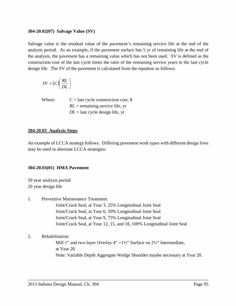
2013 Indiana Design Manual, Ch. 304 Page 95
304-20.02(07) Salvage Value (SV) Salvage value is the residual value of the pavement’s remaining service life at the end of the analysis period. As an example, if the pavement surface has 5 yr of remaining life at the end of the analysis, the pavement has a remaining value which has not been used. SV is defined as the construction cost of the last cycle times the ratio of the remaining service years to the last cycle design life. The SV of the pavement is calculated from the equation as follows:
( )
=
DLRLCSV
Where: C = last cycle construction cost, $ RL = remaining service life, yr DL = last cycle design life, yr 304-20.03 Analysis Steps An example of LCCA strategy follows. Differing pavement work types with different design lives may be used in alternate LCCA strategies: 304-20.03(01) HMA Pavement 50 year analysis period 20 year design life 1. Preventive Maintenance Treatment:
Joint/Crack Seal, at Year 3, 25% Longitudinal Joint Seal Joint/Crack Seal, at Year 6, 50% Longitudinal Joint Seal Joint/Crack Seal, at Year 9, 75% Longitudinal Joint Seal Joint/Crack Seal, at Year 12, 15, and 18, 100% Longitudinal Joint Seal
2. Rehabilitation: Mill 1” and two-layer Overlay 4” =1½” Surface on 2½” Intermediate, at Year 20 Note: Variable Depth Aggregate Wedge Shoulder maybe necessary at Year 20.
Page 96 2013 Indiana Design Manual, Ch. 304
3. Preventive Maintenance Treatment: Joint/Crack Seal, at Year 23, 25% Longitudinal Joint Seal Joint/Crack Seal, at Year 26, 50% Longitudinal Joint Seal Joint/Crack Seal, at Year 29, 75% Longitudinal Joint Seal Joint/Crack Seal, at Year 32, 100% Longitudinal Joint Seal
4. Preventive Maintenance Treatment: Mill 1” and Overlay 1½” Surface, with 1% full-depth HMA patching based on project area, at Year 35
5. Preventive Maintenance Treatment: Joint/Crack Seal, at Year 38, 25% Longitudinal Joint Seal Joint/Crack Seal, at Year 41, 50% Longitudinal Joint Seal
6. Preventive Maintenance Treatment: Mill 1” and Overlay 1½” Surface, with 1% full-depth HMA patching based on project area, at Year 44
7. Preventive Maintenance Treatment:
Joint/Crack Seal, at Year 47, 25% Longitudinal Joint Seal End LCCA, Salvage Value at Year 50 = $0.00 (3 years of Mill and Fill treatment remain) 304-20.03(02) PCCP 50 year analysis period 30 year design life 1. Preventive Maintenance Treatment:
Transverse and Longitudinal Joint Seal, at Years 8, 16, and 24
2. Rehabilitation: Milling, scarification/profile and HMA two layer Overlay 4” =1½” Surface on 2½” Intermediate, with 3% patching based on D-1 Joint quantity, at Year 30
3. Preventive Maintenance Treatment: Joint/Crack Seal, at Year 33, 25% Longitudinal Joint Seal Joint/Crack Seal, at Year 36, 50% Longitudinal Joint Seal
2013 Indiana Design Manual, Ch. 304 Page 97
Joint/Crack Seal, at Year 39, 75% Longitudinal Joint Seal
4. Preventive Maintenance Treatment: Mill 1” and Overlay 1½” Surface, with 1% full-depth composite patching and with 3% partial-depth HMA patching based on D-1 Joint quantity, at Year 42
5. Preventive Maintenance Treatment: Joint/Crack Seal, at Year 45, 25% Longitudinal Joint Seal Joint/Crack Seal, at Year 48, 50% Longitudinal Joint Seal
End LCCA, Salvage Value at Year 50 = $0.00 An LCCA example and major projects’ PCCP and HMA unit prices are available on the Pavement Engineering section of Standards and Specifications webpage, http://www.in.gov/dot/div/contracts/standards/. 304-21.0 TYPICAL PAVEMENT SECTIONS 304-21.01 HMA Pavement Typical HMA mainline pavement sections are shown in Figures 304-21A through 304-21G. 304-21.02 PCC Pavement Typical PCC mainline pavement sections and joint locations are shown in Figures 304-21P through 304-21R. 304-21.03 Miscellaneous Pavement Sections and Details Underdrain details are shown in Figures 304-21 I, 304-21J, 304-21K, 304-21 O, 304-21T, 304-21U, 304-21V, and 304-21Y. Ramp sections are shown in Figures 304-21H and 304-21S. Concrete-curb sections are shown in Figures 304-21K, 304-21L, 304-21M, 304-21N, 304-21 O, 304-21R, 304-21V, and 304-21Z.
Page 98 2013 Indiana Design Manual, Ch. 304
PCCP Longitudinal Joint options on median shoulder sections are shown in Figure 304-21W. Safety Edge sections are shown in Figure 304-21X. Aggregate pavement section is shown in Figure 304-21AA. Parking lot sections are shown in Figure 304-21BB. Patching sections are shown in Figure 304-21CC, 304-21DD, 304-21EE, and 304-21FF. 304-22.0 PAVEMENT DESIGN REQUEST AND INSTRUCTIONS A Pavement Design Request should be submitted to the Pavement Design Coordinator. An editable version of the Pavement Design Request and instructions are available for download from the Department’s website at www.in.gov/dot/div/contracts/design/dmforms/. An incomplete Pavement Design Request will be returned without review.
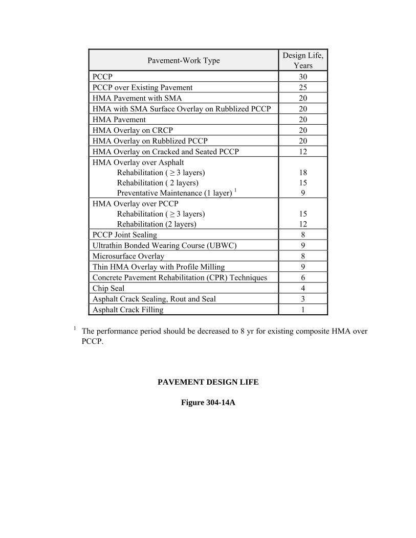
Pavement-Work Type Design Life,
Years PCCP 30 PCCP over Existing Pavement 25 HMA Pavement with SMA 20 HMA with SMA Surface Overlay on Rubblized PCCP 20 HMA Pavement 20 HMA Overlay on CRCP 20 HMA Overlay on Rubblized PCCP 20 HMA Overlay on Cracked and Seated PCCP 12 HMA Overlay over Asphalt Rehabilitation ( ≥ 3 layers) Rehabilitation ( 2 layers) Preventative Maintenance (1 layer) 1
18 15 9
HMA Overlay over PCCP Rehabilitation ( ≥ 3 layers) Rehabilitation (2 layers)
15 12
PCCP Joint Sealing 8 Ultrathin Bonded Wearing Course (UBWC) 9 Microsurface Overlay 8 Thin HMA Overlay with Profile Milling 9 Concrete Pavement Rehabilitation (CPR) Techniques 6 Chip Seal 4 Asphalt Crack Sealing, Rout and Seal 3 Asphalt Crack Filling 1
1 The performance period should be decreased to 8 yr for existing composite HMA over
PCCP.
PAVEMENT DESIGN LIFE
Figure 304-14A
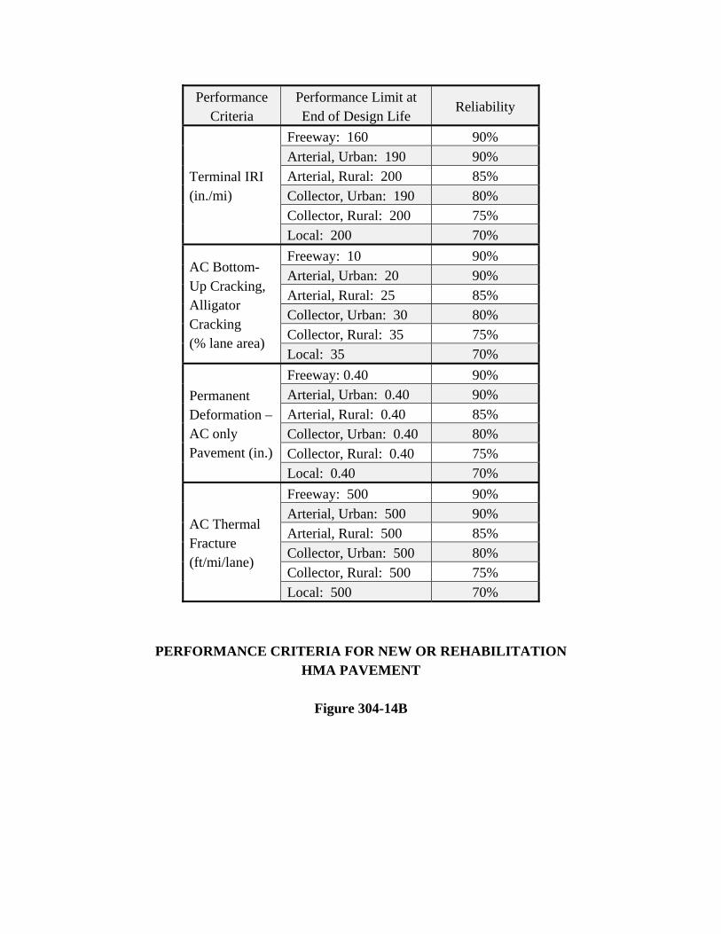
Performance Criteria
Performance Limit at End of Design Life
Reliability
Terminal IRI (in./mi)
Freeway: 160 90% Arterial, Urban: 190 90% Arterial, Rural: 200 85% Collector, Urban: 190 80% Collector, Rural: 200 75% Local: 200 70%
AC Bottom- Up Cracking, Alligator Cracking (% lane area)
Freeway: 10 90% Arterial, Urban: 20 90% Arterial, Rural: 25 85% Collector, Urban: 30 80% Collector, Rural: 35 75% Local: 35 70%
Permanent Deformation – AC only Pavement (in.)
Freeway: 0.40 90% Arterial, Urban: 0.40 90% Arterial, Rural: 0.40 85% Collector, Urban: 0.40 80% Collector, Rural: 0.40 75% Local: 0.40 70%
AC Thermal Fracture (ft/mi/lane)
Freeway: 500 90% Arterial, Urban: 500 90% Arterial, Rural: 500 85% Collector, Urban: 500 80% Collector, Rural: 500 75% Local: 500 70%
PERFORMANCE CRITERIA FOR NEW OR REHABILITATION HMA PAVEMENT
Figure 304-14B
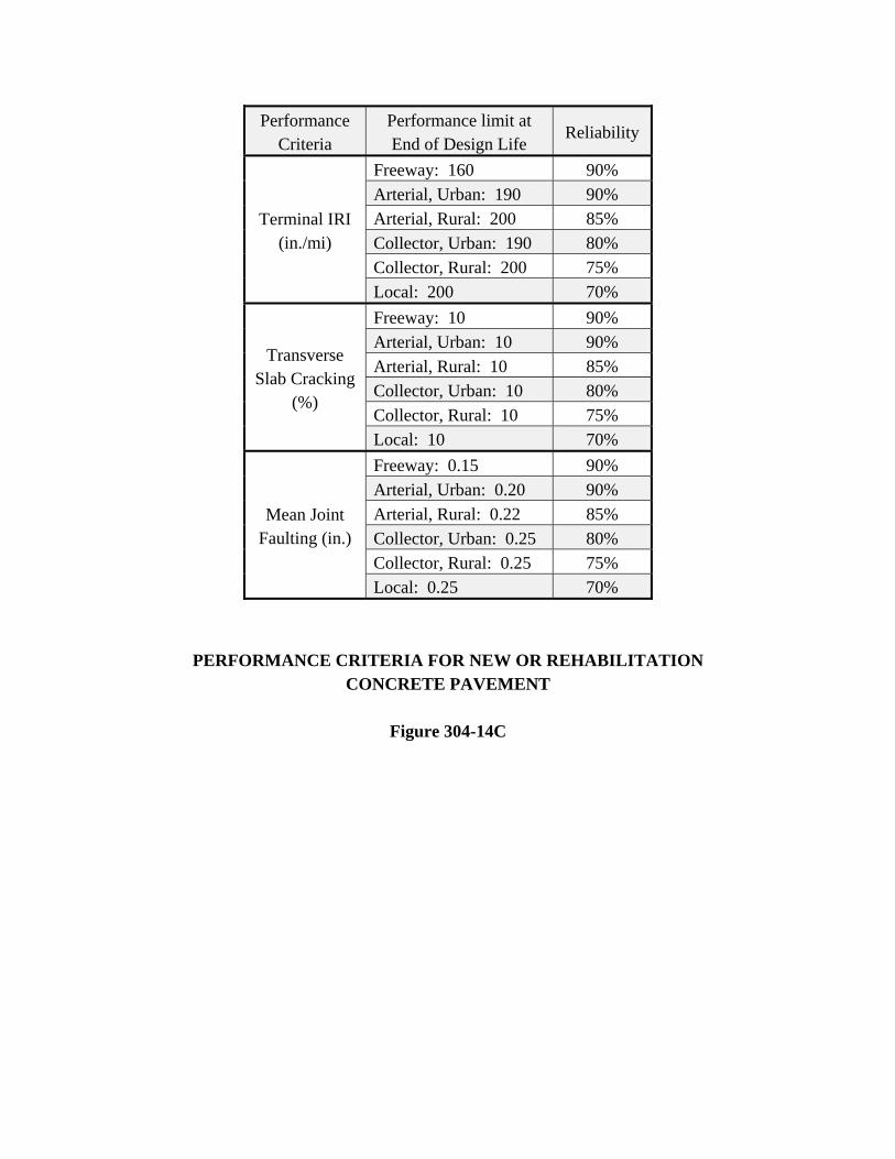
Performance Criteria
Performance limit at End of Design Life
Reliability
Terminal IRI (in./mi)
Freeway: 160 90% Arterial, Urban: 190 90% Arterial, Rural: 200 85% Collector, Urban: 190 80% Collector, Rural: 200 75% Local: 200 70%
Transverse Slab Cracking
(%)
Freeway: 10 90% Arterial, Urban: 10 90% Arterial, Rural: 10 85% Collector, Urban: 10 80% Collector, Rural: 10 75% Local: 10 70%
Mean Joint Faulting (in.)
Freeway: 0.15 90% Arterial, Urban: 0.20 90% Arterial, Rural: 0.22 85% Collector, Urban: 0.25 80% Collector, Rural: 0.25 75% Local: 0.25 70%
PERFORMANCE CRITERIA FOR NEW OR REHABILITATION CONCRETE PAVEMENT
Figure 304-14C
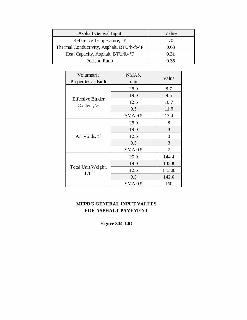
Asphalt General Input Value Reference Temperature, °F 70
Thermal Conductivity, Asphalt, BTU/h-ft-°F 0.63 Heat Capacity, Asphalt, BTU/lb-°F 0.31
Poisson Ratio 0.35
Volumetric Properties as Built
NMAS, mm
Value
Effective Binder Content, %
25.0 8.7 19.0 9.5 12.5 10.7 9.5 11.6
SMA 9.5 13.4
Air Voids, %
25.0 8 19.0 8 12.5 8 9.5 8
SMA 9.5 7
Total Unit Weight, lb/ft3
25.0 144.4 19.0 143.8 12.5 143.08 9.5 142.6
SMA 9.5 160
MEPDG GENERAL INPUT VALUES FOR ASPHALT PAVEMENT
Figure 304-14D
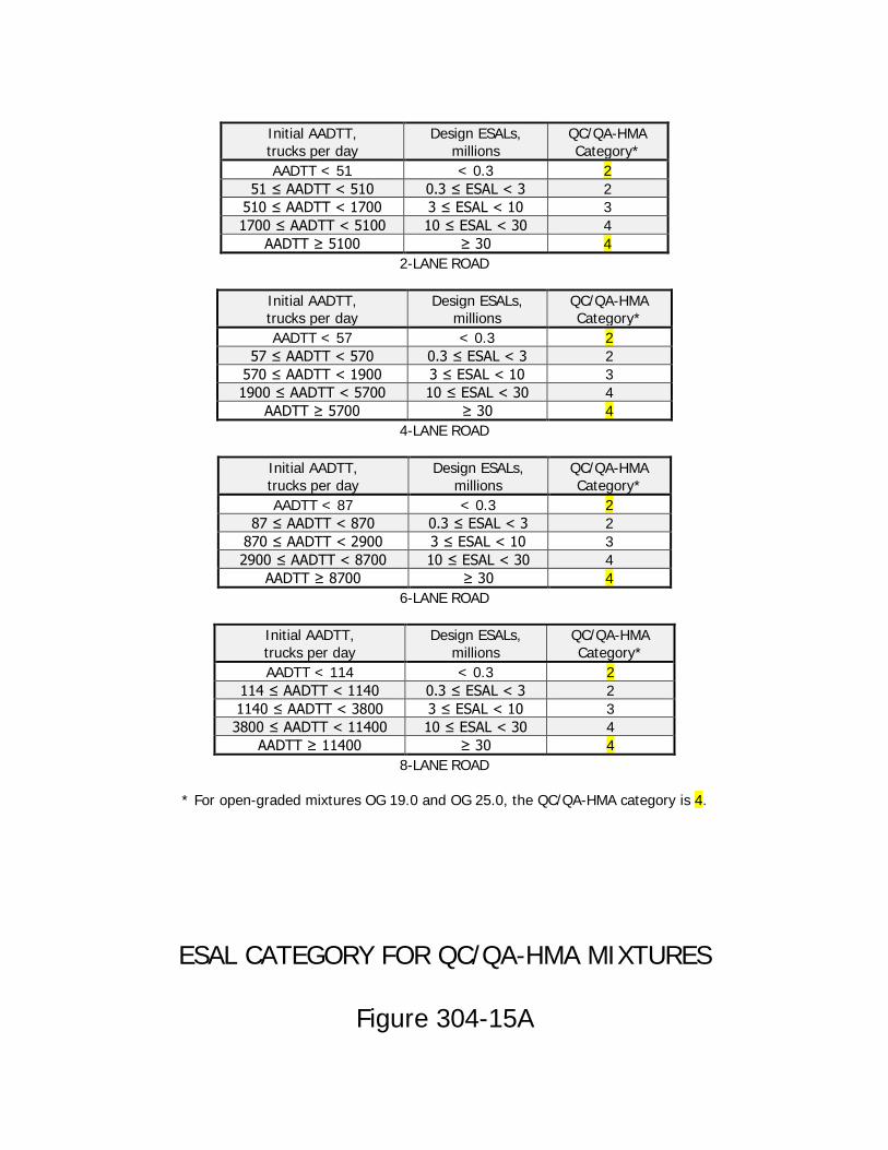
Initial AADTT, trucks per day
Design ESALs, millions
QC/QA-HMA Category*
AADTT < 51 < 0.3 2 51 ≤ AADTT < 510 0.3 ≤ ESAL < 3 2
510 ≤ AADTT < 1700 3 ≤ ESAL < 10 3 1700 ≤ AADTT < 5100 10 ≤ ESAL < 30 4
AADTT ≥ 5100 ≥ 30 4 2-LANE ROAD
Initial AADTT, trucks per day
Design ESALs, millions
QC/QA-HMA Category*
AADTT < 57 < 0.3 2 57 ≤ AADTT < 570 0.3 ≤ ESAL < 3 2
570 ≤ AADTT < 1900 3 ≤ ESAL < 10 3 1900 ≤ AADTT < 5700 10 ≤ ESAL < 30 4
AADTT ≥ 5700 ≥ 30 4 4-LANE ROAD
Initial AADTT, trucks per day
Design ESALs, millions
QC/QA-HMA Category*
AADTT < 87 < 0.3 2 87 ≤ AADTT < 870 0.3 ≤ ESAL < 3 2
870 ≤ AADTT < 2900 3 ≤ ESAL < 10 3 2900 ≤ AADTT < 8700 10 ≤ ESAL < 30 4
AADTT ≥ 8700 ≥ 30 4 6-LANE ROAD
Initial AADTT, trucks per day
Design ESALs, millions
QC/QA-HMA Category*
AADTT < 114 < 0.3 2 114 ≤ AADTT < 1140 0.3 ≤ ESAL < 3 2 1140 ≤ AADTT < 3800 3 ≤ ESAL < 10 3 3800 ≤ AADTT < 11400 10 ≤ ESAL < 30 4
AADTT ≥ 11400 ≥ 30 4 8-LANE ROAD
* For open-graded mixtures OG 19.0 and OG 25.0, the QC/QA-HMA category is 4.
ESAL CATEGORY FOR QC/QA-HMA MIXTURES
Figure 304-15A
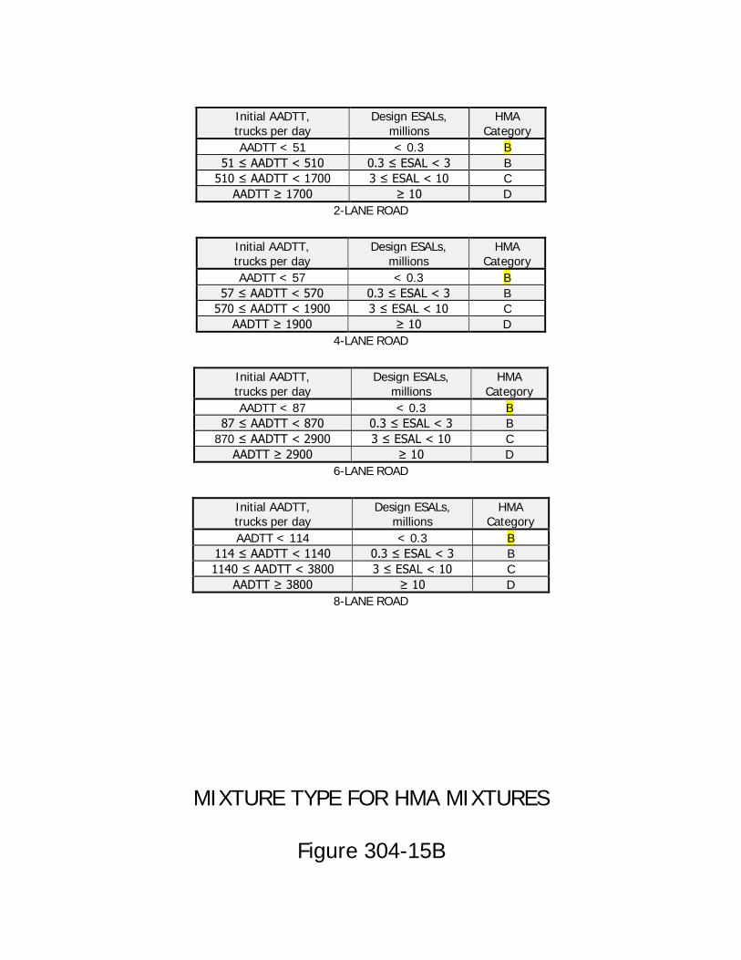
Initial AADTT, trucks per day
Design ESALs, millions
HMA Category
AADTT < 51 < 0.3 B 51 ≤ AADTT < 510 0.3 ≤ ESAL < 3 B
510 ≤ AADTT < 1700 3 ≤ ESAL < 10 C AADTT ≥ 1700 ≥ 10 D
2-LANE ROAD
Initial AADTT, trucks per day
Design ESALs, millions
HMA Category
AADTT < 57 < 0.3 B 57 ≤ AADTT < 570 0.3 ≤ ESAL < 3 B
570 ≤ AADTT < 1900 3 ≤ ESAL < 10 C AADTT ≥ 1900 ≥ 10 D
4-LANE ROAD
Initial AADTT, trucks per day
Design ESALs, millions
HMA Category
AADTT < 87 < 0.3 B 87 ≤ AADTT < 870 0.3 ≤ ESAL < 3 B
870 ≤ AADTT < 2900 3 ≤ ESAL < 10 C AADTT ≥ 2900 ≥ 10 D
6-LANE ROAD
Initial AADTT, trucks per day
Design ESALs, millions
HMA Category
AADTT < 114 < 0.3 B 114 ≤ AADTT < 1140 0.3 ≤ ESAL < 3 B 1140 ≤ AADTT < 3800 3 ≤ ESAL < 10 C
AADTT ≥ 3800 ≥ 10 D 8-LANE ROAD
MIXTURE TYPE FOR HMA MIXTURES
Figure 304-15B
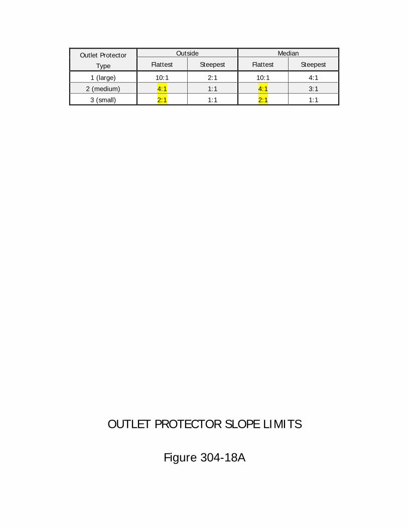
Outlet Protector
Type
Outside Median
Flattest Steepest Flattest Steepest
1 (large) 10:1 2:1 10:1 4:1
2 (medium) 4:1 1:1 4:1 3:1
3 (small) 2:1 1:1 2:1 1:1
OUTLET PROTECTOR SLOPE LIMITS
Figure 304-18A
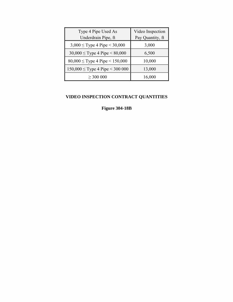
Type 4 Pipe Used As Underdrain Pipe, ft
Video Inspection Pay Quantity, ft
3,000 ≤ Type 4 Pipe < 30,000 3,000
30,000 ≤ Type 4 Pipe < 80,000 6,500
80,000 ≤ Type 4 Pipe < 150,000 10,000
150,000 ≤ Type 4 Pipe < 300 000 13,000
≥ 300 000 16,000
VIDEO INSPECTION CONTRACT QUANTITIES
Figure 304-18B
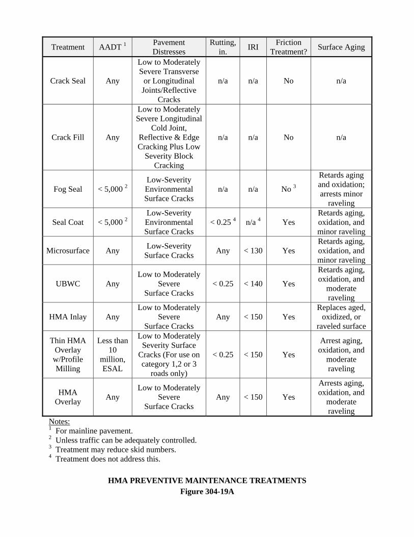
Treatment AADT 1 Pavement Distresses
Rutting,in. IRI Friction
Treatment? Surface Aging
Crack Seal Any
Low to Moderately Severe Transverse
or Longitudinal Joints/Reflective
Cracks
n/a n/a No n/a
Crack Fill Any
Low to Moderately Severe Longitudinal
Cold Joint, Reflective & Edge Cracking Plus Low
Severity Block Cracking
n/a n/a No n/a
Fog Seal < 5,000 2 Low-Severity Environmental Surface Cracks
n/a n/a No 3
Retards aging and oxidation; arrests minor
raveling
Seal Coat < 5,000 2 Low-Severity Environmental Surface Cracks
< 0.25 4 n/a 4 Yes Retards aging, oxidation, and minor raveling
Microsurface Any Low-Severity Surface Cracks Any < 130 Yes
Retards aging, oxidation, and minor raveling
UBWC Any Low to Moderately
Severe Surface Cracks
< 0.25 < 140 Yes
Retards aging, oxidation, and
moderate raveling
HMA Inlay Any Low to Moderately
Severe Surface Cracks
Any < 150 Yes Replaces aged,
oxidized, or raveled surface
Thin HMA Overlay w/Profile Milling
Less than 10
million, ESAL
Low to Moderately Severity Surface
Cracks (For use on category 1,2 or 3
roads only)
< 0.25 < 150 Yes
Arrest aging, oxidation, and
moderate raveling
HMA Overlay Any
Low to Moderately Severe
Surface Cracks Any < 150 Yes
Arrests aging, oxidation, and
moderate raveling
Notes: 1 For mainline pavement. 2 Unless traffic can be adequately controlled. 3 Treatment may reduce skid numbers. 4 Treatment does not address this.
HMA PREVENTIVE MAINTENANCE TREATMENTS Figure 304-19A
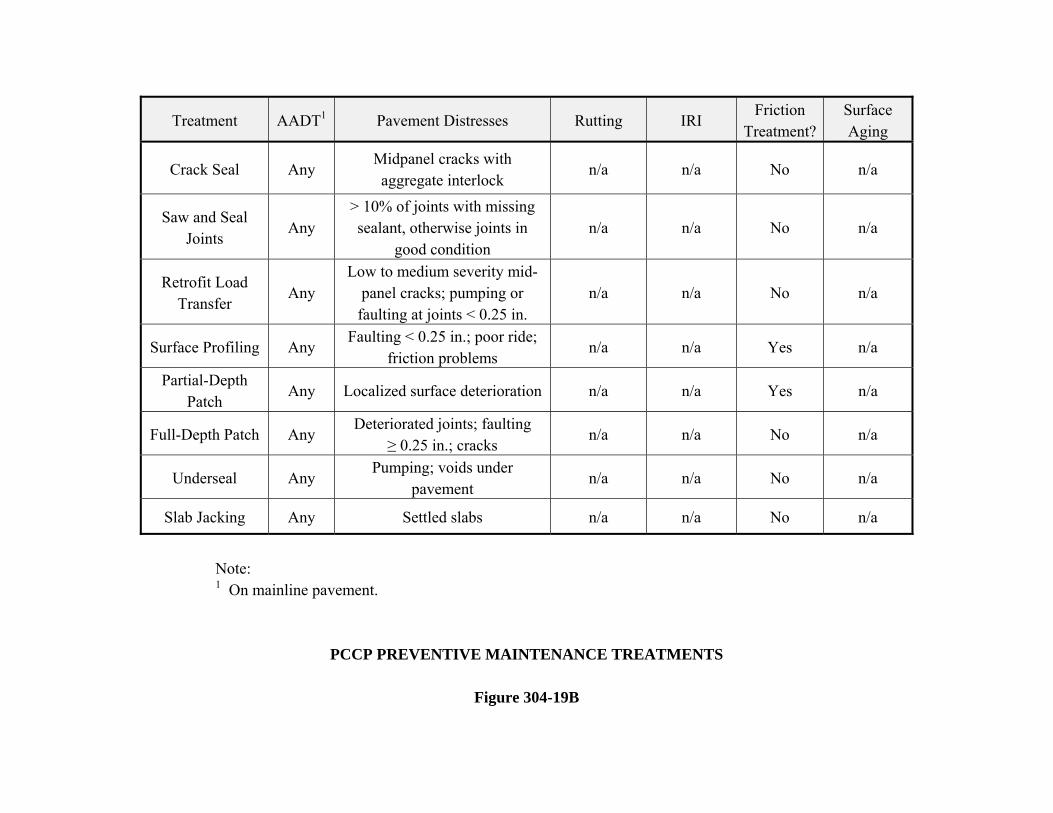
Treatment AADT1 Pavement Distresses Rutting IRI Friction
Treatment?Surface Aging
Crack Seal Any Midpanel cracks with aggregate interlock
n/a n/a No n/a
Saw and Seal Joints
Any > 10% of joints with missing sealant, otherwise joints in
good condition n/a n/a No n/a
Retrofit Load Transfer
Any Low to medium severity mid-
panel cracks; pumping or faulting at joints < 0.25 in.
n/a n/a No n/a
Surface Profiling Any Faulting < 0.25 in.; poor ride;
friction problems n/a n/a Yes n/a
Partial-Depth Patch
Any Localized surface deterioration n/a n/a Yes n/a
Full-Depth Patch Any Deteriorated joints; faulting
≥ 0.25 in.; cracks n/a n/a No n/a
Underseal Any Pumping; voids under
pavement n/a n/a No n/a
Slab Jacking Any Settled slabs n/a n/a No n/a
Note: 1 On mainline pavement.
PCCP PREVENTIVE MAINTENANCE TREATMENTS
Figure 304-19B
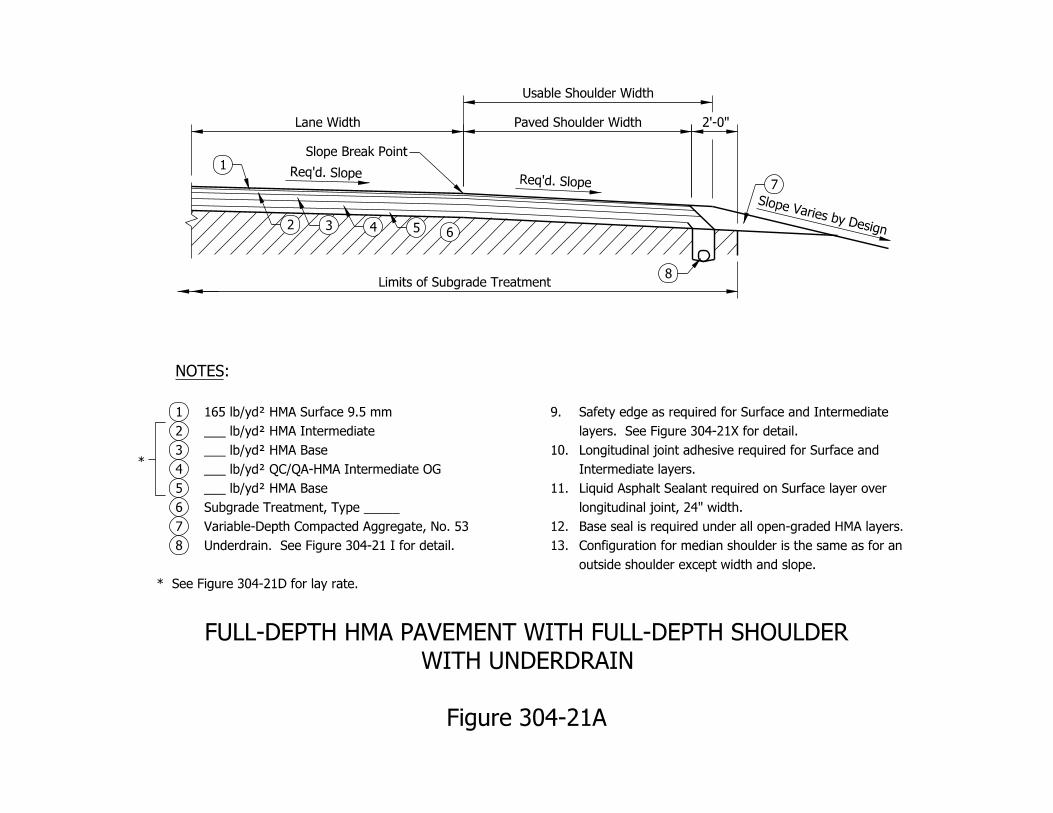
Limits of Subgrade Treatment
Paved Shoulder WidthLane Width
Usable Shoulder Width
Req’d. SlopeReq’d. Slope
6
Slope Break Point
1
2 3 4 5
7
8
Slope Varies by Design
* See Figure 304-21D for lay rate.
Underdrain. See Figure 304-21 I for detail.8
Variable-Depth Compacted Aggregate, No. 537
Subgrade Treatment, Type _____6
___ lb/yd† HMA Base5
___ lb/yd† QC/QA-HMA Intermediate OG4
___ lb/yd† HMA Base3
___ lb/yd† HMA Intermediate2
165 lb/yd† HMA Surface 9.5 mm1
:NOTES
*
outside shoulder except width and slope.
Configuration for median shoulder is the same as for an 13.
Base seal is required under all open-graded HMA layers.12.
longitudinal joint, 24" width.
Liquid Asphalt Sealant required on Surface layer over 11.
Intermediate layers.
Longitudinal joint adhesive required for Surface and 10.
layers. See Figure 304-21X for detail.
Safety edge as required for Surface and Intermediate 9.
Figure 304-21A
WITH UNDERDRAIN
FULL-DEPTH HMA PAVEMENT WITH FULL-DEPTH SHOULDER
2’-0"
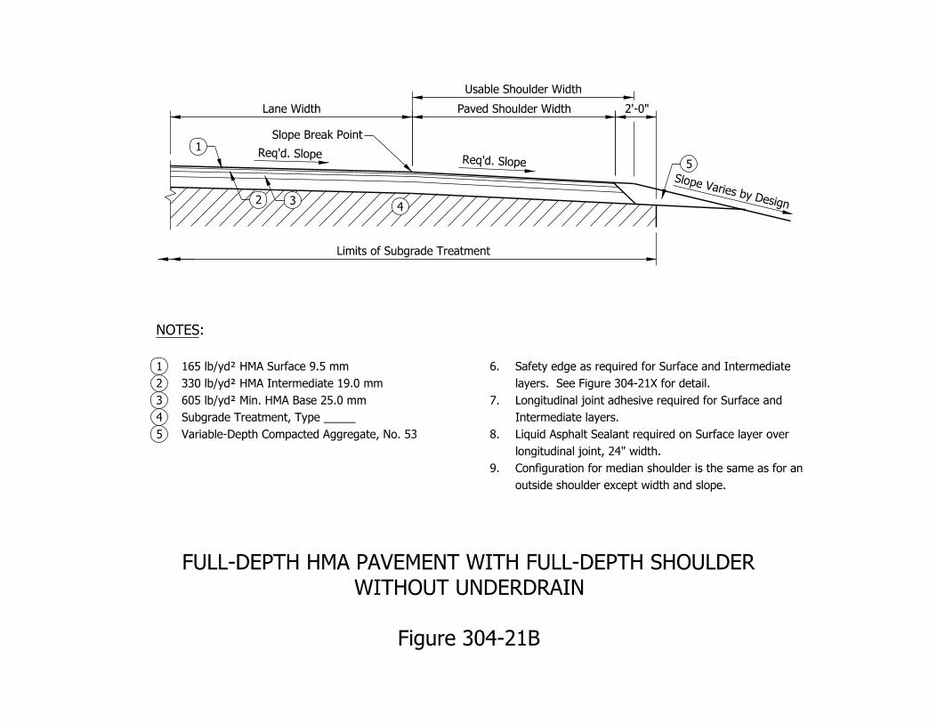
Limits of Subgrade Treatment
Paved Shoulder WidthLane Width
Usable Shoulder Width
Req’d. SlopeReq’d. Slope
4
Slope Break Point
1
2 3
5
Slope Varies by Design
Variable-Depth Compacted Aggregate, No. 535
Subgrade Treatment, Type _____4
605 lb/yd† Min. HMA Base 25.0 mm3
330 lb/yd† HMA Intermediate 19.0 mm2
165 lb/yd† HMA Surface 9.5 mm1
:NOTES
outside shoulder except width and slope.
Configuration for median shoulder is the same as for an 9.
longitudinal joint, 24" width.
Liquid Asphalt Sealant required on Surface layer over 8.
Intermediate layers.
Longitudinal joint adhesive required for Surface and 7.
layers. See Figure 304-21X for detail.
Safety edge as required for Surface and Intermediate 6.
Figure 304-21B
WITHOUT UNDERDRAIN
FULL-DEPTH HMA PAVEMENT WITH FULL-DEPTH SHOULDER
2’-0"
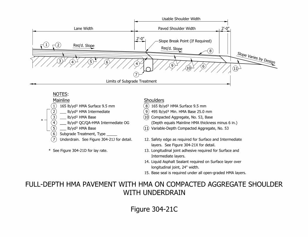
Req’d. SlopeReq’d. Slope
Slope Varies by Design6
6
7
Lane Width
Usable Shoulder Width
Paved Shoulder Width
Limits of Subgrade Treatment
2’-0"Slope Break Point (If Required)
1 2
3 4 54
910
8
11
* See Figure 304-21D for lay rate.
Underdrain. See Figure 304-21J for detail.7
Subgrade Treatment, Type _____6
___ lb/yd† HMA Base5
___ lb/yd† QC/QA-HMA Intermediate OG4
___ lb/yd† HMA Base3
___ lb/yd† HMA Intermediate2
165 lb/yd† HMA Surface 9.5 mm1
Mainline
:NOTES
*
Base seal is required under all open-graded HMA layers.15.
longitudinal joint, 24" width.
Liquid Asphalt Sealant required on Surface layer over 14.
Intermediate layers.
Longitudinal joint adhesive required for Surface and 13.
layers. See Figure 304-21X for detail.
Safety edge as required for Surface and Intermediate 12.
Variable-Depth Compacted Aggregate, No. 5311
(Depth equals Mainline HMA thickness minus 6 in.)
Compacted Aggregate, No. 53, Base10
495 lb/yd† Min. HMA Base 25.0 mm 9
165 lb/yd† HMA Surface 9.5 mm 8
Shoulders
Figure 304-21C
WITH UNDERDRAIN
FULL-DEPTH HMA PAVEMENT WITH HMA ON COMPACTED AGGREGATE SHOULDER
2’-0"
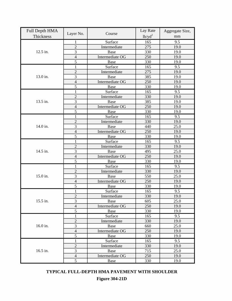
Full Depth HMA Thickness
Layer No. CourseLay Rate
lb/yd2Aggregate Size,
mm1 Surface 165 9.52 Intermediate 275 19.03 Base 330 19.04 Intermediate OG 250 19.05 Base 330 19.01 Surface 165 9.52 Intermediate 275 19.03 Base 385 19.04 Intermediate OG 250 19.05 Base 330 19.01 Surface 165 9.52 Intermediate 330 19.03 Base 385 19.04 Intermediate OG 250 19.05 Base 330 19.01 Surface 165 9.52 Intermediate 330 19.03 Base 440 25.04 Intermediate OG 250 19.05 Base 330 19.01 Surface 165 9.52 Intermediate 330 19.03 Base 495 25.04 Intermediate OG 250 19.05 Base 330 19.01 Surface 165 9.52 Intermediate 330 19.03 Base 550 25.04 Intermediate OG 250 19.05 Base 330 19.01 Surface 165 9.52 Intermediate 330 19.03 Base 605 25.04 Intermediate OG 250 19.05 Base 330 19.01 Surface 165 9.52 Intermediate 330 19.03 Base 660 25.04 Intermediate OG 250 19.05 Base 330 19.01 Surface 165 9.52 Intermediate 330 19.03 Base 715 25.04 Intermediate OG 250 19.05 Base 330 19.0
TYPICAL FULL-DEPTH HMA PAVEMENT WITH SHOULDERFigure 304-21D
15.0 in.
15.5 in.
16.0 in.
16.5 in.
14.0 in.
12.5 in.
13.0 in.
13.5 in.
14.5 in.
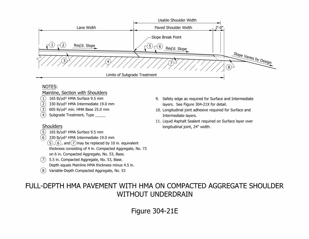
Lane Width
Usable Shoulder Width
Paved Shoulder Width
Limits of Subgrade Treatment
Variable-Depth Compacted Aggregate, No. 538
Depth equals Mainline HMA thickness minus 4.5 in.
5.5 in. Compacted Aggregate, No. 53, Base.7
on 6 in. Compacted Aggregate, No. 53, Base.
thickness consisting of 4 in. Compacted Aggregate, No. 73
5 , 6 , and 7 may be replaced by 10 in. equivalent
330 lb/yd† HMA Intermediate 19.0 mm6
165 lb/yd† HMA Surface 9.5 mm5
Shoulders
Subgrade Treatment, Type _____4
605 lb/yd† min. HMA Base 25.0 mm3
330 lb/yd† HMA Intermediate 19.0 mm2
165 lb/yd† HMA Surface 9.5 mm1
Mainline, Section with Shoulders
:NOTES
longitudinal joint, 24" width.
Liquid Asphalt Sealant required on Surface layer over 11.
Intermediate layers.
Longitudinal joint adhesive required for Surface and 10.
layers. See Figure 304-21X for detail.
Safety edge as required for Surface and Intermediate 9.
Figure 304-21E
WITHOUT UNDERDRAIN
FULL-DEPTH HMA PAVEMENT WITH HMA ON COMPACTED AGGREGATE SHOULDER
2’-0"
Slope Varies by Design
Req’d. SlopeReq’d. Slope1 2
3 4
5
Slope Break Point
7
8
6
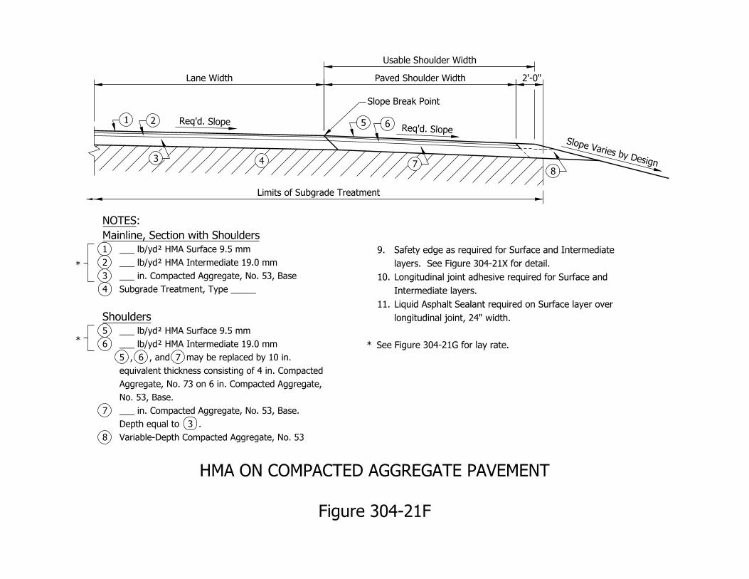
Lane Width
Usable Shoulder Width
Paved Shoulder Width
Limits of Subgrade Treatment
Variable-Depth Compacted Aggregate, No. 538
Depth equal to 3 .
___ in. Compacted Aggregate, No. 53, Base.7
No. 53, Base.
Aggregate, No. 73 on 6 in. Compacted Aggregate,
equivalent thickness consisting of 4 in. Compacted
5 , 6 , and 7 may be replaced by 10 in.
___ lb/yd† HMA Intermediate 19.0 mm6
___ lb/yd† HMA Surface 9.5 mm5
Shoulders
Subgrade Treatment, Type _____4
___ in. Compacted Aggregate, No. 53, Base3
___ lb/yd† HMA Intermediate 19.0 mm2
___ lb/yd† HMA Surface 9.5 mm1
Mainline, Section with Shoulders
:NOTES
See Figure 304-21G for lay rate. *
longitudinal joint, 24" width.
Liquid Asphalt Sealant required on Surface layer over 11.
Intermediate layers.
Longitudinal joint adhesive required for Surface and 10.
layers. See Figure 304-21X for detail.
Safety edge as required for Surface and Intermediate 9.
Figure 304-21F
HMA ON COMPACTED AGGREGATE PAVEMENT
2’-0"
*
*
Slope Varies by Design
Req’d. SlopeReq’d. Slope1 2
3 4
5
Slope Break Point
78
6
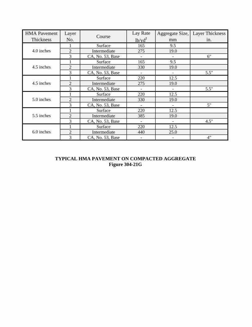
HMA Pavement Thickness
Layer No. Course
Lay Rate lb/yd2
Aggregate Size, mm
Layer Thickness in.
1 Surface 165 9.52 Intermediate 275 19.03 CA, No. 53, Base - - 6"1 Surface 165 9.52 Intermediate 330 19.03 CA, No. 53, Base - - 5.5"1 Surface 220 12.52 Intermediate 275 19.03 CA, No. 53, Base - - 5.5"1 Surface 220 12.52 Intermediate 330 19.03 CA, No. 53, Base - - 5"1 Surface 220 12.52 Intermediate 385 19.03 CA, No. 53, Base - - 4.5"1 Surface 220 12.52 Intermediate 440 25.03 CA, No. 53, Base - - 4"
4.5 inches
5.0 inches
5.5 inches
TYPICAL HMA PAVEMENT ON COMPACTED AGGREGATEFigure 304-21G
4.0 inches
6.0 inches
4.5 inches
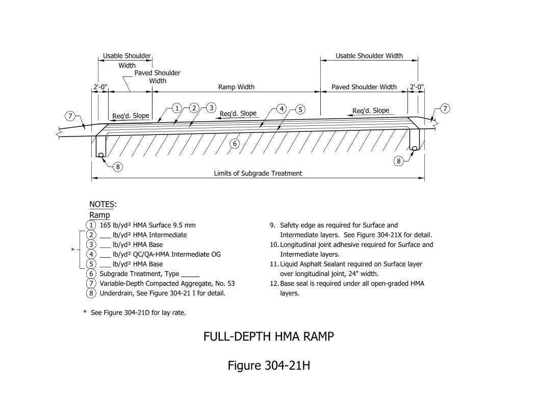
Width
Usable Shoulder
Limits of Subgrade Treatment
Usable Shoulder Width
Req’d. SlopeReq’d. SlopeReq’d. Slope
7
88
7
1 2 3 4 5
6
*
* See Figure 304-21D for lay rate.
Underdrain, See Figure 304-21 I for detail.8
Variable-Depth Compacted Aggregate, No. 537
Subgrade Treatment, Type _____6
___ lb/yd† HMA Base5
___ lb/yd† QC/QA-HMA Intermediate OG4
___ lb/yd† HMA Base3
___ lb/yd† HMA Intermediate2
165 lb/yd† HMA Surface 9.5 mm1
Ramp
:NOTES
layers.
Base seal is required under all open-graded HMA 12.
over longitudinal joint, 24" width.
Liquid Asphalt Sealant required on Surface layer 11.
Intermediate layers.
Longitudinal joint adhesive required for Surface and 10.
Intermediate layers. See Figure 304-21X for detail.
Safety edge as required for Surface and 9.
Figure 304-21H
FULL-DEPTH HMA RAMP
2’-0" 2’-0"
Paved Shoulder Width
Ramp Width
Width
Paved Shoulder
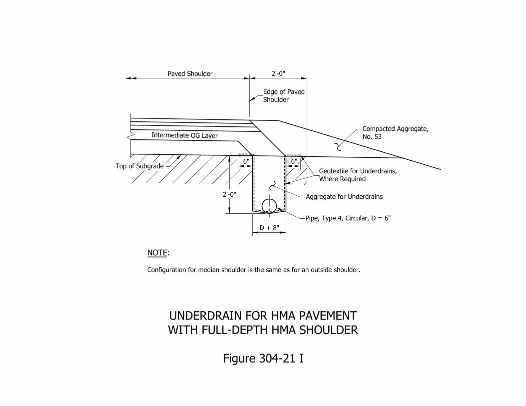
Shoulder
Edge of Paved
Aggregate for Underdrains
Pipe, Type 4, Circular, D = 6"
Top of Subgrade
Paved Shoulder
D + 8"
Intermediate OG Layer
NOTE:
Configuration for median shoulder is the same as for an outside shoulder.
2’-0"
Where Required
Geotextile for Underdrains,
No. 53
Compacted Aggregate,
Figure 304-21 I
WITH FULL-DEPTH HMA SHOULDER
UNDERDRAIN FOR HMA PAVEMENT
2’-0"
6"6"
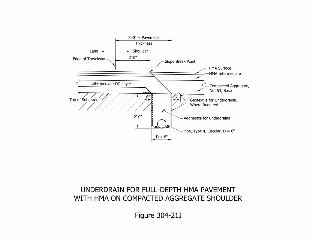
Aggregate for Underdrains
Pipe, Type 4, Circular, D = 6"
Top of Subgrade
D + 8"
Intermediate OG Layer
Slope Break PointEdge of Travelway 2’-0"
Thickness
2’-0" + Pavement
HMA Surface
HMA Intermediate
ShoulderLane
Where Required
Geotextile for Underdrains,
No. 53, Base
Compacted Aggregate,
Figure 304-21J
WITH HMA ON COMPACTED AGGREGATE SHOULDER
UNDERDRAIN FOR FULL-DEPTH HMA PAVEMENT
2’-0"
6"6"
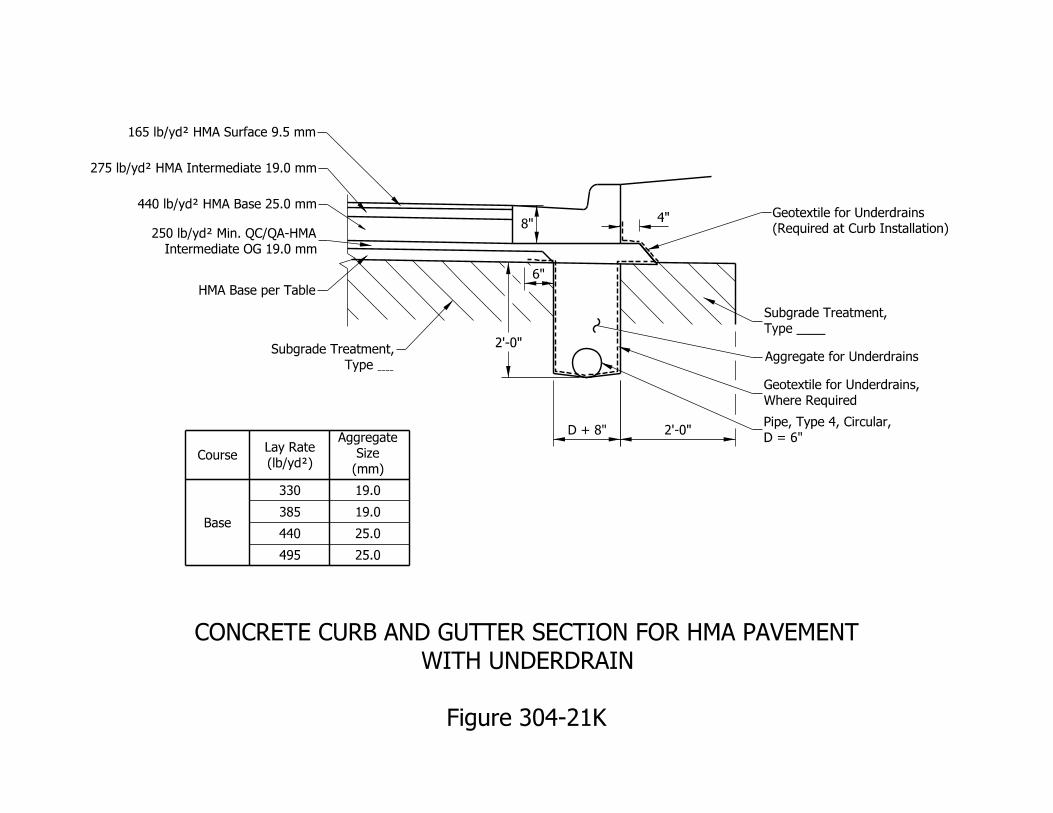
HMA Base per Table
(Required at Curb Installation)
Geotextile for Underdrains
Type ____
Subgrade Treatment,
2’-0"D + 8"
4"
Figure 304-21K
WITH UNDERDRAIN
CONCRETE CURB AND GUTTER SECTION FOR HMA PAVEMENT
2’-0"
6"
8"
440 lb/yd† HMA Base 25.0 mm
Intermediate OG 19.0 mm
250 lb/yd† Min. QC/QA-HMA
275 lb/yd† HMA Intermediate 19.0 mm
165 lb/yd† HMA Surface 9.5 mm
Type
Subgrade Treatment,Aggregate for Underdrains
Where Required
Geotextile for Underdrains,
Course
330
(mm)
Size
Aggregate
19.0
19.0
25.0
25.0
Base385
440
495
D = 6"
Pipe, Type 4, Circular,
(lb/yd†)
Lay Rate
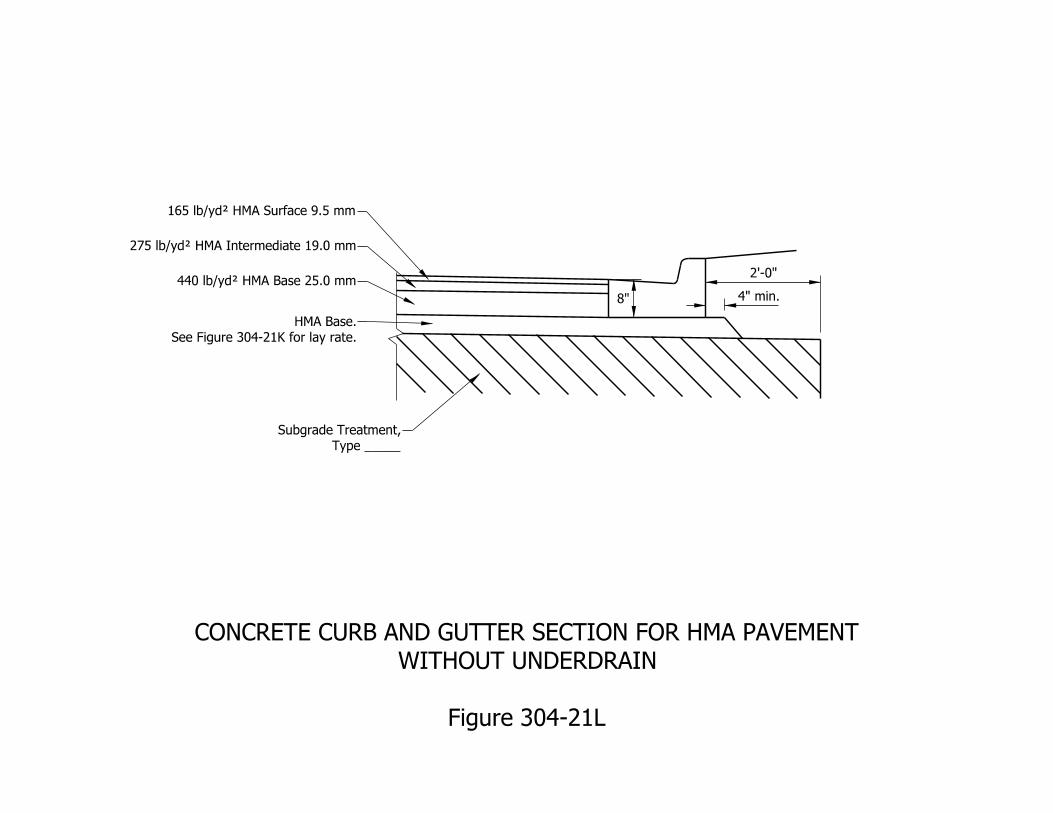
4" min.
2’-0"
8"
165 lb/yd† HMA Surface 9.5 mm
275 lb/yd† HMA Intermediate 19.0 mm
440 lb/yd† HMA Base 25.0 mm
See Figure 304-21K for lay rate.
HMA Base.
Type _____
Subgrade Treatment,
Figure 304-21L
WITHOUT UNDERDRAIN
CONCRETE CURB AND GUTTER SECTION FOR HMA PAVEMENT
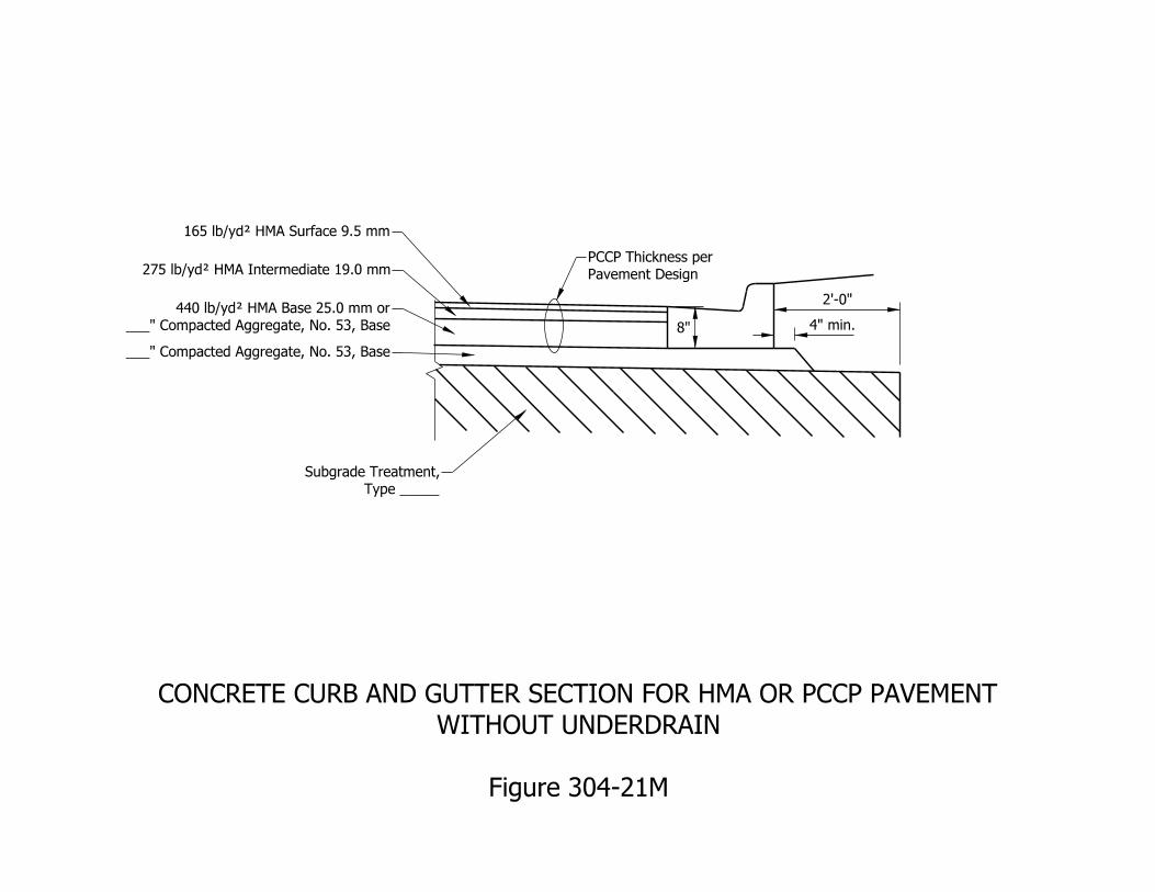
4" min.
2’-0"
8"
165 lb/yd† HMA Surface 9.5 mm
275 lb/yd† HMA Intermediate 19.0 mm
Type _____
Subgrade Treatment,
___" Compacted Aggregate, No. 53, Base
___" Compacted Aggregate, No. 53, Base
440 lb/yd† HMA Base 25.0 mm or
Pavement Design
PCCP Thickness per
Figure 304-21M
WITHOUT UNDERDRAIN
CONCRETE CURB AND GUTTER SECTION FOR HMA OR PCCP PAVEMENT
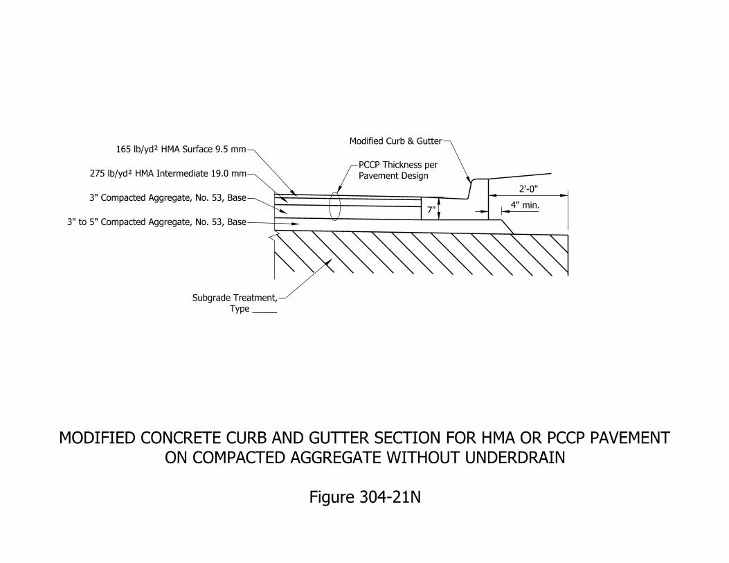
4" min.
2’-0"
7"
165 lb/yd† HMA Surface 9.5 mm
275 lb/yd† HMA Intermediate 19.0 mm
Type _____
Subgrade Treatment,
Modified Curb & Gutter
3" Compacted Aggregate, No. 53, Base
3" to 5" Compacted Aggregate, No. 53, Base
Pavement Design
PCCP Thickness per
Figure 304-21N
ON COMPACTED AGGREGATE WITHOUT UNDERDRAIN
MODIFIED CONCRETE CURB AND GUTTER SECTION FOR HMA OR PCCP PAVEMENT
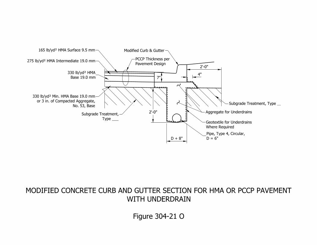
D + 8"
4"
Modified Curb & Gutter
No. 53, Base
or 3 in. of Compacted Aggregate,
330 lb/yd† Min. HMA Base 19.0 mm
Figure 304-21 O
WITH UNDERDRAIN
MODIFIED CONCRETE CURB AND GUTTER SECTION FOR HMA OR PCCP PAVEMENT
2’-0"
7"
Aggregate for Underdrains
275 lb/yd† HMA Intermediate 19.0 mm
165 lb/yd† HMA Surface 9.5 mm
Type ___
Subgrade Treatment,
D = 6"
Pipe, Type 4, Circular,
2’-0"
Subgrade Treatment, Type
Base 19.0 mm
330 lb/yd† HMA
Where Required
Geotextile for Underdrains
Pavement Design
PCCP Thickness per
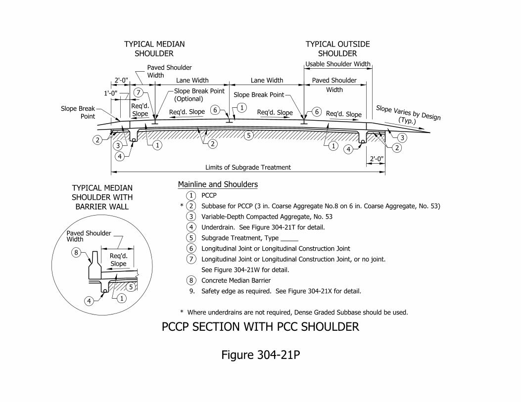
Slope
Req’d.
SHOULDER
TYPICAL MEDIAN
SHOULDER
TYPICAL OUTSIDE
BARRIER WALL
SHOULDER WITH
TYPICAL MEDIAN
5
8
41
WidthPaved Shoulder
Req’d. Slope Req’d. Slope Req’d. Slope
4
7
6 6
3
43 1
1
2
Slope
Req’d.
(Typ.)
Slope Varies by Design
2’-0"
Usable Shoulder Width
Width
Paved Shoulder
Lane Width
Lane Width
1’-0"
2’-0"
5
Limits of Subgrade Treatment
Point
Slope Break
(Optional)
Slope Break Point Slope Break Point
Width
Paved Shoulder
21 2
Where underdrains are not required, Dense Graded Subbase should be used. *
Safety edge as required. See Figure 304-21X for detail. 9.
Concrete Median Barrier 8
See Figure 304-21W for detail.
Longitudinal Joint or Longitudinal Construction Joint, or no joint. 7
Longitudinal Joint or Longitudinal Construction Joint 6
Subgrade Treatment, Type _____ 5
Underdrain. See Figure 304-21T for detail. 4
Variable-Depth Compacted Aggregate, No. 53 3
Subbase for PCCP (3 in. Coarse Aggregate No.8 on 6 in. Coarse Aggregate, No. 53) 2 *
PCCP 1
Mainline and Shoulders
Figure 304-21P
PCCP SECTION WITH PCC SHOULDER
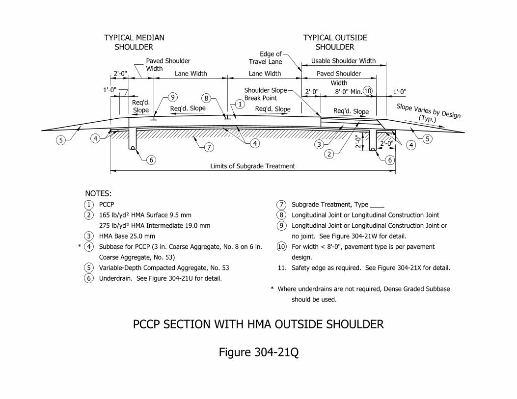
10
SHOULDER
TYPICAL MEDIAN
SHOULDER
TYPICAL OUTSIDE
Req’d. Slope Req’d. Slope Req’d. Slope
9 8
5
1Slope
Req’d.
(Typ.)
Slope Varies by Design
2’-0"
Usable Shoulder Width
Width
Paved Shoulder
Lane Width
Lane Width
2’-0"
Limits of Subgrade Treatment
2’-0"
6
7
6
45
2
Width
Paved Shoulder
3 4
1’-0"
Underdrain. See Figure 304-21U for detail. 6
Variable-Depth Compacted Aggregate, No. 53 5
Coarse Aggregate, No. 53)
Subbase for PCCP (3 in. Coarse Aggregate, No. 8 on 6 in. 4 *
HMA Base 25.0 mm 3
275 lb/yd† HMA Intermediate 19.0 mm
165 lb/yd† HMA Surface 9.5 mm 2
PCCP 1
:NOTES
should be used.
Where underdrains are not required, Dense Graded Subbase *
Safety edge as required. See Figure 304-21X for detail.11.
design.
For width < 8’-0", pavement type is per pavement 10
no joint. See Figure 304-21W for detail.
Longitudinal Joint or Longitudinal Construction Joint or 9
Longitudinal Joint or Longitudinal Construction Joint 8
Subgrade Treatment, Type ____ 7
Figure 304-21Q
PCCP SECTION WITH HMA OUTSIDE SHOULDER
2’-0"
Break Point
Shoulder Slope 1’-0"
4
Travel Lane
Edge of
8’-0" Min.
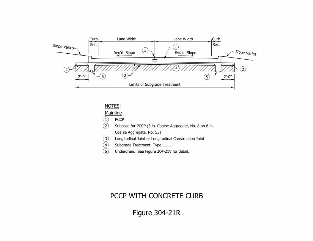
Lane Width Lane Width
Sec.
Curb
Sec.
Curb
Req’d. SlopeReq’d. Slope
2’-0" 2’-0"
Limits of Subgrade Treatment
5
3
52
1
4
Slope VariesSlope Varies
Underdrain. See Figure 304-21V for detail.5
Subgrade Treatment, Type ____4
Longitudinal Joint or Longitudinal Construction Joint3
Coarse Aggregate, No. 53)
Subbase for PCCP (3 in. Coarse Aggregate, No. 8 on 6 in. 2
PCCP1
Mainline
:NOTES
2 2
Figure 304-21R
PCCP WITH CONCRETE CURB
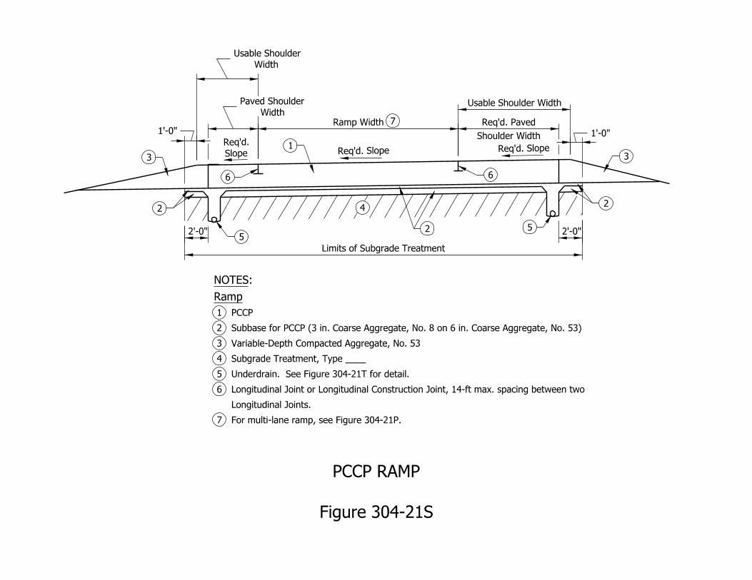
Width
Usable Shoulder
Shoulder Width
Req’d. PavedRamp Width
Usable Shoulder Width
Limits of Subgrade Treatment
Width
Paved Shoulder
For multi-lane ramp, see Figure 304-21P. 7
Longitudinal Joints.
Longitudinal Joint or Longitudinal Construction Joint, 14-ft max. spacing between two 6
Underdrain. See Figure 304-21T for detail. 5
Subgrade Treatment, Type ____ 4
Variable-Depth Compacted Aggregate, No. 53 3
Subbase for PCCP (3 in. Coarse Aggregate, No. 8 on 6 in. Coarse Aggregate, No. 53) 2
PCCP 1
Ramp
:NOTES
Figure 304-21S
PCCP RAMP
1’-0"
Slope
Req’d.Req’d. Slope Req’d. Slope
3
1
6
5
6
5
3
2
4
7
22
2’-0" 2’-0"
1’-0"
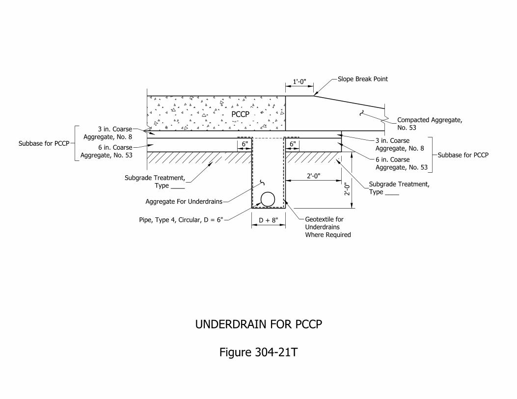
Type ____
Subgrade Treatment,
Pipe, Type 4, Circular, D = 6"
Aggregate For Underdrains
No. 53
Compacted Aggregate,
2’-0"
D + 8"
2’-0"
1’-0"Slope Break Point
PCCP
Subbase for PCCP
Subbase for PCCPAggregate, No. 8
3 in. Coarse
Aggregate, No. 53
6 in. Coarse
Figure 304-21T
UNDERDRAIN FOR PCCP
6"
Type ____
Subgrade Treatment,
Where Required
Underdrains
Geotextile for
6"
Aggregate, No. 8
3 in. Coarse
Aggregate, No. 53
6 in. Coarse
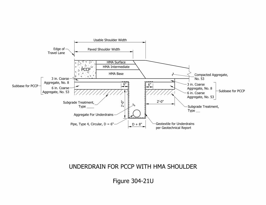
Type ____
Subgrade Treatment,
Pipe, Type 4, Circular, D = 6"
No. 53
Compacted Aggregate,
2’-0"
D + 8"
6"
PCCP
HMA Surface
HMA Intermediate
HMA Base
6"
Type
Subgrade Treatment,
Aggregate, No. 8
3 in. Coarse
Aggregate, No. 53
6 in. Coarse Subbase for PCCP
Aggregate, No. 8
3 in. Coarse
Aggregate, No. 53
6 in. CoarseSubbase for PCCP
Figure 304-21U
UNDERDRAIN FOR PCCP WITH HMA SHOULDER
Paved Shoulder Width
Usable Shoulder Width
Travel Lane
Edge of
Aggregate For Underdrains
per Geotechnical Report
Geotextile for Underdrains 2’-0"
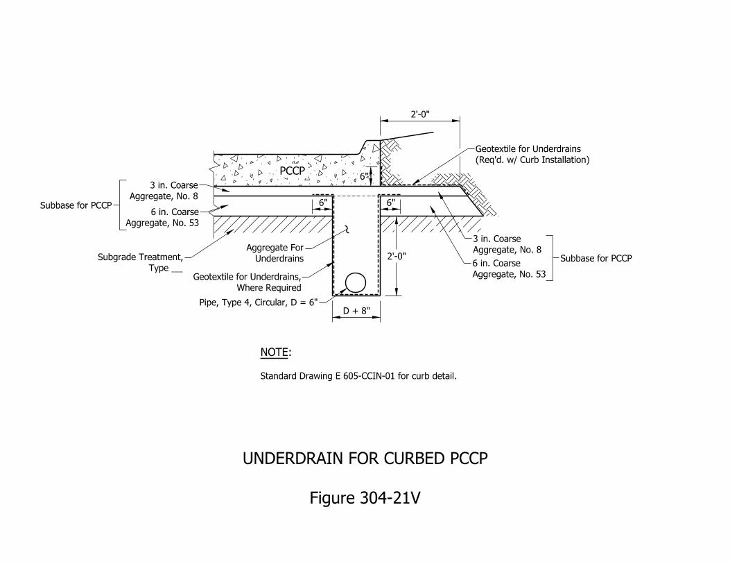
2’-0"
Pipe, Type 4, Circular, D = 6"D + 8"
Where Required
Geotextile for Underdrains,
Underdrains
Aggregate For
(Req’d. w/ Curb Installation)
Geotextile for Underdrains
Type
Subgrade Treatment,
PCCP
Standard Drawing E 605-CCIN-01 for curb detail.
:NOTE
6"
Aggregate, No. 8
3 in. Coarse
Aggregate, No. 8
3 in. Coarse
Aggregate, No. 53
6 in. Coarse
Aggregate, No. 53
6 in. Coarse
Figure 304-21V
UNDERDRAIN FOR CURBED PCCP
6"
Subbase for PCCP
Subbase for PCCP
2’-0"
6"
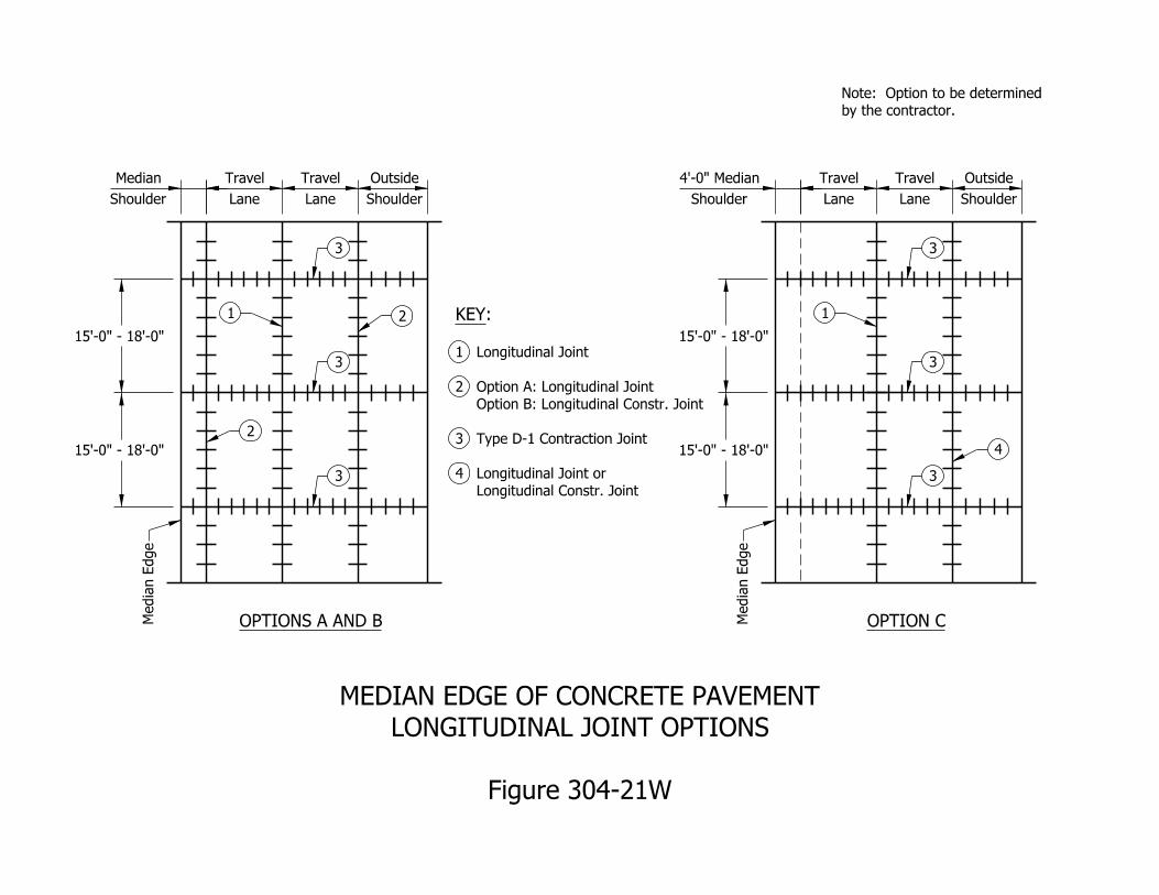
by the contractor.
Note: Option to be determined
OPTIONS A AND B OPTION C
Shoulder
Median
Shoulder
4’-0" Median
15’-0" - 18’-0"
15’-0" - 18’-0"
Lane
Travel
Lane
Travel
Shoulder
Outside
Lane
Travel
Lane
Travel
Shoulder
Outside
15’-0" - 18’-0"
15’-0" - 18’-0"
Media
n E
dge
2
1
3
3
3
2
Media
n E
dge
1
3
3
3
4
KEY:
1 Longitudinal Joint
2 Option A: Longitudinal Joint
Option B: Longitudinal Constr. Joint
3 Type D-1 Contraction Joint
4 Longitudinal Joint or
Longitudinal Constr. Joint
Figure 304-21W
LONGITUDINAL JOINT OPTIONS
MEDIAN EDGE OF CONCRETE PAVEMENT
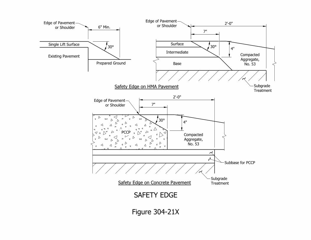
Treatment
Subgrade
Treatment
Subgrade
Subbase for PCCP
No. 53
Aggregate,
Compacted
No. 53
Aggregate,
Compacted
Single Lift Surface
Existing Pavement
Prepared Ground
Safety Edge on HMA Pavement
Surface
Intermediate
Base
PCCP
Safety Edge on Concrete Pavement
7"
2’-0"
2’-0"
or Shoulder
Edge of Pavement
6" Min.
30°
or Shoulder
Edge of Pavement
7"
30°
or Shoulder
Edge of Pavement
30°
Figure 304-21X
SAFETY EDGE
4"
4"
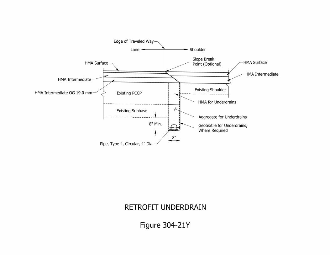
Existing ShoulderExisting PCCP
Existing Subbase
ShoulderLane
HMA Surface
8"
8" Min.
HMA Intermediate
Point (Optional)
Slope Break
HMA Intermediate
HMA for Underdrains
Where Required
Geotextile for Underdrains,
Pipe, Type 4, Circular, 4" Dia.
Aggregate for Underdrains
HMA Intermediate OG 19.0 mm
HMA Surface
Edge of Traveled Way
Figure 304-21Y
RETROFIT UNDERDRAIN
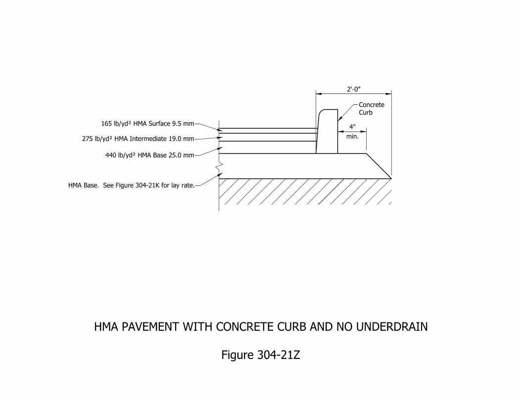
2’-0"
min.
4"165 lb/yd† HMA Surface 9.5 mm
275 lb/yd† HMA Intermediate 19.0 mm
440 lb/yd† HMA Base 25.0 mm
HMA Base. See Figure 304-21K for lay rate.
Curb
Concrete
Figure 304-21Z
HMA PAVEMENT WITH CONCRETE CURB AND NO UNDERDRAIN
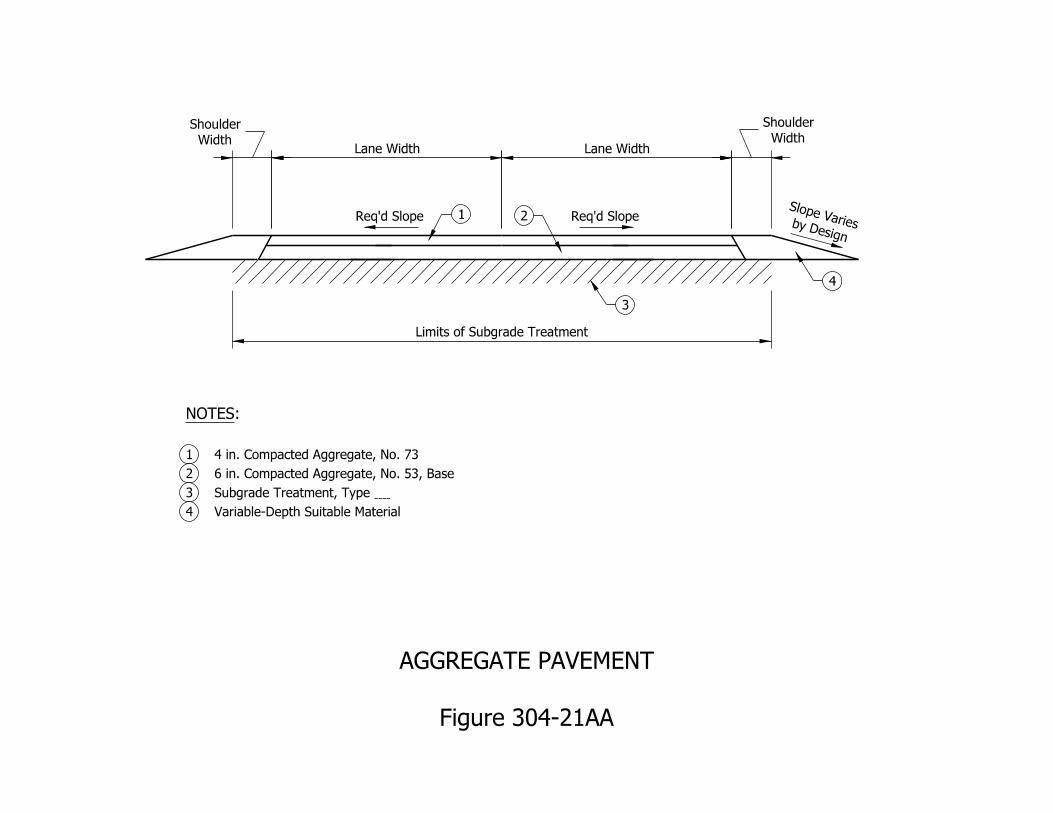
Lane Width Lane Width
Limits of Subgrade Treatment
by Design
Slope Varies Req’d SlopeReq’d Slope 1 2
3
4
Width
Shoulder
Width
Shoulder
Variable-Depth Suitable Material4
Subgrade Treatment, Type 3
6 in. Compacted Aggregate, No. 53, Base2
4 in. Compacted Aggregate, No. 731
:NOTES
Figure 304-21AA
AGGREGATE PAVEMENT
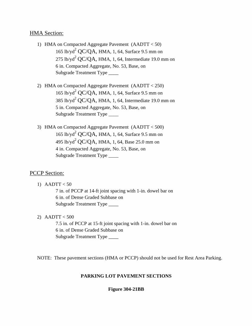
HMA Section:
1) HMA on Compacted Aggregate Pavement (AADTT < 50) 165 lb/yd2 QC/QA, HMA, 1, 64, Surface 9.5 mm on 275 lb/yd2 QC/QA, HMA, 1, 64, Intermediate 19.0 mm on 6 in. Compacted Aggregate, No. 53, Base, on Subgrade Treatment Type ____
2) HMA on Compacted Aggregate Pavement (AADTT < 250) 165 lb/yd2 QC/QA, HMA, 1, 64, Surface 9.5 mm on 385 lb/yd2 QC/QA, HMA, 1, 64, Intermediate 19.0 mm on 5 in. Compacted Aggregate, No. 53, Base, on Subgrade Treatment Type ____
3) HMA on Compacted Aggregate Pavement (AADTT < 500) 165 lb/yd2 QC/QA, HMA, 1, 64, Surface 9.5 mm on 495 lb/yd2 QC/QA, HMA, 1, 64, Base 25.0 mm on 4 in. Compacted Aggregate, No. 53, Base, on Subgrade Treatment Type ____
PCCP Section:
1) AADTT < 50 7 in. of PCCP at 14-ft joint spacing with 1-in. dowel bar on 6 in. of Dense Graded Subbase on Subgrade Treatment Type ____
2) AADTT < 500 7.5 in. of PCCP at 15-ft joint spacing with 1-in. dowel bar on 6 in. of Dense Graded Subbase on Subgrade Treatment Type ____
NOTE: These pavement sections (HMA or PCCP) should not be used for Rest Area Parking.
PARKING LOT PAVEMENT SECTIONS
Figure 304-21BB
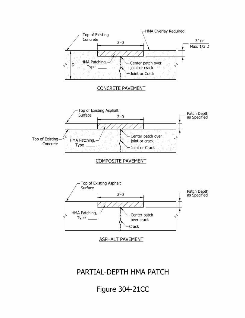
Figure 304-21CC
PARTIAL-DEPTH HMA PATCH
2’-0
2’-0
2’-0
as SpecifiedPatch Depth
Concrete
Top of Existing
Surface
Top of Existing Asphalt
over crack
Center patch
Crack
Type ____
HMA Patching,
Surface
Top of Existing Asphalt
Concrete
Top of Existing
as SpecifiedPatch Depth
Type ____
HMA Patching,
joint or crack
Center patch over
Joint or Crack
Type ____
HMA Patching, joint or crack
Center patch over
Joint or Crack
HMA Overlay Required
CONCRETE PAVEMENT
COMPOSITE PAVEMENT
ASPHALT PAVEMENT
D
Max. 1/3 D
3" or
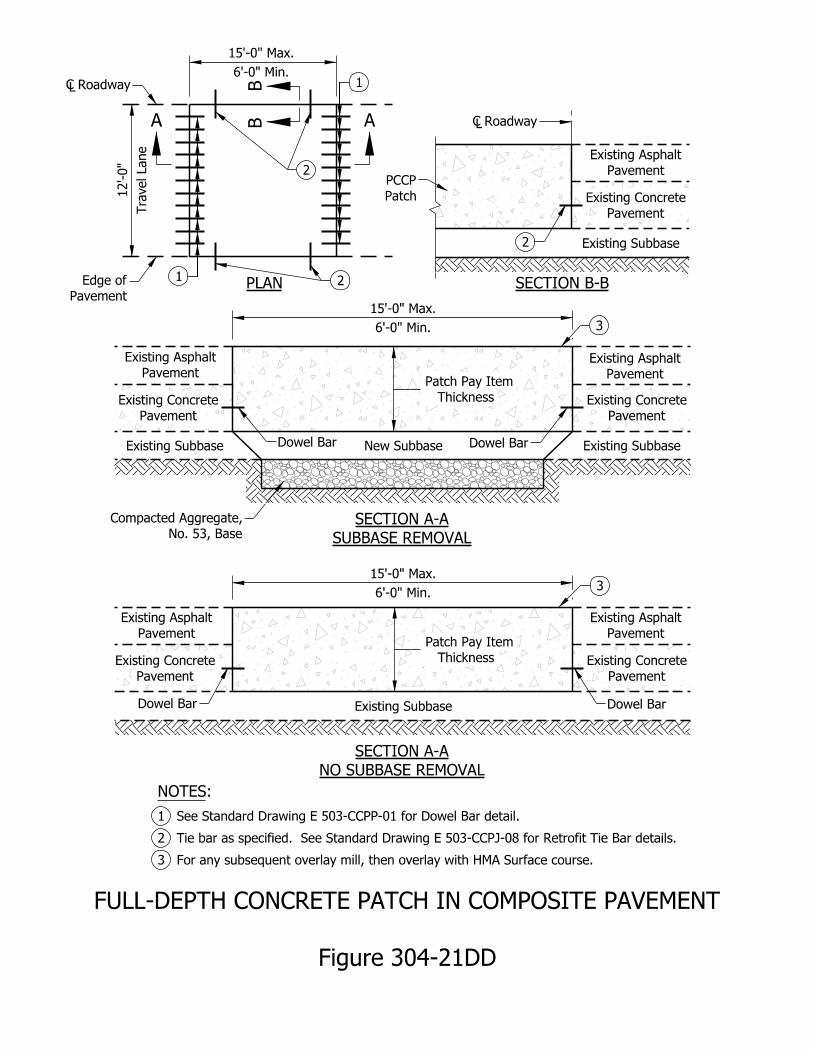
Figure 304-21DD
FULL-DEPTH CONCRETE PATCH IN COMPOSITE PAVEMENT
SECTION B-B
Existing Subbase
Existing Subbase New Subbase Existing Subbase
Existing Subbase
Pavement
Existing Asphalt
Pavement
Existing Asphalt
Pavement
Existing Asphalt
Pavement
Existing Asphalt
Pavement
Existing Asphalt
PLAN
SUBBASE REMOVAL
SECTION A-A
NO SUBBASE REMOVAL
SECTION A-A
6’-0" Min.
15’-0" Max.
6’-0" Min.
15’-0" Max.
Roadway
Dowel Bar
Dowel Bar
2
2
Pavement
Existing Concrete
Pavement
Existing Concrete
Pavement
Existing Concrete
Pavement
Existing Concrete
Pavement
Existing Concrete
Dowel Bar
Dowel Bar
Tra
vel Lane
12’-0"
Pavement
Edge of
Roadway
1
2
1
A
Patch
PCCP
BB
For any subsequent overlay mill, then overlay with HMA Surface course.3
Tie bar as specified. See Standard Drawing E 503-CCPJ-08 for Retrofit Tie Bar details.2
See Standard Drawing E 503-CCPP-01 for Dowel Bar detail.1
:NOTES
No. 53, Base
Compacted Aggregate,
6’-0" Min.
15’-0" Max.
A
3
3
Thickness
Patch Pay Item
Thickness
Patch Pay Item
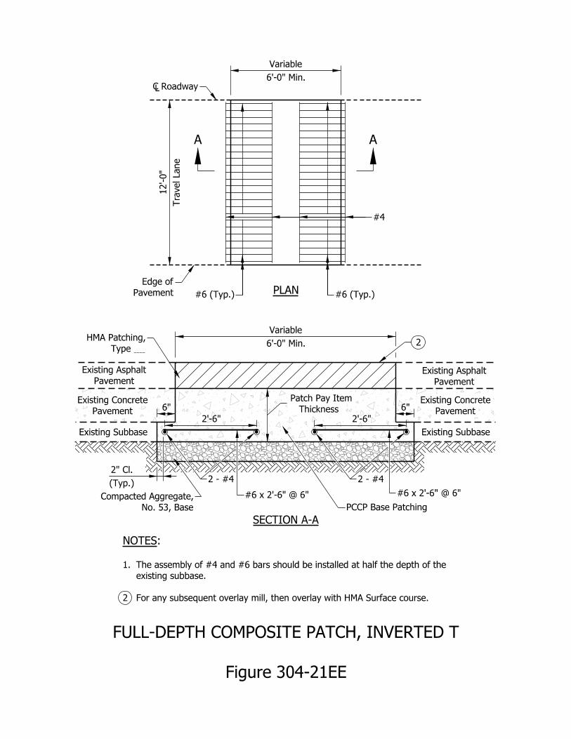
Figure 304-21EE
FULL-DEPTH COMPOSITE PATCH, INVERTED T
For any subsequent overlay mill, then overlay with HMA Surface course.2
existing subbase.
The assembly of #4 and #6 bars should be installed at half the depth of the 1.
:NOTES
PLAN Pavement
Edge of
Roadway
A A
6’-0" Min.
Variable
6’-0" Min.
Variable
Tra
vel Lane
12’-0"
6" 6"
2’-6" 2’-6"
Type
HMA Patching,
Pavement
Existing Asphalt
Pavement
Existing Concrete
Existing Subbase
Pavement
Existing Asphalt
Pavement
Existing Concrete
Existing Subbase
#6 (Typ.)#6 (Typ.)
SECTION A-A
No. 53, Base
Compacted Aggregate,
PCCP Base Patching
2
Thickness
Patch Pay Item
#4
#6 x 2’-6" @ 6" #6 x 2’-6" @ 6"
(Typ.)
2" Cl.
2 - #4 2 - #4
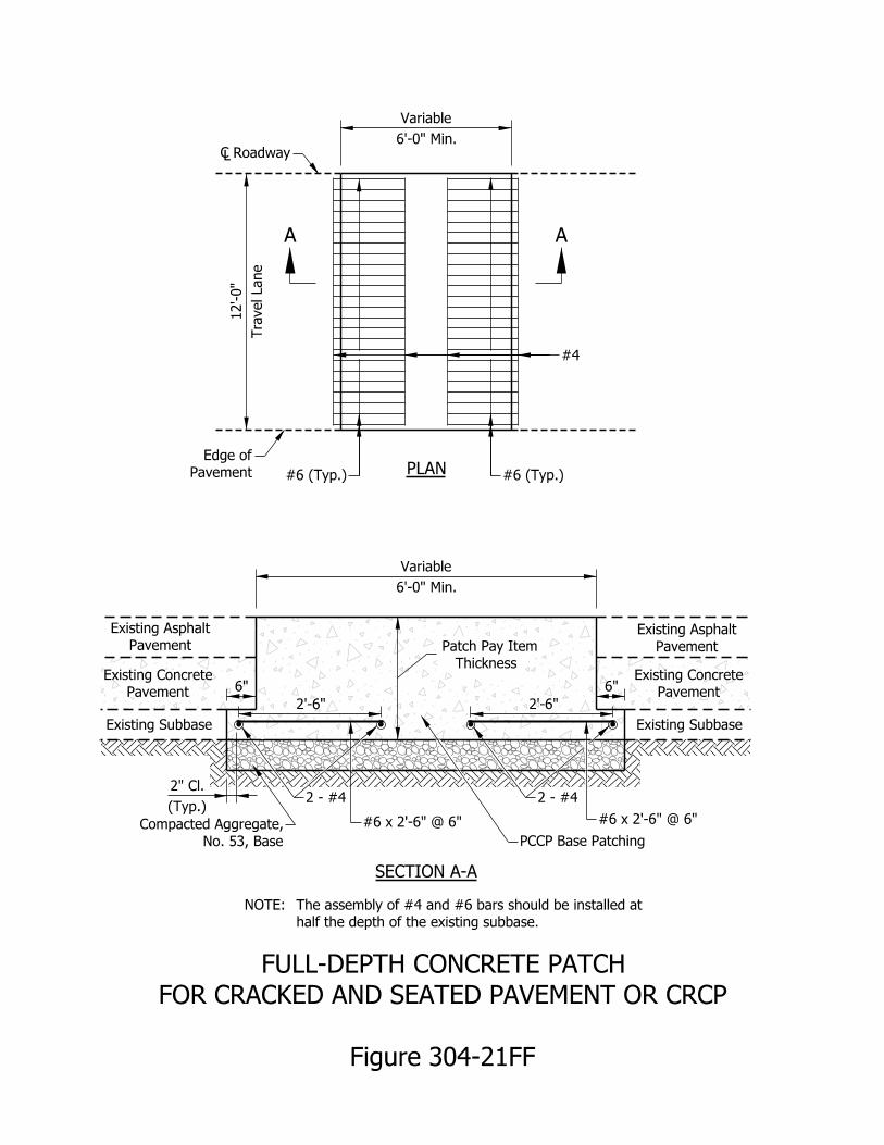
Figure 304-21FF
FOR CRACKED AND SEATED PAVEMENT OR CRCP
FULL-DEPTH CONCRETE PATCH
half the depth of the existing subbase.
The assembly of #4 and #6 bars should be installed at NOTE:
PLAN Pavement
Edge of
Roadway
6’-0" Min.
Variable
6’-0" Min.
Variable
Tra
vel Lane
12’-0"
6" 6"
Pavement
Existing Asphalt
Pavement
Existing Concrete
Existing Subbase
Pavement
Existing Asphalt
Pavement
Existing Concrete
Existing Subbase
SECTION A-A
#6 (Typ.)#6 (Typ.)
2’-6"
No. 53, Base
Compacted Aggregate,
PCCP Base Patching
2’-6"
A A
Thickness
Patch Pay Item
#4
(Typ.)
2" Cl.2 - #4
#6 x 2’-6" @ 6"
2 - #4
#6 x 2’-6" @ 6"