Embed Size (px)
Citation preview

Pneumatic CylindersComposite, round line repairable and disposable,
and NFPA square interchangeable

Table of Contents
Series 01 Micro-Air™ Cylinders1/2", 3/4", & 1-1/8" Bore Sizes . . . . . . . . . . . . . . . . . . .9Application Information, Features, Capabilities . . . . . . .9Ordering Information . . . . . . . . . . . . . . . . . . . . . . . . . .9Mounting Kits . . . . . . . . . . . . . . . . . . . . . . . . . . . . . . .10Dimensional Information . . . . . . . . . . . . . . . . . . . . . . .11Repair Kits . . . . . . . . . . . . . . . . . . . . . . . . . . . . . . . . .56
Series S Silverair™ Cylinders1/2", 3/4", 1-1/16", 1-1/4", 1-1/2", 2" and 2-1/2" Bore SizesApplication Information, Features, Capabilities . . . . . .12Ordering Information . . . . . . . . . . . . . . . . . . . . . . . . .13Mounting Kits . . . . . . . . . . . . . . . . . . . . . . . . . . . .14-15Dimensional Information . . . . . . . . . . . . . . . . . . . .16-22Switches . . . . . . . . . . . . . . . . . . . . . . . . . . . . . . . . . . .23Volume Chambers . . . . . . . . . . . . . . . . . . . . . . . . . . . .24
Premair™ Series Composite Cylinders7/16", 9/16", 3/4", 1-1/16", 1-1/4", 1-1/2" and 2" Bore SizesApplication Information, Features, Capabilities . . . . . .25Ordering Information . . . . . . . . . . . . . . . . . . . . . . . . .26Mounts, Dimensional Information . . . . . . . . . . . . . . . .27Switches . . . . . . . . . . . . . . . . . . . . . . . . . . . . . . . . . . .31Dimensional Information . . . . . . . . . . . . . . . . . . . .28-33
Series 23, 24 and 28 Economair® Cylinders1-1/8", 1-1/2", 2", 2-1/2", 3" and 4" Bore SizesApplication Information, Features, Capabilities . . . . . .34Ordering Information . . . . . . . . . . . . . . . . . . . . . . . . .35Mounting Kits . . . . . . . . . . . . . . . . . . . . . . . . . . . .35-36Dimensional Information . . . . . . . . . . . . . . . . . . . .37-38Switches . . . . . . . . . . . . . . . . . . . . . . . . . . . . . . . . . . .39Repair Kits . . . . . . . . . . . . . . . . . . . . . . . . . . . . . . . . .56
Series N Provenair® Cylinders1-1/2", 2", 2-1/2", 3-1/4", 4", 6", 8" and 10" Bore SizesApplication Information, Features, Capabilities . . .41-42Series AN (aluminum) . . . . . . . . . . . . . . . . . . . . . . . . .43Series SN (stainless steel) . . . . . . . . . . . . . . . . . . . . .44Mounting Kits . . . . . . . . . . . . . . . . . . . . . . . . . . . .45-46Dimensional Information (Series AN, SN) . . . . . . .47-51Switches (Series AN) . . . . . . . . . . . . . . . . . . . . . . .54-55Rod End Accessories (Series AN) . . . . . . . . . . . . . . . .52Repair Kits . . . . . . . . . . . . . . . . . . . . . . . . . . . . . . .56-57Tanks and Reservoirs, 1-1/2" thru 4" . . . . . . . . . .53, 55Rod Alignment Couplers . . . . . . . . . . . . . . . . . . . . . . .40Warranties . . . . . . . . . . . . . . . . . . . . . . . . . . . . . . . . . .82
Premair™ Series Round Compact Cylinders1/2", 3/4", 1-1/8", 1-1/2", 2", 2-1/2", 3", 4"Application Information, Features, Capabilities . . .59-60Ordering Information . . . . . . . . . . . . . . . . . . . . . . . . .61Accessories . . . . . . . . . . . . . . . . . . . . . . . . . . . . . . . . .62Switches . . . . . . . . . . . . . . . . . . . . . . . . . . . . . . . . . . .63Dimensional Information . . . . . . . . . . . . . . . . . . . .64-66Repair Kits . . . . . . . . . . . . . . . . . . . . . . . . . . . . . . . . .74
Premair™ Series Square Metric Compact CylindersApplication Information, Features, Capabilities . . . . . .68Ordering Information . . . . . . . . . . . . . . . . . . . . . . . . .69Mounts, Dimensional Information . . . . . . . . . . . . .71-73Switches . . . . . . . . . . . . . . . . . . . . . . . . . . . . . . . . . . .74Dimensional Information . . . . . . . . . . . . . . . . . . . .70-73Repair Kits . . . . . . . . . . . . . . . . . . . . . . . . . . . . . . . . .74
AccessoriesAir System Components . . . . . . . . . . . . . . . . . . . .77-80Flow Controls . . . . . . . . . . . . . . . . . . . . . . . . . . . . .75-76
Economair® and Provenair® are registered trademarks of Aro.

2
Pneumatic Cylinders
Series S Silverair™ Cylinders(1/2" thru 2-1/2" bore)
Silverair Cylinders, small and medium bore, disposable,single- and double-acting cylinders are designed for lightduty applications. Available in bore sizes from 1/2 inch to 2-1/2 inches. Operate on air pressures to 200 PSI, generatingthrusts up to 982 pounds. For more information, see pages12 through 24.
Premair™ Composite Cylinders(7/16" thru 2" bore)
Featuring a patented composite body construction, the new Premair cylinder is ideal in assembly environments where corrosive (including wet or wash down) conditions exist.Premair’s composite construction is also dent-resistant,lighter weight, quieter and provides superior service lifewhen compared to metal cylinders. Available in 7 bore sizesand 3 types (double-acting, spring extend, spring retract);Premair offers a broad spectrum of trouble-free linearmotion. For more information, see pages 25 through 33.
Series 01 Micro-Air™ Cylinders(1/2" thru 1-1/8" bore)
Micro-Air Cylinders, small bore, repairable, double-actingcylinders, are designed for light duty applications. Availablein 1/2, 3/4, and 1-1/8 inch bore sizes. Operate on airpressure to 200 PSI, generating thrusts from 4.9 to 199pounds. They are available in stroke lengths up to 6 inchesand in several mounting styles. For more information, seepages 9 through 11.
Series 23, 24 & 28 Economair ® Cylinders (1-1/8" thru 4" bore)Economair Cylinders, round line repairable cylinders, aredesigned for medium to heavy-duty use in a wide range ofapplications. Available in 1-1/8 to 4-inch bore sizes.Operate on air pressure to 200 PSI, generating thrusts from25 to 2,513 pounds. Available as double-acting, withoptional cushions, magnetic pistons or double rod ends. O-ring seals are standard. U-cup or low friction seals areoptional. A variety of mounts are available to meet a widerange of application requirements. For more information, see pages 34 through 39.
Descriptions

Pneumatic Cylinders
3
Series AN & SN Provenair® Cylinders(1-1/2" thru 10" bore)Provenair Cylinders are NFPA interchangeable square headcylinders designed for rugged use. Available in 1-1/2 to 10-inch bore sizes. They operate on air pressure up to 250 PSI,generating thrusts up to 3,141 pounds. They are availableas double-acting, with optional cushions, magnetic pistonsand/or with double rod ends. A broad selection of NFPA standard mounts makes them dimensionallyinterchangeable with other NFPA cylinders. For moreinformation, see pages 41 through 55.
Premair™ Series Round Compact Cylinders(1/2" thru 4" bore)
Premair Round Compact Cylinders are available in 8 boresizes, from 1/2” thru 4”. They are designed for light tomedium duty applications and are interchangeable with theleading manufacturer of round compact cylinders. Thesecylinders are available in single or double acting, and with avariety of mounting, seal and magnetic options. For moreinformation, see pages 59 through 67.
Premair™ Series Square MetricCompact Cylinders(12mm thru 160mm bore)Premair Square Metric Compact Cylinders are available in 13bore sizes, from 12mm thru 160mm. All cylinders come withNPT Ports and inch threads on rod end, and magnetic pistonas standard. Mounting through holes are tapped and accepta variety of mounting kits. These cylinders interchange withthe leading manufacturers of Square Compact Cylinders. Formore information, see pages 68 through 74.
Descriptions

Pneumatic Cylinders
4
MountsMicro-Air™Silverair™Premair™Economair®
Provenair® (1-1/2 thru 10-inch bore)Provenair® Stainless Steel (1-1/2 thru 8-inch bore)
Rod End AccessoriesMicro-Air™Silverair™Premair™Economair®
Provenair® (1-1/2 thru 10-inch bore)
Alignment Couplers
Switches, Cylinder Mounted
Flow Control Valves
Volume Chambers
Repair Kits
Mounts
Alignment Couplers
Rod End Accessories
Electrical Switches
Right Angle Flow Controls
Accessories

Pneumatic Cylinders
Developing SpecificationsCalculating the Proper Bore SizeA cylinder’s bore size determines the force it will produce at a given supplypressure. The weight of the load or the clamping force required will largelydetermine the force requirements of the cylinder, and hence, the bore sizerequired. But before determining the appropriate bore size you mustcompensate for air pressure drop, packing friction and load variations usingthe following computation:
A) Compensating for Pressure Drop – Decrease the line pressure value by15 p.s.i. This compensates for pressure drop in the system.
Operating pressure (psig) = Line pressure (psig) less 15 (psigpressure drop)
Example: If the line pressure is 95 (psig), subtract 15 (psig) toobtain 80 (psig) operating pressure (for sizing purposes).
B) Compensating for Packing Friction – Before you begin selecting a cylinder you already know the weight of the load youmust move or the clamping force you must apply. Multiply this force or load value by 1.25. This compensates forpacking friction and load variations. (If speed is of concern for your application, multiply the force value by 2.0.)
Force required (in pounds) = 1.25 x load (or required clamping force)
Example: If cylinder must move 100 pound load, multiplying 100 pounds by 1.25 = 125 pounds force required.
Now, at the top of the chart on the next page, find the column with the operating pressure calculated in “A” above (in thisexample, 80 psig). Go down that column until you find the force requirement calculated in “B”, above (or the next highervalue). Note that the force values in bold type represent the extend force while those in standard type represent retract force(retract force is lower because the rod reduces the effective piston area). Choose the appropriate value, then go to theCylinder Bore column to find the bore requirements for your application.
Now that you know the cylinder bore size that will produce the force required for your application, go to page 7 to determinerod size requirements.
Air consumption for each cylinder bore size can be found in the chart below.
Downstream pressurebecause of pressure
loss in lines:80 psi
pressure loss in lines
Air pressure atsource. 95 psi
LOAD
LoadFriction
PackingFriction
This illustration shows a pressure loss of 15 PSI throughthe airlines and points out friction factors, both of whichmust be compensated for.
2-inch cylinder
5/8-inch diameter227 pounds of force
251 poundsof force
200
180
160
140
120
100
80
60
40
20
.001 .0015 .002 .003 .004 .006 .008 .01 .015 .02 .03 .04 .06 ..08 .10 .15 .20 .30 .40 ..60
GAU
GE
PRES
SURE
– P
SIG
CU. FT. FREE AIR – (SCFM FACTOR)
1/2" B
ORE
3/4" B
ORE
1-1/8
" BOR
E
1-1/2
" BOR
E2"
BOR
E2-
1/2" B
ORE
3" B
ORE
4" B
ORE
3-1/4"
BORE
5" B
ORE
6" B
ORE
8" B
ORE
Given equal pressure on both sides of a piston, the surface area on the extendside will provide greater force.
Cylinder Air ConsumptionTo calculate the air consumption of a cylinder, multiply the total inches of stroke(extend plus retract) by the cycles per minute times the SCFM factor from the chartbelow. To find the SCFM factor, find your gauge pressure in the left hand column.Next, find your cylinder bore size in the chart. Where the two intersect, read down tothe SCFM factor at the bottom of the chart.
5

Pneumatic Cylinders
6
Bore Selection Sizes EFFECTIVE PISTON AREA X OPERATING PRESSURE = FORCE
SELECTING BORE SIZE FORCE OR LOAD VALUE
VALUES IN BOLD TYPE REPRESENT EXTEND FORCE. Other values represent retract force (piston area, less area of piston rod).Check series order information for available rod diameters in each series.
EFFECTIVECYLINDER ROD PISTON
BORE DIAMETER AREA OPERATING PRESSURE (PSI)(INCHES) (INCHES) (SQ. IN.) 20 40 60 70 80 90 100 110 125 150 200
7/16 .15 3 6 9 10 12 13 15 16 18 22 303/16 .123 2.5 4.9 7,4 8.6 9.8 11 12.3 13.5 15.4 18.5 24.6
1/2 .196 4 8 12 14 16 18 20 22 25 29 393/16 .169 3 7 10 12 14 15 17 19 21 25 341/4 .147 3 6 9 10 12 13 15 16 18 22 29
9/16 .25 5 10 15 17 20 22 25 27 31 37 503/16 .23 4.5 8.9 13.4 15.6 17.8 20 22 29.5 27.9 33.5 44.6
3/4 .442 9 18 27 31 35 40 44 49 55 66 881/4 .393 8 16 24 28 31 35 39 43 49 59 79
7/8 .604 12 24 36 42 48 54 60 66 75 90 1201/4 .553 11 22 33 38 44 49 55 60 69 82 110
1-1/16 .890 18 36 53 62 71 80 89 98 111 134 1785/16 .810 16 32 49 57 65 73 81 89 101 122 162
1-1/8 .994 20 40 60 70 80 89 99 109 124 149 1995/16 .917 18 37 55 64 73 83 92 101 115 138 1833/8 .884 18 35 53 62 71 80 88 97 110 133 177
1-1/4 1.227 25 49 74 88 98 110 123 135 153 184 2457/16 1.077 22 43 65 75 86 97 108 118 135 162 215
1-1/2 1.767 35 71 106 124 141 159 177 194 221 265 3537/16 1.617 32 65 97 113 129 146 162 178 202 243 3231/2 1.571 31 63 94 110 126 141 157 173 196 236 3145/8 1.460 29 58 88 102 117 131 146 161 183 219 2921 1.325 27 53 80 93 106 119 133 146 166 199 265
1-3/4 2.405 48 96 144 168 192 216 240 265 301 361 4811/2 2.209 44 88 133 155 177 199 221 243 276 331 442
2 3.142 63 126 189 220 251 283 314 346 393 471 6285/8 2.835 57 113 170 198 227 255 284 312 354 425 5671 2.700 54 108 162 189 216 243 270 297 338 405 540
2-1/2 4.910 98 196 295 344 393 442 491 540 614 737 9825/8 4.602 92 184 276 322 368 414 460 506 575 690 9203/4 4.470 89 179 268 313 358 402 447 492 559 671 8941 4.123 82 165 247 289 330 371 412 454 515 618 825
3 7.069 141 283 424 495 566 636 707 778 884 1060 14143/4 6.6268 133 265 398 464 530 596 663 729 828 994 1325
3-1/4 8.296 166 332 498 581 664 747 830 913 1037 1244 16591 7.510 150 300 451 526 601 676 751 826 939 1127 1502
1-3/8 6.810 136 272 409 477 545 613 681 749 851 1021 13624 12.566 251 503 754 880 1005 1131 1257 1382 1571 1885 2513
1 11.781 236 471 707 825 942 1060 1178 1296 1473 1767 23561-3/8 11.081 222 443 665 776 886 997 1108 1219 1385 1662 2216
5 19.635 393 785 1178 1374 1571 1767 1964 2160 2454 2945 39271 18.850 377 754 1131 1320 1508 1697 1885 2074 2356 2828 3770
1-3/8 18.150 363 726 1089 1271 1452 1634 1815 1996 2269 2723 36306 28.274 565 1131 1696 1979 2262 2545 2827 3110 3534 4241 5655
1-3/8 16.789 536 1072 1607 1875 2143 2411 2679 2947 3349 4018 53581-3/4 25.870 517 1035 1552 1811 2070 2328 2587 2846 3234 3881 5174
8 50.260 1005 2010 3016 3518 4021 4523 5026 5529 6283 7539 100521-3/8 48.770 975 1951 2926 3414 3902 4489 4877 5365 6096 7316 97541-3/4 47.820 956 1913 2869 3347 3826 4304 4782 5260 5978 7173 9564
10 78.54 1571 3142 4712 5497 6283 7068 7854 8639 9818 11781 157081-3/4 76.14 1523 3046 4568 5330 6091 6853 7614 8375 9518 11421 15228
Pneumatic Cylinders
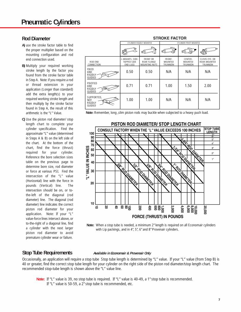
Stop Tube Requirements Available in Economair & Provenair Only
Occasionally, an application will require a stop tube Stop tube length is determined by “L” value. If your “L” value (from Step B) is40 or greater, find the correct stop tube length for your cylinder on the right side of the piston rod diameter/stop length chart. Therecommended stop-tube length is shown above the “L” value line.
Note: If “L” value is 39, no stop tube is required. If “L” value is 40-49, a 1" stop tube is recommended.If “L” value is 50-59, a 2" stop tube is recommended, etc.
L-MOUNTS, SIDE- FRONT OR FRONT- CENTER- CLEVIS EYE. ORROD END TAPPED SIDE REAR FLANGE MOUNTED MOUNTED REAR-MOUNTED
CONNECTION END LUGS MOUNTING NUTS TRUNNION TRUNNION TRUNNION
FIXEDAND 0.50 0.50 N/A N/A N/ARIGIDLYGUIDED
PIVOTED AND 0.71 0.71 1.00 1.50 2.00RIGIDLYGUIDED
SUPPORTED,NOT 1.00 1.00 N/A N/A N/ARIGIDLY GUIDED
Note: When a stop tube is needed, a minimum 2" length is required on all Economair cylinderswith Lip packings, and in 4", 5", 6" and 8" Provenair cylinders.
CYLINDER RIGIDLY MOUNTED CYLINDER PIVOT MOUNTED
STROKE FACTOR
Note: Remember, long ,slim piston rods may buckle when subjected to a heavy push load.
Rod DiameterA) use the stroke factor table to find
the proper multiplier based on themounting configuration and rodend connection used.
B) Multiply your required workingstroke length by the factor youfound from the stroke factor tablein Step A. Note: if you require a rodor thread extension in yourapplication (Longer than standard)add the extra length(s) to yourrequired working stroke length andthen multiply by the stroke factorfound in Step A, the result of thisarithmetic is the “L” Value.
C) Use the piston rod diameter/ stoplength chart to complete yourcylinder specification. Find theapproximate “L” value (determinedin Steps A & B) on the left side ofthe chart. At the bottom of thechart, find the force (thrust)required for your cylinder.Reference the bore selection sizestable on the previous page todetermine bore size, rod diameteror force at various PSI. Find theintersection of the “L” value(Horizontal) line with the force inpounds (Vertical) line. Theintersection should be on, or to-the-left of the diagonal (roddiameter) line. The diagonal (roddiameter) line indicates the correctpiston rod diameter for yourapplication. Note: If your “L”value-force lines intersect above, orto-the-right of a diagonal line, finda cylinder with the next largerpiston rod diameter to avoidpremature cylinder wear or failure.
7

8
Pneumatic Cylinders
OptionsAdditional options required will help determine which cylinder series will be selected:
Stainless steel piston rods are beneficial in corrosive environments. Stainless steel rods are standard on Micro-Air and SilverairSeries. Stainless Steel rods are options on Economair and Provenair Series.
Cylinder cushions are designed to reduce the shock experienced at the end of the stroke by reducing piston speed the last fractionof an inch of stroke. Cylinder cushions are available in Economair and Provenair Series, only.
Packing shape and material affect cylinder performance:• O-Ring packings are good, general purpose packings, but they require more breakaway force than other packing shapes.
• O-Ring – Low Friction packings provide the effective sealing characteristics of Buna N with the low friction characteristics ofTeflon®. This design is effective where the cylinder must operate at low pressures.
• U-Cup packings offer low breakaway friction and better sealing characteristics at low pressure than O-Ring packings. U-cupsare wear compensating seals; they offer longer wear life than O-rings.
• U-Cup – Self Lube (“Slippery Seals”) packings are ideal in applications where air line lubrication cannot be used. This packingdesign helps reduce cylinder “chatter” in low pressure applications and it offers the same sealing characteristics as Buna N.
Packing Characteristics
Teflon® and Viton® are registered trademarks of the E.I. DuPont Company.
Sealing Friction TemperatureMaterial Characteristics Characteristics Tolerance Availability
O-RING Teflon over Good Medium 0° to 180° F EconomairBuna N O-Ring Seal
O-RING Buna N Good High 0° to 180° F Micro-Air, EconomairO-RING Viton® Good High Up to 300° F Micro-Air, EconomairU-CUP-SELF-LUBE
(“Slippery Seals") Nitrile Very Good Low 0° to 180° F Economair, ProvenairU-CUP Buna N Very Good Medium 0° to 180° F Economair, ProvenairU-CUP Viton Very Good Medium Up to 300° F Economair, Provenair
Note: When applying rod cylinders, there must be no side load or bending stress at any point along the rod. Applications which induce side load and/or bendingstress will damage packings, bushings, piston barrels, piston rods and cushion bosses. When metal parts are damaged, seal and packing replacement is aninadequate repair. The elastomers will quickly become damaged. Inspect and replace all worn or damaged parts when rebuilding cylinders.

9
Pneumatic CylindersMicro-Air
Features
Performance Specs
Ordering
Micro-Air Cylinders are ideal for small part positioning, clamping and ejecting. Also they’re the perfectchoice for applications where small bore, medium duty, repairable cylinders are preferred. Prelubed,they’re suitable for operations without externally applied lubrication.
• Micro-Air Cylinders are repairable. Service kits are available to extend the useable life of the cylinder.
• Micro-Air Cylinders operate on air pressure to 200 p.s.i. (14 bar). A tough little cylinder that canhandle the pressures!
• Superior performance over a wide temperature range – 0° to 180° F (-18° to 82° C), even to 300°F (149° C) when Viton seals are used (consult factory).
• Micro-Air Cylinders have superior wear characteristics, thanks to the hard coated aluminum tubingI.D. In addition to an internal hardness of 60 Rockwell C, the barrel has an internal finish of 16microinches or better.
• Micro-Air Cylinders are equipped with Series 303 stainless steel piston rods for corrosion resistance.Also, the ground and polished finish on the rods minimizes friction, providing longer packing life.
• Micro-Air Cylinders provide greater durability than disposable cylinders.
• Double end-mount cylinders can also be used as a pivot mount. Pivot pin included with each cylinder.
Bore Sizes: 1/2”, 3/4”, and 1-1/8”
Maximum Output Force: 199 pounds (1-1/8” bore)
Standard Operating Temperature range: 0° to 180° F (-18° to 82° C)
Viton Seals Models: For high heat applications. Consult factory.
Range of mounting styles and attachable mounts/ accessories to meet nearly any applicationrequirement.
Series 01
01 XX - XXXX - 0 XX
STROKE LENGTHWHOLE INCHES FRACTIONS
0 = 0 in 0 = None1 = 1 in 1 = 1/8 in2 = 2 in 2 = 1/4 in3 = 3 in 3 = 3/8 in4 = 4 in 4 = 1/2 in5 = 5 in 5 = 5/8 in6 = 6 in 6 = 3/4 in
7 = 7/8 in
CYLINDER TYPE AND MOUNTING STYLE1009 Double Acting, Double End Mount and Pivot Mount, BUNA-N Seals5029 Double Acting, Nose Mount, Rear Port, BUNA-N Seals1309 Double Acting, Double End Mount and Pivot Mount, Viton Seals5329 Double Acting, Nose Mount, Rear Port, Viton Seals
BORE SIZE51 1/2 in76 3/4 in.18 1-1/8 in.
Maximum stroke length - 6-7/8-inches.Consult factory for the other strokerequirements.
NOTE: Highlighted selections denote most popular models.
(1/2” Increments, 1/2” through 6”)

10
Pneumatic CylindersMicro-Air
Dimensional Data
Ordering
Series 01
Mounting Kit
.199 Dia. Mounting Hole, 2 Pl.
.688 Dia. Hole
1.375
.875
.375
.750
1.250
.875
.125
.625.125
L-Mount
.875
.078
.656
.688 Sq.
1.375 Sq.
.688 Dia. Hole
.199 Dia. Mounting Hole, 4 Pl
1.750 Sq.
Rod Clevis & Clevis Bracket
1.125
1.125
.875
.625 .6875
.813
.125
.199 Dia Mounting Hole, 2 Pl.
.250 Dia. Hole
.125.50 .625
1.031
.25.25
.25
.50
.25 Dia. Pin
1/2” and 3/4” Bore: 1/4-281-1/8” Bore: 5/16-18
Front Flange Rear Flange Mounting Nut.25
5/8-18 Thread
3/4 Hex
Trunnion
DE
A
F
G
HJ
H
J
A
B
C
A/2
A 1.50 1.50 2.25B .625 .625 .875C Dia. .703 .953 1.391D .500 .500 .750E .250 .250 .375F Dia. – – .563G Dia. ± .002 .250 .250 .437H ± .010 .250 .250 .438J – – .0625
Cylinder Bore (Inches)Reference 1/2 3/4 1-1/8
Trunnion Dimensions
* 20561 Trunnion Bracket Kit (right andleft brackets) is used for 20523Trunnion. Reference Clevis bracketdimensions.
Cylinder Bore (Inches)1/2 3/4 1-1/8
L-MOUNTS (2 Qty) * 20515 20515 20515
FLANGE MOUNT * 20516 20516 20516
MOUNTING NUT (2 Qty) 20514-1 20514-1 20514-1
CLEVIS BRACKET 20519 20519 20519
TRUNNION - 20523 20524
TRUNNION BRACKETS - 20561 –
ROD CLEVIS 20517 20517 20518-1
* NOTE: Mounting nuts included.

11
Pneumatic CylindersMicro-Air
Dimensional Data
Rod Diameter 1/4 1/4 5/16AA 2.438 2.438 2.688
BB .625 .625 .625
CC .750 .750 .750
CB 1.375 1.375 1.375
DD .047 .047 .047
EE .281 .281 .281
FF* .719 .719 .719
GG (± .002) .682 .682 .682
HH 1/4-28 1/4-28 5/16-18.UNF .UNF .UNC
JJ (UNF-2A) 5/8-18 5/8-18 5/8-18
KK 2 2 2
LL (NPTF) 1/8-27 1/8-27 1/8-27
MM .787 .912 1.350**
PP .375 .375 .375
QQ (SLOT) .130 .130 .130± .002
RR (PIN) .250 .250 .250
SS .625 .625 .625
TT DIA. .700 .950 1.375* Note: FF shows total thread, including run out.
** On rear head only of 5029 dimension is 1.291.
CYLINDER BORE (INCHES)Reference 1/2 3/4 1-1/8
01XX-1X09 BasicDouble End / Pivot Mount
Series 01
01XX-5X29 BasicRear Port

12
Pneumatic CylindersSilverair™
Features
Silverair round cylinders are designed for application in OEM and MRO applicationswhere a disposable, light duty cylinder is preferred. Prelubed, they’re suitable foroperations without externally applied lubrication. Constructed of stainless steel andaluminum, they stand up to the attack of corrosive environments.
• Silverair cylinders feature stainless steel (Series 304) barrels. Drawn andpolished internal diameters have superior lube-holding characteristics for a lowfriction surface that gives smooth performance and outstanding cycle life.
• Piston rods are centerless ground and polished Series 303 stainless steel,providing smooth rod movement.
• Lightweight aluminum heads feature full flow ports for maximum air flow andsmooth response.
• Piston rod threads are roll formed to provide superior strength and durability.
• U-cup design on piston seals provides continuous cylinder barrel contact,minimizes blow-by and offers longer seal life than O-ring piston seals.
• The oil-permeated bronze rod bushing is precision ball sized for reducedfriction and increased cylinder life.
• Return springs on single-acting cylinders are made from a high tensile alloy forexceptional performance and long service life.
• Silverair cylinders are prelubricated, so they’re ideal in applications whereexternal lubrication can’t be supplied.
Series S
See following page.
Ordering
Performance SpecificationsBore Sizes: 1/2”, 3/4”, 1-1/16”, 1-1/4”, 1-1/2”, 2” and 2-1/2”Air Pressure: to 200 p.s.i. (14 bar)Operating Temperature Range: -40° to 160° F (18° to 82° C)Maximum Output Force: 982 pounds (2-1/2-inch bore cylinder)Viton Seals Models: For high heat applications. Consult factory.
Range of mounting styles and attachable mounts/accessories covers wide range of application requirements.Magnetic pistons available for use with Hall Effect or Reed Switches.

13
Pneumatic CylindersSilverair™
S X XX - X X X X - XXX
CYLINDER TYPES Single Acting, Spring Return (Not available on 25 bore size)D Double ActingR Single Acting, Spring Extend (Not available on 25 bore size)H Single Acting, Hex Rod (Non-rotating rod)
(Spring return only)Not available on 14,17,20or 25 bore sizes)
SERIESS Stainless Steel
Include dashes. Dashes are significant.
STROKE LENGTHWHOLE INCHES FRACTIONS
00 = 0 in 0 = None01 = 1 in 1 = 1/8 in02 = 2 in 2 = 1/4 in03 = 3 in 3 = 3/8 in04 = 4 in 4 = 1/2 in05 = 5 in 5 = 5/8 in06 = 6 in 6 = 3/4 in10 = 10 in 7 = 7/8 inetc.
For recommended maximum stroke lengths,per type, see pages 16 through 21.
MOUNTING STYLEB Block Mount (Available on 05, 07, 11 and 15 bore size only)
(Not available on type SH)D Double Rod End (Double Acting Only)N Nose Mount P Universal Mount (Pivot or Double End)Silverair attachable mounts must be ordered separately.See page 14.
MAGNET/ BUMPERS (Note A)4 No Bumpers, no magnetB BumpersM Magnetic Piston (Not available in 1/2"
bore or for single-acting cylinders).For switch information, see page 23.
WEARSTRIP (Note B)4 None (standard)W Wearstrip
PACKINGB Buna NV Viton
BORE SIZE05 1/2 in07 3/4 in.11 1-1/16 in.14 1-1/4 in. (Not available on type SH)15 1-1/2 in.17 1-3/4 in. (Not available on type SH)20 2 in. (Not available on type SH)25 2-1/2 in. (Not available on type SS, SR or SH)
Note A: Bumpers• Not available with magnetic piston option.• Standard on double rod ends.• Do not affect external dimensions.
Note B: Wearstrip is standard on double-acting nose mount, universal mount andblock front mount of 5" or more of stroke. Also on single acting, spring extend cylinders with 3" or more of stroke. Not available on 1/2" bore cylinders. Not available on single acting, hex rod (non-rotating rod)
Note: Highlighted selections denote most popular models.
(1/2" Increments, 1/2" through 6")
Ordering

14
Pneumatic CylindersSilverair™
CYLINDER BORE (INCHES)1/2 3/4 1-1/16 1-1/4 1-1/2 1-3/4 2 2-1/2
Mounting Nut
L-Mount
Block Front Mount
Pivot Bracket and Rod Clevis
* FOR DOUBLE END MOUNTING OF SINGLE-ACTING CYLINDERS, ORDER THE FOLLOWING:1/2-inch bore One 118108-5 L-Mount and one 118109-5 Nut for rear mounting thread. One 118108-50 L-Mount and
one 118109-50 Nut for front mounting thread.3/4-inch bore Two 118108-7 L-Mounts, one 118109-7 Nut for rear mounting thread and one 118109-11 Nut for front
mounting thread.
NOTE: Silverair accessories are bright zinc plated steel.
Series S (Mounting Kits)
L-MOUNT (Single Acting)
Order Mounting Nut below.
118108-5 118108-7 118108-11 118108-14 118108-14 118108-17 118108-20 118108-25
L-MOUNT (Double Acting)
Order Mounting Nut below.
118108-50 118108-11 118108-11 118108-14 118108-14 118108-17 118108-20 118108-25
MOUNTING NUT (Single Acting*)
118109-5 118109-7 118109-11 118109-14 118109-14 118109-17 118109-20 118109-25
MOUNTING NUT (Double Acting)
118109-50 118109-11 118109-11 118109-14 118109-14 118109-17 118109-20 118109-25
PIVOT BRACKET (Pivot Pin Included)
117523-5 117523-7 117523-7 117523-14 117523-15 117523-15 117523-20 117523-20
ROD CLEVIS (Pivot Pin Included)
117555-5 117555-7 117555-11 117555-14 117555-14 117555-17 117555-17 117555-17
PIVOT PINS (Standard Equipment)
Pin
118119-5 118119-7 118119-7 118119-14 - - 118119-20 -
Retainer
118592-5 118592-5 118592-5 118592-5 118592-15 118592-15 118592-15 -
Optional Press Fit Pin
118121-5 118121-7 118121-7 118121-14 118121-15 118121-15 – -
Ordering

15
Pneumatic CylindersSilverair™
A B
C
A D
C
B
E
H
J
F
G
D
C
E
J
H
GF
A B
L-Mount
Mounting Nut
Pivot Bracket
ASQ
D
C
B
E
HG
F
Rod Clevis
A
A
B
B C
Pivot Pins
Dimensional DataSeries S (Mounting Kit)
CYLINDER BORE (INCHES)1/2 3/4 1-1/16 1-1/4 1-1/2 1-3/4 2 2-1/2
Dim Single Double Single Double All All All All All AllRef Acting Acting Acting Acting Types Types Types Types Types Types
L-Mount BracketA .31 .31 .44 .56 .56 .75 .75 .94 1.00 1.00B .19 .19 .19 .27 .27 .28 .28 .34.34 .34 .34C .62 .62 .75 1.00 1.00 1.50 1.50 1.50 1.62 1.62D 1.00 1.00 1.25 1.50 1.50 1.89 1.89 2.25 2.25 2.88E .37 .37 .40 .56 .56 .75 .75 .88 1.00 1.25F .38 .44 .50 .63 .63 .76 .76 1.04 1.38 1.50G 56° 56° 45° 45° 45° 49° 49° 52° 60° 63°H .57 .57 .69 .81 .81 1.00 1.00 1.25 1.50 1.75J 1.38 1.38 1.63 1.88 1.88 2.50 2.50 3.00 3.00 3.75
Mounting NutA .56 .68 .75 .93 .93 1.12 1.12 1.50 1.85 2.06B .22 .25 .31 .37 .37 .42 .42 .56 .50 .50C 3/8-24 7/16-20 1/2-20 5/8-18 5/8-18 3/4-16 3/4-16 1-14 1-1/4-12 1-3/8-12
CYLINDER BORE (INCHES)1/2 3/4 1-1/16 1-1/4 1-1/2 1-3/4 2 2-1/2
Dim All All All All All All All AllRef Types Types Types Types Types Types Types Types
Pivot BracketA .20 .26 .26 .32 .39 .39 .45 .45B .52 .65 .65 .77 .96 .96 1.20 1.20C .43 .75 .75 .75 1.00 1.00 1.00 1.00D .54 .87 .87 .94 1.25 1.25 1.43 1.43E .22 .31 .31 .31 .38 .38 .38 .38F .16 .26 .26 .26 .38 .38 .38 .38G 50° 53° 53° 53° 52° 52° 48° 48°H .64 .87 .87 1.06 1.37 1.37 1.68 1.68J .75 1.19 1.19 1.25 1.63 1.63 1.81 1.81
Rod ClevisA .38 .50 .50 .75 .75 .75 .75 .75B .19 .25 .25 .38 .38 .38 .38 .38C .75 .94 .94 1.30 1.30 1.30 1.30 1.30D .38 .50 .50 .75 .75 .75 .75 .75E 10-32 1/4-28 5/16-24 7/16-20 7/16-20 1/2-20 1/2-20 1/2-20F .19 .25 .25 .38 .38 .38 .38 .38G .94 1.20 1.20 1.70 1.70 1.70 1.70 1.70H .12 .16 .16 .25 .25 .31 .31 .31
Pivot PinAs supplied with Pivot Bracket:
A .69 .81 .81 .94 1.13 1.13 1.44 1.44B .15 .25 .25 .25 .37 .37 .37 .37
For press fit into pivot hole:A .50 .75 .75 .87 1.12 1.12 – –B .15 .24 .24 .24 .37 .37 – –C .17 .26 .26 .26 .39 .39 – –

16
Pneumatic CylindersSilverair™
Model SSXX-P4B4-XXX - (Max. Stroke - 4 inches)Bore sizes: 1/2”, 3/4”, 1-1/16”, 1-1/4”, 1-1/2” 1-3/4”, 2”
Options: Wearstrip (except on 1/2-inch bore),bumper, Viton
Accessories: Pivot bracket, rod clevis, L-mount, mounting nut.Order mounting nuts as required.
Notes: No rod bushing on 1/2-inch models - front headis hard anodized.
Performance Specifications
Dimensional Data
Model SSXX-N4B4-XXX - (Max. Stroke - 4 inches)Bore sizes: 1/2”, 3/4”, 1-1/16”, 1-1/4”, 1-1/2” 1-3/4”, 2”
Hex Mounting Nut: Standard (except on 2-inch models).
Options: Wearstrip (except on 1/2-inch bore),bumper, Viton
Accessories: L-mount, rod clevis
Notes: No rod bushing on 1/2-inch models - front headis hard anodized.
MM
GGNN
KK HH
JJ ThreadDD
CCRT BB
QM
LL (NPT)
A + (AS per 1” stroke)
FA (Thread Length)
Series S (Spring Return, Nose Mount)
Series S (Spring Return, Universal Mount)
Series S (Spring Return, Nose Mount)
Series S (Spring Return, Universal Mount)
MM
HHKK
NN GG
DDPP
CCBB
LL (NPT)JJ Thread
EPQQ
RR
JA
A + (AS per 1” stroke)
FF + (AS per 1” stroke)
FA (thread length)
Spring ForcesBore Spring Force (lbs.)Size Normal Actuated1/2” 1 23/4” 1.5 5
1-1/16” 4 81-1/4” 7 141-1/2” 6 121-3/4” 12 24
2” 15 30
Model SHXX-P4B4-XXX - (Max. Stroke - 4 inches)Nonrotating
Bore sizes: 1/2”, 3/4”, 1-1/16”, 1-1/2”
Options: Wearstrip (except on 1/2-inch bore), bumper, Viton
Accessories: Pivot bracket, rod clevis, L-mount, mounting nut.Order mounting nuts as required.
Notes: No rod bushing - front head is hard anodized.
Model SHXX-N4B4-XXX - (Max. Stroke - 4 inches)Nonrotating
Bore sizes: 1/2”, 3/4”, 1-1/16”, 1-1/2”
Hex Mounting Nut: Standard
Options: Wearstrip (except on 1/2-inch bore),
Accessories: L-mount, rod clevis
Notes: No rod bushing - front head is hard anodized.

17
Pneumatic CylindersSilverair™
Dimensional Data
CYLINDER BORE (INCHES)Dim CylinderCode Description 1/2 3/4 1-1/16 1-1/4 1-1/2 1-3/4 2
Series S
Single Acting
A SSXX-N4B4-XXX 1.81 2.00 2.56 3.41 3.19 3.85 4.17A SHXX-N4B4-XXX 2.06 2.25 2.68 – 3.44 – –A SSXX-P4B4-XXX 2.50 3.06 3.44 4.50 4.25 5.41 5.54A SHXX-P4B4-XXX 2.75 3.31 3.56 – 4.50 – –
AS SSXX-N4B4-XXX 1.88 1.69 1.56 1.81 1.69 2.00 2.00AS SHXX-N4B4-XXX 1.88 1.69 1.56 – 1.69 – –AS SSXX-P4B4-XXX 1.88 1.69 1.56 1.81 1.69 2.00 2.00AS SHXX-P4B4-XXX 1.88 1.69 1.56 – 1.69 – –BB SSXX-N4B4-XXX .31 .44 .50 .62 .62 .75 .81BB SHXX-N4B4-XXX .31 .44 .50 – .62 – –BB SSXX-P4B4-XXX .31 .44 .50 .62 .62 .75 .81BB SHXX-P4B4-XXX .31 .44 .50 – .62 .75 .81CC SSXX-XXXX-XXX .50 .50 .62 1.00 1.00 1.19 –CC SHXX-XXXX-XXX .75 .75 .75 – 1.25 – –DD All Types .04 .07 .07 .07 .07 .09 .12EP All Types .42 .66 .62 .91 .81 .98 1.00FA All Types .50 .50 .50 .50 .75 .88 .88FF SSXX-X4B4-XXX 2.25 2.77 3.16 4.14 3.88 4.91 5.11GG All Types .375 .500 .625 .750 .750 1.03 1.375HH All Types 10-32 1/4-28 5/16-24 7/16-20 7/16-20 1/2-20 1/2-20JA SSXX-N4B4-XXX 7/16-20 5/8-18 5/8-18 3/4-16 3/4-16 1-14 1-1/4-12JA SHXX-N4B4-XXX 3/8-24 5/8-18 5/8-18 – 3/4-16 – –JJ All Types 3/8-24 1/2-20 5/8-18 3/4-16 3/4-16 1-14 1-1/4-12KK Wrench Flat None None .25 .38 .38 .44 .50LL All Types 10-32 1/8 1/8 1/8 1/8 1/4 1/4
MM All Types .56 .81 1.12 1.31 1.55 1.81 2.07NN Standard Rod .187 .250 .312 .437 .437 .500 .625NN Hex Flats .187 .250 .375 – .437 – –PP All Types .25 .34 .34 .41 .50 .50 .57QM All Types .37 .62 .87 .87 .82 1.25 1.25QQ All Types .31 .38 .38 .50 .62 .62 .75RR All Types .16 .25 .25 .25 .38 .38 .38RT All Types .12 .16 .25 .18 .25 .25 .31

18
Pneumatic CylindersSilverair™
MM
GGNN
KK HHJJ ThreadDD
CC+ strokeRT BBEE
QM
LL (NPT) LL (NPT)
A + (AS per 1” stroke)
FA (thread length)
* TT - Two thru holes drilled and counterboredon port side for cap screw size listed.
** TW - Above thru holes tapped on opposite side for additional mounting option.
† Mounting hole locations for 1/2-inch models.
Model SSXX-B4B4-XXX - (Max. Stroke - 4 inches) (Spring Return)
Bore sizes: 1/2”, 3/4”, 1-1/16”
Options: Wearstrip (except on 1/2-inch bore),bumper, Viton
Accessories: Rod clevis
Notes: No rod bushing on 1/2-inch models - front headis hard anodized. Head is hard anodized.
Performance Specifications
Dimensional Data
Model SRXX-N4B4-XXX - (Max. Stroke - 4 inches)Bore sizes: 1/2”, 3/4”, 1-1/16”, 1-1/4”, 1-1/2” 1-3/4”, 2”
Hex Mounting Nut: Standard
Options: Bumper, Viton
Accessories: Rod clevis, L-mount
Wearstrip: Not available on 1/2-inch bore.Standard with 3 inches of stroke, or more(optional on shorter strokes).
Notes: No rod bushing on 1/2-inch models - front headis hard anodized.
Series S (Spring Extend, Nose Mount)
Series S (Block Front Mount - Spring Extend or Spring Return)
Spring ForcesBore Spring Force (lbs.)Size Normal Actuated1/2” 1 23/4” 1.5 5
1-1/16” 4 81-1/4” 7 141-1/2” 6 121-3/4” 12 24
2” 15 30
Model SRXX-B4B4-XXX (Spring Extend, Illustrated)
(Max. Stroke - 4 inches)Bore sizes: 1/2”, 3/4”, 1-1/16”
Options: Bumper, VitonAccessories: Rod clevis
Wearstrip: Not available on 1/2-inch bore.Standard with 3 inches of stroke, or more(optional on shorter strokes).
Notes: No rod bushing on 1/2-inch models - front headis hard anodized.
Model SRXX-P4B4-XXX - (Max. Stroke - 4 inches)Bore sizes: 1/2”, 3/4”, 1-1/16”, 1-1/4”, 1-1/2” 1-3/4”, 2”
Options: Bumper, VitonAccessories: Pivot bracket, rod clevis, L-mount, mounting nut.
Wearstrip: Not available on 1/2-inch bore.Standard with 3 inches of stroke, or more(optional on shorter strokes).
Notes: No rod bushing on 1/2-inch models - front headis hard anodized.
Series S (Spring Extend, Universal Mount)
Series S (Block Front Mount - Spring Extend or Spring Return)
Series S (Spring Extend, Universal Mount)
Series S (Spring Extend, Nose Mount)

19
Pneumatic CylindersSilverair™
Dimensional Data
CYLINDER BORE (INCHES)Dim CylinderCode Description 1/2 3/4 1-1/16 1-1/4 1-1/2 1-3/4 2
Series S
Single Acting
A SRXX-N4B4-XXX 2.42 2.78 3.28 4.25 4.00 5.03 5.11A SRXX-P4B4-XXX 3.12 3.84 4.15 5.33 5.06 6.59 6.48A SSXX-B4B4-XXX 2.42 3.34 4.28 – 5.00 – –A SRXX-B4B4-XXX 2.42 3.34 4.28 – 5.18 – –
AS SRXX-N4B4-XXX 1.44 2.69 2.56 2.81 2.69 3.00 3.00AS SRXX-P4B4-XXX 1.44 2.69 2.56 2.81 2.69 3.00 3.00AS SSXX-B4B4-XXX 1.88 1.69 1.56 – 1.69 – –AS SRXX-B4B4-XXX 2.88 2.69 2.56 – 2.69 – –BB All Types .41 .50 .50 .62 .62 .75 .81BC Bolt Circle Dia. .75 1.00 1.25 – 1.75 – –BT Threaded Hole 8-32(2) 10-32(2) 10-32(2) – 1/4-20 – –CC SRXX-N4B4-XXX .50 .50 .62 1.00 1.00 1.19 1.25CC SRXX-P4B4-XXX .50 .50 .62 1.00 1.00 1.19 1.25CC SRXX-B4B4-XXX .50 1.06 1.12 – 1.50 – –CC SSXX-B4B4-XXX .50 1.06 1.12 – 1.50 – –DD Block Front Mount .06 .09 .09 – .12 – –DD All Others .04 .07 .07 .07 .07 .09 .12E Block Front Mount .75 1.00 1.25 – 1.75 – –EE All Types .37 .48 .52 .69 .62 .72 .69EP SRXX-P4B4-XXX .42 .66 .62 .91 .81 .98 1.00FA Block Front .50 .75 .75 – 1.25 – –FA All Others .50 .50 .50 .50 .75 .88 .88FF SRXX-P4B4-XXX 5.76 3.55 3.87 4.97 4.69 6.09 6.05FM Block Front Mount .31 .48 .72 – 1.00 – –GG Block Front Mount .437 .625 .750 – 1.00 – –GG SRXX-XXXX-XXX .437 .625 .625 .750 .750 1.03 1.375HH All Types 10-32 1/4-28 5/16-24 7/16-20 7/16-20 1/2-20 1/2-20JA SRXX-P4B4-XXX 7/16-20 5/8-18 5/8-18 3/4-16 3/4-16 1-14 1-1/4-12JJ All Types 7/16-20 5/8-18 5/8-18 3/4-16 3/4-16 1-14 1-1/4-12KK Wrench Flat None None .25 .38 .38 .44 .50LL Block Front Mount 10-32 1/8 1/8 1/8 1/4 – –LL All Others 10-32 1/8 1/8 1/8 1/8 1/4 1/4
MM All Types .62 .88 1.12 1.31 1.55 1.81 2.07NN All Types .187 .250 .312 .437 .437 .500 .625PM Block Front Mount .44 .51 .54 – .66 – _PP SRXX-P4B4-XXX .25 .34 .34 .41 .50 .50 .57QM All Types .37 .62 .87 .87 .82 1.25 1.25QQ SRXX-P4B4-XXX .31 .38 .38 .50 .62 .62 .75RR SRXX-P4B4-XXX .16 .25 .25 .25 .38 .38 .38RT All Types .12 .16 .25 .18 .25 .25 .31TN Block Front Mount .44 .62 .81 – 1.12 – –TT Block Front Mount 8-32 10-32 10-32 – 1/4-20 – –TW Block Front Mount – 1/4-20 1/4-20 – 5/16-18 – –

20
Pneumatic CylindersSilverair™
MM EE
NN GG
DD JJKK HH
FA(threadlength)
LL (NPT)
BB CC
A + (AS per 1” stroke)RT
QM
LL (NPT)
LL (NPT)
MM
RR
DDKK
JJJAHH
EE BB
NN GG
CC
PP
EPQQ
A + (AS per 1” stroke)
FF + (AS per 1” stroke)FA
(threadlength)
Series S (Nose Mount)
Performance Specifications
Dimensional Data
Model SDXX-N4B4-XXX - (Max. Stroke - 12 inches)Bore sizes: 1/2”, 3/4”, 1-1/16”, 1-1/4”, 1-1/2” 1-3/4”, 2”, 2-1/2”
Hex Mounting Nut: Standard (Except on 2 and 2-1/2”-inch models).
Options: Bumper, Viton, Internal Magnet
Accessories: Rod clevis, L-mount
Wearstrip: Not available on 1/2-inch bore.Standard with 5 inches of stroke, or more(optional on shorter strokes).
Notes: No rod bushing on 1/2-inch models - front headis hard anodized.
Series S (Nose Mount)Model SDXX-P4B4-XXX - (Max. Stroke - 12 inches)Bore sizes: 1/2”, 3/4”, 1-1/16”, 1-1/4”, 1-1/2” 1-3/4”, 2”, 2-1/2”
Options: Bumper, Viton, Internal MagnetAccessories: Pivot bracket, rod clevis, L-mount, mounting nut.
Wearstrip: Not available on 1/2-inch bore.Standard with 5 inches of stroke, or more(optional on shorter strokes).
Notes: No rod bushing on 1/2-inch models - front headis hard anodized.
Series S (Universal Mount)
Series S (Universal Mount)
CYLINDER BORE (INCHES)Dim CylinderCode Description 1/2 3/4 1-1/16 1-1/4 1-1/2 1-3/4 2 2-1/2
Double ActingA SDXX-N4B4-XXX 2.62 3.47 3.75 4.75 4.44 5.57 5.56 5.56A SDXX-P4B4-XXX 3.31 4.54 4.62 5.83 5.50 7.13 6.93 6.93
AS All Types 1.00 1.00 1.00 1.00 1.00 1.00 1.00 1.00BB All Types .41 .50 .50 .62 .62 .75 .81 .81CC All Types .50 .50 .62 1.00 1.00 1.19 1.25 1.25DD All Types .04 .07 .07 .07 .07 .09 .12 .12EE All Types .37 .48 .52 .69 .62 .72 .69 .69EP SDXX-P4B4-XXX .42 .66 .62 .91 .81 .98 1.0 1.0FA All Types .50 .50 .50 .75 .75 .88 .88 .88FF SDXX-P4B4-XXX 6.12 4.25 4.34 5.47 5.12 6.63 6.50 6.50GG All Types .437 .625 .625 .750 .750 1.030 1.50 1.50HH All Types 10-32 1/4-28 5/16-24 7/16-20 7/16-20 1/2-20 1/2-20 1/2-20JJ All Types 7/16-20 5/8-18 5/8-18 3/4-16 3/4-16 1-14 1-1/4-12 1-3/8-12KK All Types None None .25 .38 .38 .44 .50 .50LL All Types 10-32 1/8 1/8 1/8 1/8 1/4 1/4 1/4
MM All Types .62 .88 1.12 1.31 1.55 1.81 2.07 2.62NN All Types .187 .250 .312 .437 .437 .500 .625 .625PP SDXX-P4B4-XXX .25 .34 .34 .41 .50 .50 .57 .57QM SDXX-N4B4-XXX .37 .62 .87 .87 .87 1.25 1.25 1.75QQ SDXX-P4B4-XXX .31 .38 .38 .50 .62 .62 .75 .75RR SDXX-P4B4-XXX .16 .25 .25 .25 .38 .38 .38 .38RT SDXX-N4B4-XXX .12 .16 .25 .18 .25 .25 .31 .31

21
Pneumatic CylindersSilverair™
MM EE
NN GG
DDJJ
KK HH
FA (thread length)
BB CC
A + (2 x AS per 1” stroke)
FF + (AS per 1” stroke)LL (NPT)
RT
LL (NPT)DD
KK
E
BT
BC
HH
PM FM
NN GG
CCFA
TT*TW**
TN
†
†QM
A + (AS per 1” stroke)
Performance Specifications
Model SDXX-D4B4-XXX - (Max. Stroke - 12 inches)Bore sizes: 1/2”, 3/4”, 1-1/16”, 1-1/4”, 1-1/2” 1-3/4”, 2”, 2-1/2”
Hex Mounting Nut: Standard (Except on 2 and 2-1/2”-inch models) and bumpers.
Options: Viton, wearstrip.
Accessories: L-mount, rod clevis, mounting nut (2, 2-1/2-inch models)
Notes: No rod bushing on 1/2-inch models - heads are hard anodized.
Series S (Double Rod End, Double End Mount)
Model SDXX-B4B4-XXX - (Max. Stroke - 12 inches)Bore sizes: 1/2”, 3/4”, 1-1/16”
Options: Wearstrip, Bumpers, Viton, Internal MagnetAccessories: Rod clevis
Wearstrip: Not available on 1/2-inch bore.Standard with 5 inches of stroke, or more(optional on shorter strokes).
Notes: No rod bushing on 1/2-inch models - front headis hard anodized.inchWearstrip not available on 1/2-inch bore.Wearstrip is standard with 5 inches of stroke, or more(optional on shorter strokes).
Series S (Block Front Mount)
Series S (Double Rod End, Double End Mount)
Dimensional Data
Series S (Block Front Mount)
* TT - Two thru holes drilled and counterbored on port side for cap screw size listed.** TW - Above thru holes tapped on opposite side for additional mounting option.† Mounting hole locations for 1/2-inch models.

22
Pneumatic CylindersSilverair™
Dimensional Data
CYLINDER BORE (INCHES)Dim CylinderCode Description 1/2 3/4 1-1/16 1-1/4 1-1/2 1-3/4 2 2-1/2
Series S
Double Acting
A SDXX-D4B4-XXX 3.88 5.03 5.32 6.83 6.63 8.57 8.31 8.31A Block Front Mount 2.62 4.03 4.75 – 5.44 – – –
AS Block Front Mount 1.00 1.00 1.00 – 1.00 – – –AS SDXX-D4B4-XXX .50 1.00 1.00 1.00 1.00 1.00 1.00 1.00BB SDXX-D4B4-XXX .41 .50 .50 .62 .62 .75 .81 .81BC Bolt Circle Dia. .75 1.00 1.25 – 1.75 – – –BT Threaded Hole 8-32 10-32 10-32 – 1/4-20 – – –CC Block Front Mount .50 1.06 1.12 – 1.50 – – –CC SDXX-D4B4-XXX .50 .50 .62 1.00 1.00 1.19 1.25 1.25DD Block Front Mount .06 .09 .09 – .12 – – –DD SDXX-D4B4-XXX .04 .07 .07 .07 .07 .09 .12 .12E Block Front Mount .75 1.00 1.25 – 1.75 – – –EE SDXX-D4B4-XXX .37 .48 .52 .69 .62 .72 .69 .69FA Block Front Mount .50 .75 .75 – 1.25 – – –FA SDXX-D4B4-XXX .50 .50 .50 .75 .75 .88 .88 .88FF SDXX-D4B4-XXX 2.07 3.03 3.07 3.58 3.39 4.69 4.19 4.19FM Block Front Mount .31 .48 .72 – 1.00 – – –GG Block Front Mount .437 .625 .750 – 1.00 – – –GG SDXX-D4B4-XXX .437 .625 .625 .750 .750 1.030 1.50 1.50HH All Types 10-32 1/4-28 5/16-24 7/16-20 7/16-20 1/2-20 1/2-20 1/2-20JJ SDXX-D4B4-XXX 7/16-20 5/8-18 5/8-18 3/4-16 3/4-16 1-14 1-1/4-12 1-3/8-12KK All Types None None .25 .38 .38 .44 .50 .50LL All Types 10-32 1/8 1/8 1/8 1/8 1/4 1/4 1/4
MM SDXX-D4B4-XXX .62 .88 1.12 1.31 1.55 1.81 2.07 2.62NN All Types .187 .250 .312 .437 .437 .500 .625 .625PM Block Front Mount .44 .51 .54 – .66 – – –QM Block Front Mount .37 .62 .87 – .87 – –RT Block Front Mount .12 .16 .25 – .25 – – –TN Block Front Mount .44 .62 .81 – 1.12 – – –TT Block Front Mount 8-32 10-32 10-32 – 1/4-20 – – –TW Block Front Mount – 1/4-20 1/4-20 – 5/16-18 – – –

23
Pneumatic CylindersSilverair™
Features
Hall Effect Sensors are typically used in conjunction with computers,programmable controllers or other solid state devices to sense andprocess cylinder rod proximity. The solid state circuitry in this sinkingswitch (NPN) provides clean, fast output without “bounce.” The 300mW power capability restricts its use to low power loads. One switchkit fits all Silverair cylinders for reduced and simplified inventory. 3/8inch effective area per switch. For two switches, a minimum of 1-inchstroke is recommended.
Series S (Hall Effect Switches)
Input Voltage: 5 to 24 VDCInput Current: 25 mA maximumOutput Voltage Drop: 0.4 VDC maximumOutput Current: 330 mA maximumPower Dissipation: 300 mW maximumTemperature Range: -20° to 185°F (-29° to 85°C)
Epoxy encapsulated reed switches are ideal for harsh environments.One switch kit fits all Silverair cylinders for reduced and simplifiedinventory. 50 watt reed is common in all sensors. Model 117045-300lights up during reed engagement in low voltage applications. Model117045-500 lights up over wide voltage range. Model 117045-100 is abasic sensor with no LED.
Series S (Reed Switches)
Performance SpecificationsSeries S (Hall Effect Switches)
Contacts: Normally openContact Rating: 50 W maximumSwitching Current: 1 A maximumInitial Contact Resistance: 1 OhmMinimum Break Down Voltage: 225 VDC, 275 VACTemperature Range: -40° to 200°F (-40° to 93°C)
Series S (Reed Switches)
OrderingSeries S (Hall Effect Switches)
Model No. Description118123-100 w/LED, 5-24 VDC, 24 inch leads (includes 118124 Mounting Kit)118123-200 w/LED, 5-24 VDC, 144 inch leads (includes 118124 Mounting Kit)
Series S (Reed Switches)
Model No. Description117045-100 No LED, 120 VAC or 200 VDC max., 24 inch leads117045-200 No LED, 120 VAC or 200 VDC max., 144 inch leads117045-300 w/LED, 5-24 VAC/DC max., 24 inch leads117045-400 w/LED, 5-24 VAC/DC max., 144 inch leads117045-500 w/LED, 120 VAC or 200 VDC max., 24 inch leads117045-600 w/LED, 120 VAC or 200 VDC max., 144 inch leads
One 118124 Mounting Kit is included with each Reed Switch
Technical Information:1. Do not exceed specification, permanent damage to the sensor may
occur.
2. For reed switch type sensors, polarity must be observed for theproper functioning of LED. Connect the brown wire in series with loadpositive (+) and the blue wire to negative (-) or power source space.If the polarity is reversed, reed switch remains functional but LED willremain in “OFF” state.
3. For solid-state type sensors, polarity must also be observed. Connectbrown wire to the positive (+) and the blue to the negative (-) of DCpower source. The black wire must connect to the load ONLY. If theblack wire is accidentally connected to the power source, permanentdamage to the sensor may occur.
4. An external protection circuit may be required if the reed switch isused with inductive load, such as relay or solenoid. For DC inductiveload, attach an external diode parallel to the load and use R -C circuitparallel with AC inductive load.
5. Keep sensors away from stray magnetic field to prevent malfunctions.
6. When using reed switch with capacitive load or if the lead wire lengthexceeds 10-meter, and inductor must be installed in series with thesensor to prevent damage (Sticking effect).

24
Pneumatic CylindersSilverair™ Volume Chambers
Note: Highlighted selections denotes most popular models.
11811 X - X X X
CHAMBER LENGTHWHOLE INCHES FRACTIONS00 = 0 in 0 = None01 = 1 in 1 = 1/8 in02 = 2 in 2 = 1/4 in03 = 3 in 3 = 3/8 in04 = 4 in 4 = 1/2 in05 = 5 in 5 = 5/8 in06 = 6 in 6 = 3/4 in10 = 10 in 7 = 7/8 in
etc.• Under 1” stroke, use 00 and fraction
designation. Example: 1/2” stroke = 004
BORE SIZE5 3/4 inch6 1-1/16 inch7 1-1/2 inch8 2 inch
(1” Increments, 1” through 4”)
Features
Volume chambers are used wherever there is the need to accumulate orstore a volume of air or vacuum, such as a time delay in a circuit.
• Stainless steel body and aluminum endcaps offer excellent corrosionresistance in adverse environments.
• Available in lengths up to 24 inches, at 1/8-inch increments,providing a capability to meet very specific pneumatic accumulatorapplications.
Series S (Stainless Steel Volume Chambers)
Operating Pressures: 0 - 200 PSIG (14 bar)Temperatures Ranges: -40° to 160°F, ambient (-40° to 71°C)Operation: Compressed air or with vacuum
Performance Specifications
A 1.91 2.18 2.26 2.81MM .81 1.11 1.55 2.07QQ .62 .88 .88 1.25RT .16 .25 .25 .32
PORT .125 .125 .125 .25
OrderingCylinder Bore (Inches)
Reference 3/4 1-1/16 1-1/2 2
.44 .89 1.77 3.14
.41 .92 1.80 4.44
Cylinder Bore (Inches)Volume (ci) 3/4 1-1/16 1-1/2 2
Add per1.0 inchof length
BasicVolume(add tototal)
A + strokeRT MM
PORT, 2 PL

25
Features Technical Data
Pneumatic CylindersPremair™ Composite
U-Cup Rod Seal(Buna® standard, Viton® Optional)
Integral Rod Wiper(Can’t pop-out with wear)
Integral Bearing Surface(No bearing to pop-out
after wear)
Stainless Steel Piston Rod
Patented End-Cap Design Provides
Wrench Flat Surface For Easy Mounting
Injection Molded EndCaps Provide IncreasedThread Shear Strength
Press-Fit Rod Seal Retainer
A B
Patented Prema-Lok™ Sealed End-Cap Retention/Rotation System
Premair is making cylinder installation and positioning easier than ever!Premair’s patented* port-positioning design permits quick, accurate adjustment withoutthe time loss and headaches of special ordering, not to mention added inventory. All youdo is order one model, set it and forget it.
• (A) Press-fit end caps are permanently retained and provide seal• (B) Secondary “wedge” insures permanent
retention and leak-proof seal• Press-fit end cap design also
permits end cap rotation
* Multiple patents applied for. Additional patents pending.
• Corrosion-Resistant Composite Construction• Superior Wear; Longer Service Life than
Metal Cylinders• Lighter Weight than Metal Cylinders• Quiet Operation: No “Pinging”• User-adjustable Port Location• Factory Lubricated• Dent-Resistant• All-Stainless Accessories• Five Year Warranty
Composite BodyPatented, Continuous Cross-Wound Thermo-Set Epoxy Provides:• Corrosion resistance• Dent/wear resistance• Lighter weight than metal• FDA - approved surgical material, used for
inside body cavity surgical instruments
Temperature Range: -20° to 200°F (-25°to 95°C)
Pressure Range: 200 PSI (4 PSI Breakaway)
Chemical Delrin® compositions have excellent resistanceCompatibilty: to a wide variety of solvents, esters, oils, greases,
gasoline and other petroleum hydrocarbons. Theyresist weak acids and bases, but are not recommendedfor uses outside of pH range 4 to 9.
DuPont Delrin® Product and Properties Guide, page 9 H-41651-1.For detailed information about Dupont Delrin®, contact DuPont Polymers at (302) 999-4592.
Comparative Data: 30% lighter vs. Metal
2 x Wear life of Metal

26
Pneumatic CylindersPremair™ Composite
Ordering / Most Popular Models
C D - S -
TypeD : Double Acting (Max. stroke length, See page 28 & 29)S : Spring Extend (Max. stroke length, See page 32 & 33)R : Spring Retract (Max. stroke length, See page 30 & 31)
MountN : NoseP : PivotD : Double Rod End
H : Block Not availableon all bore sizes.
Stroke (Inches)
SealsB : Buna-NV : VitonG : Buna-N + MagneticH : Viton + Magnetic
Composite
Disposable
RodS : 303 Stainless Steel (Standard)
Tens0-90-1
Ones0-9
Fractions0 = 0 in.1 = 1/8 in.2 = 1/4 in.3 = 3/8 in.4 = 1/2 in.5 = 5/8 in.6 = 3/4 in.7 = 7/8 in.
CDD04-SBH-004-KCDD04-SBH-010-KCDD04-SBH-014-KCDD04-SBH-020-KCDD04-SBH-024-KCDD04-SBH-030-KCDD04-SBH-040-KCDD04-SBN-004-KCDD04-SBN-010-KCDD04-SBN-014-KCDD04-SBN-020-KCDD04-SBN-024-KCDD04-SBN-030-KCDD04-SBN-040-KCDD04-SBP-004-KCDD04-SBP-010-KCDD04-SBP-014-KCDD04-SBP-020-KCDD04-SBP-024-KCDD04-SBP-030-KCDD04-SBP-040-KCDD06-SBN-004-KCDD06-SBN-010-KCDD06-SBN-014-KCDD06-SBN-020-KCDD06-SBN-024-KCDD06-SBN-030-KCDD06-SBN-040-KCDD06-SBP-004-KCDD06-SBP-010-KCDD06-SBP-014-KCDD06-SBP-020-KCDD06-SBP-024-KCDD06-SBP-030-KCDD06-SBP-040-KCDD07-SBH-004-KCDD07-SBH-010-KCDD07-SBH-014-KCDD07-SBH-020-K
CDD07-SBH-024-KCDD07-SBH-030-KCDD07-SBH-040-KCDD07-SBH-050-KCDD07-SBH-060-KCDD07-SBN-004-KCDD07-SBN-010-KCDD07-SBN-014-KCDD07-SBN-020-KCDD07-SBN-024-KCDD07-SBN-030-KCDD07-SBN-040-KCDD07-SBN-050-KCDD07-SBN-060-KCDD07-SBN-070-KCDD07-SBN-080-KCDD07-SBN-090-KCDD07-SBN-100-KCDD07-SBN-110-KCDD07-SBN-120-KCDD07-SBP-004-KCDD07-SBP-010-KCDD07-SBP-014-KCDD07-SBP-020-KCDD07-SBP-024-KCDD07-SBP-030-KCDD07-SBP-040-KCDD07-SBP-050-KCDD07-SBP-060-KCDD07-SBP-070-KCDD07-SBP-080-KCDD07-SBP-090-KCDD07-SBP-100-KCDD07-SBP-110-KCDD07-SBP-120-KCDD11-SBH-004-KCDD11-SBH-010-KCDD11-SBH-014-KCDD11-SBH-020-K
CDD11-SBH-024-KCDD11-SBH-030-KCDD11-SBH-040-KCDD11-SBH-050-KCDD11-SBH-060-KCDD11-SBN-004-KCDD11-SBN-010-KCDD11-SBN-014-KCDD11-SBN-020-KCDD11-SBN-024-KCDD11-SBN-030-KCDD11-SBN-040-KCDD11-SBN-050-KCDD11-SBN-060-KCDD11-SBN-070-KCDD11-SBN-080-KCDD11-SBN-090-KCDD11-SBN-100-KCDD11-SBN-110-KCDD11-SBN-120-KCDD11-SBP-004-KCDD11-SBP-010-KCDD11-SBP-014-KCDD11-SBP-020-KCDD11-SBP-024-KCDD11-SBP-030-KCDD11-SBP-040-KCDD11-SBP-050-KCDD11-SBP-060-KCDD11-SBP-070-KCDD11-SBP-080-KCDD11-SBP-090-KCDD11-SBP-100-KCDD11-SBP-110-KCDD11-SBP-120-KCDD14-SBN-004-KCDD14-SBN-010-KCDD14-SBN-014-KCDD14-SBN-020-K
CDD14-SBN-024-KCDD14-SBN-030-KCDD14-SBN-040-KCDD14-SBN-050-KCDD14-SBN-060-KCDD14-SBN-070-KCDD14-SBN-080-KCDD14-SBN-090-KCDD14-SBN-100-KCDD14-SBN-110-KCDD14-SBN-120-KCDD14-SBP-004-KCDD14-SBP-010-KCDD14-SBP-014-KCDD14-SBP-020-KCDD14-SBP-024-KCDD14-SBP-030-KCDD14-SBP-040-KCDD14-SBP-050-KCDD14-SBP-060-KCDD14-SBP-070-KCDD14-SBP-080-KCDD14-SBP-090-KCDD14-SBP-100-KCDD14-SBP-110-KCDD14-SBP-120-KCDD15-SBN-004-KCDD15-SBN-010-KCDD15-SBN-014-KCDD15-SBN-020-KCDD15-SBN-030-KCDD15-SBN-040-KCDD15-SBN-060-KCDD15-SBN-080-KCDD15-SBP-004-KCDD15-SBP-010-KCDD15-SBP-014-KCDD15-SBP-020-KCDD15-SBP-030-K
CDD15-SBP-040-KCDD15-SBP-060-KCDD15-SBP-080-KCDD20-SBN-010-KCDD20-SBN-014-KCDD20-SBN-020-KCDD20-SBN-024-KCDD20-SBN-030-KCDD20-SBN-040-KCDD20-SBN-060-KCDD20-SBN-080-KCDD20-SBP-010-KCDD20-SBP-014-KCDD20-SBP-020-KCDD20-SBP-024-KCDD20-SBP-030-KCDD20-SBP-040-KCDD20-SBP-060-KCDD20-SBP-080-KCDR04-SBN-004-KCDR04-SBN-010-KCDR04-SBN-014-KCDR04-SBN-020-KCDR04-SBP-004-KCDR04-SBP-010-KCDR04-SBP-014-KCDR04-SBP-020-KCDR06-SBN-004-KCDR06-SBN-010-KCDR06-SBN-014-KCDR06-SBN-020-KCDR06-SBP-004-KCDR06-SBP-010-KCDR06-SBP-014-KCDR06-SBP-020-KCDR07-SBN-004-KCDR07-SBN-010-KCDR07-SBN-014-KCDR07-SBN-020-K
CDR07-SBP-004-KCDR07-SBP-010-KCDR07-SBP-014-KCDR07-SBP-020-KCDR11-SBN-004-KCDR11-SBN-010-KCDR11-SBN-014-KCDR11-SBN-020-KCDR14-SBN-004-KCDR14-SBN-010-KCDR14-SBN-014-KCDR14-SBN-020-KCDR14-SBN-024-KCDR14-SBN-030-KCDR14-SBP-004-KCDR14-SBP-010-KCDR14-SBP-014-KCDR14-SBP-020-KCDS06-SBN-004-KCDS06-SBN-010-KCDS06-SBN-014-KCDS06-SBP-004-KCDS06-SBP-010-KCDS07-SBN-004-KCDS07-SBN-010-KCDS07-SBN-014-KCDS07-SBP-004-KCDS07-SBP-010-KCDS07-SBP-014-KCDS11-SBN-004-KCDS11-SBN-010-KCDS11-SBN-014-KCDS11-SBN-020-KCDS11-SBP-004-KCDS11-SBP-010-KCDS11-SBP-014-KCDS11-SBP-020-K
Most Popular (Standard) Models
NOTE: Refer to “Type” heading, toreference pages regardingmaximum stroke lengths.
Bore04 : 7/16"06 : 9/16"07 : 3/4"11 : 1-1/16"
14 : 1-1/4"15 : 1-1/2"20 : 2"

27
Pneumatic CylindersPremair™ Composite
Accessories (All Stainless Steel) Bore 7/16"(04) 9/16"(06) 3/4"(07) 1-1/16"(11) 1-1/4"(14) 1-1/2"(15) 2"(20)A 0.38 0.38 0.56 0.56 0.75 0.75 1B 0.19 0.19 0.27 0.27 0.28 0.28 0.34C 0.69 0.69 1 1 1.5 1.5 1.62D 1 1 1.5 1.5 1.88 1.88 2.25E (Dia.) 0.44 0.44 0.63 0.63 0.75 1 1.38F (Rad.) 0.38 0.38 0.56 0.56 0.75 .75 1G 0.83 0.83 1.38 1.38 1.75 1.75 2.5H 0.56 0.56 0.81 0.81 1 1 1.5J 0.09 0.09 0.13 0.13 0.13 0.13 0.25K 0.69 0.69 0.94 0.94 1.25 1.25 1.56L 1.38 1.38 1.88 1.88 2.5 2.5 3.12Model 114020-056 114020-056 114020-106 114020-106 114020-125 114020-150 114020-200
Bore 7/16"(04) 9/16"(06) 3/4"(07) 1-1/16"(11) 1-1/4"(14) 1-1/2"(15) 2"(20)A 0.69 0.69 0.94 0.94 1.13 1.5 1.88B 0.25 0.25 0.38 0.38 0.42 0.55 0.50C 7/16-20 7/16-20 5/8-18 5/8-18 3/4-16 1-12 1 1/4-12Model 114021-056 114021-056 114021-106 114021-106 114021-125 114021-150 114021-200
Bore 7/16"(04) 9/16"(06) 3/4"(07) 1-1/16"(11) 1-1/4"(14) 1-1/2"(15) 2"(20)A .50 .50 0.75 0.75 0.87 1.13 N/AB .15 .15 0.24 0.24 0.24 .37 N/AC .17 .17 0.26 0.26 0.26 .39 N/AModel 114634-056 114634-056 114634-106 114634-106 114634-125 114634-150 N/A
Mounting Nut (Nuts Sold Individually)
Optional Press Fit Pin
L-Mount Kit (One Bracket, One Nut)
Bore 7/16"(04) 9/16"(06) 3/4"(07) 1-1/16"(11) 1-1/4"(14) 1-1/2"(15) 2"(20)A 0.28 0.28 0.44 0.44 0.44 0.62 0.69B 0.5 0.5 0.81 0.81 0.81 1 1.13C 0.13 0.13 0.19 0.19 0.19 0.25 0.25D 0.5 0.5 0.75 0.75 0.75 1 1E 0.19 0.19 0.27 0.27 0.27 0.27 0.27F (Rad.) 0.2 0.2 0.31 0.31 0.31 0.38 0.38G (Dia.) 0.16 0.16 0.25 0.25 0.25 0.38 0.38H 0.77 0.77 1.19 1.19 1.19 1.75 1.75J 0.56 0.56 0.88 0.88 0.88 1.38 1.38K 0.13 0.13 0.25 0.25 0.25 0.25 0.38L 0.75 0.75 1.13 1.13 1.13 1.50 1.50M 0.06 0.06 0.13 0.13 0.13 0.13 0.25N 0.602 0.602 0.829 0.829 0.954 1.10 1.48P 0.156 0.156 0.250 0.250 0.250 .375 .375Model 114022-043 114022-043 114022-075 114022-075 114022-125 114022-150 114022-200
Bore 7/16"(04) 9/16"(06) 3/4"(07) 1-1/16"(11) 1-1/4"(14) 1-1/2"(15) 2"(20)A 0.38 0.38 0.5 0.5 0.75 0.75 0.75B 0.19 0.19 0.25 0.25 0.38 0.38 0.38C 0.75 0.75 0.94 0.94 1.31 1.31 1.31D 0.56 0.56 0.69 0.69 0.94 0.94 0.94E #10-32 #10-32 1/4-28 5/16-24 7/16-20 7/16-20 1/2-20F (Dia.) 0.19 0.19 0.25 0.25 0.38 0.38 0.38G 0.94 0.94 1.19 1.19 1.69 1.69 1.69H 0.09 0.09 0.13 0.13 0.19 0.19 0.19N 0.55 0.56 0.700 0.700 1.03 1.03 1.03P (Dia.) 0.187 0.19 0.25 0.25 0.375 0.38 0.38Model 114023-043 114023-043 114023-075 114023-106 114023-125 114023-125 114023-200
Bore 7/16"(04) 9/16"(06) 3/4"(07) 1-1/16"(11) 1-1/4"(14) 1-1/2"(15) 2"(20)A .20 .20 0.26 0.26 0.32 .39 .45B .52 .52 0.65 0.65 0.77 .96 1.20C .43 .43 0.75 0.75 0.75 1.00 1.00D .54 .54 0.87 0.87 0.94 1.25 1.43E (Rad.) .22 .22 0.31 0.31 0.31 .38 .38(Dia.) .16 .16 0.26 0.26 0.26 .38 .38G 50° 50° 53° 53° 53° 52° 48°H .64 .64 0.87 0.87 1.06 1.37 1.68J .75 .75 1.19 1.19 1.25 1.63 1.81Model 114570-043 114570-0043 114570-075 114570-075 114570-125 114570-150 114570-200
Pivot Bracket Kit (Two Piece)
Rod Clevis Kit (Rod Clevis, Clevis Pin, Jam Nut and 2 E-Clips)
U-Pivot Bracket Kit (Single Piece)
PIN
A
B C
(Left Bracket, Right Bracket, Pivot Pin, 2 E-Clips)
N
P
PIN
N
P
A
B
C
D
H
E F
G
J
H
(Bracket, Pivot Pin, 2 E-Clips)

28
Pneumatic CylindersPremair™ Composite
* - 7/16” Bore Only
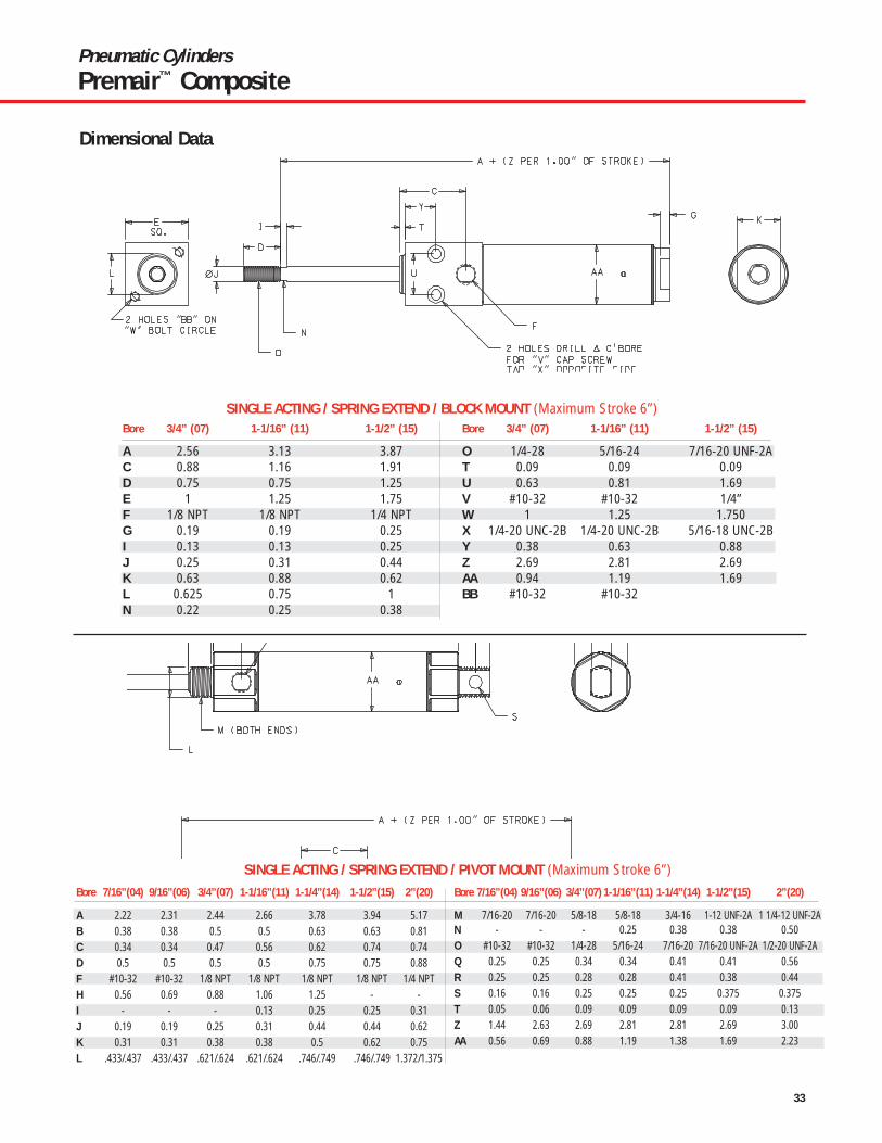
Bore 7/16”(04) 9/16”(06) 3/4”(07) 1-1/16”(11) 1-1/4”(12) 1-1/2”(15) 2”(20)
A 2.13 - 3.22 3.75 - 4.19 -B - - 0.25 0.38 - 0.38 -C 0.72 - 1.34 1.63 - 1.91 -D 0.5 - 0.75 0.75 - 1.25 -E 0.75 - 1 1.25 - 1.75 -F 10-32 - 1/8 NPT 1/8 NPT - 1/4 NPT -G 0.19 - 0.19 0.19 - 0.25 -I - - 0.25 0.25 - 0.25 -J 0.19 - 0.25 0.31 - 0.44 -K 0.38 - 0.63 0.88 - 1.50 -L 0.44 - 0.63 0.75 - 1 -
Bore 7/16”(04) 9/16”(06) 3/4”(07) 1-1/16”(11) 1-1/4”(14) 1-1/2”(15) 2”(20)
N - - 0.22 0.25 - 0.38 -O 10-32 - 1/4-28 5/16-24 - 7/16-20 UNF-2A -T 0.06 - 0.09 0.09 - 0.09 -U 0.44 - 0.63 0.81 - 1.69 -V - - #10-32 #10-32 - 1/4” -W 0.75 - 1.00 1.25 - 1.750 -X #8-32 - 1/4-20 UNC-28 1/4-20 UNC-28 - 5/16-18 UNC-2B -Y 0.25 - 0.38 0.63 - 0.88 -Y1* 0.69 - - - - - -AA 0.56 - 0.88 1.19 - 1.69 -BB #8-32 - #10-32 #10-32 - 1/4-20 UNC-2B -
Bore 7/16”(04) 9/16”(06) 3/4”(07) 1-1/16”(11) 1-1/4”(12) 1-1/2”(15) 2”(20)
A 2.81 2.94 4 4.38 5.56 5.12 6.56B 0.38 0.38 0.5 0.5 0.63 0.63 0.81C 0.34 0.34 0.47 0.56 0.75 0.33 0.74D 0.5 0.5 0.5 0.5 0.75 0.75 0.88F #10-32 #10-32 1/8 NPT 1/8 NPT 1/8 NPT 1/8 NPT 1/4 NPTH 0.56 0.69 0.88 1.06 1.25 - -I - - - 0.13 0.25 0.25 0.31
Bore 7/16”(04) 9/16”(06) 3/4”(07) 1-1/16”(11) 1-1/4”(14) 1-1/2”(15) 2” (20)
J 0.19 0.19 0.25 0.31 0.44 0.44 0.62L .433/.437 .433/.437 .621/.624 .621/.624 .746/.749 .746/.749 1.372/1.375M 7/16-20 7/16-20 5/8-18 5/8-18 3/4-16 1-12 UNF-2A 1 1/4-12 UNF-2AN - - - 0.25 0.38 0.38 0.50O #10-32 #10-32 1/4-28 5/16-24 7/16-20 7/16-20 UNF-2A 1/2-20 UNF-2AT 0.05 0.06 0.09 0.09 0.09 0.09 0.13AA 0.56 0.69 0.88 1.19 1.38 1.69 2.23
DOUBLE ACTING / DOUBLE ROD END ( Maximum Stroke 12”, 6” for 7/16” and 9/16” Bore)
Dimensional Data
DOUBLE ACTING / BLOCK MOUNT ( Maximum Stroke 12”)

29
Pneumatic CylindersPremair™ Composite
*
Bore 7/16”(04) 9/16”(06) 3/4”(07) 1-1/16”(11) 1-1/4”(12) 1-1/2”(15) 2”(20)
A 2.13 2.28 2.97 3.13 4 3.69 4.69B 0.38 0.38 0.5 0.5 0.62 0.63 0.81C 0.34 0.34 0.47 0.56 0.75 0.74 0.74D 0.5 0.5 0.5 0.5 0.75 0.75 0.88F #10-32 #10-32 1/8 NPT 1/8 NPT 1/8 NPT 1/8 NPT 1/4 NPTG 0.19 0.19 0.19 0.19 0.19 0.25 0.31H 0.56 0.69 0.88 1.06 1.25 - -I - - - 0.13 0.25 0.25 0.31
Bore 7/16”(04) 9/16”(06) 3/4”(07) 1-1/16”(11)1-1/4”(14) 1-1/2”(15) 2”(20)
J 0.19 0.19 0.25 0.31 0.44 0.44 0.62K 0.38 0.50 0.62 0.88 0.88 0.62 1.25L .433/.437 .433/.437 .621/.624 .621/.624 .746/.749 .746/.769 1.372/1.375M 7/16-20 7/16-20 5/8-18 5/8-18 3/4-16 1-12 UNF-2A 1 1/4-12 UNF-2AN - - - 0.25 0.38 0.38 0.50O #10-32 #10-32 1/4-28 5/16-24 7/16-20 7/16-20 UNF-2A 1/2-20 UNF-2AT 0.05 0.06 0.09 0.09 0.09 0.09 0.13AA 0.56 0.69 0.88 1.19 1.38 1.69 2.23
DOUBLE ACTING / NOSE MOUNT ( Maximum Stroke 12”)
Bore 7/16”(04) 9/16” (06) 3/4” (07) 1-1/16” (11) 1-1/4” (12) 1-1/2” (15) 2” (20)
A 2.56 2.56 3.75 3.84 4.72 4.38 5.62B 0.38 0.38 0.5 0.5 0.63 0.63 0.81C 0.34 0.34 0.47 0.56 0.62 0.74 0.74D 0.5 0.5 0.5 0.5 0.75 0.75 0.88F #10-32 #10-32 1/8 NPT 1/8 NPT 1/8 NPT 1/8 NPT 1/4 NPTH 0.56 0.69 0.88 1.06 1.25 - -I - - - 0.13 0.25 0.25 0.31J 0.19 0.19 0.25 0.31 0.44 0.44 0.62K 0.31 0.31 0.38 0.38 0.5 0.62 0.75L .433/.437 .433/.437 .621/.624 .621/.624 .746/.749 .746/.749 1.372/1.375
Bore 7/16”(04) 9/16” (06) 3/4” (07)1-1/16” (11)1-1/4” (14) 1-1/2” (15) 2” (20)
M 7/16-20 7/16-20 5/8-18 5/8-18 3/4-16 1-12 UNF-2A 1 1/4-12 UNF-2AN - - - 0.25 0.38 0.38 0.50O #10-32 #10-32 1/4-28 5/16-24 7/16-20 7/16-20 UNF-2A 1/2-20 UNF-2AP 0.44 0.44 0.69 0.63 0.78 0.81 1.03Q 0.25 0.25 0.34 0.34 0.41 0.41 0.56R 0.25 0.25 0.28 0.28 0.41 0.38 0.44S 0.156 0.156 0.25 0.25 0.25 0.375 0.375T 0.05 0.06 0.09 0.09 0.09 0.09 0.13AA 0.56 0.69 0.88 1.19 1.38 1.69 2.23
DOUBLE ACTING / PIVOT MOUNT (Maximum Stroke 32”, 12” for 7/16” and 9/16” Bore)
Dimensional Data

30
Pneumatic CylindersPremair™ Composite
57/16 BORE ONLY
SINGLE ACTING / SPRING RETRACT / NOSE MOUNT (Maximum Stroke 6”)Bore 7/16”(04) 9/16”(06) 3/4”(07) 1-1/16”(11) 1-1/4”(12) 1-1/2”(15) 2”(20)
A 1.31 1.53 1.5 2.06 2.66 2.44 3.29B 0.31 0.38 0.5 0.5 0.63 0.63 0.81C 0.34 0.38 0.47 0.56 0.75 0.74 0.74D 0.5 0.5 0.5 0.5 0.75 0.75 0.88F #10-32 #10-32 1/8 NPT 1/8 NPT 1/8 NPT 1/8 NPT 1/4 NPTG 0.19 0.19 0.19 0.19 0.19 0.25 0.31H 0.56 0.69 0.88 1.06 1.25 - -I - - - 0.13 0.25 0.25 0.31J 0.19 0.19 0.25 0.31 0.44 0.44 0.62
Bore 7/16”(04) 9/16”(06) 3/4”(07) 1-1/16”(11) 1-1/4”(14) 1-1/2”(15) 2”(20)
K 0.38 0.5 0.62 0.88 0.88 0.62 0.75L .433/.437 .433/.437 .621/.624 .621/.624 .746/.749 .746/.749 1.372/1.375M 7/16-20 7/16-20 5/8-18 5/8-18 3/4-16 1-12 UNF-2A 1 1/4-12 UNF-2AN - - - 0.25 0.38 0.38 0.50O #10-32 #10-32 1/4-28 5/16-24 7/16-20 7/16-20 UNF-2A 1/2-20 UNF-2AT 0.05 0.06 0.09 0.09 0.093 0.09 0.13Z 0.94 1.63 1.69 1.56 1.81 1.69 2.00AA 0.56 0.69 0.88 1.19 1.38 1.69 2.23
Bore 7/16”(04) 3/4”(07) 1-1/16”(11) 1-1/2”(15) 2”(20)
A 1.94 2.56 3.13 3.87 -B - 0.25 0.38 - -D 0.5 0.75 0.75 1.25 -E 0.75 1 1.25 1.75 -F #10-32 1/8 NPT 1/8 NPT 1/8 NPT -G 0.19 0.19 0.19 0.25 -I - 0.25 0.25 0.25 -J 0.19 0.25 0.31 0.44 -K 0.38 0.63 0.88 0.62 -L 0.44 0.63 0.75 1 -M - - - - -N - 0.22 0.25 0.38 -O #10-32 1/4-28 5/16-24 7/16-20 UNF-2A -P - - - - -
Bore 7/16”(04) 3/4”(07) 1-1/16”(11) 1-1/2”(15) 2”(20)
Q - - - - -R - - - - -S - - - - -T 0.06 0.09 0.09 0.09 -U 0.44 0.63 0.81 1.69 -V - #10-32 #10-32 1/4” -W 0.75 1.00 1.25 1.750 -X #8-32 1/4-20 UNC-2B 1/4-20 UNC-2B 5/16-18 UNC-2B -Y 0.25 0.38 0.63 0.88 -Y1 0.69 - - - -Z .94 ** 1.69 1.81 1.69 -AA 0.56 0.88 1.19 1.69 -BB #8-32 #10-32 #10-32 - -
* - 7/16” Bore Only ** - Per .500” Stroke (7/16” Bore Only)
SINGLE ACTING / SPRING RETRACT / BLOCK MOUNT (Maximum Stroke 6”)
Dimensional Data

31
Pneumatic CylindersPremair™ Composite
57/16 BORE ONLY*
Kit includes clamp, cradle and stainless steel screw. Switches are designed tonest in cradle, cradle is affixed to cylinder using posilock snap. Switches can befine adjusted in cradle.
Model Number 114406-1114406-2 114406-3 114407-1 114407-2 114407-3 114416-1 114416-2 114416-3Lead Length/Type 1m bare 3m bare Plug 1m bare 3m bare Plug 1m bare 3m bare PlugLead Color Gray Black GreySwitch Type REED PNP(SOURCING) NPN (SINKING)Input Voltage 100 Vdc, 120VAC 4.5V~30 Vdc 4.5V~30 VdcOperating Current 5~40mA, Max. 50mA Max. 50m @30 VDC Max. 50m @ 30 VDCDetecting Distance 2.0 mm 3.0 mm 3.0 mmSensing Area 12mm 5mm 5mmLocation from TipDetecting Width - 2.0 mm 2.0 mmResponse Time 1 mSec. Min. 1 mSec. Min. 1 mSec. Min.LED 5mA Min. Min. 1mA @ 5Vdc (Max. 9mA @ 24 Vdc)LED Color Red Red RedProtection Reverse BatteryShock Vibration MIL-STD-810EEnvironmental IP67 and VL94VO
** - Per .500” Stroke (7/16” Bore Only)
SINGLE ACTING / SPRING RETRACT / PIVOT MOUNT (Maximum Stroke 6”)Bore 7/16”(04) 9/16”(06) 3/4”(07) 1-1/16”(11) 1-1/4”(14) 1-1/2”(15) 2”(20)
A 1.75 1.81 2.28 2.66 3.38 3.12 4.23B 0.31 0.38 0.5 0.5 0.63 0.63 0.81D 0.5 0.5 0.5 0.5 0.75 0.75 0.88F #10-32 #10-32 1/8 NPT 1/8 NPT 1/8 NPT 1/8 NPT 1/4 NPTH 0.56 0.69 0.88 1.06 1.25 - -I - - - 0.13 0.25 0.25 0.31J 0.19 0.19 0.25 0.31 0.44 0.44 0.62K 0.31 0.31 0.38 0.38 0.5 0.62 0.75L .433/.437 .433/.437 .621/.624 .621/.624 .746/.749 .746/.749 1.372/1.375M 7/16-20 7/16-20 5/8-18 5/8-18 3/4-16 1-12 UNF-2A 1 1/4-12 UNF-2A
Bore 7/16”(04) 9/16”(06) 3/4”(07) 1-1/16”(11) 1-1/4”(14) 1-1/2”(15) 2”(20)
N - - - 0.25 0.38 0.38 0.50O #10-32 #10-32 1/4-28 5/16-24 7/16-20 7/16-20 UNF-2A 1/2-20 UNF-2AP 0.44 0.44 0.69 0.63 0.78 0.81 1.03Q 0.25 0.25 0.34 0.34 0.41 0.41 0.56R 0.25 0.19 0.28 0.28 0.41 0.38 0.44S 0.156 0.156 0.25 0.25 0.25 0.375 0.375T 0.05 0.06 0.09 0.09 0.09 0.09 0.13Z 0.94** 1.63 1.69 1.56 1.81 1.69 2AA 0.56 0.69 0.88 1.19 1.38 1.69 2.23
1144XX-X
1144XX-3
114701-XXXBore Size 7/16” 9/16” 3/4” 1-1/16” 1-1/4” 1-1/2” 2”
Model No. 114701-043 114701-056 114701-075 114701-106 114701-125 114701-150 114701-200
NOTE: Plug is 8mm 3 pin PICO Connector
Dimensional Data
Switches (Specifications/Ordering)
Switch Bracket kit

32
Pneumatic CylindersPremair™ Composite
Dimensional Data
Spring Forces
Bore 7/16”(04) 9/16” (06) 3/4” (07) 1-1/16” (11) 1-1/4” (14)1-1/2” (15) 2” (20)
A 1.78 2 2.31 2.38 3.31 3.25 4.23B 0.38 0.38 0.5 0.5 0.63 0.63 0.81C 0.34 0.34 0.47 0.56 0.62 0.74 0.74D 0.5 0.5 0.5 0.5 0.75 0.75 0.88F #10-32 #10-32 1/8 NPT 1/8 NPT 1/8 NPT 1/8 NPT 1/4 NPTG 0.19 0.19 0.19 0.19 0.19 0.25 0.31H 0.63 0.75 0.94 1.19 1.38 - -I - - - 0.13 0.25 0.25 0.31J 0.19 0.19 0.25 0.31 0.44 0.44 0.62
Bore 7/16”(04) 9/16” (06) 3/4” (07)1-1/16” (11)1-1/4” (14) 1-1/2” (15) 2” (20)
K 0.38 0.5 0.38 0.38 0.5 0.62 0.75L .433/.437 .433/.437 .621/.624 .621/.624 .746/.749 .746/.749 1.372/1.375M 7/16-20 7/16-20 5/8-18 5/8-18 3/4-16 1-12 UNF-2A 1 1/4-12UNF-2AN - - - 0.25 0.38 0.38 0.50O #10-32 #10-32 1/4-28 5/16-24 7/16-20 7/16-20 UNF-2A 1/2-20 UNF-2AT 0.05 0.06 0.09 0.09 0.09 0.09 0.13Z 1.44 1.63 2.69 2.81 2.81 2.69 3.00AA 0.56 0.69 0.88 1.19 1.38 1.69 2.23
SINGLE ACTING / SPRING EXTEND / NOSE MOUNT (Maximum Stroke 6”)
Bore Relaxed CompressedSize (lbs.) (lbs.)5/16” .5 17/16” 1 29/16” 2 43/4” 3 67/8” 3 6
1-1/16” 3 61-1/4” 7.5 151-1/2” 7 141-3/4” 11 24
2” 15 30
33
Pneumatic CylindersPremair™ Composite
Bore 3/4” (07) 1-1/16” (11) 1-1/2” (15)
A 2.56 3.13 3.87C 0.88 1.16 1.91D 0.75 0.75 1.25E 1 1.25 1.75F 1/8 NPT 1/8 NPT 1/4 NPTG 0.19 0.19 0.25I 0.13 0.13 0.25J 0.25 0.31 0.44K 0.63 0.88 0.62L 0.625 0.75 1N 0.22 0.25 0.38
Bore 3/4” (07) 1-1/16” (11) 1-1/2” (15)
O 1/4-28 5/16-24 7/16-20 UNF-2AT 0.09 0.09 0.09U 0.63 0.81 1.69V #10-32 #10-32 1/4”W 1 1.25 1.750X 1/4-20 UNC-2B 1/4-20 UNC-2B 5/16-18 UNC-2BY 0.38 0.63 0.88Z 2.69 2.81 2.69AA 0.94 1.19 1.69BB #10-32 #10-32
SINGLE ACTING / SPRING EXTEND / BLOCK MOUNT (Maximum Stroke 6”)
Bore 7/16”(04) 9/16”(06) 3/4”(07) 1-1/16”(11) 1-1/4”(14) 1-1/2”(15) 2”(20)
A 2.22 2.31 2.44 2.66 3.78 3.94 5.17B 0.38 0.38 0.5 0.5 0.63 0.63 0.81C 0.34 0.34 0.47 0.56 0.62 0.74 0.74D 0.5 0.5 0.5 0.5 0.75 0.75 0.88F #10-32 #10-32 1/8 NPT 1/8 NPT 1/8 NPT 1/8 NPT 1/4 NPTH 0.56 0.69 0.88 1.06 1.25 - -I - - - 0.13 0.25 0.25 0.31J 0.19 0.19 0.25 0.31 0.44 0.44 0.62K 0.31 0.31 0.38 0.38 0.5 0.62 0.75L .433/.437 .433/.437 .621/.624 .621/.624 .746/.749 .746/.749 1.372/1.375
Bore 7/16”(04) 9/16”(06) 3/4”(07) 1-1/16”(11) 1-1/4”(14) 1-1/2”(15) 2”(20)
M 7/16-20 7/16-20 5/8-18 5/8-18 3/4-16 1-12 UNF-2A 1 1/4-12 UNF-2AN - - - 0.25 0.38 0.38 0.50O #10-32 #10-32 1/4-28 5/16-24 7/16-20 7/16-20 UNF-2A 1/2-20 UNF-2AQ 0.25 0.25 0.34 0.34 0.41 0.41 0.56R 0.25 0.25 0.28 0.28 0.41 0.38 0.44S 0.16 0.16 0.25 0.25 0.25 0.375 0.375T 0.05 0.06 0.09 0.09 0.09 0.09 0.13Z 1.44 2.63 2.69 2.81 2.81 2.69 3.00AA 0.56 0.69 0.88 1.19 1.38 1.69 2.23
SINGLE ACTING / SPRING EXTEND / PIVOT MOUNT (Maximum Stroke 6”)
Dimensional Data

34
Pneumatic CylindersEconomair®
FeaturesSeries 23, 24, & 28 Economair round cylinders are medium to heavy-duty units that can be installed anywhere that arepairable cylinder is desired. Prelubed, they’re suitable for operation without externally appliedlubrication. Unique endcap retention design provides a concentric assembly, resulting in a servicelife superior to tie rod cylinder construction.
• Cylinder heads are high tensile strength aluminum alloy, retained by a feed ring wire, asimple design that eliminates excess cylinder weight and bulk.
• The barrel I.D. is hard-coated aluminum with a Rockwell C60 hardness. A finish of 16microinches or better insures low friction and smooth operation.
• Piston rod is ground and polished, hard-chrome plated steel for minimum friction andmaximum packing life. Optional 303 stainless steel is excellent for corrosion resistanceand washdown applications (303 stainless steel is standard on 1-1/8-inch bore cylinders).
• Adjustable cushions provide excellent control of cylinder deceleration. Full rangeadjustability (except fixed cushions on 1-1/8-inch bore).
• High grade, self-lubricating bronze rod bearing reduces friction and promotes smoothoperation.
• Piston seal selection insures job-matched performance - Buna N O-ring, Low FrictionU-cup and self-lubricating packings available.
• Wear compensating rod wiper protects internal seals and parts from dirt, grit and debris.
• NPTF dry seal pipe threads on ports.
• Optional self-lubricating U-cup seals reduce drag and promote extra cylinder life.
• Cylinder is repairable so instead of buying complete new units, repair kits can be used.
U-cup and Magnetic Piston Options
Performance SpecificationsBore Sizes: 1-1/8", 1-1/2", 2", 2-1/2", 3" and 4"Maximum Output Force: 2,513 pounds (4-inch bore).Air Pressure: To 200 p.s.i. (14 bar).
May be operated hydraulically (200 p.s.i., nonshock).Operating Temperature Range: 0° to 180° F (-18° to 82° C).Seals: Viton seals available for high heat applications. Consult factory.Notes: Wide range of mounting styles and attachable mounting
hardware/ accessories allows cylinders to be applied in nearlyany pneumatic application.

35
STROKE LENGTHWHOLE INCHES FRACTIONS
00 = 0 in 0 = 0 in01 = 1 in 1 = 1/8 in02 = 2 in 2 = 1/4 in03 = 3 in 3 = 3/8 in04 = 4 in 4 = 1/2 in05 = 5 in 5 = 5/8 in06 = 6 in 6 = 3/4 in◊ ◊ 7 = 7/8 into to 99 99 in
Pneumatic CylindersEconomair®
OrderingSeries 23, 24, & 28
BORE SIZE18 1-1/8 in 15 1-1/2 in20 2 in25 2-1/2 in30 3 in40 4 in
CYLINDER TYPE1 Double Acting, Rear Tang5 Double Acting, No Rear Tang2 Double Acting, Double Rod
NOTE: Not Available in Series 28
Economair mounts must be orderedseparately, see below.
PACKING0 O-Ring, Nitrile2 O-Ring, Low Friction3 O-Ring, Viton4 Lip, Nitrile (pneumatic)5 Lip, Self-Lubricating (low friction)6 Lip, Viton
OPTIONS09 Standard Rod89 303 Stainless Steel Rod
2X XX - X X X9 - XXXInclude dashes ( - ). The dashes are significant.
SERIES NO.
23 Noncushioned24 Cushioned, Both Ends28 Magnetic Piston, Cushioned Both Ends
NOTE: 1-1/8 inch bore not available
These packings add one inchto cylinder length.
Viton not available in Series 28
Note: Highlighted selections denote most popular models.
Not available in Series 28
Standard on 1-1/8" bore cylinder.
Flange Mount
Mounting NutTrunnion Rod Clevis & Clevis Bracket
L-Mount
(1" Increments, 1" through 10" plus1 1/2", 2 1/2" and 3 1/2")
MountsCylinder Bore (Inches)
1-1/8 1-1/2 2 2-1/2 3 4L-Mount (2 qty.) 20533 20534 20534 20535 20535 20536Flange Mount 20537 20538 20538 20539 20539 20540Clevis Bracket 20546 20547 20547 20548 20548 20549Mounting Nut (2 qty.) 20529 20530 20530 20531 20531 20532Trunnion 20524 20556 20557 20558 20559 20560Aluminum Rod Clevis – 20542 20543 20544 20544 20545Steel Rod Clevis 20541 115906 115907 115908 115908 115909
Note: Order cylinder, rod clevis and clevis bracket separately.Every Economair Cylinder includes rod nut.Trunnion Mount does not include pillow block.

36
Pneumatic CylindersEconomair® - Dimensional Data
Dimensional DataSeries 23, 24, & 28
L-Type
Flange
Clevis Bracket
Mounting Nut
A
A/2C D
B E
E
FH
PE
QD
N
P/2
P
P/2
T T
UD
S
G
T/2
U
T/2
R
L
M
K
TrunnionAluminum Rod Clevis
TD
TG
TE
TFTA
TB 1/16
TC
ZZ
ZJ TH
Y
X
X
WV
ZZ TM
TN
WTK
ZY THTL
Steel Rod Clevis
Cylinder Bore (Inches)Reference 1-1/8 1-1/2 2 2-1/2 3 4Rod dia. 0.38 0.50 0.63 0.75 0.75 1.00
A 1.625 3.00 3.00 4.00 4.00 5.00B 1.281 1.50 1.50 2.00 2.00 2.625C 1.00 1.688 1.688 2.25 2.25 3.00
D-dia* .250 .250 .250 .375 .375 .438E .250 .313 .313 .375 .375 .438F .625 .906 .906 1.219 1.219 1.469G .375 .500 .500 .625 .625 .750H 1.00 1.531 1.531 2.094 2.094 2.531J .750 1.00 1.00 1.25 1.25 1.188K .375 .469 .469 .781 .781 .781
L-HEX 1.0625 1.438 1.438 2.0625 2.0625 2.50M-dia. 1.25 1.75 1.75 2.438 2.438 2.938
N 2.00 2.50 2.50 3.375 3.375 4.00P 2.50 3.25 3.25 4.50 4.50 5.188Q .688 .594 .594 .719 .719 .844R 1.219 1.750 1.750 2.375 2.375 3.00S .313 .313 .313 .375 .375 .438T 2.250 3.00 3.00 4.00 4.00 5.00U 1.75 2.25 2.25 3.00 3.00 3.75V 1.75 2.25 2.25 2.688 2.688 3.375W 1.406 1.75 1.75 2.0625 2.0625 2.625X .750 1.00 1.00 1.25 1.25 1.50
Y-dia.* .250 .3125 .3125 .438 .4375 .625Z .656 .688 .688 .875 .875 1.063ZZ .3125 .375 .375 .500 .500 .625TA 3.125 4.125 4.125 5.375 5.625 7.125TB 2.25 3.00 3.00 3.75 4.25 5.50
TC-dia. .438 .500 .500 .750 .750 .750TD 2.00 2.625 3.125 4.00 4.50 5.75TE .875 1.125 1.375 1.875 2.125 2.688TF .750 1.250 1.250 1.50 1.50 1.50
TG-dia.* .250 .3125 .3125 .4375 .4375 .500TH-Thd. 3/8-16 1/2-13 5/8-11 3/4-10 3/4-10 1-8
TK – 2.0625 2.0625 2.50 2.50 3.25TL – .875 .875 1.00 1.00 1.325TM – 1.0625 1.0625 1.438 1.438 1.938TN – 1.813 1.00 1.813 1.813 1.50
*Bolt or pin diameter

37
Pneumatic CylindersEconomair® - Dimensional Data
Dimensional DataSeries 23, 24, & 28 (Double Acting with Tang)
(Double Acting, No Tang)
(Double Acting, Double Ended)
NN Rod Flats
GG
KK
CC BB
EE
EE SS
PP
DD
JJ
GG
TT
MM
CB
DD
HH
FFUU
JJR
Stroke + OO
AA = Double acting with O-ring or low friction packing.LP = Double acting with U cup packing.
Stroke + AAStroke + LP
RR
AA = Double acting with O-ring or low friction packing.LP = Double acting with U cup packing.
NN Rod Flats
GG
FACC
CB
EELL
EE
UU
RT
DD
FF
BB
KK
RJJ
HH
Stroke + AAStroke + LP
Stroke + AAStroke + LP Stroke + CBCB

38
Pneumatic CylindersEconomair® - Dimensional Data
Dimensional DataSeries 23, 24, & 28
Dimensional Cylinder Bore (Inches)Reference 1-1/8 1-1/2 2 2-1/2 3 4Rod Diameter .38 .50 .63 .75 .75 1.00 Stroke Factor AA* 2.031 2.625 2.625 2.875 2.875 4.00Stroke Factor LP** 3.031 3.625 3.625 3.875 3.875 5.00
BB .750 1.00 1.00 1.250 1.250 1.250CB 1.750 2.438 2.438 2.938 2.938 3.500CC 1.00 1.438 1.438 1.688 1.688 2.250DD .125 .219 .219 .344 .344 .406EE .422 .516 .516 .563 .563 .813FA .781 1.156 1.156 1.375 1.375 1.750
FFs .875 1.250 1.250 1.50 1.50 1.875(± .002) GG .748 1.057 1.057 1.432 1.432 1.777
(UNC-2A) HH 3/8-16 1/2-13 5/8-11 3/4-10 3/4-10 1-8JJ 3/4-16 1-1/16-18 1-1/16-18 1-3/8-12 1-3/8-12 1-3/4-12
UNF-2A UNEF-2A UNEF-2A UNF-2A UNF-2A UN-2AKK .313 .500 .500 .500 .500 .500
(NPTF) LL 1/8-27 1/4-18 1/4-18 3/8-18 3/8-18 1/2-14MM 1.375 1.750 2.250 2.750 3.250 4.250NN .313 .406 .500 .625 .625 .875OO 3.594 4.688 4.688 5.688 5.688 7.063PP .688 .875 .875 1.375 1.375 1.438QQ .375 .500 .500 .625 .625 .750
(RAD.) R .016 .016 .016 .094 .094 .094RR .250 .313 .313 .438 .438 .500RT – .172 – .438 .438 .438SS .969 1.25 1.25 2.00 2.00 2.188TT – .438 .438 .438 .438 .438UU – .500 .500 .500 .625 .625
* Double acting with O-ring or low friction packing** Double acting with U-cup packings FF shows total thread, including run out.

39
Pneumatic CylindersEconomair®
Model Number 119581-1 119581-2 119581-3 119582-1 119582-2 119582-3 119583-1 119583-2 119583-3Lead Length/Type 1m bare 3m bare Plug 1m bare 3m bare Plug 1m bare 3m bare PlugLead Color Black Grey BlackSwitch Type REED PNP(SOURCING) NPN (SINKING)Input Voltage 100 VDC, 125 VAC Max. 10 - 30 VDC 5 - 30 VDC
– – 5 - 100mA @ 5VOperating Current 300mA (150mA Inductive) 7 - 100mA @ 12V 10 - 200mA @ 12V
– 14 - 200mA @ 24V 20 - 200mA @ 24VDetecting Distance 2.5 mm 1.5 mm 1.5 mmDetecting Width – 3.0 mm 3.0 mmResponse Time 1 mSec. Min. – –LED Function 18mA Min. 1mA Min. 1mA Min.
Switches (Specifications / Ordering)Switch
Switch Mounting Brackets
Note: Order bracket and switch separately.
Bore Model Number1-1/8" 119897-181-1/2" 119897-152" 119897-202-1/2" 119897-253" 119897-304" 119897-40
(Switch Bracket)
Technical Information:1. Do not exceed specification, permanent damage to the sensor may
occur.
2. For reed switch type sensors, polarity must be observed for theproper functioning of LED. Connect the brown wire in series with loadpositive (+) and the blue wire to negative (-) or power source space.If the polarity is reversed, reed switch remains functional but LED willremain in “OFF” state.
3. For solid-state type sensors, polarity must also be observed. Connectbrown wire to the positive (+) and the blue to the negative (-) of DCpower source. The black wire must connect to the load ONLY. If theblack wire is accidentally connected to the power source, permanentdamage to the sensor may occur.
4. An external protection circuit may be required if the reed switch isused with inductive load, such as relay or solenoid. For DC inductiveload, attach an external diode parallel to the load and use R -C circuitparallel with AC inductive load.
5. Keep sensors away from stray magnetic field to prevent malfunctions.
6. When using reed switch with capacitive load or if the lead wire lengthexceeds 10-meter, and inductor must be installed in series with thesensor to prevent damage (Sticking effect).

40
Pneumatic CylindersRod Alignment Cylinders
Features• Slide applications no longer require costly precision cylinder machining for
mounting fixed or rigid guide.
• Friction due to misalignment is eliminated, increasing cylinder efficiency.
• An angular error of 2° and 1/16 inch lateral misalignment on push and pullstroke is compensated.
• Cylinder and component wear is reduced, providing increased reliability.
• Field alignment problems are rectified.
• All components are heat treated for improved corrosion resistance, wearresistance, and fatigue properties.
Dimensional Data
Ordering
WORK SHAFT(PRECISION GUIDED)
BEARINGS
SUPPORT BASE
SUPPORT BASE(ANGULAR)
LATERAL
“H”ACROSS
FLATS
GACROSSFLATSB
C
E E
AA
“F” DIA. OF SHANK
1/16 RADIAL FLOAT2° SPHERICAL MOTION
D
Dimensions Max. PullCoupler At YieldsNumber A B C D E F G H (Pounds)118683 3/8-16 .875 1.25 .25 .625 .313 .313 .75 5,000118684 7/16-20 1.25 2.00 .50 .75 .625 .50 1.00 10,000118685 1/2-20 1.25 2.00 .50 .75 .625 .50 1.00 14,000118686 1/2-13 1.25 2.00 .50 .75 .625 .50 1.00 14,000118687 5/8-18 1.25 2.00 .50 .75 .625 .50 1.00 19,000118688 3/4-16 1.75 2.31 .50 1.125 .97 .813 1.50 34,000118689 3/4-10 1.75 2.31 .50 1.125 .97 .813 1.50 34,000118690 7/8-14 1.75 2.31 .50 1.125 .97 .813 1.50 39,000118691 1-14 2.50 2.94 .50 1.625 1.375 1.16 2.25 64,000118692 1-8 2.50 2.94 .50 1.625 1.375 1.16 2.25 64,000118693 1-1/4-12 2.50 2.94 .50 1.625 1.375 1.16 2.25 78,000118694 1-3/8-12 2.50 2.94 .50 1.625 1.375 1.16 2.25 78,000118695 1-1/2-12 3.25 4.375 .812 2.25 1.375 1.50 3.00 134,000
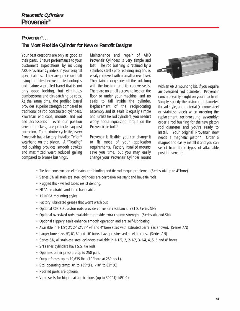
41
Pneumatic CylindersProvenair®
• Tie bolt construction eliminates rod binding and tie rod torque problems. (Series AN up to 4" bore)
• Series SN all stainless steel cylinders are corrosion resistant and have tie rods.
• Rugged thick walled tubes resist denting.
• NFPA repairable and interchangeable.
• 15 NFPA mounting styles.
• Factory lubricated grease that won’t wash out.
• Optional 303 S.S. piston rods provide corrosion resistance. (STD. Series SN)
• Optional oversized rods available to provide extra column strength. (Series AN and SN)
• Optional slippery seals enhance smooth operation and are self-lubricating.
• Available in 1-1/2", 2", 2-1/2", 3-1/4" and 4" bore sizes with extruded barrel (as shown). (Series AN)
• Larger bore sizes 5", 6", 8" and 10" bores have prestressed steel tie rods. (Series AN)
• Series SN, all stainless steel cylinders available in 1-1/2, 2, 2-1/2, 3-1/4, 4, 5, 6 and 8" bores.
• SN series cylinders have S.S. tie rods.
• Operates on air pressure up to 250 p.s.i.
• Output forces up to 19,635 lbs. (10" bore at 250 p.s.i.).
• Std. operating temp: 0° to 185°(F), -18° to 82° (C).
• Rotated ports are optional.
• Viton seals for high heat applications (up to 300° F, 149° C)
Your best creations are only as good astheir parts. Ensure performance to yourcustomer’s expectations by includingARO Provenair Cylinders in your originalspecifications. They are precision builtusing the latest extrusion technologiesand feature a profiled barrel that is notonly good looking, but eliminatescumbersome and dirt-catching tie rods.At the same time, the profiled barrelprovides superior strength compared totraditional tie rod constructed cylinders.Provenair end caps, mounts, and rodend accessories - even our positionsensor brackets, are protected againstcorrosion. To maximize cycle life, everyProvenair has a factory-installed Teflon®
wearband on the piston. A “Floating”rod bushing provides smooth strokesand maximized wear; reduced gallingcompared to bronze bushings.
Maintenance and repair of AROProvenair Cylinders is very simple andfast. The rod bushing is retained by astainless steel spiro retaining ring and iseasily removed with a small screwdriver.The retaining ring slides off the rod alongwith the bushing and its captive seals.There are no small screws to lose on thefloor or under your machine, and noseals to fall inside the cylinder.Replacement of the reciprocatingassembly and its seals is equally simpleand, unlike tie rod cylinders, you needn’tworry about equalizing torque on theProvenair tie bolts!
Provenair is flexible, you can change itto fit most of your applicationrequirements. Factory installed mountssave you time, but you may easilychange your Provenair Cylinder mount
with an ARO mounting kit. If you requirean oversized rod diameter, Provenairconverts easily - right on your machine!Simply specify the piston rod diameter,thread style, and material (chrome steelor stainless steel) when ordering thereplacement reciprocating assembly;order a rod bushing for the new pistonrod diameter and you’re ready to install. Your original Provenair nowneeds a magnetic piston? Order amagnet and easily install it and you canselect from three types of attachableposition sensors.
Provenair®...The Most Flexible Cylinder for New or Retrofit Designs

42
Pneumatic CylindersProvenair®
“GripRidge” gives a better bracketfastening surface. Brackets and
switches stay-put.
End caps and mounts resistcommon coolants, cleaners,
lubricants and corrosion.
Retained cushionadjustment needles
Lightweight aluminum bodyresists dents.
Performance SpecificationsAluminum NFPA InterchangeableBore sizes: 1-1/2", 2", 2-1/2", 3-1/4", 4", 5", 6", 8" and 10"
Seals: Buna-N, Viton or Slippery (Aluminum alloy piston with lip-type seals)
Barrel: Profiled Extrusion (5", 6", 8" and 10" have tie rods.) (Patented)
Bushings: “Floating" Rod bushings for low friction, superior wear and side load resistance
Switches: Metal Jacketed
Piston Rods: Chrome plated ground and polished high tensile steel
Options: Optional Piston Magnet
Double Rod End
303 S.S. Piston Rods
Studded male rods for 50% stronger threads than cold rolled thread rod ends
Stainless Steel NFPA InterchangeableBore sizes: 1-1/2", 2", 2-1/2", 3-1/4", 4", 5", 6", and 8"
Rod Bushing: Bronze
Rod Wiper: Teflon®
External Components: 303/304 – End caps, tie rods, piston rods, mounts (barrel is 316)
Mounting Styles: 15 NFPA
Options: Optional adjustable cushions
Piston Magnet
Viton Seals (Wiper Teflon)
Double rod ends

43
Pneumatic CylindersProvenair®
Determine portlocation lookingat rod end ofcylinder.
OrderingSeries AN (1-1/2’ thru 10" Bore)
A H1, C1 (Std.)B H1, C2C H1, C3D H1, C4
F H2, C1G H2, C2H H2, C3J H2, C4
X No CushionsB Cushion Both Ends
H Cushion Head End (Rod End)C Cushion Cap End
B Buna-NV VitonS Slippery
G Buna-N + Magnetic PistonH Viton + Magnetic PistonJ Slippery + Magnetic Piston
A Chrome, Std Male (KK1)B Chrome, Intermed. Male(KK2)C Chrome, Full Male (CC)D Chrome, Female (KK1)F Chrome, No ThreadsG S.S., Standard Male (KK1)H S.S., Intermediate Male (KK2)J S.S., Full Male (CC)
K S.S., Female (KK1)L S.S., No Threads1 KK1 Chrome, Studded2 KK2 Chrome, Studded3 CC Chrome, Studded4 KK1 SS, Studded5 KK2 SS, Studded6 CC SS, Studded
K 5/8" Note: Available in 1-1/2", 2" and 2-1/2" bores only.M 1" Note: Available in 2", 2-1/2", 3-1/4", 4" and 5" bores only.P 1 3/8" Note: Available in 3-1/4", 4", 5", 6" and 8" bores only.Q 1 3/4" Note: Available in 6", 8" and 10" bores only.S 2" Note: Available in 10" bores only.
Q 1- 1/2"S 2"T 2- 1/2"
W 3-1/4"4 4"5 5"
6 6"8 8"Y 10"
ACTUATORSAluminum actuators begin with A
SERIES (NFPA)All Provenair Cylinders are Series N
SEALS
CUSHIONSPORT LOCATION
(MS4 mounts: Port locations other than “A”, callfactory. Trunnion mounts: ports “A” or “C” only.)
MOUNT
(8" and 10" Bore ME3, ME4)(Mounts must be factory installedon 5", 6", 8" and 10" Bore)
0 = 0 in1 = 1/8 in2 = 1/4 in3 = 3/8 in4 = 1/2 in5 = 5/8 in6 = 3/4 in7 = 7/8 in
Include dashes ( - ). Dashes are significant.
ROD DIAMETER
ROD STYLE
BORE SIZE Note: 5", 6", 8" & 10" bores have tie rods.
STROKE
Whole Inches
Fractions
N X X X X X X X X X X XA
Note:Maximum stroke 997/8", for longer strokesconsult factory. Strokelengths 20" and longermay require stop tubes,see page 7.
4
3
2
1
All mounts availablethrough 8" Bore except:* 1 1/2" - 4" Bore Only** Available 1 1/2" - 10" Bore
A MS1B MS4**C MP1**D MP2**F MF1/ME3**H MF2/ME4**K MP4*L MS7*M MT2
P MT1Q MX1T MX2U MX3X No Mount1 FMB*2 FMC*3 FMH*4 FMB/MS4*
Note: Highlighted selections denotes most popular models.
Aluminum NFPA
TYPEA Double Acting, Single RodB Double Acting, Double Rod
00 = 0 in01 = 1 in02 = 2 in03 = 3 in04 = 4 in05 = 5 in06 = 6 in◊ ◊to to99 = 99 in

44
00 = 0 in01 = 1 in02 = 2 in03 = 3 in04 = 4 in05 = 5 in06 = 6 in◊ ◊to to99 = 99 in
Pneumatic CylindersProvenair®
OrderingSeries SN (1-1/2’ thru 8" Bore) NOTE: All SN Series Cylinders have tie rods.
A H1, C1 (Std.)B H1, C2C H1, C3D H1, C4
F H2, C1G H2, C2H H2, C3J H2, C4
X No CushionsB Cushion Both Ends
H Cushion Head End (Rod End)C Cushion Cap End
B Buna-NV VitonS Slippery
G Buna-N + Magnetic PistonH Viton + Magnetic PistonJ Slippery + Magnetic Piston
G S.S., Standard Male (KK1)H S.S., Intermediate Male(KK2)
J S.S., Full Male (CC)K S.S., Female (KK1)L S.S., No Threads
K 5/8" Note: Available in 1-1/2", 2" and 2-1/2" bores only.M 1" Note: Available in 2", 2-1/2", 3-1/4", 4" and 5" bores only.P 1 3/8" Note: Available in 3-1/4", 4", 5", 6" and 8" bores only.Q 1 3/4" Note: Available in 6" and 8" bores only.
Q 1- 1/2"S 2"T 2- 1/2"
W 3-1/4"4 4"5 5"
6 6"8 8"
TYPEA Double Acting, Single RodB Double Acting, Double Rod Note: Not available in 8" bore.
ACTUATORSStainless Steel actuators begin with S
SERIES (NFPA)All Provenair Cylinders are Series N
SEALS
CUSHIONS
PORT LOCATION
(MS4 mounts: Port locations otherthan “A”, call factory. Trunnionmounts: ports “A” or “C” only.)
MOUNT
(8" Bore ME3, ME4) (Mounts must be factory installed.)
0 = 0 in1 = 1/8 in2 = 1/4 in3 = 3/8 in4 = 1/2 in5 = 5/8 in6 = 3/4 in7 = 7/8 in
Include dashes ( - ). Dashes are significant.
ROD DIAMETER
ROD STYLE
BORE SIZE
STROKE
Whole Inches
Fractions
N X X X X X X X X X X XS
Note:Maximum stroke 997/8", for longer strokesconsult factory. Strokelengths 20" and longermay require stop tubes,see page 7.
4
3
2
1Determine portlocation lookingat rod end ofcylinder.
* 1 1/2" - 6" Bore Only** 1 1/2" - 4" Bore Only
B MS4**C MP1**F MF1/ME3**H MF2/ME4**K MP4*M MT2
P MT1Q MX1T MX2U MX3X No Mount
Note: Teflon Wiper Std.
NOTE: S.S. Cylinders are made to order, contact factory for lead time.
Stainless Steel NFPA

45
Pneumatic CylindersProvenair®
Attachable Mounting Kits for Series ANSeries AN (1-1/2" Thru 4" Bore)Mounting Kits with Long ScrewsMount styles B (MS4) and X (No mounts) use mounting kits with long screws to attach through cap into barrel of cylinders.
Mount K
MP4 Detachable Eye
MP2 Detachable Clevis
MP1 Fixed Clevis
Mount C
Mount D
Mount M
MT2 Cap Trunnion MT1 Head Trunnion
4
3
2
1
Determine portlocation looking atrod end of cylinder.
Factory Installed Mounts
Note: Not all mounts are available on stainless steel models.
Mount P
Mounting Kits with Short ScrewsMount styles 1 (FMB), 2 (FMC) and 3 (FMH) use mounting kits with short screws to attach to female sleeve bolts.
1 1/2" 2" 2 1/2" 3 1/4" 4"MS7 Side End Lugs (Steel) 119618 119619 119620 119621 119622MF1 Rect. Flange (Steel) 119633 119634 119635 119636 119637MF2 Rect. Flange (Steel) 119646 119647 119648 119649 119650
MP2 HD Clevis (Iron) * 119623 119624 119625 119626 119627MP4 HD Eye (Iron) 119628 119629 119630 119631 119632
MS2 Side Lugs (Alum.) 119638 119639 119640 119641 119642MP1 Fixed Clevis (Alum.) * 119796 119797 119798 119799 119800
Above kits Include all necessary hardware to complete mounting to Provenair cylinders. AN Series only. *Pivot pin included in kit. (Kits not available for 5",6",8", or 10" Bores) (Kits not available for SN Models)
MX1, 2 or 3 Tie Rod Extensions 117822-1 117822-2 117822-2 117822-3 117822-3MX1 requires two tie rod extension bolt kits (four extension studs per kit). Extension bolts can only be used in femaleretaining bolt mounts: Use mounts 1, 2, 3 or contact factory for conversion kits.
1 1/2" 2" 2 1/2" 3 1/4" 4"MS7 Side End Lugs (Steel) 115277 115278 115279 115280 115281MP2 HD Clevis (Iron) * 118696 118697 118698 118699 118700MP4 HD Eye (Iron) 118701 118702 118703 118704 118705MF1, MF2 Flange (Steel) 115282 115283 115284 115285 115286MP1 Fixed Clevis (Alum.) * 115477 115478 115480 115481MP2 Det. Clevis (Alum.) * 115287 115288 115289 115290 115291MP4 Det. Clevis (Alum) * 115292 115293 115294 115295 115296MT1 Head Trunnion (Alum.) 116357 116358 116361MT2 Head Trunnion (Alum.) 116357 116358 116361

46
Pneumatic CylindersProvenair® - Dimensional Data
Mounting DataSeries AN, SN (1-1/2" Thru 10" Bore)Factory Installed Mounts
Mount T Mount U
Mount A
Mount FMount H
Mount 1 Mount 2 Mount 3
Mount Q
MF1 Head Rec. FlangeME4 8" Bore ME3 8" BoreMF2 Cap. Rec. Flange
MX3 Head Ext. Tie RodMX1 Cap and Head Ext. Tie Rod
MS1 Side End Angle
MX2 Cap Ext. Tie Rod
FMB Female retainingbolts, Both Ends
FMC Femaleretaining bolts,Cap
FMH Female retainingbolts, Head
Mount B
MS4 Side Tapped
Note: Not all mounts are available on stainless steel models (Series SN)
Note: Mounts H & F 8" and 10" bore cylinders use oversized end cap asshown (ME3 or ME4). A steel rectangular flange plate is used for allMF1 or MF2 (1 1/2 thru 6" bore).

47
Pneumatic CylindersProvenair® - Dimensional Data
Double Rod End MS4MOUNT B
ZM + (2x Stroke)
ZL + StrokePA + Stroke
SN + Stroke
LD + Stroke WF + StrokeG
NT ThreadTK Depth
Dimensional DataSeries AN , SN (Rod End)
Series AN , SN (With Standard Rod)
D Flats
B
A
CV
MM
NA
KK1, KK2 orCC Thread
D Flats
B
CV
MM
NA
KK1 ThreadA Depth
KK1 THD. A DEPTH
ROD DIA. MM
KK or CC
A
VC
F
Series AN, SN Bore Sizes 1-1/2", 2", 2-1/2", 3-1/4", 4"
Series AN Bore Sizes 5", 6", 8", 10"Series SN all Bore Sizes
BUSHING DIA. B
Es
t
Side Tapped MS4MOUNT B
Rect. Flange – Head-MF1, Cap-MF2MOUNT F & H (1 1/2" - 4" BORE ONLY)
Head Trunnion MT1Cap Trunnion MT2
MOUNT M & P
Side Lug MS2
MMNA
KK1 Thread
B
Y
XTG J
LB + Stroke
SN + Stroke
P + StrokeEE NPTF
ZB + Stroke
NT ThreadTK Depth
FFW
WF
ZF + StrokeZB + Stroke
1
UTXG
XJ+Stroke
1
TFFB, 4 PL.
E
UF
R
STTSUS
XS
SB, 4PL
Stroke + SS
RT Thread RC Depth
(Female retainingbolts either end)
R
R
BC
E
TN
Rod End Dimensions for 1-1/2" – 10" Bore SizesCylinder Bore (Inches)
1-1/2, 2, 2-1/2 2, 2-1/2 3-1/4, 4 3-1/4, 4 5 5, 6, 8 6, 8, 10 10Rod Diameter (Inches) 5/8 1 1 1-3/8 1 1-3/8 1-3/4 2KK1 THD. ( M OR F) 7/16" -20 3/4"-16 3/4"-16 1"-14 3/4"-16 1"-14 1-1/4"-12 1-1/2"-12KK2 THD. (MALE) 1/2"-20 7/8"-14 7/8"-14 1-1/4"-12 7/8"-14 1-1/4"-12 1-1/2"-12 1-3/4"-12CC (MALE) 5/8"-18 1"-14 1"-14 1-3/8"-12 1"-14 1-3/8"-12 1-3/4"-12 2"-12A .75 1.13 1.13 1.63 1.13 1.63 2.00 2.25B 1.13 1.50 1.50 1.50 1.50 2.00 2.38 2.38C .34 .62 .48 .60 .50 .63 .75 .88D .50 .88 .88 .81 .81 1.13 1.50 1.75F .325 .325 .625 .625 .625 .625 .625 .75MM .625 1.00 1.00 1.00 1.00 1.375 1.75 2.00V .66 .75 .89 1.02 .25 .38 .38 * .38
– – – – – – * (.50 on10")Selection of oversize piston rod affects the following dimensions: ZB, ZC, ZD, ZE, ZF, ZL, ZM, XC, XD, XE, XG, XJ,XS, XT, V, W, WF, C, V, LA. See rod end dimensions.
Dimensional Information see page 48

48
Pneumatic CylindersProvenair® - Dimensional Data
Dimensional DataSeries AN, SN (1-1/2" Thru 4" Bore w/standard rod)
MEETING THESTANDARDS. ARO ProvenairCylindersmeet NFPAstandards.Use valvesthat meet thehighest standards – AROAlpha and Genesis Valves. Alpha valves areavailable in body ported and sub-baseconfigurations. Genesis valves are availablein sub-base configuration only and haveconvenient “plug-into-the-base” electronics.
Cylinder Bore (Inches)1-1/2 2 2-1/2 3-1/4 4
B 1.13 1.13 1.13 1.50 1.50BC 2.02 2.60 3.10 3.90 4.70E 2.00 2.50 3.00 3.75 4.50EE 3/8-18 3/8-18 3/8-18 1/2-14 1/2-14F .38 .38 .38 .63 .63FB .31 .38 .38 .44 .44G 1.44 1.44 1.44 1.69 1.69J .94 .94 .94 1.19 1.19KK1 (thread) 7/16-20 7/16-20 7/16-20 3/4-16 3/4-16LB 3.62 3.62 3.75 4.25 4.25LD 4.12 4.12 4.25 4.75 4.75MM (rod dia.) 5/8 5/8 5/8 1.00 1.00NA .59 .59 .59 .97 .97NT 1/4-20 5/16-18 3/8-16 1/2-13 1/2-13P 2.25 2.25 2.38 2.62 2.62PA 2.75 2.75 2.88 3.12 3.12R 1.43 1.84 2.19 2.76 3.32RC .41 .538 .41 .599 .44RT 1/4-28 5/16-24 5/16-24 3/8-24 3/8-24SB .38 .38 .38 .50 .50SN 2.25 2.25 2.38 2.63 2.63SS 2.88 2.88 3.00 3.25 3.25ST .56 .69 .81 1.00 1.19SX .34 .34 .34 .47 .47SY1 1.34 1.53 1.53 2.13 2.19SY2 .94 1.13 1.13 1.50 1.56TF 2.75 3.38 3.88 4.69 5.44TK .38 .43 .69 .75 .75TN .63 .88 1.25 1.50 2.06TS 2.75 3.25 3.75 4.75 5.50UF 3.38 4.13 4.63 5.50 6.25US 3.50 3.69 4.50 5.75 6.50UT 4.00 4.50 5.00 5.75 6.50W .66 .66 .66 .75 .75WF* 1.00 1.00 1.00 1.38 1.38XG* 1.75 1.75 1.75 2.25 2.25XJ* 4.12 4.12 4.25 5.00 5.00XS* 1.38 1.38 1.38 1.88 1.88XT* 1.94 1.94 1.94 2.44 2.44Y* 1.94 1.94 1.94 2.44 2.44ZB* 4.63 4.63 4.75 5.63 5.63ZF* 5.00 5.00 5.12 6.25 6.25ZL* 5.12 5.12 5.25 6.12 6.12ZM* 6.15 6.15 6.27 7.52 7.52
* Oversize piston rod option affects these dimensions.See rod end dimensions.

49
Pneumatic CylindersProvenair® - Dimensional Data
Dimensional DataSeries AN, SN (1-1/2" Thru 10" Bore w/standard rod)
Side End Lugs MS7MOUNT L
Angle Mount MS1MOUNT A
Detachable Eye MP4MOUNT K
Detachable Clevis MP2MOUNT D (AN Series only)
Tie Rod MountsMX1 Extended Both Ends MX3 Extended Head End
MOUNT Q, T & U
ZE + Stroke
SE + StrokeEQ EQ
ET
ET
EE
REB, 4 Pl.
WLEL
XE + StrokeZB + Stroke
WL
ZD + Stroke
XD + Stroke
ZC + Stroke
ZD + Stroke
XD + Stroke
ZB + Stroke
XC + Stroke
M
ML
M
CD
CD
CD
LR
LR
LR
CW CB
CW
CW
BB BB R
RDD
CB
EW
MR
MR
MR
FFL
F
FFL
SA + Stroke
AB,HOLE (6)
S
AH
AO.188
AO
XA + Stroke
AL
W
E
s
t
(Female retainingbolts either end)
MOUNTS 1,2,3,4
E
Fixed Clevis MP1MOUNT C
Dimensional Data Series AN (1-1/2" Thru 4" Bore w/standard rod)
RT Thread RC Depth
Cylinder Bore (Inches)1-1/2 2 2-1/2 3-1/4 4
AB .38 .38 .38 .50 .50AH 1.18 1.44 1.62 1.94 2.25AL 1.00 1.00 1.00 1.25 1.25AO .38 .38 .38 .50 .50BB 1.00 1.13 1.13 1.38 1.38CB .75 .75 .75 1.25 1.25CD .50 .50 .50 .75 .75CW .50 .50 .50 .63 .63DD 1/4-28 5/16-24 5/16-24 3/8-24 3/8-24E 2.00 2.50 3.00 3.75 4.50EB .28 .34 .34 .38 .38EE (NPTF) 3/8-18 3/8-18 3/8-18 1/2-14 1/2-14EL .75 .94 1.06 .88 1.00
Cylinder Bore (Inches)1-1/2 2 2-1/2 3-1/4 4
EQ .25 .31 .31 .38 .38ET .56 .69 .81 1.00 1.19EW .75 .75 .75 1.25 1.25F .38 .38 .38 .63 .63KK1(Thread)7/16-20 7/16-20 7/16-20 3/4-16 3/4-16FL 1-1/8 1-1/8 1-1/8 1-7/8 1-7/8L 3/4 3/4 3/4 1-1/4 1-1/4LR 3/4 3/4 3/4 1-1/4 1-1/4M 5/8 5/8 5/8 7/8 7/8MR .47 .50 .50 .75 .75R 1.43 1.84 2.19 2.76 3.32S 1.25 1.75 2.25 2.75 3.50SA 6.00 6.00 6.12 7.38 7.38
Cylinder Bore (Inches)1-1/2 2 2-1/2 3-1/4 4
SE 5.50 5.88 6.25 6.63 6.88W* .66 .66 .66 .75 .75WL .14 .33 .45 .13 .25XA 5.62 5.62 5.75 6.88 6.88XC* 5.38 5.38 5.50 6.88 6.88XD* 5.75 5.75 5.88 7.50 7.50XE* 5.38 5.56 5.81 6.50 6.63ZB* 4.63 4.63 4.75 5.63 5.63ZC* 5.84 5.88 6.00 7.63 7.63ZD* 6.22 6.25 6.38 8.25 8.25ZE* 5.63 5.84 6.13 6.88 7.00* Oversize piston rod option affects these dimensions.

50
Pneumatic CylindersProvenair® - Dimensional Data
Dimensional DataSeries AN, SN (5",6",8" and 10" Bore)
Tie Rods Extended, Cap End MX2
Flange Head ME3Flange Cap ME4
Tie Rods Extended, Head End MX3
Side Tapped MS4
End Angle MS1
Tie Rods Extended Both Ends MX1
Basic Cylinder Dimensions
EE NPT (2)
FB HOLES (4)
FB HOLES (4)
ZF + STROKE
KK THREADD-WRENCH FLATS
MM ROD DIA. P + STROKE
LB +STROKEZB + STROKE
B BUSHING DIA.
CUSHIONSRM DIA.R
AJ
K
R
R
FH
TF
TF
UF
UF
WFH
C GV
Y
E SQ.
XT
AO FH
DD
DD THD
BBBB
BB
DD
BBFH
R
R
R
AA
AA
AA
FH
ATAH
SAB (HOLE)ME
A AL
TN
E/2
NT TAPTK DEPTH
SN + STROKE
XA + STROKE
SA + STROKE
TE
R
E
FB HOLES (4)EE NPT (2)EE NPT (2)
Cap Rectangular Flange MF2
TEE
Head Rectangular Flange MF1
Dimensional information see page 51

51
Pneumatic CylindersProvenair® - Dimensional Data
Dimensional DataProvenair Mounts
Series AN, SN (5", 6", 8", & 10" Bore)
Detachable Clevis MP2(Not available on 8-inch bore)
Fixed Clevis MP1
CBFLCW CW
L M
L M
XC + STROKE
XD + STROKE
CD DIA.
CBCW CW
Cap Rectangular Flange MF2
Head Trunnion MT1
Cap Trunnion MT2
TD
TD
UTXG CUSHIONS
CUSHIONSXJ + STROKE
TL TL
UTTL TL
Double Rod End
REE
A
VVC
F
G G
A
Y
RM DIA.
KK THD.
EE NPT (2)
P + STROKE
CUSHIONS
LD + STROKE
ZM + 2X STROKE
B BUSHING DIA.
MM ROD DIA.
F
CYLINDER BORE (INCHES)5 5 6 6 8 8 10
ROD 1 1-3/8 1-3/8 1-3/4 1-3/8 1-3/4 1-3/4A 1.13 1.63 1.63 2.00 1.63 2.00 2.00AA 5.18 5.18 6.90 6.90 9.10 9.10 11.20AB .69 .69 .81 .81 .81 .81 –AH 2.88 2.88 3.25 3.25 4.25 4.25 –AL 1.38 1.38 1.38 1.38 1.81 1.81 –AO .63 .63 .63 .63 .69 .69 –AT .19 .19 .19 .19 .25 .25 –B 1.50 2.00 2.00 2.38 2.00 2.38 2.38BB 1.81 1.81 1.81 1.81 2.31 2.31 2.69C .50 .63 .63 .75 .63 .75 .75CB 1.25 1.25 1.50 1.50 1.50 1.50 2.00CD .75 .75 1.00 1.00 1.00 1.00 1.38CW .63 .63 .75 .75 .75 .75 1.00D .81 1.13 1.13 1.50 1.13 1.50 1.50DD 1/2"-20 1/2"-20 1/2"-20 1/2"-20 5/8"-18 5/8"-18 3/4"-16E 5.50 5.50 6.50 6.50 8.50 8.50 10.63EE(NPTF) 1/2 1/2 3/4 3/4 3/4 3/4 1.00F .63 .63 .63 .75 .63. .75 .63FB .56 .56 .56 .56 .69 .69 .81FH .63 .63 .75 .75 – – .63FL 2.13 2.13 2.25 2.25 – – –G 1.75 1.75 2.00 2.00 2.00 2.00 2.25J 1.25 1.25 1.50 1.50 1.50 1.50 2.00K .44 .44 .50 .50 .63 .63 .69KK1 THREAD 3/4-16 1-14 1-14 1-1/4-12 1-14 1-1/4-12 1-1/4-12L 1.25 1.25 1.50 1.50 1.50 1.50 2.13LB 4.25 4.25 5.00 5.00 5.13 5.13 6.38LD 4.75 4.75 5.50 5.50 5.63 5.63 6.63M .88 .88 1.00 1.00 1.00 1.00 1.38MM 1 1-3/8 1-3/8 1-3/4 1-3/8 1-3/4 1-3/4NT 5/8"-11 5/8"-11 3/4"-10 3/4"-10 3/4"-10 3/4"-10 1-8P 2.63 2.63 3.00 3.00 3.13 3.13 4.31R 4.10 4.10 4.88 4.88 7.57 7.57 7.92RM 2.63 3.38 3.38 3.50 3.38 3.50 3.50S 4.25 4.25 5.25 5.25 7.13 7.13 7.13SA 7.63 7.63 8.50 8.50 8.75 8.75 –SN 2.88 2.88 3.13 3.13 3.25 3.25 4.13TD 1.00 1.00 1.38 1.38 1.38 1.38 –TE – – – – 7.57 7.57 9.40TF 6.63 6.63 7.63 7.63 7.57* 7.57* –TK 1.00 1.00 1.13 1.13 1.13 1.13 1.50TL 1.00 1.00 1.38 1.38 1.38 1.38 –TN 2.69 2.69 3.25 3.25 4.50 4.50 5.50UF 7.63 7.63 8.63 8.63 – – –UT 7.50 7.50 9.25 9.25 11.25 11.25 –V .25 .38 .38 .38 .38 .38 .50W .75 1.00 .88 1.13 1.63 1.88 1.88XA 7.00 7.25 8.00 8.25 8.56 8.81 –XC 6.88 7.13 8.13 8.38 8.25 8.50 10.38XD 7.75 8.00 8.88 9.13 – – –XG 2.25 2.50 2.63 2.88 2.63 2.88 –XJ 5.00 5.25 5.88 6.13 6.00 6.25 –XT 2.31 2.56 2.81 3.06 2.81 3.06 3.13Y 2.44 2.44 2.88 2.88 2.88 2.88 3.00ZB 6.06 6.31 7.13 7.38 7.38 7.63 8.94ZF 6.50 6.75 7.38 7.63 6.75 7.00 8.25ZM 7.75 8.25 8.75 9.25 8.88 9.38 10.63* R Dimension on 8" bore.
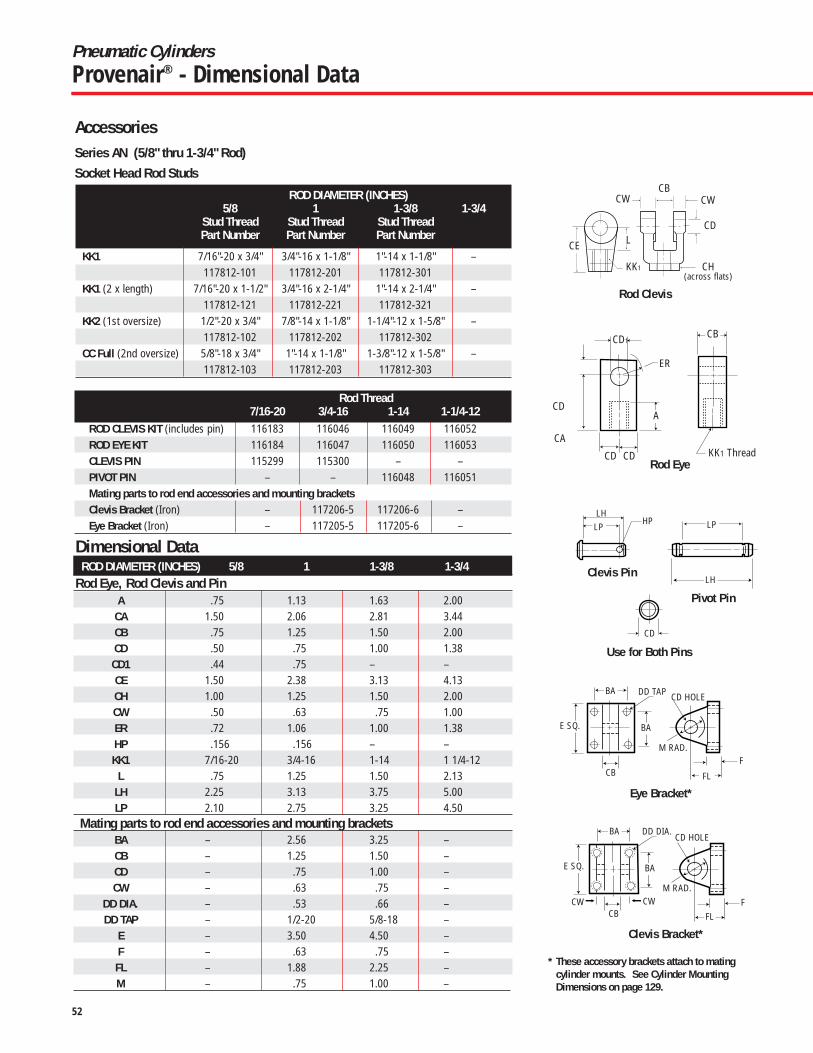
52
Pneumatic CylindersProvenair® - Dimensional Data
AccessoriesSeries AN (5/8" thru 1-3/4" Rod)Socket Head Rod Studs
Pivot Pin
Use for Both Pins
Clevis Pin
Eye Bracket*
Clevis Bracket*
LP LP
LH
BA
CW CW
F
FL
M RAD.
CD HOLE
CB
BA
DD TAP
E SQ.
BA
FFL
M RAD.
CD HOLE
CB
BA
DD DIA.
E SQ.
CD
HPLH
* These accessory brackets attach to matingcylinder mounts. See Cylinder Mounting Dimensions on page 129.
Rod Clevis
CA
CD
CE
KK1
CD
CWCWCB
CH(across flats)
L
KK1 Thread
CB
A
ER
CD1
CD CDRod Eye
ROD DIAMETER (INCHES)5/8 1 1-3/8 1-3/4
Stud Thread Stud Thread Stud ThreadPart Number Part Number Part Number
KK1 7/16"-20 x 3/4" 3/4"-16 x 1-1/8" 1"-14 x 1-1/8" –117812-101 117812-201 117812-301
KK1 (2 x length) 7/16"-20 x 1-1/2" 3/4"-16 x 2-1/4" 1"-14 x 2-1/4" –117812-121 117812-221 117812-321
KK2 (1st oversize) 1/2"-20 x 3/4" 7/8"-14 x 1-1/8" 1-1/4"-12 x 1-5/8" –117812-102 117812-202 117812-302
CC Full (2nd oversize) 5/8"-18 x 3/4" 1"-14 x 1-1/8" 1-3/8"-12 x 1-5/8" –117812-103 117812-203 117812-303
Dimensional DataROD DIAMETER (INCHES) 5/8 1 1-3/8 1-3/4
Rod Eye, Rod Clevis and PinA .75 1.13 1.63 2.00
CA 1.50 2.06 2.81 3.44CB .75 1.25 1.50 2.00CD .50 .75 1.00 1.38CD1 .44 .75 – –CE 1.50 2.38 3.13 4.13CH 1.00 1.25 1.50 2.00CW .50 .63 .75 1.00ER .72 1.06 1.00 1.38HP .156 .156 – –KK1 7/16-20 3/4-16 1-14 1 1/4-12
L .75 1.25 1.50 2.13LH 2.25 3.13 3.75 5.00LP 2.10 2.75 3.25 4.50
Mating parts to rod end accessories and mounting brackets BA – 2.56 3.25 –CB – 1.25 1.50 –CD – .75 1.00 –CW – .63 .75 –
DD DIA. – .53 .66 –DD TAP – 1/2-20 5/8-18 –
E – 3.50 4.50 –F – .63 .75 –FL – 1.88 2.25 –M – .75 1.00 –
Rod Thread7/16-20 3/4-16 1-14 1-1/4-12
ROD CLEVIS KIT (includes pin) 116183 116046 116049 116052ROD EYE KIT 116184 116047 116050 116053CLEVIS PIN 115299 115300 – –PIVOT PIN – – 116048 116051Mating parts to rod end accessories and mounting bracketsClevis Bracket (Iron) – 117206-5 117206-6 –Eye Bracket (Iron) – 117205-5 117205-6 –

53
Pneumatic CylindersProvenair®
TANK STYLEA Air / Oil T Air Reservoir
OrderingTanks & Reservoirs (1-1/2" thru 4" Bore)Two Provenair tank styles provide unique capabilities for your applications.
Style A, air-over-oil tanks provide the smooth control hydraulic systems are known for,without the expense, using shop air.
Style T reservoirs provide a supply of air near the point of use, allowing your system touse a smaller compressor or smaller system supply lines.
Q 1- 1/2"S 2”T 2- 1/2"
W 3-1/4"4 4"
ACTUATORSAll actuators begin with ASERIES (N)All Provenair Cylindersare Series N
SEALS
SIGHT GLASS LOCATION
PORT LOCATION MS4 mounts: Port locations other than “A”, call factory.
MOUNT
0 = 0 in1 = 1/8 in2 = 1/4 in3 = 3/8 in4 = 1/2 in5 = 5/8 in6 = 3/4 in7 = 7/8 in
Include dashes ( – ). Dashes are significant.
ENTER X IN THIS POSITION
BORE SIZE
TYPET Tank
STROKEWhole Inches
Fractions
B Buna-N V Viton
(X must be used with Tank Style T)
A H1, C1 (Std.)B H1, C2
D H1, C4F H2, C1
G H2, C2J H2, C4
U H4, C4
A MS1 B MS4 L MS7 X No Mount
X = None A = 1 B = 2 C = 4
N X XT X X X X X X X XA
Note:Maximum stroke 99 7/8", forlonger strokes consult factory.Style TMinimum stroke 2".Style ANote: Sight glass (required)Minimum 5" stroke.
Air/Oil Tank
Air Reservoir
Sight glass available inStyle A only
250 P.S.I.
00 = 0 in01 = 1 in02 = 2 in03 = 3 in04 = 4 in05 = 5 in06 = 6 in◊ ◊to to99 = 99 in
Volume and Dimensional information see page 55

54
Pneumatic CylindersProvenair®
Position Sensors (Switches)Reed SwitchesSwitch is normally open, load can be attached toBROWN or BLUE lead. The BROWN lead is the higherpotential side of the switch. In a magnetic field, the tworeeds are brought into contact to “make" the circuit.Reed switches have black, ‘two wire’ leads.
Sinking Sourcing
Mag. Field
N.O.
+DC +DCBROWN
BROWN
BLACK
BLACK
LOADLOAD
BLUE BLUE
Note: Operating temperature is 14 - 140˚ F and the environmental rating isIEC IP 67 in all three switch types. Std. Red LED requires min 18 mA.
Switch Specifications
Hall Effect SwitchesIt is important to note that Hall Effect switches mustalways have current through them to work. In amagnetic field, the semiconductor generates a voltageacross the sense leads. Removing the magnetic fieldreturns the switch to its normally open state. Halleffect switches have ‘three wire’ leads. Black leadsare sinking (NPN). Grey leads are sourcing (PNP).Load is controller.
There are two types of Hall Effect switches. Each isconnected differently. Check your PLC for the inputmethod used. Sinking (NPN) will sink current toground. Sourcing (PNP) will provide current fromthe +VDC.
Switch Mounting BracketsBore Model Number1-1/2" 1195842", 2-1/2" 1195853-1/4" and 4" 119586
Model Number 119581-1 119581-2 119581-3 119582-1 119582-2 119582-3 119583-1 119583-2 119583-3Lead Length/Type 1m bare 3m bare Plug 1m bare 3m bare Plug 1m bare 3m bare PlugLead Color Black Grey BlackSwitch Type REED PNP(SOURCING) NPN (SINKING)Input Voltage 100 VDC, 125 VAC Max. 10 - 30 VDC 5 - 30 VDC
– – 5 - 100mA @ 5VOperating Current 300mA (150mA Inductive) 7 - 100mA @ 12V 10 - 200mA @ 12V
– 14 - 200mA @ 24V 20 - 200mA @ 24VDetecting Distance 2.5 mm 1.5 mm 1.5 mmDetecting Width – 3.0 mm 3.0 mmResponse Time 1 mSec. Min. – –LED Function 18mA Min. 1mA Min. 1mA Min.
Technical Information:1. Do not exceed specification, permanent damage to the sensor may
occur.
2. For reed switch type sensors, polarity must be observed for theproper functioning of LED. Connect the brown wire in series with loadpositive (+) and the blue wire to negative (-) or power source space.If the polarity is reversed, reed switch remains functional but LED willremain in “OFF” state.
3. For solid-state type sensors, polarity must also be observed. Connectbrown wire to the positive (+) and the blue to the negative (-) of DCpower source. The black wire must connect to the load ONLY. If theblack wire is accidentally connected to the power source, permanentdamage to the sensor may occur.
4. An external protection circuit may be required if the reed switch isused with inductive load, such as relay or solenoid. For DC inductiveload, attach an external diode parallel to the load and use R -C circuitparallel with AC inductive load.
5. Keep sensors away from stray magnetic field to prevent malfunctions.
6. When using reed switch with capacitive load or if the lead wire lengthexceeds 10-meter, and inductor must be installed in series with thesensor to prevent damage (Sticking effect).
Dimensional information see page 55

55
Pneumatic CylindersProvenair® - Dimensional Data
Cylinder Bore (Inches)1 1/2" 2 & 2 1/2" 3 1/4" & 4"
B1 .51 .60 .80B2 1.50 1.77 2.45B3 .26 .26 .33
Tank DimensionsBORE A J TN E EE NPTF
Q 1-1/2" 2.005 0.94 0.63 2 3/8-18S 2" 2.005 0.94 0.88 2.5 3/8-18T 2-1/2" 2.005 0.94 1.25 3 3/8-18W 3-1/4" 2.505 1.19 1.50 3.75 1/2-144 4" 2.505 1.19 2.06 4.5 1/2-14
4 2
1
Determine port and sightglass locations looking at
top of tank.
Useable Volume Finder
Typical Air Oil Circuit
EE (N
PTF)
E
E
EE TN
JJ
A +
STRO
KE
Fill Portavailable inStyle A only
Style T or ADerive required circuit volume (V) in Cu. In.Divide (V) by factor from chart above todetermine stroke (enter stroke value intomodel number).Find unit length by adding stroke todimension A from tank dimension table.
Bore Style A Style TQ 1-1/2" 1.33 1.77S 2" 2.36 3.14T 2-1/2" 3.68 4.91W 3-1/4" 6.22 8.294 4" 9.42 12.56
Dimensional Data
Useable Volume Finder Tank Dimensions

56
Pneumatic CylindersRepair Kits & Valve/Cylinder Manifold
OrderingRepair Kits (Single Rod End Rod Bushings Provenair Series)
Order two kits fordouble rod end
cylinders.
Cylinder Bore Size (Inches)1-1/2 2 2 2-1/2 2-1/2 3-1/4 3-1/4 4 4
Rod Diameter 5/8 5/8 1 5/8 1 1 1-3/8 1 1-3/8Series AN Bushing 119454 119455 119456 119455 119456 119457 119458 119457 119458Series SN Bronze Bushing 114171 114171 114172 114171 114172 114172 114173 114172 114173
Cylinder Bore Size (Inches)5 5 6 6 8 8 10 10
Rod Diameter – 1 1-3/8 1-3/8 1-3/4 1-3/8 1-3/4 1-3/4 2Series AN Bushing – 115074 115075 115075 115076 115075 115076 115076 114130Series SN Bronze Bushing – 114172 114173 114172 114173 114173 114174 114174 114175
7150 7151 7152BORE SIZE 1/2 3/4 1-1/8
Seal Kits (Economair Series)
Reciprocating Assembly (Economair Series)
Micro-Air Series 01 (Seal Kits)
To order a repair kit, 1) Obtain model number from label on cylinder.2) Write “RK” for Repair Kit and 3) Using number from cylinder label,construct proper kit number as directed below.
Cylinder Model Number
EXAMPLE: 28 20 - 5 3 09-040
Order Kit No.:
RK 24 20 - 1 3For AllModelsWritein RK
SERIES NUMBERIf 23, (Noncushion), write 23If 24 (Cushion), 27 (Cushion, Pin Actuated), or 28 (Cushion, Magnetic) write 24
BORE SIZETake bore size from model number:18, 15, 20, 25, 30 or 40.
CYLINDER TYPEIf 1, 3, 4, 5, 6, or 7, write 1.
If 2, write 2.
PACKINGTake packing identifier from modelnumber: 0, 2, 3, 4, 5, 6, or 8
Only these numbers are used.
Cylinder Model Number
EXAMPLE: 28 20 - 2 3 8 9-040
Order Assembly No.:
RA 24 20 - 2 0 8 - X X X
To order a reciprocating assembly, 1) Obtain model numberfrom label on cylinder. 2) Write “RA” for reciprocatingassembly and 3) Using number from cylinder label,construct proper assembly number as directed below.
For AllModelsWritein RA SERIES NUMBER
If 23, (Noncushion), write 23If 24 (Cushion), 27 (Cushion, Pin Actuated), write 24If 28 (Magnetic), write 24
BORE SIZETake bore size frommodel number: 18, 15, 20, 25, 30 or 40.
PACKINGTake packing identifier from modelnumber: if 0 or 3 write 0
if 2, write 2if 4, 5 or 6 write 4
ROD MATERIALPACKING0 Standard Chrome8 Stainless Steel
STROKE
Only these numbers are used.
EXAMPLE RECIPROCATING ASSEMBLY MODEL NUMBER:R A 2 4 2 0 - 2 0 8 - 0 4 0
Supplies a stainless steel rod with 2” O-ring piston fora double rod end, 4” stroke.
CYLINDER TYPEIf 1, 3, 4, 5, 6, or 7, write 1.
If 2, write 2.

57
Pneumatic CylindersRepair Kits
X
X X XR K N X
Repair Kit DesignatorsS or R and K for Repair Kit, N for Provenair.
TypeDouble-Acting Single Rod = ADouble Acting Double Rod = BBore Size1 1/2 Q 2" S 2 1/2"T 3 1/4"W 4" 4 5" 5 6" 6 8" 8 10" YRod Diameter5/8" K 1" M 1-3/8" P 1 3/4" Q 2" S
Rod Style Not UsedReplacement SealsBuna-N B Buna-N + Mag. Pist. G (Use B)Viton V Viton + Mag. Pist. H (Use V)Self-Lube S Self-Lube Slippery + Mag. Pist. J (Use S)Replacement Cushion Seals (All Seal Kits Use “B")No Cushion Seals XCushions Both Ends BCushion Cap CCushion Head H
Port Location Not Used, Mounts Not Used, Stroke Not Used
BTo order a repair kit, use the model number from the cylinderlabel. Provenair repair kits start with the letters “RKN", “SKN" andappear in the first three positions. Using the numbers from thecylinder label, construct the remainder of the Repair Kit ornumber as directed below.
EXAMPLE REPAIR KIT MODEL: R K N A W M - V B
Supplies all Viton seals for a single rod end, 3 1/4" bore,1" diameter piston rod cylinder. Kit includes Teflonwearband and Viton cushion seals for both ends.
N X X X X X X X X X XA
Repair Kit Model Number S K
S
Not Used Not Used
Cylinder Model Number
To order a reciprocatingassembly, use the modelnumber from the cylinderlabel. Provenair reciprocatingassemblies start with theletters “RAN" or “RSN” andappear in the first threepositions. Using the numbersfrom the cylinder label,construct the remainder ofthe reciprocating assemblynumber as directed at left.
X X XR A N X X
N X X X X X X X X X X XACylinder Model Number
Reciprocating Assembly No.
Not Used Not Used
X X X
Port Location Not Used, Mounts Not Used
Stroke
R S
S
Reciprocating Assembly designatorsTypeDouble-Acting Single Rod = ADouble Acting Double Rod = BBore Size1 1/2 Q 2” S2 1/2" T 3 1/4" W 4" 4 5" 5 6" 6 8" 8 10" YRod Diameter5/8" K 1" M 1-3/8" P 1-3/4" Q 2" SRod Style A Chrome, Std Male (KK1) G S.S., Standard Male (KK1)B Chrome, Intermed. Male (KK2)H S.S., Intermediate Male (KK2)C Chrome, Full Male (CC) J S.S., Full Male (CC)D Chrome, Female (KK1) K S.S., Female (KK1)F Chrome, No Threads L S.S., No ThreadsSeals Not UsedReplacement Cushioned or Non CushionedNo Cushion Seals XCushions Both Ends B EXAMPLE RECIPROCATING ASSEMBLY MODEL:
R A N A S K - A B - 1 2 0 Supplies 5/8" diameter chrome rod, KK1 threads, cushioned, 12" stroke and
2" diameter piston for single rod end cylinder.
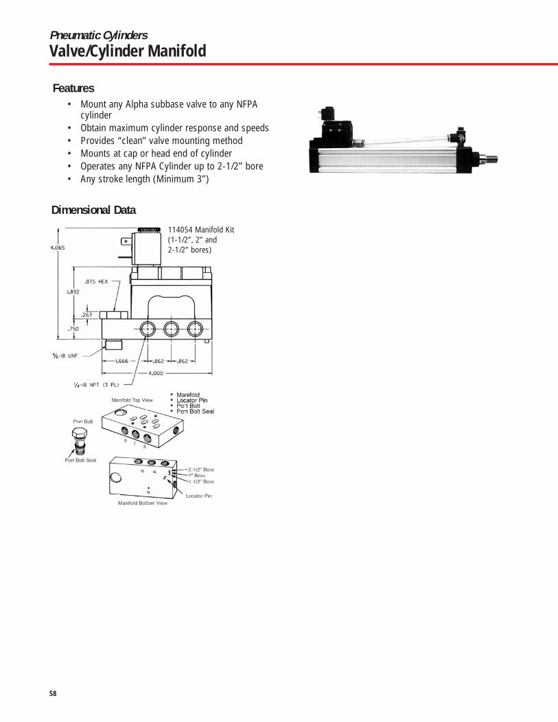
58
Pneumatic CylindersValve/Cylinder Manifold
114054 Manifold Kit(1-1/2”, 2” and2-1/2” bores)
Features
Dimensional Data
• Mount any Alpha subbase valve to any NFPAcylinder
• Obtain maximum cylinder response and speeds• Provides “clean” valve mounting method• Mounts at cap or head end of cylinder• Operates any NFPA Cylinder up to 2-1/2” bore• Any stroke length (Minimum 3”)

59
Big Value in a Compact Package– Stainless steel tie bolts and aluminum spacers lock precision machined heads tightly around a heavy walled, aluminum alloy cylinder barrel. The barrel's extremely smooth, self-lubricating interior surface insures highly reliable performance and extended seal life.
Superior Interchangeable Industrial Air Cylinders
Aluminum Alloy Barrel• Extremely smooth interior• Lighter weight
Aluminum alloy spacers (clear anodized) enclose stainless steel tie bolts
Superior Piston Rod Bushing:• Captive in cylinder head• Self lubricating• Higher load bearing capacity • Lower coefficient of friction
Hard chrome plated stain-less steel piston rod
Aluminum alloy heads (clear anodized)
Captive Rod Seal in precision machined groove
• Internally lubricated (Buna-N O’Ring)
Internally lubricated Carboxylated Nitrile O'Ring or optional U-Cup sealsHigh strength threaded
fastener and adhesive mates piston to rod
Buna-N O'Ring tube seals
Magnalube®G lubrication
Thick cover prevents impact damage
Compact CylindersPremair Series
Premair™ Series Round Compact, Interchangeable Cylinders

60
Available in 4 styles• Double acting, single end rod (Model SCC)
• Double acting, double end rod (Model SCD)
• Single acting, spring retract rod (Model SCS)
• Reverse acting, spring extend rod (Model SCR)
8 Bore sizes 1/2" thru 4"Strokes to 4" standard
Bore (in.)1/2 (05)3/4 (07)
1-1/8 (11)1-1/2 (15)
2 (20)2-1/2 (25)
3 (30)4 (40)
MaximumForce
5.2510.0011.5013.0013.0025.0025.0025.00
0.12 to 1" Stroke4.25
6.006.005.505.506.506.506.50
2.001 to 3" Stroke1.24
1.761.761.601.601.931.931.93
1.001 to 2" Stroke1.75
2.502.502.252.252.752.752.75
3.001 to 4" Stroke0.88
1.251.251.131.131.381.381.38
Spring Rate (lbs/inch) for Stroke Range
Spring Forces
Bore Diameter (in.) 1/2 3/4 1-1/8 1-1/2 2 2 1/2 3 4Rod Diameter (in.) 0.25 0.31 0.50 0.63 0.75 0.75 0.88 1.00Rod Area 0.05 0.08 0.19 0.31 0.44 0.44 0.60 0.79Push Area (Single Rod) 0.20 0.44 0.88 1.76 3.14 4.91 7.07 12.57Push Area (Double Rod) 0.15 0.36 0.69 1.45 2.66 4.47 6.47 11.78Pull Area 0.15 0.36 0.69 1.45 2.66 4.47 6.47 11.78
Cylinder Sizing Guide
• Body ....................................Aluminum Alloy• Heads..........Clear anodized aluminum alloy• Tie Bolts ............................... Stainless steel• Rod............... Chrome plated stainless steel• Piston .................................. Aluminum alloy• Rod end.....Female thread with wrench flats• Ports ...........................................Position #1• Seals .................. Internally lubricated Nitrile• Lubrication............................ Magnalube®-G• Rod bushing ......................High density iron
• Stroke tolerance . . . . . . . . . . . . . . . . . .± 1/64"• Media . . . . . . . . . . . . . . . . . . . . . . . . . . . . . Air • Pressure rating, maximum . . . . . . . . . 250 psi• Minimum recommended operating pressure . . . . . . . . . . . . . 15 psi• Temperature rating
Cylinder . . . . . . . . . . . . . . –25° to +225°F(–32° to +121°C)
• Temperature ratingElectronic sensors . . . . . . . –5° to +175°F
(–20° to +80°C)
Ratings
Compact CylindersPremair Series
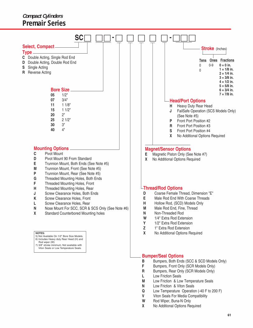
61
TypeC Double Acting, Single Rod EndD Double Acting, Double Rod EndS Single ActingR Reverse Acting
SC - -
Bore Size05 1/2"07 3/4"11 1 1/8"15 1 1/2"20 2"25 2 1/2"30 3"40 4"
Mounting OptionsC Pivot MountD Pivot Mount 90 From StandardE Trunnion Mount, Both Ends (See Note #5)M Trunnion Mount, Front (See Note #5)P Trunnion Mount, Rear (See Note #5)G Threaded Mounting Holes, Both EndsF Threaded Mounting Holes, FrontH Threaded Mounting Holes, RearJ Screw Clearance Holes, Both EndsK Screw Clearance Holes, FrontL Screw Clearance Holes, RearN Nose Mount For SCC, SCR & SCS Only (See Note #6)X Standard Counterbored Mounting holes
Bumper/Seal OptionsB Bumpers, Both Ends (SCC & SCD Models Only)F Bumpers, Front Only (SCR Models Only)R Bumpers, Rear Only (SCR Models Only)L Low Friction SealsM Low Friction & Low Temperature SealsN Low Friction & Viton SealsQ Low Temperature Operation (-40 F to 200 F)V Viton Seals For Media CompatibilityW Rod Wiper, Buna-N OnlyX No Additional Options Required
Thread/Rod OptionsD Coarse Female Thread, Dimension "E"E Male Rod End With Coarse ThreadsH Hollow Rod, (SCD) Models OnlyM Male Rod End, Fine, ThreadN Non-Threaded RodW 1/4" Extra Rod ExtensionY 1/2" Extra Rod ExtensionZ 1" Extra Rod ExtensionX No Additional Options Required
Magnet/Sensor OptionsE Magnetic Piston Only (See Note #7)X No Additional Options Required
Head/Port OptionsH Heavy Duty Rear HeadJ FailSafe Operation (SCS Models Only)
(See Note #5)P Front Port Position #2R Front Port Position #3S Front Port Position #4X No Additional Options Required
Stroke (Inches)
Tens00
Ones0-9
Fractions0 = 0 in.1 = 1/8 in.2 = 1/4 in.3 = 3/8 in.4 = 1/2 in.5 = 5/8 in.6 = 3/4 in.7 = 7/8 in.
NOTES:5) Not Available On 1/2" Bore Size Models.6) Includes Heavy duty Rear Head (H) and
Rod wiper (W)7) 3/8" stroke minimum. Not available with
Viton Seals or Low Temperature Seals.
Select, Compact
Compact CylindersPremair Series

MTSqua
LD
Q PinDia.
TH S
SDSquare
TL
SH BoltHole Dia.
M
HT
LT
BA
NBN Hole Dia.
NA
BTBolt Siz
NT
S
S
MSLN Q Hole Dia
E Thread
Clevis BracketAnodized aluminum alloy Chrome plated steel pin included
Trunnion Bracket (pair)Anodized aluminum alloy complete with bronze pivot bushings
Rod PivotSteel with bronze pivot bushing and nut
Bore3/4 (07)
1-1/8 (11)1-1/2 (15)
2 (20)2-1/2 (25)
3 (30)4 (40)
BA0.56
0.81
0.94
1.06
Dimensions (inches)
BT#10
1/4
5/16
3/8
HT0.63
0.88
1.00
1.25
LT1.12
1.50
1.63
1.88
M0.31
0.50
0.63
0.75
N0.126
0.251
0.313
0.376
NA0.30
0.38
0.45
0.55
NB0.22
0.31
0.38
0.44
Kit No.SCABT-1
SCABT-2
SCABT-3
SCABT-4
Bore1/2 (05)3/4 (07)
1-1/8 (11)1-1/2 (15)
2 (20)2-1/2 (25)
3 (30)4 (40)
LN0.380.380.630.63
0.75
0.880.88
Dimensions (inches)
MS0.470.470.470.72
0.72
1.001.00
NT0.250.250.250.44
0.44
0.630.63
Q0.1870.1870.1870.375
0.375
0.6250.625
S0.380.380.380.75
0.75
1.001.00
Kit No.SCARP-0SCARP-1SCARP-2SCARP-3SCARP-4
SCARP-5SCARP-6
E#8-32 UNC#10-32 UNF5/16-24 UNF3/8-24 UNF
1/2-20 UNF
5/8-18 UNF3/4-16 UNF
Bore1/2 (05)3/4 (07)
1-1/8 (11)1-1/2 (15)
2 (20)2-1/2 (25)
3 (30)4 (40)
LD
0.56
0.94
1.25
Dimensions (inches)
MT
0.75
1.38
2.00
Q
0.187
0.375
0.625
S
0.39
0.75
1.00
SH
#6
#10
0.25
SD
1.00
1.75
2.50
TH
0.16
0.22
0.25
TL
0.78
1.34
1.81
Kit No.
SCABC-1
SCABC-2
SCABC-3The bracket is intended for mounting with either a rod pivot or pivot mount; it is not intended to mount directly with the rear cylinder head.
AccessoriesStandard Series
Selection Guide
AccessoryClevis Bracket
Trunnion BracketRod Pivot
Compact CylindersPremair Series

63
32(1.26)
34(1.34)
8.5(.33)
9.8(.39)
Sensor
Pigtail
1, 2 or 5
Meter Cable
Sensor Specifications & Ordering Information
Quick Disconnect Part No.*
SCAMS-3
SCAMS-4
Prewired 9 ft.Part No.
SCAMS-1
SCAMS-2
Sensor Type
Electronic
Electronic
Wire Leads
3
3
Ordering Guide – Dovetail Style Magnetic Sensor with LED
Electrical Characteristics
Sourcing PNP 6-24 VDC, 0.20 Amp Max current, 0.5 Voltage Drop
Sinking NPN 6-24 VDC, 0.20 Amp Max current, 0.5 Voltage Drop
Note*: Quick disconnect styles are supplied with 6 inch pigtail with male connector. Order female cordsets separately.
• Encased in a plastic housing, dovetail style electronic sensors are corrosion resistant.45° wire outlet allows close mounting.
• Two methods of mounting are available:1. Tie bolt spacer mounted clamps2. Adhesive mounted dovetail extrusions
• Order sensors separately from the table below
Sensor Temperature Range-20° to +80° C (-4° to +176° F)
Length1 Meter2 Meters5 Meters
Part No.SCAFC-1SCAFC-2SCAFC-5
Female Cordsetsfor
Quick Disconnect
Tie Bolt Spacer
Position sensors with spacer mounted clamps
Clamp Part No. SCAMC-1 SCAMC-2 SCAMC-3 SCAMC-4 SCAMC-5 SCAMC-6To Fit Bore 1/2" 3/4" 1-1/8" 1-1/2" & 2" 2-1/2" & 3" 4"
Clamp Selection Guide
Order clamps and sensors separately
Compact CylindersMagnetic Position Sensing

64
Model SCCDouble Acting, Single Rod
1 3
Ba* + Stroke 0.13Location of Mtg. Holes
for 1/2" Bore only
J TYP. K TYP.
F Rod Dia.
C Bolt Circle
L Port
2
4
A
DD Clearance for D SHCS
H
E
*Note: Some options effect cylinder length
1 3
Bb* + Stroke 0.130.13+ StrokeLocation of Mtg. Holes
for 1/2" Bore only
J TYP. K TYP.
F Rod Dia.
C Bolt Circle
L Port
2
4
A
DD Clearancefor D SHCS
H
E
Model SCDDouble Acting, Double Rod
*Note: Some options effect cylinder length
Standard Strokes – All Models: • 1/8 • 1/4 • 3/8 • 1/2 • 5/8 • 3/4 • 7/8 • 1 • 1-1/4 • 1-1/2 • 1-3/4 • 2 • 2-1/2 • 3 • 3-1/2 • 4
Bc* for Stroke Range
Bore1/2 (05)3/4 (07)
1-1/8 (11)1-1/2 (15)
2 (20)2-1/2 (25)
3 (30)4 (40)
A1.121.502.002.623.123.754.255.50
Ba*0.560.560.880.880.941.191.251.56
Bb*0.690.690.941.001.061.311.381.69
0-10.810.810.880.880.941.191.251.56
1.001-21.381.381.501.501.562.062.122.44
2.001-31.961.942.132.132.192.943.003.31
3.001-42.522.502.752.752.813.813.884.19
0-11.061.061.381.381.441.942.002.31
1.001-21.621.622.002.002.062.812.883.19
2.001-32.142.192.632.632.692.812.883.19
3.001-43.212.753.253.25NANANANA
Bd* for Stroke Range
DD24444444
C0.881.221.692.192.693.253.784.94
Dimensions (inches)
Compact CylindersPremair Series

Model SCSSingle Acting, Spring Retract
1 3
Bc * + Stroke 0.13Location of Mtg. Holes
for 1/2" Bore only
J TYP. K TYP.
F Rod Dia.
C Bolt Circle
L Port
2
4
A
DD Clearance for D SHCS
H
E
*Note: Some options effect cylinder length
1 3
Bd * + Stroke 0.13 + Stroke
Location of Mtg. Holesfor 1/2" Bore only
J TYP. K TYP.
F Rod Dia.
C Bolt Circle
L Port
2
4
A
DD Clearance for D SHCS
H
E
Model SCRReverse Acting, Spring Extend
Standard Strokes – All Models: • 1/8 • 1/4 • 3/8 • 1/2 • 5/8 • 3/4 • 7/8 • 1 • 1-1/4 • 1-1/2 • 1-3/4 • 2
*Note: Some options effect cylinder length
SCC, SCS
Bore1/2 (05)3/4 (07)
1-1/8 (11)1-1/2 (15)
2 (20)2-1/2 (25)
3 (30)4 (40)
Base1.21.94.99.6
13.022.428.955.7
Adder per1/8 of Stroke
0.080.10.30.40.50.60.81.0
SCD SCRApproximate Cylinder Weights (ounces) SCC, SCS, SCD, SCR
Base1.32.15.8
11.215.228.038.071.8
Adder per1/8 of Stroke
0.150.20.40.60.70.81.11.3
Base1.32.05.3
10.514.025.032.561.8
Adder per1/8 of Stroke
0.080.10.30.40.50.60.81.0
Adder per1/8 of Strokefor -H Option
0.10.150.30.50.60.70.91.1
Adder to BaseWeight
0.10.21.11.82.73.13.55.9
Nose Mount Option
Bore1/2 (05)3/4 (07)
1-1/8 (11)1-1/2 (15)
2 (20)2-1/2 (25)
3 (30)4 (40)
D#4#6#6#10#101/41/45/16
E Standard#8-32 UNC#10-32 UNF5/16-24 UNF3/8-24 UNF1/2-20 UNF1/2-20 UNF5/8-18 UNF3/4-16 UNF
1/8 – 1/2 5/8 +0.30-0.46 0.460.30-0.46 0.460.37-0.63 0.700.37-0.70 0.700.30-0.63 0.700.42-0.70 0.700.45-0.73 0.730.40-0.70 0.80
F0.250.310.500.630.750.750.881.00
H0.220.250.440.500.630.630.750.88
J0.340.340.500.500.530.660.690.84
K0.140.140.250.250.250.330.330.42
L#10-32 UNF#10-32 UNF
1/8 NPT1/8 NPT1/8 NPT1/4 NPT1/4 NPT3/8 NPT
Dimensions (inches)E Depth for Stroke Range
Compact CylindersPremair Series

Compact Cylinders
Premair Series

Hollow Rod OptionDeviations from Standard Dimensions
90 Typ.
3/4" Bore 43All others 45
R Hole (4)Threaded
C Bolt Circle
90° Typ.
R Hole (2)Threaded
C Bolt Circle AC AD Thread
0.13
AF
AE
AB AA
Nose Mount Available on SCC, SCS, SCR.Included heavy duty rear head. See length adder above.
Threaded Mounting Holes1/2" BoreAvailable either or both ends.
3/4" Bore & Up
‡ Heavy duty rear head is recommended for applications where the cylinder is mounted on the front face or trunnion-mounted, and impact loading (20 or more cycles/minute) occurs between the piston and rear head. It increases the overall length of the cylinder as shown.† A minimum stroke of 3/8” is required to sense end-of-stroke positions. For low friction seals used in conjunction with magnetic position sensing, use “E” or “M” sensor options only.
Magnetic Position Sensing† (E or M)
Bore1/2 (05)3/4 (07)
1-1/8 (11)1-1/2 (15)
2 (20)2-1/2 (25)
3 (30)4 (40)
SCC, SCD0.880.880.880.880.880.880.880.88
Length Adder (inches)
Low FrictionSeals
0.250.250.380.380.380.380.500.50
Heavy DutyRear Head‡
0.130.130.190.190.190.250.250.38
SCS0.630.880.880.880.880.880.880.88
SCR0.380.880.880.880.880.880.880.88
Bore1/2 (05)3/4 (07)
1-1/8 (11)1-1/2 (15)
2 (20)2-1/2 (25)
3 (30)4 (40)
Dimensions (inches)
AA.06.06.13.13.19.25.25.19
AC.38.38.75.75.88
1.001.001.12
AE.50.62
1.001.251.381.381.381.75
AB0.75 Hex0.75 Hex1.50 Hex1.88 Hex1.88 Hex1.88 Hex1.88 Hex2.62 Hex
AD1/2 – 20 UNF-2A5/8 – 18 UNF-2A 1– 14 UNF-2A
1-1/4 – 12 UNF-2A1-3/8 – 12 UNF-2A1-3/8 – 12 UNF-2A1-3/8 – 12 UNF-2A1-3/4 – 12 UN-2A
AF.31.25.55.52.52.52.52.88
C0.881.221.692.192.693.253.784.94
R#4 – 40 UNC#6 – 32 UNC# 6 – 32 UNC# 10 – 24 UNC# 10 – 24 UNC1/4 – 20 UNC1/4 – 20 UNC5/16 – 18 UNC
Bore1/2 (05)3/4 (07)
1-1/8 (11)1-1/2 (15)
2 (20)2-1/2 (25)
3 (30)4 (40)
Female RodThread
0.140.140.220.280.380.380.440.50
Male RodThread
N/A0.09
0.160.190.250.250.310.38
Hole Diameter
Bore1/2 (05)3/4 (07)
1-1/8 (11)1-1/2 (15)
2 (20)2-1/2 (25)
3 (30)4 (40)
Foot-Pounds1228100120130130130150
Maximum Torque for
Nose Mount Option
Compact CylindersPremair Series

10 Bore Sizes12mm thru 100mm
• NPT Ports• Stainless Steel Rod
• Space Saving Design
Low-profile, aluminum cylinders are designed for compact, space-saving applications. All models have magnetic pistons and areswitch-ready for accurate position sensing. Low-profile, solid stateswitches slide into machined grooves located on the cylinder body.Viton seals for higher temperature rating than nitrile.Stainless steelpiston rods are hard chrome plated for superior wear and corrosionresistance. Piston is attached to rod with a flat head screw to min-imize pounding and vibration. Mounting through holes are thread-ed for easy mounting hardware installation.
Ratings
• Fluid . . . . . . . . . . . . . . . . . . . . . . . . .AIR• Max. Operating Pressure . . . . . . . .140 PSI• Min. Operating Pressure . . . . . . . . .7 PSI• Ambient and Fluid Temperature . . .15-140 F (-10 - 60 C)• Lubrication . . . . . . . . . . . . . . . . . . . .Not Required• Cushion . . . . . . . . . . . . . . . . . . . . . .None
• Rod End Thread . . . . . . . .Female (standard)• Stroke Tolerence . . . . . . . .0.039 in (+10/-0mm)• Mounting . . . . . . . . . . . . . .Through Hole (Standard)• Piston Speed . . . . . . . . . . .2-20inch/sec (50-500mm/sec)
Cylinder Force
Basic Cylinder Weights
• Buna Seals Standard• Light Weight Aluminum Body
Bore Size Operating Pressure PSI50 75 100
012(1/2 nom) 8.7 13.1 17.56.6 9.8 13.1
016(5/8 nom) 15.6 23.4 31.211.7 17.5 23.4
020(3/4 nom) 24.3 36.5 48.618.2 27.3 36.5
025(1 nom) 38 57 7629.3 43.9 58.5
032(11/4 nom) 62.3 93.5 12.546.8 70.1 93.5
Bore Size Operating Pressure PSI50 75 100
040(11/2 nom.) 97.4 146 19581.8 123 164
050(2 nom) 152 228 304128 192 256
063(21/2 nom) 242 362 483217 326 434
080(31/4 nom) 390 584 779352 527 703
100(4 nom) 609 913 1217554 831 1108
Cylinder force
Basic Cylinder Weights (lbs)
Bore Stroke (inch)
(in)
5
(.20)
10
(.39)
15
(.59)
20
(.79)
25
(.98)
30
(1.18)
35
(1.38)
40
(1.57)
45
(1.77)
50
(1.97)
75
(2.95)
100
(3.94)
1/2 0.110 0.126 0.141 0.157 0.172 0.187 - - - - - -
5/8 0.157 0.181 0.207 0.232 0.256 0.280 - - - - - -
3/4 0.229 0.271 0.315 0.359 0.406 0.450 0.494 0.540 0.584 0.631 - -
1 0.284 0.331 0.395 0.423 0.472 0.518 0.564 0.613 0.657 0.706 - -
1-1/4 0.571 0.598 0.624 0.650 0.701 0.750 0.800 0.851 0.902 0.961 1.22 1.47
1-1/2 0.752 0.805 0.858 0.908 0.953 0.997 1.05 1.09 1.14 1.2 1.44 1.68
2 - 1.10 1.17 1.25 1.34 1.43 1.5 1.58 1.66 1.78 2.18 2.5
2-1/2 - 1.60 1.69 1.78 1.87 1.97 2.06 2.15 2.23 2.38 2.84 3.29
3-1/4 - 3.53 3.74 0.4 4.16 4.36 4.57 4.78 4.99 5.28 6.31 7.33
4 - 5.55 5.68 5.81 6.05 6.29 6.52 6.75 6.97 7.31 8.45 9.59
• Female Rod Threads Standard
Compact CylindersPremair Series
Low-profile, aluminum cylinders are designed for compact,spacesaving applications. All models have magnetic pistons andare switch-ready for accurate position sensing. Low-profile, solidstate switches slide into machined grooves located on the cylinderbody. Stainless steel piston rods are hard chrome plated forsuperior wear and corrosion resistance. Piston is attached to rodwith a flat head screw to minimize pounding and vibration.Mounting through holes are threaded for easy mounting hardwareinstallation.

Available Models
M D S - A A A D N -
Bore(mm) . . . .Stroke (mm) . . . . . .Model number12 . . . . . . . . . . . . . . . . . . . .5 . . . . . . . . . . . . . .MDS12-AAADN-00512 . . . . . . . . . . . . . . . . . . . .10 . . . . . . . . . . . . .MDS12-AAADN-01012 . . . . . . . . . . . . . . . . . . . .15 . . . . . . . . . . . . .MDS12-AAADN-01512 . . . . . . . . . . . . . . . . . . . .20 . . . . . . . . . . . . .MDS12-AAADN-02012 . . . . . . . . . . . . . . . . . . . .25 . . . . . . . . . . . . .MDS12-AAADN-02512 . . . . . . . . . . . . . . . . . . . .30 . . . . . . . . . . . . .MDS12-AAADN-03016 . . . . . . . . . . . . . . . . . . . .5 . . . . . . . . . . . . . .MDS16-AAADN-00516 . . . . . . . . . . . . . . . . . . . .10 . . . . . . . . . . . . .MDS16-AAADN-01016 . . . . . . . . . . . . . . . . . . . .15 . . . . . . . . . . . . .MDS16-AAADN-01516 . . . . . . . . . . . . . . . . . . . .20 . . . . . . . . . . . . .MDS16-AAADN-02016 . . . . . . . . . . . . . . . . . . . .25 . . . . . . . . . . . . .MDS16-AAADN-02516 . . . . . . . . . . . . . . . . . . . .30 . . . . . . . . . . . . .MDS16-AAADN-03020 . . . . . . . . . . . . . . . . . . . .5 . . . . . . . . . . . . . .MDS20-AAADN-00520 . . . . . . . . . . . . . . . . . . . .10 . . . . . . . . . . . . .MDS20-AAADN-01020 . . . . . . . . . . . . . . . . . . . .15 . . . . . . . . . . . . .MDS20-AAADN-01520 . . . . . . . . . . . . . . . . . . . .20 . . . . . . . . . . . . .MDS20-AAADN-02020 . . . . . . . . . . . . . . . . . . . .25 . . . . . . . . . . . . .MDS20-AAADN-02520 . . . . . . . . . . . . . . . . . . . .30 . . . . . . . . . . . . .MDS20-AAADN-03020 . . . . . . . . . . . . . . . . . . . .35 . . . . . . . . . . . . .MDS20-AAADN-03520 . . . . . . . . . . . . . . . . . . . .40 . . . . . . . . . . . . .MDS20-AAADN-04020 . . . . . . . . . . . . . . . . . . . .45 . . . . . . . . . . . . .MDS20-AAADN-04520 . . . . . . . . . . . . . . . . . . . .50 . . . . . . . . . . . . .MDS20-AAADN-05025 . . . . . . . . . . . . . . . . . . . .5 . . . . . . . . . . . . . .MDS25-AAADN-00525 . . . . . . . . . . . . . . . . . . . .10 . . . . . . . . . . . . .MDS25-AAADN-01025 . . . . . . . . . . . . . . . . . . . .15 . . . . . . . . . . . . .MDS25-AAADN-01525 . . . . . . . . . . . . . . . . . . . .20 . . . . . . . . . . . . .MDS25-AAADN-02025 . . . . . . . . . . . . . . . . . . . .25 . . . . . . . . . . . . .MDS25-AAADN-02525 . . . . . . . . . . . . . . . . . . . .30 . . . . . . . . . . . . .MDS25-AAADN-03025 . . . . . . . . . . . . . . . . . . . .35 . . . . . . . . . . . . .MDS25-AAADN-03525 . . . . . . . . . . . . . . . . . . . .40 . . . . . . . . . . . . .MDS25-AAADN-04025 . . . . . . . . . . . . . . . . . . . .45 . . . . . . . . . . . . .MDS25-AAADN-04525 . . . . . . . . . . . . . . . . . . . .50 . . . . . . . . . . . . .MDS25-AAADN-05032 . . . . . . . . . . . . . . . . . . . .5 . . . . . . . . . . . . . .MDS32-AAADN-00532 . . . . . . . . . . . . . . . . . . . .10 . . . . . . . . . . . . .MDS32-AAADN-01032 . . . . . . . . . . . . . . . . . . . .15 . . . . . . . . . . . . .MDS32-AAADN-01532 . . . . . . . . . . . . . . . . . . . .20 . . . . . . . . . . . . .MDS32-AAADN-02032 . . . . . . . . . . . . . . . . . . . .25 . . . . . . . . . . . . .MDS32-AAADN-02532 . . . . . . . . . . . . . . . . . . . .30 . . . . . . . . . . . . .MDS32-AAADN-03032 . . . . . . . . . . . . . . . . . . . .35 . . . . . . . . . . . . .MDS32-AAADN-03532 . . . . . . . . . . . . . . . . . . . .40 . . . . . . . . . . . . .MDS32-AAADN-04032 . . . . . . . . . . . . . . . . . . . .45 . . . . . . . . . . . . .MDS32-AAADN-04532 . . . . . . . . . . . . . . . . . . . .50 . . . . . . . . . . . . .MDS32-AAADN-05032 . . . . . . . . . . . . . . . . . . . .75 . . . . . . . . . . . . .MDS32-AAADN-07532 . . . . . . . . . . . . . . . . . . .100 . . . . . . . . . . . . .MDS32-AAADN-10040 . . . . . . . . . . . . . . . . . . . .5 . . . . . . . . . . . . . .MDS40-AAADN-00540 . . . . . . . . . . . . . . . . . . . .10 . . . . . . . . . . . . .MDS40-AAADN-01040 . . . . . . . . . . . . . . . . . . . .15 . . . . . . . . . . . . .MDS40-AAADN-01540 . . . . . . . . . . . . . . . . . . . .20 . . . . . . . . . . . . .MDS40-AAADN-02040 . . . . . . . . . . . . . . . . . . . .25 . . . . . . . . . . . . .MDS40-AAADN-02540 . . . . . . . . . . . . . . . . . . . .30 . . . . . . . . . . . . .MDS40-AAADN-030
Bore(mm) . . . .Stroke (mm) . . . . . .Model number40 . . . . . . . . . . . . . . . . . . . .35 . . . . . . . . . . . . .MDS40-AAADN-03540 . . . . . . . . . . . . . . . . . . . .40 . . . . . . . . . . . . .MDS40-AAADN-04040 . . . . . . . . . . . . . . . . . . . .45 . . . . . . . . . . . . .MDS40-AAADN-04540 . . . . . . . . . . . . . . . . . . . .50 . . . . . . . . . . . . .MDS40-AAADN-05040 . . . . . . . . . . . . . . . . . . . .75 . . . . . . . . . . . . .MDS40-AAADN-07540 . . . . . . . . . . . . . . . . . . .100 . . . . . . . . . . . . .MDS40-AAADN-10050 . . . . . . . . . . . . . . . . . . . .10 . . . . . . . . . . . . .MDS50-AAADN-01050 . . . . . . . . . . . . . . . . . . . .15 . . . . . . . . . . . . .MDS50-AAADN-01550 . . . . . . . . . . . . . . . . . . . .20 . . . . . . . . . . . . .MDS50-AAADN-02050 . . . . . . . . . . . . . . . . . . . .25 . . . . . . . . . . . . .MDS50-AAADN-02550 . . . . . . . . . . . . . . . . . . . .30 . . . . . . . . . . . . .MDS50-AAADN-03050 . . . . . . . . . . . . . . . . . . . .35 . . . . . . . . . . . . .MDS50-AAADN-03550 . . . . . . . . . . . . . . . . . . . .40 . . . . . . . . . . . . .MDS50-AAADN-04050 . . . . . . . . . . . . . . . . . . . .45 . . . . . . . . . . . . .MDS50-AAADN-04550 . . . . . . . . . . . . . . . . . . . .50 . . . . . . . . . . . . .MDS50-AAADN-05050 . . . . . . . . . . . . . . . . . . . .75 . . . . . . . . . . . . .MDS50-AAADN-07550 . . . . . . . . . . . . . . . . . . .100 . . . . . . . . . . . . .MDS50-AAADN-10063 . . . . . . . . . . . . . . . . . . . .10 . . . . . . . . . . . . .MDS63-AAADN-01063 . . . . . . . . . . . . . . . . . . . .15 . . . . . . . . . . . . .MDS63-AAADN-01563 . . . . . . . . . . . . . . . . . . . .20 . . . . . . . . . . . . .MDS63-AAADN-02063 . . . . . . . . . . . . . . . . . . . .25 . . . . . . . . . . . . .MDS63-AAADN-02563 . . . . . . . . . . . . . . . . . . . .30 . . . . . . . . . . . . .MDS63-AAADN-03063 . . . . . . . . . . . . . . . . . . . .35 . . . . . . . . . . . . .MDS63-AAADN-03563 . . . . . . . . . . . . . . . . . . . .40 . . . . . . . . . . . . .MDS63-AAADN-04063 . . . . . . . . . . . . . . . . . . . .45 . . . . . . . . . . . . .MDS63-AAADN-04563 . . . . . . . . . . . . . . . . . . . .50 . . . . . . . . . . . . .MDS63-AAADN-05063 . . . . . . . . . . . . . . . . . . . .75 . . . . . . . . . . . . .MDS63-AAADN-07563 . . . . . . . . . . . . . . . . . . .100 . . . . . . . . . . . . .MDS63-AAADN-10080 . . . . . . . . . . . . . . . . . . . .10 . . . . . . . . . . . . .MDS80-AAADN-01080 . . . . . . . . . . . . . . . . . . . .15 . . . . . . . . . . . . .MDS80-AAADN-01580 . . . . . . . . . . . . . . . . . . . .20 . . . . . . . . . . . . .MDS80-AAADN-02080 . . . . . . . . . . . . . . . . . . . .25 . . . . . . . . . . . . .MDS80-AAADN-02580 . . . . . . . . . . . . . . . . . . . .30 . . . . . . . . . . . . .MDS80-AAADN-03080 . . . . . . . . . . . . . . . . . . . .35 . . . . . . . . . . . . .MDS80-AAADN-03580 . . . . . . . . . . . . . . . . . . . .40 . . . . . . . . . . . . .MDS80-AAADN-04080 . . . . . . . . . . . . . . . . . . . .45 . . . . . . . . . . . . .MDS80-AAADN-04580 . . . . . . . . . . . . . . . . . . . .50 . . . . . . . . . . . . .MDS80-AAADN-05080 . . . . . . . . . . . . . . . . . . . .75 . . . . . . . . . . . . .MDS80-AAADN-07580 . . . . . . . . . . . . . . . . . . .100 . . . . . . . . . . . . .MDS80-AAADN-10010 . . . . . . . . . . . . . . . . . . . .10 . . . . . . . . . . . . .MDS10-AAADN-01010 . . . . . . . . . . . . . . . . . . . .15 . . . . . . . . . . . . .MDS10-AAADN-01510 . . . . . . . . . . . . . . . . . . . .20 . . . . . . . . . . . . .MDS10-AAADN-02010 . . . . . . . . . . . . . . . . . . . .25 . . . . . . . . . . . . .MDS10-AAADN-02510 . . . . . . . . . . . . . . . . . . . .30 . . . . . . . . . . . . .MDS10-AAADN-03010 . . . . . . . . . . . . . . . . . . . .35 . . . . . . . . . . . . .MDS10-AAADN-03510 . . . . . . . . . . . . . . . . . . . .40 . . . . . . . . . . . . .MDS10-AAADN-04010 . . . . . . . . . . . . . . . . . . . .45 . . . . . . . . . . . . .MDS10-AAADN-04510 . . . . . . . . . . . . . . . . . . . .50 . . . . . . . . . . . . .MDS10-AAADN-05010 . . . . . . . . . . . . . . . . . . . .75 . . . . . . . . . . . . .MDS10-AAADN-07510 . . . . . . . . . . . . . . . . . . .100 . . . . . . . . . . . . .MDS10-AAADN-100
Compact CylindersPremair Series

70
Dimensions mm (inch)BORE mm
(Nom. In.) A B E H K L M MM OO P W
(Inch) (NPT)
12 (1/2) 31.5 (1.24) 28.0 (1.10) 25 (0.98) 8-32 5 (0.20) 3.5 (0.14) 22 (0.87) 6 (0.236) 6.5 (0.26) 10-32 23 (0.90)
16 (5/8) 34.0 (1.34) 30.5 (1.20) 29 (1.14) 8-32 6 (0.24) 3.5 (0.14) 28 (1.10) 8 (0.315) 6.5 (0.26) 10-32 27.2 (1.07)
20 (3/4) 36.0 (1.42) 31.5 (1.24) 36 (1.42) 10-32 8 (.031) 4.5 (0.18) 36 (1.42) 10 (0.394) 9 (0.35) 10-32 31.2 (1.23)
25 (1) 37.5 (1.48) 32.5 (1.28) 40 (1.57) 1/4-28 10 (0.39) 5 (0.20) 40 (1.57) 12 (0.472) 9 (0.35) 10-32 36.9 (1.45)
32 (1-1/4) 40.0 (1.57) 33.0 (1.30) 44.5 (1.75) 5/16-24 14 (0.55) 7 (0.28) 34 (1.34) 16 (0.630) 9 (0.35) 1/8 49.3 (1.94)
40 (1-1/2) 46.5 (1.83) 39.5 (1.56) 52 (2.05) 3/8-24 14 (0.55) 7 (0.28) 40 (1.57) 16 (0.630) 9 (0.35) 1/8 57 (2.24)
50 (2) 48.5 (1.91) 40.5 (1.59) 63.7 (2.51) 1/2-20 17 (0.67) 8 (0.31) 50 (1.97) 20 (0.787) 11 (0.43) 1/4 70.6 (2.78)
63 (2-1/2) 54.0 (2.13) 46.0 (1.81) 76.7 (3.02) 1/2-20 17 (0.67) 8 (0.31) 60 (2.36) 20 (0.787) 14 (0.55) 1/4 83.6 (3.29)
80 (3-1/4) 63.5 (2.50) 53.5 (2.11) 97.8 (3.85) 5/8-18 22 (0.87) 10 (0.39) 77 (3.03) 25 (0.984) 17.5 (0.69) 3/8 104 (4.09)
100 (4) 75.0 (2.95) 63.0 (2.48) 115.3 (4.54) 3/4-16 27 (1.06) 12 (0.47) 94 (3.70) 30 (1.181) 17.5 (0.69) 3/8 121.9 (4.80)
32-100mm
12-25mm
Compact CylindersPremair Series

Rod clevis Bore Inch Metric
mm (in) Part Number Part Number12 (1/2) 114818-12 114819-1216 (5/8) 114818-16 114819-1620 (3/4) 114818-20 114819-2025 (1) 114818-25 114819-2532 (1-1/4) 114818-32 114819-3240 (1-1/2) 114818-40 114819-3250 (2) 114818-50 114819-5063 (2-1/2) 114818-50 114819-5080 (3-1/4) 114818-80 114819-80100 (4) 114818-100 114819-100
Double Clevis rod clevis & rear clevisBore Overall
mm (in) Part Number Length12 (1/2) 114817-12 3/416 (5/8) 114817-16 53/6420 (3/4) 114817-20 1 1/1625 (1) 114817-25 1 1/12
32 (1-1/4) 114817-32 1 1/1240 (1-1/2) 114817-40 1 17/64
50 (2) 114817-50 1 21/3263 (2-1/2) 114817-63 1 47/6480 (3-1/4) 114817-80 2 7/32
100 (4) 114817-100 4 27/32
Boremm (in) Part Number
12 (1/2) 114815-1216 (5/8) 114815-1620 (3/4) 114815-2025 (1) 114815-2532 (1-1/4) 114815-3240 (1-1/2) 114815-4050 (2) 114815-5063 (2-1/2) 114815-6380 (3-1/4) 114815-80100 (4) 114815-100
Flange Mount
Boremm (in) Part Number
12 (1/2) 114816-1216 (5/8) 114816-1620 (3/4) 114816-2025 (1) 114816-2532 (1-1/4) 114816-3240 (1-1/2) 114816-4050 (2) 114816-5063 (2-1/2) 114816-6380 (3-1/4) 114816-80100 (4) 114816-100
Foot Mount
Compact CylindersPremair Series

72
Bore Pin (in) (in) CW CU CX CZ LT LG RR
12 (1/2) 0.187 0.55 0.28 0.02 0.39 0.20 0.11 0.2416 (5/8) 0.187 0.59 0.39 0.03 0.47 0.20 0.11 0.2420 (3/4) 0.312 0.71 0.47 0.33 0.63 0.20 0.16 0.3525 (1) 0.375 0.79 0.55 0.41 0.79 0.20 0.16 0.3932 (1-1/4) 0.375 0.79 0.55 0.72 1.42 0.24 0.16 0.3940 (1-1/2) 0.375 0.87 0.55 0.72 1.42 0.31 0.16 0.3950 (2) 0.500 1.10 0.79 0.88 1.73 0.31 0.20 0.5563 (2-1/2) 0.500 1.18 0.79 0.88 1.73 0.39 0.24 0.5580 (3-1/4) 0.750 1.50 1.07 1.11 2.20 0.43 0.28 0.71100 (4) 0.875 1.77 1.22 1.27 2.52 0.55 0.28 0.87
Rod Clevis
Double ClevisDimensions-inch
Dimensions-inch
Compact CylindersPremair Series
Bore M (thds)
mm (in) L U X Z P E A1 A R inch / metric 12 (1/2) 0.63 0.27 0.21 0.39 0.55 0.39 0.24 0.85 0.25 #8-32 M3 x 0.516 (5/8) 0.83 0.39 0.26 0.47 0.63 0.47 0.24 1.10 0.47 #8-32 M4 x 0.720 (3/4) 0.98 0.45 0.33 0.63 0.83 0.63 0.24 1.34 0.41 #10-32 M5 x 0.825 (1) 1.18 0.55 0.41 0.78 0.98 0.78 0.31 1.61 0.50 1/4-28 M6 x 1.0 32 (1-1/4) 1.18 0.55 0.72 1.44 1.61 0.87 0.63 1.65 0.47 5/16-24 M8 x 1.2540 (1-1/2) 1.18 0.55 0.72 1.44 1.61 0.87 0.63 1.65 0.47 3/8-24 M8 x 1.2550 (2) 1.57 0.79 0.88 1.75 1.97 1.10 0.79 2.20 0.63 1/2-20 M10 x 1.5 63 (2-1/2) 1.57 0.79 0.88 1.75 1.97 1.10 0.79 2.20 0.63 1/2-20 M10 x 1.5 80 (3-1/4) 1.97 1.06 1.12 2.19 2.46 1.50 0.91 2.80 0.83 5/8-18 M16 x 2.0100 (4) 2.17 1.22 1.28 2.50 2.78 1.73 0.95 3.11 0.95 3/4-16 M20 x 2.5
Bore Pin (in) (in) CW CU CX CZ LT LG RR E1 N (bolt)
12 (1/2) 0.187 0.55 0.28 0.02 0.39 0.20 0.11 0.24 0.98 M4x.0716 (5/8) 0.187 0.59 0.39 0.03 0.47 0.20 0.11 0.24 1.14 M4x.0720 (3/4) 0.312 0.71 0.47 0.33 0.63 0.20 0.16 0.35 1.42 M6x1.025 (1) 0.375 0.79 0.55 0.41 0.79 0.20 0.16 0.39 1.57 M6x1.032 (1-1/4) 0.375 0.79 0.55 0.72 1.42 0.24 0.16 0.39 1.75 M6x1.040 (1-1/2) 0.375 0.87 0.55 0.72 1.42 0.31 0.16 0.39 2.05 M6x1.050 (2) 0.500 1.10 0.79 0.88 1.73 0.31 0.20 0.55 2.51 M8x1.2563 (2-1/2) 0.500 1.18 0.79 0.88 1.73 0.39 0.24 0.55 3.02 M10x1.580 (3-1/4) 0.750 1.50 1.07 1.11 2.20 0.43 0.28 0.71 3.85 M12x1.75100 (4) 0.875 1.77 1.22 1.27 2.52 0.55 0.28 0.87 4.54 M12x1.75

73
Boremm (in) FT L N Bolt FD FY FX FV FZ
12 (1/2) 0.22 0.31 M4 x 0.7 1.80 - 1.77 0.98 2.1716 (5/8) 0.22 0.31 M4 x 0.7 1.80 - 1.77 1.18 2.1720 (3/4) 0.31 0.26 M6 x 1.0 0.26 - 1.89 1.54 2.3625 (1) 0.31 0.28 M6 x 1.0 0.26 - 2.05 1.65 2.5232 (1-1/4) 0.31 0.35 M6 x 1.0 0.22 1.34 2.20 1.89 2.5640 (1-1/2) 0.31 0.35 M6 x 1.0 0.22 1.57 2.44 2.13 2.8350 (2) 0.35 0.35 M8 x 1.25 0.26 1.97 2.99 2.64 3.5063 (2-1/2) 0.35 0.35 M10 x1.50 0.35 2.36 3.62 3.15 4.2580 (3-1/4) 0.43 0.35 M12 x1.75 0.43 3.03 4.57 3.90 5.28100 (4) 0.43 0.43 M12 x1.75 0.43 3.70 5.35 4.61 6.06
Flange Mount
Boremm (in) LD LH LX LY LZ L LT X Y LG
12 (1/2) 0.18 0.67 1.34 1.16 1.73 0.53 0.08 0.31 0.18 0.1116 (5/8) 0.18 0.75 1.50 1.32 1.89 0.53 0.08 0.31 0.20 0.1120 (3/4) 0.26 0.94 1.89 1.65 2.44 0.57 0.13 0.36 0.23 0.1625 (1) 0.26 1.02 2.05 1.81 2.60 0.59 0.13 0.42 0.23 0.1632 (1-1/4) 0.26 1.18 2.24 2.24 2.80 0.67 0.13 0.44 0.23 0.1640 (1-1/2) 0.26 1.30 2.52 2.52 3.07 0.67 0.13 0.44 0.28 0.6050 (2) 0.35 1.54 3.11 3.07 3.74 0.71 0.13 0.58 0.31 0.2063 (2-1/2) 0.43 1.81 3.74 3.60 4.45 0.71 0.13 0.64 0.35 0.2480 (3-1/4) 0.51 2.32 4.65 4.49 5.51 0.79 0.18 0.77 0.43 0.28100 (4) 0.51 2.80 5.39 5.35 6.38 0.87 0.24 0.91 0.49 0.28
Foot Mount
Dimensions-inch
Dimensions-inch
Compact CylindersPremair Series

SENSORSPart Number
TypeSwitching Current
Switching Voltage
114811 Reed Sensor 0.5 Amp. Max 0-120VDC/VAC114812 Reed Sensor 0.03 Amp Max. 5-120VDC/VAC114813 Sourcing Sensor 0.20 Amp Max. Sourcing PNP 6-24VDC114814 Sinking Sensor 0.20 Amp Max. Sinking NPN 6-24VDC
MODEL 114811 114812 114813 114814TYPE REED REED PNP(SOURCING) NPN(SINKING)
2 WIRE 2 WIRE 3 WIRE 3 WIRE LEAD PREWIRED 9' PREWIRED 9' PREWIRED 9' PREWIRED 9'INPUT VOLTAGE 0-120VDC/VAC 5-120 VDC/VAC 6-24 VDC 6-24 VDC
MAX WATTAGE 10 4 0.2 0.2VOLTAGE DROP 2 0.5 0.5LED N/A YES YES YES
Repair Kits (Round and Square Cylinders)
BORE BUNA VITON LOW TEMPLOWFRICTION
LOW FRICTION + VITON
LOW FRICTION + LOW TEMP
1/2" RKSC05-B RKSC05-V RKSC05-Q RKSC05-L RKSC05-N RKSC05-M3/4" RKSC07-B RKSC07-V RKSC07-Q RKSC07-L RKSC07-N RKSC07-M1-1/8" RKSC11-B RKSC11-V RKSC11-Q RKSC11-L RKSC11-N RKSC11-M1-1/2" RKSC15-B RKSC15-V RKSC15-Q RKSC15-L RKSC15-N RKSC15-M2" RKSC20-B RKSC20-V RKSC20-Q RKSC20-L RKSC20-N RKSC20-M2-1/2" RKSC25-B RKSC25-V RKSC25-Q RKSC25-L RKSC25-N RKSC25-M3" RKSC30-B RKSC30-V RKSC30-Q RKSC30-L RKSC30-N RKSC30-M4" RKSC40-B RKSC40-V RKSC40-Q RKSC40-L RKSC40-N RKSC40-M
mm (in)12 (1/2) RKM012-V16 (5/8) RKM016-V20 (3/4) RKM020-V25 (1) RKM025-V32 (1-1/4) RKM032-V40 (1-1/2) RKM040-V50 (2) RKM050-V63 (2-1/2) RKM063-V80 (3-1/4) RKM080-V100 (4) RKM100-V
Square
Round
Compact CylindersPremair Series
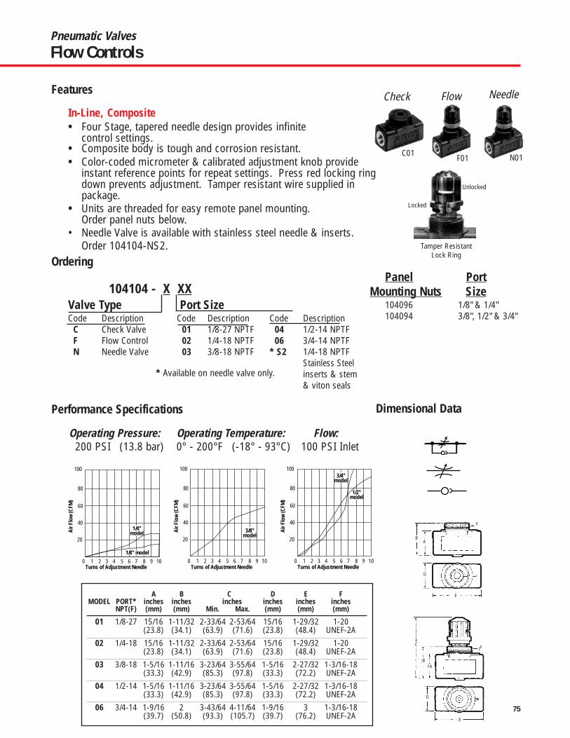
75
Pneumatic ValvesFlow Controls
100
80
60
40
20
0 1 2 3 4 5 6 7 8 9 10Turns of Adjustment Needle
Air F
low
(CFM
)
1/8" model
1/4"model
100
80
60
40
20
0 1 2 3 4 5 6 7 8 9 10Turns of Adjustment Needle
Air F
low
(CFM
)
3/8"model
100
80
60
40
20
0 1 2 3 4 5 6 7 8 9 10Turns of Adjustment Needle
Air F
low
(CFM
)
3/4"model
1/2"model
• Four Stage, tapered needle design provides infinite control settings.
• Composite body is tough and corrosion resistant.• Color-coded micrometer & calibrated adjustment knob provide
instant reference points for repeat settings. Press red locking ringdown prevents adjustment. Tamper resistant wire supplied inpackage.
• Units are threaded for easy remote panel mounting.Order panel nuts below.
• Needle Valve is available with stainless steel needle & inserts.Order 104104-NS2.
Operating Pressure: Operating Temperature: Flow:200 PSI (13.8 bar) 0° - 200°F (-18° - 93°C) 100 PSI Inlet
104104 - X XXValve Type Port SizeCode Description Code Description Code Description
C Check Valve 01 1/8-27 NPTF 04 1/2-14 NPTFF Flow Control 02 1/4-18 NPTF 06 3/4-14 NPTFN Needle Valve 03 3/8-18 NPTF * S2 1/4-18 NPTF
Stainless Steelinserts & stem& viton seals
A B C D E FMODEL PORT* inches inches inches inches inches inches
NPT(F) (mm) (mm) Min. Max. (mm) (mm) (mm)
01 1/8-27 15/16 1-11/32 2-33/64 2-53/64 15/16 1-29/32 1-20(23.8) (34.1) (63.9) (71.6) (23.8) (48.4) UNEF-2A
02 1/4-18 15/16 1-11/32 2-33/64 2-53/64 15/16 1-29/32 1-20(23.8) (34.1) (63.9) (71.6) (23.8) (48.4) UNEF-2A
03 3/8-18 1-5/16 1-11/16 3-23/64 3-55/64 1-5/16 2-27/32 1-3/16-18(33.3) (42.9) (85.3) (97.8) (33.3) (72.2) UNEF-2A
04 1/2-14 1-5/16 1-11/16 3-23/64 3-55/64 1-5/16 2-27/32 1-3/16-18(33.3) (42.9) (85.3) (97.8) (33.3) (72.2) UNEF-2A
06 3/4-14 1-9/16 2 3-43/64 4-11/64 1-9/16 3 1-3/16-18(39.7) (50.8) (93.3) (105.7) (39.7) (76.2) UNEF-2A
Panel PortMounting Nuts Size
104096 1/8" & 1/4"104094 3/8", 1/2" & 3/4"
AB
D
E
F
AB
C
D
E
F
F01C01
Tamper ResistantLock Ring
Locked
Unlocked
NeedleFlowCheck
* Available on needle valve only.
N01
In-Line, Composite
Features
Ordering
Performance Specifications Dimensional Data

76
Pneumatic ValvesFlow Controls
PORT “C” “D” “E” “F” “G” “H” “I” “J” “K”SIZE inches inches inches inches inches inches inches inches inches
“A” & “B” (mm) (mm) (mm) (mm) (mm) (mm) (mm) (mm) (mm)10/32 5/16 1/8 27/64 53/64 27/64 11/32 7/16 37/64 53/64
(8) (3.2) (11) (21) (11) (9) (11) (14.7) (21.1)
1/8 1/2 0 25/32 1-17/64 19/32 19/32 33/64 47/64 1-3/64(13) 0 (19.8) (32) (15) (15) (13) (18.5) (26.7)
1/4 43/64 0 1-1/64 1-39/64 3/4 3/4 23/32 7/8 1-19/64(17) 0 (25.8) (41) (19) (19) (18) (22.5) (32.9)
3/8 7/8 0 1-9/64 1-27/32 29/32 29/32 29/32 1-1/8 1-39/64(22) 0 (29) (47) (23) (23) (23) (28.5) 41
1/2 1-1/16 0 1-27/64 2-9/32 1-7/64 1-7/64 63/64 1-7/32 1-53/64(27) 0 (36) (58) (28) (28) (25) (31) (46.3)
1/8 33/64 0 25/32 1-7/8 19/32 19/32 33/64 47/64 1-3/64(13) 0 (19.8) (47.5) (15) (15) (13) (18.5) (26.7)
1/4 43/64 0 1-1/64 2-9/32 3/4 3/4 45/64 57/64 1-19/64(17) 0 (25.8) (58) (19) (19) (18) (22.5) (32.9)
3/8 7/8 0 1-9/64 2-37/64 29/32 29/32 29/32 1-1/8 1-39/64(22) 0 (29) (65.5) (23) (23) (23) (28.5) (41)
1/2 1-1/16 0 1-27/64 3-5/32 1-7/64 1-7/64 63/64 1-7/32 1-53/64(27) 0 (36) (80) (28) (28) (25) (31) (46.3)
KNOB
ADJ
UST
SLOT
TED
ADJU
ST
• 360° swivel eases tube alignment. Preapplied thread sealant eliminatesTeflon taping.
• Choose threaded or instant tube fitting inlets; slotted or knob flowadjustment.
• Sturdy components include nickel-plated brass body, black anodizedaluminum swivel, Buna-N seals and a stainless steel spring.
• Ready for installation on all ARO and competitive cylinders.• Consult factory for BSP size models.
SLOTTED ADJUST KNOB ADJUST119307-XXX 119309-XXX 119308-XXX 119310-XXX
Male x Female thd Male thd x fitting Male x Female thd Male thd x fittingDescription Description Description Description
XXX Male x Female xxx Male x Tubing xxx Male x Female XXX Male x Tubing103 10-32x10-32 103 10-32 x 5/32" 125 1/8" x 1/8" NPT 120 1/8" x 5/32"125 1/8" x 1/8" NPT 120 1/8" x 5/32" 250 1/4" x 1/4" NPT 125 1/8" x 1/4"250 1/4" x 1/4" NPT 125 1/8v x 1/4" 375 3/8" x 3/8" NPT 250 1/4" x 1/4"375 3/8" x 3/8" NPT 250 1/4" x 1/4" 500 1/2" x 1/2" NPT 255 1/4" x 3/8"500 1/2" x 1/2" NPT 255 1/4" x 3/8" 375 3/8" x 3/8"
375 3/8" x 3/8"
SLOTTED ADJUST
KNOB ADJUST
A
C
C
H
K
J
G
I
E
EF
A
B
Max. F
D
K
J
I
G
H
3
2
1
02 4 6 8 10 12
Turns of Adjustment Needle
Air F
low
(CFM
)
10-32model
35
30
25
20
15
10
5
02 4 6 8 10 12
Turns of Adjustment Needle
Air F
low
(CFM
)
1/4"model
1/8"model
140
120
100
80
60
40
20
02 4 6 8 10 12
Turns of Adjustment Needle
Air F
low
(CFM
)
1/2"model
3/8"model
Operating Pressure: 15-150 PSI (1-10 bar)Operating Temperature:-32°F - 158°F
Features
Ordering
Dimensional DataPerformance Specifications

77
Air System Components
Designed to remove rust, scale, condensed water and other debris fromcompressed air lines which may cause wear and premature failure of tools,valves, cylinders and other pneumatic equipment.
Standard Filters
1/8” & 1/4” Port - ARO Module/Air 1000 Series1/8” F25111-200 20 Micron 28 Polycarbonate/Guard 1.0 oz. Manual 200 PSIG1/4” F25121-200 20 Micron 38 Polycarbonate/Guard 1.0 oz. Manual 200 PSIG1/4” & 3/8” & 1/2” Port - ARO Module/Air 2000 Series1/4” F25221-110 40 Micron 54 Metal w/sight glass 6.0 oz. Manual 175 PSIG3/8” F25231-110 40 Micron 100 Metal w/sight glass 6.0 oz. Manual 175 PSIG1/2” F25241-110 40 Micron 122 Metal w/sight glass 6.0 oz. Manual 175 PSIG3/4” & 1” Port - ARO Super-Duty Series3/4” F25451-110 40 Micron 345 Metal w/sight glass 32 oz. Manual 250 PSIG1” F25461-110 40 Micron 345 Metal w/sight glass 32 oz. Manual 250 PSIG
* Air Flow is at 90 PSI Inlet and 5 PSI pressure drop.
Designed for paint spraying, instrumentation, controls and other applicationswhere the delivered air must be free of oil and fine particles. Effective inremoving 99.9% of oil aerosols. Also effective in removing debris particlesdown to .3 micron. Recommended for use in conjunction with an upstreamfilter to maximize the life of replacement element.
Coalescing Filters
1/8” & 1/4” Port - ARO Module/Air 1000 Series1/8” F25111-300 Coalescing 15 Polycarbonate 1.0 oz. Manual 200 PSIG1/4” F25121-300 Coalescing 17 Polycarbonate 1.0 oz. Manual 200 PSIG1/4” & 3/8” & 1/2” Port - ARO Module/Air 2000 Series1/4” F25221-310 Coalescing 40 Metal w/sight glass 6.0 oz. Manual 175 PSIG3/8” F25231-310 Coalescing 51 Metal w/sight glass 6.0 oz. Manual 175 PSIG1/2” F25241-310 Coalescing 53 Metal w/sight glass 6.0 oz. Manual 175 PSIG3/4” & 1” Port - ARO Super-Duty Series3/4” F25452-310 Coalescing 50 Metal w/sight glass 32 oz. Manual 250 PSIG1” F25462-310 Coalescing 150 Metal w/sight glass 32 oz. Manual 250 PSIG
* Air Flow is at 90 PSI Inlet and 5 PSI pressure drop.
Port Filter Flow* Bowl Max. InletSize Model Element cfm Bowl Size Drain Pressure
ARO Module/Air 1000 Series29660-2 20 Micron Element29586 Coalescing Element104257 Service Kit104264 Auto Drain Kit104258 Polycarbonate Bowl104259 Composite Bowl
ARO Module/Air 2000 Series100031-1 40 Micron Element100032 Coalescing Element104068 Auto Drain Kit104204 Metal w/sight glass104176 Service KitARO Super/Duty Series104119 40 Micron Element104231 Coalescing Element104116 Service Kit104068 Auto Drain104163 Sight Glass Kit
F25121-200
F25221-110
F25451-110
Port Filter Flow* Bowl Max. InletSize Model Element cfm Bowl Size Drain Pressure
Part Number Description Part Number Description
Ordering
Accessories
77
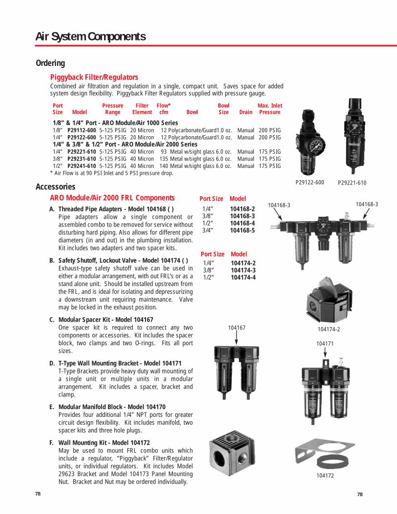
78
Air System Components
104172
P29122-600 P29221-610
Combined air filtration and regulation in a single, compact unit. Saves space for addedsystem design flexibility. Piggyback Filter Regulators supplied with pressure gauge.
Piggyback Filter/Regulators
ARO Module/Air 2000 FRL Components
1/8” & 1/4” Port - ARO Module/Air 1000 Series1/8” P29112-600 5-125 PSIG 20 Micron 12 Polycarbonate/Guard1.0 oz. Manual 200 PSIG1/4” P29122-600 5-125 PSIG 20 Micron 12 Polycarbonate/Guard1.0 oz. Manual 200 PSIG1/4” & 3/8” & 1/2” Port - ARO Module/Air 2000 Series1/4” P29221-610 5-125 PSIG 40 Micron 93 Metal w/sight glass 6.0 oz. Manual 175 PSIG3/8” P29231-610 5-125 PSIG 40 Micron 135 Metal w/sight glass 6.0 oz. Manual 175 PSIG1/2” P29241-610 5-125 PSIG 40 Micron 140 Metal w/sight glass 6.0 oz. Manual 175 PSIG
* Air Flow is at 90 PSI Inlet and 5 PSI pressure drop.
Port Pressure Filter Flow* Bowl Max. InletSize Model Range Element cfm Bowl Size Drain Pressure
A. Threaded Pipe Adapters - Model 104168 ( )Pipe adapters allow a single component orassembled combo to be removed for service withoutdisturbing hard piping. Also allows for different pipediameters (in and out) in the plumbing installation.Kit includes two adapters and two spacer kits.
B. Safety Shutoff, Lockout Valve - Model 104174 ( )Exhaust-type safety shutoff valve can be used ineither a modular arrangement, with out FRL’s or as astand alone unit. Should be installed upstream fromthe FRL, and is ideal for isolating and depressurizinga downstream unit requiring maintenance. Valvemay be locked in the exhaust position.
C. Modular Spacer Kit - Model 104167One spacer kit is required to connect any twocomponents or accessories. Kit includes the spacerblock, two clamps and two O-rings. Fits all portsizes.
D. T-Type Wall Mounting Bracket - Model 104171T-Type Brackets provide heavy duty wall mounting ofa single unit or multiple units in a modulararrangement. Kit includes a spacer, bracket andclamp.
E. Modular Manifold Block - Model 104170Provides four additional 1/4” NPT ports for greatercircuit design flexibility. Kit includes manifold, twospacer kits and three hole plugs.
F. Wall Mounting Kit - Model 104172May be used to mount FRL combo units whichinclude a regulator, “Piggyback” Filter/Regulatorunits, or individual regulators. Kit includes Model29623 Bracket and Model 104173 Panel MountingNut. Bracket and Nut may be ordered individually.
1/4” 104168-23/8” 104168-31/2” 104168-43/4” 104168-5
Port Size Model
Port Size Model
1/4” 104174-23/8” 104174-31/2” 104174-4
104168-3 104168-3
104174-2104167
104171
Ordering
Accessories
78

79
Air System Components
Provide controlled, consistent air pressure as required for specific pneumaticequipment connected to the compressed air system. Relieving models ventdownstream overpressure. Available spring options enable convenientpressure range conversions are requirements change. Unit supplied withgauge.
Air Line Relieving Regulators
Port Pressure Flow* Gauge Max. InletSize Model Range cfm Port Pressure
10006729850
R27121-600 R27221-600
27354-600
104172
ARO Module/Air 1000 SeriesPart Number Description29846 Gauge, 0-15 PSIG29863 Gauge, 0-60 PSIG29850 Gauge, 0-160 PSIG100095-160 Gauge, 0-150 PSIG29668 Mounting Bracket104094 Panel Mounting Nut104255 Service Kit, Relieving
Models
ARO Module/Air 2000 SeriesPart Number Description100067 Gauge, 0-160 PSIG104172 Wall Mount Kit (Includes
Bracket & Panel Nut)104173 Panel Mounting Nut104175 Tamper Resistant Kit104177 Service Kit, Relieving
Models29728 Gauge, 0-160 PSIG
Bottomport
ARO Heavy-Duty SeriesPart Number Description100067 Gauge, 0-160 PSIG100083 Gauge, 0-300 PSIG29960 Service Kit29077 Wall Mounting Bracket
1/8” & 1/4” Port - ARO Module/Air 1000 Series1/8” R27111-600 0-125 PSIG 13 1/8” 250 PSIG1/4” R27121-600 0-125 PSIG 13 1/8” 250 PSIG1/4” & 3/8” & 1/2” Port - ARO Module/Air Series1/4” R27221-600 5-125 PSIG 105 1/4” 200 PSIG3/8” R27231-600 5-125 PSIG 106 1/4” 200 PSIG1/2” R27241-600 5-125 PSIG 125 1/4” 200 PSIG1/2” & 3/4” & 1” Port - ARO Heavy-Duty Series1/2” 27344-600 5-125 PSIG 256 1/4” 250 PSIG3/4” 27354-600 5-125 PSIG 287 1/4” 250 PSIG1” 27364-600 5-125 PSIG 293 1/4” 250 PSIG
* Air Flow is at 90 PSI Inlet and 5 PSI pressure drop.
Accessories
Air Line Relieving Regulators
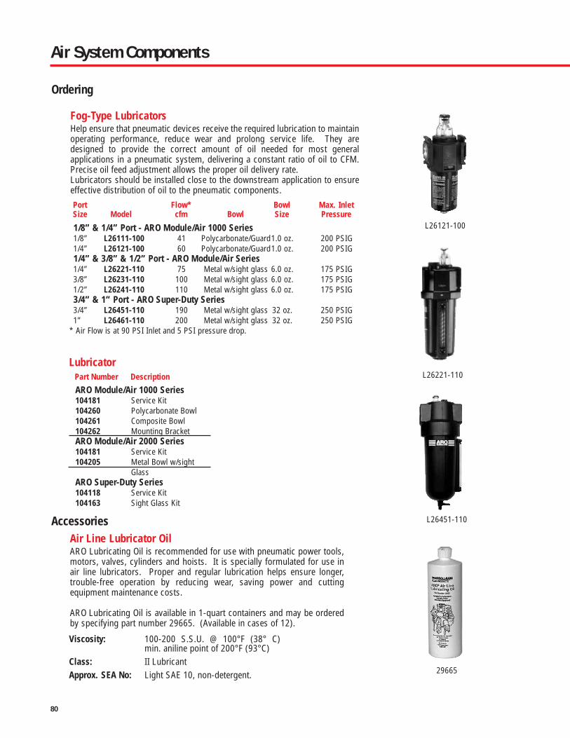
80
Lubricator
Help ensure that pneumatic devices receive the required lubrication to maintainoperating performance, reduce wear and prolong service life. They aredesigned to provide the correct amount of oil needed for most generalapplications in a pneumatic system, delivering a constant ratio of oil to CFM.Precise oil feed adjustment allows the proper oil delivery rate.Lubricators should be installed close to the downstream application to ensureeffective distribution of oil to the pneumatic components.
Fog-Type Lubricators
ARO Lubricating Oil is recommended for use with pneumatic power tools,motors, valves, cylinders and hoists. It is specially formulated for use inair line lubricators. Proper and regular lubrication helps ensure longer,trouble-free operation by reducing wear, saving power and cuttingequipment maintenance costs.
ARO Lubricating Oil is available in 1-quart containers and may be orderedby specifying part number 29665. (Available in cases of 12).
Air Line Lubricator Oil
1/8” & 1/4” Port - ARO Module/Air 1000 Series1/8” L26111-100 41 Polycarbonate/Guard1.0 oz. 200 PSIG1/4” L26121-100 60 Polycarbonate/Guard1.0 oz. 200 PSIG1/4” & 3/8” & 1/2” Port - ARO Module/Air Series1/4” L26221-110 75 Metal w/sight glass 6.0 oz. 175 PSIG3/8” L26231-110 100 Metal w/sight glass 6.0 oz. 175 PSIG1/2” L26241-110 110 Metal w/sight glass 6.0 oz. 175 PSIG3/4” & 1” Port - ARO Super-Duty Series3/4” L26451-110 190 Metal w/sight glass 32 oz. 250 PSIG1” L26461-110 200 Metal w/sight glass 32 oz. 250 PSIG
* Air Flow is at 90 PSI Inlet and 5 PSI pressure drop.
Port Flow* Bowl Max. InletSize Model cfm Bowl Size Pressure
ARO Module/Air 1000 Series104181 Service Kit104260 Polycarbonate Bowl104261 Composite Bowl104262 Mounting BracketARO Module/Air 2000 Series104181 Service Kit104205 Metal Bowl w/sight
GlassARO Super-Duty Series104118 Service Kit104163 Sight Glass Kit
Viscosity: 100-200 S.S.U. @ 100°F (38° C)min. aniline point of 200°F (93°C)
Class: II LubricantApprox. SEA No: Light SAE 10, non-detergent.
L26121-100
L26451-110
29665
Part Number Description L26221-110
Air System Components
Ordering
Accessories

81
WarningsHarmful Compressor Oils & Other Materials
Some oils used in air compressors contain chemicals harmful to Buna-N seals, if not adequately filtered atthe compressor. The most common of these oils, in addition to other harmful material, are listed below.
COMPRESSOR OILS COMPRESSOR OILS OTHER MATERIALS
Cellulube No. 150 & 220 Phrano Garlock No. 98403 (Polyurethane)
Haskel No. 568-023 Pydraul AC Parco No. 3106 (Neoprene)
Hougton & Co. Oil No. 1120, Sears Regular Motor Oil Some Loctite Compounds
No. 1130, No. 1055 Sinclair Oil “Lily White” Stillman No. SR269-75 (Polyurethane)
Houtosafe 1000 Skydrol Stillman No. SR513-70 (Neoprene)
Kano Kroil Tenneco Anderol No. 495
Keyston Penetrating Oil No. 2& No. 500 Oils
Marvel Mystery Oil
CAUTION: Compounded oilscontaining graphite and fillersare not recommended for usewith cylinders.
To obtain information or to receivetechnical literature for specific cylinders:contact ARO Customer Service at (800)495-0276 or contact your nearest AROdistributor. Selected parts are providedin kit form. The ARO Parts List/ServiceInstructions contain Repair Kitinformation and complete Service
Parts information and are availableupon request. Order Manuals as shown.The following Operator’s Manuals areavailable.
General Information
Air & Lubrication Requirement
AIR PRESSURE: Limited to 200 psig(14 bar) FILTRATION: 40 Micron.Proper moisture removal and filtrationof contaminates will promote goodservice life and operation. Install an airregulator to control the operatingpressure, insure smooth operation andconserve energy.LUBRICATION: All valve componentshave been lubricated at the factory andcan be operated without additional airline lubrication. Minimal lubricationmay extend the life of the valve. 50Series, E-Series and K-Series Valvesuse o-ring seals. For maximumperformance and life expectancy,standard air line lubrication should beused. If air line cylinders or other airline devices, used in conjunction withARO valve, require lubrication, be surethe lubricating oils used are compatiblewith the valve seals and are of sufficientviscosity to assure adequate lubrication.
ARO recommends an oil lubricant witha viscosity of 100-200 SUS at 100° Fand an airline point above 200° F.NOTICE: The use of compound oilscontaining graphite filters, extremelylow viscosities an other non-fluidlubricants is not recommended.RECOMMENDED: ARO 29665 air linelubricator oil is available in one quartcontainers.WarningThe following are hazards or unsafepractices which could result in severepersonal injury, death or substantialproperty damage. Heed the following.Use safeguards. Insure that provisionsare made to prevent the valve frombeing accidentally operated (actuated.)Hazardous Air Pressure. Shut off,disconnect and relieve any trapped airpressure from system beforeperforming service or maintenance.Hazardous Voltage. Do not attemptany service without disconnecting allelectrical supply sources.
Operator’s Manual Part NumberARO CYLINDERS 119999-27PROVENAIR 119999-30ECONOMAIR 119999-16MICROAIR 119999-41PREMAIR COMPACTS 119999-78PROVENAIR TANKS 119999-032
NOTICE: Genesis Series Valves mustbe grounded.Do not use the valve as a safety deviceor to operate or control the operation offull revolution clutch systems or brakesystems on power presses or similarequipment. These valves are notintended for such applications. Do notsubject the valve to any condition thatexceeds the limits set forth in thespecifications for a particular valvemodel. Keep all hoses, electrical wiring,fittings and connections in goodworking condition. Damaged airpressure hoses, electrical wiring, orconnections, could cause accidentalvalve operation (actuation). Only allowqualified technicians to install ormaintain the valve system. It isnecessary to have a throughunderstanding of the operation andapplication of all valves being used in aparticular system and how they interactwith the other components of thesystem.
WarningsGeneral Information

82
Cylinders Warranty
The ARO Cylinders, in this catalog are backed up by our famous 5-year warranty, as a measure of the confidence we place inthe quality of these products. A confidence that you can share.
FIVE-YEAR WARRANTY
Ingersoll Rand/ARO warrants to the original use purchaser of Ingersoll Rand/ARO manufactured cylinders that IngersollRand/ARO will repair or replace, free of charges, including return shipping costs within the Continental United States ofAmerica, any such product which under normal use and service proves defective in material or workmanship, as determinedby Ingersoll Rand/ARO Inspection, within FIVE YEARS from date of shipment from Ingersoll Rand/ARO, provided the claimeddefective product, or part thereof, is promptly returned to the Ingersoll Rand/ARO factory or Ingersoll Rand/ARO authorizedwarranty repair center with transportation prepaid.
This warranty does not cover failure of parts or components due to normal wear or damage, which in the judgment ofIngersoll Rand/ARO, arises from misuse, abrasion, corrosion, negligence, accident, substitution of non-Ingersoll Rand/AROparts, faulty installation or tampering.
If Ingersoll Rand/ARO Inspection discloses no defect in material or workmanship, repair or replacement and return will bemade at customary charges.
This warranty covers Ingersoll Rand/ARO manufactured products shipped on or after July 4, 1988.Equipment not covered by Ingersoll Rand/ARO warranty: accessories or components of equipment sold by Ingersoll
Rand/ARO that are not manufactured by Ingersoll Rand/ARO (such as switches, hoses, gasoline engines, etc.) are subject tothe warranty, if any, of their manufacturer. Ingersoll Rand/ARO will provide the purchaser with reasonable assistance in makingsuch claims.
The foregoing warranty supersedes, voids and is in lieu of all or any other warranties, express or implied, and no warranty ormerchantability or fitness for particular purpose is intended or made. Ingersoll Rand/ARO's sole obligation and the original usepurchaser's sole remedy is as stated above and in no event shall Ingersoll Rand/ARO be liable for any special, direct, indirect,incidental, consequential or other damages, or expenses of any nature including, without limitation, loss of profits or productiontime incurred by the original use purchaser or any other party.
Five Year Product Warranty

FORM 0611-M 0607 CPN 15266919 © 2007 Ingersoll Rand Company
Ingersoll Rand Industrial Technologies provides products, services, and solutions to enhance the
efficiency and productivity of our commercial, industrial, and process customers. Our innovative products
include air compressors, air systems components, tools, pumps, material and fluid handling systems
and microturbines.
www.irtools.com/aro