Embed Size (px)
Citation preview
Complex-Shape Metallic Aircraft Engine
Bracket Replacement Using Compression Molded
Discontinuous Long Fiber Thermoplastic Composites
Tim L. Greene
Christopher Wonderly, PE
M. Hakan Kilic, Ph.D
Bradley Keller
2Copyright 2015 by Greene, Tweed. Published by the Society for the Advancement of Material and Process Engineering with permission.
ABSTRACT
Compression molded Discontinuous Long Fiber (DLF) composites continue to see successful Aerospace adoption for metal replacement opportunities, providing a viable non-metallic option for cost-effective production of complex-shape components. Typically, DLF is used in applications where injection molding lacks sufficient performance and where use of traditional continuous fiber composite materials is impractical or impossible due to the complex component geometry.
Compared to metal, DLF composites provide particular benefits for structural brackets, fittings, or clips, including significant weight reductions and opportunities for parts consolidation to eliminate secondary assembly operations. DLF materials are produced by chopping high-fiber content, aerospace-qualified, unidirectional prepreg tape into “flakes” or “chips,” followed by compression molding into net or near-net shape composite components.
In a collaborative development effort between Greene Tweed and a major Aerospace engine manufacturer, the team proved the suitability of DLF brackets for production service on commercial aircraft engines using compression-molded carbon/PEEK thermoplastic composite DLF materials. Identification of functional requirements (including weight savings goals, design loads, and fastener torque/pullout expectations); redesign of the baseline multiple-piece metallic component into a single-piece DLF component; analysis and prediction of performance capability; manufacturing considerations; and compression molding of prototypes for mechanical testing will be presented herein. Results and conclusions from a validation test program for establishing conformance to requirements will also be outlined.
Complex-Shape Metallic Aircraft Engine Bracket Replacement Using Compression Molded Discontinuous Long Fiber Thermoplastic Composites
3Copyright 2015 by Greene, Tweed. Published by the Society for the Advancement of Material and Process Engineering with permission.
Composite materials continue to displace metal in new aerospace platforms due to recognized performance, life-cycle, and manufacturing advantages, with the Airbus A350 and Boeing 787 as two commercial aircraft examples demonstrating over 50% composite content [1, 2]. Composites are commonly specified for large primary and secondary structure applications based on cost-effective benefits from weight reduction, design freedom, and service life. However, many metallic components still remain on the aircraft, at least in part due to a product capability gap for metal-replacement of 3D complex-shape parts such as structural brackets, fittings, clips, or other components where injection molding lacks sufficient performance but use of traditional continuous fiber composite materials is impractical (or impossible) due to the complex component geometry.
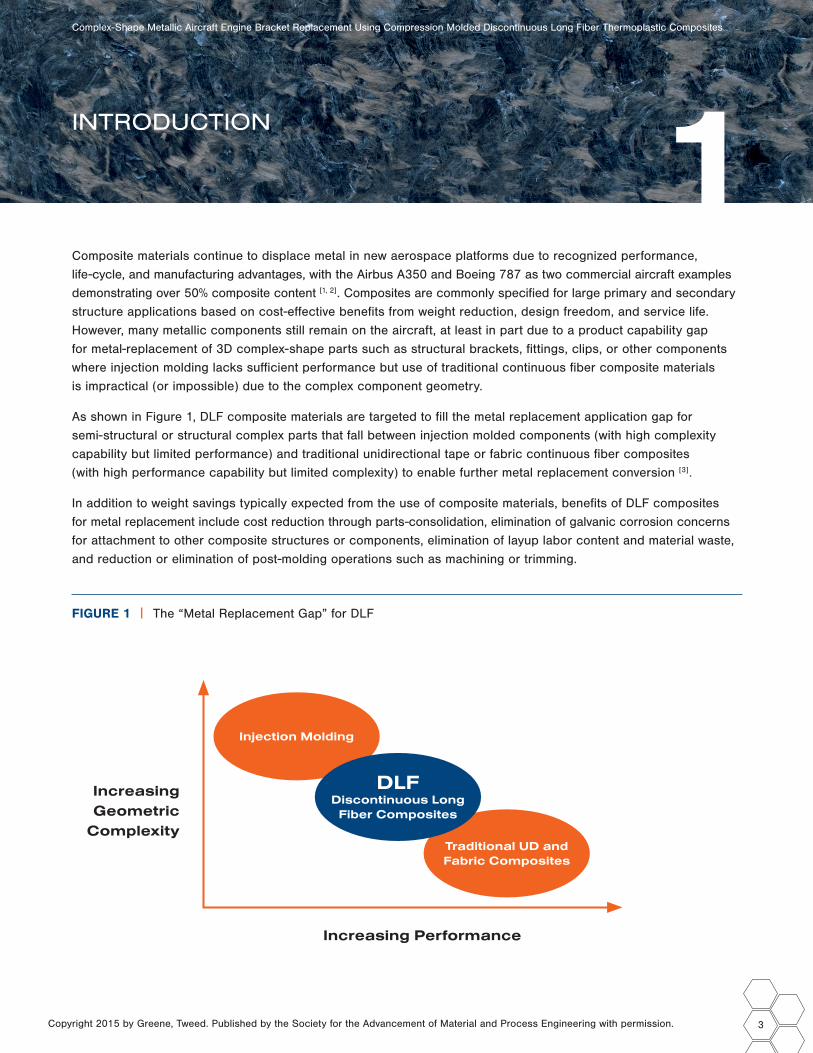
As shown in Figure 1, DLF composite materials are targeted to fill the metal replacement application gap for semi-structural or structural complex parts that fall between injection molded components (with high complexity capability but limited performance) and traditional unidirectional tape or fabric continuous fiber composites (with high performance capability but limited complexity) to enable further metal replacement conversion [3].
In addition to weight savings typically expected from the use of composite materials, benefits of DLF composites for metal replacement include cost reduction through parts-consolidation, elimination of galvanic corrosion concerns for attachment to other composite structures or components, elimination of layup labor content and material waste, and reduction or elimination of post-molding operations such as machining or trimming.
FIGURE 1 | The “Metal Replacement Gap” for DLF
Complex-Shape Metallic Aircraft Engine Bracket Replacement Using Compression Molded Discontinuous Long Fiber Thermoplastic Composites
1
Increasing Geometric
Complexity
Injection Molding
Increasing Performance
Traditional UD and Fabric Composites
DLFDiscontinuous Long
Fiber Composites
INTRODUCTION
4Copyright 2015 by Greene, Tweed. Published by the Society for the Advancement of Material and Process Engineering with permission.
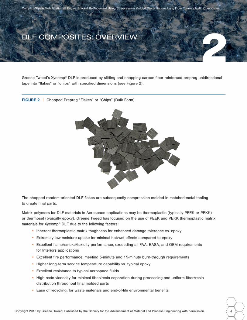
Greene Tweed’s Xycomp® DLF is produced by slitting and chopping carbon fiber reinforced prepreg unidirectional tape into “flakes” or “chips” with specified dimensions (see Figure 2).
FIGURE 2 | Chopped Prepreg “Flakes” or “Chips” (Bulk Form)
The chopped random-oriented DLF flakes are subsequently compression molded in matched-metal tooling to create final parts.
Matrix polymers for DLF materials in Aerospace applications may be thermoplastic (typically PEEK or PEKK) or thermoset (typically epoxy). Greene Tweed has focused on the use of PEEK and PEKK thermoplastic matrix materials for Xycomp® DLF due to the following factors:
• Inherent thermoplastic matrix toughness for enhanced damage tolerance vs. epoxy
• Extremely low moisture uptake for minimal hot/wet effects compared to epoxy
• Excellent flame/smoke/toxicity performance, exceeding all FAA, EASA, and OEM requirements for Interiors applications
• Excellent fire performance, meeting 5-minute and 15-minute burn-through requirements
• Higher long-term service temperature capability vs. typical epoxy
• Excellent resistance to typical aerospace fluids
• High resin viscosity for minimal fiber/resin separation during processing and uniform fiber/resin distribution throughout final molded parts
• Ease of recycling, for waste materials and end-of-life environmental benefits
Complex-Shape Metallic Aircraft Engine Bracket Replacement Using Compression Molded Discontinuous Long Fiber Thermoplastic Composites
2DLF COMPOSITES: OVERVIEW
5Copyright 2015 by Greene, Tweed. Published by the Society for the Advancement of Material and Process Engineering with permission.
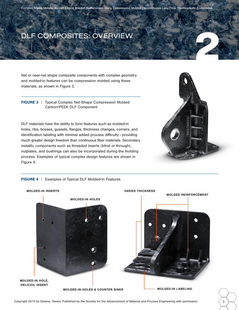
Net or near-net shape composite components with complex geometry and molded-in features can be compression molded using these materials, as shown in Figure 3.
FIGURE 3 | Typical Complex Net-Shape Compression Molded Carbon/PEEK DLF Component
DLF materials have the ability to form features such as molded-in holes, ribs, bosses, gussets, flanges, thickness changes, corners, and identification labeling with minimal added process difficulty–providing much greater design freedom than continuous fiber materials. Secondary metallic components such as threaded inserts (blind or through), nutplates, and bushings can also be incorporated during the molding process. Examples of typical complex design features are shown in Figure 4.
Complex-Shape Metallic Aircraft Engine Bracket Replacement Using Compression Molded Discontinuous Long Fiber Thermoplastic Composites
2
FIGURE 4 | Examples of Typical DLF Molded-In Features
MOLDED-IN HOLES & COUNTER SINKS
MOLDED-IN HOLES
MOLDED-IN HOLE,HELICOIL INSERT
MOLDED-IN INSERTS VARIED THICKNESS
MOLDED-IN LABELING
MOLDED REINFORCEMENT
Complex-Shape Metallic Aircraft Engine Bracket Replacement Using Compression Molded Discontinuous Long Fiber Thermoplastic Composites
2DLF COMPOSITES: OVERVIEW
6Copyright 2015 by Greene, Tweed. Published by the Society for the Advancement of Material and Process Engineering with permission.
Complex-Shape Metallic Aircraft Engine Bracket Replacement Using Compression Molded Discontinuous Long Fiber Thermoplastic Composites
BRACKET FUNCTIONALITY AND REQUIREMENTS
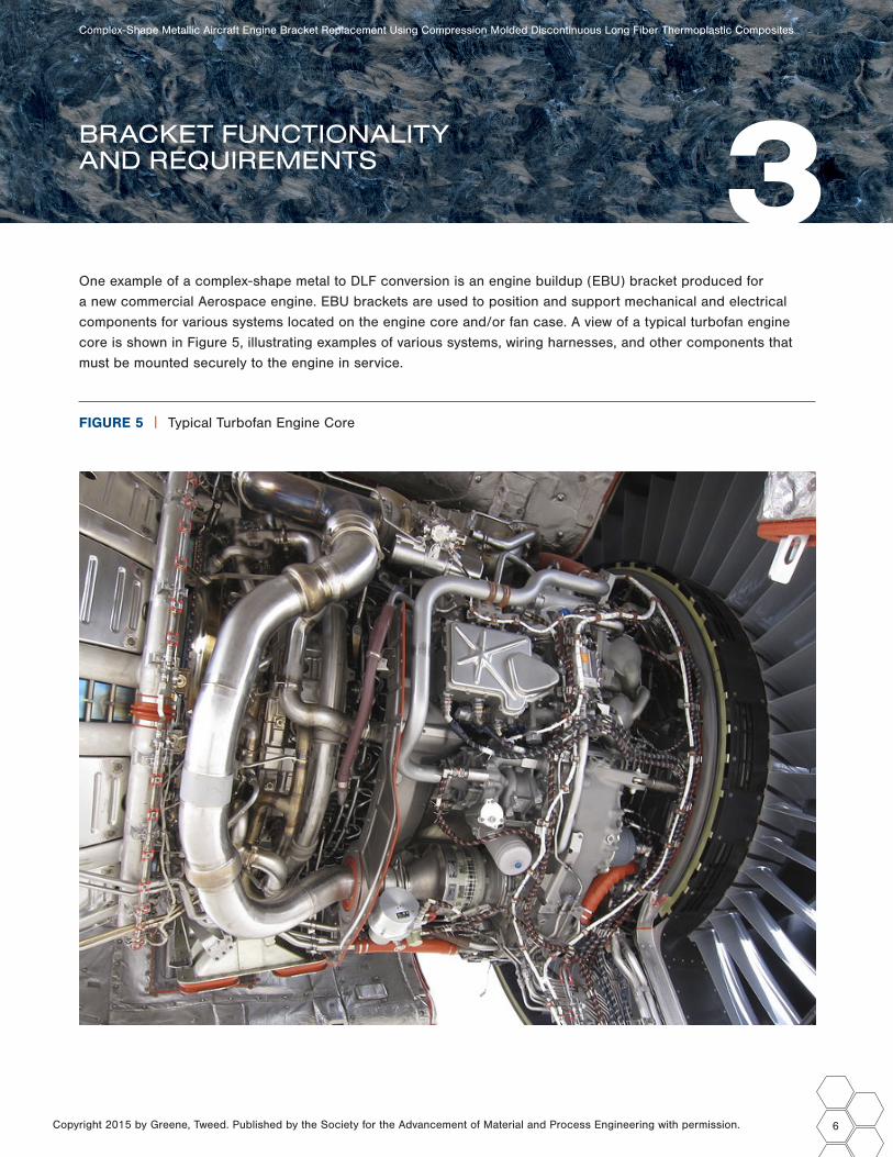
One example of a complex-shape metal to DLF conversion is an engine buildup (EBU) bracket produced for a new commercial Aerospace engine. EBU brackets are used to position and support mechanical and electrical components for various systems located on the engine core and/or fan case. A view of a typical turbofan engine core is shown in Figure 5, illustrating examples of various systems, wiring harnesses, and other components that must be mounted securely to the engine in service.
FIGURE 5 | Typical Turbofan Engine Core
3
7Copyright 2015 by Greene, Tweed. Published by the Society for the Advancement of Material and Process Engineering with permission.
Primary EBU bracket requirements include minimal weight, resistance to typical engine/aircraft fluids, and acceptable reliability while meeting various performance requirements, such as vibration, long-term service temperature, repeated cold/hot temperature cycling, and abuse loads.
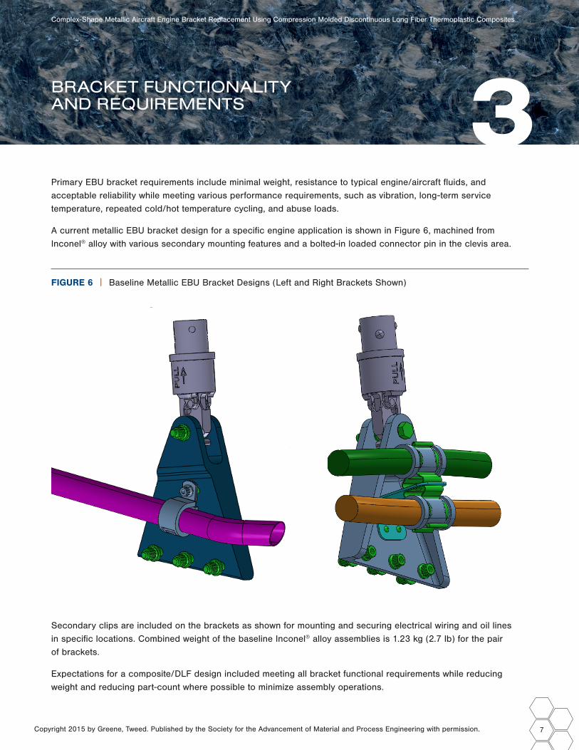
A current metallic EBU bracket design for a specific engine application is shown in Figure 6, machined from Inconel® alloy with various secondary mounting features and a bolted-in loaded connector pin in the clevis area.
FIGURE 6 | Baseline Metallic EBU Bracket Designs (Left and Right Brackets Shown)
Secondary clips are included on the brackets as shown for mounting and securing electrical wiring and oil lines in specific locations. Combined weight of the baseline Inconel® alloy assemblies is 1.23 kg (2.7 lb) for the pair of brackets.
Expectations for a composite/DLF design included meeting all bracket functional requirements while reducing weight and reducing part-count where possible to minimize assembly operations.
Complex-Shape Metallic Aircraft Engine Bracket Replacement Using Compression Molded Discontinuous Long Fiber Thermoplastic Composites
BRACKET FUNCTIONALITY AND REQUIREMENTS 3
8Copyright 2015 by Greene, Tweed. Published by the Society for the Advancement of Material and Process Engineering with permission.
Carbon/PEEK DLF materials were selected for designing the composite EBU brackets based on application requirements, availability of Greene Tweed and OEM material qualification approvals, and availability of carbon/PEEK DLF material allowables data for design use. The selected carbon/PEEK material incorporates standard modulus carbon fiber reinforcement and has the following nominal requirements:
• Unidirectional tape fiber areal weight of 145 gsm
• Unidirectional tape prepreg fiber volume 59 percent
• PEEK resin content 34 percent by weight
The unidirectional tape is supplied with certification to Greene Tweed and OEM material specifications, then subsequently slit and chopped per requirements to create DLF “flakes” for compression molding.
4.1 Design Considerations and Weight Savings
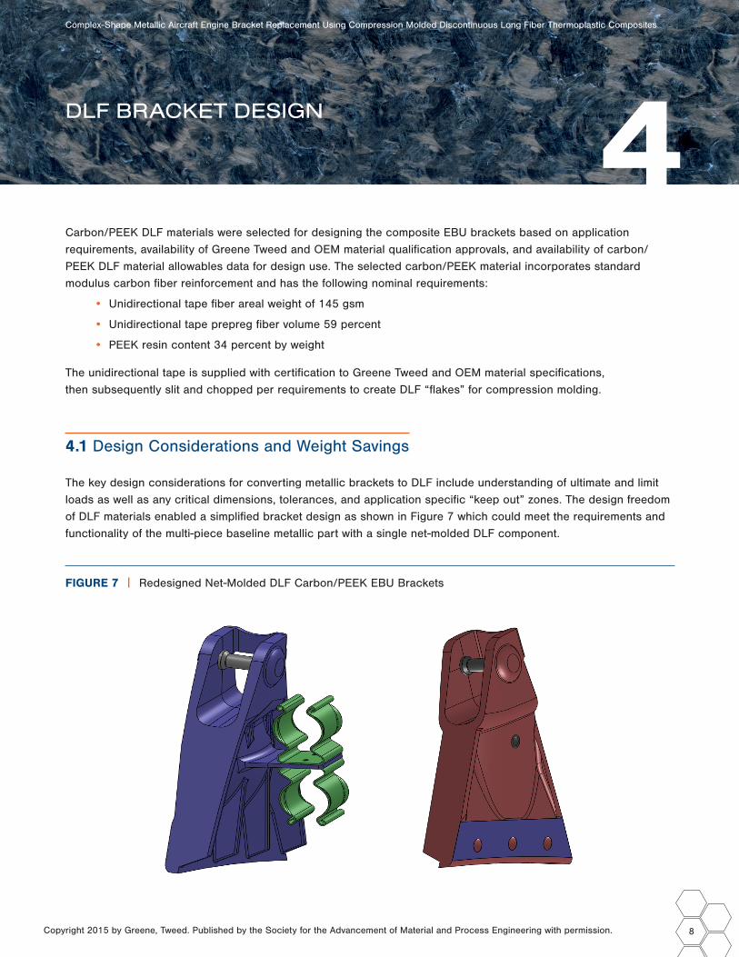
The key design considerations for converting metallic brackets to DLF include understanding of ultimate and limit loads as well as any critical dimensions, tolerances, and application specific “keep out” zones. The design freedom of DLF materials enabled a simplified bracket design as shown in Figure 7 which could meet the requirements and functionality of the multi-piece baseline metallic part with a single net-molded DLF component.
FIGURE 7 | Redesigned Net-Molded DLF Carbon/PEEK EBU Brackets
Complex-Shape Metallic Aircraft Engine Bracket Replacement Using Compression Molded Discontinuous Long Fiber Thermoplastic Composites
DLF BRACKET DESIGN 4

9Copyright 2015 by Greene, Tweed. Published by the Society for the Advancement of Material and Process Engineering with permission.
Provisions were incorporated for wiring harness clips and an oil line mounting hole, and both brackets incorporated a molded-in metallic latch pin to eliminate assembly and provide further weight reduction. The molded-in latch pin was also designed to prevent any axial or rotation movement in the bracket. Close collaboration with process and tooling engineers using Design for Manufacturing (DFM) principles throughout the design process ensured the resulting DLF designs were viable for full-scale production.
Since the carbon/PEEK brackets are attached to an aluminum interface, a fiberglass ply is also incorporated for galvanic isolation protection at the mating surface (shaded area in Figure 7 around the three fastener holes).
The redesigned pair of DLF composite EBU brackets saved a total weight of 1.05 kg (2.3 lb) or 86 percent vs. the original pair of Inconel® parts.
4.2 FE Analysis and Performance Predictions
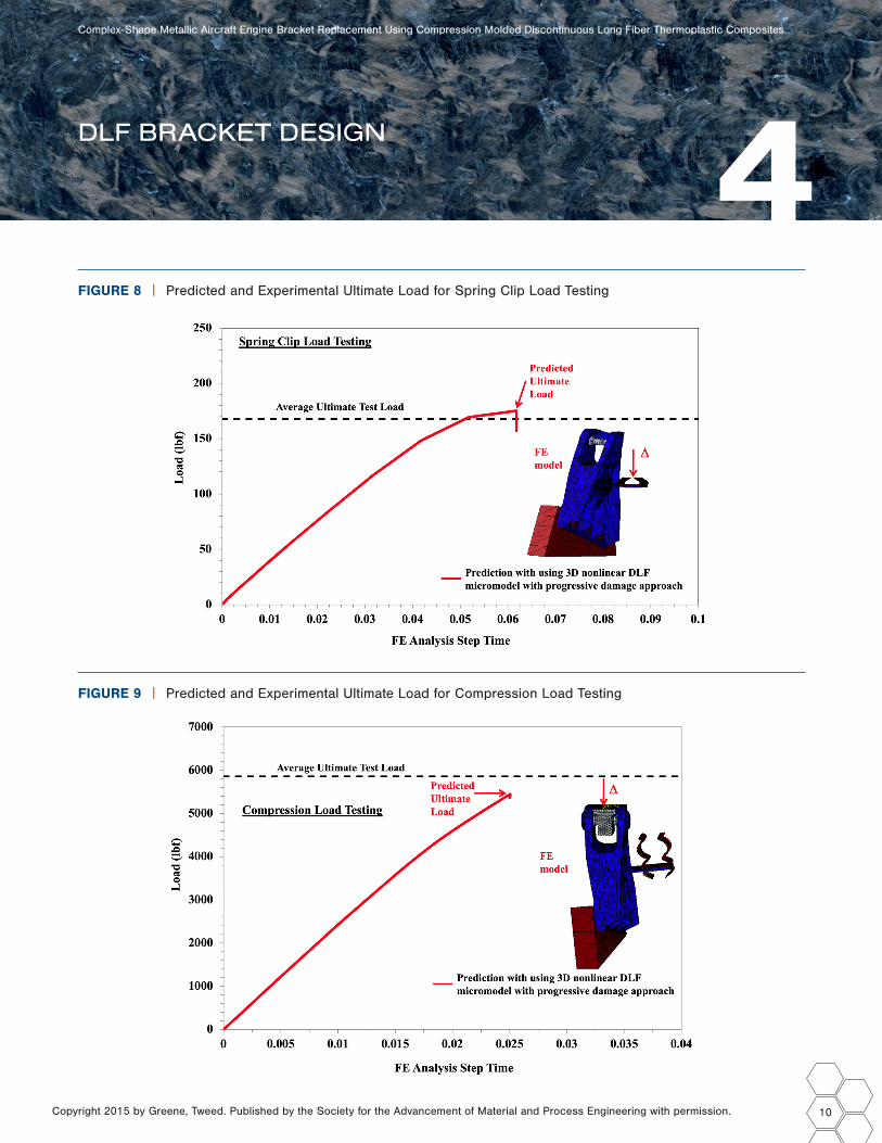
Greene Tweed has developed a 3D micromechanics-based nonlinear framework for the analysis of discontinuous long-fiber (DLF) thermoplastic composite materials and structures[4]. The overall modeling approach is able to predict both the elastic and nonlinear in-plane and out-of-plane responses of the composite material. A damage modeling approach is also used with the micromechanical model to form a framework for the progressive damage analysis of DLF composite structures. 3D Tsai-Wu failure criterion is used to detect damage initiation in the DLF material. The new “element deletion control by state variables” functionality in Abaqus/Standard version 6.14 is employed for the progressive damage analysis.
The analysis framework is used to predict the performance of DLF brackets under different loading conditions, as seen in Figures 8 through 10 (next page). The predicted ultimate loads using the 3D nonlinear micromodel along with the element deletion based progressive damage approach are compared with the experimental results. Good agreement is shown when comparing the experimental and the FE analysis results.
Complex-Shape Metallic Aircraft Engine Bracket Replacement Using Compression Molded Discontinuous Long Fiber Thermoplastic Composites
DLF BRACKET DESIGN 4
Greene Tweed has developed a 3D micromechanics-based nonlinear framework for the analysis of discontinuous long-fiber (DLF) thermoplastic composite materials and structures.4
10Copyright 2015 by Greene, Tweed. Published by the Society for the Advancement of Material and Process Engineering with permission.
FIGURE 8 | Predicted and Experimental Ultimate Load for Spring Clip Load Testing
FIGURE 9 | Predicted and Experimental Ultimate Load for Compression Load Testing
Complex-Shape Metallic Aircraft Engine Bracket Replacement Using Compression Molded Discontinuous Long Fiber Thermoplastic Composites
DLF BRACKET DESIGN 4
11Copyright 2015 by Greene, Tweed. Published by the Society for the Advancement of Material and Process Engineering with permission.
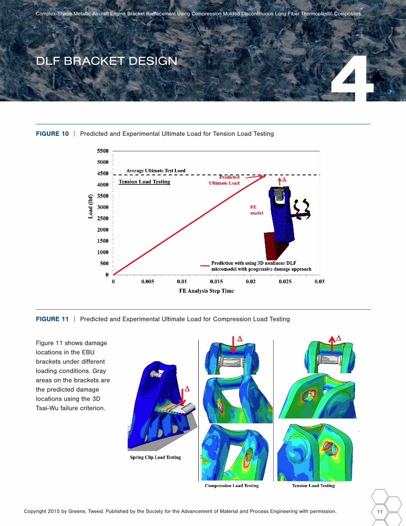
FIGURE 10 | Predicted and Experimental Ultimate Load for Tension Load Testing
FIGURE 11 | Predicted and Experimental Ultimate Load for Compression Load Testing
Complex-Shape Metallic Aircraft Engine Bracket Replacement Using Compression Molded Discontinuous Long Fiber Thermoplastic Composites
DLF BRACKET DESIGN 4
Figure 11 shows damage locations in the EBU brackets under different loading conditions. Gray areas on the brackets are the predicted damage locations using the 3D Tsai-Wu failure criterion.
12Copyright 2015 by Greene, Tweed. Published by the Society for the Advancement of Material and Process Engineering with permission.
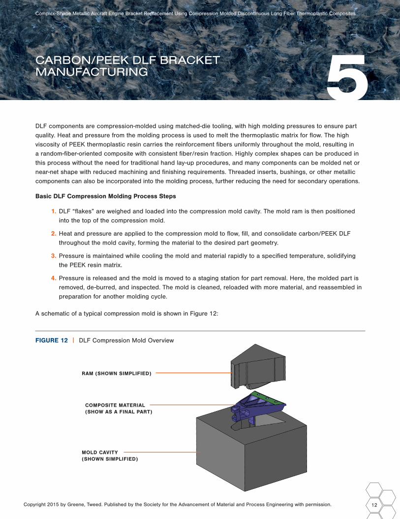
DLF components are compression-molded using matched-die tooling, with high molding pressures to ensure part quality. Heat and pressure from the molding process is used to melt the thermoplastic matrix for flow. The high viscosity of PEEK thermoplastic resin carries the reinforcement fibers uniformly throughout the mold, resulting in a random-fiber-oriented composite with consistent fiber/resin fraction. Highly complex shapes can be produced in this process without the need for traditional hand lay-up procedures, and many components can be molded net or near-net shape with reduced machining and finishing requirements. Threaded inserts, bushings, or other metallic components can also be incorporated into the molding process, further reducing the need for secondary operations.
Basic DLF Compression Molding Process Steps
1. DLF “flakes” are weighed and loaded into the compression mold cavity. The mold ram is then positioned into the top of the compression mold.
2. Heat and pressure are applied to the compression mold to flow, fill, and consolidate carbon/PEEK DLF throughout the mold cavity, forming the material to the desired part geometry.
3. Pressure is maintained while cooling the mold and material rapidly to a specified temperature, solidifying the PEEK resin matrix.
4. Pressure is released and the mold is moved to a staging station for part removal. Here, the molded part is removed, de-burred, and inspected. The mold is cleaned, reloaded with more material, and reassembled in preparation for another molding cycle.
A schematic of a typical compression mold is shown in Figure 12:
FIGURE 12 | DLF Compression Mold Overview
Complex-Shape Metallic Aircraft Engine Bracket Replacement Using Compression Molded Discontinuous Long Fiber Thermoplastic Composites
CARBON/PEEK DLF BRACKET MANUFACTURING 5
RAM (SHOWN SIMPLIFIED)
MOLD CAVITY (SHOWN SIMPLIFIED)
COMPOSITE MATERIAL (SHOW AS A FINAL PART)
13Copyright 2015 by Greene, Tweed. Published by the Society for the Advancement of Material and Process Engineering with permission.
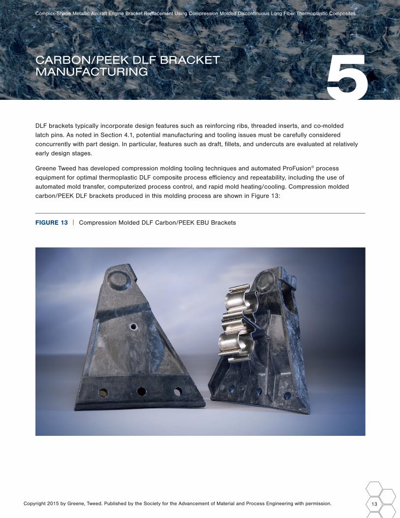
DLF brackets typically incorporate design features such as reinforcing ribs, threaded inserts, and co-molded latch pins. As noted in Section 4.1, potential manufacturing and tooling issues must be carefully considered concurrently with part design. In particular, features such as draft, fillets, and undercuts are evaluated at relatively early design stages.
Greene Tweed has developed compression molding tooling techniques and automated ProFusion® process equipment for optimal thermoplastic DLF composite process efficiency and repeatability, including the use of automated mold transfer, computerized process control, and rapid mold heating/cooling. Compression molded carbon/PEEK DLF brackets produced in this molding process are shown in Figure 13:
FIGURE 13 | Compression Molded DLF Carbon/PEEK EBU Brackets
Complex-Shape Metallic Aircraft Engine Bracket Replacement Using Compression Molded Discontinuous Long Fiber Thermoplastic Composites
CARBON/PEEK DLF BRACKET MANUFACTURING 5
14Copyright 2015 by Greene, Tweed. Published by the Society for the Advancement of Material and Process Engineering with permission.
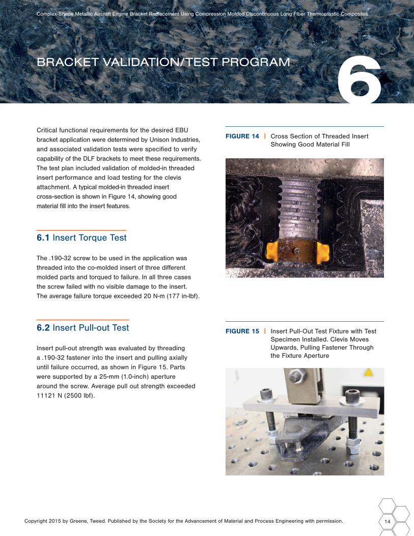
Critical functional requirements for the desired EBU bracket application were determined by Unison Industries, and associated validation tests were specified to verify capability of the DLF brackets to meet these requirements. The test plan included validation of molded-in threaded insert performance and load testing for the clevis attachment. A typical molded-in threaded insert cross-section is shown in Figure 14, showing good material fill into the insert features.
6.1 Insert Torque Test
The .190-32 screw to be used in the application was threaded into the co-molded insert of three different molded parts and torqued to failure. In all three cases the screw failed with no visible damage to the insert. The average failure torque exceeded 20 N-m (177 in-lbf).
6.2 Insert Pull-out Test
Insert pull-out strength was evaluated by threading a .190-32 fastener into the insert and pulling axially until failure occurred, as shown in Figure 15. Parts were supported by a 25-mm (1.0-inch) aperture around the screw. Average pull out strength exceeded 11121 N (2500 lbf).
FIGURE 14 | Cross Section of Threaded Insert Showing Good Material Fill
FIGURE 15 | Insert Pull-Out Test Fixture with Test Specimen Installed. Clevis Moves Upwards, Pulling Fastener Through the Fixture Aperture
Complex-Shape Metallic Aircraft Engine Bracket Replacement Using Compression Molded Discontinuous Long Fiber Thermoplastic Composites
BRACKET VALIDATION/TEST PROGRAM 6
15Copyright 2015 by Greene, Tweed. Published by the Society for the Advancement of Material and Process Engineering with permission.
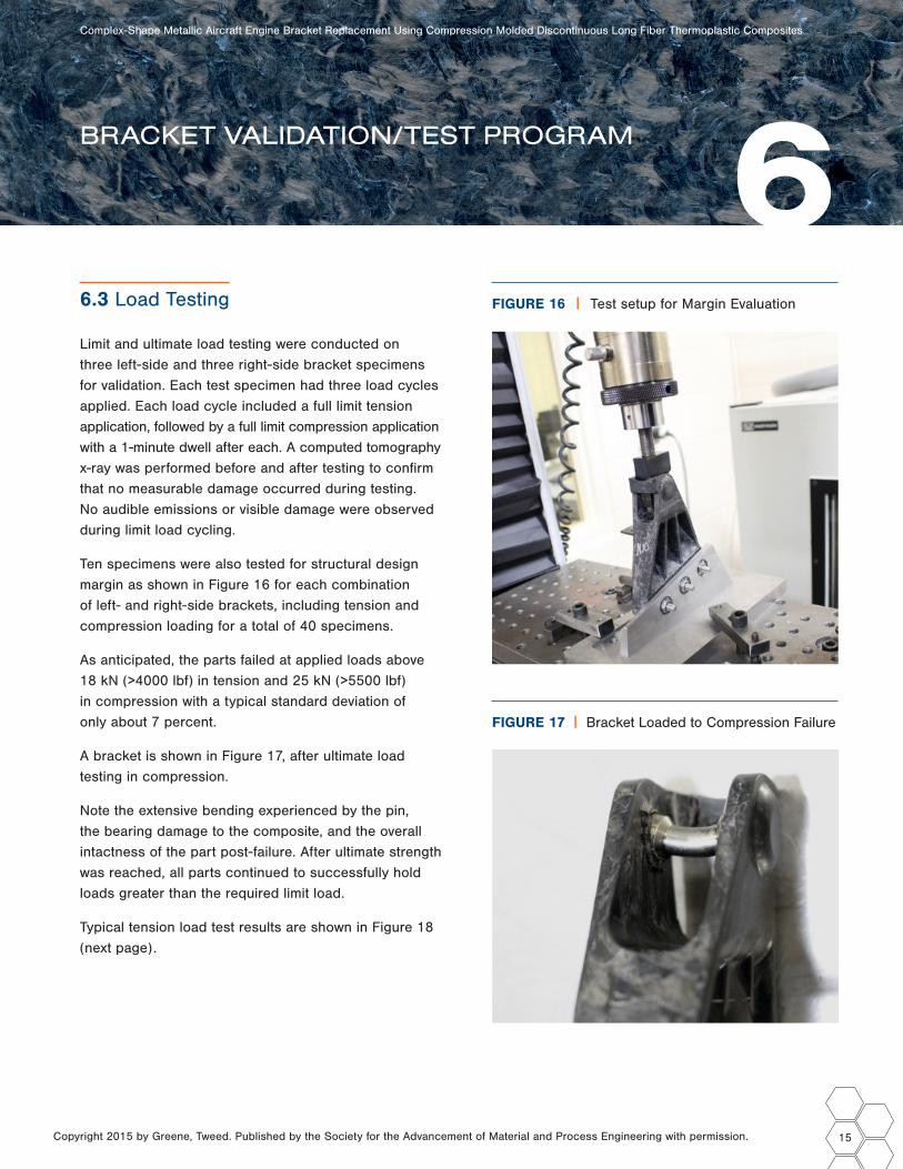
6.3 Load Testing
Limit and ultimate load testing were conducted on three left-side and three right-side bracket specimens for validation. Each test specimen had three load cycles applied. Each load cycle included a full limit tension application, followed by a full limit compression application with a 1-minute dwell after each. A computed tomography x-ray was performed before and after testing to confirm that no measurable damage occurred during testing. No audible emissions or visible damage were observed during limit load cycling.
Ten specimens were also tested for structural design margin as shown in Figure 16 for each combination of left- and right-side brackets, including tension and compression loading for a total of 40 specimens.
As anticipated, the parts failed at applied loads above 18 kN (>4000 lbf) in tension and 25 kN (>5500 lbf) in compression with a typical standard deviation of only about 7 percent.
A bracket is shown in Figure 17, after ultimate load testing in compression.
Note the extensive bending experienced by the pin, the bearing damage to the composite, and the overall intactness of the part post-failure. After ultimate strength was reached, all parts continued to successfully hold loads greater than the required limit load.
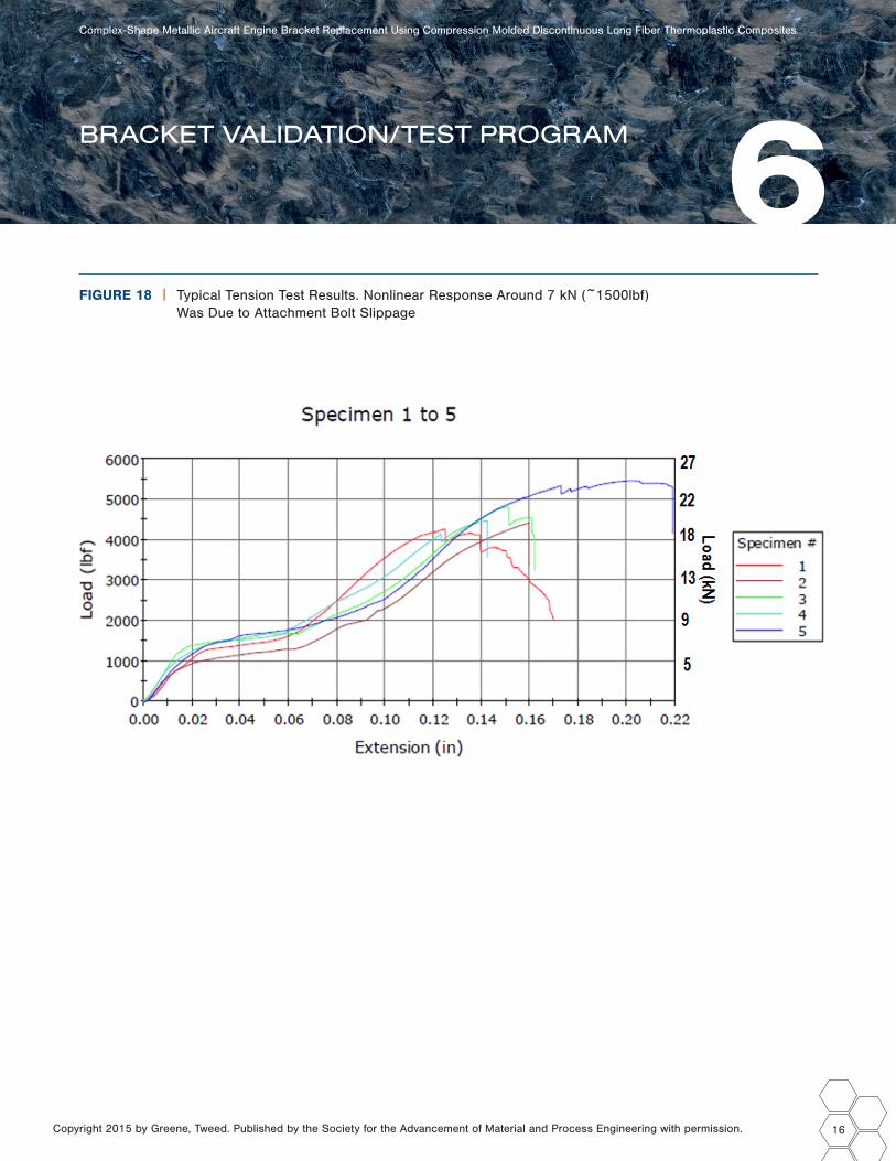
Typical tension load test results are shown in Figure 18 (next page).
FIGURE 16 | Test setup for Margin Evaluation
FIGURE 17 | Bracket Loaded to Compression Failure
Complex-Shape Metallic Aircraft Engine Bracket Replacement Using Compression Molded Discontinuous Long Fiber Thermoplastic Composites
BRACKET VALIDATION/TEST PROGRAM 6
16Copyright 2015 by Greene, Tweed. Published by the Society for the Advancement of Material and Process Engineering with permission.
FIGURE 18 | Typical Tension Test Results. Nonlinear Response Around 7 kN (~1500lbf) Was Due to Attachment Bolt Slippage
Complex-Shape Metallic Aircraft Engine Bracket Replacement Using Compression Molded Discontinuous Long Fiber Thermoplastic Composites
BRACKET VALIDATION/TEST PROGRAM 6
17Copyright 2015 by Greene, Tweed. Published by the Society for the Advancement of Material and Process Engineering with permission.
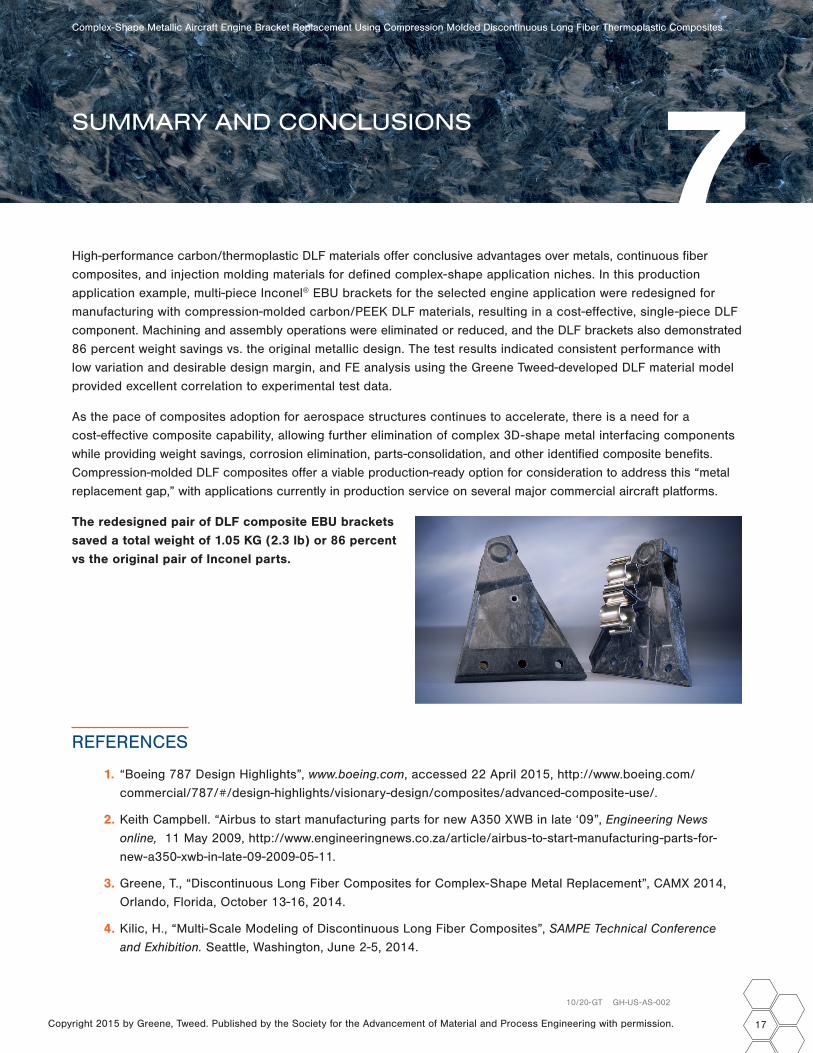
High-performance carbon/thermoplastic DLF materials offer conclusive advantages over metals, continuous fiber composites, and injection molding materials for defined complex-shape application niches. In this production application example, multi-piece Inconel® EBU brackets for the selected engine application were redesigned for manufacturing with compression-molded carbon/PEEK DLF materials, resulting in a cost-effective, single-piece DLF component. Machining and assembly operations were eliminated or reduced, and the DLF brackets also demonstrated 86 percent weight savings vs. the original metallic design. The test results indicated consistent performance with low variation and desirable design margin, and FE analysis using the Greene Tweed-developed DLF material model provided excellent correlation to experimental test data.
As the pace of composites adoption for aerospace structures continues to accelerate, there is a need for a cost-effective composite capability, allowing further elimination of complex 3D-shape metal interfacing components while providing weight savings, corrosion elimination, parts-consolidation, and other identified composite benefits. Compression-molded DLF composites offer a viable production-ready option for consideration to address this “metal replacement gap,” with applications currently in production service on several major commercial aircraft platforms.
The redesigned pair of DLF composite EBU brackets saved a total weight of 1.05 KG (2.3 lb) or 86 percent vs the original pair of Inconel parts.
REFERENCES
1. “Boeing 787 Design Highlights”, www.boeing.com, accessed 22 April 2015, http://www.boeing.com/commercial/787/#/design-highlights/visionary-design/composites/advanced-composite-use/.
2. Keith Campbell. “Airbus to start manufacturing parts for new A350 XWB in late ‘09”, Engineering News online, 11 May 2009, http://www.engineeringnews.co.za/article/airbus-to-start-manufacturing-parts-for-new-a350-xwb-in-late-09-2009-05-11.
3. Greene, T., “Discontinuous Long Fiber Composites for Complex-Shape Metal Replacement”, CAMX 2014, Orlando, Florida, October 13-16, 2014.
4. Kilic, H., “Multi-Scale Modeling of Discontinuous Long Fiber Composites”, SAMPE Technical Conference and Exhibition. Seattle, Washington, June 2-5, 2014.
Complex-Shape Metallic Aircraft Engine Bracket Replacement Using Compression Molded Discontinuous Long Fiber Thermoplastic Composites
SUMMARY AND CONCLUSIONS 7
10/20-GT GH-US-AS-002