Embed Size (px)
Citation preview
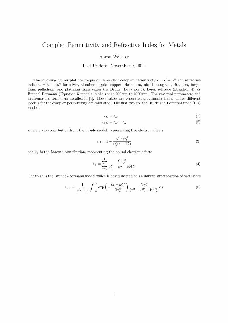
Complex Permittivity and Refractive Index for Metals
Aaron Webster
Last Update: November 9, 2012
The following figures plot the frequency dependent complex permittivity ε = ε′ + iε′′ and refractiveindex n = n′ + in′′ for silver, aluminum, gold, copper, chromium, nickel, tungsten, titanium, beryl-lium, palladium, and platinum using either the Drude (Equation 3), Lorentz-Drude (Equation 4), orBrendel-Bormann (Equation 5 models in the range 200 nm to 2000 nm. The material parameters andmathematical formalism detailed in [1]. These tables are generated programmatically. Three differentmodels for the complex permittivity are tabulated. The first two are the Drude and Lorentz-Drude (LD)models.
εD = εD (1)
εLD = εD + εL (2)
where εD is contribution from the Drude model, representing free electron effects
εD = 1−√f0 ω
′2p
ω(ω − iΓ′0)(3)
and εL is the Lorentz contribution, representing the bound electron effects
εL =
k∑j=0
fjω′2p
ω′2j − ω2 + iωΓ′j(4)
The third is the Brendel-Bormann model which is based instead on an infinite superposition of oscillators
εBB =1√
2π σn
∫ ∞−∞
exp
(− (x− ω′n)
2σ2n
)fjω
2p
(x2 − ω2) + iωΓ′ndx (5)
1
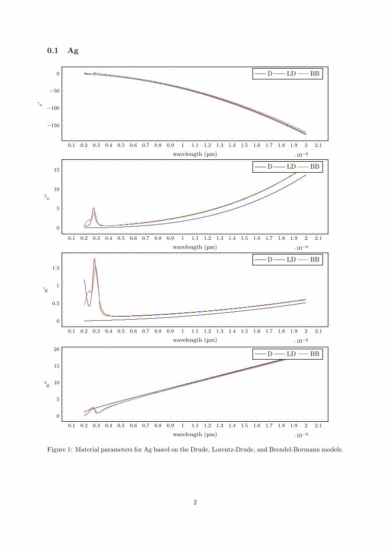
0.1 Ag
0.1 0.2 0.3 0.4 0.5 0.6 0.7 0.8 0.9 1 1.1 1.2 1.3 1.4 1.5 1.6 1.7 1.8 1.9 2 2.1
·10−6
−150
−100
−50
0
wavelength (µm)
ε′
D LD BB
0.1 0.2 0.3 0.4 0.5 0.6 0.7 0.8 0.9 1 1.1 1.2 1.3 1.4 1.5 1.6 1.7 1.8 1.9 2 2.1
·10−6
0
5
10
15
wavelength (µm)
ε′′
D LD BB
0.1 0.2 0.3 0.4 0.5 0.6 0.7 0.8 0.9 1 1.1 1.2 1.3 1.4 1.5 1.6 1.7 1.8 1.9 2 2.1
·10−6
0
0.5
1
1.5
wavelength (µm)
n′
D LD BB
0.1 0.2 0.3 0.4 0.5 0.6 0.7 0.8 0.9 1 1.1 1.2 1.3 1.4 1.5 1.6 1.7 1.8 1.9 2 2.1
·10−6
0
5
10
15
20
wavelength (µm)
n′′
D LD BB
Figure 1: Material parameters for Ag based on the Drude, Lorentz-Drude, and Brendel-Bormann models.
2
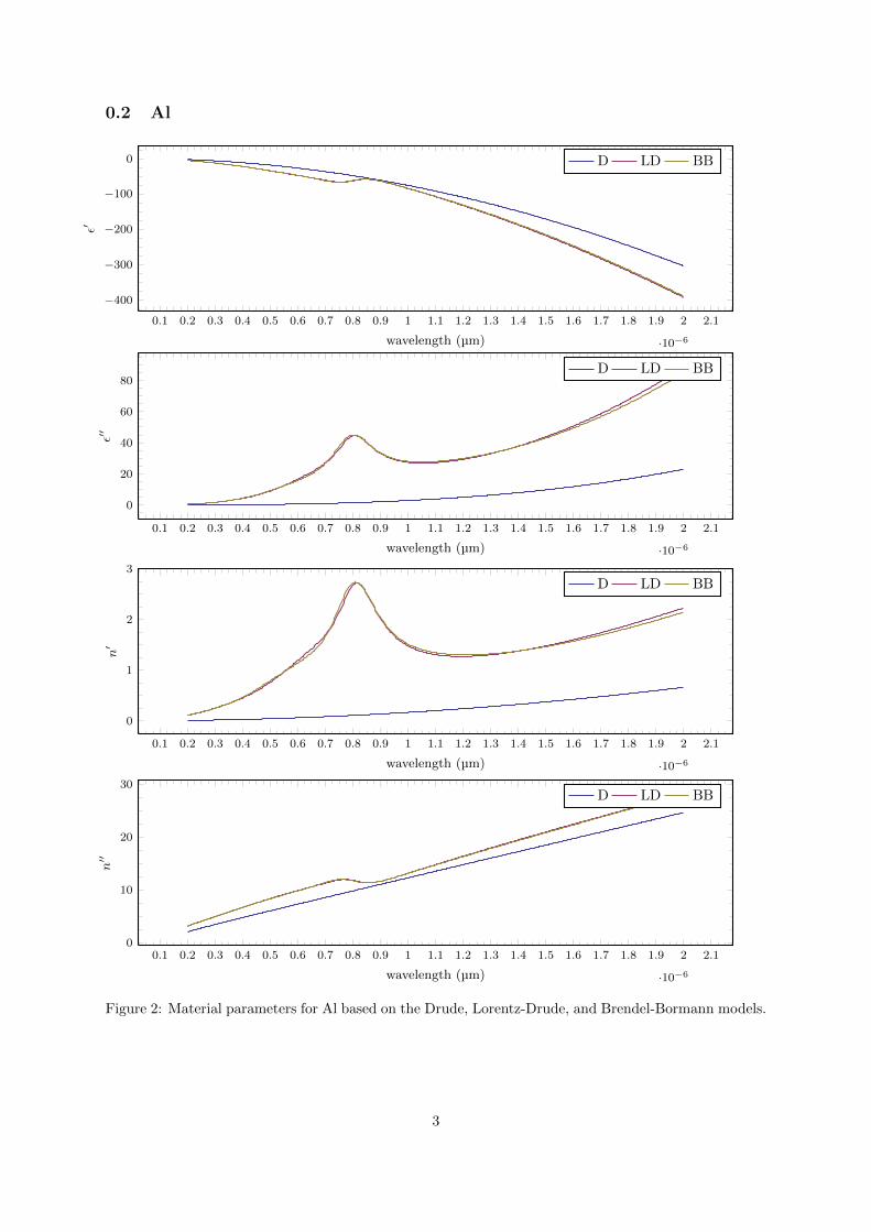
0.2 Al
0.1 0.2 0.3 0.4 0.5 0.6 0.7 0.8 0.9 1 1.1 1.2 1.3 1.4 1.5 1.6 1.7 1.8 1.9 2 2.1
·10−6
−400
−300
−200
−100
0
wavelength (µm)
ε′
D LD BB
0.1 0.2 0.3 0.4 0.5 0.6 0.7 0.8 0.9 1 1.1 1.2 1.3 1.4 1.5 1.6 1.7 1.8 1.9 2 2.1
·10−6
0
20
40
60
80
wavelength (µm)
ε′′
D LD BB
0.1 0.2 0.3 0.4 0.5 0.6 0.7 0.8 0.9 1 1.1 1.2 1.3 1.4 1.5 1.6 1.7 1.8 1.9 2 2.1
·10−6
0
1
2
3
wavelength (µm)
n′
D LD BB
0.1 0.2 0.3 0.4 0.5 0.6 0.7 0.8 0.9 1 1.1 1.2 1.3 1.4 1.5 1.6 1.7 1.8 1.9 2 2.1
·10−6
0
10
20
30
wavelength (µm)
n′′
D LD BB
Figure 2: Material parameters for Al based on the Drude, Lorentz-Drude, and Brendel-Bormann models.
3
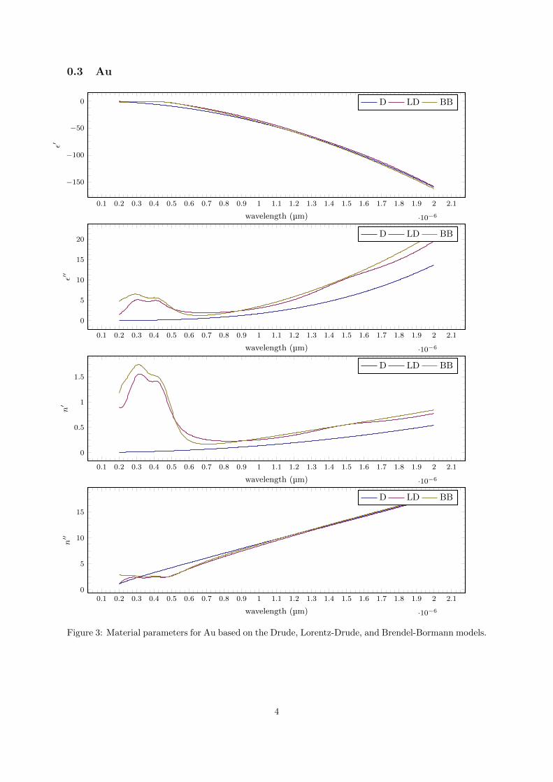
0.3 Au
0.1 0.2 0.3 0.4 0.5 0.6 0.7 0.8 0.9 1 1.1 1.2 1.3 1.4 1.5 1.6 1.7 1.8 1.9 2 2.1
·10−6
−150
−100
−50
0
wavelength (µm)
ε′
D LD BB
0.1 0.2 0.3 0.4 0.5 0.6 0.7 0.8 0.9 1 1.1 1.2 1.3 1.4 1.5 1.6 1.7 1.8 1.9 2 2.1
·10−6
0
5
10
15
20
wavelength (µm)
ε′′
D LD BB
0.1 0.2 0.3 0.4 0.5 0.6 0.7 0.8 0.9 1 1.1 1.2 1.3 1.4 1.5 1.6 1.7 1.8 1.9 2 2.1
·10−6
0
0.5
1
1.5
wavelength (µm)
n′
D LD BB
0.1 0.2 0.3 0.4 0.5 0.6 0.7 0.8 0.9 1 1.1 1.2 1.3 1.4 1.5 1.6 1.7 1.8 1.9 2 2.1
·10−6
0
5
10
15
wavelength (µm)
n′′
D LD BB
Figure 3: Material parameters for Au based on the Drude, Lorentz-Drude, and Brendel-Bormann models.
4
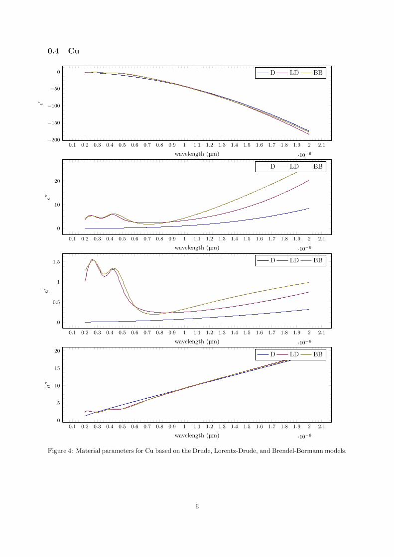
0.4 Cu
0.1 0.2 0.3 0.4 0.5 0.6 0.7 0.8 0.9 1 1.1 1.2 1.3 1.4 1.5 1.6 1.7 1.8 1.9 2 2.1
·10−6
−200
−150
−100
−50
0
wavelength (µm)
ε′
D LD BB
0.1 0.2 0.3 0.4 0.5 0.6 0.7 0.8 0.9 1 1.1 1.2 1.3 1.4 1.5 1.6 1.7 1.8 1.9 2 2.1
·10−6
0
10
20
wavelength (µm)
ε′′
D LD BB
0.1 0.2 0.3 0.4 0.5 0.6 0.7 0.8 0.9 1 1.1 1.2 1.3 1.4 1.5 1.6 1.7 1.8 1.9 2 2.1
·10−6
0
0.5
1
1.5
wavelength (µm)
n′
D LD BB
0.1 0.2 0.3 0.4 0.5 0.6 0.7 0.8 0.9 1 1.1 1.2 1.3 1.4 1.5 1.6 1.7 1.8 1.9 2 2.1
·10−6
0
5
10
15
20
wavelength (µm)
n′′
D LD BB
Figure 4: Material parameters for Cu based on the Drude, Lorentz-Drude, and Brendel-Bormann models.
5
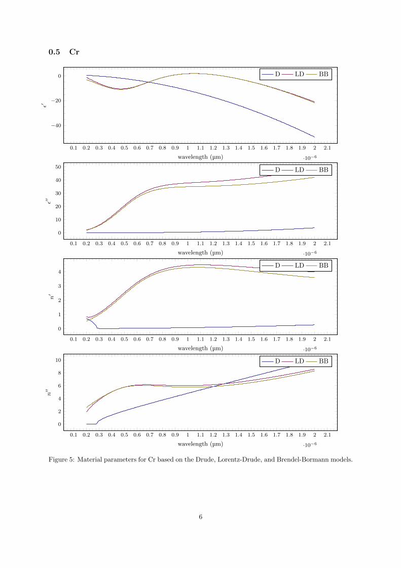
0.5 Cr
0.1 0.2 0.3 0.4 0.5 0.6 0.7 0.8 0.9 1 1.1 1.2 1.3 1.4 1.5 1.6 1.7 1.8 1.9 2 2.1
·10−6
−40
−20
0
wavelength (µm)
ε′
D LD BB
0.1 0.2 0.3 0.4 0.5 0.6 0.7 0.8 0.9 1 1.1 1.2 1.3 1.4 1.5 1.6 1.7 1.8 1.9 2 2.1
·10−6
0
10
20
30
40
50
wavelength (µm)
ε′′
D LD BB
0.1 0.2 0.3 0.4 0.5 0.6 0.7 0.8 0.9 1 1.1 1.2 1.3 1.4 1.5 1.6 1.7 1.8 1.9 2 2.1
·10−6
0
1
2
3
4
wavelength (µm)
n′
D LD BB
0.1 0.2 0.3 0.4 0.5 0.6 0.7 0.8 0.9 1 1.1 1.2 1.3 1.4 1.5 1.6 1.7 1.8 1.9 2 2.1
·10−6
0
2
4
6
8
10
wavelength (µm)
n′′
D LD BB
Figure 5: Material parameters for Cr based on the Drude, Lorentz-Drude, and Brendel-Bormann models.
6
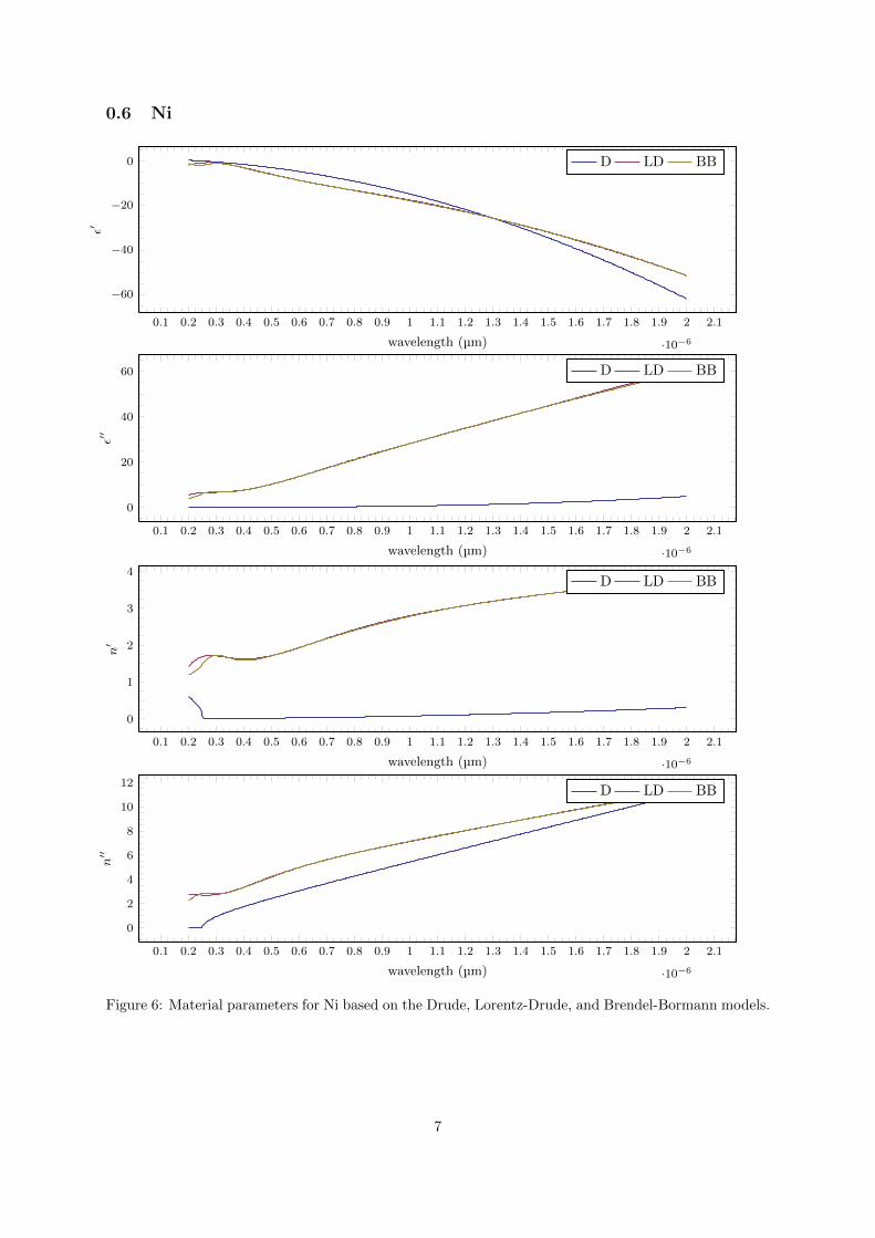
0.6 Ni
0.1 0.2 0.3 0.4 0.5 0.6 0.7 0.8 0.9 1 1.1 1.2 1.3 1.4 1.5 1.6 1.7 1.8 1.9 2 2.1
·10−6
−60
−40
−20
0
wavelength (µm)
ε′
D LD BB
0.1 0.2 0.3 0.4 0.5 0.6 0.7 0.8 0.9 1 1.1 1.2 1.3 1.4 1.5 1.6 1.7 1.8 1.9 2 2.1
·10−6
0
20
40
60
wavelength (µm)
ε′′
D LD BB
0.1 0.2 0.3 0.4 0.5 0.6 0.7 0.8 0.9 1 1.1 1.2 1.3 1.4 1.5 1.6 1.7 1.8 1.9 2 2.1
·10−6
0
1
2
3
4
wavelength (µm)
n′
D LD BB
0.1 0.2 0.3 0.4 0.5 0.6 0.7 0.8 0.9 1 1.1 1.2 1.3 1.4 1.5 1.6 1.7 1.8 1.9 2 2.1
·10−6
0
2
4
6
8
10
12
wavelength (µm)
n′′
D LD BB
Figure 6: Material parameters for Ni based on the Drude, Lorentz-Drude, and Brendel-Bormann models.
7
0.7 W
0.1 0.2 0.3 0.4 0.5 0.6 0.7 0.8 0.9 1 1.1 1.2 1.3 1.4 1.5 1.6 1.7 1.8 1.9 2 2.1
·10−6
−100
−80
−60
−40
−20
0
wavelength (µm)
ε′
D LD BB
0.1 0.2 0.3 0.4 0.5 0.6 0.7 0.8 0.9 1 1.1 1.2 1.3 1.4 1.5 1.6 1.7 1.8 1.9 2 2.1
·10−6
0
10
20
30
wavelength (µm)
ε′′
D LD BB
0.1 0.2 0.3 0.4 0.5 0.6 0.7 0.8 0.9 1 1.1 1.2 1.3 1.4 1.5 1.6 1.7 1.8 1.9 2 2.1
·10−6
0
1
2
3
4
wavelength (µm)
n′
D LD BB
0.1 0.2 0.3 0.4 0.5 0.6 0.7 0.8 0.9 1 1.1 1.2 1.3 1.4 1.5 1.6 1.7 1.8 1.9 2 2.1
·10−6
0
5
10
wavelength (µm)
n′′
D LD BB
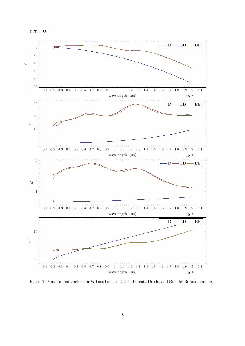
Figure 7: Material parameters for W based on the Drude, Lorentz-Drude, and Brendel-Bormann models.
8
0.8 Ti
0.1 0.2 0.3 0.4 0.5 0.6 0.7 0.8 0.9 1 1.1 1.2 1.3 1.4 1.5 1.6 1.7 1.8 1.9 2 2.1
·10−6
−20
−15
−10
−5
0
wavelength (µm)
ε′
D LD BB
0.1 0.2 0.3 0.4 0.5 0.6 0.7 0.8 0.9 1 1.1 1.2 1.3 1.4 1.5 1.6 1.7 1.8 1.9 2 2.1
·10−6
0
10
20
30
40
wavelength (µm)
ε′′
D LD BB
0.1 0.2 0.3 0.4 0.5 0.6 0.7 0.8 0.9 1 1.1 1.2 1.3 1.4 1.5 1.6 1.7 1.8 1.9 2 2.1
·10−6
0
1
2
3
4
wavelength (µm)
n′
D LD BB
0.1 0.2 0.3 0.4 0.5 0.6 0.7 0.8 0.9 1 1.1 1.2 1.3 1.4 1.5 1.6 1.7 1.8 1.9 2 2.1
·10−6
0
2
4
6
wavelength (µm)
n′′
D LD BB
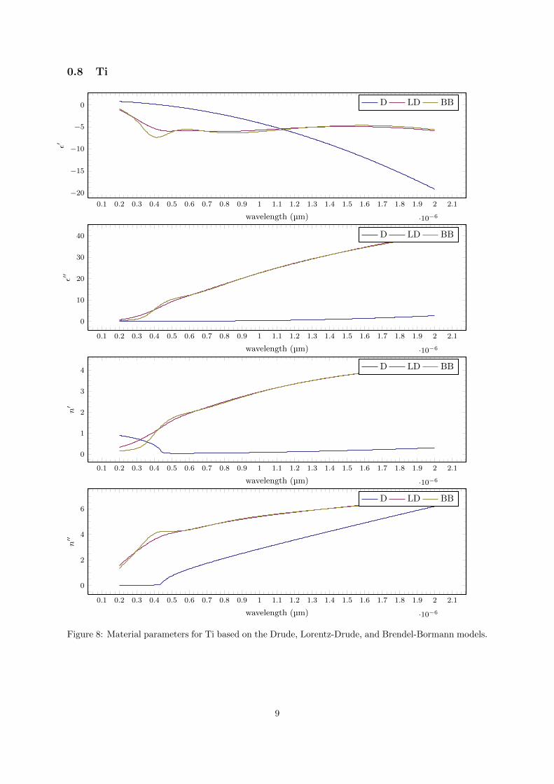
Figure 8: Material parameters for Ti based on the Drude, Lorentz-Drude, and Brendel-Bormann models.
9
0.9 Be
0.1 0.2 0.3 0.4 0.5 0.6 0.7 0.8 0.9 1 1.1 1.2 1.3 1.4 1.5 1.6 1.7 1.8 1.9 2 2.1
·10−6
−80
−60
−40
−20
0
wavelength (µm)
ε′
D LD BB
0.1 0.2 0.3 0.4 0.5 0.6 0.7 0.8 0.9 1 1.1 1.2 1.3 1.4 1.5 1.6 1.7 1.8 1.9 2 2.1
·10−6
0
10
20
30
40
wavelength (µm)
ε′′
D LD BB
0.1 0.2 0.3 0.4 0.5 0.6 0.7 0.8 0.9 1 1.1 1.2 1.3 1.4 1.5 1.6 1.7 1.8 1.9 2 2.1
·10−6
0
1
2
3
wavelength (µm)
n′
D LD BB
0.1 0.2 0.3 0.4 0.5 0.6 0.7 0.8 0.9 1 1.1 1.2 1.3 1.4 1.5 1.6 1.7 1.8 1.9 2 2.1
·10−6
0
5
10
wavelength (µm)
n′′
D LD BB
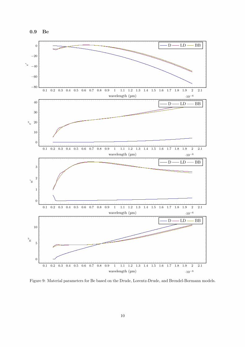
Figure 9: Material parameters for Be based on the Drude, Lorentz-Drude, and Brendel-Bormann models.
10
0.10 Pd
0.1 0.2 0.3 0.4 0.5 0.6 0.7 0.8 0.9 1 1.1 1.2 1.3 1.4 1.5 1.6 1.7 1.8 1.9 2 2.1
·10−6
−80
−60
−40
−20
0
wavelength (µm)
ε′
D LD BB
0.1 0.2 0.3 0.4 0.5 0.6 0.7 0.8 0.9 1 1.1 1.2 1.3 1.4 1.5 1.6 1.7 1.8 1.9 2 2.1
·10−6
0
20
40
60
80
wavelength (µm)
ε′′
D LD BB
0.1 0.2 0.3 0.4 0.5 0.6 0.7 0.8 0.9 1 1.1 1.2 1.3 1.4 1.5 1.6 1.7 1.8 1.9 2 2.1
·10−6
0
1
2
3
4
wavelength (µm)
n′
D LD BB
0.1 0.2 0.3 0.4 0.5 0.6 0.7 0.8 0.9 1 1.1 1.2 1.3 1.4 1.5 1.6 1.7 1.8 1.9 2 2.1
·10−6
0
5
10
15
wavelength (µm)
n′′
D LD BB
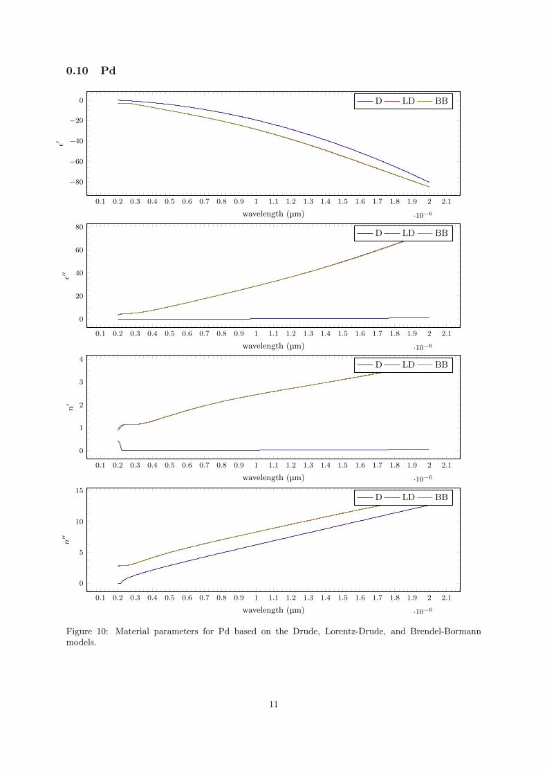
Figure 10: Material parameters for Pd based on the Drude, Lorentz-Drude, and Brendel-Bormannmodels.
11
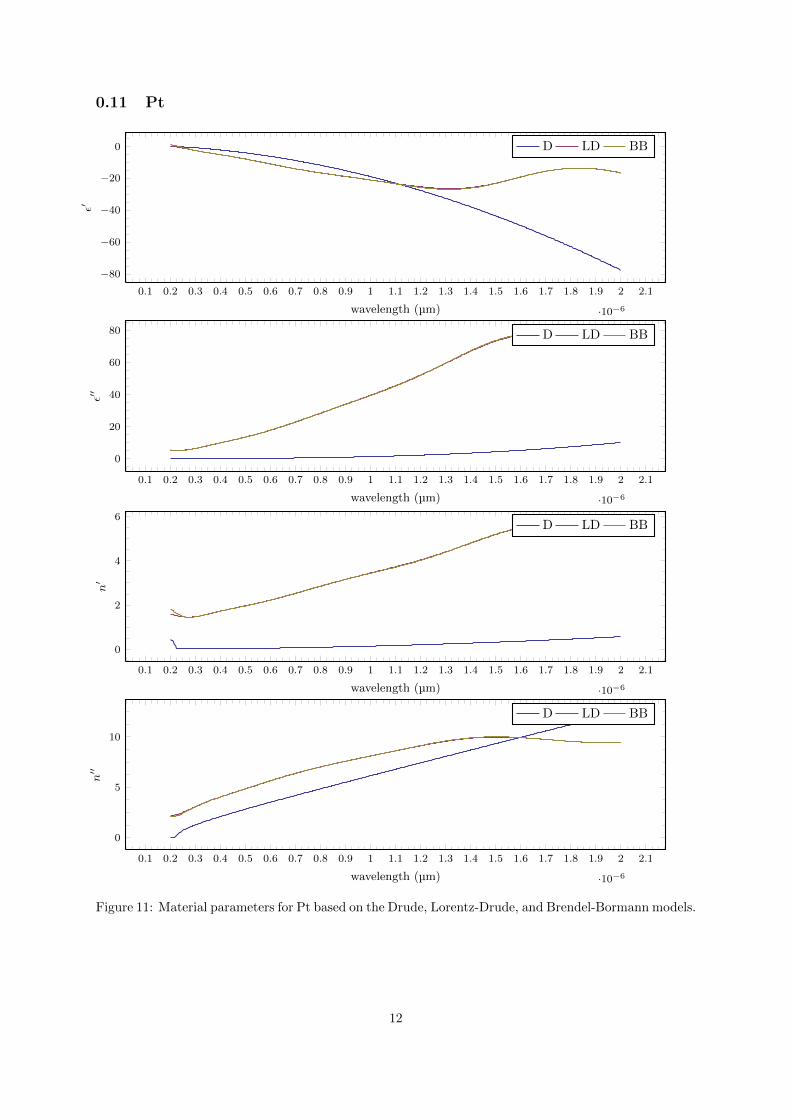
0.11 Pt
0.1 0.2 0.3 0.4 0.5 0.6 0.7 0.8 0.9 1 1.1 1.2 1.3 1.4 1.5 1.6 1.7 1.8 1.9 2 2.1
·10−6
−80
−60
−40
−20
0
wavelength (µm)
ε′
D LD BB
0.1 0.2 0.3 0.4 0.5 0.6 0.7 0.8 0.9 1 1.1 1.2 1.3 1.4 1.5 1.6 1.7 1.8 1.9 2 2.1
·10−6
0
20
40
60
80
wavelength (µm)
ε′′
D LD BB
0.1 0.2 0.3 0.4 0.5 0.6 0.7 0.8 0.9 1 1.1 1.2 1.3 1.4 1.5 1.6 1.7 1.8 1.9 2 2.1
·10−6
0
2
4
6
wavelength (µm)
n′
D LD BB
0.1 0.2 0.3 0.4 0.5 0.6 0.7 0.8 0.9 1 1.1 1.2 1.3 1.4 1.5 1.6 1.7 1.8 1.9 2 2.1
·10−6
0
5
10
wavelength (µm)
n′′
D LD BB
Figure 11: Material parameters for Pt based on the Drude, Lorentz-Drude, and Brendel-Bormann models.
12
References
[1] A.D. Rakic, A.B. Djurisic, J.M. Elazar, and M.L. Majewski. Optical properties of metallic films forvertical-cavity optoelectronic devices. Applied Optics, 37(22):5271–5283, 1998.
13