Embed Size (px)
Citation preview

177www.swegon.comWe reserve the right to alter specifications.
GOLD
20110601
Complements and Accessories
Chillers/heat pumps .........................................................................................................178COOL DX/COOL DX Top Cooling unit ........................................................................................................178 Blue Box Chiller/Heat pump .......................................................................................................................185
Air handling unit section .................................................................................................186TCBR Air recirculation section ....................................................................................................................186 TCBP Bypass section ....................................................................................................................................187
Duct Accessories ...............................................................................................................188Uninsulated ................................................................................................................................................188In insulated casing .....................................................................................................................................205
Roof hoods and exterior wall hoods ..............................................................................241
Component box ...............................................................................................................242
Outdoor installation ........................................................................................................243
Mechanical Equipment ....................................................................................................244
Communication ................................................................................................................246
Electrical and Control Equipment ...................................................................................247
Contents

178
GOLD
www.swegon.comWe reserve the right to alter specifications. 20110601
Plug and Play with COOL DX!
Extremely quick and simple installation.
Built-in control equipment operated from the GOLD.
Variable comfort control or economy control in 3 steps.
Cooling capacity
Tem
per
atu
re r
edu
ctio
n
Economy or comfort controlEconomy controlCooling in 3 stepsWhen cooling is required, cooling compressor 1 starts up. On an increasing ccoling load, cooling compressor 2 starts up and cooling compressor 1 is switched out. If the cool-ing load increases even more, both cooling compressors are started.
Advantage: Each cooling compressor is switched in and out in pace with the amount of cooling required and this shortens the overall in-operation period.
Consequence: Cooling in 3 steps
Comfort control (not COOL DX Top)Cooling and variable temperature controlAs a form of economy control but when there is a cooling load, the heat exchanger of the air handling unit is also activated and this controls the temperature within the cooling step.
Advantage: Variable control of the cooling capacity and uniform supply air temperature.
Consequence: Each cooling compressor operates for a longer period when cooling is needed.
Cooling capacity
Tem
per
atu
re r
edu
ctio
n
Cooling compressor Heat exchanger
Ready for communication via the GOLD.
Its location inside the GOLD prevents the extract air fan motor from being subject to
high temperatures.
The CoolDX Top cooling unit fits in well in the concept of the GOLD air handling unit and really stands for Plug and Play.
All the equipment is housed in one and the same unit and can be docked to the GOLD. The COOL DX can also be installed as a stand-alone unit.
In addition to the above, only an electric power supply and a communication cable (with quick-fit connector)
between the COOL DX/COOL DX Top and the GOLD as well as the connection of drainage pipework are required.
The GOLD has ready-to-use cooling functions for control-ling and regulating the COOL DX/COOL DX Top. This also includes communication via web or traditional perfor-mance monitoring systems.
The COOL DX/COOL DX Top thus means minimal invest-ment for project designing, procurement and installation.
Dock the COOL DX Top on top of the GOLD RX Top air handling unitDock the COOL DX to the GOLD air handling unit

179www.swegon.comWe reserve the right to alter specifications.
GOLD
20110601
COOL DX/COOL DX Top
Complements and Accessories
GeneralThe COOL DX/COOL DX Top is a complete cooling unit for comfort cooling in the air handling system.
The COOL DX is produced in seven sizes with cooling capacity from 10 to 134 kW. The seven sizes are capacity-wise matched to the size 07-80 GOLD air handling units.
The COOL DX Top is produced in three sizes with cooling capacity from 6.8 to 20.4 kW. On the basis of capacity, the three sizes are matched to the size 04 - 12 GOLD air handling units.
Mechanical DesignThe COOL DX cooling unit is designed for installation against the outdoor air and exhaust air side of the GOLD unit.
Place the COOL DX Top cooling unit on top of the GOLD RX Top air handling unit
All electrical and control equipment is prewired and col-lected inside a common casing.
The panels are of sandwich design consisting of a galva-nized sheet metal outer skin (0.7 mm thick), visible sur-faces are painted (NCS S2005-Y30R), an aluminium-zinc plated sheet metal inner skin (1 mm thick) and mineral wool insulation (50 mm thick) in between.
The cooling coil and condenser are fabricated of copper tubing and profiled aluminium fins.
The cooling unit is test run prior to delivery.
Control and regulationThe COOL DX/COOL DX Top cooling unit has a built-in control system.
Only an electric power supply and a communication cable are required for the transmission of information between the COOL DX/COOL DX Top and the GOLD control sys-tems. The communication cable is supplied together with the unit. All in-operation status and other information is readily available for viewing in the hand-held terminal of the GOLD air handling unit.
The cooling capacity is controlled by operating one or both compressors. Cooling is controlled in 3 steps in binary mode.
On receiving an on/off control signal, compressor M1 starts up. On an increasing cooling load, compressor M2 starts at the same time that compressor M1 stops. If the cooling load increases even more, both compressors M1 and M2 operate.
Completely direct-acting systemThe COOL DX/COOL DX Top has a completely direct-acting system. It has an evaporation coil for direct-evapo-rating refrigerant on the cold side and a condenser coil on the hot side.
RefrigerantThe COOL DX/COOL DX Top has double refrigerant circuits, which are charged with refrigerant on delivery. The volume of refrigerant for each size is tabulated in the Technical Data Table.
Type R410A refrigerant is used. At present, this refriger-ant has no known influence on the ozone layer and no known future restrictions are anticipated.
Initial inspection of the installation, obligation to report volumes of refrigerant charged/known leakage, and pe-riodic inspection may in some cases be required by local supervisory authorities.
Duct connectionThe end connection panel for outdoor and/or exhaust air is optional for the Cool DX cooling units. If an end con-nection panel is selected, slip-clamps (sizes 20-80) or rub-ber ring seals (sizes 08-12) are used for connection to the ducting. If no end connection panel has been selected, the profiled frame members on the cooling unit should be connected to the ducting across an adapter (not supplied by Swegon).
Connect the COOL DX Top to duct connections with rubber seal ring.
COOL DX
COOL DX Top

180
GOLD
www.swegon.comWe reserve the right to alter specifications. 20110601
Complements and Accessories
Sizing in ProUnitThere are many factors that influence what size of cooling unit is required. For correct sizing we refer to our ProUnit air handling unit selection program.
COOL DXSize
Capa-city vari-ant
Nom. air-
flow, m3/s
Min. air-
flow, m3/s
Nom. cooling
capacity1)
(kW)
Nom. Power
required(kW)
Refrigerant (kg)
Power supply
Weight excl. end
conn. panel(kg)
Weight of each end
conn. panel, if required2)
(kg)Circuit
1
Circuit
2
08 1 0.55 0.22 9.8 2.39 1,20 1,30 3-ph.+N, 400 V, 16 A 194 8
2 0.70 0.3 13.9 4.33 1,20 1,30 3-ph.+N, 400 V, 20 A 215 8
12 1 0.85 0.35 15.4 3.95 1,50 1,70 3-ph.+N, 400 V, 20 A 260 10
2 1.05 0.4 20.9 6.53 1,50 1,70 3-ph.+N, 400 V, 25 A 287 10
20 1 1.1 0.45 15.4 4.06 1,20 1,50 3-ph.+N, 400 V, 25 A 243 10/13
2 1.3 0.5 23.3 5.73 2,50 2,80 3-ph.+N, 400 V, 25 A 283 10/13
3 1.6 0.6 31.0 9.15 2,10 2,40 3-ph.+N, 400 V, 40 A 314 10/13
30 1 1.8 0.7 25.0 6.33 1,80 2,00 3-ph.+N, 400 V, 32 A 322 11/17
2 2.0 0.8 35.8 9.34 3,00 3,20 3-ph., 400 V, 25 A 374 11/17
3 2.4 1.0 46.2 13.5 2,90 3,30 3-ph., 400 V, 40 A 414 11/17
40 1 2.9 1.1 38.6 8.40 3,30 4,00 3-ph., 400 V, 25 A 468 18/22
2 3.1 1.3 48.4 12.3 3,30 4,50 3-ph., 400 V, 40 A 476 18/22
3 3.6 1.5 67.0 17.5 5,50 4,50 3-ph., 400 V, 50 A 529 18/22
60 1
2
3
3.9
4.1
5.0
1.5
1.6
2.0
56.2
66.7
97.5
11.8
17.1
26.3
4,50
5,00
6,00
5,50
5,20
7,50
3-ph., 400 V, 40 A
3-ph., 400 V, 50 A
3-ph., 400 V, 80 A
708
779
852
31
31
31
80 1
2
3
5.2
6.0
7.0
2.0
2.4
2.8
67.0
96.5
134.0
13.3
24.8
36.4
6,60
6,50
9,00
7,30
9,00
11,50
3-ph., 400 V, 50 A
3-ph., 400 V, 80 A
3-ph., 400 V, 100 A
852
979
1035
38
38
38
1) For an outdoor temperature of 26°C, 50% RH (capacity variant 1), 27°C, 50% RH (capacity variant 2) or 28°C, 50% RH (capacity variant 3), and an extract air temperature of 26°C. 2) The first weight applies to a small end connection panel; the second weight applies to a large end connection panel. COOL DX can be supplied completely without end connection panels or with a maximum of 2 small and two large end connection panels depending on the variant selected.
COOL DX/COOL DX Top
COOL DX
Technical data
COOL DX TopSize
Capa-city
variant
Nom. airflow(m3/s)
Min. airflow(m3/s)
Nom. cooling
capacity1)
(kW)
Nom. power required
(kW)
Refrigerant (kg)
Powersupply
Weight (kg)
Circuit 1
Circuit 2
05 1 0.40 0.10 6.77 1.66 0.95 1.00 3-ph.+N, 400 V, 16 A 200
2 0.55 0.20 9.30 2.48 1.02 1.03 3-ph.+N, 400 V, 20 A 200
08 1 0.55 0.22 9.31 2.38 1.15 1.20 3-ph.+N, 400 V, 20 A 280
2 0.70 0.3 13.5 4.34 1.29 1.30 3-ph.+N, 400 V, 20 A 280
12 1 0.85 0.35 14.8 3.95 1.60 1.70 3-ph.+N, 400 V, 20 A 340
2 1.05 0.40 20.4 6.69 1.75 1.92 3-ph.+N, 400 V, 25 A 340
COOL DX Top
1) For an outdoor temperature of 26°C, 50% RH (capacity variant 1) or 28°C, 50% RH (capacity variant 2), and an extract air temperature of 26°C.

181www.swegon.comWe reserve the right to alter specifications.
GOLD
20110601
GeneralThe COOL DX/COOL DX Top cooling unit is internally fully wired and trial run prior to delivery.
All electrical and control equipment is collected inside an electrical equipment cubicle inside the COOL DX/COOL DX Top.
The safety switch is positioned on the front panel of the cooling unit.
Power supplyThe incoming power supply for 400 V (4-wire system for size 30, capacity variants 2 and 3, and sizes 40-80, all capacity variants, 5-wire system for other sizes) should be connected directly to the safety isolating switch.
Wire the electrical power supply connections according to the technical data table on the previous page. Use delayed fuses! In applications where automatic circuit breakers are used, the circuit breakers must have delta characteristic.
Electrical and control equipmentControl and regulationA ready-to-use communication cable with quick connec-tor for on/off switching, cooling capacity control as well as in-operation indication and alarms is used. The com-munication cable is supplied together with the unit.
StandardsThe COOL DX/COOL DX Top is CE labelled in accord-ance with PED and the provisions of the EMC Directive for interference levels defined in SS-EN-50081-1 and SS-EN-61000-6-2 Standards (electromagnetic emissions in dwellings, office buildings, shops and similar environ-ments as well as for immunity in industrial environments).
Applicable to installations in Sweden:The unit meets the provisions of the ELSÄK-FS 1999:5 and SS-EN 60,204-1 and other applicable Swedish electri-cal safety standards and rules.
Hand-held micro terminalSettings can be entered, readings can be viewed and pos-sible alarms are displayed in the hand-held micro terminal of the GOLD air handling unit.
COOL DXSize
Capa-city vari-ant
Nom. air-
flow, m3/s
Min. air-
flow, m3/s
Nom. cooling
capacity1)
(kW)
Nom. Power
required(kW)
Refrigerant (kg)
Power supply
Weight excl. end
conn. panel(kg)
Weight of each end
conn. panel, if required2)
(kg)Circuit
1
Circuit
2
08 1 0.55 0.22 9.8 2.39 1,20 1,30 3-ph.+N, 400 V, 16 A 194 8
2 0.70 0.3 13.9 4.33 1,20 1,30 3-ph.+N, 400 V, 20 A 215 8
12 1 0.85 0.35 15.4 3.95 1,50 1,70 3-ph.+N, 400 V, 20 A 260 10
2 1.05 0.4 20.9 6.53 1,50 1,70 3-ph.+N, 400 V, 25 A 287 10
20 1 1.1 0.45 15.4 4.06 1,20 1,50 3-ph.+N, 400 V, 25 A 243 10/13
2 1.3 0.5 23.3 5.73 2,50 2,80 3-ph.+N, 400 V, 25 A 283 10/13
3 1.6 0.6 31.0 9.15 2,10 2,40 3-ph.+N, 400 V, 40 A 314 10/13
30 1 1.8 0.7 25.0 6.33 1,80 2,00 3-ph.+N, 400 V, 32 A 322 11/17
2 2.0 0.8 35.8 9.34 3,00 3,20 3-ph., 400 V, 25 A 374 11/17
3 2.4 1.0 46.2 13.5 2,90 3,30 3-ph., 400 V, 40 A 414 11/17
40 1 2.9 1.1 38.6 8.40 3,30 4,00 3-ph., 400 V, 25 A 468 18/22
2 3.1 1.3 48.4 12.3 3,30 4,50 3-ph., 400 V, 40 A 476 18/22
3 3.6 1.5 67.0 17.5 5,50 4,50 3-ph., 400 V, 50 A 529 18/22
60 1
2
3
3.9
4.1
5.0
1.5
1.6
2.0
56.2
66.7
97.5
11.8
17.1
26.3
4,50
5,00
6,00
5,50
5,20
7,50
3-ph., 400 V, 40 A
3-ph., 400 V, 50 A
3-ph., 400 V, 80 A
708
779
852
31
31
31
80 1
2
3
5.2
6.0
7.0
2.0
2.4
2.8
67.0
96.5
134.0
13.3
24.8
36.4
6,60
6,50
9,00
7,30
9,00
11,50
3-ph., 400 V, 50 A
3-ph., 400 V, 80 A
3-ph., 400 V, 100 A
852
979
1035
38
38
38
Complements and Accessories
COOL DX/COOL DX Top

182
GOLD
www.swegon.comWe reserve the right to alter specifications. 20110601
Complements and Accessories
COOL DX/COOL DX Top
Installation TipsThe cooling unit can be positioned against the outdoor air/ex-haust air side of the GOLD air handling unit: See the illustration above. The COOL DX cooling units can be docked directly to the GOLD air handling unit, with so-called full face connection (without end connection panels). The COOL DX can also be installed as a stand-alone unit. If you order a stand-alone COOL DX, select version D as a variant with end connection panels.
When positioning the cooling unit, bear in mind that it must be possible to open the inspection door as well as connect drain-age pipework and power supply and control wiring without difficulty.
To drain the cooling coilThe cooling coil in the cooling unit is equipped with a conden-sate drain tray and a drainage connection (condensate forms on coil surfaces). The condensate discharge pipework must be connected across a water trap (accessory) to the drain connec-tions of the cooling unit and must run with continuous slope to a drain gulley.
Height adjustment to the height of the GOLD/water trap
COOL DX size 08In combination with the GOLD RX 08The design of the GOLD unit makes it necessary to place it on base beams, a stand or some other form of foundation, to be able to open its inspection doors. The base beams and stand are available as accessories.
Appropriate base beams are also available as accessories for the COOL DX. The base beams/stand are matched to one another in terms of height. The stands also provide space for accommo-dating a possible water trap in the lower level (right-hand unit version).
In combination with the GOLD PX 07/08 The air handling unit is supplied on a 180 mm high base frame.
A corresponding base frame is also available as accessory for the COOL DX. The heights of the base frames are matched to one another and also provide space for a water trap, if fitted, for connection at the lower section (right-hand version).
COOL DX sizes 12-40The GOLD air handling unit and the cooling unit COOL DX are supplied with 100 mm high base beams.
Applicable to a cooling coil in the lower level:
If a water trap (accessory) is fitted, the GOLD air handling unit and the cooling unit must be raised at least 50 mm to provide space for the water trap. Adjustable support feet (accessories) can be appropriately fitted to the base beams for this purpose.
COOL DX size 60-80The GOLD air handling unit and the COOL DX cooling unit are supplied with 100 mm high base beams and 100 mm high support feet. The support feet can be removed or be left on the unit.
Applicable to a cooling coil in the lower level:If a water trap (accessory) is fitted, the GOLD air handling unit and the COOL DX cooling unit must be raised at least 50 mm, above the base beams, to provide space for the water trap. This can appropriately be done by leaving the factory-fitted support feet on the base beams. Or you can remove them and fit adjust-able feet (accessory).
Supply air filterThe COOL DX is supplied without supply air filter. Consequently, the supply air filter in the GOLD unit should be dismantled and moved to the COOL DX.
Variants
COOL DX 08 COOL DX 12-80
Right-hand version
Left-hand version
Right-hand version
Left-hand version
Cooling coil in lower level/GOLD fan arrangement 1
Cooling coil in upper level/GOLD fan arrangement 2
Cooling coil in upper level/GOLD fan arrangement 1
Cooling coil in lower level/GOLD fan arrangement 2
Outdoor air Supply air Extract air Exhaust air

183www.swegon.comWe reserve the right to alter specifications.
GOLD
20110601
COOL DX/COOL DX Top
Installation tipsThe cooling unit can be positioned on top of a GOLD RX Top unit equipped with a docking module. See illustration above.
When positioning the cooling unit, bear in mind that it must be possible to open the inspection door and con-nect the drainage pipework and power supply without difficulty.
To drain the air coolerThe air cooler in the cooling unit is equipped with a con-densate drain tray and a drainage connection (condensate forms on air cooler coil surfaces). The condensate dis-charge pipework must be connected across a water trap (accessory) to the drain connections of the cooling unit and must run with continuous slope to a drain gulley.
Variants
COOL DX Top, 05 - 12
Right-hand versionLeft-hand version
Outdoor air Supply air Extract air Exhaust air

184
GOLD
www.swegon.comWe reserve the right to alter specifications. 20110601
16
1)
M
1)
5050 K
Complements and Accessories
COOL DX/COOL DX Top
DimensionsCOOL DX 08
Size L B H K M Duct connection2)
08 900 995 1085 730 709 Ø 400
Sizes 60 and 80: Supplied on 100 mm high support feet. The feet can be removed or kept as they are when the unit is at its final location. The unit has provision for mounting adjustable support feet.
COOL DX 12
Size L B H K M Duct connection2)
12 900 1199 1395 935 709 Ø 500
505021 K
1)
M
1)
COOL DX 20. 30. 40. 60. 80
1) End connection panel, optional.
2) For particulars on how to arrange the duct connections, see the cor-
responding GOLD air handling unit
Size L B H K M Duct connection2)
2030406080
900900110011001100
14001600199023182637
14951695208523532740
11361336172620752395
709709884884884
1000 x 4001200 x 5001400 x 6001600 x 8001800 x 1000
1) End connection panel, optional.
2) For particulars on how to arrange the duct connections, see the cor-
responding GOLD air handling unit
505016 K
1)
M
1)
Base beams are accessories. 1) End connection panel, optional.
2) For particulars on how to arrange the duct connections, see the cor-
responding GOLD air handling unit
16
28
1)
COOL DX Top, 05, 08, 12
Size L B H Duct connection2)
05 1500 825 600 Ø 315
08 1600 995 600 Ø 400
12 1860 1199 600 Ø 500
1) When calculating the total plant height, use the height of the GOLD air handling unit + the H dimension from the illustration above.
2) For particulars of the locations of the duct connections, see the corre-
sponding GOLD air handling unit

185www.swegon.comWe reserve the right to alter specifi cations.
GOLD
20110601
Blue Box Chiller/Heat pump
Complements and Accessories
GeneralA wide range of Swegon’s chillers/heat pumps of Blue Box type are available. See separate catalogue.
Blue Box chillers/heat pumps are of the highest quality and are leading products in their segment.
AQUA LinkThe AQUA Link hydraulic module supplies both air han-dling units and comfort modules with cooling power. See separate catalogue.
Control and regulationThe BlueBox unit control system includes functions in-tended for controlling the times, temperatures, etc. and also for reading the alarms and settings of a Blue Box chiller/heat pump via the hand-held micro terminal and web page in a GOLD air handling unit.
An optimisation function is also incorporated into the GOLD air handling unit’s control system. The optimisation function optimizes the position of the valve for the water coil, so that the valve always strives to be fully open. The water temperature is controlled instead and this saves energy.
See the separate Blue Box Function Guide.
InstallationThe installation work is fast and simple compared with that of other systems. It requires only hydraulic and electric connection between the GOLD unit, chiller/heat pump and the AQUA Link, if included.
All the necessary control functions are ready to activate.
One supplier of all the equipment.
Blue Box chiller
Ex: CELEST A
Blue Box heat pump
Ex: UMBRA Max
AQUA Link

186
GOLD
www.swegon.comWe reserve the right to alter specifications. 20110601
Complements and Accessories
Unit sections
TCBR Air recirculation sectionThe TCBR consists of an extra unit section that has a motor-driven damper (on/off or modulated) in its inter-mediate deck.
The TCBR air recirculation section is available for the size 11 and larger GOLD RX, PX and CX units. The GOLD PX cannot be used for the ReCO2 function.
The following is included in the supply: Air recirculation section. Mounted actuator for damper. Necessary extension wiring for the supply air fan.
Delivery version: Sizes 11-40: Air recirculation section as a stand-alone unit section.Sizes 50-80: The air recirculation section is fitted to one of the unit sections.
Size 120 The air recirculation section is supplied as an individual item in two sections.
Requirement for additional equipment: Depending on how the air recirculation section is to be used, it may also be necessary to install extra sensors for reading the pressure, room temperature, CO2 content, heating and/or cooling coil temperatures and the status of shut-off dampers for exhaust air and outdoor air.
Work to be carried out at the site: Sizes 11-40: Splitting the GOLD unit into sections. Install-ing the air recirculation section.Sizes 50-80: To assemble units according to the delivery version above.
Size 120 Assemble the air recirculation section to become one unit. Then install the air recirculation section together with the other sections of the air handling unit.
Operation: Recirculation, on/off: Can be used if you want to heat an unoccupied room with recirculated air – an economic solution for factory buildings, shopping centres, etc. for instance.
The intermittent night-time heating function stops the extract air fan and heat recovery, closes the shut-off dampers for outdoor air and exhaust air and opens the damper in the air recirculation section. See also the sec-tion “Control functions”.
H10
0
LB
Remove the transport lock-ing device when installing (GOLD, sizes 11-40).
Depending on the version, the damper can be mounted in the upper or lower level (for GOLD size 120 the damper is always mounted in the upper level).
Recirculation, on/off:Extract air fan stopped, outdoor air and exhaust air dampers fully closed, damper in air recircula-
tion section fully open.
Normal operation.
Outdoor air Supply airRecirculation, modulatingSupply air fan runs at higher speed,
outdoor air damper and air recircula-tion section open as required
Extract air Exhaust air
Recirculation, modulating: Can be used for the demand-controlled and economical operation of fans, heating and cooling, especially in buildings in which the load varies.
The patent-pending ReCO2 function adjusts the air quality (in response to signals from CO2 sensors) and tempera-ture by steplessly controlling the shut-off dampers and the damper in the air recirculation section as well as the speed of the fans. See also the section “Control func-tions”.
The ReCO2 function requires the accessory: TBLZ-1-51 Complete set of components for controlling the function for mixing (ReCO2). Pressure sensors and the IQnomic Plus are included. Air quality sensor must be ordered separately.
For GOLD B H L kg11/12 1199 1295 550 84
14/20 1400 1395 550 92
25/30 1600 1595 550 103
35/40 1990 1985 550 126
50/60 2318 2253 570 195
70/80 2637 2640 570 205
100/120 3340 3340 1070 580

187www.swegon.comWe reserve the right to alter specifications.
GOLD
20110601
Complements and Accessories
Unit sectionsAir bypass section, TCBPThe TCBP air bypass section is an extra unit section with an opening for duct connection on its upper side.
The TCBP air bypass section is available for the size 12-40 GOLD RX and CX units with extract air fan in the upper level.
The air bypass section is used when you want the ex-tract air to bypass the heat exchanger and filter, e.g. as a component in a system for smoke extraction. See the example.
Delivery version: The air bypass section is supplied as a stand-alone unit section.
Additional equipment required: Extra dampers may be required depending on the applica-tion.
Work to be carried out at the building site: Splitting the GOLD unit into sections. Installation of the air bypass section.
H10
0
550B
G I 400 75
Remove the transport reinforcing stays prior to installation.
For GOLD B H G I kg12 1199 1295 1000 100 73
14/20 1400 1395 1000 200 82
25/30 1600 1595 1200 200 92
35/40 1990 1985 1400 295 113
Outdoor air Supply air Extract air Exhaust air
Normal operation. The extract air is rerouted to bypass the heat exchanger and filter
Example

188
GOLD
www.swegon.comWe reserve the right to alter specifications. 20110601
TBSA DampersThe TBSA 000-031 – 000-040 dampers are used as shut-off dampers or boosting dampers. The dampers of other sizes can also be used for other applications, such as an outdoor air damper for the ReCO2 control function.
Shut-off dampers are normally used if the air handling unit is idle during some period, for example at night, or if a water coil without anti-frost protection is used.
Can be mounted in a horizontal or vertical duct.
Complete with damper actuator for 230 or 24 V. The actuator can be selected with spring return or on/off ac-tuation. TBSA 000-050 – 250-080 are also available with an actuator of modulating type with spring return.
Technical dataCircular dampers made of galvanised sheet steel, rectan-gular dampers made of aluminium-zinc plated sheet steel. Tightness class 3 to EN 1751. Rectangular damper blades are journalled in nylon bush-ings.
Complements and Accessories
Common for duct accessoriesThe duct accessories must be positioned outside the GOLD unit in the ductwork. The unique Wing+ fans in the GOLD air handling unit also make it possible to connect duct accessories directly to the duct connec-tions of the air handling unit without pressure losses or non-uniform air distribution.
The duct accessories for GOLD sizes 04/05, 07/08 and 11/12 are fitted with a rubber ring seal. The duct ac-
cessories for GOLD sizes 14/20, 25/30, 35/40, 50/60, 70/80 and 100/120 are equipped with connection frames for slip-clamp jointing (the slip-clamps must be ordered separately). Type METU connection frames are available as an accessories. Insulating, if required, must be done at the site.
Other particulars for sizing can be computed in the ProUnit air handling unit selection program.
Duct accessories, uninsolated
TBSA 000-031, is compatible with GOLD sizes 04, 05TBSA 000-040, is compatible with GOLD size 07, 08TBSA 000-050, is compatible with GOLD size 11, 12
TBSA 100-040, is compatible with GOLD sizes 14, 20TBSA 120-050, is compatible with GOLD sizes 25, 30TBSA 140-060, is compatible with GOLD sizes 35, 40TBSA 160-080, is compatible with GOLD sizes 50, 60TBSA 180-100, is compatible with GOLD sizes 70, 80The TBSA 240-120, corresponds to GOLD sizes 100, 120 (for air intake resp. fan outlet for forward air discharge)The TBSA 250-080, corresponds to GOLD sizes 100, 120 (for fan outlet for upward air discharge)
TBSA A B C D H kg100-040 400 1040 1000 220 440 22
120-050 500 1240 1200 220 540 23
140-060 600 1440 1400 220 640 29
160-080 800 1640 1600 220 840 41
180-100 1000 1840 1800 220 1040 63
240-120 1200 2440 2400 220 1240 105
250-080 800 2540 2500 220 840 93
InstallationWire the control and power supply cables to the appro-priate wiring terminal on the air handling unit.
���
��
����
TBSA A B kg
000-031 Ø 315 140 6
000-040 Ø 400 210 7
000-050 Ø 500 210 8

189www.swegon.comWe reserve the right to alter specifications.
GOLD
20110601
Complements and Accessories
TBDA Unit silenserTBDA 000-031, 000-040 and 000-050The TBDA 000-031, 000-040 and 000-050 silencers are circular silencers for GOLD sizes 04-12 and are intended for installation in the ductwork.
Technical dataGalvanized sheet steel.
Galvanized sheet steel.
Sound attenuating material consisting of 100 mm thick long-fibred glass wool slabs that offer excellent sound attenuation, especially in the mid-frequencies. Glass wool covered with a layer of EUROLON that withstands sub-stantially higher air velocities and mechanical strain than staple fibre. Sound attenuating material covered with perforated sheet steel outside the EUROLON layer.
InstallationProvision for inspection and cleaning must be guaranteed.
Duct accessories, uninsolated
TBDA-1-000-031, is compatible with GOLD sizes 04, 05TBDA-1-000-040, is compatible with GOLD size 07, 08TBDA-1-000-050, is compatible with GOLD size 11, 12
L
BH
TBDA B H L kg1-000-031 315 520 915 19,5
1-000-040 400 600 1200 29,5
1-000-050 500 700 1200 63

190
GOLD
www.swegon.comWe reserve the right to alter specifications. 20110601
Complements and Accessories
TBDA Unit silencerTBDA 100-040 to 180-100The TBDA 100-040 to 240-120 silencers are rectangular silencers for GOLD sizes 14-120 and are intended for in-stallation in ducts or directly against the air handling unit.
Technical dataGalvanized sheet steel.
Sound absorption material of type Cleanolon-AL. Cleano-lon-AL consists of mineral wool covered with perforated aluminium foil. Type approved with regard to suitability for cleaning, emissions and fibre entrainment. The materi-al conforms to the provisions of Surface Layer Class 1 (the highest class). Type approved with regard to cleanability, emissions and fibre entrainment. The material conforms to the provisions of Surface Layer Class 1 (the highest class).
InstallationProvision for inspection and cleaning must be guaranteed.
TBDA-1-100-040, is compatible with GOLD sizes 14, 20 TBDA-1-120-050, is compatible with GOLD sizes 25, 30 TBDA-1-140-060, is compatible with GOLD sizes 35, 40 TBDA-1-240-120, is compatible with GOLD sizes 100, 120
H
B
D L
TBDA B H L kg1-100-040 1000 400 650 26
1-120-050 1200 500 650 33
1-140-060 1400 600 650 39
1-240-120 2400 1200 1250 180
TBDA-1-100-040 TBDA-1-120-050 TBDA-1-140-060 TBDA-1-240-120
TBDA-1-160-080 TBDA-1-180-100
TBDA B D H L kg1-160-080 1800 1600 800 650 72
1-180-100 2000 1800 1000 1250 115
H
B L
TBDA-1-160-080, is compatible with GOLD sizes 50, 60 TBDA-1-180-100, is compatible with GOLD sizes 70, 80
Duct accessories, uninsolated

191www.swegon.comWe reserve the right to alter specifications.
GOLD
20110601
Complements and Accessories
TBLA Air heater for hot waterThe TBLA air heater uses hot water for post-heating the supply air
The GOLD air handling unit’s control system and its efficient rotary heat exchanger make it often possible design ventilation systems without downstream air heat-ers according to the ERS model if the air handling unit is operated in the temperature control mode.
Air heaters for the GOLD, size 04-40 can be installed for horizontal or vertical airflow, other sizes only for horizon-tal airflow.
For the GOLD 50/60 and 70/80 units, the TBLA is incor-porated into its own insulated unit casing. If the TBKA or the TBKC air cooler are also included, both coils are installed in the same casing (see the TBLK dual-purpose section).
The TBLA air heater, capacity variant 1, is available with Thermo Guard anti-frost tension protection for the size 04-40 GOLD units.
Technical dataSizes 04-40 have an uninsulated casing made of galva-nized sheet steel. Sizes 50-80 have an insulated casing. The outer skin is made of galvanized sheet steel painted in a beige colour tone. The inner skin is made of aluminium-zinc plated sheet steel. Environmental Class C4.
Finned-tube heat exchangers fabricated of copper tubes and profiled aluminium fins. The headers and the pipe-work to the water connections are made of copper. The male threaded pipe connections are made of brass.
The TBLA air heater for hot water is available in three capacity variants. Capacity variant 1 provides the low-est capacity and capacity variant 3 provides the highest capacity.
All the coils are equipped with individual plugs for venting and drainage. A separate connection is provided for an anti-frost monitor sensor.
Valve setThe TBVL valve set with 2(3)-way valve, actuator, freeze protection sensor and connection cable with quick con-nector can be ordered.
If you install a valve of your own, you can instead select a set of electrical connection components. This set contains the connection cable with quick connector, resistor and insertion-type or strap-on sensor.
Extra accessoriesCirculation pump used for protecting the freeze protec-tion monitor function if air heaters without anti-frost bursting protection are used.
Supplied with T coupling, non-return valve and adjust-ment valve. The automatic pump control system is built into the control equipment of the GOLD unit.
Installation principle with Thermo Guard
Installation principle without Thermo Guard
1) The anti-frost sensor for the TBLA sizes 000-031, 000-040 and 000-050 should be fitted to the return pipework and for the TBLA sizes 100-040 and 180-100 in the connection on the coil.
T-piece
Anti-frost sensor
Shut-off valve
HotWater
Shut-off valve
2 (3)-way valve
Adjustment valve
Non-return valve
Applicable to TBLA 000-031, 000-040 and 000-050
Anti-frost monitor sensor. Applicable to TBLA 100-040 to 180-100
Secondary pump
ThermoGuard
Swegon
Thermo Guardconnection
T-pieceAnti-frost protection sensor
Shut-off valve (must not be closed if freezing is likely – to relieve pressure).
Pressure limiting device, if required
HotWater
Shut-off valve
Control valve
InstallationProvision for inspection and cleaning must be guaranteed.Electrical connection.
Duct accessories, uninsolated

192
GOLD
www.swegon.comWe reserve the right to alter specifications. 20110601
Complements and Accessories
H
G
60 60300
A
BF
50
H
60 60300
A
B
210 C E
H
50 100B
A60 TBLA 000-031, is compatible with GOLD sizes 04, 05
TBLA 000-040, is compatible with GOLD size 07, 08TBLA 000-050, is compatible with GOLD size 11, 12
Conn. R male threads.
TBLA A B H R kg* 5-000-031-2-1 Ø 315 490 405 DN15 17
* Excluding water.
Without Thermoguard
With Thermoguard
TBLA A B H R kg* 4-000-031 Ø 315 488 428 DN 15 14
4-000-040 Ø 400 588 528 DN 15 19
4-000-050 Ø 500 688 628 DN 15 24
* Excluding water.
50
H
60 60300
A
B
210 C E
H
50 100B
A60
Conn. R male threads.
TBLA 000-031, is compatible with GOLD sizes 04, 05TBLA 000-040, is compatible with GOLD size 07, 08TBLA 000-050, is compatible with GOLD size 11, 12
TBLA A B F G H R kg* 5-000-040-2-1 Ø 400 590 255 250 500 DN20 22
5-000-040-2-2 Ø 400 590 255 250 500 DN20 18
5-000-050-2-1 Ø 500 690 295 300 600 DN20 26
5-000-050-2-2 Ø 500 690 295 300 600 DN25 30
* Excluding water.
Conn. R male threads.
Duct accessories, uninsolated

193www.swegon.comWe reserve the right to alter specifications.
GOLD
20110601
TBLACapacity variant 1
B H L A C E R kg*4-100-040 1213 580 210 400 1000 100 DN15 50
4-120-050 1568 680 210 500 1200 100 DN20 68
4-140-060 1818 820 210 600 1400 100 DN20 90
Without Thermoguard
With Thermoguard
TBLA 100–040, is compatible with GOLD sizes 14, 20TBLA 120–050, is compatible with GOLD sizes 25, 30TBLA 140-060, is compatible with GOLD sizes 35, 40
Conn. R male
threads.
50
H
60 60300
A
B 25
210 C E
H
50 100B
A60
* Excluding water.
* Excluding water.
Conn. R male
threads.
Conn. R male
threads.
TBLA 100–040, is compatible with GOLD sizes 14, 20TBLA 120–050, is compatible with GOLD sizes 25, 30TBLA 140-060, is compatible with GOLD sizes 35, 40
TBLA 100–040, is compatible with GOLD sizes 14, 20TBLA 120–050, is compatible with GOLD sizes 25, 30TBLA 140-060, is compatible with GOLD sizes 35, 40
TBLA A B C E H L R F kg* 4-100-040-2-1 400 1119 1000 90 438 148 DN15 40 14
4-100-040-2-2 400 1126 1000 90 438 170 DN20 40 18
4-120-050-2-1 500 1319 1200 90 538 148 DN15 40 17
4-140-060-2-1 600 1526 1400 90 638 148 DN20 40 23
Without Thermoguard
* Excluding water.
TBLA A B C E H L R F kg* 4-100-040-2-3 400 1250 1000 85 605 300 DN25 125 53
4-120-050-2-2 500 1590 1200 85 700 300 DN20 195 72
4-120-050-2-3 500 1590 1200 85 755 300 DN32 195 78
4-140-060-2-2 600 1815 1400 85 840 300 DN25 208 94
4-140-060-2-3 600 1850 1400 85 880 300 DN32 225 101
Complements and Accessories
Duct accessories, uninsolated
194
GOLD
www.swegon.comWe reserve the right to alter specifications. 20110601
Complements and Accessories
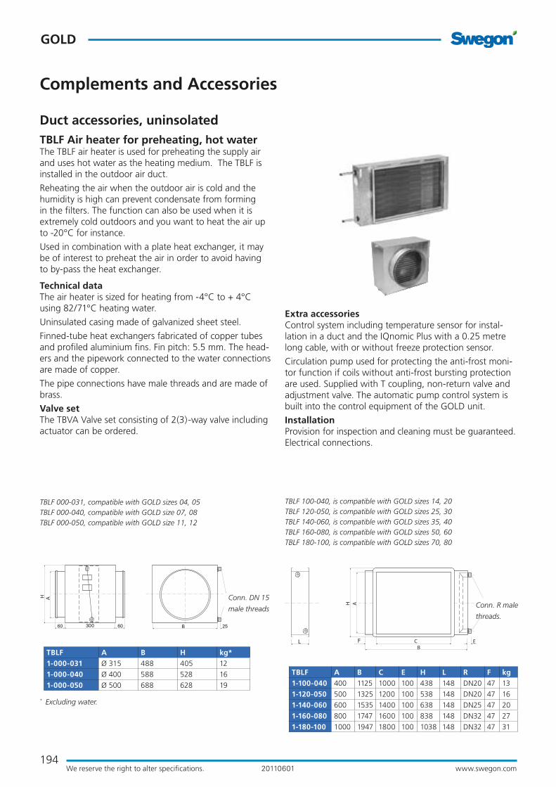
TBLF Air heater for preheating, hot water The TBLF air heater is used for preheating the supply air and uses hot water as the heating medium. The TBLF is installed in the outdoor air duct.
Reheating the air when the outdoor air is cold and the humidity is high can prevent condensate from forming in the filters. The function can also be used when it is extremely cold outdoors and you want to heat the air up to -20°C for instance.
Used in combination with a plate heat exchanger, it may be of interest to preheat the air in order to avoid having to by-pass the heat exchanger.
Technical dataThe air heater is sized for heating from -4°C to + 4°C using 82/71°C heating water.
Uninsulated casing made of galvanized sheet steel.
Finned-tube heat exchangers fabricated of copper tubes and profiled aluminium fins. Fin pitch: 5.5 mm. The head-ers and the pipework connected to the water connections are made of copper.
The pipe connections have male threads and are made of brass.
Valve setThe TBVA Valve set consisting of 2(3)-way valve including actuator can be ordered.
TBLF 000-031, compatible with GOLD sizes 04, 05TBLF 000-040, compatible with GOLD size 07, 08TBLF 000-050, compatible with GOLD size 11, 12
50
H
60 60300
A
B 25
210 C E
H
50 100B
A60
TBLF 100-040, is compatible with GOLD sizes 14, 20TBLF 120-050, is compatible with GOLD sizes 25, 30TBLF 140-060, is compatible with GOLD sizes 35, 40TBLF 160-080, is compatible with GOLD sizes 50, 60TBLF 180-100, is compatible with GOLD sizes 70, 80
TBLF A B C E H L R F kg1-100-040 400 1125 1000 100 438 148 DN20 47 13
1-120-050 500 1325 1200 100 538 148 DN20 47 16
1-140-060 600 1535 1400 100 638 148 DN25 47 20
1-160-080 800 1747 1600 100 838 148 DN32 47 27
1-180-100 1000 1947 1800 100 1038 148 DN32 47 31
Conn. DN 15
male threads
Extra accessoriesControl system including temperature sensor for instal-lation in a duct and the IQnomic Plus with a 0.25 metre long cable, with or without freeze protection sensor.
Circulation pump used for protecting the anti-frost moni-tor function if coils without anti-frost bursting protection are used. Supplied with T coupling, non-return valve and adjustment valve. The automatic pump control system is built into the control equipment of the GOLD unit.
InstallationProvision for inspection and cleaning must be guaranteed.Electrical connections.
Conn. R male
threads.
TBLF A B H kg*1-000-031 Ø 315 488 405 12
1-000-040 Ø 400 588 528 16
1-000-050 Ø 500 688 628 19
* Excluding water.
Duct accessories, uninsolated
195www.swegon.comWe reserve the right to alter specifications.
GOLD
20110601
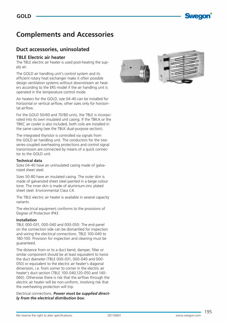
TBLE Electric air heaterThe TBLE electric air heater is used post-heating the sup-ply air.
The GOLD air handling unit’s control system and its efficient rotary heat exchanger make it often possible design ventilation systems without downstream air heat-ers according to the ERS model if the air handling unit is operated in the temperature control mode.
Air heaters for the GOLD, size 04-40 can be installed for horizontal or vertical airflow, other sizes only for horizon-tal airflow.
For the GOLD 50/60 and 70/80 units, the TBLE is incorpo-rated into its own insulated unit casing. If the TBKA or the TBKC air cooler is also included, both coils are installed in the same casing (see the TBLK dual-purpose section).
The integrated thyristor is controlled via signals from the GOLD air handling unit. The conductors for the two series-coupled overheating protections and control signal transmission are connected by means of a quick connec-tor to the GOLD unit.
Technical dataSizes 04-40 have an uninsulated casing made of galva-nized sheet steel.
Sizes 50-80 have an insulated casing. The outer skin is made of galvanized sheet steel painted in a beige colour tone. The inner skin is made of aluminium-zinc plated sheet steel. Environmental Class C4.
The TBLE electric air heater is available in several capacity variants.
The electrical equipment conforms to the provisions of Degree of Protection IP43.
InstallationTBLE 000-031, 000-040 and 000-050: The end panel on the connection side can be dismantled for inspection and wiring the electrical connections. TBLE 100-040 to 180-100: Provision for inspection and cleaning must be guaranteed.
The distance from or to a duct bend, damper, filter or similar component should be at least equivalent to twice the duct diameter (TBLE 000-031, 000-040 and 000-050) or equivalent to the electric air heater’s diagonal dimension, i.e. from corner to corner in the electric air heater’s duct section (TBLE 100-040,120-050 and 140-060). Otherwise there is risk that the airflow through the electric air heater will be non-uniform, involving risk that the overheating protection will trip.
Electrical connections. Power must be supplied direct-ly from the electrical distribution box.
Complements and Accessories
Duct accessories, uninsolated

196
GOLD
www.swegon.comWe reserve the right to alter specifications. 20110601
TBLE 000-031, corresponds to GOLD sizes 04, 05TBLE-000-040, corresponds to GOLD sizes 07, 08
Complements and Accessories
B 1919 L65...70 65...70
H A
200
19TBLE 000-031, corresponds to GOLD sizes 04, 05TBLE-000-040, corresponds to GOLD sizes 07, 08TBLE-000-050, corresponds to GOLD sizes 11, 12
TBLE ø A kg3-000-031-030-x 315 7
3-000-031-045-x 315 8
3-000-031-075-x 315 9
4-000-031-12-1 315 20
4-000-040-06-1 400 9
4-000-040-12-1 400 12
4-000-040-06-2 400 9
A
42 42375
278
71
TBLE ø A B H L kg4-000-031-20-1 315 350 350 600 30
4-000-031-27-1 315 350 350 700 32
4-000-031-12-2 315 350 350 500 23
4-000-031-20-2 315 350 350 700 30
4-000-031-27-2 315 350 350 700 35
4-000-040-20-1 400 400 400 500 29
4-000-040-27-1 400 400 400 600 35
4-000-040-36-1 400 400 400 700 40
4-000-040-47-1 400 400 400 700 47
4-000-040-12-2 400 400 400 500 25
4-000-040-20-2 400 400 400 700 33
4-000-040-27-2 400 400 400 700 38
4-000-040-36-2 400 400 400 800 48
4-000-040-47-2 400 400 400 800 56
4-000-050-08-1 500 500 500 370 24
4-000-050-08-2 500 500 500 500 24
4-000-050-12-1 500 500 500 500 25
4-000-050-12-2 500 500 500 500 27
4-000-050-20-1 500 500 500 500 34
4-000-050-20-2 500 500 500 500 37
4-000-050-27-1 500 500 500 500 37
4-000-050-27-2 500 500 500 500 41
4-000-050-36-1 500 500 500 500 46
4-000-050-36-2 500 500 500 600 54
4-000-050-47-1 500 500 500 600 54
4-000-050-47-2 500 500 500 600 55
4-000-050-69-1 500 500 500 700 69
4-000-050-69-2 500 500 500 700 82
Duct accessories, uninsolated
197www.swegon.comWe reserve the right to alter specifications.
GOLD
20110601
35 35E C
B
H A
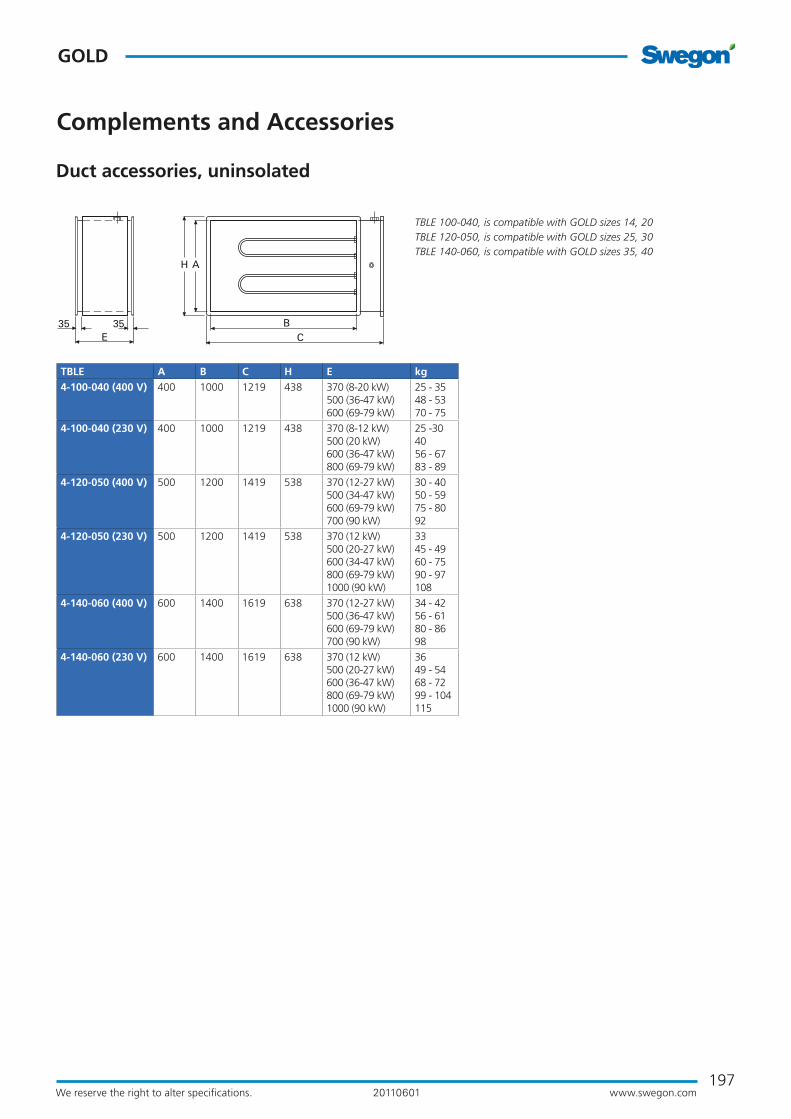
TBLE 100-040, is compatible with GOLD sizes 14, 20TBLE 120-050, is compatible with GOLD sizes 25, 30TBLE 140-060, is compatible with GOLD sizes 35, 40
Complements and Accessories
TBLE A B C H E kg4-100-040 (400 V) 400 1000 1219 438 370 (8-20 kW)
500 (36-47 kW)600 (69-79 kW)
25 - 35 48 - 5370 - 75
4-100-040 (230 V) 400 1000 1219 438 370 (8-12 kW)500 (20 kW) 600 (36-47 kW)800 (69-79 kW)
25 -304056 - 6783 - 89
4-120-050 (400 V) 500 1200 1419 538 370 (12-27 kW) 500 (34-47 kW)600 (69-79 kW)700 (90 kW)
30 - 40 50 - 5975 - 8092
4-120-050 (230 V) 500 1200 1419 538 370 (12 kW) 500 (20-27 kW) 600 (34-47 kW)800 (69-79 kW)1000 (90 kW)
33 45 - 4960 - 7590 - 97108
4-140-060 (400 V) 600 1400 1619 638 370 (12-27 kW) 500 (36-47 kW)600 (69-79 kW)700 (90 kW)
34 - 42 56 - 6180 - 8698
4-140-060 (230 V) 600 1400 1619 638 370 (12 kW) 500 (20-27 kW) 600 (36-47 kW)800 (69-79 kW)1000 (90 kW)
36 49 - 54 68 - 7299 - 104115
Duct accessories, uninsolated
198
GOLD
www.swegon.comWe reserve the right to alter specifications. 20110601
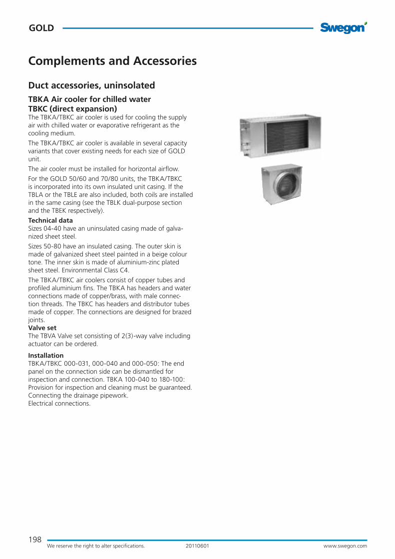
TBKA Air cooler for chilled water TBKC (direct expansion)The TBKA/TBKC air cooler is used for cooling the supply air with chilled water or evaporative refrigerant as the cooling medium.
The TBKA/TBKC air cooler is available in several capacity variants that cover existing needs for each size of GOLD unit.
The air cooler must be installed for horizontal airflow.
For the GOLD 50/60 and 70/80 units, the TBKA/TBKC is incorporated into its own insulated unit casing. If the TBLA or the TBLE are also included, both coils are installed in the same casing (see the TBLK dual-purpose section and the TBEK respectively).
Technical dataSizes 04-40 have an uninsulated casing made of galva-nized sheet steel.
Sizes 50-80 have an insulated casing. The outer skin is made of galvanized sheet steel painted in a beige colour tone. The inner skin is made of aluminium-zinc plated sheet steel. Environmental Class C4.
The TBKA/TBKC air coolers consist of copper tubes and profiled aluminium fins. The TBKA has headers and water connections made of copper/brass, with male connec-tion threads. The TBKC has headers and distributor tubes made of copper. The connections are designed for brazed joints.Valve setThe TBVA Valve set consisting of 2(3)-way valve including actuator can be ordered.
InstallationTBKA/TBKC 000-031, 000-040 and 000-050: The end panel on the connection side can be dismantled for inspection and connection. TBKA 100-040 to 180-100: Provision for inspection and cleaning must be guaranteed.Connecting the drainage pipework.Electrical connections.
Complements and Accessories
Duct accessories, uninsolated

199www.swegon.comWe reserve the right to alter specifications.
GOLD
20110601
50060 60 B
A ø D
B50060 60 E
A
F
ø D
50060 60 B
A ø D
TBKA 000-031, compatible with GOLD size 04/05TBKA 000-040, compatible with GOLD size 07/08TBKA 000-050, compatible with GOLD size 11/12
Drain pipe conn. DN 15 male threads
Outer
diameter
du ext.
Outer
diameter
di ext.
Drain pipe conn. DN 15 male threads
Conn. R male
threads.
* Excl. cooling medium
TBKA A B D R kg* 4-000-031-1 444 490 315 DN15 21
4-000-031-2 444 490 315 DN20 24
TBKC A B D di du kg*3-000-031-1-1 444 490 315 12 18 21
TBKC 000-031, compatible with GOLD size 04/05TBKC 000-040, compatible with GOLD size 07/08TBKC 000-050, compatible with GOLD size 11/12
* Excl. cooling medium
TBKA A B D E F R kg* 4-000-040-1 475 590 400 255 238 DN20 27
4-000-040-2 475 590 400 255 238 DN25 29
4-000-050-1 575 690 500 295 288 DN25 30
4-000-050-2 575 690 500 295 288 DN25 33
4-000-050-5 755 770 500 358 378 DN25 44
4-000-050-6 755 770 500 358 378 DN32 52
Drain pipe conn. DN 15 male threads
Conn. R male
threads.
* Excl. cooling medium
TBKC A B D E F di du kg*3-000-040-1-1 455 590 400 255 228 12 22 28
3-000-050-1-1 575 690 500 295 288 18 22 29
3-000-050-3-1 755 770 500 358 378 22 42 46
* Excl. cooling medium
B50060 60 E
A
F
ø D
Outer
diameter
du ext
Outer
diameter
di ext.
Drain pipe conn. DN 15 male threads
Complements and Accessories
Duct accessories, uninsolated

200
GOLD
www.swegon.comWe reserve the right to alter specifications. 20110601
Drain pipe conn. DN 25 male threads
500 3030
G
E C
B
H A
Drain pipe conn. DN 25 male thread
TBKA 100-040, compatible with GOLD sizes 14, 20TBKA 120-050, compatible with GOLD sizes 25, 30TBKA 140-060, compatible with GOLD sizes 35, 40
TBKC 100-040, compatible with GOLD sizes 14, 20TBKC 120-050, compatible with GOLD sizes 25, 30TBKC 140-060, compatible with GOLD sizes 35, 40
Ext. conn. to be brazed.
* Excl. cooling agent** The connection dimensions of the air cooler are not the same as those of the GOLD unit. Some form of transition piece must be installed between the air handling unit and the air cooler.
* Excl. cooling agent
TBKC A B C E G H di du kg* 3-100-040-1-1 400 1350 1000 175 112,5 650 28 35 81
3-100-040-1-2 400 1350 1000 175 112,5 650 16/22 22/28 84
3-100-040-2-1 400 1350 1000 175 112,5 650 28 35 86
3-100-040-2-2 400 1350 1000 175 112,5 650 16/22 22/28 89
3-120-050-1-1 500 1590 1200 195 170 840 28 35 108
3-120-050-1-2 500 1590 1200 195 170 840 16/28 22/35 112
3-120-050-2-1 500 1590 1200 195 170 840 35 42 116
3-120-050-2-2 500 1590 1200 195 170 840 22/28 28/35 121
3-120-050-3-1 500 1590 1200 195 170 840 35 42 123
3-120-050-3-2 500 1590 1200 195 170 840 22/35 28/42 128
3-140-060-1-1 600 1950 1400 275 175 950 35 42 147
3-140-060-1-2 600 1950 1400 275 175 950 22/28 28/35 152
3-140-060-2-1 600 1950 1400 275 175 950 35 42 156
3-140-060-2-2 600 1950 1400 275 175 950 22/28 28/35 161
3-140-060-3-1 600 1950 1400 275 175 950 42 54 169
3-140-060-3-2 600 1950 1400 275 175 950 28/35 35/42 175
Outer
diameter
du ext
Outer
diameter
di ext.
Complements and Accessories
Conn. R male
threads.
TBKA A B C E G H R kg*5-100-040-1 400 1295 1000 148 113 625 DN32 89
5-100-040-2 400 1295 1000 148 113 625 DN32 94
5-100-040-3 400 1295 1000 148 113 625 DN32 99
5-120-040-4** 400 1495 1200 148 113 625 DN40 113
5-120-050-1 500 1595 1200 198 168 835 DN40 126
5-120-050-2 500 1595 1200 198 168 835 DN50 137
5-120-050-3 500 1595 1200 198 168 835 DN50 146
5-140-050-4** 500 1790 1400 195 168 835 DN50 165
5-140-060-1 600 1885 1400 243 170 940 DN50 160
5-140-060-2 600 1885 1400 243 170 940 DN50 171
5-140-060-3 600 1885 1400 243 170 940 DN65 184
5-160-060-4** 600 2085 1600 243 170 940 DN65 204
Duct accessories, uninsolated

201www.swegon.comWe reserve the right to alter specifications.
GOLD
20110601
Complements and Accessories
Duct accessoriesTBBD Mixing SectionThe TBBD mixing section is available for the GOLD SD in sizes 04-80.
The mixing section can be used when it is desirable use recirculated air for completely or partially heating a buil-ding while it is unoccupied.
The TBBD consists of a spiral tubular T-piece (sizes 05-12) or a rectangular duct with three connections for slip-clamp jointing (sizes 20-80).
The spiral duct joints (sizes 05-12) in required quantity, or sets of slip clamps (sizes 14-80) are included in the supply.
The damper is always supplied with mounted damper actuator. These have modulated action.
The mixing section can be ordered with two or three dampers depending on its range of application. These can be according to Alternative 1 or 2. See the examples on the next page.
Additional equipment required: Supply air units should be provided with a downstream electric air heater or air heater for hot water.
Work to be carried out at the building site: Install the mixing section securing it to the air handling unit/duct Install dampers for the mixing section or duct Wire elec-trical connections to the GOLD unit’s control equipment (separate power supply is not required) Install insulation conforming to local regulations

202
GOLD
www.swegon.comWe reserve the right to alter specifications. 20110601
Complements and Accessories
Duct accessoriesSizes 05, 08 and 12
Example 1, two dampersThe mixing section is supplied with two mounted dam-pers on one spiral tubular T-piece. The connecting rod to the common damper actuator is fitted. The linkage is connected on the right-hand side. The mixing section can easily be converted to enable connection of the linkage on the left-hand side.
Examples 2 and 3, three dampersAs example 1 + one unmounted damper with its own damper motor and one spiral tubular T-piece.
Sizes 20-80
Example 1, two dampersThe mixing section consists of two unmounted dampers and one rectangular duct with three connections for slip-clamp jointing. The connecting rod for the common dam-per motor is supplied with the unit section for size 20-30 air handling units. The dampers of the size 40-80 unit sections each have their own damper motor. The mixing section can be installed for connection on the right-hand or left-hand side.
Example 3, three dampers, alternative 2. As example 1 + one unmounted damper with its own damper motor and one rectangular duct with three con-nections for slip-clamp jointing.
Normal operation
Mixing
Normal operation
Mixing
Normal operation
Mixing
Example 1 (two dampers)
Example 2 (three dampers, alternative 1)
Storlek 05-08
Example 3 (three dampers, alternative 2)
The items supplied from
Swegon are shaded in grey.
Outdoor air Extract air
Exhaust air
Supply air
203www.swegon.comWe reserve the right to alter specifications.
GOLD
20110601
Complements and Accessories
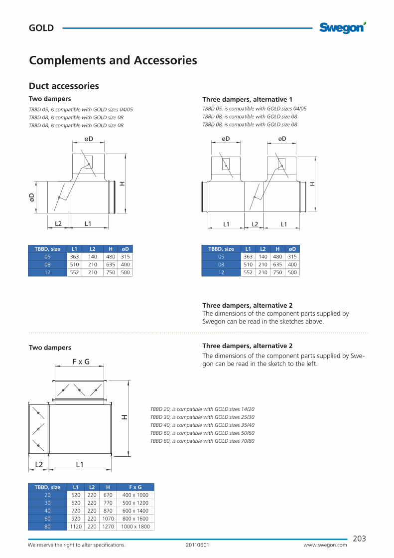
Duct accessoriesThree dampers, alternative 1
Three dampers, alternative 2 The dimensions of the component parts supplied by Swegon can be read in the sketches above.
TBBD 05, is compatible with GOLD sizes 04/05
TBBD 08, is compatible with GOLD size 08
TBBD 08, is compatible with GOLD size 08
Two dampers Three dampers, alternative 2
The dimensions of the component parts supplied by Swe-gon can be read in the sketch to the left.
TBBD 05, is compatible with GOLD sizes 04/05
TBBD 08, is compatible with GOLD size 08
TBBD 08, is compatible with GOLD size 08
Two dampers
TBBD 20, is compatible with GOLD sizes 14/20
TBBD 30, is compatible with GOLD sizes 25/30
TBBD 40, is compatible with GOLD sizes 35/40
TBBD 60, is compatible with GOLD sizes 50/60
TBBD 80, is compatible with GOLD sizes 70/80
øD
øD
L2 L1
H
L1 L1L2
øD øD
H
TBBD, size L1 L2 H øD05 363 140 480 315
08 510 210 635 400
12 552 210 750 500
TBBD, size L1 L2 H øD05 363 140 480 315
08 510 210 635 400
12 552 210 750 500
L1L2
F x G
H
TBBD, size L1 L2 H F x G20 520 220 670 400 x 1000
30 620 220 770 500 x 1200
40 720 220 870 600 x 1400
60 920 220 1070 800 x 1600
80 1120 220 1270 1000 x 1800

204
GOLD
www.swegon.comWe reserve the right to alter specifications. 20110601
Complements and Accessories
TBFA PrefilterThe prefilter should be installed in the outdoor air duct and/or the extract air duct.
The prefilter is used in ventilation systems in which the extract air and/or the outdoor air is heavily polluted and it is desirable to prevent the fine filter located in the GOLD unit from becoming clogged after a short period of use.
Technical dataThe TBFA has an uninsulated casing made of galvanized sheet steel. Insulated Inspection door.
Filter of type woven aluminium filter or class G3 compact filter.
Extra accessoriesThe pressure sensor can be selected; alarm limit and current filter pressure can then be read in the hand-held micro terminal of the GOLD unit.
InstallationProvision for inspection and cleaning must be guaranteed.Install insulation conforming to local regulations.
TBFA 000-031, is compatible with GOLD sizes 04, 05TBFA 000-040, is compatible with GOLD size 07, 08TBFA 000-050, is compatible with GOLD size 11, 12
TBFA 100-040, is compatible with GOLD sizes 14, 20TBFA 120-050, is compatible with GOLD sizes 25, 30TBFA 140-060, is compatible with GOLD sizes 35, 40TBFA 160-080, is compatible with GOLD sizes 50, 60TBFA 180-100, is compatible with GOLD sizes 70, 80TBFA 240-120, is compatible with GOLD sizes 70, 80
Outdoor air
Extract air
Supply air
Exhaust air
TBFA A B C H kg100-040 400 1200 1000 600 26
120-050 500 1500 1200 600 36
140-060 600 1800 1400 900 48
160-080 800 2475 1600 1000 59
180-100 1000 2400 1800 1200 68
240-120 1200 3000 2400 1800 140
TBFA B D H kg000-031 500 315 500 18
000-040 600 400 600 22
000-050 900 500 600 24
Duct accessories, uninsolated
B 40
C 320
380
HA
50
50
ø D
B 40
320
380
H
50
50
205www.swegon.comWe reserve the right to alter specifications.
GOLD
20110601
Complements and Accessories
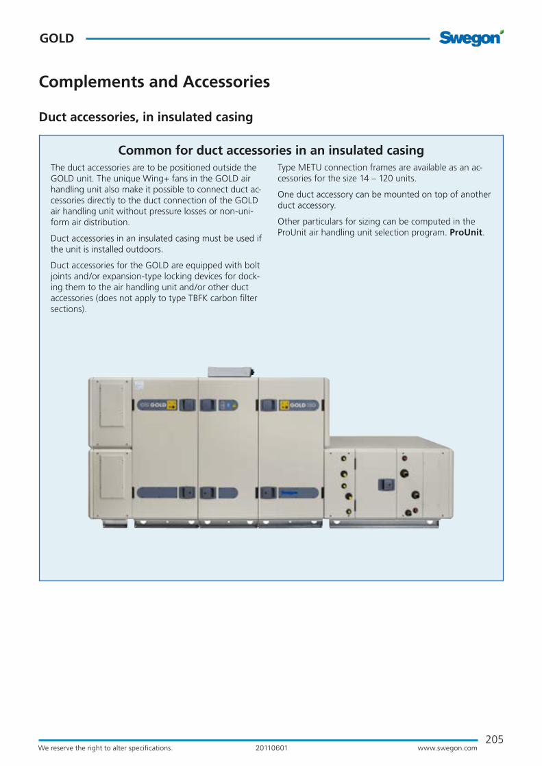
Common for duct accessories in an insulated casingThe duct accessories are to be positioned outside the GOLD unit. The unique Wing+ fans in the GOLD air handling unit also make it possible to connect duct ac-cessories directly to the duct connection of the GOLD air handling unit without pressure losses or non-uni-form air distribution.
Duct accessories in an insulated casing must be used if the unit is installed outdoors.
Duct accessories for the GOLD are equipped with bolt joints and/or expansion-type locking devices for dock-ing them to the air handling unit and/or other duct accessories (does not apply to type TBFK carbon filter sections).
Type METU connection frames are available as an ac-cessories for the size 14 – 120 units.
One duct accessory can be mounted on top of another duct accessory.
Other particulars for sizing can be computed in the ProUnit air handling unit selection program. ProUnit.
Duct accessories, in insulated casing

206
GOLD
www.swegon.comWe reserve the right to alter specifi cations. 20110601
TCSA Damper section TCSA dampers are used as shut-off dampers or forced airfl ow dampers. Sizes 12 - 120 can also be used for other applications, such as outdoor air dampers for the ReCO2
control function.
Shut-off dampers are normally used if the air handling unit is idle during some period, for example at night, or if an air heater for hot water without anti-frost burst protec-tion is used.
To be installed for horizontal airfl ow.
Complete with damper actuator for 230 or 24 V. The actuator can be selected with spring return or on/off actuation. TCSA sizes 12 - 120 are also available with modulating type actuator with spring return.
Technical dataInsulated casing. The outer skin is made of galvanized sheet steel painted in a beige colour tone (NCS S2005-Y30R). The inner skin is made of aluminium-zinc plated sheet steel. Environmental class C4.Tightness class 3 to EN 1751.The dampers are journalled in nylon bushings.
InstallationThe damper section should be mounted directly against the air handling unit or insulated duct accessory. Wire the control and power supply cables to the appropri-ate wiring terminal on the air handling unit.
Complements and Accessories
Duct accessories, in insulated casing

207www.swegon.comWe reserve the right to alter specifications.
GOLD
20110601
BL52*
H
100
16
60 60
BL
16
60 60
52*
H
100
Connection dimensions to duct:TCSA 12 ø 500
TCSA B H L kgEnd connection panel, if required
kg1-12 1199 648 353 52 13
The base frame is always supplied in assembled condition. If the duct accessory is fitted to the upper ductwork, above the duct accessory fitted to the lower ductwork, remove the base beams to the extent necessary, at the building site.* If several duct accessories are arranged in succession, the end connection panel is supplied only on the duct acces-sory farthest out facing the ductwork.
Connection dimensions to duct:TCSA 05 ø 315 TCSA 08 ø 400
TCSA B H L kgEnd connection panel, if required
kg1-05 825 460 353 33 7
1-08 995 542 353 38 10
Base beams are optional. * If several duct accessories are arranged in succession, the end connection panel is supplied only on the duct accessory farthest out facing the ductwork.
Complements and Accessories
Duct accessories, in insulated casing
BL
21
52*
H
10060 60
Connection dimensions to duct:TCSA 20 1000 x 400 mmTCSA 30 1200 x 500 mmTCSA 40 1400 x 600 mm
The base frame is always supplied in assembled condition. If the duct accessory is fitted to the upper ductwork, above the duct accessory fitted to the lower ductwork, remove the base beams to the extent necessary, at the building site.* If several duct accessories are arranged in succession, the end connection panel is supplied only on the duct accessory farthest out facing the ductwork.
TCSA B H L kgEnd connection panel, if required
kg1-20 1400 7761)/6202) 353 661)/612) 191)/152)
1-30 1600 9061)/6902) 353 741)/662) 231)/172)
1-40 1990 10801)/9062) 353 921)/862) 311)/262)
208
GOLD
www.swegon.comWe reserve the right to alter specifications. 20110601
Complements and Accessories
Duct accessories, in insulated casing
A* L 24** B
21
H
100
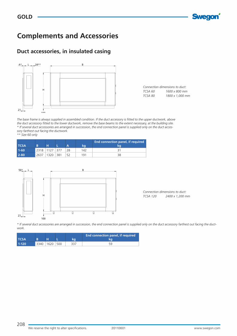
Connection dimensions to duct:TCSA 60 1600 x 800 mmTCSA 80 1800 x 1,000 mm
The base frame is always supplied in assembled condition. If the duct accessory is fitted to the upper ductwork, above the duct accessory fitted to the lower ductwork, remove the base beams to the extent necessary, at the building site.* If several duct accessories are arranged in succession, the end connection panel is supplied only on the duct acces-sory farthest out facing the ductwork. ** Size 60 only
TCSA B H L A kgEnd connection panel, if required
kg1-60 2318 1127 377 28 142 31
2-80 2637 1320 381 52 191 38
56* L B
21
H
100
Connection dimensions to duct:TCSA 120 2400 x 1,200 mm
* If several duct accessories are arranged in succession, the end connection panel is supplied only on the duct accessory farthest out facing the duct-work.
TCSA B H L kgEnd connection panel, if required
kg1-120 3340 1620 500 337 59

209www.swegon.comWe reserve the right to alter specifications.
GOLD
20110601
BL52*
H
100
16
60 60
Complements and Accessories
Spacer section, TCGA/ Inspection section, TCIA.The TCGA spacer section/TCIA inspection section is used when provision for spacing or inspection is required.
The TCIA inspection section is available in two variants, with inspection door the entire length of the section (sizes 05-120), or split cover panel/inspection door (sizes 05-40).The spacer section/inspection section must be installed for horizontal airflow.
Technical dataInsulated casing. The outer skin is made of galvanized sheet steel, prepainted in a beige colour tone(NCS S2005-Y30R). The inner skin is made of aluminium-zinc plated sheet steel. Environmental Class C4.
InstallationThe spacer section/inspection section should be fitted directly to the air handling unit or other insulated duct accessory.
Provision for inspection and cleaning the spacer section must be guaranteed. The cover panel is easy to remove.
Duct accessories, in insulated casing
Connection dimensions to duct:TCGA 12 ø 500
TCGA B H L kgEnd connection panel, if required
kg2-12 1199 648 723 61 13
The base frame is always supplied in assembled condition. If the duct accessory is fitted to the upper ductwork, above the duct accessory fitted to the lower ductwork, remove the base beams to the extent necessary, at the building site.* If several duct accessories are arranged in succession, the end connection panel is supplied only on the duct accessory farthest out facing the ductwork.
Connection dimensions to duct:TCGA 05 ø 315 TCGA 08 ø 400
TCGA B H L kgEnd connection panel, if required
kg2-05 825 460 723 38 7
2-08 995 542 723 46 10
Base beams are optional. * If several duct accessories are arranged in succession, the end connection panel is supplied only on the duct accessory farthest out facing the ductwork.
BL
16
52*
H
10060 60
Spacer Section, TCGA
Spacer Section, TCGA
TCIA inspection section. Inspection door the entire length of the section.
TCIA inspection section. Split cover panel/inspection door.

210
GOLD
www.swegon.comWe reserve the right to alter specifications. 20110601
Complements and Accessories
Duct accessories, in insulated casing
21
B
H
100
LA* 24**
Connection dimensions to duct:TCGA 60 1600 x 800 mmTCGA 80 1800 x 1000 mm
The base frame is always supplied in assembled condition. If the duct accessory is fitted to the upper ductwork, above the duct accessory fitted to the lower ductwork, remove the base beams to the extent necessary, at the building site.* If several duct accessories are arranged in succession, the end connection panel is supplied only on the duct accessory farthest out facing the ductwork.** Size 60 only
TCGA B H L A kgEnd connection panel, if required
kg1-60 2318 1127 617 28 118 31
2-80 2637 1320 617 52 139 38
BL
21
52*
H
10060 60
Connection dimensions to duct:TCGA 20 1000 x 400 mmTCGA 30 1200 x 500 mmTCGA 40 1400 x 600 mm
The base frame is always supplied in assembled condition. If the duct accessory is fitted to the upper ductwork, above the duct accessory fitted to the lower ductwork, remove the base beams to the extent necessary, at the building site.* If several duct accessories are arranged in succession, the end connection panel is supplied only on the duct accessory farthest out facing the ductwork.
TCGA B H L kgEnd connection panel, if required
kg2-20 1400 7761)/6202) 723 711)/662) 191)/152)
2-30 1600 9061)/6902) 723 791)/742) 231)/172)
2-40 1990 10801)/9062) 723 961)/912) 311)/262)
56* L B
21
H
100
Connection dimensions to duct:TCGA 120 2400 x 1200 mm
* If several duct accessories are arranged in succession, the end connection panel is supplied only on the duct accessory farthest out facing the ductwork.
TCGA B H L kgEnd connection panel, if required
kg1-120 3340 1620 720 243 59
1) When mounting on outlet.2) When mounting on inlet.
Spacer Section, TCGA

211www.swegon.comWe reserve the right to alter specifications.
GOLD
20110601
BL52*
H
100
16
60 60
Complements and Accessories
Duct accessories, in insulated casing
Connection dimensions to duct:TCIA 12 ø 500
TCIA B H L kgEnd connection panel, if required
kg1-12 1199 648 723 62 13
The base frame is always supplied in assembled condition. If the duct accessory is fitted to the upper ductwork, above the duct accessory fitted to the lower ductwork, remove the base beams to the extent necessary, at the building site.* If several duct accessories are arranged in succession, the end connection panel is supplied only on the duct accessory farthest out facing the ductwork.
Connection dimensions to duct:TCIA 05 ø 315 TCIA 08 ø 400
TCIA B H L kgEnd connection panel, if required
kg1-05 825 460 723 40 7
1-08 995 542 723 47 10
Base beams are optional. * If several duct accessories are arranged in succession, the end connection panel is supplied only on the duct accessory farthest out facing the ductwork.
BL
16
52*
H
10060 60
BL
21
52*
H
10060 60
Connection dimensions to duct:TCIA 20 1000 x 400 mmTCIA 30 1200 x 500 mmTCIA 40 1400 x 600 mm
The base frame is always supplied in assembled condition. If the duct accessory is fitted to the upper ductwork, above the duct accessory fitted to the lower ductwork, remove the base beams to the extent necessary, at the building site.* If several duct accessories are arranged in succession, the end connection panel is supplied only on the duct accessory farthest out facing the ductwork.
TCIA B H L kgEnd connection panel, if required
kg1-20 1400 7761)/6202) 723 741)/672) 191)/152)
1-30 1600 9061)/6902) 723 821)/752) 231)/172)
1-40 1990 10801)/9062) 723 981)/932) 311)/262)
1) When mounting on outlet.2) When mounting on inlet.
The TCIA inspection section, inspection door in the entire length of the section.

212
GOLD
www.swegon.comWe reserve the right to alter specifications. 20110601
21
B
H
100
LA* 24**
Connection dimensions to duct:TCIA 60 1600 x 800 mmTCIA 80 1800 x 1000 mm
The base frame is always supplied in assembled condition. If the duct accessory is fitted to the upper ductwork, above the duct accessory fitted to the lower ductwork, remove the base beams to the extent necessary, at the building site.* If several duct accessories are arranged in succession, the end connection panel is supplied only on the duct accessory farthest out facing the ductwork.** Size 60 only
TCIA B H L A kgEnd connection panel, if required
kg1-60 2318 1127 542 28 114 31
1-80 2637 1320 542 52 136 38
56* L B
21
H
100
Connection dimensions to duct:TCIA 120 2400 x 1200 mm
* If several duct accessories are arranged in succession, the end connection panel is supplied only on the duct accessory farthest out facing the ductwork.
TCIA B H Lkg
End connection panel, if required
kg1-120 3340 1620 500 211 59
Complements and Accessories
Duct accessories, in insulated casing
The TCIA inspection section, inspection door in the entire length of the section.

213www.swegon.comWe reserve the right to alter specifications.
GOLD
20110601
BL52*
H
256
100
16
60 60
Complements and Accessories
Duct accessories, in insulated casing
Connection dimensions to duct:TCIA 12 ø 500
TCIA B H L kgEnd connection panel, if required
kg1-12 1199 648 723 62 13
The base frame is always supplied in assembled condition. If the duct accessory is fitted to the upper ductwork, above the duct accessory fitted to the lower ductwork, remove the base beams to the extent necessary, at the building site.* If several duct accessories are arranged in succession, the end connection panel is supplied only on the duct accessory farthest out facing the ductwork.
Connection dimensions to duct:TCIA 05 ø 315 TCIA 08 ø 400
TCIA B H L kgEnd connection panel, if required
kg1-05 825 460 723 40 7
1-08 995 542 723 47 10
Base beams are optional. * If several duct accessories are arranged in succession, the end connection panel is supplied only on the duct accessory farthest out facing the ductwork.
BL
16
52*
H
10060 60
256
BL
21
52*
H
10060 60
256
Connection dimensions to duct:TCIA 20 1000 x 400 mmTCIA 30 1200 x 500 mmTCIA 40 1400 x 600 mm
The base frame is always supplied in assembled condition. If the duct accessory is fitted to the upper ductwork, above the duct accessory fitted to the lower ductwork, remove the base beams to the extent necessary, at the building site.* If several duct accessories are arranged in succession, the end connection panel is supplied only on the duct acces-sory farthest out facing the ductwork.
TCIA B H L kgEnd connection panel, if required
kg1-20 1400 7761)/6202) 723 741)/672) 191)/152)
1-30 1600 9061)/6902) 723 821)/752) 231)/172)
1-40 1990 10801)/9062) 723 981)/932) 311)/262)
1) When mounting on outlet.2) When mounting on inlet.
TCIA inspection section, split cover panel/inspection door

214
GOLD
www.swegon.comWe reserve the right to alter specifi cations. 20110601
Complements and Accessories
TCDA Unit sound attenuatorThe TCDA sound attenuator is a rectangular sound at-tenuator designed for mounting directly against the air handling unit.
To be installed for horizontal airfl ow.
Technical dataInsulated casing. The outer skin is made of galvanized sheet steel painted in a beige colour tone (NCS S2005-Y30R). The inner skin is made of aluminium-zinc plated sheet steel. Environmental class C4.Sound absorption material of type Cleanolon-AL. Cleano-lon-AL consists of mineral wool covered with perforated aluminium foil. Type approved with regard to suitability for cleaning, emissions and fi bre entrainment. The mate-rial conforms to the provisions of Surface Layer Class 1 (the highest class).
InstallationThe sound attenuator should be mounted directly against the air handling unit or insulated duct accessory. Provision for inspection and cleaning must be guaranteed.
Duct accessories, in insulated casing
BL
16
52*
H
Connection dimensions to duct:TCDA 12 ø 500
TCDA B H L kgEnd connection panel, if required
kg1-12 1199 648 948 97 13
The base frame is always supplied in assembled condition. If the duct accessory is fi tted to the upper ductwork, above the duct accessory fi tted to the lower ductwork, remove the base beams to the extent necessary, at the building site.* If several duct accessories are arranged in succession, the end connection panel is supplied only on the duct acces-sory farthest out facing the ductwork.
Connection dimensions to duct:TCDA 05 ø 315 TCDA 08 ø 400
TCDA B H L kgEnd connection panel, if required
kg1-05 825 460 948 63 7
1-08 995 542 948 74 10
Base beams are optional.* If several duct accessories are arranged in succession, the end connection panel is supplied only on the duct accessory farthest out facing the ductwork.
B
16
52*
H
100
L
60 60
BL52*
H
100
16
60 60

215www.swegon.comWe reserve the right to alter specifications.
GOLD
20110601
Complements and Accessories
Duct accessories, in insulated casing
21
B
H
100
LA* 24**
Connection dimensions to duct:TCDA 60 1600 x 800 mmTCDA 80 1800 x 1,000 mm
The base frame is always supplied in assembled condition. If the duct accessory is fitted to the upper ductwork, above the duct accessory fitted to the lower ductwork, remove the base beams to the extent necessary, at the building site. * If several duct accessories are arranged in succession, the end connection panel is supplied only on the duct accessory farthest out facing the ductwork. ** Size 60 only
TCDA B H L A kgEnd connection panel, if required
kg1-60 2318 1127 972 28 245 31
2-80 2637 1320 972 52 288 38
BL
21
52*
H
10060 60
Connection dimensions to duct:TCDA 20 1000 x 400 mmTCDA 30 1200 x 500 mmTCDA 40 1400 x 600 mm
The base frame is always supplied in assembled condition. If the duct accessory is fitted to the upper ductwork, above the duct accessory fitted to the lower ductwork, remove the base beams to the extent necessary, at the building site. * If several duct accessories are arranged in succession, the end connection panel is supplied only on the duct accessory farthest out facing the ductwork.
TCDA B H L kgEnd connection panel, if required
kg1-20 1400 7761)/6202) 948 1201)/1062) 191)/152)
1-30 1600 9061)/6902) 948 1431)/1242) 231)/172)
1-40 1990 10801)/9062) 948 1871)/1682) 311)/262)
1) When mounting on outlet.2) When mounting on inlet.
Connection dimensions to duct:TCDA 120 2400 x 1,200 mm
* If several duct accessories are arranged in succession, the end connection panel is supplied only on the duct accessory farthest out facing the ductwork.
TCDA B H Lkg
End connection panel, if required
kg1-120 3340 1620 1070 443 59
56* L B
21
H
100
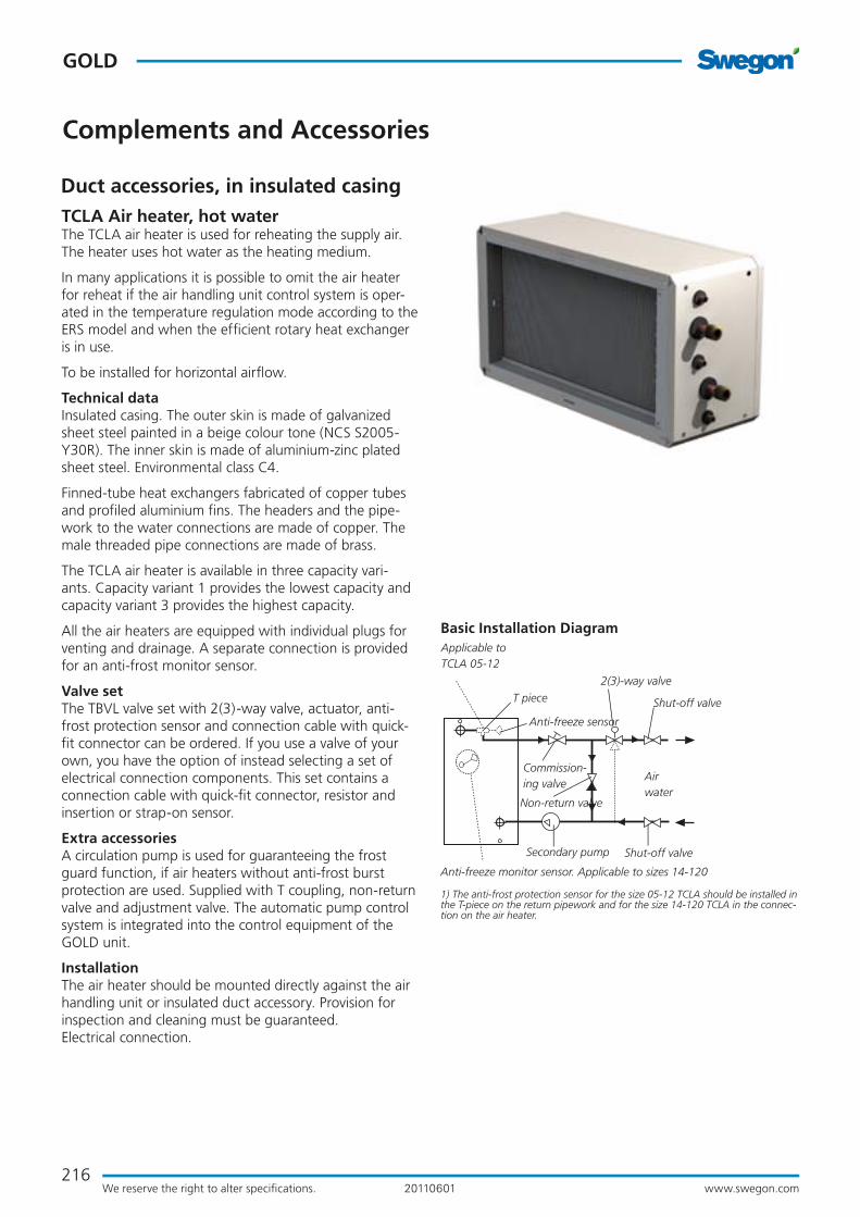
216
GOLD
www.swegon.comWe reserve the right to alter specifi cations. 20110601
Complements and Accessories
TCLA Air heater, hot waterThe TCLA air heater is used for reheating the supply air. The heater uses hot water as the heating medium.
In many applications it is possible to omit the air heater for reheat if the air handling unit control system is oper-ated in the temperature regulation mode according to the ERS model and when the effi cient rotary heat exchanger is in use.
To be installed for horizontal airfl ow.
Technical dataInsulated casing. The outer skin is made of galvanized sheet steel painted in a beige colour tone (NCS S2005-Y30R). The inner skin is made of aluminium-zinc plated sheet steel. Environmental class C4.
Finned-tube heat exchangers fabricated of copper tubes and profi led aluminium fi ns. The headers and the pipe-work to the water connections are made of copper. The male threaded pipe connections are made of brass.
The TCLA air heater is available in three capacity vari-ants. Capacity variant 1 provides the lowest capacity and capacity variant 3 provides the highest capacity.
All the air heaters are equipped with individual plugs for venting and drainage. A separate connection is provided for an anti-frost monitor sensor.
Valve set The TBVL valve set with 2(3)-way valve, actuator, anti-frost protection sensor and connection cable with quick-fi t connector can be ordered. If you use a valve of your own, you have the option of instead selecting a set of electrical connection components. This set contains a connection cable with quick-fi t connector, resistor and insertion or strap-on sensor.
Extra accessoriesA circulation pump is used for guaranteeing the frost guard function, if air heaters without anti-frost burst protection are used. Supplied with T coupling, non-return valve and adjustment valve. The automatic pump control system is integrated into the control equipment of the GOLD unit.
InstallationThe air heater should be mounted directly against the air handling unit or insulated duct accessory. Provision for inspection and cleaning must be guaranteed.Electrical connection.
Basic Installation Diagram
T piece
Anti-freeze sensor
Shut-off valve
Airwater
Shut-off valve
2(3)-way valve
Commission-ing valve
Non-return valve
Applicable to TCLA 05-12
Anti-freeze monitor sensor. Applicable to sizes 14-120
Secondary pump
1) The anti-frost protection sensor for the size 05-12 TCLA should be installed in the T-piece on the return pipework and for the size 14-120 TCLA in the connec-tion on the air heater.
Duct accessories, in insulated casing

217www.swegon.comWe reserve the right to alter specifications.
GOLD
20110601
B 84L52*
H
100
16
60 60
B 84L
16
52*
H
10060 60
Complements and Accessories
Duct accessories, in insulated casing
Conn. R male threads.
Conn. DN 8
Connection dimensions to duct:TCLA 12 ø 500
TCLA B H LCapacity variant 1 Capacity variant 2 Capacity variant 3 End connection panel, if required
kgR kg1) R kg1) R kg1)
1-12 1199 648 428 DN20 49 DN20 52 DN25 56 13
1) Not filled with water.
The base frame is always supplied in assembled condition. If the duct accessory is fitted to the upper ductwork, above the duct accessory fitted to the lower ductwork, remove the base beams to the extent necessary, at the building site.* If several duct accessories are arranged in succession, the end connection panel is supplied only on the duct accessory farthest out facing the ductwork.
Conn. R male threads.
Conn. DN 8Connection dimensions to duct:TCLA 05 ø 315 TCLA 08 ø 400
TCLA B H LCapacity variant 1 Capacity variant 2 Capacity variant 3 End connection panel, if required
kgR kg1) R kg1) R kg1)
1-05 825 460 353 DN15 25 DN15 26 DN20 27 7
1-08 995 542 353 DN15 31 DN20 32 DN20 34 10
1) Not filled with water.
Base beams are optional. * If several duct accessories are arranged in succession, the end connection panel is supplied only on the duct accessory farthest out facing the ductwork.
BL
21
52*
H
100
84
60 60
Connection dimensions to duct:TCLA 20 1000 x 400 mmTCLA 30 1200 x 500 mmTCLA 40 1400 x 600 mm
TCLA B H LCapacity variant 1 Capacity variant 2 Capacity variant 3 End connection panel, if required
kgR kg1) R kg1) R kg1)
1-20 1400 776 353 DN20 51 DN25 57 DN25 62 19
1-30 1600 906 353 DN25 61 DN32 69 DN32 77 23
1-40 1990 1080 428 DN32 87 DN40 99 DN40 113 31
1) Not filled with water.
The base frame is always supplied in assembled condition. If the duct accessory is fitted to the upper ductwork, above the duct accessory fitted to the lower ductwork, remove the base beams to the extent necessary, at the building site.* If several duct accessories are arranged in succession, the end connection panel is supplied only on the duct accessory farthest out facing the ductwork.
Conn. R male threads.
Conn. DN 8

218
GOLD
www.swegon.comWe reserve the right to alter specifications. 20110601
21
B 95
H
100
LA* 24**
TCLA B H L ACapacity variant 1 Capacity variant 2 Capacity variant 3 End connection panel, if required
kgR kg1) kg2) R kg1) kg2) R kg1) kg2)
1-60 2318 1127 542 28 DN25 149 111 DN32 160 111 DN50 174 111 31
2-80 2637 1320 542 52 DN25 184 135 DN40 200 135 DN50 220 135 38
Conn. R male threads.
Conn. DN 8
Connection dimensions to duct:TCLA 60 1600 x 800 mmTCLA 80 1800 x 1,000 mm
1) Including casing, not filled with water.2) Casing only.
The base frame is always supplied in assembled condition. If the duct accessory is fitted to the upper ductwork, above the duct accessory fitted to the lower ductwork, remove the base beams to the extent necessary, at the building site.* If several duct accessories are arranged in succession, the end connection panel is supplied only on the duct accessory farthest out facing the ductwork. ** Size 60 only
Complements and Accessories
Duct accessories, in insulated casing
9556* L B
21
H
100
TCLA B H LCapacity variant 1 Capacity variant 2 Capacity variant 3 End connection panel, if required
kgR kg1) kg2) R kg1) kg2) R kg1) kg2)
1-120 3340 1620 720 DN50 339 256 DN65 384 256 DN65 429 256 59
Conn. R male threads.
Conn. DN 8
Connection dimensions to duct:TCLA 120 2400 x 1,200 mm
1) Including casing, not filled with water.2) Casing only.
* If several duct accessories are arranged in succession, the end connection panel is supplied only on the duct accessory farthest out facing the ductwork.
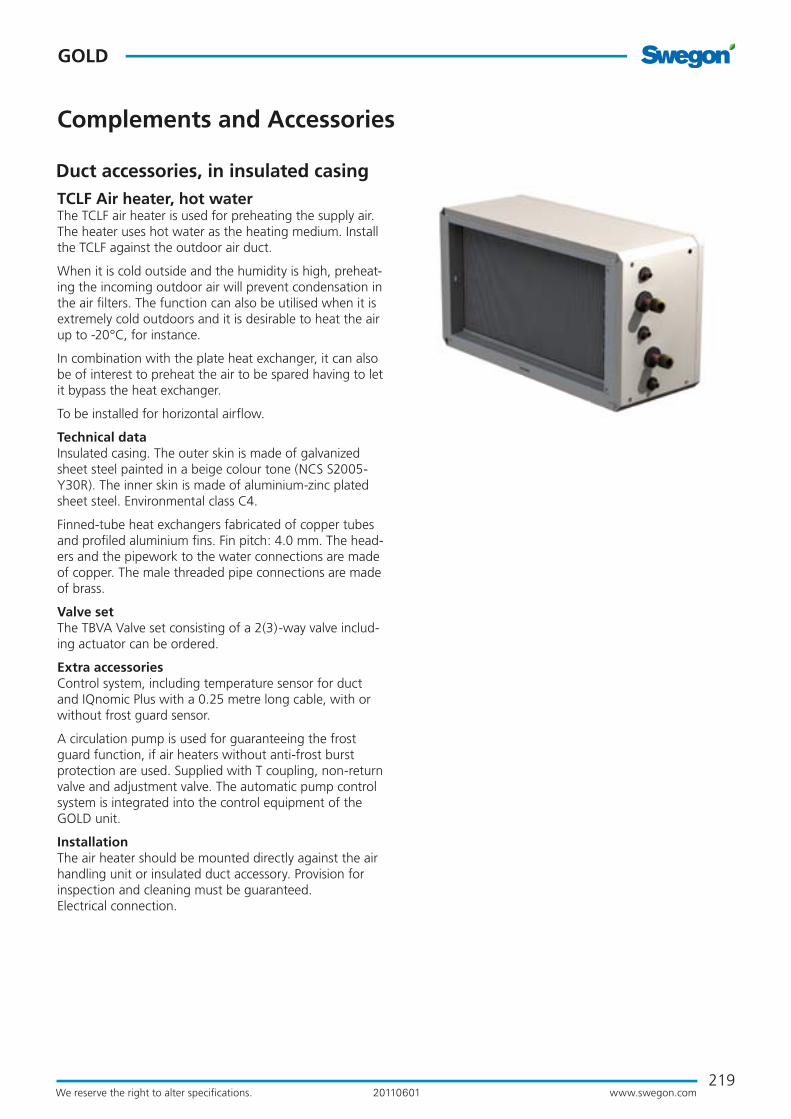
219www.swegon.comWe reserve the right to alter specifi cations.
GOLD
20110601
Complements and Accessories
TCLF Air heater, hot waterThe TCLF air heater is used for preheating the supply air. The heater uses hot water as the heating medium. Install the TCLF against the outdoor air duct.
When it is cold outside and the humidity is high, preheat-ing the incoming outdoor air will prevent condensation in the air fi lters. The function can also be utilised when it is extremely cold outdoors and it is desirable to heat the air up to -20°C, for instance.
In combination with the plate heat exchanger, it can also be of interest to preheat the air to be spared having to let it bypass the heat exchanger.
To be installed for horizontal airfl ow.
Technical dataInsulated casing. The outer skin is made of galvanized sheet steel painted in a beige colour tone (NCS S2005-Y30R). The inner skin is made of aluminium-zinc plated sheet steel. Environmental class C4.
Finned-tube heat exchangers fabricated of copper tubes and profi led aluminium fi ns. Fin pitch: 4.0 mm. The head-ers and the pipework to the water connections are made of copper. The male threaded pipe connections are made of brass.
Valve set The TBVA Valve set consisting of a 2(3)-way valve includ-ing actuator can be ordered.
Extra accessoriesControl system, including temperature sensor for duct and IQnomic Plus with a 0.25 metre long cable, with or without frost guard sensor.
A circulation pump is used for guaranteeing the frost guard function, if air heaters without anti-frost burst protection are used. Supplied with T coupling, non-return valve and adjustment valve. The automatic pump control system is integrated into the control equipment of the GOLD unit.
InstallationThe air heater should be mounted directly against the air handling unit or insulated duct accessory. Provision for inspection and cleaning must be guaranteed.Electrical connection.
Duct accessories, in insulated casing

220
GOLD
www.swegon.comWe reserve the right to alter specifications. 20110601
B 84L52*
H
100
16
60 60
B 84L
16
52*
H
10060 60
Conn. R male threads.
Conn. DN 8
Connection dimensions to duct:TCLF 12 ø 500
1) Not filled with water.
The base frame is always supplied in assembled condition. If the duct accessory is fitted to the upper ductwork, above the duct accessory fitted to the lower ductwork, remove the base beams to the extent necessary, at the building site.* If several duct accessories are arranged in succession, the end connection panel is supplied only on the duct accessory farthest out facing the ductwork.
Conn. R male threads.
Conn. DN 8Connection dimensions to duct:TCLF 05 ø 315 TCLF 08 ø 400
TCLF B H L R kg1)
End connection panel, if requiredkg
1-05 825 460 353 DN15 24 7
1-08 995 542 353 DN15 30 10
1) Not filled with water.
Base beams are optional. * If several duct accessories are arranged in succession, the end connection panel is supplied only on the duct accessory farthest out facing the ductwork.
Complements and Accessories
Duct accessories, in insulated casing
TCLF B H L R kg1)
End connection panel, if requiredkg
1-12 1199 648 428 DN20 48 13
BL
21
52*
H
100
84
60 60
Connection dimensions to duct:TCLF 20 1000 x 400 mmTCLF 30 1200 x 500 mmTCLF 40 1400 x 600 mm
1) Not filled with water.
The base frame is always supplied in assembled condition. If the duct accessory is fitted to the upper ductwork, above the duct accessory fitted to the lower ductwork, remove the base beams to the extent necessary, at the building site.* If several duct accessories are arranged in succession, the end connection panel is supplied only on the duct accessory farthest out facing the ductwork.
Conn. R male threads.
Conn. DN 8
TCLF B H L R kg1)
End connection panel, if requiredkg
1-20 1400 620 353 DN20 46 15
1-30 1600 690 353 DN20 53 17
1-40 1990 906 353 DN25 73 26

221www.swegon.comWe reserve the right to alter specifi cations.
GOLD
20110601
Complements and Accessories
TCLE Electric air heaterThe TCLE electric air heater is used for reheating the supply air.
In many applications it is possible to omit the air heater for reheat if the air handling unit control system is oper-ated in the temperature regulation mode according to the ERS model and when the effi cient rotary heat exchanger is in use.
To be installed for horizontal airfl ow.
The integrated thyristor is controlled via signals from the GOLD air handling unit. The conductors for the two series-coupled overheating protections and control signal transmission are connected by means of a quick connec-tor to the GOLD unit.
Technical dataInsulated casing. The outer skin is made of galvanized sheet steel painted in a beige colour tone (NCS S2005-Y30R). The inner skin is made of aluminium-zinc plated sheet steel. Environmental class C4.
The TCLE air heater is available in several capacity variants.
The electrical equipment conforms to the provisions of Degree of Protection IP43.
InstallationThe air heater should be mounted directly against the air handling unit or insulated duct accessory. The space necessary for obtaining a uniform air stream is provided inside the TCLE. Therefore other duct accessories can be fi tted downstream of the TCLE without risk of overheat-ing.Electrical connection. Power must be supplied directly from the electrical distribution box.
Duct accessories, in insulated casing
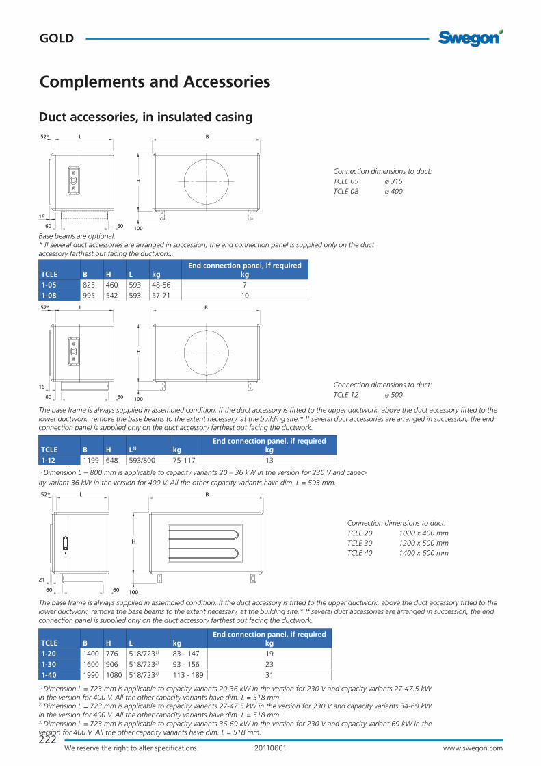
222
GOLD
www.swegon.comWe reserve the right to alter specifications. 20110601
B52*
H
L
100
16
60 60
Complements and Accessories
Duct accessories, in insulated casing
Connection dimensions to duct:TCLE 12 ø 500
TCLE B H L1) kgEnd connection panel, if required
kg1-12 1199 648 593/800 75-117 13
The base frame is always supplied in assembled condition. If the duct accessory is fitted to the upper ductwork, above the duct accessory fitted to the lower ductwork, remove the base beams to the extent necessary, at the building site.* If several duct accessories are arranged in succession, the end connection panel is supplied only on the duct accessory farthest out facing the ductwork.
Connection dimensions to duct:TCLE 05 ø 315 TCLE 08 ø 400
TCLE B H L kgEnd connection panel, if required
kg1-05 825 460 593 48-56 7
1-08 995 542 593 57-71 10
Base beams are optional. * If several duct accessories are arranged in succession, the end connection panel is supplied only on the duct accessory farthest out facing the ductwork.
BL
16
52*
H
10060 60
1) Dimension L = 800 mm is applicable to capacity variants 20 – 36 kW in the version for 230 V and capac-ity variant 36 kW in the version for 400 V. All the other capacity variants have dim. L = 593 mm.
BL
21
52*
H
10060 60
Connection dimensions to duct:TCLE 20 1000 x 400 mmTCLE 30 1200 x 500 mmTCLE 40 1400 x 600 mm
TCLE B H L kgEnd connection panel, if required
kg1-20 1400 776 518/7231) 83 - 147 19
1-30 1600 906 518/7232) 93 - 156 23
1-40 1990 1080 518/7233) 113 - 189 31
The base frame is always supplied in assembled condition. If the duct accessory is fitted to the upper ductwork, above the duct accessory fitted to the lower ductwork, remove the base beams to the extent necessary, at the building site.* If several duct accessories are arranged in succession, the end connection panel is supplied only on the duct accessory farthest out facing the ductwork.
1) Dimension L = 723 mm is applicable to capacity variants 20-36 kW in the version for 230 V and capacity variants 27-47.5 kW in the version for 400 V. All the other capacity variants have dim. L = 518 mm.2) Dimension L = 723 mm is applicable to capacity variants 27-47.5 kW in the version for 230 V and capacity variants 34-69 kW in the version for 400 V. All the other capacity variants have dim. L = 518 mm.3) Dimension L = 723 mm is applicable to capacity variants 36-69 kW in the version for 230 V and capacity variant 69 kW in the version for 400 V. All the other capacity variants have dim. L = 518 mm.

223www.swegon.comWe reserve the right to alter specifications.
GOLD
20110601
Complements and Accessories
Duct accessories, in insulated casing
1) Dimension L = 764 mm is applicable to capacity variants 63 – 79 kW in the version for 230 V and capacity variants 90 - 135 kW in the version for 400 V. All the other capacity variants have dim. L = 604 mm. 2) Dimension L = 760 mm is applicable to capacity variants 69 – 90 kW in the version for 230 V and capacity variant 135 kW in the version for 400 V. All the other capacity variants have dim. L = 617 mm. 3) Casing only. The lower weight applies to dimension L = 604/617 mm and the higher for dim. L = 760/764 mm.
TCLE B H L A kg kg3)
End connection panel, if requiredkg
1-60 2318 1127 604/7641) 28 189 -282 130/152 31
2-80 2637 1320 617/7602) 52 218 - 366 143/166 38
H
BLA* 24**
21100
Connection dimensions to duct:TCLE 60 1600 x 800 mmTCLE 80 1800 x 1,000 mm
The base frame is always supplied in assembled condition. If the duct accessory is fitted to the upper ductwork, above the duct accessory fitted to the lower ductwork, remove the base beams to the extent necessary, at the building site.* If several duct accessories are arranged in succession, the end connection panel is supplied only on the duct acces-sory farthest out facing the ductwork. ** Size 60 only
56* L B
21
H
100
1) Casing only.
TCLE B H L kg kg1)
End connection panel, if requiredkg
1-120 3340 1620 1070 466-591 323 59
Connection dimensions to duct:TCLE 120 2400 x 1,200 mm
* If several duct accessories are arranged in succession, the end connection panel is supplied only on the duct accessory farthest out facing the ductwork.

224
GOLD
www.swegon.comWe reserve the right to alter specifications. 20110601
Complements and Accessories
TCKA Air cooler (water), TCKC (direct expansion)The TCKA/TCKC air coolers are used for cooling the sup-ply air with chilled water or evaporative refrigerant as the cooling medium.
The TCKA/TCKC air cooler is available in several capacity variants that cover existing needs for each size of GOLD unit.
The TCKA air coolers are equipped with connections for insertion sensors and can be used as a multi-purpose coil (cooling and heating).
To be installed for horizontal airflow.
Technical dataInsulated casing. The outer skin is made of galvanized sheet steel painted in a beige colour tone (NCS S2005-Y30R). The inner skin is made of aluminium-zinc plated sheet steel. Environmental class C4.
The TCKA/TCKC air coolers are composed of copper tubes and profiled aluminium fins. The TCKA has headers and water connections made of copper/brass, with male connection threads. The TCKC has headers and distributor tubes made of copper. The connections are designed for brazed joints.
Valve setThe TBVA Valve set consisting of a 2(3)-way valve includ-ing actuator can be ordered.
InstallationThe air cooler should be mounted directly against the air handling unit or insulated duct accessory. Provision for inspection and cleaning must be guaranteed.Connecting the drainage pipework.Electrical connection.
Duct accessories, in insulated casing

225www.swegon.comWe reserve the right to alter specifications.
GOLD
20110601
B 72L52*
H
100
16
60 60
B 82L52*
H
100
16
60 60
Conn. R male threads.
Conn. DN 8 Connection dimensions to duct:TCKA 05 ø 315TCKA 08 ø 400
TCKA B HCapacity variant 1 Capacity variant 2 Capacity variant 4 End connection panel, if required
kgL R kg1) L R kg1) L R kg1)
3-05 825 460 428 DN20 40 428 DN25 42 593 DN25 55 7
3-08 995 542 428 DN25 49 428 DN25 53 593 DN32 80 10
1) Excl. cooling medium
Base beams are optional. * If several duct accessories are arranged in succession, the end connection panel is supplied only on the duct accessory farthest out facing the ductwork.
Drain conn.
ø 28 o.d.
Duct accessories, in insulated casing
Complements and Accessories
TCKC B H LCapacity variant 1 Capacity variant 2 End connection panel, if required
kgdi du kg1) di du kg1)
3-05 825 460 428 1/2" 22 40 5/8" 28 42 7
3-08 995 542 428 5/8" 28 49 5/8" 35 53 10
1) Excl. cooling medium
Base beams are optional. * If several duct accessories are arranged in succession, the end connection panel is supplied only on the duct accessory farthest out facing the ductwork.
Drain conn.
ø 28 o.d.
Outer diam-
eter
du o.d.
Outer diameter
di o.d.
Connection dimensions to duct:TCKC 05 ø 315TCKC 08 ø 400
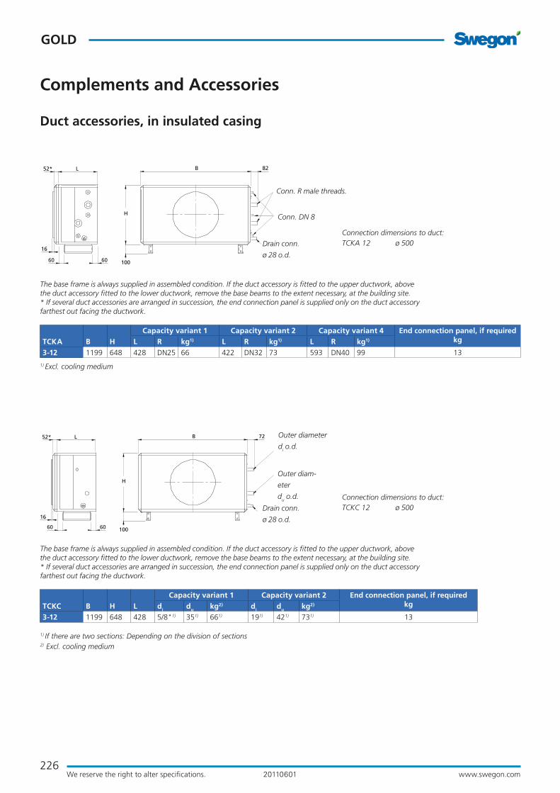
226
GOLD
www.swegon.comWe reserve the right to alter specifications. 20110601
B 82L
16
52*
H
10060 60
Conn. R male threads.
Conn. DN 8
Connection dimensions to duct:TCKA 12 ø 500
TCKA B HCapacity variant 1 Capacity variant 2 Capacity variant 4 End connection panel, if required
kgL R kg1) L R kg1) L R kg1)
3-12 1199 648 428 DN25 66 422 DN32 73 593 DN40 99 13
1) Excl. cooling medium
The base frame is always supplied in assembled condition. If the duct accessory is fitted to the upper ductwork, above the duct accessory fitted to the lower ductwork, remove the base beams to the extent necessary, at the building site.* If several duct accessories are arranged in succession, the end connection panel is supplied only on the duct accessory farthest out facing the ductwork.
Drain conn.
ø 28 o.d.
Duct accessories, in insulated casing
Complements and Accessories
B 72L
16
52*
H
10060 60
Connection dimensions to duct:TCKC 12 ø 500
TCKC B H LCapacity variant 1 Capacity variant 2 End connection panel, if required
kgdi du kg2) di du kg2)
3-12 1199 648 428 5/8"1) 351) 661) 191) 421) 731) 13
1) If there are two sections: Depending on the division of sections
2) Excl. cooling medium
The base frame is always supplied in assembled condition. If the duct accessory is fitted to the upper ductwork, above the duct accessory fitted to the lower ductwork, remove the base beams to the extent necessary, at the building site.* If several duct accessories are arranged in succession, the end connection panel is supplied only on the duct accessory farthest out facing the ductwork.
Drain conn.
ø 28 o.d.
Outer diam-
eter
du o.d.
Outer diameter
di o.d.

227www.swegon.comWe reserve the right to alter specifications.
GOLD
20110601
BL
21
52*
H
100
82
60 60
Duct accessories, in insulated casing
Complements and Accessories
TCKA B HCap. variant 1 Cap. variant 2 Cap. variant 3 Cap. variant 4 End connection panel, if required
kgL R kg1) L R kg1) L R kg1) L R kg1)
4-20 1400 776 468 DN32 85 468 DN32 94 593 DN40 114 593 DN50 123 19
4-30 1600 906 468 DN32 103 468 DN40 117 593 DN50 143 593 DN60 158 23
4-40 1990 1080 468 DN40 136 468 DN50 158 593 DN65 193 593 DN80 217 31
1) Excl. cooling medium
The base frame is always supplied in assembled condition. If the duct accessory is fitted to the upper ductwork, above the duct accessory fitted to the lower ductwork, remove the base beams to the extent necessary, at the building site.* If several duct accessories are arranged in succession, the end connection panel is supplied only on the duct acces-sory farthest out facing the ductwork.
Connection dimensions to duct:TCKA 20 1000 x 400 mmTCKA 30 1200 x 500 mmTCKA 40 1400 x 600 mm
Conn. R male threads.
Conn. DN 8
Drain conn.
ø 28 o.d.
Connection dimensions to duct:TCKC 20 1000 x 400 mmTCKC 30 1200 x 500 mmTCKC 40 1400 x 600 mm
BL
21
52*
H
100
72
60 60
Drain conn.
ø 28 o.d.
Outer diam-
eter
du o.d.
Outer diameter
di o.d.
TCKC B H LCap. variant 1 Cap. variant 2 End connection panel, if required
kgdi du kg2) di du kg2)
3-20 1400 776 468 221) 421) 301) 281) 541) 391) 19
3-30 1600 906 468 281) 541) 441) 281) 541) 561) 23
3-40 1990 1080 468 281) 541) 631) 281) 541) 831) 31
1) If there are two sections: Depending on the division of sections
2) Excl. cooling medium
The base frame is always supplied in assembled condition. If the duct accessory is fitted to the upper ductwork, above the duct accessory fitted to the lower ductwork, remove the base beams to the extent necessary, at the building site.* If several duct accessories are arranged in succession, the end connection panel is supplied only on the duct acces-sory farthest out facing the ductwork.

228
GOLD
www.swegon.comWe reserve the right to alter specifications. 20110601
21
B
H
100
L 105A* 24**
21
B 95
H
100
LA* 24**
TCKA B H L A
Capacity variant 1 Capacity variant 2 Capacity variant 3 Capacity variant 4 End connection panel, if requiredkgR kg1) kg2) R kg1) kg2) R kg1) kg2) R kg1) kg2)
3-60 2318 1127 542 28 DN65 202 111 DN65 214 111 - - 111 - - 111 31
3-80 2637 1320 542 52 DN65 268 135 DN65 282 135 DN65 302 135 DN65 324 135 38
Connection dimensions to duct:TCKA 60 1600 x 800 mmTCKA 80 1800 x 1,000 mm
Connection dimensions to duct:TCKC 60 1600 x 800 mmTCKC 80 1800 x 1,000 mm
TCKC B H L A
Capacity variant 1 Capacity variant 2 Capacity variant 3 End connection panel, if requiredkgkg1) kg2) kg1) kg2) kg1) kg2)
3-60 2318 1127 542 28 202 111 214 111 229 111 31
3-80 2637 1320 542 52 263 135 282 135 324 135 38
1) Including casing, not charged with refrigerant.2) Casing only.
1) Including casing, not charged with refrigerant.2) Casing only.
Conn. R male threads.
Conn. DN 8
Drain pipe
conn. DN 25
male threads
Drain pipe
conn. DN 25
male threads
TCKA B H L A
Capacity variant 5 Capacity variant 6 End connection panel, if requiredkgR kg1) kg2) R kg1) kg2)
3-60 2318 1127 542 28 DN65 229 111 DN65 245 111 31
Duct accessories, in insulated casing
Complements and Accessories
The base frame is always supplied in assembled condition. If the duct accessory is fitted to the upper ductwork, above the duct accessory fitted to the lower ductwork, remove the base beams to the extent necessary, at the building site.* If several duct accessories are arranged in succession, the end connection panel is supplied only on the duct accessory farthest out facing the ductwork. ** Size 60 only
The base frame is always supplied in assembled condition. If the duct accessory is fitted to the upper ductwork, above the duct accessory fitted to the lower ductwork, remove the base beams to the extent necessary, at the building site.* If several duct accessories are arranged in succession, the end connection panel is supplied only on the duct accessory farthest out facing the ductwork. ** Size 60 only
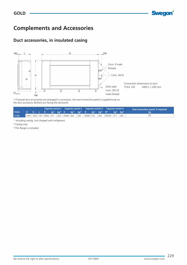
229www.swegon.comWe reserve the right to alter specifications.
GOLD
20110601
56* L B
21
H
100
105
TCKA B H L
Capacity variant 1 Capacity variant 2 Capacity variant 3 Capacity variant 4 End connection panel, if requiredkgR kg1) kg2) R kg1) kg2) R kg1) kg2) R3) kg1) kg2)
3-120 3340 1620 720 DN65 417 260 DN80 464 260 DN80 516 260 DN100 571 260 59
Connection dimensions to duct:TCKA 120 2400 x 1,200 mm
1) Including casing, not charged with refrigerant.2) Casing only.3) The flange is included.
Conn. R male
threads.
Conn. DN 8
Drain pipe
conn. DN 25
male threads
* If several duct accessories are arranged in succession, the end connection panel is supplied only on the duct accessory farthest out facing the ductwork.
Complements and Accessories
Duct accessories, in insulated casing

230
GOLD
www.swegon.comWe reserve the right to alter specifications. 20110601
TCEK Coil section Electric heating and water-borne coolingThe TCEK coil section is used for heating/cooling the supply air. The air heater runs on electric power and its type designation is TCLE. The cooling coil is a type TCKA air cooler for chilled water or a type TCKA air cooler for evaporative refrigerant. The type TCKA air coolers are equipped with connections for insertion sensors and can be used as a multi-purpose coil (cooling and heating).
To be installed for horizontal airflow.
The integrated thyristor is controlled via signals from the GOLD air handling unit. The conductors for the two series-coupled overheating protections and control signal transmission are connected by means of a quick connec-tor to the GOLD unit.
Technical dataInsulated casing. The outer skin is made of galvanized sheet steel painted in a beige colour tone (NCS S2005-Y30R). The inner skin is made of aluminium-zinc plated sheet steel. Environmental class C4.
The electric air heater is available in several capacity vari-ants; the electrical equipment conforms to the provisions of Degree of Protection IP43.
The air cooler is composed of copper tubes and profiled aluminium fins. The air cooler for chilled water has head-ers and water connections made of copper/brass, with male connection threads.
The air cooler for evaporative refrigerant has headers and distributor tubes made of copper. The connections are designed for brazed joints.
The air cooler is available in several capacity variants that cover existing needs for each size of GOLD unit.
Valve setThe TBVA Valve set can be ordered for the air cooler. The set consists of a 2(3)-way valve and includes the valve actuator.
InstallationThe coil section should be mounted directly against the air handling unit or insulated duct accessory. Provision for inspection and cleaning must be guaranteed.Electrical connection. Power must be supplied to the electric air heater directly from an electrical distri-bution box.
Complements and Accessories
Duct accessories, in insulated casing

231www.swegon.comWe reserve the right to alter specifications.
GOLD
20110601
B
16
52* L
H
10060 60
B52* L
H
100
16
55 55
Complements and Accessories
Duct accessories, in insulated casing
Connection dimensions to duct:TCEK 12 ø 500
The base frame is always supplied in assembled condition. If the duct accessory is fitted to the upper ductwork, above the duct accessory fitted to the lower ductwork, remove the base beams to the extent necessary, at the building site.* If several duct accessories are arranged in succession, the end connection panel is supplied only on the duct accessory farthest out facing the ductwork.
Connection dimensions to duct:TCEK 05 ø 315 TCEK 08 ø 400
Base beams are optional. * If several duct accessories are arranged in succession, the end connection panel is supplied only on the duct accessory farthest out facing the ductwork.
TCEK B H L kg 1)
End connection panel, if requiredkg
3-05 825 460 1409 103-117 7
3-08 995 542 1409 124-156 10
TCEK B H L kg 1)
End connection panel, if requiredkg
3-122) 1199 648 1420 169-207 13
3-122) 1199 648 1873 220-232 13
3-122) 1199 648 2038 252-266 13
1) Not charged with refrigerant.For particulars of the pipe dimensions, see the corresponding TCKA or TCKC.
1) Not charged with refrigerant.2) Dimension L = 2,038 mm is applicable to air heater capacity variants 20 - 36 kW in the version for 230 V and capacity variant 36 kW in the version for 400 V in combination with air cooler in capacity variant 4.Dimension L = 1,873 mm is applicable to air heater capacity variants 20 - 36 kW in the version for 230 V and capacity variant 36 kW in the version for 400 V in combination with air cooler in capacity variant 1 or 2. Dimension L = 1,420 mm is applicable to other combinations of capacity variants.

232
GOLD
www.swegon.comWe reserve the right to alter specifications. 20110601
H
100
BL 24**A*
21
BL
21
52*
H
10060 60
1) Casing only.2) Including casing, not charged with refrigerant.3) Dimension L = 1,848 mm is applicable to capacity variants 63 – 79 kW in the version for 230 V and capacity variants 90 - 135 kW in the version for 400 V. All the other capacity variants have dim. L = 1,688 mm. 4) Dimension L = 1,843 mm is applicable to capacity variants 69 – 90 kW in the version for 230 V and capacity variant 135 kW in the version for 400 V. All the other capacity variants have dim. L = 1,700 mm. For particulars of the pipe dimensions, see the corresponding TCKA or TCKC.
TCEK B H L A kg 1) kg 2)
End connection panel, if requiredkg
3-603) 2318 1127 1688 28 365 515 - 597 31
3-603) 2318 1127 1848 28 387 593 - 651 31
3-804) 2637 1320 1700 52 416 619 - 719 38
3-804) 2637 1320 1843 52 439 767 - 828 38
Connection dimensions to duct:TCEK 60 1600 x 800 mmTCEK 80 1800 x 1,000 mm
The base frame is always supplied in assembled condition. If the duct accessory is fitted to the upper ductwork, above the duct accessory fitted to the lower ductwork, remove the base beams to the extent necessary, at the building site.* If several duct accessories are arranged in succession, the end connection panel is supplied only on the duct accessory farthest out facing the ductwork. ** Size 60 only
Complements and Accessories
Duct accessories, in insulated casing
Connection dimensions to duct:TCEK 20 1000 x 400 mmTCEK 30 1200 x 500 mmTCEK 40 1400 x 600 mm
1) Including casing, not charged with refrigerant.2) Dimension L = 1,733 mm is applicable to capacity variants 20-36 kW in the version for 230 V and capacity variants 27-47.5 kW in the version for 400 V. All the other capacity variants have dim. L = 1,608 mm. 3) Dimension L = 1,733 mm is applicable to capacity variants 20-47.5 kW in the version for 230 V and capacity vari-ants 34-69 kW in the version for 400 V. All the other capacity variants have dim. L = 1,608 mm. 4) Dimension L = 1,733 mm is applicable to capacity variants 36-69 kW in the version for 230 V and capacity variant 69 kW in the version for 400 V. All the other capacity variants have dim. L = 1,608 mm. For particulars of the pipe dimensions, see the corresponding TCKA or TCKC.
TCEK B H L kg 1)
End connection panel, if requiredkg
3-202) 1400 776 1608 229 - 265 19
3-202) 1400 776 1733 258 - 317 19
3-303) 1600 906 1608 265 - 319 23
3-303) 1600 906 1733 289 - 365 23
3-404) 1990 1080 1608 334 - 423 31
3-404) 1990 1080 1733 371 - 473 31
The base frame is always supplied in assembled condition. If the duct accessory is fitted to the upper ductwork, above the duct accessory fitted to the lower ductwork, remove the base beams to the extent necessary, at the building site.* If several duct accessories are arranged in succession, the end connection panel is supplied only on the duct accessory farthest out facing the ductwork.

233www.swegon.comWe reserve the right to alter specifications.
GOLD
20110601
56* L B
21
H
100
1) Casing only.2) Including casing, not charged with refrigerant.For particulars of the pipe dimensions, see the corresponding TCKA or TCKC.
TCEK B H L kg 1) kg 2)
End connection panel, if requiredkg
3-120 3340 1620 2290 789 1015-1230 59
Connection dimensions to duct:TCEK 120 2400 x 1,200 mm
* If several duct accessories are arranged in succession, the end connection panel is supplied only on the duct accessory farthest out facing the ductwork.
Complements and Accessories
Duct accessories, in insulated casing

234
GOLD
www.swegon.comWe reserve the right to alter specifi cations. 20110601
Coil section TCLK Waterborne heating and coolingThe TCLK coil section is used for heating/cooling the sup-ply air. The air heater is for hot water and its type desig-nation is TCLA. The air cooler is of type TCKA for chilled water or of type TCKC for evaporative refrigerant. The type TCKA air coolers are equipped with connections for insertion sensors and can be used as a multi-purpose coil (cooling and heating).
To be installed for horizontal airfl ow.
Technical dataInsulated casing. The outer skin is made of galvanized sheet steel painted in a beige colour tone (NCS S2005-Y30R). The inner skin is made of aluminium-zinc plated sheet steel. Environmental Class C4.The air heater is a fi nned-tube heat exchanger fabricated of copper tubes and profi led aluminium fi ns. The headers and the pipework to the water connections are made of copper. The male threaded pipe connections are made of brass.
The air heater is available in three capacity variants. Ca-pacity variant 1 provides the lowest capacity and capacity variant 3 provides the highest capacity.
The air heaters and air coolers are equipped with individ-ual plugs for venting and drainage. A separate connection is provided for an anti-frost monitor sensor.
The air cooler is composed of copper tubes and profi led aluminium fi ns. The air cooler for chilled water has head-ers and water connections made of copper/brass, with male connection threads.
The air cooler for evaporative refrigerant has headers and distributor tubes made of copper. The connections are designed for brazed joints.
The air cooler is available in several capacity variants that cover existing needs for each size of GOLD unit.
Valve set Valve set with 2(3)-way valve, actuator, anti-frost protec-tion sensor and connection cable with quick-fi t connector can be ordered. If you use a valve of your own, you have the option of instead selecting a set of electrical connec-tion components. This set contains a connection cable with quick-fi t connector, resistor and insertion or strap-on sensor.
Complements and Accessories
Duct accessories, in insulated casing
Extra accessoriesA circulation pump is used for guaranteeing the frost guard function, if air heaters without anti-frost burst protection are used. Supplied with T coupling, non-return valve and adjustment valve. The automatic pump control system is integrated into the control equipment of the GOLD unit.
InstallationThe coil section should be mounted directly against the air handling unit or insulated duct accessory. Provision for inspection and cleaning must be guaranteed.
Electrical connection.
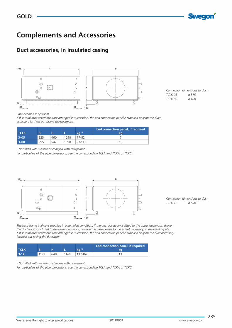
235www.swegon.comWe reserve the right to alter specifications.
GOLD
20110601
B
16
52* L
H
10060 60
B52* L
H
100
16
81 81
Complements and Accessories
Duct accessories, in insulated casing
Connection dimensions to duct:TCLK 12 ø 500
The base frame is always supplied in assembled condition. If the duct accessory is fitted to the upper ductwork, above the duct accessory fitted to the lower ductwork, remove the base beams to the extent necessary, at the building site.* If several duct accessories are arranged in succession, the end connection panel is supplied only on the duct accessory farthest out facing the ductwork.
Connection dimensions to duct:TCLK 05 ø 315 TCLK 08 ø 400
Base beams are optional. * If several duct accessories are arranged in succession, the end connection panel is supplied only on the duct accessory farthest out facing the ductwork.
TCLK B H L kg 1)
End connection panel, if requiredkg
3-05 825 460 1098 77-82 7
3-08 995 542 1098 97-113 10
TCLK B H L kg 1)
End connection panel, if requiredkg
3-12 1199 648 1148 137-162 13
1) Not filled with water/not charged with refrigerant.For particulars of the pipe dimensions, see the corresponding TCLA and TCKA or TCKC.
1) Not filled with water/not charged with refrigerant.For particulars of the pipe dimensions, see the corresponding TCLA and TCKA or TCKC.
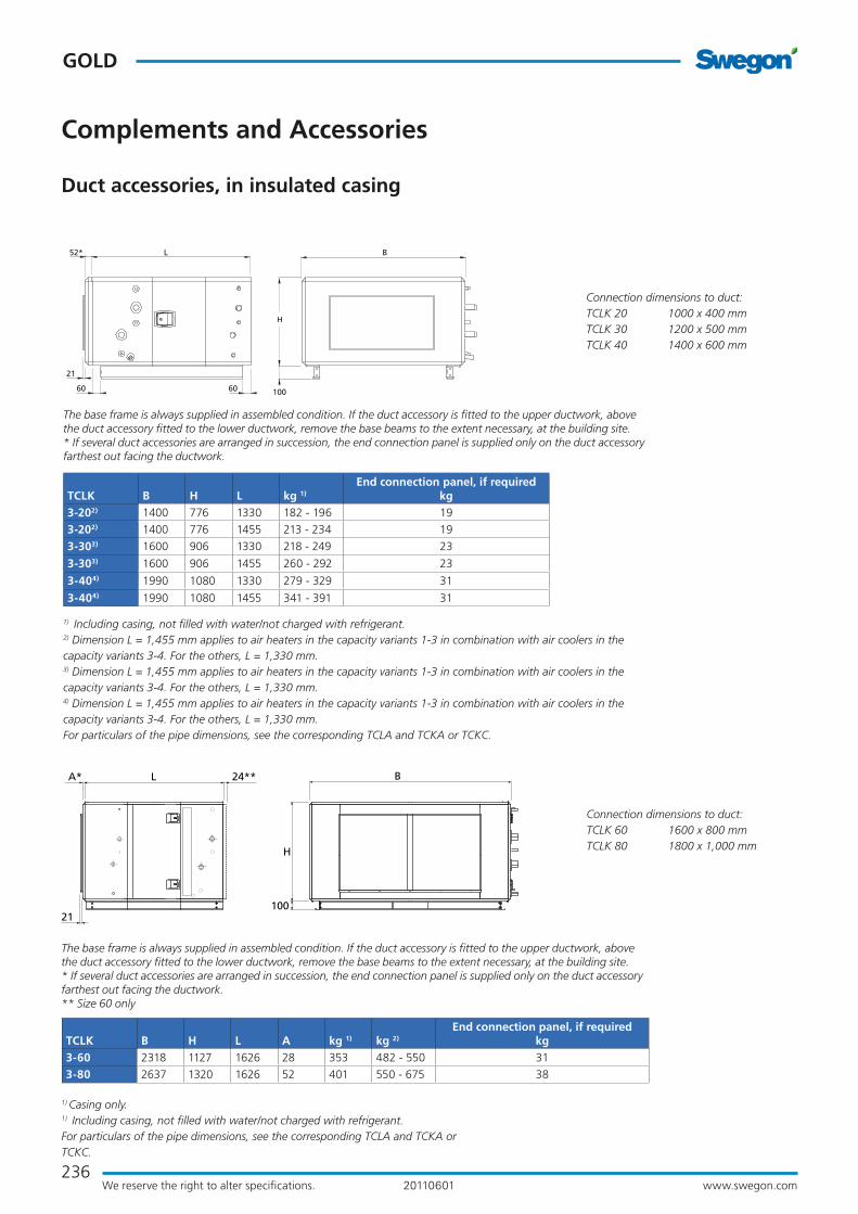
236
GOLD
www.swegon.comWe reserve the right to alter specifications. 20110601
H
100
BL
21
24**A*
BL
21
52*
H
10060 60
Complements and Accessories
Duct accessories, in insulated casing
1) Casing only. 1) Including casing, not filled with water/not charged with refrigerant.For particulars of the pipe dimensions, see the corresponding TCLA and TCKA or TCKC.
TCLK B H L A kg 1) kg 2)
End connection panel, if requiredkg
3-60 2318 1127 1626 28 353 482 - 550 31
3-80 2637 1320 1626 52 401 550 - 675 38
Connection dimensions to duct:TCLK 60 1600 x 800 mmTCLK 80 1800 x 1,000 mm
The base frame is always supplied in assembled condition. If the duct accessory is fitted to the upper ductwork, above the duct accessory fitted to the lower ductwork, remove the base beams to the extent necessary, at the building site.* If several duct accessories are arranged in succession, the end connection panel is supplied only on the duct accessory farthest out facing the ductwork. ** Size 60 only
Connection dimensions to duct:TCLK 20 1000 x 400 mmTCLK 30 1200 x 500 mmTCLK 40 1400 x 600 mm
1) Including casing, not filled with water/not charged with refrigerant.2) Dimension L = 1,455 mm applies to air heaters in the capacity variants 1-3 in combination with air coolers in the capacity variants 3-4. For the others, L = 1,330 mm. 3) Dimension L = 1,455 mm applies to air heaters in the capacity variants 1-3 in combination with air coolers in the capacity variants 3-4. For the others, L = 1,330 mm. 4) Dimension L = 1,455 mm applies to air heaters in the capacity variants 1-3 in combination with air coolers in the capacity variants 3-4. For the others, L = 1,330 mm. For particulars of the pipe dimensions, see the corresponding TCLA and TCKA or TCKC.
TCLK B H L kg 1)
End connection panel, if requiredkg
3-202) 1400 776 1330 182 - 196 19
3-202) 1400 776 1455 213 - 234 19
3-303) 1600 906 1330 218 - 249 23
3-303) 1600 906 1455 260 - 292 23
3-404) 1990 1080 1330 279 - 329 31
3-404) 1990 1080 1455 341 - 391 31
The base frame is always supplied in assembled condition. If the duct accessory is fitted to the upper ductwork, above the duct accessory fitted to the lower ductwork, remove the base beams to the extent necessary, at the building site.* If several duct accessories are arranged in succession, the end connection panel is supplied only on the duct accessory farthest out facing the ductwork.

237www.swegon.comWe reserve the right to alter specifications.
GOLD
20110601
56* L B
21
H
100
1) Casing only. 1) Including casing, not filled with water/not charged with refrigerant.For particulars of the pipe dimensions, see the corresponding TCLA and TCKA or TCKC.
TCLK B H L kg 1) kg 2)
End connection panel, if requiredkg
3-120 3340 1620 1940 722 962-1206 59
Connection dimensions to duct:TCLK 120 2400 x 1,200 mm
* If several duct accessories are arranged in succession, the end connection panel is supplied only on the duct accessory farthest out facing the ductwork.
Complements and Accessories
Duct accessories
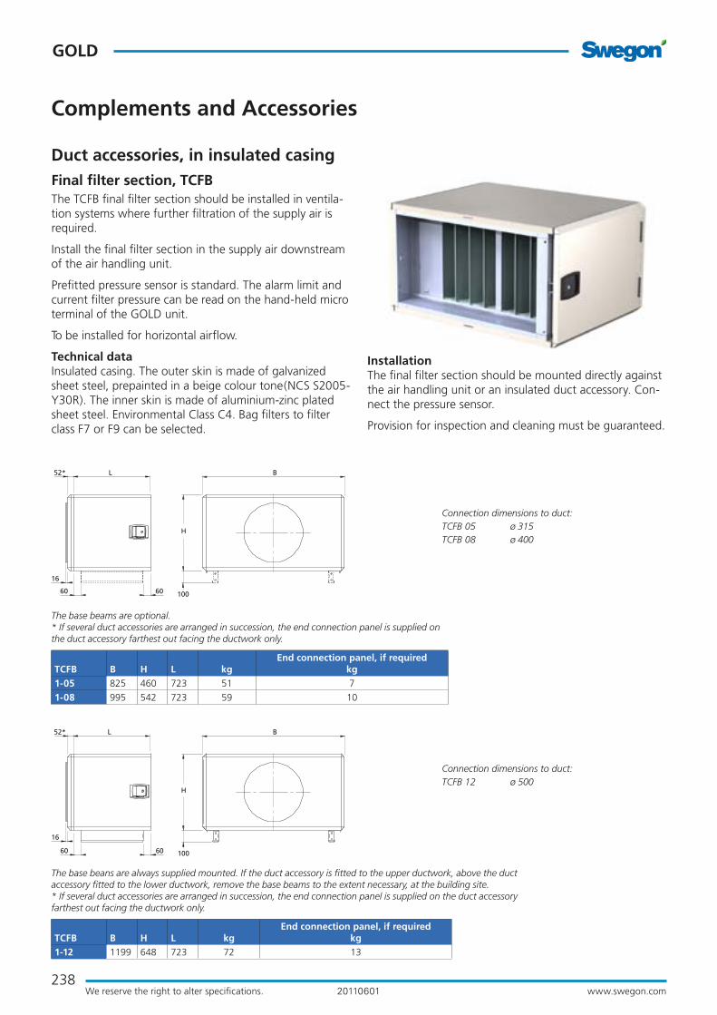
238
GOLD
www.swegon.comWe reserve the right to alter specifications. 20110601
Complements and Accessories
Duct accessories, in insulated casingFinal filter section, TCFBThe TCFB final filter section should be installed in ventila-tion systems where further filtration of the supply air is required.
Install the final filter section in the supply air downstream of the air handling unit.
Prefitted pressure sensor is standard. The alarm limit and current filter pressure can be read on the hand-held micro terminal of the GOLD unit.
To be installed for horizontal airflow.
Technical dataInsulated casing. The outer skin is made of galvanized sheet steel, prepainted in a beige colour tone(NCS S2005-Y30R). The inner skin is made of aluminium-zinc plated sheet steel. Environmental Class C4. Bag filters to filter class F7 or F9 can be selected.
Connection dimensions to duct:TCFB 12 ø 500
TCFB B H L kgEnd connection panel, if required
kg1-12 1199 648 723 72 13
The base beans are always supplied mounted. If the duct accessory is fitted to the upper ductwork, above the duct accessory fitted to the lower ductwork, remove the base beams to the extent necessary, at the building site.* If several duct accessories are arranged in succession, the end connection panel is supplied on the duct accessory farthest out facing the ductwork only.
Connection dimensions to duct:TCFB 05 ø 315 TCFB 08 ø 400
TCFB B H L kgEnd connection panel, if required
kg1-05 825 460 723 51 7
1-08 995 542 723 59 10
The base beams are optional. * If several duct accessories are arranged in succession, the end connection panel is supplied on the duct accessory farthest out facing the ductwork only.
BL52*
H
100
16
60 60
BL
16
52*
H
10060 60
InstallationThe final filter section should be mounted directly against the air handling unit or an insulated duct accessory. Con-nect the pressure sensor.
Provision for inspection and cleaning must be guaranteed.

239www.swegon.comWe reserve the right to alter specifications.
GOLD
20110601
21
B
H
100
LA* 24**
56* L B
21
H
100
BL
21
52*
H
10060 60
Complements and Accessories
Duct accessories, in insulated casing
Connection dimensions to duct:TCFB 60 1600 x 800 mmTCFB 80 1800 x 1000 mm
The base beans are always supplied mounted. If the duct accessory is fitted to the upper ductwork, above the duct accessory fitted to the lower ductwork, remove the base beams to the extent necessary, at the building site.* If several duct accessories are arranged in succession, the end connection panel is supplied on the duct accessory farthest out facing the ductwork only.** Size 60 only
TCFB B H L A kgEnd connection panel, if required
kg1-60 2318 1127 764 28 193 31
1-80 2637 1320 760 52 222 38
Connection dimensions to duct:TCFB 20 1000 x 400 mmTCFB 30 1200 x 500 mmTCFB 40 1400 x 600 mm
The base beans are always supplied mounted. If the duct accessory is fitted to the upper ductwork, above the duct accessory fitted to the lower ductwork, remove the base beams to the extent necessary, at the building site.* If several duct accessories are arranged in succession, the end connection panel is supplied on the duct accessory farthest out facing the ductwork only.
TCFB B H L kgEnd connection panel, if required
kg1-20 1400 776 723 88 19
1-30 1600 906 723 109 23
1-40 1990 1080 723 136 31
Connection dimensions to duct:TCFB 120 2400 x 1200 mm
* If several duct accessories are arranged in succession, the end connection panel is sup-plied on the duct accessory farthest out facing the ductwork only.
TCFB B H L kgEnd connection panel, if required
kg1-120 3340 1620 720 343 59

240
GOLD
www.swegon.comWe reserve the right to alter specifications. 20110601
Carbon cartridges
TBFK Carbon filter sectionThe TBFK has activated carbon filter medium designed for improving the air quality indoors by adsorbing gaseous, harmful or foul-smelling substances from the air.
Note that we cannot guarantee one hundred percent elimination of odours due to variations in the impurities and mixtures of various chemical substances arrested in the filter.
The carbon filter cartridges are disposable. They are sea-ted in mounting frames and can be locked in their bayo-net socket by simply turning them by hand. The cartridges contain a filter mat made of polyester, which encloses the activated carbon.
The frame structure consists of 38 mm galvanized (Send-zimir) square profiled sections, painted in RAL 7032. The profiled sections are held together by corner pieces made of plastic.
The outer and inner skins of the cover panels and inspec-tion doors consist of galvanized sheet steel. An interven-ing 45 mm thick slab of thermal and sound-attenuating insulation is sandwiched between the skins. .
The cover panels can be dismantled from the unit.
The inspection doors have hinges and handles.
After fabrication the panels and inspection doors are given powder painted, min. 60 µm finish, RAL 7032. This leaves no open sectional areas and provides excellent cor-rosion resistance.
InstallationThe TBFK carbon filter section has a connection frame for
Note that the TBFK carbon filter is available in
six sizes and that the slip-clamp connection
dimensions follow the connection dimensions
of the GOLD air handling units.
c
Complements and Accessories
Duct accessories
slip-clamp jointing and is designed for installation in the ductwork, see adjacent illustration.
TBFK Slip-clamp
conn.
widthxheigh
B H L kg
without
cartridges
Number of
cartridges
kg
with
cartridges017 900x400 994 535 765 75 17 113
024 1100x500 1224 612 765 89 24 143
036 1300x600 1453 688 765 104 36 185
050 1500x700 1606 841 765 120 50 233
072 1800x900 1912 994 765 144 72 307
098 2100x900 2218 1147 765 172 98 393
B
H
L

241www.swegon.comWe reserve the right to alter specifications.
GOLD
20110601
C
G
A
BD D
E
H
TBHA Outdoor air hood Designed for the intake of outdoor air. The design of the hood obstructs snow and raindrop entrainment. The hood is hinged and has air intake wire screens on both sides. For GOLD sizes 04-40.
TBHB Exhaust air hood Designed for the discharge of exhaust air. The hood can be opened on hinges and is equipped with air deflectors that effectively direct the exhaust air upward and give the air high discharge velocity. To achieve low pressure drop, the air deflectors are rounded off on both their long sides. The hoods are equipped with effective provision for drainage. For GOLD sizes 04-40.
TBHC Dual-purpose hoodThe TBHC is a combination of TBHA outdoor air hood and TBHB exhaust air hood and is available for the size 04 - 12 GOLD units only.
Complements and Accessories
Roof hoods and exterior wall hoods
TBHA Outdoor air hood
TBHB Exhaust air hood
TBHC Dual-pur-pose hood
Common for all roof hoodsThe hoods are made of aluminium-zinc plated sheet steel covered with a Plastisol (black) surface coating that conforms to Environmental Class C4.
The roof duct is made of galvanized sheet steel. It is lined inside with 50 mm thick insulation to Fire-resist-ance Class EI30, with a surface covering of type-ap-proved synthetic woven fabric. Two angle brackets for
connection to the relevant roof having client-specified slope are included.
The hoods for the size 04-12 GOLD units have circular duct connection fitted with type-approved rubber ring seal for jointing to spiral ductwork.
The hoods for the size 14-40 GOLD units have rectan-gular duct connection for slip-clamp joint connection.
H
E
C
DB
A
B
2 angle brackets (unmounted) are included in the supply.
TBHA Outdoor air hood and TBHB Exhaust air hood TBHC Dual-purpose hood
2 angle brackets (unmounted) are included in the supply.
For GOLD A B C D E H kg04/05 500 400 850 Ø315 620 800 31
07/08 600 500 950 Ø400 620 800 44
11/12 820 700 1300 Ø500 850 1200 129
14/20 820 700 1300 600 850 1200 129
25 - 40 1120 1000 1700 900 1150 1200 148
For GOLD A B C D E H G kg04/05 1000 900 850 Ø315 620 800 400 70
07/08 1200 1100 950 Ø400 620 800 500 100
11/12 1600 1500 1300 Ø500 850 1200 700 290

242
GOLD
www.swegon.comWe reserve the right to alter specifications. 20110601
TBHE Exterior wall hoodThe exterior wall hood is designed for the admission of outdoor air and the discharge of exhaust air. The exhaust air is horizontally discharged through a circular wire mesh grille at the front of the hood. Outdoor air is admitted through a wire mesh grille at the bottom of the hood.
This design effectively prevents short-circuit flow between the outdoor air/exhaust air. For GOLD sizes 04 - 12.
The TBHE exterior wall hoods are made of aluminium-zinc plated sheet steel covered with a Plastisol (light grey) sur-face coating that conforms to Environmental Class C4.
Complements and Accessories
Roof hoods and exterior wall hoods
TBHE Exterior wall hoodL
c/c
D
H
D
B
< Can be reversed. >Outdoor airExhaust air
For GOLD B c/c D H L kg04/05 200 420 Ø315 520 950 11
07/08 250 500 Ø400 580 1150 15
11/12 300 600 Ø500 750 1350 20
TCWP Component boxThe TCWP component box is intended for the incorpo-ration of components which must be protected from weather or mechanical damage. Typical components are valves, actuators, etc.
The component box consists of a GOLD-type casing. The component box is enclosed on all sides and has an inspec-tion door that can be selected as a right or left-hinged door.
A roof is available as an accessory for outdoor installation.
The cutting of openings for e.g. pipes and electric cables, if required, must be done at the building site.
B827
H
100112 112 J50 50
Size B H J kg05 825 460 561 54
12 1199 648 935 88
30 1600 906 1336 128
40 1990 1080 1726 160
The base beams are optional extras for the size 05 (Standard on the other sizes).

243www.swegon.comWe reserve the right to alter specifications.
GOLD
20110601
GeneralThe GOLD air handling units, including TCBR air recircula-tion section and COOL DX/DXS cooling unit accessories, can be installed outdoors. This presupposes that the roof, air intake section and exhaust air hood accessories are used. GOLD air handling units cannot be installed out-doors in applications that call for the fan outlet/inlet to be positioned on the top of the unit.
TBTB RoofThe roof is supplied in kit form, complete with the neces-sary assembly parts and sealing strips. The cover plates for all the door handles are included as standard.
The the visible components are made of sheet metal painted in a shade of beige (NCS S2005-Y30R).
Dimensions
TBTF Intake air section with pre-filter (sizes 04-40)The TBTF intake air section is made of aluminium-zinc plated sheet steel. The intake air section has a fixed grille and has a hole for drainage. The intake air section has rectangular dimensions and the air handling unit is sup-plied without the end connection for intake air (so-called full face, not GOLD SD size 04/05, 08, 14/20, 25/30 and 35/40). The intake air section has a flange with predrilled holes and is meant to be secured by means of screws to the air handling unit. Orders can be placed for filter and damper installed in the air intake section. The filter is of class G2 compact type and serves also as a moisture trap. Damper actuator can be ordered with spring return or with modulating function.
TBTA Intake air section (sizes 50-120)The TBTA intake air section is made of aluminium-zinc plated sheet steel. The intake air section has a fixed louvre grille that effectively prevents raindrops from entering the duct and is equipped with holes for drainage. The intake air section has rectangular dimensions for all the sizes of GOLD and has space inside for an intake damper, if re-quired. The intake air section has a flange with predrilled holes and is meant to be secured by means of screws to the end wall panel of the air handling unit.
TBTA Exhaust air hoodThe TBTA exhaust air hood is made of aluminium-zinc plated sheet steel. The exhaust air hood is equipped with protective netting. The hood is circular for sizes 04 - 12, and rectangular with slip-clamp connection for the other sizes (the slip clamps are included).
GOLD CX Cover hoodCover hood that protects the pipework package on the GOLD CX installed outdoors (does not apply to sizes 100/120). Visible parts are made of sheet steelpainted in a beige colour tone, NCS S2005-Y 30R.
Duct AccessoriesSelect duct accessories housed in insulated casings if they are to be installed outdoors. They can be located outdoors, however the enclosure classes and permissible ambient temperatures of any actuators included must be taken into consideration. See the instructions for the cor-responding accessory. If necessary, see to it that required protection is arranged.
Installation TipsGOLD Air handling units should if possible be installed where the most favourable conditions exist from a weath-er point of view.
The ductwork for supply air and extract air must be insulated in accordance with local standards. If internally insulated ducts are used, the TBLZ-1-65 countersink kit should be used so that the measurement probe of the GOLD unit’s supply air sensor will reach sufficiently far into the duct.
The hand-held micro terminal of the GOLD unit is sensi-tive to cold and must always be kept in a heated space. If required, use an extension cable or also an extension cable kit (see accessories for electrical and control equip-ment).
Swegon recommends moving the exhaust air hood a distance from the air handling unit by fitting a straight length of duct between them, especially if the exhaust air leaves the air handling unit from its lower level. This will prevent the risk of exhaust air shortcircuiting to the outdoor air and the risk of water entering the ventilation system.
Complements and Accessories
Outdoor installation
GOLD units equipped with the roof, air intake section and exhaust air hood accessories can be installed outdoors. The roof cannot be used on GOLD air handling units with the fan outlet/inlet positioned on the top of the unit.
27
50-200 50-200 5510 108
Exhaust air
Outdoor air
Extract air
Supply air

244
GOLD
www.swegon.comWe reserve the right to alter specifications. 20110601
710 (04/05)745 (08)
A
B
Mechanical equipment
Complements and Accessories
GOLD Sizes 04/05 and 07/08StandGOLD RX, rotary heat exchangerGOLD SD, Supply air and extract air handling unitsSpecially designed stand, whose height makes it possible to arrange ducts under the air handling unit.
The stand is made of galvanized sheet steel profiled sec-tions. The stand is supplied in assembly kit form. The long sides (A in the illustration) are used for horizontal installa-tion and the shorter sides (B) are used for vertical installa-tion.
Set of support legsGOLD PX (plate heat exchanger)Specially designed set of legs, the height (745 mm, all sizes) of which makes it possible to arrange ducts under the air handling unit.
The set of legs consists of four legs made of galvanized sheet steel profiled sections. The legs are secured by means of bolts under the air handling unit.
Elevating block for base beamsGOLD PX, plate heat exchangerThe base beams of the GOLD PX air handling units, sizes 04-08, are 180 mm high and the base beams of the insulated duct accessories are 100 mm high. An elevating bock for base beams (80 mm) must be fitted to elevate the insulated duct accessory and align it with the air han-dling unit.
Base frame, (base beams) for the COOL DX 08Specially designed stand with legs. Also used as base beams in combination with the GOLD PX
Cover holderThe cover holder facilitates the servicing and maintenance of vertically installed units. It consists of a mechanic stay with latch and is supplied in unmounted condition.
Stand for the GOLD RX/SD, Sizes 04/05 and 08.
GOLD CX/SD sizes 14/20, 25/30, 35/40, 50/60, 70/80, 100/120Droplet eliminatorTo prevent the condensate from being entrained by the air flow at velocities exceeding 3 m/s, coil heat exchangers can be equipped with droplet eliminator on the extract air side.
The material in the droplet eliminator is GLASdek, which is fire resistant and highly absorbent. The pressure drop across the droplet eliminator is low. On delivery, the dro-plet eliminator is mounted.
80
Elevating block for base beams
Insulated duct accessory
Base beam

245www.swegon.comWe reserve the right to alter specifications.
GOLD
20110601
For GOLD A B kg14/20 458 1058 5
25/30 558 1258 5,5
35/40 658 1458 6,5
50/60 858 1658 8
70/80 1058 1858 9
100/120 1258 2458 12
B46
A
7 1431
714
31
ø6,5
ø11ø6,5
105
Support foot
Rubber tile
Type Metu connection frame
Mechanical equipment
Complements and Accessories
GOLD - all sizes Water trapWater trap for drainage of the plate heat exchanger, coil heat exchanger and COOL DX cooling unit. Supplied with a set of connection fittings. The pipe from the water trap must be run without reduction in pipe dimension to a floor gulley.
Support footAdjustable support foot for taking up unevenness or slop-ing of the floor. The support foot should be mounted on the base beam of the air handling unit.
For GOLD Sizes 04/05, 07/08, 11/12, 14/20, 25/30, and 35/40 at least six support feet are recommended.
For GOLD Sizes 50/60 and 70/80 at least twelve support feet are recommended.
For GOLD Sizes 100/120 at least 24 support feet are recommended.
Rubber tileDesigned to be glued under the support foot.
Slip-clampsSet of slip clamps in appropriate lengths for one joint.
Metu connectionType METU connection frame with set of bolts, 30 mm wide flange.
Max. 200 mm

246
GOLD
www.swegon.comWe reserve the right to alter specifications. 20110601
Complements and Accessories
Communication
TBLZ Communication unitCommunication via TCP/IP, EIA 485 and EIA 232 as well as via an internal web server are standard in the GOLD. The extra TBLZ communication unit is required for com-munication via LON FTT-10 - Lon Works and Trend. The communication unit must be connected to the communi-cation port of the GOLD unit. Power can be supplied from appropriate terminal connections on the GOLD unit.
The scope available for communication is conditional on the software and programming of the same. The GOLD unit in itself offers possibility for overall communication of readings, settings and functions.
ModemAnalogue or GSM. Can be used when direct connection cannot be made to a network or communication system.
Several units can be connected to the same modem.
TBXZ Pipework PackageThe pipework package is used for the GOLD SD with coil heat exchanger and the size 100/120 GOLD CX units. The floor stand for the pipework package is available as an accessory. With the floor stand, the height from floor level to the thermometers on the installed pipework package is 1480 mm.
The following is included in the supply: The pipework package is supplied complete with insulated sheet-metal casing, pump, control valve with actuator, expansion vessel with safety valve and manometer as well as shut-off cocks, thermometers, filling valve and air purging valve. Wall mounting bracket.
Work to be carried out at the building site: Install the pipework package and controller at an appropriate place. Pipe route with insulated pipes to the air handling unit Electrical connections between the controller and the pipework package. Filling water mixed with glycol TBXZ Pipework package
M
B
H
C
Wall
Pipework
package
GOLD Size
TBXZ-42 size
B H C
12, 14, 20 20 600 415 100
25, 30 30 770 530 120
35, 40 40 770 530 120
50, 60 60 770 530 120
70, 80 80 770 530 120
100, 120 120 840 640 165

247www.swegon.comWe reserve the right to alter specifications.
GOLD
20110601
Electrical and Control Equipment
Complements and Accessories
Occupant detection sensorInstead of using a timer for controlling the fans to operate in the high speed or low speed mode, TBLZ occupant detection sen-sors can carry out this control. As soon as the sensor registers the presence of an occupant in the room, it transmits a signal to the control unit to switch the unit to the high speed operating mode. When no occupant is registered in the room, the unit returns to the normal flow mode.Connect via appropriate terminal connections on the control circuit card.
Pressure transducerFor use in conjunction with the VAV pressure control function, when constant pressure must be kept in the ductwork. Also for use in conjunction with the heat exchanger defrosting function, when the pressure across the heat exchanger must be control-led. The connection cable is included. 1 – 15 m long cable can be selected.Connect via appropriate terminal connections on the control circuit card.
Air quality sensorFor use in conjunction with the demand-controlled VAV func-tion, when the airflow of the air handling unit must be variably controlled by means of an air quality sensor. Available for duct or room.Connect via appropriate terminal connections on the control circuit card.
Room sensor, outdoor/room sensor Used in conjunction with functions that require temperature readings from outdoors or from rooms. The sensor is designed for wall-mounting and is available for degree of protection IP 20 or IP 43.Connect via appropriate terminal connections on the control circuit card.
Internal duct temperature sensorUsed in connection with the extract air regulation function or as a temperature monitor/alarm for the GOLD RX. The sensor is supplied with the length of cable specified by the client in the purchase order, 1 – 4.3 metres.
TimerThe ELQZ timer is used for overtime operation in conjunction with the external high speed and external low speed functions. For strap-on mounting.Connect via appropriate terminal connections on the control circuit card.
Timer, electronicThe TBLZ electronic timer can be used for overtime operation in conjunction with the external high speed and external low speed functions. For strap-on mounting.Connect communication cable leads to appropriate terminal connections on the control circuit card. Separate power supplyPush buttonThe ELQZ push button can be used for overtime operation in conjunction with the external high speed and external low speed functions. For strap-on mounting. Can be selected with or with-out indication.Connect via appropriate terminal connections on the control circuit card.
Extension cables 5 metres for supply air temperature sensors, water and electric air heaters. 1-15 m for hand-held micro terminal, pressure trans-ducer and IQnomic plus.
Extension kit for hand-held micro terminals For extending the cable 6-50 m
Extra hand-held micro terminal Including holder and 3 m long cable
Strap-on sensor Temperature sensor for mounting against the surface where readings are to be taken.
Fire and smoke protectionThe fire and smoke protection function consists of three sepa-rate units:– TBLZ cubicle– TBLZ smoke detector– ELQZ* damper actuator.
the cubicle contains the control unit and connections. the smole detector stops the air handling unit and controls the damper actuators to close the dampers. Am alarm is presented in the hand-held micro terminal of the GOLD air handling unit.
MMC circuit card Multi-media circuit card for program transmissions and logging.
230/400V Transformer For connecting the air handling unit to 230V mains power sup-ply.
Transformer, 230/24 V ACFor connecting 24 V AC electrical components to 230 V mains voltage.
IQnomic Plus The Iqnomic plus functional module is used for extra functions for which the inputs and outputs are not included as standard in which the control unit of the GOLD air handling unit. 1 – 15 metre long connection cable
Temperature sensor, IQnomic Plus Temperature sensor, for the IQnomic Plus module
Humidity sensor, IQnomic PlusTemperature sensor, for the IQnomic Plus module for dehumidi-fication and dew point control.
Xzone Control boxControl box for controlling one extra temp. zone, max.
ReCO2Complete set of components for controlling the function for mixing.The pressure sensor and the IQnomic Plus are included. Air quality sensor to be ordered separately. The outdoor air damper must be of modulating type.
Control of the air heater for preheatingIncludes temperature sensor for installation in a duct and the IQnomic Plus with a 0.25 metre long cable.
All Year ComfortElectrical equipment cubicle for controlling the primary water circuit for cooling and /or heating. For climate beams, perimeter climate systems, etc.

248
GOLD
www.swegon.comWe reserve the right to alter specifications. 20110601